DSEI12
ST LIS2DS12 3D 加速度计说明书
AN4748应用笔记LIS2DS12:常供电的3D加速度计引言本文档旨在提供ST的LIS2DS12运动传感器相关的使用信息和应用提示。
LIS2DS12是系统级封装的3D数字加速度计,具有数字I2C/SPI串口标准输出,在高分辨率模式下功耗150 µA,在低功耗模式下功耗不超过80 µA。
由于加速度计具有超低噪声性能,始终具有低功耗特性,并结合了高传感精度,因此能够为客户提供最佳运动体验。
此外,加速度计具有智能的休眠到唤醒(活动)和返回休眠(不活动)功能,具有先进的节电能力。
该器件具有±2/±4/±8/±16 g的的满量程范围可供客户动态选择,并能通过1 Hz到6400 Hz的输出数据速率测量加速度。
经过配置,LIS2DS12可利用硬件识别出的自由落体事件、6D方向、单击和双击感应、活动或不活动、唤醒事件,来生成中断信号。
LIS2DS12可配置为作为传感器集线器工作。
LIS2DS12可兼容主要操作系统的要求,提供真实和虚拟传感器。
它在硬件中进行了设计,可实现大幅运动检测、倾斜检测和计步功能。
LIS2DS12集成了256级的先进先出(FIFO)缓冲器,允许用户进行数据存储,可减少主机处理器的干预。
LIS2DS12采用纤薄的小型塑料焊盘栅格阵列封装(LGA),可确保在更大的温度范围(-40 °C至+85 °C)内正常工作。
SMD封装的超小尺寸和重量使其成为手持便携式应用的理想选择,如智能手机、物联网(IoT)连接设备,穿戴,以及需要减小封装尺寸和重量的其他应用。
1引脚说明图 1. 引脚连接Vdd_IO Vdd GNDRES SCL/SPCCS SDO/SA0SDA/SDI/SDOG N DN CI N T 2I N T 1(顶视图)可检测加速度的方向(1)(2)1.作为传感器集线器时,该引脚为I²C 主数据线(MSDA )。
DSEI12-12A;中文规格书,Datasheet资料

007 004IXYS reserves the right to change limits, test conditions and dimensions.Symbol Conditions Characteristic Valuestyp.max.I RV R = V RRM T VJ = 25°CV R = 0.8·V RRM T VJ = 25°C V R = 0.8·V RRM T VJ = 25°C 250 504µA µA mA V F I F = 2 A T VJ = 50°CT VJ = 25°C2.22.6V V V T0r T For power-loss calculations only T VJ = T VJM.6546.2V m W R thJC R thCH R thJA 0.5.660K/W K/W K/W t rr I F = A; -di/dt = 50 A/µs; V R = 30 V; T VJ = 25°C 5070ns I RMV R = 540 V; I F = 2 A; -di F /dt = 00 A/µs L < 0.05 µH; T VJ = 00°C6.57.2AI FAVM rating includes reverse blocking losses at T VJM . V R = 0.8·V RRM , duty cycle d = 0.5Data according to IEC 60747I FAV = 11 A V RRM = 1200 V t rr = 50 n sFast RecoveryEpitaxial Diode (FRED)Features• International standard package JEDEC TO-220 AC• Planar passivated chips • Very short recovery time• Extremely low switching losses • Low I RM -values• Soft recovery behaviour • Epoxy meets UL 94V-0Applications• Antiparallel diode for high frequency switching devices • Anti saturation diode • Snubber diode• Free wheeling diode in converters and motor control circuits• Rectifiers in switch mode power supplies (SMPS)• Inductive heating and melting• Uninterruptible power supplies (UPS)• Ultrasonic cleaners and welders Advantages• High reliability circuit operation • Low voltage peaks for reduced protection circuits • Low noise switching • Low losses• Operating at lower temperature or space saving by reduced coolingSymbol ConditionsMaximum RatingsI FRMS I FAVM I FRM T VJ = T VJMT C = 00°C; rectangular, d = 0.5t p < 0 µs; rep. rating, pulse width limited by T VJM 25 50A A A I FSMT VJ = 45°C; t = 0 ms (50 Hz), sinet = 8.3 ms (60 Hz), sine7580A T VJ = 50°C; t = 0 ms (50 Hz), sine t = 8.3 ms (60 Hz), sine6570A I 2tT VJ = 45°C; t = 0 ms (50 Hz), sinet = 8.3 ms (60 Hz), sine2827A 2s T VJ = 50°C; t = 0 ms (50 Hz), sine t = 8.3 ms (60 Hz), sine2 20A 2s T VJT VJM T stg -40...+ 5050-40...+ 50°C °C °C P tot T C = 25°C 78W M d mounting torque 0.4...0.6Nm Weight typical 2gA CTO-220 A CA = Anode, C = CathodeCC AV RSM V V RRM V Type12001200DSEI 12-12A007 004IXYS reserves the right to change limits, test conditions and dimensions.10030002004000.00.20.40.60.81.00.0010.010.11100.00.40.81.21.62.0040801201600.20.40.60.81.01.21.4K fT VJ [°C]-di F /dt [A/µs]t [s]100200300400102030405060020040060080010001200VF R [V ]di F/dt [A/µs]100300020040051525010203011010010000.00.51.01.52.02.53.00123102030I R M [A ]Q r [µC ]I F [A ]V F [V]-di F /dt [A/µs]t r r [n s ]t fr [µs]Z t h J C [k /W ]-di F /dt [A/µs]Q rI RMFig. Forward current versus voltage dropFig. 2 Recovery chargeversus -di F /dtFig. 3 Peak reverse current versus -di F /dtFig. 4 Dynamic parameters versus junction temperatureFig. 5 Recovery time versus -di F /dtFig. 7 T ransient thermal resistance junction to caseFig. 6 Peak forward voltageversus di F /dt007 004IXYS reserves the right to change limits, test conditions and dimensions.Dimensions TO-220 AC分销商库存信息: IXYSDSEI12-12A。
高频整流二极管参数

miniBLOC, SOT-227 B
250 2500 1.5/13 1.5/13 30
M4 screws (4x) supplied
Dim. A B C D E F G H J K L M N O P Q R S T U V W Millimeter Min. Max. 31.50 7.80 4.09 4.09 4.09 14.91 30.12 37.80 11.68 8.92 0.76 12.60 25.15 1.98 4.95 26.54 3.94 4.72 24.59 -0.05 3.30 0.780 31.88 8.20 4.29 4.29 4.29 15.11 30.30 38.20 12.22 9.60 0.84 12.85 25.42 2.13 5.97 26.90 4.42 4.85 25.07 0.1 4.57 0.830 Inches Min. Max. 1.240 0.307 0.161 0.161 0.161 0.587 1.186 1.489 0.460 0.351 0.030 0.496 0.990 0.078 0.195 1.045 0.155 0.186 0.968 -0.002 0.130 19.81 1.255 0.323 0.169 0.169 0.169 0.595 1.193 1.505 0.481 0.378 0.033 0.506 1.001 0.084 0.235 1.059 0.174 0.191 0.987 0.004 0.180 21.08 008
Fig. 6 Peak forward voltage VFR and tfr versus diF/dt Constants for ZthJC calculation: i Rthi (K/W) 0.02 0.05 0.076 0.24 0.114 ti (s) 0.00002 0.00081 0.01 0.94 0.45
材料力学莫尔定理
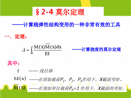
在研究莫尔定理之前,首先应明确:在这一章中,我们将学 习两种能量方法:1,莫尔定理。2,卡氏定理。其中莫尔定理是 今天这节课的内容。并且,在变形能概念的基础上来研究莫尔定 理。
二.定理证明:
1.在原始载荷P1、P2、P3……单独作用下,梁内变形能U
U M 2 xdx L 2EIZ
—— <a>
P1 P2 P3
C EI 2
P0
C
EI 2
f
l
图七
x
l 图八
2.在P0=1单独作用下,梁内变形能U0
U0
M02 xdx
L 2EIZ
—— <b>
P1 P2 P3
P0
C
EI 2
f
l
图七
3. 采用先加P0 =1,然后再加P1、P2、P3…..的加载方 式时,梁内的变形能 U1
x
的形式。
例题总结:
1.从莫尔定理的证明过程及例题的分析过程中,可以看出莫 尔定理实质上就是单位载荷法。若要求某一点的线位移,只需在
该点上沿着线位移的方向作用一单位集中力就行了。若要求解一
截面的转角,也只需在该截面上作用一单位力偶就行了。
2. fc
5ql 4 384EIZ
B
ql3 24EIZ
U1
L
M 0
x M
2EIZ
x2
dx
M
2 0
x
dx
M 2 xdx
M xM0xdx
L 2EIZ
L 2EIZ
L EIZ
4.根据变形能与加载方式无关的道理得:
U1 U1
Zeiss-DiNi使用详细介绍
测量旳成果
Tp –我们所处旳转点数 Cp – 目前点号(控制点或者后视)
电话:
观察和中断测段测量
当您前视观察结束后,您就能够换站了 您能够把水准仪关闭后在换站,当您打 开仪器后您能够直接就进入您刚刚所 在水准环测量中显示按键显示旳例子 在旳地方,而且能够继续您旳水准路线 测量.
当您已经观察结束而且已经观察 了最终旳闭合点,您就能够按下测 段结束键.当您已经观察了一整条 测段了.
5) 输入后视点高程,假如您想另外 计算能够输入 0
6) 输入点号 BM 7) 假如您喜欢能够输入代码.
电话:
观察一条测段
您目前能够开始测量 了
开始测 BM高程
按下测量键 MEASURE (要记住您观察旳是那一边)
Rb – 后视尺子旳读数 HD – 测量旳距离
下一种要观察那个方向? Back=后视 Fore=前视
位. 4) Shut Off: 自动关机时间. 5) Sound: 蜂鸣开关. 6) Language: 语言设置. 7) Date: 日期格式 8) Time: 时间格式
电话:
菜单项 – 测段平差
路线平差能够对闭合路线和附 和路线进行平差.
在您对一种内存中旳闭合环进行平差后,被平差过旳信息会 被保存起来,所以记住在平差之前要下栽下来他旳原始数据. 提醒:平差后旳数据会被永久旳统计下来
REM (#5 key):
允许使用者输入正在测量点 旳代码(用于记忆和保存).
您能够输入更长旳点代码
注意:一旦代码被输入,他会一直保持到您修改后 !!!!
电话:
字母和数字输入
A key
数字和字母输入转换
C key
F key
G key
DSEI120-12A中文资料

0 0.0 0.5 1.0 1.5 V 2.0
VF
Fig. 1 Forward current I versus V
F
F
1.4
1.2 Kf
1.0
0.6
IRM Qr
16
µC 14
TVJ= 100°C VR = 600V
Qr 12 10 8
IF=140A IF= 70A IF= 35A
6
4
2
0
100
°C
357
W
0.8...1.2
Nm
6
g
Symbol
Test Conditions
Characteristic Values
typ.
max.
IR
VF
VT0 rT RthJC RthCK RthJA trr IRM
TVJ = 25°C TVJ = 25°C TVJ = 125°C
VR = VRRM VR = 0.8 • VRRM VR = 0.8 • VRRM
元器件交易网
Fast Recovery Epitaxial Diode (FRED)
DSEI 120
IFAVM = 109 A VRRM = 1200 V trr = 40 ns
VRSM V 1200
VRRM V
1200
Type DSEI 120-12A
TO-247 AD
A
C
C
A
C
A = Anode, C = Cathode
Symbol IFRMS IFAVM ÿÿx IFAV y IFRM IFSM
I2t
TVJ TVJM Tstg Ptot Md Weight
DINI12数字水准仪在七格污水处理厂沉降观测中的应用

可靠 ,已知资料 保存完 整 ,可 以继续使用 。选 取 的沉 降观
测点能代表沉降特征地点 。
3 沉 降观测方法
沉降观 测应 符 合 JJr8删 G/ _ _ 《 筑变 形 测量 规 范》 建
差 【的检验方法 。 2
测点 22 ( 7 个 观测点的布置随建筑物竣工时完成) 。根据项
目 勘察 、取证 ,得知厂区 内基准点 、工 作基点选埋合 理 、 组
收 稿 日期 :2 1-41 0 1 -5 0
作者简介 : 凌
佳 (94 ,男 ,工程 师 ,大学本 科 ,主要 18 一)
前后视 距也 将 自动记 录。因此 ,在 观测过 程 中只需控 制每
()数据无缝传输。以D S 4 O 格式的 P 数据卡为数据存 c
储介 质 ,并可 以方便地将数据传输至各种软件 中。 该数字水准仪 操作 简便 ,精度 高 ,可提 高沉 降观测 的 精度和效率 ,为实现沉降观测内外业一体化提供有利条件。
天气 ;
图片进行 比较和计算 ,得到读数 并且保存 到内存 中u。 J
其主要特点有 :
()精度高 、读数 客观 。配 合 铟钢 尺 ,测 量 中误差 为 1
±0 3m /m。与传统的光学水准仪相 比,DN 1 . mk II 2不存在 误 读 、误记 问题 ,减小了观测误差 。
凌 佳 ,段 文义 ,陶 字
( 浙江省河海测绘院,浙江 杭州 300 ) 108
摘 要 :对 DN1 数字水准仪的功能特点作了介绍。阐述 了对 七格 污水 处理厂建筑物 沉降观测 的方 法 , II 2 列
服务提升案例

双武器系统遥控武器站
双武器系统遥控武器站双武器系统遥控武器站,也有人将其归入中型遥控武器站的范畴,是介于超轻型与中型之间的遥控武器站。
主要武器是12.7毫米机枪或40毫米榴弹发射器,通常安装在武器站的中央、光电装置的上方。
在武器站上还增配1挺5.56毫米或7.62毫米机枪,成为配置两种武器以上的武器站。
挪威康斯博格公司为了填补轻型和中型系统之间的空白,康斯博格公司已在M153遥控武器站的基础上开发出了“保护者”双武器配置遥控武器站,在武器站的右侧增配1挺5.56毫米或7.62毫米机枪。
主要武器是12.7毫米机枪或40毫米榴弹发射器,正面下部设有4具烟幕弹发射器。
“保护者”双武器配置遥控武器站被选入加拿大战术装甲车辆计划,其上除配置12.7毫米机枪或40毫米榴弹发射器外,还可额外配置小口径机枪。
以色列艾尔比特公司以色列在遥控武器站领域发展活跃,埃尔比特系统公司(Elbit Systems)在2010年欧洲萨托利防务展上推出一种新型双武器配置遥控武器站(DRWS),它是该公司RCWS-M 的衍生产品,已进入生产阶段。
澳大利亚陆军已经准备购买该系统。
该型武器站是一种轻型低轮廓双向稳定式系统,不需改进车体就可外装在各种装甲战车、输送车和其它类似平台上。
该型武器站的主要武器是40毫米自动榴弹发射器或12.7毫米重机枪,辅助武器是1挺7.62毫米通用机枪,最大重量200千克。
传感器包括白光电视摄像机、夜用摄像机和激光测距仪。
当两种摄像机被设置为窄视场时,还可以启用自动目标跟踪仪,因此能够探测到5000米以外的各种目标,武器的高低射界为-10°~+60°。
整个系统既可由炮手操作,也可由车长操作。
此外,埃尔比特系统公司还研制出了别具特色的顶置式遥控武器站(ORCWS)。
它既可以是一种双向稳定单武器炮塔,配装各种类型的机枪或自动榴弹发射器,也可以是多武器炮塔,在采用更大口径的UT30系列机关炮的同时,再安装1挺并列机枪和若干具导弹发射器,以及多种传感器。
单兵手持无线电台的创新发展

单兵手持无线电台的创新发展通过战争得来的经验教训是军事理论中要长期遵守的准则。
阿富汗持续的战火以及不久前的伊拉克战争在手持战术无线电台设计方面为通信技术工程师提供了很多经验教训。
在今年9月份举行的伦敦防卫与安全设备国际展(Defence Security and Equipment International,DSEi)上,哈里斯公司(Harris)的军事通信设备国际销售主管查尔斯•施皮拉(Charles Spyra)指出,手持战术无线电台将具备更多功能。
这体现在以往特种部队使用的电台所具备的功能被越来越多地移植到普通单兵无线电台上。
施皮拉先生注意到:“无线电台使用的频率范围正在扩展,数据的传输速度也在提高,以便满足人们在同一信道为多用户提供服务的需要。
宽带通信电台和更多波段的多波段电台是两大发展趋势。
”本文将从硬件和波形两个方面对手持无线电台近年来的创新发展做一简要介绍。
Datron公司在防卫与安全设备国际展上,Datron国际通信公司(Datron World Communications)发布了新型“幽灵”(Spectre)HH-2100V型甚高频手持无线电台。
这种电台在30Mhz-88Mhz 的甚高频频段工作,拥有100个可编程信道,最大输出功率为5瓦。
该电台具备基于全球定位系统的位置报告功能,并使用数字加密波形和全跳频或部分跳频技术来增强通信的安全性。
这种电台还能与Datron国际通信公司出品的PRC2100V 型无线电台联机,后者能够作为背负式电台或车载电台使用,也可作为中继站。
EID公司葡萄牙EID公司是一家战术无线电台制造商,在亚太地区有着很大影响力。
今年,该公司推出了TWH-101型班用无线电台。
这种电台的工作频率为2.4GHz,使用了WiFi技术和该公司的TDMA专有波形,数据传输速率为120Kbps,通信距离不到1公里(0.6英里)。
TWH-101电台系统由TWH-101R收发机、TWH-101G网关和车载充电器组成。
DSEI2x101中文资料
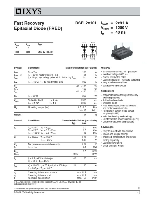
Symbol Conditions Maximum Ratings (per diode)I FRMST VJ = T VJM130A I FAVM ①T C = 50°C; rectangular; d = 0.591A I FRM t P < 10 µs; rep. rating; pulse width limited by T VJM tbd A I FSM T VJ = 45°C;t = 10 ms (50 Hz), sine900A T VJ -40...+150°C T VJM 150°C T stg -40...+150°C P tot T C = 25°C 250W V ISOL 50/60 Hz, RMS t = 1 min 2500V~I ISOL ≤ 1 mAt = 1 s3000V~M dMounting torque (M4)1.5 -2.0Nm 14 - 18lb.in.Weight 24gSymbol ConditionsCharacteristic Values (per diode)typ.max.I RT VJ = 25°C V R = V RRM3.0mA T VJ = 25°C V R = 0.8 • V RRM 1.5mA T VJ = 125°C V R = 0.8 • V RRM 15mA V F I F = 100 A;T VJ = 150°C 1.61V T VJ = 25°C1.87V V T0For power-loss calculations only 1.01V r T T VJ = T VJM6.1m ΩR thJC 0.5K/W R thCK 0.05K/W t rr I F = 1 A; -di/dt = 400 A/µs4060ns V R = 30 V; T VJ = 25°CI RM V R = 100 V;I F = 75 A; -di F /dt = 200 A/µs 2430A L ≤ 0.05 µH; T VJ = 100°C d S Creeping distance on surface min. 11.2mm d A Creeping distance in air min. 11.2mm aAllowable accelerationmax. 50m/s²DSEI 2x101I FAVM =2x91 A V RRM =1200 V trr =40 ns① I FAVM rating includes reverse blocking losses at T VJM , V R = 0.8 V RRM , duty cycle d = 0.5Data according to IEC 60747Features •2 independent FRED in 1 package •Isolation voltage 3000 V~•Planar passivated chips•Leads suitable for PC board soldering •Very short recovery time •Soft recovery behaviourApplications•Antiparallel diode for high frequency switching devices •Anti saturation diode •Snubber diode•Free wheeling diode in converters and motor control circuits•Rectifiers in switch mode power supplies (SMPS)•Inductive heating and melting•Uninterruptible power supplies (UPS)•Ultrasonic cleaners and welders Advantages•Easy to mount with two screws •Space and weight savings•Improved temperature and power cycling capability •Low noise switching •Small and light weightFast RecoveryEpitaxial Diode (FRED)139V RSM V RRMTypeVV 12001200DSEI 2x 101-12PIXYS reserves the right to change limits, test conditions and dimensionsAC-1IK-10LN-9VX-180255075100125150I F A Fig. 3Peak reverse current I RMversus -di F /dtFig. 2Reverse recovery charge Q rversus -di F /dtFig. 1Forward current I F versus V FFig. 6Peak forward voltage V FR and t frversus di F /dt Fig. 7Transient thermal impedance junction to case at various duty cyclesDimensions in mm (1mm = 0.0394“)。
ABB变频器选型

COMMUNICATION ADAPTER PULSE ENCODER INTERFACE DDCS COMMUNICATION OPTION TERMINAL BLOCK TERMINAL BLOCK FUSE SWITCH FUSE LINK CHARGING FUSE POWER RESISTOR POWER RESISTOR POWER RESISTOR POWER RESISTOR SWITCH FUSE CONTR. INVERTER UNIT INVERTER UNIT MAIN CIRCUIT CONNECTOR MAIN CIRCUIT CONNECTOR COMMON MODE FITER COMMON MODE FITER CONNECTOR CONNECTOR POWER SUPPLY PROTECTION SWITCH CONTROL PANEL PANEL INTERFACE BOARD PANEL PLUG CONNECTOR GROUNDING WIRE CDP PANEL EMC SHIELD CONTROL PANEL CABLE ABB 2-3L,DRIVE CONTROL UNIT.MD ABB.2-3L,PPCS BRANCHING&DATAL OGG.UNIT,MD SYSTEM SOFTWARE PROTECTION SWITCH AUXILIARY CONTACT
-P2 -A10 -F7 (-F7) -Q10 (-Q10) (-Q10) (-Q10) (-Q10) (-Q10) -F12 (-F12) -A11 -G11 -G12 -F111 -F112 (-F111) -Q20 (-Q20) -F31 (-F31) -S11 -K11 (-K11) -K13 -K14
常用场效应管参数及代换

常用场效应管参数及替代FGA25N120AND (IGBT)1200V/25A//TO3P (电磁炉用)FQA27N25 (MOSFET)250V/27A/TO3P IRFP254FQA40N25 (MOSFET)250V/40A/280W/0.051Ω/TO3P IRFP264FQA55N25 (MOSFET)250V/55A/310W/0.03Ω/TO3PFQA18N50V2 (MOSFET)500V/20A/277W/0.225Ω IRFP460AFQA24N50 (MOSFET)500V/24A/290W/0.2Ω/TO3PFQA28N50 (MOSFET)500V/28.4A/310W/0.126Ω/TO3P MTY30N50EFQL40N50 (MOSFET)500V/40A/560W/0.085Ω/TO264 IRFPS37N50FQA24N60 (MOSFET)600V/24A/TO3PFQA10N80 (MOSFET)800V/9.8A/240W/0.81Ω/TO3PFQA13N80 (MOSFET)800V/13A/300W/0. Ω/TO3PFQA5N90 (MOSFET)900V/5.8A/185W/2.3Ω/TO3PFQA9N90C (MOSFET)900V/8.6A/240W/1.3Ω/TO3PFQA11N90C (MOSFET)900V/11.4A/300W/0.75Ω/TO3PFFA30U20DN (快恢复二极管)200V/2×30A/40ns/TO3P DSEK60-02A FFPF30U60S (快恢复二极管)600V/30A/90ns/TO220F MUR1560FFA30U60DN (快恢复二极管)600V/2×30A/90ns/TO3P DSEK60-06A MBRP3010NTU (肖特基)100V/30A/TO-220MBRA3045NTU (肖特基)45V/30A/TO-3PISL9R3060G2 (快恢复二极管)600V/30A/35ns/200W/TO247 APT30D60B RHRG3060 (快恢复二极管)600V/30A/35nS/TO247FQP44N10 (MOSFET)100V/44A/146W/0.0396Ω/TO220 IRF3710/IRF540N FQP70N10 (MOSFET)100V/57A/160W/0.025Ω/TO220IRFP450B (MOSFET)500V/14A/0.4Ω/205W/TO3PIRFP460C (MOSFET)500V/20A/0.2~0.24Ω/235W IRFP460KA3162/FAN8800 (Drive IC)单IGBT/MOSFETFET驱动ICRHRP860 (快恢复二极管)600V/8A/30NS/TO-220 MUR860RHRP1560 (快恢复二极管)600V/15A/TO0220 MUR1560RHRP8120 (快恢复二极管)1200V/8A/75W/TO220RHRP15120 (快恢复二极管)1200V/15A/TO220RHRP30120 (快恢复二极管)1200V/30A/125W/TO220单DSEI20-10A RHRG30120 (快恢复二极管)1200V/30A/T03PSSH45N20B (MOSFET)200V/45A/TO3P IRFP260FGL40N150D (IGBT)1500V/40A/TO264快速IGBTFGL60N100BNTD (IGBT)1000V/60A/TO264快速IGBT 1MBH60-100HGTG10N120BND (IGBT)1200V/35A/298W/100ns/TO247HGTG11N120CND (IGBT)1200V/43A/298W/TO247HGTG18N120BND (IGBT)1200V/54A/390W/90ns/TO247FQP5N50C (MOSFET)500V/5A/73W/1.4Ω/TO-220 替代:IRF830,用于35WFQPF5N50C (MOSFET)500V/5A/38W/1.4Ω/TO-220F 替代:IRF830,用于35W FQP9N50C (MOSFET)500V/9A/135W/0.6Ω/TO220 替代:IRF840,用于75W FQPF9N50C (MOSFET)500V/9A/44W/0.6Ω/TO-220F 替代:IRF840,用于75W FQP13N50 (MOSFET)500V/13.4A/190W/0.43Ω/TO220 用于75W/125W产品FQPF13N50 (MOSFET)500V/13.4A/48W/0.43Ω/TO220F 用于75W/125W产品FQD5N50C (MOSFET)500V/5A/1.4Ω/TO252 用于35W FQA16N50 (MOSFET)500V/16A/200W/0.32C/TO3P 用于150W到250W的产品FDP15N50 (MOSFET)500V/15A/0.43Ω/56W/TO220 用于150W左右的产品FQP18N50V2 (MOSFET)500V/18A/0.43Ω/208W/TO220 用于250WG到400W的产品FQPF18N50V2 (MOSFET)500V/18A/0.43Ω/56W/TO220 用于250WG到400W的产品FQA18N50V2 (MOSFET)500V/20A/277W/0.225Ω/TO3P 用于250WG到400W的产品FQA24N50 (MOSFET)500V/24A/290W/0.2Ω/TO3P 用于400W的产品FQA24N60 (MOSFET)600V/23.5A/310W/0.24Ω/TO3P 用于400W的产品FQA28N50 (MOSFET)500V/28.4A/310W/0.126Ω/TO3P 用于400W的产品FQL40N50 (MOSFET)500V/40A/560W/0.085Ω/TO264 用于560W的产品IRF740B (MOSFET)400V/10A/0.55Ω/134W/TO220IRF730B (MOSFET)400V/5.5A/1.0Ω/73W/TO220IRF830B (MOSFET)500V/4.5A/1.5Ω/73W/TO220IRF840B (MOSFET)500V/8A/0.85Ω/134W/TO220IRFP450B (MOSFET)500V/14A/0.4Ω/205W/TO3PIRFP460C (MOSFET)500V/20A/0.2~0.24Ω/235WFQPF5N60C (MOSFET)600V/5A/TO220FFQPF8N60C (MOSFET)600V/8A/TO220FFQPF10N60C (MOSFET)600V/10A/TO220FQPF12N60 (MOSFET)600V/12A/51W/0.65Ω/TO220FFCP11N60 (MOSFET)650V/11A/125W0.32Ω/TO220RHRD660S (快恢复二极管)600V/6A/TO-252RHRP860 (快恢复二极管)600V/8A/75W/TO-220RHRP1560 (快恢复二极管)600V/15A/TO-220单2N7002 (三极管)60V/0.12A/SOT-23 HUF76629D3S (MOSFET)100V/20A/110W/TO-252HUF75639S3S (MOSFET)100V/56A/200W/TO-263ISL9V3040D3S (IGBT)430V/21A/150W/300MJ/TO252ISL9V3040S3S (IGBT)430V/21A/150W/300MJ/TO263ISL9V5036S3S (IGBT)360V/46A/250W/TO262FQP33N10L (MOSFET)100V/33A/52MΩ127W/TO220。
DSEM812 CODESYS Manual

057-317 ISSUE:1DEEP SEA ELECTRONICSDSEM812 CODESYS ManualDocument Number: 057-318Author: Anthony MantonDeep Sea Electronics LtdHighfield HouseHunmanbyNorth YorkshireYO14 0PHENGLANDSales Tel: +44 (0) 1723 890099E-mail:****************************Website: DSEM812 CODESYS Manual© Deep Sea Electronics Ltd.All rights reserved. No part of this publication may be reproduced in any material form (including photocopying or storing in any medium by electronic means or other) without the written permission of the copyright holder except in accordance with the provisions of the Copyright, Designs and Patents Act 1988.Applications for the copyright holder’s writ ten permission to reproduce any part of this publication must be addressed to Deep Sea Electronics Ltd at the address above.The DSE logo and the name DSEControl® are UK registered trademarks of Deep Sea Electronics Ltd.Any reference to trademarked product names used within this publication is owned by their respective companies.Deep Sea Electronics Ltd reserves the right to change the contents of this document without prior notice.Revision History057-317 ISSUE: 1 Page 2 of 36TABLE OF CONTENTSSection Page 1Introduction (4)1.1CLARIFICATION OF NOTATION (5)1.2GLOSSARY OF TERMS (5)1.3RELATED INFORMATION (6)1.3.1TECHNICAL INFORMATION (6)1.4SAFETY INSTRUCTIONS (7)1.4.1GENERAL (7)1.4.2INSTALLATION NOTES (7)2CONNECTING TO CODESYS (8)2.1START NEW PROJECT (8)2.2ETHERNET TCP (9)2.3ETHERNET UDP (10)2.4CONFIGURE SETTINGS AND MONITOR THE DEVICE (12)2.4.1DEVICE SETTINGS PARAMETERS (13)2.4.1.1NEW NETWORK CONFIGURATION (13)2.4.2MANUAL SHUTDOWN (14)2.4.2.1OTHER SETTINGS (15)2.4.3DEVICE SETTINGS I/O MAPPING (16)2.5ADD INPUTS, OUTPUTS AND BUTTONS TO THE PROJECT (17)2.5.1BUTTONS (18)2.5.1.1BUTTON LOCATION (18)2.5.1.2BUTTON POSITION ON THE VISUALISATION (18)2.5.1.3BUTTON SETTINGS (19)2.5.2INPUTS AND OUTPUTS (20)2.5.3DIGITAL INPUT PARAMETER CONFIGURATION (21)2.6USING THE DISPLAY VISUALISATION IN THE PROJECT (22)2.6.1USING CUSTOM IMAGES ON THE DISPLAY (23)2.6.1.1ADDING AN IMAGE POOL (23)2.6.1.2ADDING IMAGES TO THE IMAGE POOL (23)2.6.1.3USING THE IMAGE POOL ON THE DISPLAY (24)2.6.2UTILISING THE TOUCHSCREEN (25)2.6.2.1SWITCHES, SLIDERS, COMBO BOXES, RADIO BUTTONS (25)2.6.2.2NUMBER AND TEXT ENTRY (26)2.7USING THE MOVIE PLAYER (28)2.7.1ADDING THE MOVIE FILE (28)2.8FILE PATH (28)2.9USING THE OVERLAY (29)2.9.1OVERLAY SETTINGS (29)2.10ALTERNATIVE METHODS TO LOAD THE APPLICATION (30)2.10.2UPDATE USING DSESERVICETOOL AND ETHERNET CONNECTION (31)3M812 CODESYS ERROR CODES (32)3.1DEVICE (32)3.2ANALOGUE INPUTS (32)3.3DIGITAL INPUTS (33)3.4DIGITAL OUTPUTS (33)4MAINTENANCE AND WARRANTY (34)5DISPOSAL (34)5.1WEEE (WASTE ELECTRICAL AND ELECTRONIC EQUIPMENT) (34)6MISC (34)Page 3 of 36 057-317 ISSUE: 11 IntroductionThis document details the operation and setup requirements of the DSEM812 CODESYS Controller and Display, part of the DSEControl® range of products.The manual forms part of the product and should be kept for the entire life of the product. If the product is passed or supplied to another party, ensure that this document is passed to them for reference purposes.This is not a controlled document. DSE do not automatically inform on updates. Any future updates of this document are included on the DSE website at Observe the operating instructions. Non-observance of the instructions, operation not in accordance with use as prescribed below, wrong installation or incorrect handling seriously affects the safety of the product, operators and machinery.A robust metal case designed for chassis mounting houses the module. Connections are via locking plug and sockets.The controller is supplied with no application program. The equipment manufacturer is responsible for creating and managing the application program and installing it in the controller. This is achieved using CODESYS V3.5 programming. Contact DSE Technical Support for further details.057-317 ISSUE: 1 Page 4 of 361.1 CLARIFICATION OF NOTATIONClarification of notation used within this publication.1.2 GLOSSARY OF TERMSPage 5 of 36 057-317 ISSUE: 1This document refers to and is referred by the following DSE publications which are obtained from the DSE website: or by contacting DSE technical support: support@ .1.3.1 TECHNICAL INFORMATION057-317 ISSUE: 1 Page 6 of 361.4.1 GENERAL•These instructions are for authorised persons according to the EMC and low-voltage directives.The device must be installed, connected and put into operation by a qualified electrician.•It is not permissible to open the controller or to modify or repair the controller. Modification or repairs to the wiring could result in dangerous malfunctions. Repairs to the controller must be performed by DSE. Contact your original equipment supplier in the case of malfunction.•When the device is unpowered, ensure that no connection pins are connected to a voltage source. Thus, when the supply is switched off, the supply for the electronics, the power outputs and the external sensor supply must be switched off together.•The controller heatsink at the rear heats up beyond normal ambient temperature during operation. To avoid danger caused by high temperatures, protect against contact.•The customer is responsible for performing risk analysis of the mobile working machine and determining the possible safety related functions. The user is responsible for the safe function of the application programs created. If necessary, they must additionally carry out an approval test by corresponding supervisory and test organisations according to the national regulations.•All connectors must be unplugged from the electronics during electrical welding and painting operations.1.4.2 INSTALLATION NOTES•Follow the instructions of the connector manufacturer, specifically with respect to preventing water from entering the device. See Section entitled Cables, Connectors, Harnesses and Spare Parts for details of DSE Part Numbers.•To maintain IP67 rating where connectors have unused pins, ensure the use of a suitable Blanking Insert. In the case of a completely unused connector, the plug must be inserted, fully populated with Pin Blanking Inserts. See Section entitled Cables, Connectors, Harnesses and Spare Parts for details.•M12 protection plugs (supplied) must be installed in both the USB and Ethernet interfaces to ensure IP67 rating when the connectors are not in use. Tighten to 0.8 Nm (0.6 lbf ft). Where IP protection is required when the interfaces are in use, suitable O-rings must be fitted.•The heatsink must be wired to vehicle ground to comply with EMC guidelines. A screw connection point is provided for this purpose. A metallic screw must be used to create anelectrical connection to vehicle / machine ground.Page 7 of 36 057-317 ISSUE: 1057-317 ISSUE: 1 Page 8 of 362 CONNECTING TO CODESYSDSEM812 communicates with, and is programmed by, the CODESYS V3.5 Integrated Development Environment (IDE).2.1 START NEW PROJECTTo begin, start a new project as shown.Page 9 of 36 057-317 ISSUE: 12.2 ETHERNET TCPWith the DSEM812 connected to the same Ethernet network as the PC, Select Device |057-317 ISSUE: 1 Page 10 of 362.3 ETHERNET UDPWith the DSEM812 connected to the same Ethernet network as the PC, Select Device | Communication Settings in the CODESYS V3.5 IDE.All devices found during the scan appear in the Select Device window. The displayed name is factory set to M812 and is changed in the Device Settings screen.Click a device to show its details in the right pane.Wink is not supported by DSEM812Click OK toconnect totheselecteddevice.Page 11 of 36 057-317 ISSUE: 1057-317 ISSUE: 1 Page 12 of 362.4 CONFIGURE SETTINGS AND MONITOR THE DEVICESee the following subsections for details of the Device Settings pages.Successful connection is shown by the green icon. details in the right pane.Page 13 of 36057-317 ISSUE: 12.4.1 DEVICE SETTINGS PARAMETERS2.4.1.1 NEW NETWORK CONFIGURATION2.4.2 MANUAL SHUTDOWN057-317 ISSUE: 1 Page 14 of 362.4.2.1 OTHER SETTINGSAllows monitoring of Memory, Storage and CPU usage.Allows user alarms to be set for Memory, Storage and CPUPage 15 of 36 057-317 ISSUE: 12.4.3 DEVICE SETTINGS I/O MAPPINGThis page is used to monitor the device, and if required, to map the monitored values to program variables.057-317 ISSUE: 1 Page 16 of 36Page 17 of 36 057-317 ISSUE: 12.5 ADD INPUTS, OUTPUTS AND BUTTONS TO THE PROJECT057-317 ISSUE: 1 Page 18 of 362.5.1 BUTTONS2.5.1.1 BUTTON LOCATION2.5.1.2 BUTTON POSITION ON THE VISUALISATIONTo aid positioning of icons on the visualisation, the vertical position of the centre of each button is as follows.Page 19 of 36 057-317 ISSUE: 12.5.1.3 BUTTON SETTINGS057-317 ISSUE: 1Page 20 of 362.5.2 INPUTS AND OUTPUTS2.5.3 DIGITAL INPUT PARAMETER CONFIGURATION2.6 USING THE DISPLAY VISUALISATION IN THE PROJECTCODESYS 3.5 includes the facility to design and manipulate the LCD of the device. While the operation of the CODESYS environment is detailed within the CODESYS online document, this section provides a quick-start guide to using the Visualisation component of CODESYS 3.5.Right-Click Application, select Add Object ….select Add Object ….2.6.1 USING CUSTOM IMAGES ON THE DISPLAYMany applications require custom images to be placed on the DSEM812 display. This is controlled using an Image Pool within CODESYS. The Image Pool acts as a container for the images, which are then selected for display.2.6.1.1 ADDING AN IMAGE POOL2.6.1.2 ADDING IMAGES TO THE IMAGE POOLContinued overleaf…2.6.1.3 USING THE IMAGE POOL ON THE DISPLAYEntries within the Image Pool are automatically detected by the CODESYS Visualisation Toolbox and are available for placing on the Visualisation.Example entries in the Image Pool2.6.2 UTILISING THE TOUCHSCREENThe capacitive touchscreen of DSEM812 mimics the operation of a mouse within the CODESYS environment. The following examples show how to utilise this functionality within the Visualisation.2.6.2.1 SWITCHES, SLIDERS, COMBO BOXES, RADIO BUTTONSMany CODESYS visualisation elements require no additional coding or settings to enable them for use with the Touchscreen. These include Switches, Sliders, Combo Boxes and Radio Buttons. Simply add them to the Visualisation and map a variable to them. Touch them on the screen to operate them.Example:Add a switch to the Visualisation. Usually these are found in the ToolboxLamps/Switches/Bitmaps .During the execution of the application, simply touch the switch on the screen to operate it.2.6.2.2 NUMBER AND TEXT ENTRYNumber entry via the DSEM812 Touchscreen requires the use of a Virtual Numpad.Text entry via the DSEM812 Touchscreen requires the use of a Virtual Keypad.CODESYS includes a simple number pad and a German layout keypad as a Dialog and are utilised as follows.DoubleClick Write a Variable to add this entry to the action listSelect which variable to store the entry intoExample:Upon touching the screen on the Visualisation element, CODESYS displays the selected Dialog. Enter the value required.ESC: Exit without saving the value.OK or : Exit and update the variable with the text or value entered.Should the value be outside the configured range, this is indicated, and the dialog remains on screen to allow the correction to be made.Virtual Keypad Virtual Numpad2.7 USING THE MOVIE PLAYER2.7.1 ADDING THE MOVIE FILE2.8 FILE PATHA file added to the project using Add Object | External File… is placed by CODESYS into the following location in the device file system:‘PlcLogic/Application/MyFileName ’This is the path to the file when using functions from the SysFile library.For the purposes of the movie player, a file added as External File has the additional prefix:‘file:///home/codesys/’Making the complete path for use with the movie player:‘file:///home/codesys/PlcLogic/Application/MyFileName ’2.9 USING THE OVERLAY2.9.1 OVERLAY SETTINGSStructs M870CameraOverlaySettings and VideoOverlaySettings_t, contains options to Enable/Disable the overlay and control the transparency.Structure used for DSEM812 overlay display.2.10 ALTERNATIVE METHODS TO LOAD THE APPLICATIONWhile a live connection to the device by Ethernet is the most common method to load the application, alternatives exist as detailed below. Both options require the creation of a ‘Boot Application’ and the use of DSEServicetool PC Software. First we must connect by Ethernet to a device in order to create the .pkg file.2.10.1 CREATION OF THE BOOT APPLICATIONWithin CODESYS select Online | Create boot applicationBrowse to select the location to store the files. It is convenient to put the files into a new (empty) folder. The example, to the right shows the boot application files in the new folder.All these files (including the sub folder) make up the boot application and must be kept together.Continued overleaf.Connecting to CODESYSPage 31 of 36 057-317 ISSUE: 12.10.2 UPDATE USING DSESERVICETOOL AND ETHERNET CONNECTIONWithin DSEServicetool PC Software scan for and select the device, then select the file Application.app and transfer it to the device. The process of transfer creates Application.pkg and stores it along with the Application.app file.2.10.3 UPDATE USING USBStore the .pkg file on a USB memory stick. Restart the device into Recover Mode | USB Upgrade.3 DSEM812 CODESYS ERROR CODESDSEM812 returns error codes to CODESYS when appropriate. Individual bits are set within the returned value to indicate one or more error conditions. This can be mapped to a variable if required and is available to view within CODESYS under the Device Settings I/O Mapping as shown below.Error Code is a bit field, detailed below.Examples:A Device error value of 120 (01111000 in binary) indicates that all four Output Supplies are Under Voltage.A Device error value of 2 (00000010 in binary) indicates Over Temperature.3.1 DEVICE3.2 ANALOGUE INPUTS057-317 ISSUE: 1 Page 32 of 363.3 DIGITAL INPUTS3.4 DIGITAL OUTPUTSPage 33 of 36 057-317 ISSUE: 1Warranty and Disposal057-317 ISSUE: 1 Page 34 of 364 MAINTENANCE AND WARRANTYThe device is Fit and Forget . As such, there are no user serviceable parts within the controller. In the case of malfunction, you should contact your original equipment manufacturer (OEM).DSE Provides limited warranty to the equipment purchaser at the point of sale. For full details of any applicable warranty, refer to the original equipment supplier (OEM).5 DISPOSAL5.1 WEEE (WASTE ELECTRICAL AND ELECTRONIC EQUIPMENT)If you use electrical and electronic equipment you must store, collect, treat, recycle and dispose of WEEE separately from your other waste6 MISCELLANEOUSThis product includes copyrighted third-party software licensed under the terms of the GNU General Public License. A copy of the corresponding source code for all included third-party software is available on request, please contact DSE Technical Support for additional information.。
- 1、下载文档前请自行甄别文档内容的完整性,平台不提供额外的编辑、内容补充、找答案等附加服务。
- 2、"仅部分预览"的文档,不可在线预览部分如存在完整性等问题,可反馈申请退款(可完整预览的文档不适用该条件!)。
- 3、如文档侵犯您的权益,请联系客服反馈,我们会尽快为您处理(人工客服工作时间:9:00-18:30)。
E 5.85 6.85 0.230 0.420 F 2.54 3.42 0.100 0.135
G 1.15 1.77 0.045 0.070
H
- 6.35 -
Hale Waihona Puke 0.250J0.64 0.89 0.025 0.035
K 4.83 5.33 0.190 0.210
L 3.56 4.82 0.140 0.190 M 0.38 0.56 0.015 0.022
IF = 1 A; -di/dt = 50 A/ms; VR = 30 V; TVJ = 25°C VR = 350 V; IF = 12 A; -diF/dt = 100 A/ms L £ 0.05 mH; TVJ = 100°C
Characteristic Values
typ.
max.
50
mA
25
Advantages
q High reliability circuit operation q Low voltage peaks for reduced
protection circuits q Low noise switching q Low losses q Operating at lower temperature or
t = 8.3 ms (60 Hz), sine
TC = 25°C Mounting torque
Maximum Ratings
25
A
14
A
150
A
100
A
110
A
85
A
95
A
50
A2s
50
A2s
36
A2s
37
A2s
-40...+150
°C
150
°C
-40...+150
°C
62
W
0.4...0.6
Nm
Fig. 6 Peak forward voltage versus diF/dt.
Dim. Millimeter
Inches
Min. Max. Min. Max.
A 12.70 14.73 0.500 0.580 B 14.23 16.51 0.560 0.650
C 9.66 10.66 0.380 0.420 D 3.54 4.08 0.139 0.161
and motor control circuits q Rectifiers in switch mode power
supplies (SMPS) q Inductive heating and melting q Uninterruptible power supplies (UPS) q Ultrasonic cleaners and welders
2
g
Test Conditions
TVJ = 25°C TVJ = 25°C TVJ = 125°C
VR = VRRM VR = 0.8 • VRRM VR = 0.8 • VRRM
IF = 16 A;
TVJ = 150°C TVJ = 25°C
For power-loss calculations only TVJ = TVJM
© 2000 IXYS All rights reserved
1-2
033
DSEI 12, 600 V
Fig. 1 Forward current versus voltage drop.
Fig. 2 Recovery charge versus -di /dt. F
Fig. 3 Peak reverse current versus -diF/dt.
t = 8.3 ms (60 Hz), sine TVJ = 150°C; t = 10 ms (50 Hz), sine
t = 8.3 ms (60 Hz), sine TVJ = 45°C t = 10 ms (50 Hz), sine
t = 8.3 ms (60 Hz), sine TVJ = 150°C; t = 10 ms (50 Hz), sine
space saving by reduced cooling
x IFAVM rating includes reverse blocking losses at TVJM, VR = 0.8 VRRM, duty cycle d = 0.5 Data according to IEC 60747 IXYS reserves the right to change limits, test conditions and dimensions
N 2.04 2.49 0.080 0.115 Q 0.64 1.39 0.025 0.055
© 2000 IXYS All rights reserved
2-2
mA
3
mA
1.5
V
1.7
V
1.12
V
23.2
mW
2
K/W
0.5
K/W
60
K/W
35
50
ns
4
4.4
A
Features
q International standard package JEDEC TO-220 AC
q Planar passivated chips q Very short recovery time q Extremely low switching losses q Low I -values
RM
q Soft recovery behaviour q Epoxy meets UL 94V-0
Applications
q Antiparallel diode for high frequency switching devices
q Anti saturation diode q Snubber diode q Free wheeling diode in converters
Fast Recovery Epitaxial Diode (FRED)
DSEI 12
IFAVM = 14 A VRRM = 600 V trr = 35 ns
VRSM V 640
VRRM V 600
Type DSEI 12-06A
TO-220 AC
A
C
C A C
A = Anode, C = Cathode
Fig. 4 Dynamic parameters versus junction temperature.
Fig. 5 Recovery time versus -diF/dt.
Dimensions
Fig. 7 Transient thermal impedance junction to case.
Symbol IFRMS IFAVM ÿÿx IFRM IFSM
I2t
TVJ TVJM Tstg Ptot Md Weight
Symbol
IR
VF
VT0 rT RthJC RthCK RthJA trr IRM
Test Conditions
TVJ = TVJM TC = 100°C; rectangular, d = 0.5 tP < 10 ms; rep. rating, pulse width limited by TVJM TVJ = 45°C; t = 10 ms (50 Hz), sine
