8S03-E600Y_高清系列主程序_版本说明文件Ver3.0
MOXA UC-8100系列硬件用户手册说明书
UC-8100 Series Hardware User’s ManualEdition 3.1, September 2018/product© 2018 Moxa Inc. All rights reserved.UC-8100 Series Hardware User’s Manual The software described in this manual is furnished under a license agreement and may be used only in accordance withthe terms of that agreement.Copyright Notice© 2018 Moxa Inc. All rights reserved.TrademarksThe MOXA logo is a registered trademark of Moxa Inc.All other trademarks or registered marks in this manual belong to their respective manufacturers.DisclaimerInformation in this document is subject to change without notice and does not represent a commitment on the part of Moxa.Moxa provides this document as is, without warranty of any kind, either expressed or implied, including, but not limited to, its particular purpose. Moxa reserves the right to make improvements and/or changes to this manual, or to the products and/or the programs described in this manual, at any time.Information provided in this manual is intended to be accurate and reliable. However, Moxa assumes no responsibility for its use, or for any infringements on the rights of third parties that may result from its use.This product might include unintentional technical or typographical errors. Changes are periodically made to the information herein to correct such errors, and these changes are incorporated into new editions of the publication.Technical Support Contact Information/supportMoxa AmericasToll-free: 1-888-669-2872 Tel: +1-714-528-6777 Fax: +1-714-528-6778Moxa China (Shanghai office) Toll-free: 800-820-5036Tel: +86-21-5258-9955 Fax: +86-21-5258-5505Moxa EuropeTel: +49-89-3 70 03 99-0 Fax: +49-89-3 70 03 99-99Moxa Asia-PacificTel: +886-2-8919-1230 Fax: +886-2-8919-1231Moxa IndiaTel: +91-80-4172-9088 Fax: +91-80-4132-1045Table of Contents1.Introduction ...................................................................................................................................... 1-1Overview ........................................................................................................................................... 1-2 Model Descriptions .............................................................................................................................. 1-2 Package Checklist ............................................................................................................................... 1-2 Hardware Specifications ...................................................................................................................... 1-2 Hardware Block Diagram ..................................................................................................................... 1-3 2.Hardware Introduction...................................................................................................................... 2-1Appearance ........................................................................................................................................ 2-2 LED Indicators .................................................................................................................................... 2-3 Default Programmable Button Operations .............................................................................................. 2-4 Diagnosing Device and Subsystem Failures ..................................................................................... 2-4 Reset to Default Button ....................................................................................................................... 2-5 Real Time Clock .................................................................................................................................. 2-5 Placement Options .............................................................................................................................. 2-5 DIN Rail Mounting ....................................................................................................................... 2-5Wall or Cabinet Mounting ............................................................................................................. 2-6 3.Hardware Connection Description ..................................................................................................... 3-1Wiring Requirements ........................................................................................................................... 3-2 Connecting the Power .................................................................................................................. 3-2Grounding the Unit ...................................................................................................................... 3-2 Connecting to the Console Port ............................................................................................................. 3-3 Connecting to the Network ................................................................................................................... 3-3 Connecting to a Serial Device ............................................................................................................... 3-4 Inserting the SD and SIM Card ............................................................................................................. 3-4 USB Port ............................................................................................................................................ 3-4 Installing the Cellular/Wi-Fi Module ....................................................................................................... 3-5 A.Regulatory Approval Statements ....................................................................................................... A-11Introduction The UC-8100 series computing platform is designed for embedded data acquisition applications. The computer comes with one or two RS- 232/422/485 serial ports and dual 10/100 Mbps Ethernet LAN ports, as well as a Mini PCIe socket to support cellular modules. These versatile communication capabilities let users efficiently adapt the UC-8100 computers to a variety of complex communications solutions.The following topics are covered in this chapter:❒Overview❒Model Descriptions❒Package Checklist❒Hardware Specifications❒Hardware Block DiagramOverviewThe UC-8100 Series is built around an ARMv7 Cortex-A8 RISC processor that has been optimized for use inenergy monitoring systems, but is widely applicable to a variety of industrial solutions. With flexible interfacing options, this tiny embedded computer is a reliable and secure gateway for data acquisition and processing at field sites as well as a useful communication platform for many other large-scale deployments. Model DescriptionsThe UC-8100 Series includes the following models:•UC-8131-LX: RISC-based platform with 300 MHz CPU, 2 Ethernet ports, 1 serial port, 8 GB eMMC, SD socket, USB port, and Moxa Industrial Linux pre-installed•UC-8132-LX: RISC-based platform with 300 MHz CPU, mPCIe socket for cellular/Wi-Fi module, 2 Ethernet ports, 2 serial ports, 8 GB eMMC, SD socket, USB port, and Moxa Industrial Linux pre-installed •UC-8162-LX: RISC-based platform with 600 MHz CPU, mPCIe socket for cellular/Wi-Fi module, 2 Ethernet ports, 2 serial ports, 8 GB eMMC, SD socket, USB port, and Moxa Industrial Linux pre-installed •UC-8112-LX: RISC-based platform with 1 GHz CPU, mPCIe socket for cellular/Wi-Fi module, 2 Ethernet ports, 2 serial ports, 8 GB eMMC, SD socket, USB port, and Moxa Industrial Linux pre-installed Package ChecklistBefore deploying the UC-8100 computer, verify that the package contains the following items:•UC-8100 embedded computer•Console cable•Power jack•3-pin terminal block for power (Pre-installed on the UC-8100)•5-pin terminal block for UART x 2 (Pre-installed on the UC-8100)NOTE: Notify your sales representative if any of the above items are missing or damaged. Hardware SpecificationsNOTE The latest specifications for Moxa’s products can be found at https://.Hardware Block Diagram2Hardware Introduction The UC-8100 Series of embedded computers are compact and rugged, making them suitable for industrial applications. The LED indicators allow users to monitor performance and identify trouble spots quickly, and the multiple ports can be used to connect a variety of devices. The UC-8100 Series comes with a reliable and stable hardware platform that lets you devote the bulk of your time to application development. In this chapter, we provide basic information about the embedded computer’s hardware and its various components.The following topics are covered in this chapter:❒Appearance❒LED Indicators❒Default Programmable Button OperationsD iagnosing Device and Subsystem Failures❒Reset to Default Button❒Real Time Clock❒Placement OptionsD IN Rail MountingW all or Cabinet MountingAppearanceFront ViewTop & Bottom ViewsTop BottomDimensions [units: mm (in)]LED IndicatorsRefer to the following table for information about each LED. LED NameColorFunctionUSB Green Steady On USB device is connected and working normally Off USB device is not connected.SDGreen Steady On SD Card inserted and working normally OffSD Card is not detectedPowerGreen Power is on and the computer is working normally. Off Power is off.LAN1/2 (On RJ45 connector)GreenSteady On 100 Mbps Ethernet link Blinking Data transmitting Yellow Steady On 10 Mbps Ethernet link BlinkingData transmittingOff Ethernet is not connectedWireless Signal StrengthGreenYellow Red Number of glowing LEDs indicates signal strength 3 (Green + Yellow + Red): Excellent 2 (Yellow + Red) : Good 1 (Red) : PoorOff Wireless module is not detectedDiagnosis Programmable Green Yellow RedRefer to the section Chapter 3 in Hardware Manual for details. These 3 LEDs are programmable; refer to Chapter 5 in Hardware Manual for details.Default Programmable Button OperationsThe push button is used to diagnose device failure or to perform firmware restoration. After depressing the button, release it at the appropriate time to enter the desired mode to either diagnose your device or restore your device to the default configuration. See below for detailed instructions.The LED indicators behave differently when diagnosing a device failure compared to performing a firmware restoration. See the following table for details. StatusRed LED Yellow LED Green LED Executing diagnostics program Blinking Off On Resetting to default configurationBlinkingBlinkingOnDiagnosing Device and Subsystem FailuresThe red LED will start blinking once you press the push button. Keep the button pressed until the green LED is lit for the first time and then release the button to enter diagnostic mode to check which peripherals are available on the UC-8100-LX. When the diagnostic program is executing, the red LED will be blinking. StatusRed LEDYellow LED Green LED Diagnostics program is executing BlinkingOffOnThe following two tables describe the diagnostics results related to hardware defects and system operation.Hardware DefectsIf you observe any of these hardware issues, contact Moxa for further instructions. StatusRed LED Yellow LED Green LED UART1 device issue On On Off UART2 device issue (except UC-8131) OnOnBlinkingLAN 1 device issue On Off Off LAN 2 device issue On Off Blinking Button device issue On Blinking Off TPM device issue On Blinking Blinking LED device issueOnOffOffSystem OperationIf you observe any of the following issues, check the item indicated by the LEDs. StatusRed LED Yellow LED Green LED CPU usage (over 90%) Blinking On Off RAM usage (over 90%) Off On Off Disk usage (over 90%) Off On Blinking File system corruptedBlinkingOnBlinking0 2478Release the button duringthis time to diagnose Time (s)Release the button during this Button pressedReset to Default ButtonPress and hold the Reset Button continuously for at least 5 seconds to load the factory defaultconfiguration . After the factory default configuration has been loaded, the system will reboot automatically. The Ready LED will blink on and off for the first 5 seconds, and then maintain a steady glow once the system has rebooted.We recommend that you only use this function if the software is not working properly and you want to load factory default settings. The Reset to Default functionality is not designed to hard reboot the UC-8100.Real Time ClockThe UC-8100’s real time clock is powered by a non-rechargeable battery. When the computer is not plugged into a power supply, the battery has an estimated life around 1 year. When the computer is plugged into powersupply, the standby current source will be switch to the power supply. We strongly recommend that you do not replace the battery without help from a qualified Moxa support engineer. If you need to change the battery, contact the Moxa RMA service team.Placement OptionsThere are two sliders on the back of the unit for DIN rail and wall mounting.DIN Rail MountingPull out the bottom slider, latch the unit onto the DIN rail, and push the slider back in.Wall or Cabinet MountingPull out both the top and bottom sliders and align the screws accordingly.Another method for wall mounting installation is to use the optional wall mounting kit. Attach two mounting brackets on the side panel of the computer, and fasten with screws. Install the computer on a wall or cabinet by fastening two screws for each bracket.NOTE Before tightening the screws into the wall, make sure the screw head and shank size are suitable by inserting the screw into one of the keyhole-shaped apertures of the wall mounting plates.3 Hardware Connection DescriptionThis section describes how to connect the UC-8100 to a network and various devices for first time testing purposes.The following topics are covered in this chapter:❒Wiring RequirementsC onnecting the PowerG rounding the Unit❒Connecting to the Console Port❒Connecting to the Network❒Connecting to a Serial Device❒Inserting the SD and SIM Card❒USB Port❒Installing the Cellular/Wi-Fi ModuleWiring RequirementsIn this section, we describe how to connect various devices to the embedded computer. You should heed the following common safety precautions before proceeding with the installation of any electronic device: • Use separate paths to route wiring for power and devices. If power wiring and device wiring paths mustcross, make sure the wires are perpendicular at the intersection point.NOTE: Do not run signal or communication wiring and power wiring in the same wire conduit. To avoid interference, wires with different signal characteristics should be routed separately.• You can use the type of signal transmitted through a wire to determine which wires should be kept separate.The rule of thumb is that wiring that shares similar electrical characteristics can be bundled together. • Keep input wiring and output wiring separate.• When necessary, it is strongly advised that you label wiring to all devices in the system.Connecting the PowerTerminal BlockThe UC-8100 has a 3-pin terminal block for a 12 to 24 VDC power input.The figure show how the power input interface connects to external power sources. If the power is properly supplied, the Power LED will light up. The Ready LED will glow a solid green color when the operating system is ready (it may take 30 to 60 seconds for the operating system to boot up).Grounding the UnitGrounding and wire routing help limit the effects of noise due to electromagnetic interference (EMI). Run the ground connection from the ground screw to the grounding surface prior to connecting devices.SG: The Shielded Ground (sometimes called Protected Ground) contact is the bottomcontact of the 3-pin power terminal block connector when viewed from the angle shownhere. Connect the SG wire to an appropriate grounded metal surface.Connecting to the Console PortThe UC-8100’s console port is a 4-pin pin-header RS-232 port located on the top panel of the case. It isdesigned for serial console terminals, which are useful for identifying the boot up message, or for debugging when the system cannot boot up.Serial Console Port & Pinouts Serial Console CablePin Signal1 TxD2 RxD3 NC4 GNDConnecting to the NetworkConnect one end of the Ethernet cable to one of the UC-8100’s 10/100M Ethernet ports (8-pin RJ45) and the other end of the cable to the Ethernet network. If the cable is properly connected, the UC-8100 will indicate a valid connection to the Ethernet in the following ways:The LED indicator in the lower right corner glows a solid green color when the cable is properly connected to a 100 Mbps Ethernet network. The LED will flash on and off when Ethernet packets are being transmitted or received. PinSignal1 ETx+2 ETx-3 ERx+4 –5 –6 ERx-7 –8 – The LED indicator in the upper right corner glows a solid orange colorwhen the cable is properly connected to a 10 Mbps Ethernetnetwork. The LED will flash on and off when Ethernet packets arebeing transmitted or received.Connecting to a Serial DeviceUse properly wired serial cables to connect the UC-8100 to serial devices. The serial ports of the UC-8100 use the 5-pin terminal block. The ports can be configured by software for RS-232, RS-422, or 2-wire RS-485. The precise pin assignments are shown in the following table:Terminal BlockRS-232/422/485 PinoutsPin RS-232 RS-422 RS-4851 TXD TXD+– 2RXDTXD-– 3 RTS RXD+ D+ 4CTS RXD- D- 5GNDGNDGNDInserting the SD and SIM CardThe UC-8100 comes with an SD socket for storage expansion, and a SIM card socket that can be installed with a SIM card for cellular communication. The SD card/SIM card sockets are located on the lower part of the front panel. To install them, remove the screw and the protection cover to access the socket, and then plug the SD card and the SIM card into the sockets directly. Remember to push in on the SD card or SIM card first if you want to remove them.USB PortThe UC-8100 provides 1 USB 2.0 full speed port (OHCI), type A connector, which supports a keyboard or mouse, as well as an external flash disk for storing large amounts of data.Installing the Cellular/Wi-Fi ModuleThe UC-8100 provides an mPCIe socket for installing a cellular/Wi-Fi socket. Follow these steps:1.Remove the screws on the side panel, and take off the cover.2.Find the location of the PCIe socket. Insert the cellular module into the socket, and then tighten the screwsto fasten the socket.3.Next, you need to install the antenna cable. There are two antenna connectors on the cellular module.Connect the cable to either connector.4. Plug the other end of the cable into the connector on the front panel of the UC-8100. Remove the blackplastic cover first.5. Install the connector; place the locking washer first, and then tighten the nut.6. Connect the antenna to the connector.ARegulatory Approval StatementsThis device complies with part 15 of the FCC Rules. Operation is subject to the following two conditions: (1) This device may not cause harmful interference, and (2) this device must accept any interference received, including interference that may cause undesired operation.Class A: FCC Warning! This equipment has been tested and found to comply with the limits for a Class A digital device, pursuant to part 15 of the FCC Rules. These limits are designed to provide reasonable protection against harmful interference when the equipment is operated in a commercial environment. This equipment generates, uses, and can radiate radio frequency energy and, if not installed and used in accordance with the instruction manual, may cause harmful interference to radio communications. Operation of this equipment in a residential area is likely to cause harmful interference in which case the users will be required to correct the interference at their own expense.European Community。
OMAP3530 WinCE 1.00.00.05 DVSDK 发行说明说明书
OMAP3530 WinCE Digital Video Software Development Kit (DVSDK)DVSDK WinCE 1.00.00.05Release Notes Dec 04, 2009Important Note: Users must install the OMAP3530 WINCE DVSDK in order to access certain documentation hyperlinks in this document.IntroductionThis is the first DVSDK WinCE 100 source release targeted for OMAP3530 EVM.The DVSDK WinCE 100 product release is supported on OMAP35x EVM platform. This DVSDK, coupled with WinCE board support package, gives developers the ability to evaluate the hardware and software capabilities of the OMAP35x EVM platform with WinCE 6.0 R2/R3. Developers will be able to evaluate the ARM WinCE programming environment and easily utilize the powerful hardware support of the OMAP3530 SoC for various audio, video, speech and image codecs.This document is divided into the following sections:•Features•Documentation•DVSDK Package Contents•Installation and Usage•Upgrade and Compatibility Information•Host Support•Dependencies•Device Support•Validation Information•Exceptions and Known Issues•Limitations•Special Notes•Technical Support and Product UpdatesFeaturesThis DVSDK release includes support for OMAP3530 and OMAP3525 with the following features and has been tested with WinCE Board Support Package (BSP) R6.12.03:•Support for OMAP35x ES3.1 Silicon version with 256MB LPDDR•Backward compatible with OMAP35x ES2.1 Silicon version with 128MB LPDDR.•XDM 1.0 Codecs from TI.Audio: AAC LC/HE DecoderImage: JPEG Encoder/DecoderSpeech: G.711 Encoder/DecoderVideo: H.264 BP Encoder/Decoder, MPEG4 SP Encoder/Decoder, MPEG2 Decoder•DirectShow Filters•H.264 video decode directshow filter•MPEG4 video decode directshow filter•MPEG2 video decode directshow filter•DVSDK Demos and apps:•DMAI apps for performing file based decode and encodeoperations.•WMP to exercise media playback.•Digital Video Test Bench is not supported with this release.•WinCE 6.0 R2/R3 supportedDocumentation•DVSDK WinCE 100 Getting Started Guide - Hardware and software overview, including how to run demos, install software, and build thedemos. Latest Getting Started Guide can be found online here •Codec Engine Release Notes•Framework Components Release Notes•OMAP3530 Codec Server Release Notes•DaVinci Multimedia Application Interface (DMAI) Release Notes•Direct Show Filters (dshow) Release Notes•DSP/BIOS LINK Release Notes•DSP/BIOS Utilities Release Notes•EDMA3 Low Level Driver Release Notes•WinCE Utils Release Notes•XDAIS Release NotesDVSDK Package ContentsThe DVSDK contains the following components:biosutils_1_02_02 BIOS Utilitieswinceutils_1_00_02 Contiguous memory allocator for WinCEcodec_engine_2_24_01 The Codec Engine provides a framework for creating and interacting with multimedia codecsdmai_1_24_00_07 DaVinci Multimedia Application Interfacedshow_1_00_00_07 TI Directshow multimedia filters. dsplink_1_64 Foundation software for the inter-processorcommunication across the GPP-DSP boundary.framework_components_2_24_01 Framework Components is a collection offramework-independent utility libraries which othersoftware frameworks can build upon.cs1omap3530_1_00_01 Codec Server for decoding and encoding video,audio, speech and image.local_power_manager_1_24_01 Local Power Manager for DSP edma3_lld_01_06_00_01 EDMA3 Low Level Driver containing Resource Manager and Driverxdais_6_24_01_06xDAIS product contains the DSP AlgorithmInterface Standard specification and relateddocumentation and examples. A detailed DVSDK WinCE software manifest can be found hereThe DVSDK depends on the following tools/components:The DVSDK release is shipped with prebuilt components and these tools (exceptXDCTOOLS) are needed only for recompiling the individual components.XDCTOOLS is needed for DVSDK binary installation as well.Important Note: install XDCTOOLS and TI CodeGen tools in directories thatdon’t have any spaces in their path name (default installation path for thesetools may have spaces). Some of the DVSDK component builds fail if thereare spaces in the installation path of these tools.Installation and UsagePlease follow the Getting Started Guide for detailed installation and usageinstructions.Upgrade and Compatibility InformationThe OMAP3530 DVSDK release is independently installable. No upgradeinstructions are available with this release.bSquare WinCE 6.0 BSP Release 6.12.03 or later BSP for WinCE 6.0 R2/R3. bios_5_33_05Stand-alone DSP/BIOS. xdctools_3_10_05_61TI XDC tool. cg6x_6_1_9 TI C6x CodeGen tools.ActivePerl5.8 Active PerlHost SupportThis release supports installation and development on Windows XP workstations.DependenciesThe only known dependencies are listed here.Device SupportThis release supports the Texas Instruments OMAP3530 and OMAP3525 SoC. The verification was done on the OMAP35x Evaluation Module (TMDXEVM3503 and TMDSEVM3530)Validation InformationA sanity test of the DVSDK WinCE 100 build 1_00_00_05 was performed before release to the system test team. The sanity test covered the following tests. The validation was done on OMAP35x EVM.•Play AVI files with MPEG2, MPEG4 and H264 video decoder and MP3 audio decoder using Windows Media Player. Some of the test clips usedfor testing and benchmarking can be found here. http://software-/dsps/dsps_public_sw/sdo_sb/targetcontent/media/wince/index_FDS.html•Run DMAI demonstration applications as described in Getting Started Guide.In addition this release has gone through a complete QA cycle.Exceptions and Known Issues•MP3 playback can only be done on the ARM. This results in higher ARM-side CPU load.•Only AVI containers are supported.•AV synchronization is sometimes off for H.264 video clips at D1 resolution when the bitrate is high (e.g. >= 2Mbps) on Omap3530 ES2.1 siliconreading the media files from SD card. Performance can be improved byusing ES 3.1 silicon with multiple block reads enabled for the SDIO driver.•WMP cannot be run at the same time as DMAI applications, due to lack of an arbitrator of DSPLINK resources.•When performing jpeg image encode using DMAI application of an image with dimension (height or width) that is not a multiple of 16, leads todistorted output. This is a JPEG encoder known limitation.•When performing jpeg image encode using DMAI application, it was observed that using qfactor above 96 leads to misalignment in outputimage.•When performing AAC audio decode using DMAI application, high tone heard in decoded file after an aac decode operation.•When performing AAC audio decode using DMAI application, Mono files are decoded as dualmono during aac decode operations.•DMAI application does not support 411p and 422i as possible chroma formats•The default CMEM configuration allows JPEG encode and decode of images with resolutions upto 1280x720 (1MPixel) with YUV444, YUV422,YUV420 formats. Images of higher resolution can be encoded/decodedwith appropriate increase in CMEM buffer configuration within limits ofavailable memory•Rotation may not work for Video codecs that are part of WinCE 6.0 running on ARM (e.g, MPEG1 video, WMV video). These codecs do not handle the stride information properly. Please contact Microsoft for further details.•SDOCM00057731: MPEG2 Decoder: Flicker is observed at top of the display while decoding Mpeg2 streams of resolution 352x240 with videodecode•SDOCM00062310: MPEG2 Decoder: Generated yuv resolution is not same as the input stream resolution for some MP streams•SDOCM00060533: MPEG2 Decoder: Unable to decode certain clips @ QCIF resolutionFor latest list of known issues, please click on issues list. If this is your first time accessing this database please create an account hereDefects Fixed in DVSDK WinCE 1.00.00.05•Updated direct show filters enable Video Rotation using VRFB for Video codecs running on the DSP (H.264 decode, MPEG2 decode, MPEG4decode).•Optimization in Multimedia framework, higher DSP clock speed as well as adjustment in display driver buffer settings improves multimediaperformance. H.264 video clips at D1 resolution with bitrates of upto2Mbps can be played without any AV sync issue on ES2.1 silicon withmedia files on SD card. MPEG2 and MPEG4 video clips at D1 resolutionwith bitrates upto 4Mbps can be played without AV sync issues.Performance is further improved by using ES 3.1 silicon with multiple block reads enabled for the SDIO driver.Defects Fixed in DVSDK WinCE 1.00.00.04•CERuntime_exit() API is called by TI multimedia filter when closing Windows Media Player. This should free up unused resources.•Benchmarking (--benchmark option) is now supported in DMAI applications •WMP hangs due to exception in timm.dll when unsupported input file is selectedDefects Fixed in DVSDK WinCE 1.00.00.03•Reducing the window size of the Windows Media Player to a size smaller than the frame size may result in corrupted output.•Video display is corrupted when part of the display window lies outside the LCD display.•Directshow filters do not meet real-time and display is corrupted when video renderer operates in GDI mode (ie. when Windows Media Player ishidden by another window). This is because GDI mode requires YUV toRGB conversion of the DSP codec output frames.•DMAI Video Encode - for both H.264 and MPEG4 files, error pertaining to contiguous buffer causes failure•DMAI Image Encode - CMEM configurations to be provided for 1920x1280 and above resolutionsLimitationsSpecial Notes•In order to experience the demos and apps that comes with DVSDK WinCE 100, please refer to the Getting Started Guide.Technical Support and Product UpdatesPlease register your EVM serial number as instructed on the printed Read Me 1st Card in order to download the updated software release as soon as it becomes available.•For questions and support on the DVSDK WinCE 100, please visit .•Please be sure to read the Digital Video Software Development Kit (DVSDK) release notes, printed documentation and Getting Started Guide for general information.• A developer wiki site is available at/index.php?title=Main_Page. For information onOMAP35x, search for OMAP35x in the google toolbar embedded in thepage. User contributions are encouraged.。
denon dcd-600ne 操作说明书
DCD-600NE COMPACT DISC PLAYER 操作说明书附件4安装电池5遥控器的操作范围5特点6高音效6高性能6部件名称与功能7前面板7显示屏9后面板10遥控器11连接方法连接放大器18连接带有数字音频输入端子的设备19连接定时器设备20连接电源线21播放基本操作23开启电源23切换电源至待机23切换显示屏亮度24切换纯直入模式24播放CD25播放CD25以特定顺序播放曲目(编程播放)27播放DATA CD28播放文件29使用定时器播放功能31设置设置自动待机模式32提示提示34故障诊断35电源无法开启/电源自动关闭36使用遥控器无法执行操作37本机显示屏不显示内容37不发出声音38声音中断或出现噪音38无法播放光碟39保修和修理40附录播放光碟41文件41文件的播放顺序43关于文件夹和文件43使用媒体的注意事项44装入光碟44关于媒体的使用45清洁光碟45术语解释46商标信息47规格48索引51感谢您购买本Denon产品。
为了确保正确操作,请在使用本品前认真阅读本操作说明书。
阅读之后,请务必妥善保管以备将来参考。
附件请检查并确认本产品附带下列部件。
安装电池1沿箭头所示方向抬起并取下后盖。
2按照指示将两节电池正确插入电池匣内。
3装上后盖。
注0为防止损坏电池或电池漏液 :0请勿将新旧电池混合使用。
0请勿使用两种不同类型的电池。
0如果打算长时间不使用遥控器,请取出遥控器中的电池。
0如果电池漏液,须仔细地擦去电池匣内的漏液,然后装入新电池。
遥控器的操作范围操作遥控器时应将其指向遥控感应窗。
特点高音效0AL32 Processing和高精度32位/192 kHz数模转换器配有AL32 Processing,Denon自有的模拟波形再现技术。
通过将16位数字数据扩展到32位,增强了弱信号的再现。
另外还配备了一个可兼容的32位/192 kHz的高精度数模转换器,用于将AL32 Processing扩展的数字数据转换为模拟信号。
星锐 SVC9000 系列软交换服务器使用手册
2 硬件及安装说明 ..................................................................................................................................8
2.1 SVC91000 硬件说明......................................................................................................................8 2.1.1 SVC91000 前面板说明 ...........................................................................................................8 2.1.2 SVC91000 后面板说明 ...........................................................................................................9
蒙德SL3D(E4A)系列一体化控制器使用手册
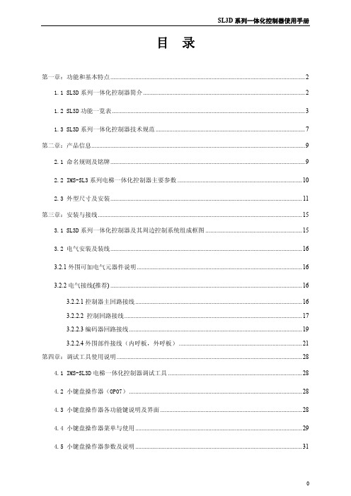
目 录第一章:功能和基本特点 (2)1.1 SL3D系列一体化控制器简介 (2)1.2 SL3D功能一览表 (3)1.3 SL3D系列一体化控制器技术规范 (7)第二章:产品信息 (9)2.1 命名规则及铭牌 (9)2.2 IMS-SL3系列电梯一体化控制器主要参数 (10)2.3 外型尺寸及安装 (11)第三章:安装与接线 (15)3.1 SL3D系列一体化控制器及其周边控制系统组成框图 (15)3.2 电气安装及装线 (16)3.2.1外围可加电气元器件说明 (16)3.2.2电气接线(推荐) (16)3.2.2.1控制器主回路接线 (16)3.2.2.2 控制回路接线 (17)3.2.2.3编码器回路接线 (19)3.2.2.4外围部件接线(内呼板,外呼板) (21)第四章:调试工具使用说明 (28)4.1 IMS-SL3D电梯一体化控制器调试工具 (28)4.2 小键盘操作器(OP07) (28)4.3 小键盘操作器各功能键说明及界面 (28)4.4 小键盘操作器菜单与使用 (29)4.5 小键盘操作器参数及说明 (31)第五章:应用与调试 (41)5.1 电梯运行时序图 (41)5.2 电梯调试流程图 (41)5.3 电梯调试总步骤 (42)5.3.1 慢车调试步骤流程 (42)5.3.2 快车调试过程 (47)5.4 电梯功能调试 (49)5.5 舒适感调试 (50)第六章:故障与对策 (53)6.1 故障的种类 (53)6.2 故障信息 (53)6.2.1外部故障信息与处理 (53)6.2.2 内部故障信息与处理 (54)6.2.3 变频器故障信息 (54)附件:液晶手持操作器使用说明 (59)液晶手持操作器外观及各功能键说明 (59)液晶显示流程图及参数说明 (60)监视菜单及参数设置菜单框图 (60)窗口及操作说明 (61)第一章:功能和基本特点1.1 SL3D系列一体化控制器简介SL3D系列一体化控制器是由蒙德电气有限公司自主研发、生产的具有先进水平的智能型串行通讯电梯控制系统。
Huawei DevEco Studio使用指南_鸿蒙学堂
文档内容来自鸿蒙官方网站,鸿蒙学堂 整理
Huawei DevEco Studio 使用指南
2.3 运行 Hello World.........................................................................................................11 3 工程管理......................................................................................................................................14
3.2 支持的设备模板和编程语言 ........................................................................................ 17 3.3 创建一个新的工程.........................................................................................................18
2.2 配置开发环境 ................................................................................................................... 4 2.2.1 npm 设置............................................................................................................. 4 2.2.2 设置 Gradle 代理................................................................................................ 5 2.2.3 设置 DevEco Studio 代理................................................................................ 6 2.2.4 下载 HarmonyOS SDK .................................................................................... 8
208A数控电源时序V3.0说明书
V3.0时序208A数控电源z 使用前,请务必阅读此栏并正确使用。
z 以下注意事项是有关安全的重要内容,请务必遵守。
z 阅读后请放置在随时可查阅的地方。
标志为能安全正确地使用本产品,避免给您和他人带来人身伤害或财产损失,在此处列出了许多标志。
请在充分理解标志内容的基础上阅读本说明书。
标志记号禁止符号禁止拆解 禁止 禁止触 摸强 制拔出电源 插头请勿用湿手触摸电源插头请勿用湿手插入、拔出电源插头。
否则可能引起触电。
禁止请勿用力拉拽电源软线拔出电源插头时,请勿用力拉拽电源软线。
电源软线受损会引起火灾,触电。
请务必手握插头拔出。
禁止 移动时请拔出电源插头在连接插头的状态下移动,会损伤电源软线,可能引起火灾,触电。
拔出电源插头请勿堵塞通风口堵塞通风口,内部热量积聚,可能引起火灾。
禁止请勿将本机置于潮湿或多尘的地方请勿将本机置于潮湿、多尘的地方,或阳光直射处、热器具附近,以及沾染油烟或热气的地方。
否则可能引起火灾,触电。
禁止注意表示若错误操作可能导致人员受伤或物品损坏。
1安全注意事项通入电源前将音量调至最小若在大音量状态下接通电源,会突然发出很大声音,造成听力障碍。
清洁电源插头及插座部位电源插入的插座部位积累过多灰尘,可能引起火灾。
所以请定期清洁插座部位。
此外,电源插头请插入到根部。
强制 检修或长期不使用时的注意事项检修或长期不使用时,为确保安全请切断电源开关,并将电源插头从插座中拔出。
如不遵守,可能引起触电·火灾。
拔出电源插头发生异常情况发生以下情况,请切断电源开关,拔出电源插头并与销售商联系。
如继续使用,可能引起火灾·触电。
z 冒烟、有异味 z 内部进水或有异物 z 跌落、外壳破损 z 电源软线损伤(电源软线线芯露出、折断) z 无声音拔出电源插头请勿打开、改装内部结构内部有高电压部位,如打开、改装内部结构可能引起火灾·触电。
请到销售店进行内部检查·调整·修理。
优モー德600 优モー德600ND智能燃ume报警控制面板说明书

Unimode 600 /Unimode 600NDIntelligent Fire Alarm Control Panel50110073-001:Rev A • AUnimodeGeneralThe Unimode 600 is an intelligent analog/addressable fire alarm control panel (FACP). The basic Unimode 600 panel contains one built in signaling line circuit (SLC), which can support 159 LiteSpeed sensors and 159 LiteSpeed modules or per loop. Additional SLC loops can be added using the model 5815XL SLC expander to increase the overall point capacity to a maximum of 636 points per panel.Unimode 600 has the interconnection capability for up to 8panels. The system has two modes of operation, multiple pan-els covering one larger building, or multiple independent build-ings.Unimode 600ND is used in a networked system where at least one Unimode 600 is in the system. It is the same as an Uni-mode 600 without the display.Unimode 600 has eight on-board Flexput™ circuits that can be configured for auxiliary power, notification outputs, or for con-ventional smoke detector inputs (Class A or Class B). The FACP also has a built-in, dual-line digital fire communicator,Form C trouble relay, and two programmable Form C relays.Unimode 600 has powerful features such as detector sensitiv-ity, day/night thresholds, drift compensation, pre-trouble maintenance alert, and calibration trouble alert.Unimode 600 supports a variety of devices, including Unimode 600ANN remote annunciator, 5824 serial/parallel printerinterface module (for event logging system reports), intelligent power module, and Fire-Lite (LiteSpeed) devices.Features•Built-in support for up to 159 LiteSpeed sensors and 159LiteSpeed modules. SLC expander will increase overall capacity to 636 points per Unimode 600 panel.•Unimode 600ND is used in a networked system where at least one Unimode 600 is in the system.•Up to eight Unimode 600 or Unimode 600ND panels can be networked providing up to 5088 total points.•Networked panels can be configured to emulate a large vir-tual system or can be segmented into separate sites for multiple building applications.••Built-in UL listed digital communicator for remote reporting of system activity and system programming.•9.0A of output power is available through 8 sets of terminals for notification and auxiliary applications per panel.•Supports Class B (Style 4) and Class A (Style 6 or Style 7)configuration for SLC, and SBUS’s.•Flexput™ I/O circuits configurable for auxiliary power, notifi-cation outputs, or conventional smoke detector inputs. Noti-fication circuits can be configured as Class A (Style Z) or Class B (Style Y). 2- and 4-wire smoke detectors can be configured as Class A (Style D) or Class B (Style B).•Built-in USB interface for programming.•Two RS-485 buses provide communication to system accessories.•Dedicated Form C trouble relay and two general purposeForm C programmable relays rated at 2.5 amps at 24 VDC.Unimode 600•13 preset notification cadence patterns (including ANSI 3.41) and four user programmable patterns.•Four line LCD display with 40 characters per line.•Built-in synchronization for appliances from AMSECO, Gentex®, System Sensor®, and Wheelock®.•999 software zones and 999 output groups.•Programmable date setting for Daylight Saving Time.•JumpStart auto programming allows for faster set up time by selecting default options for many programming tasks.•The Unimode 600 / Unimode 600ND can be surface or flush mounted.•Four programmable function keys.SpecificationsUnimode 600 AC: 120 VAC, 50/60 Hz, 5.0ATotal Accessory Load: 9A @ 24 VDC power-limitedStandby Current: 290 mAAlarm Current: 530 mABattery Charging Capacity: 17 to 55 AHBattery Size: 18 AH max. allowed in control panelcabinet. Larger capacity batteries can be housed inRBB or AB-55 accessory cabinet.Flush Mount Dimensions:14.75”W x 25”H x 4”D (37.5cm W x 63.5cm H x 10.16cm D) Overall Dimensions:16”W x 26.4”H x 4.65”D (40.6cm W x 67cm H x 11.8cm D) Weight: 28 lbs. (12.8 kg)Operating Temperature: 32°F – 120°F (0°C – 49°C) Humidity: 10% – 93% non-condensingEight circuits that can be programmed individually as:-Notification Circuits: 3A per circuit @ 24 VDC,power-limited-Auxiliary Power Circuits: 3A per circuit @ 24 VDC,power-limited-Initiation Circuit: 100 mA per circuit @ 24 VDC,power-limitedRequirements: FCC Part 15 & Part 68 approvedJack: RJ31X (two required)Listings and ApprovalsThese listings and approvals apply to the modules specified in this document. In some cases, certain modules or applications may not be listed by certain approval agencies, or listing may be in process. Consult factory for latest listing status.• NFPA 13, NFPA 15, NFPA 16, NFPA 70, & NFPA 72• UL Listed: S232Approved Releasing Solenoid Manufacturer Part number Rating Current Freq Asco T8210A107 24 VDC 3 A max 0 Hz Asco 8210G207 24 VDC 3 A max 0 Hz Product Line InformationUnimode 600 Intelligent Fire Alarm Control Panel Unimode 600ND Intelligent Fire Alarm Control Panelwithout built in displayUnimode 600ANN Red Remote Annunciator. Four lineLCD annunciator with 40 charactersper line.Unimode 600ANNG Gray Remote Annunciator. Four lineLCD annunciator with 40 charactersper line.5815XL Signal Line Circuit (SLC) Expander 5496 6 amp intelligent Power Module 5824 Serial/Parallel Printer InterfaceModule5880 LED I/O Module5865-3 & 5865-4 LED Fire Annunciators5883 Relay Interface BoardUnimode 600PK Software Suite - 2. Providesprogramming, upload/download, andevent reportingRBB: Remote Battery Box AccessoryCabinet. Use for backup batteries upto 35 AH.Dimensions: 16” W x 10” H x 6” D. AB-55 Remote Battery Box AccessoryCabinet. Use for backup batteriesthat are 35 AH - 55AH.Dimensions: 20” W x 12” H x 7.5” D.Fire-Lite (LiteSpeed) DevicesSee the document listed below for a complete listing of the devices:PN 15384 Fire-Lite Device Compatibility DocumentThis document is not intended to be used for installation purposes.We try to keep our product information up-to-date and accurate.We cannot cover all specific applications or anticipate all requirements.All specifications are subject to change without notice.For more information, contact Tyco. Phone:(561) 988-3600, Fax: (561) 988-3675 Made in the U.S.A.。
CMS8S5880与CMS8S003功能比较说明V1.0(1)

CMS8S5880与CMS8S003比较说明1、CMS8S5880(20PIN)与CMS8S003(24PIN)引脚对比2、CMS8S5880与CMS8S003寄存器对比说明:该章节红色字体为新增项,蓝色字体为改动项。
CAPES 捕获通道1-3模式: (CMS8S5880新增位,CMS8S003为保留位)0= 上升沿捕获到CC0L/CC0H-CC3L/CC3H寄存器;1= 下降沿捕获到CC0L/CC0H-CC3L/CC3H寄存器。
ADCHS<4>: (CMS8S5880新增位,CMS8S003为保留位)ADC模拟通道选择位第<4>位,详见ADCON0.ADCHS说明;1= ADCHS<3:0>选择AN16-AN31通道(不存在的通道可忽略);0= ADCHS<3:0>选择AN0-AN15通道(不存在的通道可忽略)。
TF3/TF4位:CMS8S003中为仅读位(R)CMS8S5880为可读可写位(R/W)。
PWMnCNTECMS8S003仅可由硬件清0,CMS8S5880可由硬件清0,也可软件写0。
Bit3:CMS8S003中为PP3PWM,P3口中断优先级控制位和PWM中断优先级控制位CMS8S5880中为PP3,仅为P3口中断优先级控制位Bit3:CMS8S003中为PWM中断优先级控制位(必须和EIP1.PP3PWM设置相同)CMS8S5880中为PWM中断优先级控制位(无条件)UART1_PORT: (CMS8S5880新增位,CMS8S003为保留位)UART1端口选择选择位;0= 选择TXD1,RXD1功能端口;1= 选择[TXD1],[RXD1]功能端口。
UART1_CKS1: (CMS8S5880新增位,CMS8S003为保留位)UART1的定时器时钟源选择位高位,与UART1_CKS组成两位时钟源选择:{UART1_CKS1,UART1_CKS}00= Timer1的溢出时钟;01= Timer4的溢出时钟;10= Timer2的溢出时钟;11= BRT的溢出时钟;UART0_CKS1: (CMS8S5880新增位,CMS8S003为保留位)UART0的定时器时钟源选择位高位,与UART0_CKS组成两位时钟源选择:{UART1_CKS1,UART1_CKS}00= Timer1的溢出时钟;01= Timer4的溢出时钟;10= Timer2的溢出时钟;11= BRT的溢出时钟;MLOCK<7:0>: 存储器操作使能位。
创维8S01-8S02-8S03机芯维修手册

创维8S01机芯-E800A系列产品维修手册一 产品综述1.1 机芯概述本机芯采用MSTAR公司的高集成芯片MSD6A801,是一颗功能强大的超级单芯片,采用Android4.0操作系统。
采用符合公司标准的PCB制板,可配多种新标准结构机型;硬件系统由主板、电源板(或外加恒流板)、接收板(感光模块包含在其中)、指示灯板和键控板组成;可以支持1366*768和1920*1080的液晶屏。
1.2机芯概述本机芯具有多种信号接口,功能配置如下:A.1路模拟电视信号输入(与有线数字同输入端口),1路视频输入, 1路分量输入,2路HDMI输入,1路VGA输入;B.1路网络接口, 3路USB接口,两路麦克风输入;C.3路音频输入:1路视频的,1路分量的,1路VGA的;D.1路视频输出,1路重低音输出;E. 1 路数字音频输入;本机芯语音小博士、多屏互动等 功能。
本机芯可以通过VGA端口用烧录工具或者从USB1口进行软件升级和烧录。
1.3主要技术规格1.支持ISP(在系统可编程)功能,同时支持USB升级功能;2.内置双核ARM Cortex A9 和双核图形处理器 Mali400;3.内置22G bit的存储器;4.内置无线WIFI,支持802.11N;5.支持PAL、NTSC视频解码,内置3D梳状滤波器;6.支持各种音频处理,支持SRS功能;7.内置中频处理,降低成本;8.3D-DEINTELACE,自动检测3:2,2:2电影模式;9.3D降噪,六基色处理,水平方向MEMC(配合6M20,3D-MEMC);10.LVDS输出可到10BIT,1920×1080;11.多媒体接口USB2.0,支持音画同播,支持网上的大部分格式;12.核心供电为1.28V,整机功耗小于0.5W,封装为LFBGA536;13.支持硬盘的格式FAT32和NIFS;14.功放支持2.1声道;15.支持3D功能;16.各通道最高可支持的格式如表1.1所示:输入通道最高可支持的格式TV PAL/NTSCAV PAL/NTSCYUV/VGA 1080P/60HDMI HDMI1.3 1080P/60/12BITUSBMPEG2 1080P/60MPEG4 1080P/60RM 720P/60H.264 1080P/60表1.1 各通道最高可支持的格式二 电路介绍2.1、 主板与副板、扩展板的接口定义如下:1.主板与副板接口:图2.1 主板与副板接口说明:PIN1、2:IIC总线,预留用来做键控板的一种通讯方式;PIN3:键控板的机械按键接的IO口,上拉3.3V,实现按键功能;PIN4、5:键控的2路模拟电压输入,接CPU的A/D口;PIN7:键控板的供电,可接3.3V或者5V;PIN9:遥控IR的输入;PIN11:LED指示灯颜色切换控制,接CPU的GPIO;PIN13:环境光检测信号输入,为模拟电压,接CPU的A/D口;PIN14:接收板供电,可接主板电源standby 3.3V或者standby 5V;PIN6、8、10、12:接地。
瑞星企业终端安全管理系统软件3.0用户手册
瑞星 ESM 下一代网络版 3.0 快速安装指南
目录
目录 ...................................................................................................................................... 1
ቤተ መጻሕፍቲ ባይዱ北京瑞星网安技术股份有限公司
2
瑞星 ESM 下一代网络版 3.0 快速安装指南
任务等管理数据给全网客户端,同时又会接收客户端的日志、状态等信息,并及时写入数据 中心,独特的负载均衡方案,使得业务中心具备更强的负载能力,突破传统方式的网络连接 瓶颈。 扩展中心:除系统必备中心(管理中心、数据中心、业务中心)之外的其它扩展中心。目前 只包括升级中心、补丁下载中心。 补丁下载中心:主要用于存储补丁文件,管理中心下载任务。 升级中心:用于全网部署、升级的工作。 客户端:企业安装瑞星企业终端安全管理系统软件客户端的计算机。 瑞星企业终端安全管理系统软件采用分布式体系,结构清晰明了,管理维护方便。管理员只 要拥有管理员账号和口令,就能在网络上任何一台有网页浏览器的计算机上,实现对整个网 络上所有计算机的集中管理。
2019
瑞星 ESM 下一代网络版 3.0 快速安装指南
瑞星 ESM 下一代网络版
快速安装指南
快速使用指南用于指导用户快速安装和使用瑞星 ESM 下一代网络版。指南中介 绍了瑞星 ESM 下一代网络版的安装方法。请在安装瑞星 ESM 下一代网络版前认真 阅读本指南。
北京瑞星网安技术股份有限公司
北京瑞星网安技术股份有限公司0 2019.1
2.1. 数据中心 ........................................................................................................................................................... 3 2.2. 管理中心(manager) ........................................................................................................................................... 3 2.3. 业务中心(bus) ................................................................................................................................................... 4 2.4. 升级中心(ruc).................................................................................................................................................... 5 2.5. 补丁下载中心(rua)............................................................................................................................................ 6 2.6. Windows 客户端(ep) .......................................................................................................................................... 7 2.7. Linux 客户端...................................................................................................................................................... 7 2.8. 远程管理控制台................................................................................................................................................ 9
pro-face sp5000系列 硬件手册说明书

目录
SP5000-MM01-CS-PDF_O
安全信息 ....................................................................................................7 关于本书 ....................................................................................................8 概述......................................................................................................... 11
对于将本指南或其内容用作商业用途的行为,施耐德电气未授予任何权利或许可,但 以“原样”为基础进行咨询的非独占个人许可除外。
施耐德电气的产品和设备应由合格人员进行安装、操作、保养和维护。
由于标准、规格和设计会不时更改,因此本指南中包含的信息可能会随时更改,恕不 另行通知。
在适用法律允许的范围内,对于本资料信息内容中的任何错误或遗漏,或因使用此处 包含的信息而导致或产生的后果,施耐德电气及其附属公司不会承担任何责任或义 务。
标准主机模块 ................................................................................28 增强型主机模块............................................................................. 30 开放型主机模块............................................................................. 32 LED 指示 ......................................................................................34 显示模块 ............................................................................................35 精良显示模块 ................................................................................35 高级显示模块 ................................................................................39 LED 指示 ......................................................................................42 规格......................................................................................................... 44 一般规格 ............................................................................................44 电气规格....................................................................................... 44 环境规格....................................................................................... 46 结构规格....................................................................................... 47 功能规格 ............................................................................................49 显示规格....................................................................................... 49 存储器 ..........................................................................................51 时钟 .............................................................................................51 触摸屏 ..........................................................................................51 接口规格 ............................................................................................52 接口规格....................................................................................... 52 接口连接....................................................................................... 54 用于 COM1/COM2 的串行接口 (RS-232C 和 RS-422/RS485) .............................................................................................57 辅助输出/扬声器输出接口 (AUX) ....................................................59 DVI-D 输出接口.............................................................................60 尺寸......................................................................................................... 62 标准主机模块...................................................................................... 62 SP-5B00 ......................................................................................62 增强型主机模块 ..................................................................................63 SP-5B10 ......................................................................................63 开放型主机模块 ..................................................................................63
SD-530ESE DVD播放器说明书

DVD PLAYEROWNER ’S MANUALMODEL : SD-530ESEBefore connecting, operating or adjusting this product,please read this instruction booklet carefully and completely.S S u u rr r rrr o o u u n n d d S S o o u u n n dd 33DDI N T R O D U C T I O NSafety Precautions(Continued)SOME DOS AND DON'TS ON THE SAFE USE OF EQUIPMENTThis equipment has been designed and manufactured to meet international safety standards but, like any electrical equipment, care must be taken if you are to obtain the best results and safety is to be assured. So, please read the points below for your own safety. They are of a general nature, intended to help you with all your electronic consumer products and some points may not apply to the goods you have just purchased.**************DO read the operating instructions before you attempt to use the equipment.DO ensure that all electrical connections (including the mains plug, extension leads and inter-connections between the pieces of equipment) are properly made and in accordance with the manufacturer's instructions. Switch off and withdraw the mains plug before making or changing connections.DO consult your dealer if you are ever in doubt about the installation, operation or safety of your equipment.DO be careful with glass panels or doors on equipment**************DON'T remove any fixed cover as this may expose dangerous voltages.DON'T obstruct the ventilation openings of the equipment with items such as newspapers,tablecloths, curtains, etc. Overheating will cause damage and shorten the life of the equip-ment.DON'T allow electrical equipment to be exposed to dripping or splashing, or objects filled with liquids, such as vases, to be placed on the equipment.DON'T place hot objects or naked flame sources such as lighted candles or nightlights on, or close to equipment. High temperatures can melt plastic and lead to fires.DON'T use makeshift stands and NEVER fix legs with wood screws - to ensure complete safe-ty always fit the manufacturer's approved stand or legs with the fixings provided according to the instructions.DON'T use equipment such as personal stereos or radios so that you are distracted from the requirements of traffic safety. It is illegal to watch television whilst driving.DON'T listen to headphones at high volume, as such use can permanently damage your hear-ing.DON'T leave equipment switched on when it is unattended unless it is specifically stated that it is designed for unattended operation or has a stand-by mode. Switch off using the switch on the equipment and make sure that your family know how to do this. Special arrangements may need to be made for infirm or handicapped people.DON'T continue to operate the equipment if you are in any doubt about it working normally, or if it is damaged in any way -switch off, withdraw the mains plug and consult your dealer. ABOVE ALL---NEVER let anyone especially children push anything into holes, slots or any other opening in the case - this could result in a fatal electrical shock; ---NEVER guess or take chances with electrical equipment of any kind ---it is better to be safe than sorry!*************Table of ContentsBefore UseBefore Use (Continued)I N T R O D U C T I O NFront Panel and Display WindowRemote Control(size AAA) batteries with and Do not mix old and new batteries. Never mix different types of batteries (standard, alkaline, etc.).Remote Control Operation RangePoint the remote control at the remote sensor and press the buttons.z Distance:About 23 ft (7 m) from the front of the remote sensor.z Angle:About 30°in each direction of the front of the remote sensor.SETUPAccesses or removes setup menu.OPEN/CLOSEOpens and closes the disc tray.0-9 number buttonsSelects numbered items in a menu.FL DIMControls the Display Window ’s light.TOP MENU •Displays the discs Title menu, ifavailable.MENU •Accesses menu on a DVD disc.RETURN •- Removes the setup menu.- Displays the menu of a video CDwith PBC.ZOOM •Enlarges video image.PLAY ( N ) •Starts playback.REV (Reverse) ( m ) •Search backward.FWD (Forward) ( M ) •Search forward.Reverse SLOW ( t ) •Reverse slow playback.Forward SLOW ( T ) •Forward slow playback.STOP ( x ) •Stops playback.Forward SKIP ( >) •Advances to next chapter or track.Reverse SKIP ( .) •Returns to beginning of current chapter or track or press twice in quick successions to go to previouschapter or track.ON/STANDBYSwitches DVD Player ON and OFF.E.A.M.Selects sound mode during disc playback.PROGRAMEnters to the program edit mode or exits from that.CLEARRemoves a track number on the program list or a mark on the MARKER SEARCH menu.MARKERMarks any point during playback.DISPLAYAccesses On-Screen display.• ANGLESelects a DVD camera angle if available• SUBTITLESelects a subtitle language.• AUDIOSelects an audio language (DVD) or an audio channel (CD). • RANDOMPlays tracks in random order.• PAUSE/STEP ( X /C )Pauses playback temporarily/ press repeatedly for frame-by-frame playback.• SEARCHDisplays MARKER SEARCH menu.• A-B RPTRepeat sequence.• REPEATRepeat chapter, track, title, group,all.• ENTERConfirms menu selection.• 3/4/1/2(up/down/left/right)Selects an item in the menu.Rear PanelDo not touch the inner pins of the jacks on the rear panel. Electrostatic discharge may cause permanent damage to the unit.ConnectionsConnections (Continued)Before OperationItemsFunction (Press v/V to select desired item)Selection MethodDVD-VVCD2.0VCD1.1Items Function (Press v/V to select desired item)Selection MethodOperation with Audio CD and MP3/WMA DiscO P E R A T I O NOperation with Audio CD and MP3/WMA Disc (Continued)Pause1Press PAUSE/STEP during playback.2To return to playback, press PLAY or press PAUSE/STEP again.Moving to another TrackzPress SKIP >or .briefly duringplayback to go to the next track or to return to the beginning of the current track.z Press SKIP .twice in quick successions to step back to the previous track.zIn case of audio CD, to go directly to any track, enter the track number using the numbered buttons (0-9)during playback.Repeat Track/All/Off1To repeat the track currently playing, press REPEAT.The Repeat icon and “TRACK ” appears on the menu screen.2To repeat all tracks on a disc, press REPEAT a sec-ond time.The Repeat icon and “ALL ” appears on the menu screen.3To cancel Repeat mode, press REPEAT a third time.The Repeat icon and “OFF ” appears on the menu screen.Search1Press REV m or FWD M during playback.The player will now go into SEARCH mode.2Press REV m or FWD M repeatedly to select the required speed: m X2, m X4, m X8 (backward) or M X2, M X4, M X8 (forward).Search speed and direction are indicated on the menu screen.3To exit SEARCH mode, press PLAY .Random1Press RANDOM during playback or when playback is stopped.The unit automatically begins Random Playback and RANDOM or “RAND.” appears on the display window and menu screen.2To return to normal playback, press RANDOM repeat-edly until RANDOM or “RAND.” disappears on the display window and menu screen.Repeat A-BTo repeat a sequence.1During disc playback, press A-B RPT at your desired starting point.The Repeat icon and “A * ” appears on the menu screen.2Press A-B RPT again at your desired end point.The Repeat icon and “A B ” appears on the menu screen,and the sequence begins to play repeatedly.3To exit the sequence and return to normal play, press A-B RPT again.The Repeat icon and “OFF ” appears on the menu screen.Selecting the sound enhancementThis unit can produce a 3D Surround effect, which simulates multi-channel audio playback from two conventional stereo speakers, instead of the five or more speakers normally required to listen to multi-channel audio from a home theater system. 1Press E.A.M. to select “3D SUR ” during playback.2To turn off the 3D Surround effect, press E.A.M. again to select “NORM.”.Changing the Audio ChannelPress AUDIO repeatedly during playback to hear a different audio channel (STER., LEFT, or RIGHT).There are three viewing Slide Speed options: Fast,Normal, Slow, and Off. Press b /B to highlight the Slide to select the option you want toOperation with JPEG Disc Slide SpeedOff5/32Picture5.jpg1024X768Programmed PlaybackAdditional InformationSpeaker SettingsTroubleshootingCheck the following guide for the possible cause of a problem before contacting service.Language Code ListArea Code ListEnter the appropriate code number for the initial setting “Area Code” (See 17).SpecificationsManufactured under license from Dolby Laboratories. Dolby, MLP Lossless and the double-D symbol are trademarks of Dolby Laboratories. Confidential unpublished works. Copyright 1992-1997 Dolby Laboratories. All rights reserved.DTS and DTS Digital Out are trademarks of Digital Theater Systems, Inc.。
创维E600Y强刷包固件分享及安装教程

创维E600Y强刷包固件分享及安装教程---------------一、注意:1、本刷机包支持所有E800A尺寸,但是只有42及42寸以上的E600Y才能刷!2、本刷机包为cooface界面或智能3D UI界面刷天赐使用。
3、如果您已经刷成天赐了,完全没有必要再刷。
二、刷机准备:1. 准备U盘,最好8G左右。
格式必须是(FAT32),数据全部清空2. 将下载的文件解压,解压后获得四个文件(1个zip和2个bin和一个攻略文档)拷贝到U盘根目录,插到电视四个文件名:1、8S05_E800_V3.0.0.zip或者8S03_E600_3DUI_cloudtv.zip2、mboot.bin3、MstarUpgrade.bin4、800A或者E600刷天赐系统教程.doc3. 拔掉除此U盘以外的所有设备,(SD卡,其他U盘,信号线,VGA,HDMI等等全部拔掉)。
9 ~, j1 x' F1 R, r/ F4 u( |; Z s) W三、安装辅助程序:使用本地升级安装辅助程序:操作:“主页”--->“菜单”--->“设置”--->“高级设置”--->“本地升级”,E600Y使用升级包:8S03_E600_3DUI_cloudtv.zip点击“确定”升级。
E600Y之前刷了800A的天赐系统使用升级包:8S05_E800A_tianci.zip点击“确定”升级。
E800A使用升级包:8S05_E800_V3.0.0.zip点击“确定”升级。
升级时出现绿色机器人,大概30秒左右安装完成(进度条一半就结束了),自动重启。
如果出现机器人倒下且出现英文菜单,请按遥控器确定键(不要按别的),系统自动重启,这时代表没有安装成功,请务必使用FAT32格式的U盘重新操作。
四、使用辅助程序刷机1.如果您使用了数字电视,请务必切换到数字电视通道下再执行以下操作。
2.按遥控器“主页”-->“我的应用”-->“天赐系统升级”应用,进入应用界面。
Dell DX6004S 系统 硬件用户手册说明书

Dell DX6004S 系统硬件用户手册管制型号:E07S 系列管制类型:E07S002注、小心和警告注:“注”表示可以帮助您更好地使用计算机的重要信息。
小心:“小心”表示如果不遵循说明,就有可能损坏硬件或导致数据丢失。
警告:“警告”表示可能会造成财产损失、人身伤害甚至死亡。
____________________本出版物中的信息如有更改,恕不另行通知。
©2010Dell Inc.版权所有,翻印必究。
未经 Dell Inc. 书面许可,严禁以任何形式复制这些材料。
本文中使用的商标:Dell™、DELL™ 徽标和 PowerEdge™ 是 Dell Inc. 的商标。
Microsoft®、Windows®、Windows Server®和 MS-DOS®是 Microsoft Corporation 在美国和/或其他国家和地区的商标或注册商标。
本出版物中述及的其他商标和商品名称是指拥有相应标记和名称的公司或其制造的产品。
Dell Inc. 对不属于自己的商标和产品名称不拥有任何所有权。
管制型号:E07S 系列管制类型:E07S0022010 年 9 月Rev. A00目录1关于系统 (9)在启动期间访问系统部件 (9)前面板部件和指示灯 (10)LCD 面板的功能(可选) (12)主屏幕 (13)Setup(设置)菜单 (13)View(视图)菜单 (13)硬盘驱动器状态指示灯 (14)背面板部件和指示灯 (15)外部设备连接原则 (16)NIC 指示灯代码 (16)电源指示灯代码 (17)LCD 状态信息 (18)解决 LCD 状态信息描述的问题 (27)删除 LCD 状态信息 (27)系统信息 (28)警告信息 (40)诊断程序信息 (40)警报信息 (40)可能需要的其它信息 (41)2使用系统设置程序和 UEFI 引导管理器 (43)选择系统引导模式 (43)进入系统设置程序 (44)响应错误信息 (44)使用系统设置程序导航键 (44)目录3系统设置程序选项 (45)主屏幕 (45)Memory Settings(内存设置)屏幕 (47)Processor Settings(处理器设置)屏幕 (47)SATA Settings(SATA 设置)屏幕 (48)Boot Settings(引导设置)屏幕 (49)Integrated Devices(集成设备)屏幕 (50)PCI IRQ Assignments(PCI IRQ 分配)屏幕 (51)串行通信屏幕 (51)Power Management(电源管理)屏幕 (52)System Security(系统安全保护)屏幕 (53)Exit (退出)屏幕 (55)进入 UEFI 引导管理器 (55)使用 UEFI 引导管理器导航键 (56)UEFI Boot Manager(UEFI 引导管理器)屏幕 (56)UEFI Boot Settings(UEFI 引导设置)屏幕 (57)System Utilities(系统公用程序)屏幕 (57)系统密码和设置密码功能 (57)使用系统密码 (58)使用设置密码 (60)嵌入式系统管理 (61)底板管理控制器配置 (62)进入 BMC 设置模块 (62)iDRAC 配置公用程序 (62)进入 iDRAC 配置公用程序 (63)3安装系统组件 (65)建议使用的工具 (65)系统内部组件 (65)前挡板(可选) (67)卸下前挡板 (67)安装前挡板 (67)4目录打开与合上系统护盖 (68)打开系统护盖 (68)合上系统护盖 (69)光盘驱动器(可选) (70)卸下光盘驱动器 (70)安装光盘驱动器 (72)硬盘驱动器 (73)卸下硬盘驱动器挡片 (73)安装硬盘驱动器挡片 (74)卸下硬盘驱动器挡片 (74)安装硬盘驱动器托盘 (76)从硬盘驱动器托盘中卸下硬盘驱动器 (76)将硬盘驱动器安装到硬盘驱动器托盘中 (77)扩充卡 (78)扩充卡安装原则 (78)卸下扩充卡 (80)安装扩充卡 (81)扩充卡提升板 (83)卸下扩充卡提升板 (83)安装扩充卡提升板 (85)冷却导流罩 (85)卸下冷却导流罩 (85)安装冷却导流罩 (86)集成存储控制器卡 (86)卸下集成存储控制器卡 (87)安装集成存储控制器卡 (89)系统内存 (89)内存模块一般安装原则 (90)模式特定原则 (90)安装内存模块 (92)卸下内存模块 (93)目录5冷却风扇 (94)卸下冷却风扇 (94)安装冷却风扇 (95)iDRAC6 Express 卡 (96)安装 iDRAC6 Express 卡 (96)卸下 iDRAC6 Express 卡 (98)iDRAC6 Enterprise 卡(可选) (99)安装 iDRAC6 Enterprise 卡 (99)卸下 iDRAC6 Enterprise 卡 (101)VFlash 介质(可选) (102)安装 VFlash 介质卡 (102)卸下 VFlash 介质卡 (102)处理器 (102)卸下处理器 (102)安装处理器 (104)Power Supplies(电源设备) (106)卸下冗余电源设备 (106)安装冗余电源设备 (107)卸下电源设备挡片 (108)安装电源设备挡片 (108)卸下非冗余电源设备 (108)安装非冗余电源设备 (110)系统电池 (110)更换系统电池 (110)控制面板部件 (112)卸下控制面板部件和控制面板显示模块 (112)安装控制面板部件和控制面板显示模块 (114)SAS 背板 (114)卸下 SAS 背板 (114)安装 SAS 背板 (116)配电板 (116)卸下配电板 (116)安装配电板 (118)6目录系统板 (119)卸下系统板 (119)安装系统板 (120)4系统故障排除 (123)安全第一—为您和您的系统着想 (123)系统启动失败故障排除 (123)外部连接故障排除 (123)视频子系统故障排除 (123)USB 设备故障排除 (124)串行 I/O 设备故障排除 (125)NIC 故障排除 (125)受潮系统故障排除 (126)受损系统故障排除 (127)系统电池故障排除 (127)电源设备故障排除 (128)系统冷却问题故障排除 (128)风扇故障排除 (129)系统内存故障排除 (129)光盘驱动器故障排除 (132)磁带备份装置故障排除 (132)硬盘驱动器故障排除 (133)扩充卡故障排除 (133)处理器故障排除 (134)5运行系统诊断程序 (135)使用 Online Diagnostics (135)目录7嵌入式系统诊断程序功能 (135)何时使用嵌入式系统诊断程序 (136)运行嵌入式系统诊断程序 (136)系统诊断程序检测选项 (136)使用 Custom Test(自定义检测)选项 (137)选择要检测的设备 (137)选择诊断程序选项 (137)查看信息和结果 (137)6跳线和连接器 (139)系统板跳线 (139)系统板连接器 (140)禁用已忘记的密码 (142)7获得帮助 (143)与 Dell 联络 (143)索引 (145)8目录关于系统在启动期间访问系统部件在启动期间,可以使用下列击键功能访问系统部件。
SMI8 YCS03E 电子洗衣机用户手册说明书

Serie 8, Lavastoviglie integrabile, 60 cm, acciaio inoxSMI8YCS03EAccessori specialiSGZ0BI01 Kit di adattamento e fissaggio 81,5cmSGZ0IC00 :SGZ1010 Prolunga acqua-stop sgs/gi/gv/guSMZ1051EU :SMZ2014 Cestello per bicchieri a stelo lungoSMZ2044 Frontale dello sportello e zoccolo niroSMZ5003 Cerniera ribaltabile per dimensioni alte SMZ5035 :SMZ5100 Cestello porta posateSMZ5300 Accessorio lavastoviglie da incasso Dai un feedback sui tuoi risultati di lavaggio e asciugatura tramite l'app e il programma intelligente si adatta alle tue esigenze.• Extra Clean Zone: il cestello superiore pulisce a fondo anche le stoviglie più sporche.• Cestelli Max Flex Pro: facilità di carico e protezione per i tuoi piatti.• Cassetto Vario Pro: Visibilmente più flessibilità e utilizzo dello spazio• PerfectDry: asciugatura perfetta usando meno energia, anche con le stoviglie più difficili da asciugare.Dati tecniciClasse di efficienza energetica: ........................................................B Consumo energetico del programma Eco per 100 cicli : .........65 kWh Numero massimo di coperti: .. (14)Consumo di acqua del programma eco in litri per ciclo: ..............9.5 l Durata del programma: .............................................................3:55 h Emissioni di rumore aereo: ......................................43 dB(A) re 1 pW Classe di emissioni di rumore aereo: ................................................B Da incasso / a libera installazione: .....................................Da incasso Altezza senza piano di lavoro: ....................................................0 mm Dimensioni (lxp): ................................................815 x 598 x 573 mm Dimensioni del vano per l'installazione: .......815-875 x 600 x 550 mm Profondità con porta aperta a 90 gradi: ...............................1150 mm piedini regolabili: ...................................................Yes - all from front Regolazione massima dei piedini: ............................................60 mm Zoccolo regolabile: ..........................................verticale ed orizontale Peso netto: ..............................................................................46.1 kg Peso lordo: ..............................................................................48.0 kg Potenza: ..................................................................................2400 W Corrente: .....................................................................................10 A Tensione: .............................................................................220-240 V Frequenza: ...........................................................................50; 60 Hz Repair index: ..................................................................................9.0 Lunghezza del cavo di alimentazione elettrica: .....................175.0 cm Tipo di spina: ..........................................................................Schuko Lunghezza tubo entrata: ..........................................................165 cm Lunghezza tubo uscita: ............................................................190 cm Codice EAN: (4242005314645)Installazione: ......................................................................IntegrabileSerie 8, Lavastoviglie integrabile, 60cm, acciaio inoxSMI8YCS03EDai un feedback sui tuoi risultati di lavaggio e asciugatura tramite l'app e il programma intelligente si adatta alle tue esigenze.Prestazioni e consumo- Classe di efficienza energetica¹: B- Energia² / Acqua³: 65 kWh / 9.5 litri- Capacità: 14 coperti- Durata del programma⁴: 3:55 (h:min)- Livello sonoro: 43 dB(A) re 1 pW- Classe di efficienza di rumore: B- Livello di rumore programma Silence: 41(A) re 1 pWProgrammi e opzioni- Prelavaggio- 5 Programmi supplementari: Home Connect, Asciugatura extra, Intensive Zone, Igiene Plus, SpeedPerfect+- Home Connect-capibile via WLAN- Programma manutenzione- Silence on demand (tramite App)Tecnologia lavaggio- Asciugatura Zeolite- Scambiatore di calore e EfficientDry- AquaSensor- DosageAssist- EcoSilence Drive- Automatismo di pulizia- Sistema di filtri autopulenti con ondulazione a 3 livelli- Contenitore interno: Materiale della vasca interna in acciaio inox Sistema Cestelli- Cestelli Max Flex Pro con Touchpoints colorati- Extra Clean Zone- VarioCestello Pro- Cestello superiore regolabile in altezza con Rackmatic (3 livelli)- Sistema di estrazione Easy Slide in cestello superiore- Ruote con scorrimento facile sul cestello inferiore- Strisce di protezione antiscivolo colorate nel cestello superiore- Cestello inferiore con blocco (rackStopper) per evitare che fuoriesca dalle guide.- Griglie abbattibili nel cestello superiore (6x)- Griglie abbattibili nel cestello inferiore (8x)- Ripiani per tazze con parte anteriore in silicone morbido nel cestello superiore (2x)- Carrello inferiore con ripiani per tazze (2x)- Carrello inferiore con supporto per bicchieri con stelo lungo Indicazione e funzionamento- Display TFT a colori ad alta risoluzione con simboli grafici e testo in chiaro- PiezoTouchControl (nero)- EmotionLight- Operazione: Comandi a scomparsa- Iscrizioni di testo in chiaro (inglese)- Orologio in tempo reale- Segnalatore acustico di fine programma- Programmatore inizio lavaggio (1-24 h)Sicurezza- AquaStop: una garanzia Bosch per danni causati dall'acqua - durata del dispositivo*- Protezione vetro precisa- Aiuto per il riempimento del sale (Imbuto)- Protezione contro il vaporeDimensioni- Dimensioni del prodotto (HxLxP): 81.5 x 59.8 x 57.3 cm¹ In una scala di classi di efficienza energetica da A a G² Consumo di energia in kWh per 100 cicli (nel programma Eco 50°C)³ Consumo di acqua in litiri per ciclo (nel programma Eco 50 °C)⁴ Durata del programma Eco 50 °C* Verificare i termini di garanzia al link/ch/it/condizioni-generali-di-garanziaSerie 8, Lavastoviglie integrabile, 60 cm, acciaio inoxSMI8YCS03E。
创维8S01-8S02-8S03机芯维修手册

创维8S01-8S02-8S03机芯维修手册创维8S01机芯-E800A系列产品维修手册一产品综述1.1 机芯概述本机芯采用MSTAR公司的高集成芯片MSD6A801,是一颗功能强大的超级单芯片,采用Android4.0操作系统。
采用符合公司标准的PCB制板,可配多种新标准结构机型;硬件系统由主板、电源板(或外加恒流板)、接收板(感光模块包含在其中)、指示灯板和键控板组成;可以支持1366*768和1920*1080的液晶屏。
1.2机芯概述本机芯具有多种信号接口,功能配置如下:A.1路模拟电视信号输入(与有线数字同输入端口),1路视频输入, 1路分量输入,2路HDMI输入,1路VGA输入;B.1路网络接口, 3路USB接口,两路麦克风输入;C.3路音频输入:1路视频的,1路分量的,1路VGA的;D.1路视频输出,1路重低音输出;E. 1 路数字音频输入;本机芯语音小博士、多屏互动等功能。
本机芯可以通过VGA端口用烧录工具或者从USB1口进行软件升级和烧录。
1.3主要技术规格1.支持ISP(在系统可编程)功能,同时支持USB升级功能;2.内置双核ARM Cortex A9 和双核图形处理器 Mali400;3.内置22G bit的存储器;4.内置无线WIFI,支持802.11N;5.支持PAL、NTSC视频解码,内置3D梳状滤波器;6.支持各种音频处理,支持SRS功能;7.内置中频处理,降低成本;8.3D-DEINTELACE,自动检测3:2,2:2电影模式;9.3D降噪,六基色处理,水平方向MEMC(配合6M20,3D-MEMC);10.LVDS输出可到10BIT,1920×1080;11.多媒体接口USB2.0,支持音画同播,支持网上的大部分格式;12.核心供电为1.28V,整机功耗小于0.5W,封装为LFBGA536;13.支持硬盘的格式FAT32和NIFS;14.功放支持2.1声道;15.支持3D功能;16.各通道最高可支持的格式如表1.1所示:输入通道最高可支持的格式TV PAL/NTSCAV PAL/NTSCYUV/VGA 1080P/60HDMI HDMI1.3 1080P/60/12BITUSBMPEG2 1080P/60MPEG4 1080P/60RM 720P/60H.264 1080P/60表1.1 各通道最高可支持的格式二电路介绍2.1、主板与副板、扩展板的接口定义如下:1.主板与副板接口:图2.1 主板与副板接口说明:PIN1、2:IIC总线,预留用来做键控板的一种通讯方式;PIN3:键控板的机械按键接的IO口,上拉3.3V,实现按键功能;PIN4、5:键控的2路模拟电压输入,接CPU的A/D口;PIN7:键控板的供电,可接3.3V或者5V;PIN9:遥控IR的输入;PIN11:LED指示灯颜色切换控制,接CPU的GPIO;PIN13:环境光检测信号输入,为模拟电压,接CPU的A/D口;PIN14:接收板供电,可接主板电源standby 3.3V或者standby 5V;PIN6、8、10、12:接地。
E8系统使用说明(最新版)

E8系统说明书一、数码主机功能特点:◆具有并机功能。
◆支持主机密码(管理员密码)和用户密码开锁功能。
◆4芯护套线线加视频或( RVV≥2X0.5mm电源线) + (超五类网线)。
◆设置简单。
主要参数说明◆工作电压:DC18V。
◆静态电流:≤90mA◆湿度:45%-95%◆温度:-20℃~+50℃。
1.1、使用说明:1.呼叫分机:输入4位房号或3位房号,便可呼叫分机,与之通话。
2.密码开锁:住户密码开锁:按#,显示CL _ _ ,输入4位房号,显示P- - -,再输入4位密码,即可开启电锁(Find OPEN)。
管理员直接输入主机密码(管理员密码),便可开锁。
3.分机监视主机:在分机上按监视键,便可监视主机,分机监视主机时,主机显示分机号,便于维护与调试。
4.呼中心机:0000。
5.待机下显示:“。
”(动态)。
1.2、设置说明:进入设置:按9# ,显示(P- - -)输入4位主机密码(出厂密码为5687#),便可进入设置选项。
显示(P-)其中有8个选项,输入1-8不同选项,便可进入不同设置。
1、设置主机地址。
(4位地址)2、设置主机密码。
(4位密码) 注:如忘记密码,先断电,上电启动后迅速按“1至9”随便一个键,即可恢复出厂密码。
3、设置主机开锁延时。
(2位数)4、设置主副机。
(默认为00)5、设置分机开锁密码。
(4位地址)6、格式化磁盘。
7、未用。
1、设置主机地址:选择1,显示(P1 _ _)输入4位主机地址,自动保存退出,显示( P-),可选择不同选项。
2、设置主机密码(管理员密码):选择2,显示(P2_ _ _)输入4位主机密码,自动保存退出, 显示( P-),可选择不同选项。
3、设置开锁延时:选择3,显示(P3_ _)输入2位数,表示开锁延时(01-99秒),自动保存退出,显示( P-)。
4、设置主副机:选择4,显示(P4_ _)输入00为主机,01为从机,设置从机时,分机不能监视从机,显示( P-)。
!!EAVESS各版本间的区别,如何选择合适的版本来使用超级详细(页1)

!!EAVESS各版本间的区别,如何选择合适的版本来使用超级详细(页1)EAV/ESS 各版本间的区别,如何选择合适的版本来使用超级详细目前,同一语言的 EAV/ESS 共有8个不同的版本,给很多同学选择使用造成了不小的困惑或误解,在这里简单分析一下各个版本之间的区别,让大家能够合理的进行选择使用。
目前的8个版本分别为:ESET NOD32 Antivirus Home Edition x86ESET NOD32 Antivirus Home Edition x64ESET NOD32 Antivirus Business Edition x86ESET NOD32 Antivirus Business Edition x64ESET Smart Security Home Edition x86ESET Smart Security Home Edition x64ESET Smart Security Business Edition x86ESET Smart Security Business Edition x64首先解释一下x86和x64,x86就是使用在我们通常使用的32位操作系统之上的版本,2000、xp、2003、vista、2008,都是或者有32位系统,而x64就是指用在新的64位操作系统上的版本,现在只有xp、2003、vista、2008提供了64位的版本,安装的时候一定要确定自己的版本,32位和64位版本是不能混用的。
通常64位系统在启动界面就有明显的标示,很容易进行区分。
目前的全部8个版本程序版本号都是3.0.566.0,而实际上,8个版本不光只是版本号相同而已。
通过文件的对比,我们会发现,ESET 很会卖弄概念,8个不同版本的程序,对他们而言,只不过是开发了1套半的软件。
我们知道,EAV 和 ESS 在功能上的区别就是 ESS 包含了防火墙及垃圾邮件处理功能,而EAV 只有最基本的病毒防护功能。
