川崎 90202-1120DCC B 安装和连接手册
川崎CC-LINK参数设定
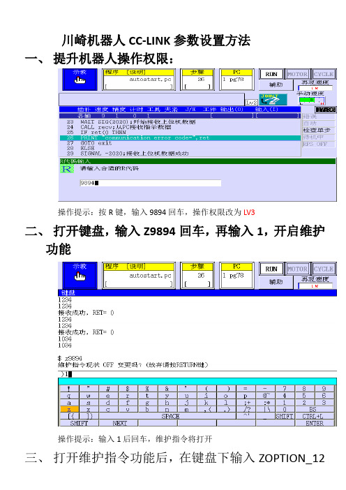
川崎机器人CC-LINK参数设置方法
一、提升机器人操作权限:
操作提示:按R键,输入9894回车,操作权限改为LV3
二、打开键盘,输入Z9894回车,再输入1,开启维护
功能
操作提示:输入1后回车,维护指令将打开
三、打开维护指令功能后,在键盘下输入ZOPTION_12
回车,按提示菜单将现场总线通信功能打开(下图第二项)
四、输入R代码060805,进入辅助功能之CC-LINK现
场网络参数设置:
操作提示:也可点击辅助—输入/输出信号—信号配置设定—CC-LINK参数设
定,一步一步进入子菜单进行参数设定
4.1 通用参数设定
4.2站数据设定:
操作提示:
我们统一规定将站数据设定为:站类型1 Ver. 2.0; 站类型2 智能设备扩展循环:4倍,占有站数:4站
4.3远程登陆数设定:
远程登录数(主从口)均设定为64
五、其它I/O物理接口分配(默认)
六、信号列顺序设定(默认)
八:其它测试数据记录:
1、经现场实测得到:当站数据设定为:Ver. 2.0, 4局4站时,每台智能设备
占用448点(BIT位),其中前256位可与主站(PLC)一一对应,256位之后暂
不能对应上(有待验证);
2、硬件上CC-LINK板卡上S2第三位拔码开关拔到1,表示4局4站;
3、站地址设定开关为10进制数字设定;
4、CC-LINK插头接线:DA、DB、DG颜色各站一一对应,FG接屏蔽线,DA,DB之间在第一个站和最后一个站时需连接一只110欧的终端电阻。
川崎泵说明书模板

03890312川崎斜板形K3V系列轴向活塞泵使用说明书株式会社川崎精機目录1.型号表示22.规格33.构造和动作原理44.使用上的注意事项64-1安装64-2配管上的注意事项74-3关于过滤网94-4动作油和温度范围114-5使用上的注意事项124-6注满油和排气124-7开始运转时的注意事项135故障的原因及处理145-1一般的注意事项145-2泵体异常的检查方法145-3马达的过载155-4泵流量的过低, 排出压力不能升高时16 5-5异常音, 异常振动16附图, 附表附图1.泵的构造图17附图2.泵的展开图18附表1.泵体装紧扭矩一览表1911.型号表示K3V112DT-1CER-9C32 – 1BS: 单泵S尺寸( 推开容积cm/rev)2.规格尺寸63 112 140 180 推开容积cm /rev 63 112 140 180压力kgf/cm MPa 额定320(31.4) 最高350(34.3)旋转数1/min最高*1 3,250 2,700 2,500 2,300自吸最高*22,600 2,200 2,000 1,850重量kg 单泵48 68 86 86 双泵81 125 160 160动作油种类耐磨性动作油温度范围-20~+95︒C粘度范围10~1,000cSt(mm /s)推荐过滤网返回线路公称尺寸10μm吸入线路80~150目滤网*1.闭路规格的最高旋转数使用闭路规格时, 请预先商谈。
*2.吸入压力0kgf/cm时的旋转数。
3。
川崎外部启动(15.12.2)
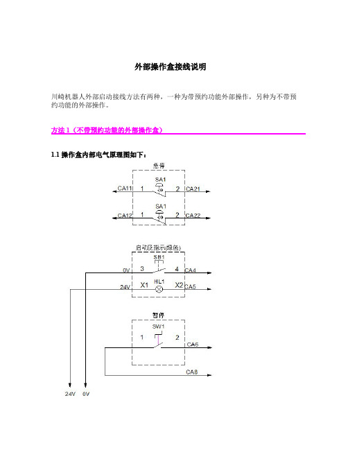
--------当工位 1 的预约按钮按下,
TWAIT 2
2s 后,
IF SIG(1001) THEN
检测工位 1 按钮是否仍然按下,
SWAIT -1001
等待工位 1 预约按钮弹起
IF shu[1]==1 THEN 当预约顺序为 1 的工位编号为 1 时,将其预约状态取消
shu[1] = shu[2]
SIGNAL -2
VALUE 3: SIGNAL -3
VALUE 4: SIGNAL -4
VALUE 0: ;
END
工位 2 预约状态灯灭 ... ... ... ... ...
机器人控制柜内部板及 PIN 定义
1GN
1GN
1GN
1GN
1GN
川崎机器人R系列安装与连接手册

4.0 机器人的搬运方法................................................... 18 4.1 使用吊绳(无底板时)................................................. 18 4.2 使用吊绳(有底板时)................................................. 19
2.0 机器人手臂安装和连接的工作流程
2. 机器人手臂安装和连接的工作流程
此流程图仅描述了机器人手臂部分。有关控制器部分,请参阅别册的控制器的“安装和连接手册”。
准
检查安装位置和机器人的 运动范围
参阅: 3. 机器人的运动范围与规格
备
工
参阅: 5. 基座的安装尺寸
作
检查和准备安装场地
6. 机器人架台的安装方法
本手册适用于如下机器人 RS05L, RS06L, RS10N, RS10L, RS20N, RS30N, RS50N, RS80N, RD80N
1. 本手册并不构成对使用机器人的整个应用系统的担保。因此,川崎公司将不会对使用 这样的系统而可能导致的事故、损害和(或)与工业产权相关的问题承担责任。
2. 川崎公司郑重建议: 所有参与机器人操作、示教、维护、维修、点检的人员,预先参 加川崎公司准备的培训课程。
川崎机器人 R 系列
安装和连接手册
川崎重工业株式会社
90202-1112DCB
R 系列 川崎机器人 安装和连接手册 前言 本手册介绍了川崎机器人 R 系列的安装与连接方法。 在进行任何操作之前,敬请全面阅读、完整理解本手册和安全手册的内容,并请一定严 格遵守所有的安全规定。本手册仅介绍机器人手臂的安装与连接。有关机器人控制器,请 参阅控制器的「安装和连接手册」。有关弧焊用机器人,请参阅弧焊用的「安装和连接 手册」。 在此反复强调,在未完全理解本书的全部内容之前,请不要进行任何操作。对于只按照 本手册中某一部分内容进行操作而导致的事故或损害,川崎公司将不负任何责任。
9020使用说明书
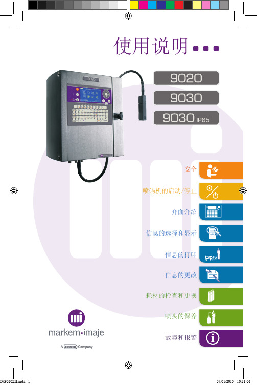
使用说明
安全
喷码机的启动/停止
介面介绍
信息的选择和显示
信息的打印
信息的更改
耗材的检查和更换
喷头的保养
故障和报警
安全
E
___________________________________________________________________________________
使用说明
安全使用说明
安全
使用说明
安全使用说明
安全
使用说明
安全使用说明
安全
使用说明
9020 - 9030 使用说明
喷码机的启动
喷码机关闭■
日常关闭
使用说明
介面介绍
信息选择■
选择喷印信息
使用说明
显示信息
使用说明
信息打印
15
“PARIS”这条信息喷印就绪
使用说明
信息的更改
使用说明
耗材
17油墨添加剂
盒内余量水平
使用说明
喷头的保养
使用说明
喷头的保养(续)清洗喷头仔细将其干燥,然后
使用说明
故障与报警
使用说明
照片和图示未在细节上结合描述。
明。
马肯依玛士保留修改产品规格的权利,恕不提前通知。
禁止以任何形式复制本文档或本文档的部分内容。
原始手册的翻译: 原始手册(法文)可从打印机随附的 CD-ROM 中获得。
使用说明
A39544-A。
fcb安装调试手册.doc

FCB型电站锅炉飞灰含碳量在线检测系统第二卷安装调试手册南京擎能自动化设备有限公司目录第一部分装置现场安装 (2)一、结构部分的安装: (2)1、测试箱与飞灰取样器安装: (2)2. 电控箱的安装: (4)3. 主机柜的安装: (4)4. 制作安装、调试用工作平台: (4)5. 制作防雨棚: (5)6. 气源要求: (5)7. 电功率要求: (5)二、电缆敷设 (5)1. 电厂→主机柜 (5)2. 主机柜→电厂 (5)3. 主机柜→电控箱 (6)4. 电控箱→测试箱(某侧烟道) (6)三、电气前期安装 (6)1. 主机柜开孔与安装(见主机柜机械安装说明)。
(6)2. 主机柜接线端子排的安装 (6)3. 电缆放置要求: (6)第二部分装置的调试 (8)1. 系统接线 (8)2.设定初始状态 (9)3. 通电检查 (9)4. 装置调试 (10)附图1:测试箱及工作平台安装尺寸图附图2:烟道壁及保温层开孔图附图3:电控箱安装尺寸图附图4:电缆敷设示意图附图5:A/B侧测试箱接线及出线图附图6:主机箱-电控箱接线及出线图第一部分装置现场安装本装置现场安装需电厂方面配合做的工作主要分为结构部分的安装和电缆的铺设和各种信号源的提供。
下面就具体内容简述如下:一、结构部分的安装:本装置结构部分由两套飞灰取样器、两套测试箱、一套电控箱和一套主机柜组成。
锅炉飞灰含碳量在线检测装置的前期现场安装工作包括以下内容:在空预器之后,除尘器之前的A、B两侧烟道上安装飞灰取样器和测试箱;在位于A、B两侧烟道的中间部位,安装电控箱;在集控室或电子间的适当位置安装主机箱;给装于A、B两侧烟道的测试箱分别提供仪用空气气源;电缆铺设:1、测试箱与飞灰取样器安装:1.1取样器和测试箱的安装要求:a.取样点位置:空气预热器之后,除尘器之前烟道的直管段。
b.温度要求:取样点处的烟道温度小于200℃。
c.流场要求:烟道内取样点附近烟道截面没有突变,气流平稳。
回旋马达减速机(M2X120B)-RG10D使用说明书.

0 2 2 9 3 6 6 6( M 2 × 1 2 0 B )— R G 1 0 D 2 0 * *使用说明书维修指导书川崎重工业株式会社精机事业部器械技术部机器科目录页1 前言 32 结构 33 使用时的注意事项 3 3.1 安装 3 3.2 齿轮油,润滑油脂 3 3.2.1 供油量 3 3.2.2 供油的品牌 3 3.2.3 齿轮油的调换建议周期 3 3.3 运转前的注意事项4 3,4 运转中的注意事项 44 故障的原因与对策 45 维修指导要领 5 5.1 注意事项 5 5.2 零件的检修要求及标准调换周期 5 5.3 分解.装配要求 7 5.3.1 所用螺栓的尺寸及旋紧的力矩 7 5.3.2 所用工具 7 5.3.3 分解.装配要求 75.3.4夹具 12 (附加资料)外型尺寸图 13 装配断面图 171 前言本齿轮马达是用于挖掘机的旋转动力开发而成的,由下述2台机器所组成。
1)油压马达M2X120B2)减速器 RG12D20**在这里主要就上述2)减速器的使用要领作一下说明。
同时,请参照油压马达的使用说明书。
2 结构基本结构见装配图。
减速器是由双层行星齿轮组成,其结构是油压马达的安装法兰兼作为减速器上部外壳。
各齿轮的齿数见下表1,整个减速比为20.04。
也就是说油压马达转速为1/20.04传送到输出轴。
输入轴与输出轴的旋转方向相同。
3. 使用中的注意事项3.1 安装本减速器的设计为马达旋转型,使用时输出端向下安装(纵向)。
安装时要注意按外形尺寸图所示的接口、排油口的位置。
旋转方向与油压马达的接口的关系见外形尺寸图,配管时要加以注意。
3.2齿轮油,润滑油脂3.2.1供油量1)齿轮油购入时供油口有塞子封住,运转前将其取下,并装上液位杆及导管。
另外,液位杆兼空气吸潮。
加油时,从外形尺寸图所指定的PT3/4注油口注油。
加油到液位杆下部的目标线,约可加3.4升。
2)润滑油脂取下外型图上所指定的排气口的柱塞,加入油脂直至从该排气口溢出为止。
ITT Model 3796 i-FRAME 安装、运行与维护手册说明书

安装和连接手册(BA006N)

将会产生偏差异常或超负荷。在这种情况下,请实施低速(通常开动速度的一半左右) 暖机运转(5-10 分钟)。) 5. 相对湿度必须在 35 % - 85 %RH 之间,无凝露。 6. 确保安装位置极少暴露在灰尘、烟雾和水环境中。 7. 确保安装位置无易燃、腐蚀性液体和气体。 8. 确保安装位置不受过大的振动影响。(0.5G 以下) 9. 确保安装位置最小的电磁干扰。 10. 确保安装位置有足够机器人运动的空间。 (1) 在机器人的周围设置安全围栏,以保证机器人最大的运动空间、即使在手臂上安
2
BA006N 川崎机器人 安装和连接手册
目次
1.0 注意事项............................................................. 4 1.1 搬运、安装和保管时的注意事项 ......................................... 4 1.2 机器人手臂的安装环境 ................................................. 5 1.3 残存危险............................................................. 6
8.0 工具安装............................................................ 17 8.1 手腕末端(法兰面)的尺寸 .............................................. 17 8.2 固定螺栓规格 ........................................................ 17 8.3 负载能力............................................................ 18
9920 Midas 中文简易操作手册

औԼ֖൘
ػՍ
҆Ս
ᱷ։ ֖൘
REFITT ALIGNI AND TU
ཐఝ
ػՍ
औԼओػՍ
4
HOW CAR
औԼओػՍ औԼओػՍ
҆Ս ҆Ս
ػՍ ػՍ
ሡ҆Ս์౸ᗨ্తཐఝ্ ሡ҆Ս์౸ᗨ্తཐఝ্
҆Ս ҆Ս
ཐఝ
ཐఝ
HOW C
TYPICAL WIRING THOUGH GLAND TYPICAL WIRING THOUGH GLAND
感測器長期處於高濃度 氣體下。
更換濾芯。
感測器基準線已經漂移。 檢查背景氣體濃度、溫度或濕度波動。實施零點校準。更換濾芯。
自上次校準後已經過太 長時間。
更換或校準濾芯。
濾芯過度老舊。
更換濾芯。
濾芯未能通過 Reflex™ 檢查。
更換濾芯。
濾芯未能穩定化。
如果存在溫度和濕度的突變情況,請預先處理濾芯。檢查背景氣體濃度。更換濾芯。
8.1. 檢查功能表「 」
檢查子功 能表
軟體 SW 警示
故障
校準
確 定
➭
確 定
➭
確 定
➭
確 定
➭
確 定
➭
確 定
✓
顯示軟體
✓ 顯示軟體加 ✓ 按下 ▲ 或 ▼
版本
總檢查碼
選擇下一功
能表,或按「
X」結束
✓
以 (X – Y)
✓
第 1 級 (L1)
✓
警示時間延
✓
警示繼電器
✓
警示繼電器
✓ 按下 ▲ 或 ▼
的格式顯示
選擇下一功
川崎机器人 R系列 手臂安装连接手册

川崎 R系列手臂安装连接手册川崎 R系列手臂安装连接手册注意事项:1:为确保安全,请在操作之前仔细阅读本手册,并确保您具备足够的操作经验;2:在进行任何操作之前,请确保断电并且所有能源源头已经关闭;3:如有任何疑问或困惑,请立即与川崎客服联系。
1:准备工作1.1 安全准备:1.1.1 工作区域:确保工作区域没有任何障碍物,并设有适当的安全控制装置;1.1.2 人员保护:在操作过程中,请确保没有其他人员靠近;1.1.3 紧急停机:应设有紧急停机装置,以便在紧急情况下立即停止机械运动。
1.2 工具和材料准备:1.2.1 手动工具:准备常用手动工具,例如扳手、螺丝刀等工具;1.2.2 连接件:根据您的实际需求,准备适当的连接件,例如螺栓、螺母等。
2:手臂安装2.1 安装位置:2.1.1 确定的安装位置,并参考的安装图纸进行布置;2.1.2 确保的安装位置平坦且不会受到明显的振动干扰。
2.2 固定:2.2.1 使用适当的螺栓和螺母将固定在所选位置上;2.2.2 确保固定牢固且稳定,以便在操作过程中不会发生突然的移动或倾斜。
2.3 识别和连接电源:2.3.1 根据的电源要求,确保提供正确的电源连接;2.3.2 注意电源线的绝缘状态,确保安全地连接电源。
2.4 连接控制系统:2.4.1 根据的控制系统要求,正确连接控制器和电气设备;2.4.2 检查连接线路,确保连接正确并牢固。
3:手臂连接3.1 连接工具和附件:3.1.1 使用适当的工具和附件,根据的要求连接末端工具;3.1.2 确保连接工具和附件的固定和稳定。
3.2 调节连接参数:3.2.1 根据的操作手册,使用相应的方法调整连接参数;3.2.2 确保连接参数适当,以获得最佳的性能。
3.3 进行连接测试:3.3.1 在连接完成后,进行连接测试以确保连接的稳定性和可靠性;3.3.2 检查连接是否正常运作,是否有任何异常或震动。
4:附件本文档涉及附件:附件1:川崎 R系列安装图纸5:法律名词及注释5.1 :指能够自主执行任务的自动化机械设备;5.2 末端工具:手臂末端的功能装置,用于执行各种操作。
2 英寸立管安装指南 - 中文说明书

*安装本产品前请认真阅读所有安装指南
*不遵本产品所造成的财产损伤或破坏,Advanced Sport Touring 公司不承担任何责任
包括行李架在内共有:一套立管,一管乐泰胶水,六个 80mm 螺栓
*一个支架,带有 10mm 与 20mm 的螺栓(仅适用于非 ABS 模式)
安装必备工具:60mm 艾伦内六角扳手,10mm 与 12mm 扳手或套筒扳手
*4mm 艾伦内六角扳手(仅适用于非 ABS 模式)
1) 在安装车把立管之前,我们需要做一些准备工作,来让刹车和离合线有足够的空间安装立管。 2) 在非 ABS 模式下,拧下将离合线导向转向头左侧的金属导线器,并将它翻转过来。确保将离合线以翻转
10)反复检查摩托车的功能是否与安装立管之前完全一致。如果您发现引擎的转速或制动器/离合器操作有任 何异常,检查一下线路是否没有接好。如有异常情况请不要发动摩托车。
11)Advanced Sport Touring 公司不承担任何责任。
后的状态放回导线器内。把这些螺栓的扭矩转到 8 英尺/磅(Fig.1)。如果您的摩托车没有如图 1 所示的 导线器,则不需要进行这项改装步骤。您可以在完成下一个步骤之后直接将线向上拉即可(Fig. 2)。 3) 要让离合线松弛以便安装这些立管,您必须将下方的三角轧头任意一端的塑料丝支架移除。您可以打开 线圈支架松弛离合线(Fig. 3.1)或将支架从三叉架上取下来(Fig. 3.2)。这些支架取下后将不会再连接 到任何地方。 4) 为了防止在下一个步骤中对摩托车的表面造成破坏,请在油箱上放一块毛巾。 5) **下一个步骤中,不要对制动手把进行充气。对制动手把充气的话会把空气带到刹车线里,这样就要对 制动器进行放气。要让刹车线更加松弛的话,就必须将刹车线接头旋转大约 1/2”。这要使用一把 12mm 的扳手或套筒扳手轻轻地将刹车线接头放松。这样做不是要旋开接头,只是将它松到足够旋转接头即 可。这些接头有可能会突然松掉。如果您松得太厉害的话,就会有一股液体开始缓缓地漏出来。少量的 液体漏出来是正常的。把刹车线接头调到如(Fig. 4)所示的位置之后,将接头的扭矩调到 16 英尺/磅。 6) 用一把 10mm 口径的扳手或套筒扳手将连接液压离合器和制动软管的方形连接件从三角轧头上旋下来。 这些连接件是一些小小的黑色方形物件,顶部和底部有一条软管(Fig. 5)。 7) 如(Fig. 6)所示分别找出左边和右边的立管。当立管位于如图所示的位置时,带线的孔必须更接近顶部 而不是底部。 8) 在三个 80mm 螺栓的螺纹下部都滴一滴乐泰胶水。由于旋动螺栓时胶水会流散,因此没有必要将胶水涂 遍整个螺栓。这些胶水能让螺栓在操作过程中不会松动。假如您在此后一段时间里需要移除这些螺栓的 话,则胶水要涂少一点。用一把 6mm 的艾伦内六角扳手将把左边车把固定到三角轧头上的三个螺栓移 除。将车把向上提起来,把左边用的立管套入三角轧头与车把中间。将您之前涂上乐泰胶水的 80mm 的 螺栓旋入。把这些螺栓旋紧至 16-18 英尺/磅(Fig. 7)。现在用备用螺栓将离合器连接件连接到刚安装好 的立管上。把这些螺栓的扭矩调到 8 英尺/磅(Fig. 8)。 9) 除了不用安装连接件以外,右边立管的安装步骤与左边一样。
同方川崎直燃机说明书

同方川崎直燃机说明书同方川崎直燃机说明书一、设备简介同方川崎直燃机是一种高效、环保的制冷设备,采用直接膨胀式制冷技术,适用于工业、商业和民用等多种领域。
该设备具有体积小、制冷量大、节能环保等优点,是现代制冷技术中的一种重要设备。
二、安装步骤1.确定安装位置,确保设备周围环境良好,无高温、强磁场等干扰源。
2.按照设备尺寸和重量,准备好相应的安装材料和工具。
3.连接电源和气源,确保连接可靠,不漏气。
4.安装冷凝器,确保其与散热器连接紧密,无渗漏。
5.安装压缩机,并将其与电动机相连,确保连接紧固。
6.安装膨胀阀和过滤器,确保连接紧固,无渗漏。
7.安装管道和阀门,确保连接紧固,无渗漏。
8.进行系统充注和调试,确保设备运行正常。
三、操作流程1.启动前检查设备周围环境是否良好,无杂物和危险物品。
2.打开电源和气源,对设备进行预热。
3.调整设备的制冷参数,确保其符合使用要求。
4.启动压缩机,让其正常运行。
5.根据需要调整设备的运行状态,确保其正常运行。
6.定期检查设备的运行状态和制冷效果,及时进行调整和维护。
四、维护保养1.定期清洗冷凝器和散热器,确保其散热良好。
2.定期更换过滤器和润滑油,确保设备正常运行。
3.定期检查管道和阀门,确保其连接紧固,无渗漏。
4.定期进行设备的调试和维护,确保其正常运行。
五、常见问题及解决方法1.设备无法启动:检查电源和气源是否连接可靠。
2.设备制冷效果不佳:清洗冷凝器和散热器,更换过滤器和润滑油。
3.设备运行异常:检查设备和管道是否有异常声音和振动。
4.设备漏气:检查气源连接是否紧固,密封圈是否完好。
六、注意事项1.操作人员必须经过专业培训,熟悉设备操作和维护流程。
2.设备运行时,禁止进行拆卸和维修。
3.设备周围禁止放置易燃、易爆物品。
4.设备运行时,禁止用手触摸设备和管道,防止发生意外事故。
七、保修条款1.本设备自购买之日起享有壹年的保修期。
2.在保修期内,因非人为因素造成的设备故障,免费维修或更换部件。
自燃器安装与操作指南说明书

IMPORTANT SAFETY INFORMATION: READ AND FOLLOW ALL INSTRUCTIONSSave these instructions. Leave manual with homeowner after installation.Improper installation, adjustment, alteration, service, or lack of maintenance can cause injury or property damage. Readthe installation, operating, & maintenance instructions thoroughly before installing or servicing this equipment.AUTO IGNITERINSTALLATION & OPERATION INSTRUCTIONSSAVE THESE INSTRUCTIONS FOR FUTURE REFERENCE®Do not install this appliance near any combustibles. A Liquid Propane cylinder not connected for use shall not be stored in the vicinity of this or any other appliance.alteration, service or maintenance can cause injury or property damage. Installer must follow all local codes as well as National Fuel Gas Code, ANSI Z223.1.If you smell gas, shut off the gas to the appliance and extinguish any open flame. If the odor lingerskeep away from appliance and immediately call gas supplier or fire department. Do not leave anyflame unsupervised.Carbon Monoxide Hazard: This appliance can produce carbon monoxide which has no odor. Usingit in an enclosed space can cause serious injury or death. Never use this appliance in an enclosedspace such as a camper, tent, car or home.HOT! DO NOT TOUCH. SEVERE BURNS MAY RESULT. CLOTHING IGNITION MAY RESULT.Glass and other surfaces are hot during operation and cool-down. CAREFULLY SUPERVISE childrennear this appliance. Alert children and adults to hazards of high temperatures.SAVE THESE INSTRUCTIONSADHERE TO ALL LOCAL CODES CONCERNING INSTALLATION AND OPERATION.• Test for gas leaks prior to use.• Verify correct gas fuel type. Never use an alternative fuel, including bio-fuel, ethanol, lighter fluid or any other fuel.• Installation must be performed by licensed gas piping professional.• When pit is not in use, turn off gas and/or power to prevent unwanted start-up.• The use of a cover when not in operation is recommended.• Verify gas shut off is located outside of the fire enclosure. The gas shutoff should NOT be used to adjust flame height.• An approved gas valve or keyed valve shall be installed upstream of the unit and located in an accessible area that is within 5ft from the unit.NOTICE It is CRITICAL that all LP units are checked for back pressure after media has been installed.Do not modify units from factory configuration. Doing so will void the warranty.NOTICE Manufacturer is not responsible for damage due to improper installation. IMPORTANT WARNINGS & SAFETY INSTRUCTIONS READ AND FOLLOW ALL INSTRUCTIONS23Installation must be performed by a licensed contractor. Installer must follow all local codes as well as National Fuel Gas Code, ANSI Z223.1. We suggest that our products be serviced annually by a professional certified in the US by the National Fireplace Institute (NFI) as NFI Gas Specialists or in Canada by WETT (Wood Energy Technical Training). Installer must follow all instructions carefully to ensure proper performance and safety.This Product is for outdoor use only.Do not modify units from factory configuration. Doing so will void the warranty.GAS REQUIREMENTSELECTRICAL REQUIREMENTS• Auto ignition requires minimum 12.6 volts DC, up to 36 Volts DC at the transformer • The included transformer steps down to 12.6 V DC•Installer should check voltage after installation to ensure proper valuesB. SYSTEM REQUIREMENTS1. AUTO IGNITION COMPONENTS• Auto Ignition Black Box: all gas and electrical connections are on the box.• Transformer: A 12.6 Volt DC transformer is pre-installed.• Probes: two probes connect to the side of the box with a quick connector. There are two probes: one for thermocouple temp sensor and one igniter.• Other Items• Air mixer: included Liquid Propane units• Pressure regulator• Shut-off valve: not includedAuto IgnitorValve BoxPanValve2. IMPORTANT INFORMATION FOR PROPANE UNITS• Air mixers required for Liquid Propane.• No elbows immediately after an air mixer. Do not attach the air mixer directly to the fire ring.• Our units are NOT intended to be used with small portable LP tanks.• For the air mixer, be sure to follow specific instructions and make sure the gas is flowing in the same direction as the arrow on the air mixer. Failure to do so could result in personal injury and damage to unit/property.45• Vent collars should not be obstructed.•Air intake holes on the air mixer should not be obstructed.3. GAS CONNECTIONa. Before beginning, ensure the gas line is turned OFF.b. NOTE: The air mixer must be installed to use liquid propane. The “holes” on the air mixer should always face DOWN,away from the burner and pan. The air mixer should be installed immediately below the burner. (FIG 2)c.Run 1/2” gas line to the bottom connection on the black boxd. Use pipe dope/joint compound on ALL threaded fittings EXCEPT flared fittings.e. Keep pipe length and elbows to a minimum to eliminate unnecessary pressure drops.f. The use of a corrugated gas line can cause unwanted noise.g. Connect pressure regulator in line before the Auto Ignitor Box. The regulator should be installed horizontally. Thedirectional arrow should point away from the gas source and towards the gas valve.h. Confirm no more than 1/2 PSI on at the regulator inlet. If pressure is too high regulator will shut off gas flow. If above1/2 PSI you can install a second regulator to reduce the pressure to 1/2 PSI before the included regulator.i. Verify all gas connections are tightened securely. ALWAYS perform leak tests and make repairs as needed. j. DO NOT daisy chain the gas lines. (See Section D)k. A shut-off valve must be installed at each fire feature or valve. The primary gas valve must be located where they canbe easily accessible so that the gas can be shut off quickly in case of an emergency.a. Power Requirements1. Auto ignition requires minimum 12.6 Volts DC, up to 36 Volts DC at the DC Converter.2. The included transformer steps down to 12.6 V DC3. Installer should check voltage after installation to ensure proper values b. Connections1. There are two wire connections on the side of the black box at the tranformer. Connect to power source usingwire nuts.2. These are DC power connections. You must match polarity when connecting. Connect red wire to red wire andblack wire to black or blue wire.3. Wrap wire nuts with electrical tape or some means to prevent moisture from getting in. Make sure wire nuts arepositioned away from the bottom of the burner assembly.4. Connect ground from incoming power to ground lug (If required by local codes)5. Do not “daisy chain” electrical lines (See Section D64. CHECK SYSTEMa. Perform all above listed safety checks before start up. Before operating smell all around the appliance area for gasodors and next to the floor because some gases are heavier than air and will settle on the floor.b. Ensure any person standing close to the fire feature is aware you will be turning the fire feature on prior to actuallyturning it on.c. Turn on the unit at the switch or control panel. The igniter should start glowing followed shortly by the gas valveopening and fire igniting.d. Allow the unit to run for approximately five minutes then turn off.e. Allow to cool down for approximately three minutes before trying to re-start. As a safety feature, the thermocouplewill not allow the unit to re-fire until it has cooled down.f. To adjust flame height, remove the silver cap on the regulator and rotate white plastic adjuster up or down. This willadjust the water column up or downD. OPERATION & MAINTENANCE1. GLASS OR ROCK FILL MEDIA• Use only approved fire glass or rock media on burners.• For LP applications, use NO MORE than 1/2” of coverage on top of burner.• Media must not cover up the holes on the side of the temp sensor, otherwise the auto ignition will not work properly. (FIG 3)• Prior to turning appliance on visually inspect fire feature to ensure debris such as leaves or other combustible material has not collected inside the feature which could burn and emit embers once the fire feature is turned on. Each burner should have a flame height of approximately 12” – 15” from the top of the pan.• Each burner should be adjusted as required so that the flame size at each burner is similar in appearance to each other.• Install decorative rock or glass on top of the “burner support” and burner assembly. Do not completely cover/obstruct the burner.3. START UPg. Perform all above listed safety checks before start up. Before operating smell all around the appliance area for gasD. OPERATION & MAINTENANCEodors and next to the floor because some gases are heavier then air and will settle on the floor.h. Ensure any person standing close to the fire feature is aware you will be turning the fire feature on prior to actuallyturning it on.i. Turn on the unit at the switch or control panel. The igniter should start glowing followed shortly by the gas valveopening and fire igniting.j. If the unit does not light the first time, there may be air in the gas line. Turn off unit and allow to sit for 30 seconds the power back on. This could potentially take two-three cycles but then should fire consistently.4. MAINTENANCE & CARE• Periodically clean the burner assembly with a wet cloth or cleaning solution to remove carbon build-up. Frequency of the cleaning will depend on usage.• Periodically inspect the underside of the burner assembly for any signs of excessive temperatures.• Keep the ignition and temperature probe locations clear of media or debris.• Check that all gas connections are tight.• The burner assembly should be covered and protected from snow and ice. The burner should not be operated in high wind conditions.• Visually inspect burner holes for debris/insect infestation Clean burners as necessary using compressed air.• Use the system! If the feature has been inactive for an extended period, turn fire feature on to ensure properoperation.• Inspect the gas line regularly. If the line shows evidence of excessive abrasion or wear or if the line is damaged, it must be replaced before use.• Inspect the burner before each use of the appliance. If there is any evidence that the burner is damaged, it mustreplaced before operating.• If any repairs are required, contact a licensed professional.COMMON ISSUES/MISTAKES• Check line connections - do not daisy chain gas or electrical connections (see Section C)78• Check gas pressure for natural gas and propane (see Section B)• If using with propane gas - ONLY use with air mixer correctly installed. (See Fig 2) ½ “ air mixer for propane includes stamped marking for gas flow direction. Air mixer is not required with Natural Gas. • Check electrical voltage. Minimum volts at the transformer connection is 12.6 VDC.• Check electrical connections. Auto ignitor uses DC power. Connect positive/red to positive/red/brown and negative/black to negative/black/blue.• Check ground connections. (if required)• Upon completing the gas line connection, a small amount of air will be in the lines. When first lighting the burner, it will take a few minutes for the lines to purge themselves of this air. Subsequent lighting of the appliance should not require such purging. c. LED Indicators1. There are three LED indicators on the side of the valve next to the probe connection2.The LED indicators are an obsolete component and can be disregardedDO NOT DAISY CHAIN DO RUN INDIVIDUAL LINESFIGURE 5: DAISY CHAIN GUIDEHOW TO PERFORM A LEAK TESTa. Prepare a leak testing solution of soapy water by mixing in a spray bottle one part liquid soap to one part water.b. Make sure all the control knobs are in the OFF position.c. Turn on the gas.d.Apply the leak-testing solution by spraying it on joints of the gas delivery system. Blowing bubbles in the soap solution indicates that a leak is present.e. Stop a leak by tightening the loose joint or by replacing the faulty part with a replacement part recommended by themanufacturer.f. Turn the control knob back to the full OFF position.g. If you are unable to stop a leak: Please consult a gas specialist. Shut off the gas supply to the fire pit and releasepressure in the hose and manifold. Call/consult an authorized gas appliance service technician or an liquid propane gas dealer. Do NOT use the appliance until the leak is corrected.Perform a leak test at least once a year whether the gas supply has been disconnected or not. Whenever any part of the gas system is disconnected or replaced, perform a leak test. As a safety precaution, remember to always leak testyour fire pit outdoors in a well-ventilated area. Never smoke or permit sources of ignition in the area while doing a leak test. Do not use a flame, such as a lighted match to test for leaks.9NOTES 10NOTES11SAVE THESE INSTRUCTIONSRecord Information on this System Below & Keep for Your Records Installer _______________________________________________________________ System Purchased From ______________________________________________ Installation Date _____________________________Serial Number _______________________________。
电器说明书:KOBE Range Hood 安装和操作指南

KOBE Range Hoods Brillia SeriesISX21 SQB-2 SeriesModel No.RAX9430SQB-2 (30”)RAX9430SQB-DC30-2 (30”) RAX9430SQB-DC47-2 (30”)RAX9436SQB-2 (36”)RAX9436SQB-DC30-2 (36”) RAX9436SQB-DC47-2 (36”)INSTALLATION INSTRUCTIONS AND OPERATION MANUALREAD BEFORE INSTALLATION1. Carefully check all contents of package(s).2. Thoroughly inspect the unit for any shipping damages, cosmeticdamages or defects.3. Have a certified contractor/electrician test the unit before installation. IF THERE IS ANY PROBLEM:1. DO NOT INSTALL THE UNIT AND KEEP ALL ORIGINALPACKAGING MATERIAL.2. Have your original invoice as proof of purchase and product serialnumber ready.3. Contact your merchant for product replacement due to shippingdamages, cosmetic damages or defects.4. For all other issues, email ***********************************or call 1-626-775-8880, toll free 1-877-289-5623.1.2.3.[ENGLISH]- READ AND SAVE THESE INSTRUCTIONS -CONTENTSIMPORTANT SAFETY INSTRUCTIONS (1)COMPONENTS OF PACKAGE (3)INSTALLATION (4)OPERATING INSTRUCTIONS (7)MAINTENANCE (8)SPECIFICATIONS (9)MEASUREMENTS & DIAGRAMS (10)PARTS LIST (11)CIRCUIT DIAGRAM (13)TROUBLE SHOOTING (14)WARRANTY (15)WARRANTY INFORMATION FORM (17)- READ ALL INSTRUCTIONS CAREFULLY BEFORE STARTING -A L L W I R I N G M U S TB E D O N E B Y A P R O F E S S I O N A L A N D I NA C C O R D A N C E W I T H N A T I O N A L A N D L O C A L E L E C T R I C A L C O D E S- PLEASE READ THIS SECTION CAREFULLY BEFORE INSTALLATION - WARNING:TO REDUCE THE RISK OF FIRE, ELECTRIC SHOCK OR PERSONAL INJURY, OBSERVE THE FOLLOWING:1) Installation and electrical wiring must be done by qualified professionals and in accordance with allapplicable codes and standards, including fire-rated construction.2) When cutting or drilling into wall or ceiling, be careful not to damage electrical wiring or other hiddenutilities.3) Ducted fans must be vented to the outside.a) Before servicing or cleaning unit, open the light panel and SWITCH POWER OFF AT SERVICEPANEL.b) Clean all grease laden surfaces frequently. To reduce the risk of fire and to disperse air properly,make sure to vent air outside. DO NOT vent exhaust air into wall spaces, attics, crawl spaces or garages.NOTE-This warranty is void without an authorized agent’s receipt or if unit isdamaged due to misuse, poor installation, improper use, mistreatment,negligence or any other circumstances beyond the control of KOBERANGE HOODS authorized agents. Any repair carried out without thesupervision of KOBE RANGE HOODS’ authorized agents willautomatically void the warranty.-KOBE RANGE HOODS will not be held responsible for any damages topersonal property or real estate or any bodily injuries whether causeddirectly or indirectly by the range hood.WARNING:TO REDUCE THE RISK OF PERSONAL INJURY IN THE EVENT OF A RANGE TOP GREASE FIRE:1. Keep all fan, baffle/spacer/filter/oil tunnel/oil container and grease-laden surfaces clean. Greaseshould not be allowed to accumulate on fan, baffle/spacer/filter/oil tunnel/oil container.2. Always turn hood ON when cooking.3. Use high settings on cooking range ONLY when necessary.4. Do not leave cooking range unattended when cooking.5. Always use cookware and utensils appropriate for the type and amount of food prepared.6. Use this unit only in the manner intended by the manufacturer.7. Before servicing, switch power off at service panel and lock service panel (if possible) to preventpower from switching on accidentally.8. Clean ventilating fan frequently.What to Do In The Event Of a Range Top Grease Fire•SMOTHER FLAMES with a tight fitting lid, cookie sheet, or metal tray, and then turn off the burner.KEEP FLAMMABLE OR COMBUSTIBLE MATERIAL AWAY FROM FLAMES. If the flames do not go out immediately, EVACUATE THE AREA AND CALL THE FIRE DEPARTMENT or 911.•NEVER PICK UP A BURNING PAN – You May Get Burned.•DO NOT USE WATER, including wet dishcloths or towels – a steam blast will result.•Use an extinguisher ONLY if:a) You have a Class A, B, C extinguisher and know how to operate it.b) The fire is small and contained in the area where it started.c) The fire department has been called.d) You can fight the fire with your back to an exit.What to Do If You Smell Gas- Extinguish any open flame.- Do not try to turn on the lights or any type of appliance.- Open all doors and windows to disperse the gas. If you still smell gas, call the Gas Company and Fire Department right away.CAUTION1) For general ventilation use only. Do not use to exhaust hazardous or explosive materials and vapors.2) To reduce the risk of fire, use only metal ductwork. Sufficient air is needed for proper combustion andexhausting of gases through the flue (chimney) to prevent back drafting.3) Follow the heating equipment manufacturer’s guideline and safety standards such as those publishedby the National Fire Protection Association (NFPA), and the American Society for Heating, Refrigeration and Air Conditioning Engineers (ASHRAE), and code authorities.4) Activating any switch on may cause ignition or an explosion.5) Due to the size and weight of this hood, installation by 2 persons is recommended.ELECTRICAL SHOCK HAZARD –Can result in serious injury or death.Disconnect appliance from electric power before servicing. If equipped,the fluorescent light bulb contains small amounts of mercury, which mustbe recycled or disposed of according to Local, State, and Federal Codes.CONTENTS OF PACKAGE(Must keep all material for returns or refunds)RAX94 SQB-2 Series Range Hood Box{A} Range Hood Body – 1 {B} 2-pc Duct Cover – 1{C} Duct Cover Mounting Bracket – 2 {D} Warranty Registration Card – 1 {E} Quick Reference Guide – 1 {F} Baffle Filters x 2 (30” hood)x 3 (36” hood){G} 6” Round Vent Adapter (for vertical venting) {H} Aluminum Duct Pipe {I} Flapper (2 pcs) {J}Screw Package{A}{B} {C}{D} {E}{F} {G}{H} {I} {J}RAX94DC30-I (1-piece Inner Duct Extension) (Included in RAX94 SQB-DC30-2 only){K} 1-piece Inner Duct ExtensionModel No.: RAX94DC30-I{K}RAX94DC47-I (1-piece Inner Duct Extension) (Included in RAX94 SQB-DC47-2 only){L} 1-piece Inner Duct ExtensionModel No.: RAX94DC47-I {L}⧫ FOR MORE INFORMATION, PLEASE VISIT OUR WEBSITE .Inner duct cover Outer duct cover 4 x 8 mm QTY: 6 PCS(Pre-attached to Vent Adapter) 4 x 35 mm QTY: 6 PCS 12 x 40 mm QTY: 6 PCS(For sheet rock only) 5 x 12 mm QTY: 6 PCS Pre-attached to Vent AdapterPLEASE READ ENTIRE INSTRUCTIONS BEFORE PROCEEDINGCalculation before InstallationTo calculate installation, please refer to TABLE 1 (all calculations are in inches.)- FOR WALL MOUNT -SAFETY WARNING•HOOD MAY HAVE SHARP EDGES; PLEASE WEAR PROTECTIVE GLOVES IF REMOVING ANY PARTS FOR INSTALLING, CLEANING, OR SERVICING.•BE CAREFUL WHEN USING ELECTRICAL SCREWDRIVER, DAMAGE TO THE HOOD MAY OCCUR. USING HAND TOOLS IS RECOMMENDED. DO NOT OVER TIGHTEN SCREWS.•MAKE SURE TO PREVENT ANY DEBRIS FROM ENTERING THE VENT OPENING TO AVOID DAMAGE OR MALFUNCTION.WALL MOUNT INSTALLATION**Installation videos available at **1. Read any provided document(s).2. Test the range hood by temporarily connecting to an outlet and turning ON the fan and lights.3. If you run into any problems, contact KOBE Range Hoods.4. This range hood h as top 6” round exhaust.5. Decide the location of the venting pipe from the hood to the outside. A straight, short vent run willallow the hood to perform more efficiently. Try to avoid elbows, transitions, and long run as much as possible as this may reduce the performance of the hood. Make sure that the duct work leads to the outside.6. It is recommended to use metal/aluminum duct/pipe with auniform size (ex. 6” round pipe from range hood to the outside). 7. If an elbow is necessary, a minimum of 12” straight run isnecessary before the elbow.8. Clearance is the distance between the cooktop and the bottomof the range hood. The recommended minimum clearance for this model is 26” and the maximum clearance is 30”.9. It is important to install the hood at the recommendedclearance. Installing too low could result in damage and/or fire hazard while installing too high may result in reduced performance and efficiency.10. The first step is to secure the mounting screws on the wall. Itis important that the screws are hitting the wall studs. If necessary, install a cross lumber frame in the wall as shown in figure 1.11. Attach the mounting screws on the wall, leaving about 1/8 ofan inch between the wall and the end point of the screws since this is where you will hang your hood. Refer to figure 2.12. Align the hood-mounting bracket to the screws on the wall andhook into place. Then tighten the screws to secure the hood to the wall.CAUTION : MAKE SURE THE HOOD IS SECUREBEFORE RELEASING.13. Attach the vent adapter to the exhaust opening using the 4 x 8mm screws.14. Connect the pipe onto the vent adapter and seal the joint withduct tape. Make sure that it is completely air tight.15. Attach the two duct cover mounting bracket on the wall as seenon figure 4.16. Place the inner duct cover and outer duct cover over the rangehood.17. Secure the outer duct cover to the range hood body with the 5 x 12 mm screws provided.18. Pull the inner duct cover up until it aligns properly to the ductcover mounting bracket, then secure to the duct cover mounting bracket with 5 x 12 mm screws. Refer to figure 3 and 4.19. Connect the range hood to an outlet.20. If hardwired is desired, cut off the plug and connect three wires(black, white, green) to the outlet wires and cap with wire connectors. Connect the wires according to color (ex: black to black).ClearanceHood Installation DuctworkDuct CoverElectrical WireFigure 1 Figure 2Figure 3Figure 4Duct Cover Mounting Bracket21. Remove any protective film off the hood, if any.22. Before using, make sure that any accessories such as filters are properly installed whereapplicable.23. Test the range hood to see if it is working properly.THIS RANGE HOOD MUST BE PROPERLY GROUNDED. MAKE SURE THIS IS DONE BY QUALIFIED ELECTRICIAN IN ACCORDANCE WITH ALL APPLICABLE NATIONAL AND LOCAL ELECTRICAL CODES. BEFORE CONNECTING WIRES, SWITCH POWER OFF AT SERVICE PANEL AND LOCK SERVICE PANEL TO PREVENT POWER FROM BEING SWITCHED ON ACCIDENTALLY.3-Speed Mechanical ControlNote: For best results, turn fan on prior to any preparation or cooking and keep fans running while cooking. Adjust speed as necessary.Button ControlOFF = Turns the range hood OFF.Q = Lowest fan speed (QuietMode).L = Middle fan speed (Low).H = Highest fan speed (High).= Turns the lights ON/OFF.Power ControlTo turn the hood off, press the OFF button once while it is ON.Speed ControlPress the speed buttons (Q, L, and H) to increase/decrease the fan speed level.Light ControlPress the light button to turn ON/OFF the lights.For optimal performance, clean the range hood surface and baffles regularly.To Clean Hood SurfaceCAUTION: NEVER USE ABRASIVE CLEANERS, PADS, OR CLOTHS.*** Regular care will help preserve its fine appearance.1. Use only mild soap or detergent solutions. Dry surfaces using soft cloth.2. If hood looks splotchy (stainless steel hood), use a stainless steel cleaner to clean the surface ofthe hood. Avoid getting cleaning solution onto or into the control panel. Follow directions of the stainless steel cleaner. Caution: Do not leave on too long as this may cause damage to hood finish. Use soft towel to wipe off the cleaning solution, gently rub off any stubborn spots. Use dry soft towel to dry the hood.3. DO NOT allow deposits to accumulate or remain on the hood.4. DO NOT use ordinary steel wool or steel brushes. Small bits of steel may adhere to the surfaceand cause rusting.5. DO NOT allow salt solutions, disinfectants, bleaches, or cleaning compounds to remain in contactwith stainless steel for extended periods. Many of these compounds contain chemicals, which may be harmful. Rinse with water after exposure and wipe dry with a clean lint free cloth.For Baffle Filter models only: to Clean Baffle Filter/Oil TunnelCAUTION: DRAIN OIL FROM BAFFLE FILTERS, SPACERS & OIL TUNNEL REGULARLY TO PREVENT OVERFLOW.1. Remove all the baffle filters, spacers and oil tunnel. Note: Not all models have spacers and oiltunnels.2. Using a sponge, wash with warm soapy water. Dry completely before returning into place.CAUTION: SHARP EDGES (Note: Baffle Filters are top rack dishwasher safe.)MODEL / SIZE For 30” model For 36” modelRAX9430SQB-2 RAX9436SQB-2RAX9430SQB-DC30-2 RAX9436SQB-DC30-2RAX9430SQB-DC47-2 RAX9436SQB-DC47-2 MATERIAL 20-Gauge Commercial Grade Stainless SteelCONSUMPTION / AMPERE 120W / 2.5ANUMBER OF BLOWER 1DESIGN Seamless / Satin FinishBLOWER TYPE Single Horizontal Squirrel CageEXHAUST Top:6" Round (available only with a 6” Round Vent Adapter [provided]) CONTROLS Mechanical Push Button (3-Speed)LIGHTS 3-watt LED light x 2HOOD BODY DIMENSION (W x D x H) RAX9430SQB-2 / RAX9430SQB-DC30-2 / RAX9430SQB-DC47-2 29-3/4” x 20-1/2” x 12-3/16”RAX9436SQB-2 / RAX9436SQB-DC30-2 / RAX9436SQB-DC47-2 35-1/4” x 20-1/2” x 12-3/16”DUCT COVER DIMENSION (W x D x H)** Standard Duct Cover (2 pc. adjustable)RAX94DC-2 10-5/8” x 7-15/16” x (16-1/8” ~ 30-5/16”)Inner Duct Extension (1 pc. - Replaces Standard Inner Duct Cover) RAX94DC30-I 10-5/8” x 7-15/16” x (30-3/16” ~ 44-5/8”) Duct Extension Set (1 pc. - Replaces Standard Inner Duct Cover) RAX94DC47-I 10-5/8” x 7-15/16” x (47-11/16” ~ 62-3/16”)HOOD WEIGHT (lbs)***Net Gross RAX9430SQB-2 (30”)39.0 49.0 RAX9436SQB-2 (36”)42.0 54.0SPEED QuietMode™Low High Air Capacity (CFM) 280 450 680 Sone* (dB) 1.0 (40) 2.2 (51) 5.0 (63) *One sone is equivalent to the sound of a refrigerator at 40 decibels.**Duct cover height when duct cover is installed.***Hood weight includes standard duct cover.****Specifications subject to change without notice.MEASUREMENTS & DIAGRAMS***All inch measurements are converted from millimeters. Inch measurements are estimated. ***All measurements in ( ) are millimeters.MODEL NO.: RAX9430SQB-2 (30”)RAX9436SQB-2 (36”)MODEL NO.: RAX9430SQB-DC30-2 / RAX9436SQB-DC30-2MODEL NO.: RAX9430SQB-DC47-2 / RAX9436SQB-DC47-2Extension Duct CoverRAX94DC30-I* For the diagram of hooddimension, please refer toPage 9.Extension Duct CoverRAX94DC47-I* For the diagram of hood dimension, please refer to Page 9.MODEL NO.:RAX9430SQB-2 (30”)RAX9430SQB-DC30-2 (30”) RAX9430SQB-DC47-2 (30”)RAX9436SQB-2 (36”)RAX9436SQB-DC30-2 (36”) RAX9436SQB-DC47-2 (36”)MODEL NO.:RAX9430SQB-2 (30”)RAX9430SQB-DC30-2 (30”) RAX9430SQB-DC47-2 (30”)RAX9436SQB-2 (36”)RAX9436SQB-DC30-2 (36”) RAX9436SQB-DC47-2 (36”)MODEL NO.:RAX9430SQB-2 (30”)RAX9430SQB-DC30-2 (30”)RAX9430SQB-DC47-2 (30”)RAX9436SQB-2(36”)RAX9436SQB-DC30-2 (36”) RAX9436SQB-DC47-2 (36”)WARRANTY CERTIFICATEIn order to obtain warranty service, you must provide proof of original purchase from a KOBE authorized Dealer. Please keep a copy of your original invoice as proof of purchase.ONE-YEAR LIMITED LABOR WARRANTY ON KOBE BRILLIA SERIES:For one year from the date of your original invoice from a KOBE authorized dealer, we will repair any parts or components free of charge that failed due to manufacturing defects. KOBE reserves the right to replace, rather than repair the product free of charge at our sole discretion.It is your sole responsibility to ensure the product is readily accessible for the service technician to perform repairs. The service technician will not, under any circumstance, remove, alter or modify any fixture built around and/or connected to the product to gain access to perform repairs.TWO-YEAR LIMITED PARTS WARRANTY ON KOBE BRILLIA SERIES:For two years from the date of your original invoice from a KOBE authorized dealer, we will provide non-consumable replacement parts or components free of charge that failed due to manufacturing defects. Consumable parts such as lights bulbs, filters, fuses, and oil cups are not covered by this warranty.WHAT IS COVERED:This warranty is valid in the United States and Canada. It is non-transferable and applies only to the original purchaser and does not extend to subsequent owner of this product. In Hawaii, Alaska and Canada, this warranty is limited. There may be additional shipping charges for parts and service technician travel costs in remote areas or locations 30 miles outside of KOBE authorized service area.WHAT IS NOT COVERED:1. Normal wear and tear, regular service and maintenance required for the product.2. Consumable parts such as light bulbs, filters, fuses, and oil cups.3. Chips, scratches or dents due to abuse or misuse of the product, use of corrosive andabrasive cleaning products.4. Damages caused by accident, fire, flood and other Acts of God.5. Services in remote areas or locations 30 miles outside of KOBE authorized service area.6. Labor cost incurred in connection with the removal of range hood, and reinstallation ofreplacement range hood, nor does it cover any other contingent expenses.7. Scratches inside the hood, back of the baffle filter, and inside the duct cover.THIS WARRANTY WILL BE VOIDED WHEN:1. Improper installation and failure to follow installation instructions.2. Any repair, alteration, modification not authorized by KOBE.3. Duct alteration, modification and connection.4. Incorrect electric current, voltage or wiring.5. Improper usage of the product such as commercially, outdoor or other usage other thanits intended purpose which is residential indoor usage only.6. Product is purchased from an unauthorized KOBE dealer.7. Product is damaged due to negligence, misuse, abuse, accident.If we determine that the warranty exclusions listed above applies or if you fail to provide all necessary documentation for warranty service, you will be responsible for all expenses associated with the requested service, including parts, labor, shipping, travelling, and any other expense related to the service request.TO REQUEST WARRANTY SERVICE, PLEASE CONTACT KOBE RANGE HOODS SERVICE CENTER:From the 48 contiguous states:Email (best): ***********************************Phone: 1-626-775-8880Toll Free: 1-877-BUY-KOBE (289-5623)From Alaska, Hawaii, and Canada:Email (best): ***********************************Phone: 1-626-775-888018KOBE Range Hoods11775 Clark StreetArcadia, CA 91006 USA VER.190911Information subject to change without notice.。
产品接头和安装说明书

5FRL101 Rev. DGlobal Air Preparation SystemMounting Bracket ConsoleEinbauhalterung Staffa di montaggioUK FR CN DE IT JP KR Sujeción de montaje ES Monteringskonsol SEP31KA00MWP31 MiniP33KA00MRP31 MiniAngle BracketÉquerreWinkelhalterung Staffa angolareUK FR CN DE IT JP KRSujeción angulada ES VinkelklammaSEP32 Compact P33 Standard P32KB00MR P31KB00MRPanel Mounting Ring Écrou pour montage sur panneau Schalttafel-SchraubringAnello di montaggio su pannelloUK FR CN DE ITP32KA00MP P33KA00MMP33 StandardP31KA00MP P33KA00MPP31KA00MM P32KA00MM Plastic Nut Écrou en plastique Kunststoffmutter Dado in plasticaTuerca plástica UK FR CN DE IT JP KR ES SEPlastmutter Metal NutÉcrou métallique Metallmutter Dado in metalloTuerca metálica Metallmutter UK FR CN DE IT JP KR ES SEP31 Mini P32 CompactJP KR Aro de montaje en panel ES Ring för panelmonteringSEIndividual Product Brackets UK JP Separata klammorSE CNÉléments de fi xation pour produits isolés FR KRSujeciones producto individual ES Spezielle Produkthalterungen DE Staffe separateIT P33 StandardP32 Compact P32KA00ML P33KA00MLL-Bracket ÉquerreWinkelhalterung Staffa angolareUK FR CNDE IT JP KR Sujeción anguladaES VinkelklammaSERégler la pression P2 et retirer le bouton du régulateur, enclencher le bouton falsifi er la preuveen placeSet P2 pressure and remove regulator knob, snap tamperproof knob in placeStellen P2 Druck und entfernen Reglerknopfes schnappen manipulationssicher Knopf an Ortund StelleImpostare la pressione P2 e rimuovere la manopola di regolazione, far scattare la manopola prova dimanomissione in attoAjuste la presión P2 y quitar la perilla del regulador, encaje manipular mando de la prueba en el lugarStäll P2 tryck och ta bort regulator knopp, knäpp manipulationssäker ratten på platsUK FR CNDE IT JP KRES SE P31 Mini P32 Compact P32KB00ALP31KB00AL P31 Mini P32 CompactP32KB00ATP31KB00AT ⸘孔㞾㩅◤₹ℶ❐㞾㩅槱㨎⸘孔婉㹜⫠㠨婉㹜摠⻭婉㹜屡㩅屡㩅Par Moment3.7 Nm (33 lbf-in)3.5 Nm (31 lbf-in)Drehmoment CoppiaTorqueCouple 㓼䩸幍⸩3 䤓☚┪᧨䲊忿庒唑㡚朽᧨⺕棁买㟈㡚朽㓲Ⓙ⇜㻯䝤䝷䜿䝑䝖ḟഃ䛾ᅽຊ䜢タᐃ䛧䚸䝺䜼䝳䝺䞊䝍䛾䝜䝤䜢ྲྀ䜚እ䛧ᅛᐃ䜻䝑䝖䜢⤌䛡䜎䛩䚹㻸䝤䝷䜿䝑䝖እወኌ䜰䞁䜾䝹䝤䝷䜿䝑䝖䝥䝷䝇䝏䝑䜽䝘䝑䝖䜰䝹䝭䝙䜴䝮䝘䝑䝖ኮኪወኻኃዐእዐኍ༢య⏝䝤䝷䜿䝑䝖䝉G㼜⺴G⽀⢰䁇㉘㥉GwYG㚉⥙G㦤㤼G䚬☘㡸G㥐ᶤS 㣙㋀㜄G㦤㣅Gⵝ㫴G㋄㣕㢨G㏘⇹㡔⏼䏬GᵐⷸG㼜⺴G⽀⢰䁇䑄≠G⫼㟨䐹G≏䏬䙀⢰㏘䐥G≏䏬≘䇼G≏䏬sG䝉G㼜⺴G⽀⢰䁇GsG䝉G㼜⺴G⽀⢰䁇G䋔⪨䆠。
902组装步骤说明.
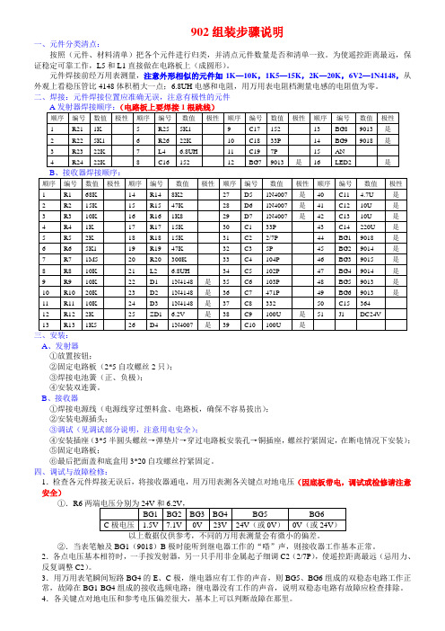
902组装步骤说明一、元件分类清点:按照(元件、材料清单)把各个元件进行归类,并清点元件数量是否和清单一致。
为使遥控距离最远,保证稳定可靠工作,L5和L1直接做在电路板上(成圆形)。
元件焊接前经万用表测量,注意外形相似的元件如1K—10K,1K5—15K,2K—20K,6V2—1N4148,从外观上看稳压管比4148体积稍大一点;6.8UH电感和电阻,用万用表电阻档测量电感的电阻值为零。
二、焊接:元件焊接位置应准确无误,注意有极性的元件A、发射器①放置按钮;②固定电路板(2*5自攻螺丝2只);③焊接电池簧(正、负极);④安装双连簧。
B、接收器①焊接电源线(电源线穿过塑料盒、电路板,确保不容易拔出);②安装电源插头;③调试(见调试部分说明,注意用电安全);④安装插座(3*5半圆头螺丝→弹垫片→穿过电路板安装孔→铜插座,螺丝拧紧固定,在断电情况下安装);⑤固定电路板;⑥最后把面盖和底盒用3*20自攻螺丝拧紧固定。
四、调试与故障检修:1.检查各元件焊接无误后,将接收器通电,用万用表测各关键点对地电压(因底板带电,调试或检修请注意安全)①.R6②.当表笔触及BG1(9018)B极时能听到继电器工作的“嗒”声,则接收器工作基本正常。
2.各点电压基本相符时,一手按发射器,另一只手用非金属起子细调C2(2/7P),使遥控距离最远(忌用力、反复调整C2)。
3.用万用表笔瞬间短路BG4的E、C极,继电器应有工作的声音,则BG5、BG6组成的双稳态电路工作正常,故障在BG1-BG4组成的接收选频电路;继电器没有工作的声音,说明双稳态电路有故障应检查排除。
4.各关键点对地电压和参考电压偏差很大,基本上可以判断故障在那里。
Kawasaki B-Series线上扭筒愿景机器人说明书

ApplicationsCarried Spot Welding Pedestal Spot Welding Material HandlingThe B-Series line of body shop robots were developed using Kawasaki’s proven advanced technology and extensive automotive experience to take performance to the next level. The robust, yet lightweight slim design achieves the sought after optimization of functionality, flexibility and investment efficiency for maximum spot welding effectiveness and multi-purpose use.HIGH SPEED SPOT WELDINGMinimized net weight, heavy-duty motors and advanced motion control technology make the B Robot a champion sprinter. It excels at high speed short-pitch movements making it ideal for spot welding. The improved motion sequence by the servo welding guns, as well as the automatic calibration feature to optimize acceleration and deceleration of the gun speed, leads to a significant reduction in cycle time and results in maximum production.SPACE SAVING DESIGNCompared to conventional robots with similar payload capacity, the B Robots have a much smaller footprint and narrower body. The small footprint of these slim arm design robots allows for installation in “high-density” applications without impeding performance. In addition, the B-Series robot line houses the cable harnesses within the robot arm, further reducing the amount of work space required and minimizing potential interference.WIDE WORK ENVELOPEThe Kawasaki B Robot combines a long reach arm with a minimal amount of dead space for a wide work envelope and greater flexibility. Kawasaki Robotics’ years ofautomotive experience have culminated into an optimal body shop design for both task effectiveness and multi-purpose usage.INTEGRATED DRESS PACKAGEThe B-Series robot line is manufactured using hollowreduction units for the upper arm. This allows for an internal dressing of the robot from the base to the tool mounting plate. With Kawasaki’s integrated dress package, the manufacturing line build and digital engineering time is greatly reduced and interference with adjacent robots or peripheral devices is minimized.HIGH QUALITY & LOW-MAINTENANCEB Robots boast industry leading reliability and 10,000 hours maintenance intervals, which translate to low operating costs and the highest production efficiencies.PROTECTION FROM HARSH ENVIRONMENTSB-Series Robots can operate in some of the harshest environments due to the Kawasaki sealed arm design.Robot maintenance due to contamination can be eliminated.OPTIMIZEDBODY SHOP ROBOTSKawasaki Robotics (USA), Inc.United States28140 Lakeview Drive Wixom, Michigan 48393Phone (248) 446-4100*********************JT1Note: Detailed drawings are available upon request.Assembly • Cutting • Dispensing • Grinding • Handling • Inspection • Packaging • Painting • Palletizing • Polishing • Tending • WeldingCanadaPhone (905) 304-7784MexicoPhone (52) 33-3110-1895BX100L - REV01/14© Kawasaki Robotics (USA), Inc. All rights reserved.Technical specifications subject to change without notice.。
- 1、下载文档前请自行甄别文档内容的完整性,平台不提供额外的编辑、内容补充、找答案等附加服务。
- 2、"仅部分预览"的文档,不可在线预览部分如存在完整性等问题,可反馈申请退款(可完整预览的文档不适用该条件!)。
- 3、如文档侵犯您的权益,请联系客服反馈,我们会尽快为您处理(人工客服工作时间:9:00-18:30)。
1. 注意事项
夹伤的危险位置
12
B 系列 川崎机器人 安装和连接手册 2.0 机器人手臂安装和连接的工作流程
2. 机器人手臂安装和连接的工作流程
此流程图仅介绍了机器人手臂部分。 有关控制器部分, 请参阅控制器的 《安装和连接手册》。
检查安装位置和机器人的 运动范围
参阅:3. 机器人的运动范围与规格 参阅: 5. 基座的安装尺寸 6. 运转过程中作用于安装面上的 运动反作用力 7. 安装方法 参阅:4. 机器人的搬运方法 参阅: 5. 基座的安装尺寸 6. 运转过程中作用于安装面上的 运动反作用力 7. 安装方法 参阅:8. 工具安装
[ 注 意 ] 表示关于机器人规格、处理、示教、操作和维护 的注意信息。
!
警 告
1. 本手册给出的图表、顺序和详细解释可能并不绝对正确。所以,在使用 本手册去做任何工作时,有必要投以最大的注意力。一旦出现未说明的 问题或麻烦,请与川崎公司联系。 2. 本手册中有关个案的安全描述,并不完全适用于所有的机器人工作。为 保证每项工作的安全, 请阅读并完整理解安全手册和相关的法律、 法规、 法令及其相关资料中各种有关安全的解释和描述, 同时请为各项工作采 取合适的安全措施。
!
小 心
1. 因为机器人机身是由精密零件组成的,所以在搬运时,务必避免让机器 人受到过分的冲击和振动。 2. 用起重机和叉车搬运机器人时,请事先清除障碍物等,以确保安全地搬 运到安装位置。 3. 搬运及保管机器人时, (1) 保持环境温度在-10 C - 60 C 内。 (2) 保持相对湿度在 35 % - 85 %RH 内(无凝露)。 (3) 避免过分的振动和冲击。
9
B 系列 川崎机器人 安装和连接手册 夹伤的危险位置(BX100N)
1. 注意事项
夹伤的危险位置
10
B 系列 川崎机器人 安装和连接手册 夹伤的危险位置(BX100L, BX130X, BX165N, BX165L, BX200L)
1. 注意事项
夹伤的危险位置
பைடு நூலகம்
11
B 系列 川崎机器人 安装和连接手册 夹伤的危险位置(BT200L)
5
B 系列 川崎机器人 安装和连接手册 1.2 机器人手臂的安装环境
1. 注意事项
请把机器人手臂安装在满足以下条件的地方。 1.当安装在地面上时,请确保地面的水平度在±5以内。 2.确保地面和安装座有足够的刚度。 3.确保平面度以避免机器人基座部分受额外的力。(如果平面度实在达不到,请使用衬垫 把平面度调整。) 4.工作环境温度必须在 0C - 45C 之间。(由于低温启动时,油脂,齿轮油的粘性大,将 会产生偏差异常或超负荷。在这种情况下,请实施低速暖机运转。) 5.相对湿度必须在 35% - 85% RH 之间,无凝露。 6.确保安装地方极少暴露在灰尘、油、烟雾和水环境中。 7.确保安装地方无易燃、腐蚀性液体和气体。 8.确保安装地方不受过大的振动影响。(0.5 G 以下) 9.确保安装地方最小的电磁干扰。 10.确保安装地方有足够机器人运动的空间。 (1) 在机器人的周围设置安全围栏,以保证机器人最大的运动空间,即使在手臂上安 装工具和工件也不会和周围的机器产生干扰。 (2) 安全围栏的出入口尽量要少(最好 1 处),并设置带安全插销的安全门。 (3) 关于安全围栏的技术细节,请参考对各区域的具体要求(如 JIS B8433 等)。
B 系列 川崎机器人 安装和连接手册 9.0 9.1 9.2 外部设备的安装 ...................................................... 48 服务螺孔位置 ........................................................ 48 外部设备承载能力的计算 .............................................. 51
2
B 系列 川崎机器人 安装和连接手册
目 录
前言 ........................................................................ 1 符号 ........................................................................ 2 1.0 1.1 1.2 1.3 2.0 3.0 3.1 3.2 3.3 3.3.1 4.0 4.1 4.1.1 4.1.2 4.2 5.0 6.0 7.0 7.1 7.2 8.0 8.1 8.2 8.3 8.4 注意事项 ............................................................. 5 搬运、安装和保管时的注意事项 ......................................... 5 机器人手臂的安装环境 ................................................. 6 操作过程中的残存危险 ................................................. 7 机器人手臂安装和连接的工作流程 ...................................... 13 机器人的运动范围与规格 .............................................. 14 由运动范围决定安全围栏的位置 ........................................ 14 机器人的运动范围与规格 .............................................. 15 机械挡块 ............................................................ 22 JT1 挡块 ............................................................. 22 机器人的搬运方法 .................................................... 25 使用吊绳 ............................................................ 25 使用提升治具的方法 .................................................. 25 直接提升的方法 ...................................................... 30 使用叉车 ............................................................ 33 基座的安装尺寸 ...................................................... 37 运转过程中作用于安装面上的运动反作用力 .............................. 38 安装方法 ............................................................ 39 在地面上直接安装基座时 .............................................. 39 在地面上安装机器人底板时 ............................................ 40 工具安装 ............................................................ 41 手腕末端(法兰面)的尺寸 .............................................. 41 在手腕中空心部穿过电缆/软管时 ....................................... 41 固定螺栓规格 ........................................................ 42 承载能力 ............................................................ 43 3
7
B 系列 川崎机器人 安装和连接手册 高温和触电的危险位置(BX100L, BX130X, BX165N, BX165L, BX200L)
1. 注意事项
高温的危险位置 触电的危险位置
8
B 系列 川崎机器人 安装和连接手册 高温和触电的危险位置(BT200L)
1. 注意事项
高温的危险位置 触电的危险位置
1. 本手册并不构成对使用机器人的整个应用系统的担保。因此,川崎公司将不会对使用这 样的系统而可能导致的事故、损害和(或)与工业产权相关的问题承担责任。 2. 川崎公司郑重建议:所有参与机器人操作、示教、维护、维修、点检的人员,预先参加川 崎公司准备的培训课程。 3. 川崎公司保留未经预先通知而改变、修订或更新本手册的权利。 4. 事先未经川崎公司书面许可,不可以将本手册全部或其中的一部分再版或复制。 5. 请把本手册小心存放好,使之保持在随时备用状态。机器人如果需要重新安装、或搬运 到不同地点、或卖给其他用户时,请务必将本手册附上。一旦出现丢失或严重损坏,请 和您的川崎公司代理商联络。 Copyright © 2013 Kawasaki Heavy Industries Ltd. All rights reserved. 川崎重工 版权所有 1
B 系列 川崎机器人 安装和连接手册 符号 在本手册中,下述符号的内容应特别注意。 为确保机器人的正确安全操作、防止人员伤害和财产损失,请遵守下述方框符号表达的安 全信息。
!
危 险
不遵守本标志内容可能会人身引起死亡。
!
警 告
不遵守本标志内容可能会引起人身伤害或死亡。
