JNJ-40411813_1127498-03-6_DataSheet_MedChemExpress
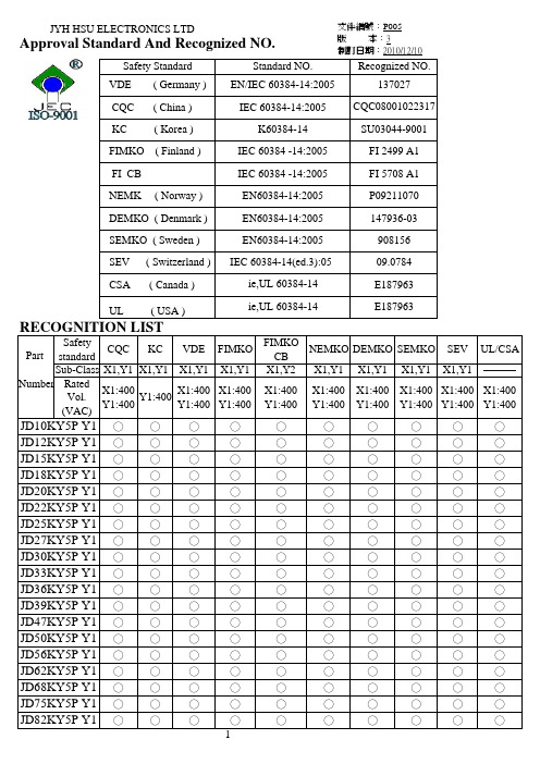
JEC Y 系列承认书(P005)
文件編號:P005
INTRODUCTION
版 本:3 制訂日期:2010/12/10
These Ceramic Disc Capacitors are specifically designed for AC applications and meet the
CQC ( China )
IEC 60384-14:2005 CQC08001022317
KC ( Korea )
K60384-14
SU03044-9001
VDE ( Germany ) EN/IEC 60384 -14:2005
137027
FIMKO ( Finland )
IEC 60384 -14:2005
X1
Y1
400 VAC
SEMKO, SEV, FIMKO,
400 VAC
400 VAC
NEMKO, DEMKO, VDE (0565 Teil 1-1)
Dielectric Rated Voltage Withstanding Voltage
Dissipation Y5P,Y5U
Test Voltage
10 pF to 4700 pF. measured at 1KHz±10%, 1.0 - 5.0 Vrms, 25℃
( C ) Tolerance
Insulation Resistance Temperature Typ) e Code
±10%
Y5P
±20%
Y5U,Y5V
( I R 10000 MΩ min, 500 VDC
(1) (2) (3) (4) (5)
(2) Rated capacitance
苯乙烯储存、储罐最低要求
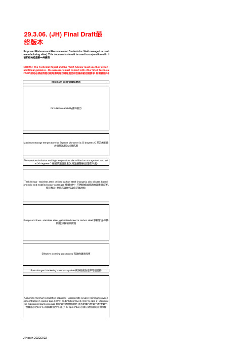
29.3.06. (JH) Final Draft 最终版本Proposed Minimum and Recommended Controls for Shell managed or contracmanufacturing sites). This documents should be used in conjunction with the relevant HSSE checklist 本清单适用于公司管理或租用的苯乙烯储罐( 不包括客户和生产现场的储罐).本清单应该和有关检查表一并使用.NOTES : The Technical Expert and the HSSE Advisor must use their expert judadditional guidance - the assessors must consult with other Shell Technical or HSSE Experts prior to making a final assessment of the facility (see attached list). 说明: 技术专家和HSSE 顾问必须应用他们的专用判定以确定是否符合最低的控制要求. 如需要额外的指导, 评估人可和壳牌公司技术和HSSE 专家进行咨询,以完成最终的评估NOTES : Recommended Controls represent additional good practice measures说明: 建议的控制措施表示为推荐的良好做法,应该考虑采纳, 并在评估时讨论concentration in vapour gap, 6-8 %) and inhibitor levels (min 10 ppm pTBC) mustbe maintained during storage 假定最小的循环能力-适当的氧气含量(气相中氧气含量最小为6-8 %) 和抑聚剂水平(最小 10 ppm Ptbc) 必须在储存期间有效保留如上述任何一个发生明显变, 测试频率应提高,并测试额外参数假定上述最低条件得到满足,关键数据和测量的频率如下ntracted Styrene Monomer Storage Tanks (this excludes customer tanks and tanks on our ownn conjunction with the relevant HSSE checklist 本清单适用于公司管理或租用的苯乙烯储罐( 不包括客户和生产现场的储罐).本清单应rt judgement to assess whether these Minimum Controls have been met. If there are areas which require other Shell Technical or HSSE Experts prior to making a final assessment of the facility (see attached list). 说明: 技术专家和控制要求. 如需要额外的指导, 评估人可和壳牌公司技术和HSSE 专家进行咨询,以完成最终的评估sures which should be considered and discussed during the assessment 说明: 建议的控制措施表示为推荐的良。
绝缘试验简介1JNL100032-384.pdf Rev. 00

Document Number No of Pages11No of Attached Pages The Three Gorges-Changzhou ± 500 kV DCTransmission Project1JNL100032-384Prepared Title Reg./Class no.Dong Wu, 1999-12-02Approved Resp Dept Hans-Ola Bjarme, 2000-02-10PTU Dielectric type test specificationWS-FE-001This document is issued by means of a computerized system. The digitally stored original is electronically approved.The approved document has a name and date entered in the approved-field. A manual signature is not required.Summary Rev ind Revision text Prepared Approved This report describes the dielectric type-test program for the testing of thevalves of the Three Gorges-Changzhou ±500 kV DC Transmission Project.The test will be performed on a double valve structure. The test programcomplies with the Requirement Specification of the thyristor valves and the IEC60700.Table of Contents1General (3)2Acceptance criteria for type test (3)3Test on valve support structure (4)3.1DC withstand and corona voltage test (4)3.2AC withstand and corona voltage test (4)3.3Switching impulse withstand voltage test (5)3.4Lightning impulse withstand voltage test (5)3.5Steep-front impulse withstand voltage test (5)4Tests on multiple valve unit (5)4.1DC withstand and corona voltage test (5)4.2Switching impulse withstand voltage test (6)4.3Lightning impulse withstand voltage test (6)4.4Steep-front impulse withstand voltage test (6)5Test on single valve (7)5.1DC withstand and corona voltage test (7)5.2Wet DC withstand voltage test (8)5.3AC withstand and corona voltage test (8)5.4Switching impulse withstand voltage test (8)5.5Wet switching impulse withstand voltage test (9)5.6Lightning impulse withstand voltage test (9)5.7Steep-front impulse withstand voltage test (9)5.8Non-periodic firing test (9)6Attachment: quotation of the Specification (10)Criteria for successful type testing applicable to thyristor levels (10)Criteria for successful type testing applicable to the valve as a whole (11)1 GeneralThe dielectric type tests will be performed according to the Requirement Specification of the thyristor valve and IEC Publication 60700 (1998).The dielectric type tests are divided into high voltage tests on:•Valve support structure including cooling pipes and light guides•Multiple Valve Unit (Double Valve)•Single valveThe tests will be common for the Longquan and Zhengping valves. The test levels meet or exceed the test requirements for the valves in both stations.The test levels stated below are valid for a 12-pulse bridge rating of U DN=500 kV, I DN=3000 A. Water at room temperature shall be circulated throughthe valve. The conductivity of the cooling water shall not be less than 0.5 µS/cm.The correction of the test voltage for atmospheric conditions shall be calculated according to IEC 60-1 (1989). When applicable, the atmospheric correction factorshall be calculated before each individual test using the actual test conditions in thetest laboratory, corresponding to a valve hall temperature of 60°C, relativehumidity of 10%, and an altitude of 154 meters.2 Acceptance criteria for type testTo check for faulty components of the valve modules at the type tests, the following checks (= Subsequent test) shall be performed after the completion of thedielectric tests.•Short circuit check•Impedance check•Firing check•Protective firing check•Recovery protection check•Reverse blocking voltage check•Short circuit check (again)•Impedance check (again)During the dielectric tests, every single thyristor level will be checked for short circuit with the thyristor test unit after each individual test. The criteria forsuccessful type test are quoted from section 5.1.13.3 and 5.1.13.4 of theSpecification and given in the attachment.3 Test on valve support structureThe cooling water pipes and light guides are included in the valve supportstructure.For all tests on valve support structure described below, the main terminals ofthe valve shall be connected together and the test voltage applied between the mainterminals and ground.3.1 DC withstand and corona voltage testThe test shall be performed with both positive and negative polarity. Themaximum operating d.c. voltage of the double valve, U dms , is calculated from thepole voltage:U dms =515/2=257.5 kVThe test voltages are:• U DC1 =1.6×U dms =1.6×257.5=412 kVDuration 1 minute• U DC2 =1.3×U dms =1.3×257.5=335 kVDuration 3 hoursThe atmospheric correction factor shall be applied to the one minute testvoltage, U DC1. If visible or audible corona occurs during the 1 min test, theinception and extinction voltages shall be recorded.During the last hour of the 3 hour test, partial discharge measurements shallbe carried out. The acceptable maximum average rates of discharge pulses are asfollows:• > 300 pCmax 15 pulses per minute • > 500 pCmax 7 pulses per minute • > 1000 pCmax 3 pulses per minute • > 2000 pC max 1 pulse per minuteIf the partial discharge criterion is not met, corrective actions shall be takenand the test repeated.3.2 AC withstand and corona voltage testFor the double valve, the maximum continuous operating voltage is the samevoltage as for the single valve. This voltage, U ms , including commutationovervoltage, is calculated as:U ms =1.129733max ××=×ππk U c dioabs =342 kV peak The test voltages are:• U AC1 = 1.3×k dov ×U ms /√2=1.3×1.3×342/√2=409 kV rmsDuration1 minute • U AC2 = 1.15×U ms /√2=278 kV rmsDuration30 minThe atmospheric correction factor shall be applied to the one minute test voltage, U AC1.During the 30 min test, the level of partial discharge shall be monitored and recorded. If the value of partial discharge is below 200 pC, the design shall beaccepted. If the value of partial discharge exceeds 200 pC, the test result shall beevaluated in accordance with recommendations in IEC 60700, section B.3.3 Switching impulse withstand voltage testThe arrester protective level for a double valve is 639 kV.Test voltage: 1.20×639=767 kV.Wave shape:200-300/2000-3000 µs.5 impulses of each polarity. The atmospheric correction factor shall be applied.3.4 Lightning impulse withstand voltage testThe arrester protective level for a double valve is 630 kV.Test voltage: 1.25 × 630=788 kV.Wave shape: 1.2/50 µs.5 impulses of each polarity. The atmospheric correction factor shall be applied.3.5 Steep-front impulse withstand voltage testThe arrester protective level for a double valve is 675 kV.Test voltage: 1.25×675=844 kV.5 impulses of each polarity. The atmospheric correction factor shall be applied.4 Tests on multiple valve unitThe tests on the multiple valve unit will be performed on a double valve. For these tests, the valves shall be in cold condition.When testing the double valve, the impedance equivalent to that of one single valve shall be connected between the low voltage terminal of the double valve andearth. The test voltages shall be applied between the high voltage terminal andearth. With this arrangement, the test voltages shall be the same as for testing aquadruple valve.Grounded shields shall be suitably arranged around the valve structure to simulate effects of nearby building steel, grounding rods and other structure whichinfluences the stray capacitance to ground.4.1 DC withstand and corona voltage testThe test shall be performed with both positive and negative polarity. The ratedd.c. voltage is 500 kV.The test voltages are:•U dc1 = 1.6×500=800 kVDuration: 1 min•U dc2 = 1.3×500=650 kVDuration: 3 hoursThe atmospheric correction factor shall be applied to the one minute test voltage, U DC1.During the last hour of the 3 hour test, partial discharge measurements shall be carried out. The acceptable maximum average rates of discharge pulses over themeasuring period are as follows:•> 300 pC max 15 pulses per minute•> 500 pC max 7 pulses per minute•> 1000 pC max 3 pulses per minute•> 2000 pC max 1 pulse per minuteIf the partial discharge criterion is not met, corrective actions shall be taken and the test repeated.4.2 Switching impulse withstand voltage testThe arrester protective level for the high-voltage terminal is 1136 kV.Test voltage: 1.20 × 1136=1364 kV.Wave shape:200-300/2000-3000 µs.5 impulses of each polarity. The atmospheric correction factor shall be applied.4.3 Lightning impulse withstand voltage testThe arrester protective level for the high-voltage terminal is 1122 kV.Test voltage: 1.25 × 1122=1403 kV.Wave shape: 1.2/50 µs.5 impulses of each polarity. The atmospheric correction factor shall be applied.4.4 Steep-front impulse withstand voltage testThe arrester protective level for the high-voltage terminal is 1234 kV.Test voltage: 1.25 × 1234=1543 kV.Wave shape:1200 kV/µsec.5 impulses of each polarity. The atmospheric correction factor shall be applied.5 Test on single valveThe single valve tests will be performed on the Longquan valve, i.e 15 thyristor modules. The voltage stress per thyristor level is however slightly higherin the Zhengping valves than in the Longquan valves. Therefore test voltages areadjusted with a factor to give the maximum stresses during the test. This factor isequal to 1.02 for the impulse tests and the one minute AC test. This factor is equalto 1.074 for the thirty minutes AC test and the DC test. The atmospheric correctionfactor shall not be applied to the test voltages.The single valve assembly, with the surge arrester support structure mounted and the redundant thyristor levels short circuited (if not otherwise specified) shallbe subjected to the tests.The tests will be performed with water of room temperature circulating through the valve. The conductivity of the cooling water shall be approximately0.5µS/cm, the maximum conductivity which would initiate a high conductivityalarm.Where tests on a hot valve is specified, the hot valve condition shall be achieved by a continuous direct current and cooling water. The valve is heated untilthe thyristor junction reaches a temperature corresponding to the highest possibleduring operation.During the valve withstand voltage tests 5.4, 5.6 and 5.7,at a voltage level of 50% or more of the full magnitude of the test voltages, voltage measurementsacross the thyristors shall be made at four intermediate points along the valve, to bedetermined by the Owner.The Thyristor Control Units are precharged using a 30 kV switching or AC voltage for the impulse withstand voltage tests.5.1 DC withstand and corona voltage testThe test shall be performed with both positive and negative polarity. The rated direct voltage for a 6-pulse bridge is 250 kV.The test voltages are:•U DC1 = 1.6 × 250 × 1.074=430 kVDuration: 1 min•U DC2 = 0.8 × 250 × 1.074=215 kVDuration: 3 hoursStarting from a level lower than 50% of U DC1 the test voltage is increased to U DC1 and kept there for 1 min. After that the voltage is reduced to U DC2 and keptthere for 3 hours. During the 3 hour test internal discharge measurements will becarried out. The acceptable maximum average rate of discharge pulses over themeasuring period are as follows:> 300 pC max 15 pulses per minute> 500 pC max 7 pulses per minute> 1000 pC max 3 pulses per minute> 2000 pC max 1 pulses per minuteIf the partial discharge criterion is not met, corrective actions shall be taken and the test repeated.5.2 Wet DC withstand voltage testThe DC withstand voltage test will be repeated on a valve with a coolingliquid leak on one of the top modules of the valve stack. The rate of leakage shallbe 15 liters per hour.The test voltages are the same as in sec. 5.1, i.e:• U DC1 = 430 kVDuration1 min.• U DC2 = 215 kVDuration 5 min.5.3 AC withstand and corona voltage testThe test shall be performed with symmetrical voltage.The test voltage, U AC1, is calculated from the highest no-load phase-to-phasevoltage on the valve side of the transformer, U vmax .U vmax =2972323max ×=ππU dioabs =220 kV rms U AC1 = U vmax ×k dov ×k c ×1.15×1.02=220×1.3×1.1×1.15×1.02U AC1 = 369 kV rmsDuration: 1 min.The test voltage, U AC2, is calculated from the maximum value of steady-statevoltage, U p , in the forward direction (inverter operation) including commutationovershoot.U p =15.128333max ××=×ππk U c dioabs =341 kV peak U AC2 = U p 21× 1.15 × 1.074=2341× 1.15 × 1.074U AC2 = 298 kV rmsDuration:30 min.During the 30 min test, the level of partial discharge shall be monitored andrecorded. If the value of partial discharge is below 200 pC, the design shall beaccepted. If the value of partial discharge exceeds 200 pC, the test result shall beevaluated in accordance with recommendations in IEC 60700, section B.5.4 Switching impulse withstand voltage testThe tests will be performed with Thyristor Control Units (TCU) energized.The arrester protective level for a single valve is 497 kVTest voltage:1.15×497×1.02= 583 kV Wave shape:200-300/2000-3000 µs5 impulses of each polarityIf protective firing occurs the test will be repeated at a voltage level below protective firing.5.5 Wet switching impulse withstand voltage testThe switching impulse withstand voltage test will be repeated on a valve witha cooling liquid leak on one of the top modules of the valve stack. The rate ofleakage shall be 15 liters per hour.The test voltage and wave shape are the same as in sec.5.4 and the test shall be performed with 5 impulses of each polarityIf protective firing occurs the test will be repeated at a voltage level below protective firing.5.6 Lightning impulse withstand voltage testThe test shall be performed with the Thyristor Control Units (TCU) energized and the valve at maximum service temperature.The arrester protective level for a single valve is 492 kV.Test voltage: 1.15×492×1.02=577 kVWave shape: 1.2/50 µs5 impulses of each polarity.If protective firing occurs the test shall be repeated at a voltage level below protective firing.5.7 Steep-front impulse withstand voltage testThe test shall be performed with the Thyristor Control Units (TCU) energized and the valve at maximum service temperature.The arrester protective level for a single valve is 559 kV.Test voltage: 1.20×559×1.02=684 kVWave shape: 1200 kV/µs5 impulses of each polarityIf protective firing occurs the test shall be repeated at a voltage level below protective firing.5.8 Non-periodic firing testThe tests shall be performed using the Parallel Capacitor Method, with the Thyristor Control Units (TCU) energized. The redundant thyristors shall not beshort-circuited during the test.The test will be performed with 5 impulses of positive polarity.The valve shall be fired at a level below the protective firing level, i.e. appr.switching impulse voltage as determined during the impulse withstand tests. If theprotective firing did not occur during the switching impulse test, the valve will befired at 583 kV as per clause 5.4.The valve firing current shall simulate the maximum valve firing current stress which can occur at a protective firing of the valve.6 Attachment: quotation of the SpecificationThe following text are quoted directly from the Contract.Criteria for successful type testing applicable to thyristor levels1)If, following a type test as listed in clause 5.1.13.5, more than one thyristorlevel (alternatively more than 1% of the series-connected thyristor levels in acomplete valve, if greater) has become short circuited, then the valve shall bedeemed to have failed the type tests.2)If, following a type test, one thyristor level (or more if still within the 1%limit) has become short circuited, then the failed level(s) shall be restored andthe type test repeated.3)If, on retest, further short circuits occur within the permitted limit then, if afailure has occurred in the same location as previously, the valve shall bedeemed to have failed the type tests. If a failure occurs in a different location,then the failed level(s) shall be restored and the test repeated.4)If the cumulative number of short circuited thyristor levels during all typetests is more than 3% of the series-connected thyristor levels in a completevalve, then the valve shall be deemed to have failed the type test.5)When type tests are performed on valve sections, the criteria for acceptanceabove also apply since the number of valve sections tested shall not be lessthan the number of sections in a complete valve.6)The valve or valve sections shall be checked after each type test to determinewhether or not any thyristor levels have become short circuited. Failedthyristors or auxiliary components found during or at the end of a type testmay be replaced before further testing.7)At the completion of the test programme, the valve or valve sections shallundergo a series of check tests.8)Thyristor level short circuits occurring during the check tests shall be countedas part of the criteria for acceptance defined above. In addition to shortcircuited levels, the total number of thyristor levels exhibiting faults which donot result in thyristor level short circuit, which are discovered during the typetest programme and the subsequent check tests, shall not exceed 3% of theseries-connected thyristor levels in a complete valve.9)When applying the percentage criteria to determine the permitted maximumnumber of short circuited thyristor levels and the permitted maximum numberof levels with faults which have not resulted in thyristor level becoming shortcircuited, the rounding off of all fractions should be determined by thenegotiation between the Owner and the Contractor.The distribution of short circuited levels and of other thyristor level faults at theend of all type tests shall be essentially random and not show any pattern that maybe indicative of inadequate design.ABB Power Systems Report Dielectric type test specification1JNL100032-384We reserve all rights in this document and in the information contained herein. Reproduction, use or disclosure to third parties without express authority is strictly forbidden. ABB Power Systems (SE)- 11 -Criteria for successful type testing applicable to the valve as a wholeNo external flashover of a valve nor breakdown of the cooling system within thevalve, nor disruptive discharge in dielectric material forming part of the firingpulse transmission and distribution system shall be permitted.。
DATASHEET (TP4054 线性锂离子电池充电器)

间,并应通过至少一个 1μF 电容器进行旁 路。当 VCC 降至 BAT 引脚电压的 30mV 以 内,TP4054 进入停机模式,从而使 IBAT 降至 2μA 以下。 PROG(引脚 5) :充电电流设定、充电电流 监控和停机引脚。 在该引脚与地之间连接一 个精度为 1%的电阻器 RPROG 可以设定充电 电流。当在恒定电流模式下进行充电时,引 脚的电压被维持在 1V。 PROG 引脚还可用来关断充电器。将设定电 阻器与地断接,内部一个 2.5μA 电流将 PROG 引脚拉至高电平。当该引脚的电压达 到 2.70V 的停机门限电压时, 充电器进入停 机模式,充电停止且输入电源电流降至 45μA。重新将 RPROG 与地相连将使充电器 恢复正常操作状态。
TEL:0755-82863877 13242913995 FAX:0755-82863778 E-MAIL:panxia168@
DATASHEET
(TP4054 线性锂离子电池充电器)
1
TP4054 线性锂离子电池充电器
描述
TP4054 是一款完整的单节锂离子电池采用恒定电流/恒定电压线性充电器。其 SOT 封装与较少的外部元件数目使得 TP4054 成为便携式应用的理想选择。 TP4054 可以适合 USB 电源和适配器电源工作。 由于采用了内部 PMOSFET 架构,加上防倒充电路,所以不需要外部检测电阻器和 隔离二极管。热反馈可对充电电流进行调节,以便在大功率操作或高环境温度条件下对 芯片温度加以限制。 充电电压固定于 4.2V, 而充电电流可通过一个电阻器进行外部设置。 当充电电流在达到最终浮充电压之后降至设定值 1/10 时, TP4054 将自动终止充电循环。 当输入电压(交流适配器或 USB 电源)被拿掉时,TP4054 自动进入一个低电流状 态,将电池漏电流降至 2uA 以下。也可将 TP4054 置于停机模式,以而将供电电流降至 45uA。TP4054 的其他特点包括充电电流监控器、欠压闭锁、自动再充电和一个用于指 示充电结束和输入电压接入的状态引脚。
Perkadox 14-40B-PD-S 产品数据表说明书
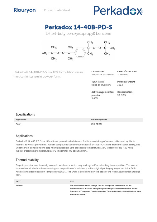
Product Data SheetPerkadox 14-40B-PD-S Di(tert-butylperoxyisopropyl) benzenePerkadox® 14-40B-PD-S is a 40% formulation on an inert carrier system in powder form.CAS number2212-81-9, 25155-25-3EINECS/ELINCS No.218-664-7TSCA statuslisted on inventoryMolecular weight338.5Active oxygen contentperoxide9.45%Concentration3.7-3.9%SpecificationsAppearance Off-white powderAssay39.0-41.0 %ApplicationsPerkadox® 14-40B-PD-S is a bifunctional peroxide which is used for the crosslinking of natural rubber and synthetic rubbers, as well as polyolefins. Rubber compounds containing Perkadox® 14-40B-PD-S have excellent scorch safety, and under certain conditions one step mixing is possible. Safe processing temperature: 135°C (rheometer ts2 > 20 min.). Typical crosslinking temperature: 175°C (rheometer t90 about 12 min.).Thermal stabilityOrganic peroxides are thermally unstable substances, which may undergo self-accelerating decomposition. The lowest temperature at which self-accelerating decomposition of a substance in the original packaging may occur is the Self-Accelerating Decomposition Temperature (SADT). The SADT is determined on the basis of the Heat Accumulation Storage Test.SADT80°CMethod The Heat Accumulation Storage Test is a recognized test method for thedetermination of the SADT of organic peroxides (see Recommendations on theTransport of Dangerous Goods, Manual of Tests and Criteria - United Nations, NewYork and Geneva).StorageDue to the relatively unstable nature of organic peroxides a loss of quality can be detected over a period of time. To minimize the loss of quality, Nouryon recommends a maximum storage temperature (Ts max.) for each organic peroxide product.Ts max.30°CNote When stored under strictly recommended storage conditions, Perkadox® 14-40B-PD-S will remain within the Nouryon specifications for a period of at least 12months after delivery.Packaging and transportThe standard packaging is a cardboard box for 25 kg peroxide formulation. Both packaging and transport meet the international regulations. For the availability of other packed quantities consult your Nouryon representative. Perkadox®14-40B-PD-S is classified as Flammable solid, class 4. 1, UN 1325.Safety and handlingKeep containers tightly closed. Store and handle Perkadox® 14-40B-PD-S in a dry well-ventilated place away from sources of heat or ignition and direct sunlight. Never weigh out in the storage room. Avoid contact with reducing agents (e. g. amines), acids, alkalines and heavy metal compounds (e. g. accelerators, driers and metal soaps). Please refer to the Safety Data Sheet (SDS) for further information on the safe storage, use and handling of Perkadox® 14-40B-PD-S. This information should be thoroughly reviewed prior to acceptance of this product. The SDS is available at /sds-search.Major decomposition productsMethane, Acetone, tert-Butanol, Di(2-hydroxyisopropyl)benzene, Diacetylbenzene, Acetyl 2-hydroxyisopropyl benzeneAll information concerning this product and/or suggestions for handling and use contained herein are offered in good faith and are believed to be reliable.Nouryon, however, makes no warranty as to accuracy and/or sufficiency of such information and/or suggestions, as to the product's merchantability or fitness for any particular purpose, or that any suggested use will not infringe any patent. Nouryon does not accept any liability whatsoever arising out of the use of or reliance on this information, or out of the use or the performance of the product. Nothing contained herein shall be construed as granting or extending any license under any patent. Customer must determine for himself, by preliminary tests or otherwise, the suitability of this product for his purposes.The information contained herein supersedes all previously issued information on the subject matter covered. The customer may forward, distribute, and/or photocopy this document only if unaltered and complete, including all of its headers and footers, and should refrain from any unauthorized use. Don’t copythis document to a website.Perkadox® is a registered trademark of Nouryon Functional Chemicals B. V. or affiliates in one or more territories.Contact UsPolymer Specialties Americas************************Polymer Specialties Europe, Middle East, India and Africa*************************Polymer Specialties Asia Pacific************************2022-12-5© 2022Polymer crosslinking Perkadox 14-40B-PD-S。
NI 9219 四通道多功能测试模块说明书

DAT ASHEETNI 92194 AI, 100 S/s/ch Simultaneous, Universal Measurements•Spring-terminal connectivity•Support for Thermocouple (50 S/s/ch), RTD, Resistance,Full-Bridge, Half-Bridge, Quarter-Bridge, V oltage, and Current Measurements•V oltage and current excitation•250 V AC, CAT II, channel-to-channel isolationThe NI 9219 is a universal C Series module designed for multipurpose testing in any NI CompactDAQ or CompactRIO chassis. With the NI 9219, you can measure several signals from sensors such as strain gages, RTDs, thermocouples, load cells, and other poweredsensors. The channels are individually selectable, so you can perform a different measurement type on each of the four channels. Measurement ranges differ for each type of measurement and include up to ±60 V for voltage and ±25 mA for current.Kit ContentsAccessories • NI 9219• NI 9219 Getting Started Guide • Spring-Terminal Tool• NI 9972 Backshell Connector KitNI C Series OverviewNI provides more than 100 C Series modules for measurement, control, and communication applications. C Series modules can connect to any sensor or bus and allow for high-accuracy measurements that meet the demands of advanced data acquisition and control applications.•Measurement-specific signal conditioning that connects to an array of sensors and signals •Isolation options such as bank-to-bank, channel-to-channel, and channel-to-earth ground •-40 °C to 70 °C temperature range to meet a variety of application and environmental needs•Hot-swappableThe majority of C Series modules are supported in both CompactRIO and CompactDAQ platforms and you can move modules from one platform to the other with no modification. CompactRIOCompactRIO combines an open-embedded architecturewith small size, extreme ruggedness, and C Seriesmodules in a platform powered by the NI LabVIEWreconfigurable I/O (RIO) architecture. Each systemcontains an FPGA for custom timing, triggering, andprocessing with a wide array of available modular I/O tomeet any embedded application requirement. CompactDAQCompactDAQ is a portable, rugged data acquisition platformthat integrates connectivity, data acquisition, and signalconditioning into modular I/O for directly interfacing to anysensor or signal. Using CompactDAQ with LabVIEW, youcan easily customize how you acquire, analyze, visualize, andmanage your measurement data.2| | NI 9219 DatasheetSoftwareLabVIEW Professional Development System for Windows•Use advanced software tools for large project development•Generate code automatically using DAQ Assistant and InstrumentI/O Assistant•Use advanced measurement analysis and digital signal processing•Take advantage of open connectivity with DLLs, ActiveX, and .NETobjects•Build DLLs, executables, and MSI installersNI LabVIEW FPGA Module•Design FPGA applications for NI RIO hardware•Program with the same graphical environment used for desktop andreal-time applications•Execute control algorithms with loop rates up to 300 MHz•Implement custom timing and triggering logic, digital protocols, andDSP algorithms•Incorporate existing HDL code and third-party IP including Xilinx IPgenerator functions•Purchase as part of the LabVIEW Embedded Control and MonitoringSuiteNI LabVIEW Real-Time Module•Design deterministic real-time applications with LabVIEWgraphical programming•Download to dedicated NI or third-party hardware for reliableexecution and a wide selection of I/O•Take advantage of built-in PID control, signal processing, andanalysis functions•Automatically take advantage of multicore CPUs or setprocessor affinity manually•Take advantage of real-time OS, development and debuggingsupport, and board support•Purchase individually or as part of a LabVIEW suiteNI 9219 Datasheet| © National Instruments| 3NI 9219 CircuitryCH0CH3•The NI 9219 is channel-to-channel isolated.•Four 24-bit analog-to-digital converters (ADCs) simultaneously sample all four analog input channels.•The NI 9219 enables an excitation circuit for all input modes that require excitation.•The NI 9219 reconfigures the signal conditioning for each measurement type.Voltage Circuitry•The ADC measures voltage across the HI and LO terminals.•The NI 9219 has ±60 V, ±15 V, ±4 V, ±1 V, and ±125 mV voltage ranges.Current Circuitry4 | | NI 9219 DatasheetThe NI 9219 computes current from the voltage that the ADC measures across an internal shunt resistor.Thermocouple Circuitry•The NI 9219 uses the ±125 mV range of the ADC to return a voltage reading.•Each channel has a built-in thermistor for cold-junction compensation (CJC) calculations. 4-Wire Resistance and 4-Wire RTD CircuitryRTD/•The NI 9219 sources a current, which varies based on the resistance of the load, between the EX+ and EX- terminals. The NI 9219 computes measured resistance from theresulting voltage reading.•Lead wire resistance does not affect these measurement types because a negligible amount of current flows across the HI and LO terminals due to the high input impedance of the ADC.3-Wire RTD CircuitryRTDNI 9219 Datasheet| © National Instruments| 5•The NI 9219 sources a current, which varies based on the resistance of the load, between the EX+ and EX- terminals.•The NI 9219 compensates for lead wire resistance in hardware if all the lead wires have the same resistance.•The NI 9219 applies a gain of 2x to the voltage across the negative lead wire and the ADC uses this voltage as the negative reference to cancel the resistance error across the positive lead wire.2-Wire Resistance and Quarter-Bridge Circuitry•The NI 9219 sources a current, which varies based on the resistance of the load, between the HI and LO terminals.•The NI 9219 computes measured resistance from the resulting voltage reading.•2-Wire Resistance and Quarter-Bridge measurement types do not compensate for lead wire resistance.Full-Bridge Circuitry•The ADC reads the HI and LO inputs differentially.•The internal voltage excitation sets the input range of the ADC and returns voltage readings that are proportional to the excitation level. The internal excitation voltagevaries based on the resistance of the sensor.6| | NI 9219 DatasheetHalf-Bridge Circuitry•The HI input is referenced to EX-.•The internal voltage excitation sets the input range of the ADC and returns voltage readings that are proportional to the excitation level. The internal excitation voltagevaries based on the resistance of the sensor.Digital In Circuitry•The NI 9219 has a 60 V unipolar threshold that you can set in software.•The digital in measurement type is only supported in CompactRIO systems.Open Contact Circuitry•The NI 9219 sources a current between the HI and LO terminals and determines if the two terminals are open or closed based on the measured current through the terminals.•When the circuit is open, make sure no more than ±60 V is sourced across the switch.•The open contact measurement type is only supported in CompactRIO systems.NI 9219 Datasheet| © National Instruments| 7Timing ModesThe NI 9219 supports high-resolution, best 50 Hz rejection, best 60 Hz rejection, and high-speed timing modes. High-resolution timing mode optimizes maximum overall noise rejection and provides rejection of 50 Hz and 60 Hz noise . Best 50 Hz rejection optimizes 50 Hz noise rejection. Best 60 Hz rejection optimizes 60 Hz noise rejection. High-speed timing mode optimizes sample rate.NI 9219 SpecificationsThe following specifications are typical for the range -40 °C to 70 °C unless otherwise noted.Caution Do not operate the NI 9219 in a manner not specified in this document.Product misuse can result in a hazard. You can compromise the safety protectionbuilt into the product if the product is damaged in any way. If the product isdamaged, return it to NI for repair.Input CharacteristicsNumber of channels 4 analog input channelsADC resolution24 bitsType of ADC Delta-sigma (with analog prefiltering) Sampling mode SimultaneousType of TEDS supported IEEE 1451.4 TEDS Class 2 (Interface)8| | NI 9219 DatasheetTable 1. Input Ranges (Continued)Conversion time, all channelsNo channels configured as a thermocoupleHigh speed10 msBest 60 Hz rejection110 msBest 50 Hz rejection130 msHigh resolution500 msOne or more channels configured as a thermocoupleHigh speed20 msBest 60 Hz rejection120 msBest 50 Hz rejection140 msHigh resolution510 msOvervoltage protectionTerminals 1 and 2±30 V±60 VTerminals 3 through 6, across anycombinationInput impedanceV oltage and Digital In (±60 V, ±15 V,1 MΩ±4 V)Current< 40 ΩAll other measurement types>1 GΩNI 9219 Datasheet| © National Instruments| 9Table 2. Accuracy±1 °C typicalCold-junction compensation sensoraccuracy12-wire resistance accuracy assumes 0 Ω of lead wire resistance. 2-wire resistance accuracy depends on the lead wire resistance.10| | NI 9219 DatasheetTable 3. StabilityNI 9219 Datasheet| © National Instruments| 11Table 4. Input Noise in ppm of Range (Continued)Input bias current<1 nAINL±15 ppmCMRR (ƒin = 60 Hz)>100 dBNMRRBest 60 Hz rejection90 dB at 60 HzBest 50 Hz rejection80 dB at 50 HzHigh resolution65 dB at 50 Hz and 60 Hz2Excitation level is a characteristic and is not software-selectable.12| | NI 9219 DatasheetTable 5. Half-Bridge, Full-Bridge, Quarter-Bridge, Resistance, and RTD Excitation Level(Continued)MTBF384,716 hours at 25 °C; Bellcore Issue 2,Method 1, Case 3, Limited Part Stress Method Power RequirementsPower consumption from chassisActive mode750 mW maximumSleep mode25 µW maximumThermal dissipation (at 70 °C)Active mode625 mW maximumSleep mode25 µW maximumPhysical CharacteristicsIf you need to clean the module, wipe it with a dry towel.Tip For two-dimensional drawings and three-dimensional models of the C Seriesmodule and connectors, visit /dimensions and search by module number.Spring-terminal wiringGauge0.08 mm2 to 1.0 mm2 (28 AWG to 18 AWG)copper conductor wireWire strip length7 mm (0.28 in.) of insulation stripped from theend2Excitation level is a characteristic and is not software-selectable.NI 9219 Datasheet| © National Instruments| 13Temperature rating90 °C minimumWires per spring terminal One wire per spring terminalConnector securementSecurement type Screw flanges providedTorque for screw flanges0.2 N · m (1.80 lb · in.)Weight156 g (5.5 oz)Safety VoltagesConnect only voltages that are within the following limits.Channel-to-channelContinuous250 V AC, Measurement Category IIWithstand1,390 V AC, verified by a 5 s dielectricwithstand testChannel-to-earth groundContinuous250 V AC, Measurement Category IIWithstand2,300 V AC, verified by a 5 s dielectricwithstand testZone 2 hazardous locations applications in Europe60 VDC, Measurement Category IChannel-to-channel and channel-to-earth groundMeasurement Category I is for measurements performed on circuits not directly connected to the electrical distribution system referred to as MAINS voltage. MAINS is a hazardous live electrical supply system that powers equipment. This category is for measurements of voltages from specially protected secondary circuits. Such voltage measurements include signal levels, special equipment, limited-energy parts of equipment, circuits powered by regulated low-voltage sources, and electronics.Caution If using in Division 2 or Zone 2 hazardous locations applications, do notconnect the NI 9219 to signals or use for measurements within MeasurementCategories II, III, or IV.Note Measurement Categories CAT I and CAT O are equivalent. These test andmeasurement circuits are not intended for direct connection to the MAINS buildinginstallations of Measurement Categories CAT II, CAT III, or CAT IV. Measurement Category II is for measurements performed on circuits directly connected to the electrical distribution system. This category refers to local-level electrical distribution, such as that provided by a standard wall outlet, for example, 115 V for U.S. or 230 V for Europe.14| | NI 9219 DatasheetCaution Do not connect the NI 9219 to signals or use for measurements withinMeasurement Categories III or IV.Hazardous LocationsU.S. (UL)Class I, Division 2, Groups A, B, C, D, T4;Class I, Zone 2, AEx nA IIC T4Canada (C-UL)Class I, Division 2, Groups A, B, C, D, T4;Class I, Zone 2, Ex nA IIC T4Europe (ATEX) and International (IECEx)Ex nA IIC T4 GcSafety and Hazardous Locations StandardsThis product is designed to meet the requirements of the following electrical equipment safety standards for measurement, control, and laboratory use:•IEC 61010-1, EN 61010-1•UL 61010-1, CSA 61010-1•EN 60079-0:2012, EN 60079-15:2010•IEC 60079-0: Ed 6, IEC 60079-15; Ed 4•UL 60079-0; Ed 5, UL 60079-15; Ed 3•CSA 60079-0:2011, CSA 60079-15:2012Note For UL and other safety certifications, refer to the product label or the OnlineProduct Certification section.Electromagnetic CompatibilityThis product meets the requirements of the following EMC standards for sensitive electrical equipment for measurement, control, and laboratory use:•EN 61326 (IEC 61326): Class A emissions; Industrial immunity•EN 55011 (CISPR 11): Group 1, Class A emissions•AS/NZS CISPR 11: Group 1, Class A emissions•FCC 47 CFR Part 15B: Class A emissions•ICES-001: Class A emissionsNote For the standards applied to assess the EMC of this product, refer to theOnline Product Certification section.CE ComplianceThis product meets the essential requirements of applicable European Directives, as follows:•2014/35/EU; Low-V oltage Directive (safety)•2014/30/EU; Electromagnetic Compatibility Directive (EMC)•94/9/EC; Potentially Explosive Atmospheres (ATEX)NI 9219 Datasheet| © National Instruments| 15Online Product CertificationRefer to the product Declaration of Conformity (DoC) for additional regulatory compliance information. To obtain product certifications and the DoC for this product, visit / certification, search by model number or product line, and click the appropriate link in the Certification column.Shock and VibrationTo meet these specifications, you must panel mount the system.Operating vibrationRandom (IEC 60068-2-64) 5 g rms, 10 Hz to 500 HzSinusoidal (IEC 60068-2-6) 5 g, 10 Hz to 500 HzOperating shock (IEC 60068-2-27)30 g, 11 ms half sine; 50 g, 3 ms half sine;18 shocks at 6 orientations EnvironmentalRefer to the manual for the chassis you are using for more information about meeting these specifications.-40 °C to 70 °COperating temperature(IEC 60068-2-1, IEC 60068-2-2)-40 °C to 85 °CStorage temperature(IEC 60068-2-1, IEC 60068-2-2)Ingress protection IP40Operating humidity (IEC 60068-2-78)10% RH to 90% RH, noncondensing Storage humidity (IEC 60068-2-78)5% RH to 95% RH, noncondensing Pollution Degree2Maximum altitude2,000 mIndoor use only.Environmental ManagementNI is committed to designing and manufacturing products in an environmentally responsible manner. NI recognizes that eliminating certain hazardous substances from our products is beneficial to the environment and to NI customers.For additional environmental information, refer to the Minimize Our Environmental Impact web page at /environment. This page contains the environmental regulations and directives with which NI complies, as well as other environmental information not included in this document.16| | NI 9219 DatasheetWaste Electrical and Electronic Equipment (WEEE) EU Customers At the end of the product life cycle, all NI products must bedisposed of according to local laws and regulations. For more information abouthow to recycle NI products in your region, visit /environment/weee.电子信息产品污染控制管理办法(中国RoHS)中国客户National Instruments符合中国电子信息产品中限制使用某些有害物质指令(RoHS)。
基于超高效液相色谱-串联质谱法的纺织品中7种尼泊金酯类防腐剂测定
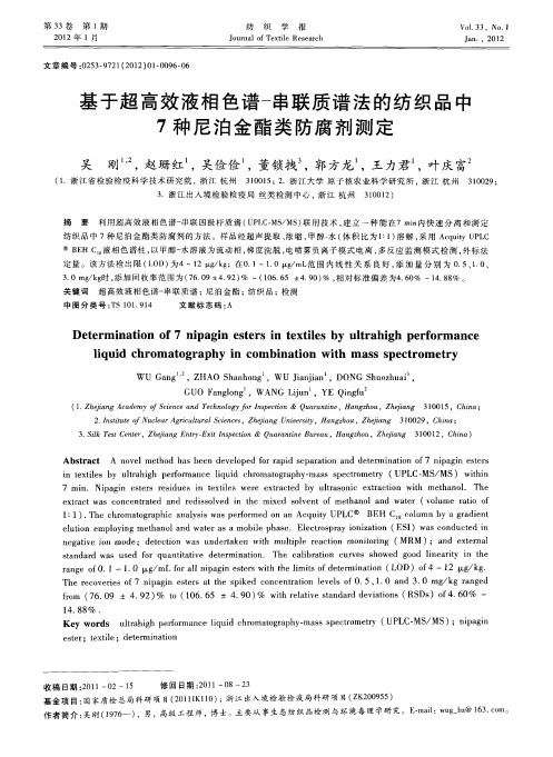
WU Ga g ,Z n HAO S a h n h n o g ,wU Ja j n ,D ini ONG S u z u i, a h oh a GUO F n ln a go g ,WAN u G n ,YE Qigu n f
( . hj n c d m c n e n eh o g f r np c o 1 Z e a gA a e yo i c a d T cn l y o Iset n& Q aa t e H n z o , hj n 3 0 1 , hn ; i fS e o i urn n , aghu Z eag 10 5 C i i i a 2 Is t e ul r g i l rl c n e , h i g U i r t , a gh u Z e a g 3 0 2 ,C ia . ntu N c a r ut a S i cs Z e a n e i H n zo , h in 0 9 h ; ito f e A c u e jn v s5 j 1 n 3 S k Ts C ne , hj n nr E iI s c o . i e e t Z ea gE t — xt n et n& Q aa t e ue u H n z o , h i g 3 , hn ) l t r i y p i u r ni ra , a gh u Z e a 0 C ia nB jn 1 1 0 2
i e te y ut hg efr n e l ud c rmao rp y mas s e t mer ( L MS MS) w ti n txi sb l a ih p r ma c i i h o tga h — s p cr t l r o q o y UP C— / i n h
尼科莱特 I S10 FTIR 光谱仪 用户手册说明书

Complete infrared spectroscopy system for routine analytical needsThermo Scientific Nicolet iS10 FTIR SpectrometerLubricants Pharmaceuticals Rubbers/PolymersChemicalsTextiles LoadEnsureIdentifyComply MeasureVerifyYour process, our answer23PackagingBiofuels/Fuels Inks/Pigments/PaintsCement CosmeticsOwning a Thermo Scientific ™ Nicolet ™ iS10 FTIR spectrometer means you are up and ready as soon as your instrument is turned on. You do not need to be a spectroscopy expert to get good data from your Nicolet iS10 spectrometer— the expertise is already built into the instrument.Materials identificationChallenges walk through your lab door every day. Handling last-minute demands from manufacturing,quality control and product development—troubleshooting is your daily “routine.” Your answers determine not only your customers’ satisfaction, but also your company’s image and profitability. Performance, ease-of-use and reliability are of paramount importance. The Nicolet iS10 spectrometer goes the distance with you—risk free.Materials verificationValidation, data integrity and push-button operation are important requirements, but no longer sufficient in today’s fast-paced, continuous-improvement business environment. Your job requires you to manage cost of ownership of your equipment, enhance productivity, save time, and ensure that human errors are at a minimum. Youdemand unambiguous answers. The Nicolet iS10 FTIR spectrometer, with award-winning Thermo Scientific ™ OMNIC ™ software, creates the most effective tool to achieve your objectives without compromise.These are only a few of the materials that can be monitored for consistent quality using the Nicolet iS10 FTIR spectrometer .Sample information loading andpreparation• M inimize user interaction by loading sample information through bar codes• S tandardize sample preparation and quality of results by using the Thermo Scientific ™ Smart iTX ™ ATR sampling accessory• A utomate method selection for error-free operationSystem is always qualified• S ave valuable time and optimize laboratory throughput by running system qualification overnight, every night with System Performance Verification (SPV)• Qualify the spectrometer and the accessory • S ystem suitability testing complements performance verification• C onstant system monitoringRunning the Nicolet iS10 FTIRspectrometer means no typing sample numbers, no printing SOPs and nomanual selection of methods. You don’t even need to touch the computer.What you get is:• Speed • Consistency • Security • Confidence4QC analysis—answers out Sample verification• V erify raw materials, intermediates and finished productsfor consistency, purity and concentration• B e absolutely confident in your pass/fail results,regardless of your sample, thanks to the new and uniquecompare tools in the Thermo Scientific™ QCheck™ feature• Q uantify your compounds with classic and chemometrictools in Thermo Scientific™ TQ Analyst™ software Comprehensive reports, quick and easy• S ystem validation status and date• Sampling accessory validation status and date• M ethod verification (suitability) status and date• S ample verification status (pass or fail)• User ID and digital signature (where applicable)• G enerated and digitally stored for convenient reviewthroughout your organizationClear and simple answers for smoothquality control and assurance.Universal sampling—realityAttenuated Total Reflectance (ATR) is a powerful sampling technique that virtually eliminates sample preparation. The Thermo Scientific Smart iTX ATR sampling accessory for the Nicolet iS10 spectrometer offers outstanding performance and universal sampling.• Multiple crystal options make it possible to sample virtually any liquid or solid • Automatic recognition, collection parameters, spectral quality check • Factory-calibrated pressure tower ensures spectral uniformity • Easy to clean and quickly load your next sample• Maximum durability; withstand hard and harsh samples with diamond ATR • OMNIC ATR correction allows spectral search without dedicated ATR libraries • Q ualification available for diamond crystalsMore than 60% of FTIR users get their resultsby using a single reflection ATR. The popular Smart iTX sampling accessory deliversexceptional energy throughput, which allows you to acquire high-quality spectra in seconds. The interchangeable crystals meet your needs for flexibility, ease of cleaning and reproducibility of data.characterized with the Smart iTX universal sampling module by using the germanium crystal.Smart iTX Universal ATR Sampling accessory reference chartCRYSTAL TYPEMATERIAL TO BE SAMPLEDDiamondZnSeGermaniumSoft solids, powders Best Best Good Rigid samples Best Weak Weak Harsh chemicals Best Weak Good Coatings on metal Good Weak Weak Liquid samples, gels Best Good Good Carbon black filled samplesWeakMediumBest7Productivity and efficiencyMaximize productivity• C onfigure the spectrometer for routine daily use with the main sample compartment • E liminate accessory changeover delays and complete sample analysis fasterEnsure quality results• O ptimized performance of dedicated accessorieswith the flexibility to meet changing needs quicklyEasily comply• I ndependently validate each module with our Thermo Scientific ™ ValPro ™ system qualification packageDouble your lab’s throughput without doubling your budget. The Thermo Scientific ™ Nicolet ™ iZ10 adds a second sampling module while sharing your Nicolet iS10 spectrometer’s analytical engine.Simplify samplingThe Thermo Scientific Near-IRIntegrating Sphere samples directly through glass, allowing you to rapidly analyze materials for both qualitative and quantitative e the Near-IR Integrating Sphere to:• E liminate sample preparation • S peed up analysis • A nalyze bulk samples• G et pass/fail or quantitative resultsThe Nicolet iZ10 module doubles your sampling capabilities with one spectrometer.Analytical support—problem in, answer outWhen defects occur in your manufacturing process, when suspected counterfeit goods threaten your brand, or when your quality control laboratory rejects a product—your analytical services day has begun.Getting to the core of these questions requires aninvestment in spectral libraries, ability to identify mixtures and a justification of your results—just a good quality infrared spectrum is not enough!Meet Thermo Scientific ™OMNIC ™Specta ™software , a unique combination of spectral identification tools, Tough questions...Q Why was the material rejected?Q Why did the failure occur?Q I s the customer correct, or did they not use the product properly?Q What is the root cause?Q What possible actions can we take?…Require definitive answersA O MNIC Specta improves your lab’s problem-solving skills—minimizing the cost of external contract lab services.A O MNIC Specta protects and improves your customer satisfaction.A O MNIC Specta reduces inconsistent product quality and product recalls.A I deal for the analytical services lab, OMNIC Specta also empowers QC laboratories wanting to minimize costs of external contract lab-services.Get the highest confidence from infrared spectroscopy materials OMNIC Spectra software provides innovative identification and interpretation tools and a unique expert knowledge base. Itconverts all of the spectral data on your hard disk into an always-ready database and includes a standard collection of thousands of spectra enabling you to efficiently and effectively identify pure materials and mixtures.OMNIC Specta software can identify multiple compounds inmixtures, simultaneously with a click of the mouse. This example shows a polymer material made of ABS, and a brominated flame retardant as the second component.9Analytical support—see, study, reportQuantitative method development• P rovide better tools to QC laboratories to monitor finished products quality• M easure the concentration of your ingredients after mixing or before product shipment• V erify product specifications for quality assurance OMNIC software includes TQ Analyst quantitative analysisfor multiple compounds in simple mixtures. For more complex mixtures and diluted ingredients, chemometric tools such as PLS, PCA and PCR are optionally available.Contamination and failure analysis by • I dentify composition of small particles by OMNIC Specta • F ind the possible cause/source of the failureThe Nicolet iS10 FTIR spectrometer can drive the research-grade Thermo Scientific ™ Continuμm ™ FTIR microscope, the far simpler, manual Thermo Scientific ™ Nicolet iN5 FTIR microscope or accompany the integrated Thermo Scientific ™ Nicolet iN10 FTIR microscope. Define your needs—imaging, automation, point-and-shoot—and you’ll find a solution with Thermo Fisher Scientific.Materials analysis by TGA-IR• L earn more about materials by linking infrared to thermal analysis • I dentify species evolved during thermal decomposition • E lucidate composition of mixtures, copolymers and blendsEnsure the quality of your products and identify microscopic contaminants.OMNIC Series software, with unique Mercury TGAroutine and 3-D displays, allows you to quickly and efficiently extract useful information from TGA-IR and other time-based experiments.Don’t take risks. Empoweryour laboratory with a reliable,high-performing and warrantyprotected FTIR.Every Nicolet iS10 FTIR spectrometerincludes software and tools for ASTMmethod FTIR validation protocol withcapability for comprehensive overnightfully-automated testing, NIST traceableand serialized standard testing, andNIST traceable standard mounted onserialized wheel. ValPro advancedvalidation package is optionallyavailable for more demandingregulated environments andpharmaceutical industry.Quality-driven businesses, pharmaceutical manufacturers and other regulatedlaboratories must have absolute confidence in the answers they provide—withsupporting documentation. The Nicolet iS10 FTIR spectrometer is the perfect partnerfor any regulated and quality driven environment. The standard qualification packageincludes software, hardware and documentation based on industry-standardvalidation methods, traceable standards and automated overnight qualification.System Performance Verification (standard)• F ully automated ASTM E-1421 methodfor FTIR spectrometer testing, includesreport printout for reference purposes• F ully automated validation wheel with1.5-MIL (38-micron) serialized NISTtraceable polystyrene film, and NG-11Schott glass• S PV software for spectrometer, sampling accessory,method performance verification and system suitabilitytesting• Overnight system verification, user programmableValPro System Qualification (optional)• F ully automated ASTM methodsfor FTIR spectrometers testing,includes printed copy for referencepurposes• E uropean and Japanesepharmacopoeia methods• A STM, EP and JP samplingaccessory validation• F ully automated validation wheel with 1.5-MIL(38-micron) serialized NIST traceable polystyrene film,and NG-11 Schott glass• V alPro software for spectrometer, sampling module andmethod performance verification• D esign Qualification documentation (DQ)• O Q, PQ protocols and documentation• I nstallation Qualification (IQ) also availableDigital signature and electronic datasecurity (optional)• C omplete 21 CFR Part 11 compliance tools• D igital signatures for the most secure data• A udit trails for data and system use• S erver-based security administrator10Quality, performance and supportSealed and desiccated optics lowers maintenance costsStandard KBr/BaF 2 anti-hygroscopic coating, protective windows• U ser rechargeable desiccant canister and humidity inspection window• H igh-sealing gaskets to protect system from chemical vapors• S tandard integrated multi-level positive pressure purge circuitProven technology for low cost, state-of-the-art operation• D iamond-turned mirrors and pinned-in-place optics provide excellent wavelength accuracy with no need for spectral correction by software• D ynamic alignment provides superior performance and scan velocitiesR and halogen sources accessible from the sample Built to last and backed by the Thermo Fisher Scientific global customer service, the Nicolet iS10 spectrometer is designed to be the workhorse of your laboratory.Automatic atmosphericsuppression removes water and carbon dioxide from spectra, with no need to select a reference spectrum.The simple optical layout of the Nicolet iS10Comprehensive Support for Your Needs• O n-site visits from factory-trained field service engineers • Technical phone support • Internet-based technical support • Performance maintenance programs • Classroom and on-site training programs • C ontract method and application development programsWorldwide Service and SupportThermo Scientific FTIR spectrometers are backed up by the support staff of the largest analytical instrumentation company in the world. Service and support are available almost everywhere. We have more FTIR-trained field service engineers and applications people to support you than any other company. Meeting all of your support needs is our highest priority.Find out more at /is10©2007-2017 Thermo Fisher Scientific Inc. All rights reserved.All trademarks are the property of Thermo Fisher Scientific and its subsidiaries. Specifications, terms and pricing aresubject to change. Not all products are available in all countries. Please consult your local sales representative for details. BR51502_E 09/17MNicolet iS10 FTIR spectrometerBeyond one-click operation, performance and ease-of-use• H ighest confidence when identifying impurities and mixtures• Continuous performance verification • Error-free sample information loading • Highest confidence in QC pass/fail results • Full set of tools for passing audits • Consistent sample preparation • Universal sampling tools • Electronic SOP authoringYou are responsible for providing answers. You require thehighest confidence in your results, efficient laboratory operation and low cost of ownership. The Thermo Scientific Nicolet iS10 FTIR spectrometer has been designed for you. Discover how the Nicolet iS10 system provides the performance, reliability, and simplicity you require.。
SN75107BD 数据手册说明书
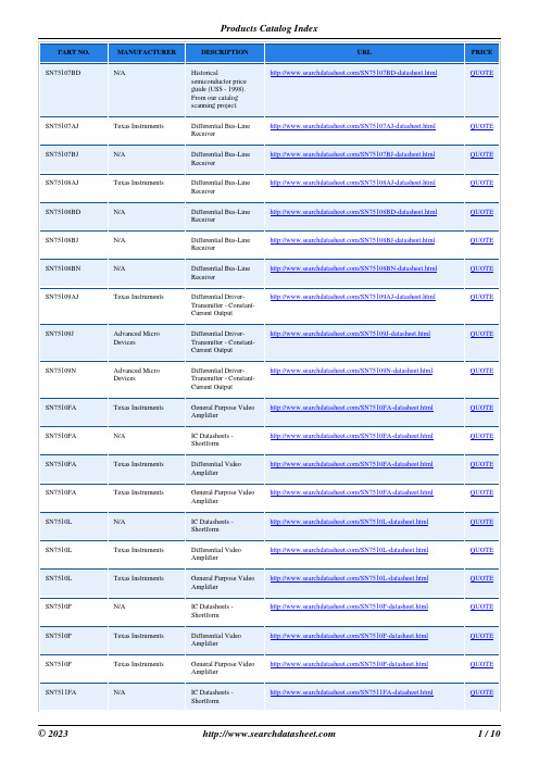
SN75107AJ SN75107BJ SN75108AJ SN75108BD SN75108BJ SN75108BN SN75109AJ
SN75109J
SN75109N
SN7510FA SN7510FA SN7510FA SN7510FA SN7510L SN7510L SN7510L SN7510P SN7510P SN7510P SN7511FA
N/A
IC Datasheets -
/SN7510L-datasheet.html
Shortform
Texas Instruments
Differential Video Amplifier
/SN7510L-datasheet.html
Advanced Micro Devices
Differential DriverTransmitter - ConstantCurrent Output
/SN75109N-datasheet.html
Texas Instruments
General Purpose Video Amplifier
Shortform
Texas Instruments
Differential Video Amplifier
/SN7510P-datasheet.html
Texas Instruments
General Purpose Video Amplifier
Differential Video Amplifier
/SN7510FA-datasheet.html
Texas Instruments
General Purpose Video Amplifier
罗斯蒙特 644 顶部接线盒和导轨安装温度变送器 说明书
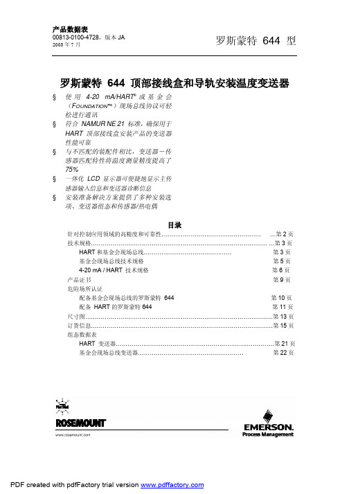
规格下限
规格上限
极限值高三倍。因此,您所拥有的设备性能很有可能要高于我们所发 所示为 644、Pt 100 RTD 传感器精确度分布,
布的技术规格要求。
温度范围 0 至 100 °C
相反,如果供应商不用过程控制对产品进行“评级”或者不承诺产品 性能达到技术规格 ± 3σ,所装运的大部分装置都将极有可能仅在所
罗斯蒙特产品不但符合其发布的技术规格要求,而且还极有可能超过
典型精度
这些要求。先进的制造工艺和统计过程的应用使技术规格符合性至少
达到± 3σ(1)。我们承诺对产品继续进行改进,以确保产品设计、可靠
性和性能逐年得到提高提高。
例如,644 型温度变送器参考精度分布如右图所示。我们的技术规格 极限值为 ± 0.15 °C,但如阴影部分所示,接近 68% 的装置其性能比
和 mV)、mA 和百分比量程。可对显示器进行配置,以在 外壳
低铜铝
选定显示项目之间进行切换。可以根据标准变送器组态在 油漆
聚氨酯
工厂对显示器设置进行预配置。使用 HART 或基金会现场 封盖 O 形环:
丁纳橡胶 N
总线通讯装置,可在现场对它们进行重新配置。
安装
湿度极限
644R 直接与墙壁或 DIN 导轨连接。将 644H 安装在一个
基金会现场总线技术规格
功能块
资源块
·资源块包含变送器物理信息,包括:可用内存、制造标
识、设备型号、软件标牌和唯一标识符。
转换块
·转换块包含实际温度测量数据,包括传感器 1 和终端温
度。包括下列信息:传感器型号和组态、工程单位、线性
化、重新测距、阻尼、温度校准和诊断。
LCD 块
·LCD 块用于配置本地显示器(如果正在使用 LCD 显示
GKN 纳铁福480
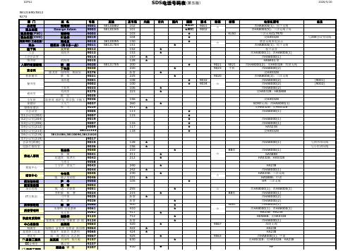
姓 名 张海涛 George Adam 张峥嵘 叶连祥 陶培泉 程佩玲(用卡多一点) 程佩玲 ( 用卡多一点 ) 吴关钦 高俊杰
直线 58120882 58120345
38120095 58121704
58121705
原号码 102 101 103 104 150 151 152 153 157 128 200 220 新增 225 108 100 106 223 156 260 911 113 115 116 117 118
西HA8000(1) 西HA8000(1) HA5888 HA5328;HA5328 HA238 西HA8000(1) HA5238;三洋无绳 HA5888;中诺 HP;三洋无绳 西HA8000(1);西HA8000(1) 西HA8000(1) 西HA8000(2) 西HA8000(2) 西HA8000(1) 西HA8000(1);西HA8000(1) HA238;HA238 HA5888;皮HA5328 西HA8000(1) 西陵无绳 HA238 HA238 西HA8000(1);中诺 皮HA5328;皮HA5328;HA238 HP HP
号码 9001 9002 9003 9019 9010 9011 9012 9013 9014 9015 俞海涛 9020 胡 捷 9030 丁伟国 9276 陈龙章 徐伟明 顾国安 9021 蔡 怡 9001 戎亦超 9002 9033 王彩凤 9275 刘剑萍 9035 陈 民 陆春茂 郝洪发 贾宗强 卫振飞 9036 9037 王玉兰 9039 张 力 9005 9007 9019 9007 9009 58121333
02PA1
SDS电话号码表(第五版) 电话号码表
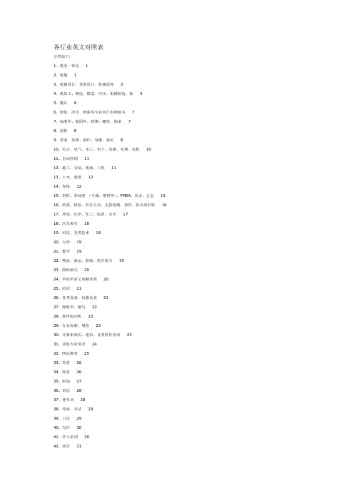
各行业英文对照表
各行业英文对照表分类如下:1、机电一体化 12、机械 13、机械设计、其他设计、机械原理 34、机加工、铸造、锻造、冲压、机械制造、钻 45、模具 66、组装、冲压、喷漆等专业词汇多种版本77、标准件、紧固件、弹簧、螺栓、轴承78、齿轮89、管道、泵阀、锅炉、容器、液压810、电力、电气、电工、电子、电路、电器、电机1011、自动控制1112、施工、安装、现场、工程1113、土木、建筑1214、焊接1215、材料、热处理(今属、塑料等)、FMEA、冶金、五金1316、质量、检验、形位公差、无损检测、探伤、供应商审核1617、环境、化学、化工、医药、安全1718、汽车相关1819、科技、各类技术1820、力学1921、数学1922、物流、海运、船舶、航空航天1923、图纸相关2024、毕业所需文章翻译类2025、纺织2126、各类设备、仪器仪表2127、缩略语、缩写2228、软件版词典2229、行业标准、规范2330、计算机相关、通信、各类软件用语2331、其他专业英语2432、网站推荐2533、外贸2634、商务2635、职场2736、语法2837、背单词2838、考级、考试2939、口语2940、写作3041、学习系列3042、谚语3143、翻译3144、其他321、机电一体化一、附件下载篇The Mechatronics Handbook, 2002 (pdf, 1230页) /read.php?tid=465882机电专业英语(pdg格式,扫描件,共294页) /read.php?tid=2341机电工程专业英语(txt) /read.php?tid=379244Oxford English for Electrical and Mechanical Engineering (PDF 35MB) /read.php?tid=433637专业(机电)词汇汇总英汉对照(20个TXT文件) /read.php?tid=447250二、非下载篇2、机械一、附件下载篇English for Technical Students (EFTS) (PDF格式,175页) /read.php?tid=431499Mechanical_Engineers_Handbook (2001年版的800多页) /read.php?tid=431032mechanical engineers handbook (共2000多页,123M, 4个PDF) /read.php?tid=4073422003版英文书籍《Mechanical_Engineers_Data_Handbook》(pdf, 354页)/read.php?tid=401526英汉机械工程大词典(PDF格式,有书签,共1324页) /read.php?tid=22515机械翻译词汇(PDF格式,超清晰版,共123页) /read.php?tid=16306機構英文專用術語(DBTEL excel多页链接,繁体) /read.php?tid=120605机械专业英语(pdf,清晰,共135页,全英文,非词典) /read.php?tid=442234Professional words (word文档,包括电工、金属材料、热机、除灰、水电、供水、消防、结构、环保) /read.php?tid=39253机械词语翻译(pdf格式,共123页) /read.php?tid=2432机械名词解释(word文档,2000多个) /read.php?tid=57994机械工程名词PDF版(1、2分别为148,243页) /read.php?tid=412306赛尔集团内部资料-最新实用机械专业英语汇总pdf格式/read.php?tid=1832711楼A-Z词汇(word 文档) /read.php?tid=20373A-G字母开头的机械英语单词(几个TXT文档) /read.php?tid=194246机械英语Word 版整理/read.php?tid=30666分享我收集的机械英语(4个word文档,与其他资料有重复) /read.php?tid=97007机械行业部分英汉对照(与其它机械英语有重复) /read.php?tid=53521机械词汇(几个txt) /read.php?tid=438448机械专业英语词汇(pdf, 15页) /read.php?tid=299923机械专业英语(txt) /read.php?tid=399140机械专业英语(word, 26页) /read.php?tid=247505机械专业英语(word, 9页) /read.php?tid=246588机械专业英语词典(1楼,DOS界面) /read.php?tid=435032机械英语生词本出炉/read.php?tid=442910机械英语(6个文档) /read.php?tid=413955机械专业词汇(word文档,300页) /read.php?tid=391269一些机械英语词汇(word, 99页,有汽车的,外贸的,热处理的等,不是很全) /read.php?tid=398277本人多年收集的机械英语集(10个word&txt文档) /read.php?tid=166962已整理,比较全的机械专业英语(7个文档合集,有贴图) /read.php?tid=342834机械常用英语单词(word文档,82页,按笔划排序,6楼补充资料73页word) /read.php?tid=381169机械通用词汇(整理过的,word,50页) /read.php?tid=387352《机械专业英语词汇》(共218页word) /read.php?tid=287422机械英语对照(word, 68页) /read.php?tid=342137英汉对照机械术语(word, 8页) /read.php?tid=1933122099个机械方面的英语词汇(pdf, 50页) /read.php?tid=179413机械相关专业英语(word, 17页) /read.php?tid=464867我在网上收集了一些关于机械翻译的资料/read.php?tid=352006《汉英词典》机械类专用词汇(word, 按笔划排序,50页) /read.php?tid=248469[机械资料]机械英语名词解释(PDF, 50页) /read.php?tid=2277机械中的常用英语(word文档,共119页) /read.php?tid=244162机械专业英语词汇自己整理和收集的/read.php?tid=277036机械专业英语词汇汇编(5个txt) /read.php?tid=211858Mechanical Engineering phrases chinese-english reference(EXCEL) /read.php?tid=284092machinery component maintenance and repair (一本关于机械设备维护的好书,PDF,全英文,641页) /read.php?tid=445276词根记忆法& 一些机械词汇(2个word文档) /read.php?tid=350184机械中英习题(word, 13页) /read.php?tid=2338基础机械德语教程(pdf, 非清晰版) /read.php?tid=444990机械德语基础词汇!!(汽车化工机械类)/read.php?tid=444992机械专业英语(word版)/read.php?tid=477622二、非下载篇机械英文/read.php?tid=17789机械英语汇总词汇/read.php?tid=27673机械英语汇总/read.php?tid=2431机械类英语汇总/read.php?tid=370324机械单词(与很多资料有重复内容) /read.php?tid=69886机械词汇/read.php?tid=181418机械零件中英词汇对照/read.php?tid=199202机械英语/read.php?tid=213121机械专业英语/read.php?tid=104444机械词汇/read.php?tid=261504一些机械常用英汉对照词汇/read.php?tid=445397专业英语/read.php?tid=443728机械英语词汇(综合型)/read.php?tid=419019机械类相关英语大全(3个word文档,资料与其他资料有重复) /read.php?tid=416619机械英语词汇(a开头) /read.php?tid=381959机械英语11 /read.php?tid=405004新查了些机械方面的英语(1楼焊接方面) /read.php?tid=404796机械工程材料常用词汇/read.php?tid=252060十几年老翻译专业词汇/read.php?tid=124337机械类专利翻译词汇汇总(大约3000个)/read.php?tid=464222机械.中英文对照名词解释/read.php?tid=218731机械专业词汇表/read.php?tid=233371机械专业英语词汇/read.php?tid=288646英汉对照机械术语/read.php?tid=485112机械方面的词汇/read.php?tid=4868333、机械设计、其他设计、机械原理一、附件下载篇机械设计中英文词汇对照(三个word文档) /read.php?tid=21358机械设计名词术语中英文对照表(txt格式) /read.php?tid=15853机械设计名词术语中英文对照表(pdf格式,共35页,A-Z) /read.php?tid=38593机械设计名词术语中英文对照(pdf格式,共8页) /read.php?tid=351677机械名词术语翻译(word, 31页) /read.php?tid=166385机械设计专业术语的英语翻译(word, 16页) /read.php?tid=377426机械设计英语术语大全(word, 9页) /read.php?tid=380689机械设计常用词汇(意大利-英语-汉语, pdf, 96页) /read.php?tid=387161Standards for engineering design and manufacturing(12个pdf) /read.php?tid=428163Mechanical Engineering Design 7th edtion (全英文,pdf格式,共18章,400多页,主要是一些机械设计中的计算实例) /read.php?tid=435808Engineering Design in Three Dimension(大学3D设计书本资料键盘录入) /read.php?tid=379683TANK DESIGN CALCULATION FOR ENGLISH(PDF 格式) /read.php?tid=110067Designing Capable and Reliable Products (设计可行、可靠的产品, 408 pages) /read.php?tid=431044 Hydraulic seal of cylinder (pdf by Busak+Shamban) /read.php?tid=425058机械原理(英文10个ppt)/read.php?tid=150854Designing with Plastic(PDF, 84页) /read.php?tid=480735二、非下载篇机械设计及周边其他用语英汉对照/read.php?tid=2443机械设计名词术语中英文对照表相同资料不同格式资料合并/read.php?tid=16775机械设计工作人员常用软件大会集/read.php?tid=465505机械设计部分外语/read.php?tid=11261平面设计/read.php?tid=2453机械类常用英语:机械设计类/read.php?tid=361300机械原理常用词汇/read.php?tid=448322机械原理部分外语/read.php?tid=11259机械制图部分外语/read.php?tid=11263机械製图常用词汇/read.php?tid=4483124、机加工、铸造、锻造、冲压、机械制造、钻一、附件下载篇金属加工专业词汇(PDF, 10页) /read.php?tid=2301金属工艺学专业词汇(和切削的相关度比较高, word, 6页) /read.php?tid=179842 1楼加工中心英语(word文档,7页,同机床行业常用英文对照/read.php?tid=2282) /read.php?tid=2454机械加工工艺装备基本术语--英-汉/read.php?tid=421106机械加工常用基础英语名词术语翻译对照大全(txt) /read.php?tid=318365机械加工类英语(word, 33页) /read.php?tid=320330Machinery's Handbook 27th Edition /read.php?tid=423917Cutting Tool Applications (18个PDF,全英文) /read.php?tid=419582机床和铣床翻译(word, 2页) /read.php?tid=315914工艺词汇(中英文,word双排,13页) /read.php?tid=177569常用加工机械(word, 2页) /read.php?tid=227191Machining课(机械加工)时加国老师用的英文讲义/read.php?tid=124463英汉金属塑性加工词典(pdf, 287MB) /read.php?tid=312971铸造术语(中英文对照)(word文档,共42页) /read.php?tid=39941铸件教程(英文, pdf, 179页)/read.php?tid=356857铸造常用词汇(word, 2页) /read.php?tid=192787铸造名词术语GB5611-1998 (PDF,182页)/read.php?tid=267888常用铸造词汇的中英文对照和解释(word,1页, PDF11页) /read.php?tid=251220铸造学专业英语词汇(1~31卷,word, 共128页)/read.php?tid=464263Die Casting Alloy Data(pdf, 18页) /read.php?tid=463550What is High Pressure Die Casting(word, 25页) /read.php?tid=338307die casting design (全英文版的书,185页) /read.php?tid=426333Rapid Die Heating for Low-Stress Die Attach(pdf, 10页) /read.php?tid=284965锻铸造关连词汇(word, 4页) /read.php?tid=79892锻铸造关连词汇(word, 13页) /read.php?tid=481947HOW TO BUY FORGINGS (pdf, 6页, 锻造) /read.php?tid=403834冲压英语(word文档,2页) /read.php?tid=2274冲压专业在实践中常用的英语(word, 5页) /read.php?tid=2461Tool-Engineering-Calculator (excel格式) /read.php?tid=390775sour drilling material (pdf, 12页) /read.php?tid=123726机械制造专业英语(章跃,机械工业出版社) /read.php?tid=411529机械制造业翻译词汇/read.php?tid=318360钻井液管汇说明书改动(word, 7页) /read.php?tid=443249 (1楼)铸造术语标准翻译(excel多页分类) /read.php?tid=472114Machining and Metalworking Handbook (McGraw-Hill Handbooks,PDF,976页) /read.php?tid=487100机床行业常用英文对照(同加工中心英语(word文档,7页) /read.php?tid=2454) /read.php?tid=2282二、非下载篇机械加工常用工具英汉对照/read.php?tid=448289常用英语:加工方法/read.php?tid=392537机加英语(一)/read.php?tid=240675机床英汉对照/read.php?tid=485105加工中心英语/read.php?tid=2311/read.php?tid=470615常用加工机械英语/read.php?tid=104447机加工专业(单词/词组)中英对照/read.php?tid=446285铸造常用词中英文对照及简释/read.php?tid=55445铸造、滚动轴承、机床行业常用词中英文对照及简释/read.php?tid=141823铸造厂评估报告英文版/read.php?tid=213697机械铸造类专业术语/read.php?tid=470504锻铸造关连用语/read.php?tid=485115铸件涂层coating of casting /read.php?tid=217929连铸英语/read.php?tid=254939冲压机械及周边关连用语英汉对照/read.php?tid=115797冲压加工工序名称中英文对照表/read.php?tid=141042冲压英语/read.php?tid=2447机械类常用英语系列之冲压模具-零件类/read.php?tid=248000机械工具英语/read.php?tid=153292机械类常用英语:砂轮用语/read.php?tid=418978砂轮用语中英文对照/read.php?tid=111042粗切削与精切削(中英)/read.php?tid=260042线切割放电加工关连用语中英文对照/read.php?tid=113644制造业中常用的英文缩写/read.php?tid=441031常用刀具词汇英语/read.php?tid=389573制造业常用英语词汇/read.php?tid=89976机械类常用英语之射出成形关联用语/read.php?tid=1126395、模具一、附件下载篇模具术语(word文档,47页) /read.php?tid=2294 1楼模具(机械)英语词汇表(word文档,131页) /read.php?tid=2294 2楼模具類相關英語/read.php?tid=58313模具英语(excel格式) /read.php?tid=11111 (1楼)注塑模具英語(pdf,共7页) /read.php?tid=212266机械英语\模具\模具英语词汇表(pdf格式,共10页) /read.php?tid=211179模具相关英语(word文档,38页)/read.php?tid=448135flat die and pocket die(一篇关于冲模的英文论文) /read.php?tid=441754mold design(21页,PDF) /read.php?tid=434679拉深模设计中拉深壁起皱的分析(原英文资料和翻译) /read.php?tid=429892useful knowledge (模流1) (pdf, 256页) /read.php?tid=401659模具英語單詞(pdf, 19页) /read.php?tid=401653模具专业英语(txt) /read.php?tid=125729塑料挤压模具设计(英文版,21页,PDF)/read.php?tid=254689Progressive_die_sequence_design_for_deep_drawing_round_cups_using_finite_element_analysis (模具类的英文文章. 宁言军,PDF 4页) /read.php?tid=284941模具英语(5个word,1个PDF,1个DWG) /read.php?tid=206659二、非下载篇冲压模具/read.php?tid=29172冲模术语(中英对照)/read.php?tid=263934模具专业英语/read.php?tid=2273模具词汇/read.php?tid=37378模具常用刀具与工作法用语/read.php?tid=2336模具钢材及零件英语/read.php?tid=2294模具工程常用词汇/read.php?tid=55116常用模具英语/read.php?tid=2429模具成形不良用语中英文对照/read.php?tid=111038各种模具常用成形方式中英文对照/read.php?tid=112641各式模具分类用语中英文对照/read.php?tid=247995模具英语/read.php?tid=262744机械英语词汇之模板、零件、塑件&模具/read.php?tid=349433各式模具分类用语中英文对照/read.php?tid=431994模具成形不良用语英汉对照/read.php?tid=2442模具相关英语/read.php?tid=5639模具术语(英汉对照)/read.php?tid=260587挤出机、锁模机及立式注塑成型机技术参数型号规格翻译/read.php?tid=471461成型工艺、熔胶段工艺流程及条件介绍/read.php?tid=471452塑料模具常用的英日中词汇汇总/read.php?tid=4873076、组装、冲压、喷漆等专业词汇多种版本一、附件下载篇机械专业术语(组装、冲压、喷漆等专业词汇,PDF格式) /read.php?tid=2281机械专业术语(word文档,组装、冲压、喷漆等专业词汇) /read.php?tid=2278(/read.php?tid=2288重复)模具相关英语(word, 组装、冲压、喷漆等专业词汇繁体版) /read.php?tid=13611机械与工厂英语(word, 39页,前31页同组装、冲压、喷漆等词汇) /read.php?tid=244349机械与工厂英语(word, 共76页,前57页同组装、冲压、喷漆等专业词汇) /read.php?tid=52513常用的机械英语词汇(2个word文档,机械词汇表-模具10页;综合15页大部分重复组装、冲压、喷漆等专业词汇) /read.php?tid=415085二、非下载篇7、标准件、紧固件、弹簧、螺栓、轴承一、附件下载篇标准件中英文对照表紧固件中英文对照表扣件中英文对照表(PDF, 9页,宁波龙益金属工业有限公司) /read.php?tid=38812机械,钣金,常用紧固件英语(3个word文档) /read.php?tid=244613紧固件常用英文对照(pdf, 5页) /read.php?tid=465086国家紧固件标准GBT 与汉语、英语对照表共享(word, 6页) /read.php?tid=265356常用弹簧中英文对照表(word文档,2页) /read.php?tid=421137VDI2230 (关于如何计算螺栓连接方面的,一边是德文的,一边是英文的,主要是讲德语地区的应用标准) /read.php?tid=402157中外螺纹查询工具(exe直接运行,汉化版见14楼) /read.php?tid=120668行业标准规范英汉对照/read.php?tid=391097轴承的英文名称(PDF, 5页) /read.php?tid=244641Stainless Steel Fasteners Design Handbook (pdf,23页) /read.php?tid=403826二、非下载篇标准件的行业对照/read.php?tid=406559行业标准规范英汉对照/read.php?tid=141488紧固件类英语词汇/read.php?tid=2299紧固件专业英语词汇/read.php?tid=37299螺丝产品名称(线材)中英文对照(简体、繁体) /read.php?tid=113640螺纹知识/read.php?tid=438441螺丝产品名称中英文对照(螺丝螺) /read.php?tid=2439THREAD /read.php?tid=378061螺丝相关的英语(材料,加工,设备。
EMC
Us
-150
V
Ua
14
V
t1
100
µs
t4
10
ms
t5
90
ms
td
0
Ω
测试时间:1h
Us
+100
V
Ua
27
V
t1
100
µs
t4
10
ms
t5
90
ms
td
0.1
µs
tr
5
ns
Ri
50
Ω
测试时间:1h
Us
-7
V
Ua
6
V
Ub
14
V
t7
100
ms
t10
10
ms
t8
50
ms
t9
20
s
t11
报告编号 Rep No.
测试结果描述 测试中 EUT 停止工作 工作正常 工作正常 工作正常 工作正常 工作正常 工作正常
测试后 工作正常 工作正常 工作正常 工作正常 工作正常 工作正常 工作正常
判定
合格 合格 合格 合格 合格 合格 合格
试验结论: 被测样品符合 ISO 7637-2:2008 及企业技术要求的瞬变脉冲传导抗扰度测试。
30 ~ 54 70 ~ 87 87 ~ 108
标准限值(峰值) (dBµV) 3
79 65 65 49 93
详细数据
详见图 1,图 2 详见图 1,图 2 详见图 1,图 2 详见图 1,图 2 详见图 1,图 2 详见图 1,图 2
结论
合格 合格 合格 合格 合格 合格
试验结论: 被测样品符合 GB 18655-2002 和企业技术要求的电源输入端传导骚扰电压等级 3 的限值。
聚合物锂电池401520规格书

egrahC dradnatS smetI
电充准标
1 .O N
能性电放充 scitsiretcarahc lacirtcelE 1.4
airetirC ecnamrofreP lleC yrettaB.4
试测及查检能性芯电
41 fo 4 :EGAP A : .VER 810 :.ON COD
司公限有技科子电达立迅海珠
寸尺芯电 noisnemiD lleC 量重芯电 thgieW lleC 度温存储 erutarepmet egarotS 度温作工 erutarepmet gnitarepO 压电止截电放 egatlov ffo-tuc egrahcsiD 流电电放大最 tnerruc egrahcsid.xaM 流电电充大最 tnerruc egrahc.xaM 间时电充 emit gnigrahC 法方电充准标 dohtem gnigrahC dradnatS 流电电充 tnerruc egrahC 量容称标 yticapac lanimoN 压电称标 egatlov lanimoN smetI 压电电充 egatlov egrahC
认确户客
准批
核审
定制
025154 SCI
025154 SCI �号
:ledoM
型
�芯电�书认确格规品产 )lleC(teehS lavorppA noitacificepS
41 fo 1 :EGAP A : .VER :.ON COD 810
司公限有技科子电达立迅海珠
31 21 11 01 01 9 8 7 7 6 5 4 3 3 3
定确商协方双经须�项事的及提未中书明说本何任 .NUJOUHZ dna remotsuc eht neewteb derrefnoc eb dluohs revoc ton seod noitacificeps siht taht srettam ynA 项事它其 srehtO )b
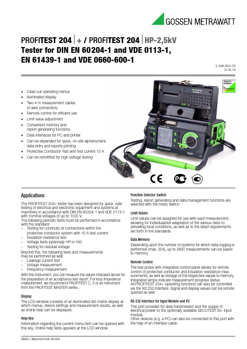
PROFITEST 204 + PROFITEST 204 HP-2,5kV Tester for …
Int. Resist. RI
Meas. Uncertainty
Intrinsic Uncertainty
Overload Capacity Duration
0 85 m 100 Protective 10 330 m 85 999 m 1 m Conductor Resistance 1.00 9.99 1.00 9.99 10 m RSL 10.0 25.0 10.0 25.0 100 m
PROFITEST 204+ / PROFITEST 204HP-2,5kV Tester for DIN EN 60204-1 and VDE 0113-1, EN 61439-1 and VDE 0660-600-1
3-348-802-03 21/8.14
• • • • • • • • • •
1200 V
cont.
—
1 M 10 M
—
(5% rdg. +2 d) (10% rdg. +2 d) (20% rdg. +2 d)
0.00 9.99 mA
0.2 9.9 mA 0.01 mA
—
—
—
—
2 k (8.6% rdg. +9 d) (5% rdg. + 5 d)
250 V
U 2)
(3% rdg. + 5 d)
0 9.99 V* 10.0 12.0 V 0 999 k
—
0.01 V 0.1 V 1 k 100 k 1 M
川仪横河EJA118

EJA118W 、EJA118N和 EJA118Y型隔膜密封式差压变送器电源影响:±0.005%/V(21.6~32V DC ,350Ω)安 装:变送器:2-inch 管道安装隔膜密封件:法兰安装安装法兰规格参阅“型号及规格代码一览表”ANSI 规格的法兰与垫片接触的一面,进行锯齿形加工(根据ANSI B16.5)防水结构IEC IP67 、 NEMA 4X 和JISC0920防浸型标准技术规格密封隔膜是用于防止管道中的介质直接进入差压变送器里的压力传感器组件中,它与变送器之间是靠注满流体的毛细管连接起来的。
横河川仪有限公司YOKOGA WA SIC HU A N ◆GS 01C22H01-00CYR EJA118W 、EJA118N 和 EJA118Y 隔膜密封式 差压变送器用于测量液体、气体和蒸汽的流量、液位、密度和压力,然后输出与测得的差压相对应的4~20mA DC 信号。
EJA118W 、EJA118N TM TM 和EJA 118Y 可与 BRAIN 手操器、 CE NT U M CS 、 F ieldMate 、YHC4150、HA R T 37 5 互相通讯, 通过它们进行设定、监控等。
GeneralSpecifications一般规格书精 度:参阅表2-1,2-2和2-3环境温度:注:环境温度极限必须在注入液工作温度范围内,见表1(参 见防爆型种类附加规格)-40~85℃(-40~185 °F )(一般型 ) -30~80℃(-22~176 °F )[带数字式表头]环境温度的影响:参阅表2-1,2-2和2-3过程温度范围参阅表1(选用隔爆时参见附加规格代码)接液温度:参阅表1环境湿度:5~100%RH (40℃时)工作压力:2.7kPa abs (20mmHg abs )~法兰的额定工作压力大气压以下的参阅图2静压影响:参阅表2-1,2-2和2-3输出信号“ ”测量范围:膜盒量 程范 围M H2.5~100kPa(250~10000mmH O )2-100~100kPa(-10000~10000mmH O )225~500kPa 2(0.25~5kgf/cm )-500~500kPa 2(-5~5kgf/cm )4~20mA DC,带数字通讯的2线制10.5~42V DC(普通型和隔爆型)10.5~30V DC ( 本安型、n 型或非易燃型)10.5~32V DC(带避雷保护时)电源电压“ ”出错报警注:只适用于输出信号代码为 D 和 E 时CPU 或硬件出错时输出状态上限输出:110%≥21.6mA DC(标准)下限输出:-5%,≤3.2mA DC - 2 .5%,≤3.6mADC(适用于代码F1)“ ”10.5~28V DC(TIIS 本安防爆)通信距离:2km,使用CEV 电缆或者PVC 电缆时负载电容:≤0.22μF 负载电感:≤3.3mH与电源线的间距:≥15cm连接于接受电阻上的接收仪表的输入阻抗在2.4kHZ 时,≥10k[选用本安时参见附加规格代码]通信线路条件“ ”电源电压:16.4~42V DC(16.4~30V DC)负载电阻:参阅图1注:如果是本安型变送器,外部负载电阻应包括安全栅电阻97带“ ”符号的参考FF现场总线GS01C22T02-00CY 和PROFIBUS 现场总线GS01C22T03-00CY2放大器外壳铝合金铸件或JIS SCS14A 不锈钢变送器材质容室法兰:JIS SCS14A螺栓、螺母:见型号规格表隔膜及其它接液部件:参阅“型号与规格代码一览表”毛细管:JIS SUS316保护管:JIS SUS304oPVC 屏蔽(PVC 的最大使用温度:100℃)(212F )注入液:参阅表 1隔膜密封件材质:当毛细管长 5m ,注入液的代码为A ,过程法兰为3英寸时,在正常温度下取得的值。
JNJ-40411813-SDS-MedChemExpress
Inhibitors, Agonists, Screening LibrariesSafety Data Sheet Revision Date:Oct.-01-2018Print Date:Oct.-01-20181. PRODUCT AND COMPANY IDENTIFICATION1.1 Product identifierProduct name :JNJ-40411813Catalog No. :HY-15748CAS No. :1127498-03-61.2 Relevant identified uses of the substance or mixture and uses advised againstIdentified uses :Laboratory chemicals, manufacture of substances.1.3 Details of the supplier of the safety data sheetCompany:MedChemExpress USATel:609-228-6898Fax:609-228-5909E-mail:sales@1.4 Emergency telephone numberEmergency Phone #:609-228-68982. HAZARDS IDENTIFICATION2.1 Classification of the substance or mixtureNot a hazardous substance or mixture.2.2 GHS Label elements, including precautionary statementsNot a hazardous substance or mixture.2.3 Other hazardsNone.3. COMPOSITION/INFORMATION ON INGREDIENTS3.1 SubstancesSynonyms:JNJ40411813;JNJ 40411813Formula:C20H25ClN2OMolecular Weight:344.88CAS No. :1127498-03-64. FIRST AID MEASURES4.1 Description of first aid measuresEye contactRemove any contact lenses, locate eye-wash station, and flush eyes immediately with large amounts of water. Separate eyelids with fingers to ensure adequate flushing. Promptly call a physician.Skin contactRinse skin thoroughly with large amounts of water. Remove contaminated clothing and shoes and call a physician.InhalationImmediately relocate self or casualty to fresh air. If breathing is difficult, give cardiopulmonary resuscitation (CPR). Avoid mouth-to-mouth resuscitation.IngestionWash out mouth with water; Do NOT induce vomiting; call a physician.4.2 Most important symptoms and effects, both acute and delayedThe most important known symptoms and effects are described in the labelling (see section 2.2).4.3 Indication of any immediate medical attention and special treatment neededTreat symptomatically.5. FIRE FIGHTING MEASURES5.1 Extinguishing mediaSuitable extinguishing mediaUse water spray, dry chemical, foam, and carbon dioxide fire extinguisher.5.2 Special hazards arising from the substance or mixtureDuring combustion, may emit irritant fumes.5.3 Advice for firefightersWear self-contained breathing apparatus and protective clothing.6. ACCIDENTAL RELEASE MEASURES6.1 Personal precautions, protective equipment and emergency proceduresUse full personal protective equipment. Avoid breathing vapors, mist, dust or gas. Ensure adequate ventilation. Evacuate personnel to safe areas.Refer to protective measures listed in sections 8.6.2 Environmental precautionsTry to prevent further leakage or spillage. Keep the product away from drains or water courses.6.3 Methods and materials for containment and cleaning upAbsorb solutions with finely-powdered liquid-binding material (diatomite, universal binders); Decontaminate surfaces and equipment by scrubbing with alcohol; Dispose of contaminated material according to Section 13.7. HANDLING AND STORAGE7.1 Precautions for safe handlingAvoid inhalation, contact with eyes and skin. Avoid dust and aerosol formation. Use only in areas with appropriate exhaust ventilation.7.2 Conditions for safe storage, including any incompatibilitiesKeep container tightly sealed in cool, well-ventilated area. Keep away from direct sunlight and sources of ignition.Recommended storage temperature:Powder-20°C 3 years4°C 2 yearsIn solvent-80°C 6 months-20°C 1 monthShipping at room temperature if less than 2 weeks.7.3 Specific end use(s)No data available.8. EXPOSURE CONTROLS/PERSONAL PROTECTION8.1 Control parametersComponents with workplace control parametersThis product contains no substances with occupational exposure limit values.8.2 Exposure controlsEngineering controlsEnsure adequate ventilation. Provide accessible safety shower and eye wash station.Personal protective equipmentEye protection Safety goggles with side-shields.Hand protection Protective gloves.Skin and body protection Impervious clothing.Respiratory protection Suitable respirator.Environmental exposure controls Keep the product away from drains, water courses or the soil. Cleanspillages in a safe way as soon as possible.9. PHYSICAL AND CHEMICAL PROPERTIES9.1 Information on basic physical and chemical propertiesAppearance White to off-white (Solid)Odor No data availableOdor threshold No data availablepH No data availableMelting/freezing point No data availableBoiling point/range No data availableFlash point No data availableEvaporation rate No data availableFlammability (solid, gas)No data availableUpper/lower flammability or explosive limits No data availableVapor pressure No data availableVapor density No data availableRelative density No data availableWater Solubility No data availablePartition coefficient No data availableAuto-ignition temperature No data availableDecomposition temperature No data availableViscosity No data availableExplosive properties No data availableOxidizing properties No data available9.2 Other safety informationNo data available.10. STABILITY AND REACTIVITY10.1 ReactivityNo data available.10.2 Chemical stabilityStable under recommended storage conditions.10.3 Possibility of hazardous reactionsNo data available.10.4 Conditions to avoidNo data available.10.5 Incompatible materialsStrong acids/alkalis, strong oxidising/reducing agents.10.6 Hazardous decomposition productsUnder fire conditions, may decompose and emit toxic fumes.Other decomposition products - no data available.11.TOXICOLOGICAL INFORMATION11.1 Information on toxicological effectsAcute toxicityClassified based on available data. For more details, see section 2Skin corrosion/irritationClassified based on available data. For more details, see section 2Serious eye damage/irritationClassified based on available data. For more details, see section 2Respiratory or skin sensitizationClassified based on available data. For more details, see section 2Germ cell mutagenicityClassified based on available data. For more details, see section 2CarcinogenicityIARC: No component of this product present at a level equal to or greater than 0.1% is identified as probable, possible or confirmed human carcinogen by IARC.ACGIH: No component of this product present at a level equal to or greater than 0.1% is identified as a potential or confirmed carcinogen by ACGIH.NTP: No component of this product present at a level equal to or greater than 0.1% is identified as a anticipated or confirmed carcinogen by NTP.OSHA: No component of this product present at a level equal to or greater than 0.1% is identified as a potential or confirmed carcinogen by OSHA.Reproductive toxicityClassified based on available data. For more details, see section 2Specific target organ toxicity - single exposureClassified based on available data. For more details, see section 2Specific target organ toxicity - repeated exposureClassified based on available data. For more details, see section 2Aspiration hazardClassified based on available data. For more details, see section 212. ECOLOGICAL INFORMATION12.1 ToxicityNo data available.12.2 Persistence and degradabilityNo data available.12.3 Bioaccumlative potentialNo data available.12.4 Mobility in soilNo data available.12.5 Results of PBT and vPvB assessmentPBT/vPvB assessment unavailable as chemical safety assessment not required or not conducted.12.6 Other adverse effectsNo data available.13. DISPOSAL CONSIDERATIONS13.1 Waste treatment methodsProductDispose substance in accordance with prevailing country, federal, state and local regulations.Contaminated packagingConduct recycling or disposal in accordance with prevailing country, federal, state and local regulations.14. TRANSPORT INFORMATIONDOT (US)This substance is considered to be non-hazardous for transport.IMDGThis substance is considered to be non-hazardous for transport.IATAThis substance is considered to be non-hazardous for transport.15. REGULATORY INFORMATIONSARA 302 Components:No chemicals in this material are subject to the reporting requirements of SARA Title III, Section 302.SARA 313 Components:This material does not contain any chemical components with known CAS numbers that exceed the threshold (De Minimis) reporting levels established by SARA Title III, Section 313.SARA 311/312 Hazards:No SARA Hazards.Massachusetts Right To Know Components:No components are subject to the Massachusetts Right to Know Act.Pennsylvania Right To Know Components:No components are subject to the Pennsylvania Right to Know Act.New Jersey Right To Know Components:No components are subject to the New Jersey Right to Know Act.California Prop. 65 Components:This product does not contain any chemicals known to State of California to cause cancer, birth defects, or anyother reproductive harm.16. OTHER INFORMATIONCopyright 2018 MedChemExpress. The above information is correct to the best of our present knowledge but does not purport to be all inclusive and should be used only as a guide. The product is for research use only and for experienced personnel. It must only be handled by suitably qualified experienced scientists in appropriately equipped and authorized facilities. The burden of safe use of this material rests entirely with the user. MedChemExpress disclaims all liability for any damage resulting from handling or from contact with this product.Caution: Product has not been fully validated for medical applications. For research use only.Tel: 609-228-6898 Fax: 609-228-5909 E-mail: tech@Address: 1 Deer Park Dr, Suite Q, Monmouth Junction, NJ 08852, USA。
JK-P系列规格书 电池保护片
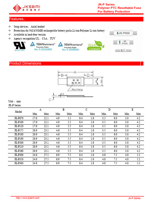
JK-P SeriesPolymer PTC Resettable FuseFor Battery Protection Features:✧Strap devices,Axial leaded✧Protection for NiCd/NiMH rechargesble battery packs,Li-ion/Polymer Li-ion battery✧Available in lead-free version✧Agency recognition:UL、CSA、TUVProduct DimensionsUnit:mmJK-P SeriesModelA B C D EMin Max Min Max Min Max Min Max Min MaxJK-P07017.022.1 4.9 5.50.4 1.0 3.5 6.0 3.8 4.2 JK-P10017.022.1 4.9 5.50.4 1.0 3.5 6.0 3.8 4.2 JK-P12017.022.1 4.9 5.50.4 1.0 3.5 6.0 3.8 4.2 JK-P17520.923.1 4.6 5.50.4 1.0 3.5 6.0 3.8 4.2 JK-P18020.923.1 4.6 5.50.4 1.0 3.5 6.0 3.8 4.2 JK-P19020.923.1 4.6 5.50.4 1.0 3.5 6.0 3.8 4.2 JK-P20020.923.1 4.6 5.50.4 1.0 3.5 6.0 3.8 4.2 JK-P21020.923.1 4.6 5.50.4 1.0 3.5 6.0 3.8 4.2 JK-P26020.923.1 4.6 5.50.4 1.0 3.5 6.0 3.8 4.2 JK-P30024.027.5 6.97.50.4 1.0 4.07.5 4.8 5.2 JK-P35024.027.5 6.97.50.4 1.0 4.07.5 4.8 5.2 JK-P38024.027.5 6.97.50.4 1.0 4.07.5 4.8 5.2JK-P45024.027.59.810.50.4 1.0 4.07.5 4.8 5.2 JK-P55024.027.59.810.50.4 1.0 4.07.5 4.8 5.2 JK-P60027.129.113.914.50.4 1.0 4.1 5.5 5.9 6.6 JK-P73027.129.113.914.50.4 1.0 4.1 5.5 5.9 6.6 JK-P90045.447.67.98.50.4 1.0 4.6 6.2 5.9 6.1 JK-P141058.060.013.414.00.4 1.0 4.2 5.8 5.9 6.1 Thermal Derating Chart-IH(A)JK-P SeriesModelMaximum ambient operating temperatures(℃)-40-20025405060708085JK-P070 1.1 1.00.80.70.50.40.30.20.20.1 JK-P100 1.8 1.6 1.4 1.00.80.70.60.40.30.2 JK-P120 1.9 1.7 1.5 1.2 1.00.90.80.60.50.4 JK-P175 2.5 2.2 2.0 1.75 1.4 1.3 1.2 1.00.90.8 JK-P180 2.6 2.3 2.1 1.8 1.4 1.3 1.2 1.00.90.8 JK-P190 2.8 2.5 2.3 1.9 1.5 1.4 1.3 1.10.90.8 JK-P200 3.1 2.8 2.5 2.0 1.7 1.5 1.4 1.2 1.00.9 JK-P210 3.3 3.0 2.7 2.1 1.8 1.6 1.5 1.3 1.1 1.0 JK-P260 3.8 3.4 3.1 2.6 2.2 2.0 1.9 1.7 1.4 1.3 JK-P300 5.1 4.4 3.7 3.0 2.3 1.9 1.6 1.20.90.7 JK-P350 5.3 4.8 4.3 3.5 3.0 2.7 2.5 2.1 1.8 1.7 JK-P380 5.4 4.9 4.4 3.8 3.3 3.0 2.8 2.5 2.3 2.1 JK-P420 6.3 5.7 5.1 4.2 3.6 3.3 3.0 2.6 2.2 2.1 JK-P450 6.5 5.8 5.3 4.5 3.9 3.6 3.3 2.9 2.6 2.4 JK-P5507.6 6.9 6.2 5..5 4.7 4.3 4.0 3.6 3.2 3.0 JK-P6008.77.87.1 6.0 5.2 4.7 4.4 3.9 3.4 3.2 JK-P73010.59.58.67.3 6.3 5.7 5.4 4.7 4.2 4.0 JK-P90012.711.4109.07.5 6.8 6.2 5.5 4.9 4.5 JK-P141019.917.815.714.111.810.89.78.77.77.2Typical Time-to-Trip Charts at25℃A---JK-P350B---JK-P420C---JK-P450D---JK-P550E---JK-P600F---JK-P730G---JK-P900H---JK-P1410Hold CurrentProduct SeriesElectrical CharacteristicI hold I trip V max I max P d I tripT trip R min R max R 1max Model (A)(A)(V)(A)(W)Current(A)Time(S)(Ω)(Ω)(Ω)JK-P0700.70 1.4516100 1.60 3.5 5.010*******JK-P100 1.00 2.5016100 1.60 5.0 5.070130260JK-P120 1.20 2.7016100 1.60 6.0 5.060120240JK-P175 1.75 3.8016100 1.608.5 5.03065130JK-P180 1.80 3.8016100 1.609.0 5.03060120JK-P190 1.90 4.2016100 1.609.5 5.0254590JK-P200 2.00 4.4016100 1.6010.0 5.0204080JK-P210 2.10 4.4016100 1.6010.5 5.0203570JK-P260 2.60 5.2016100 1.6013.0 5.0153060JK-P300 3.00 6.3024100 2.4015.0 5.0153162JK-P350 3.507.0024100 2.4017.5 5.0173162JK-P380 3.807.6024100 2.4019.0 5.0132244JK-P420 4.208.3024100 2.0021.0 5.0122448JK-P450 4.509.0020100 2.0022.5 5.0112040JK-P550 5.5010.5020100 2.0027.5 5.091632JK-P600 6.0011.7020100 2.8030.0 5.071428JK-P7307.3014.1020100 3.3036.5 5.051224JK-P9009.0016.7020100 3.8045.0 5.061020JK-P141014.1026.20201006.0070.55.03510Marking SystemJK -P □□□Jinke MarkTest Procedures And RequirementsTest Test Conditions Accept/Reject Criteria Resistance In still air@25℃R min≤R≤R maxTime to Trip Specified current,V max,25℃Tmaximum Time to Trip Hold Current30min,at I H No tripTrip Cycle Life Vmax,Imax,1000cycles No arcing or burning Trip Endurance Vmax,24hours No arcing or burning Physical Characteristics and Environmental SpecificationsPhysical CharacteristicsLead material0.125mm nominal hickness,quarter-hard nickelTape material PolyesterEnvironmental SpecificationsTest Conditions Resistance Change Passive aging70℃,1000hours±10%Humidity aging85℃/85%RH.7days±5%Vibration MIL-STD-883C,Test Condition A No chageElectrical SpecificationsI hold=Hold current:maximum current device will not trip in25℃still air.I trip=Trip current:minimum current device will always trip in25℃still air.V max=Maximum voltage device can withstand without damage at rated current(I max).I max=Maximum fault current device can withstand without damage at rated voltage(v max).P d max=Power dissipated when device is in the tripped state in25℃still air environment at rated voltage. Max Time-to-trip=Maximum time to trip(s)at assigned current.R min=Minimum device resistance prior to tripping at25℃.R max=Maximum device resistance prior to tripping at25℃.R1max=Maximum device resistance one hour after it is tripped at25℃Packaging and StoragePackagingBulk,500/1000pcs per bagStorageThe maximum ambient temperature shall not exceed40℃.Storage temperatures higher than40℃couldresult in the deformation of packaging materials.The maximum relative humidity recommended for storage is70%.High humidity with high temperature can accelerate the oxidation of the solder plating on the terminationand reduce the solderability of the components.Sealed plastic bags with desiccant shall be used to reducethe oxidation of the termination and shall only be opened prior to use.The products shall not be stored inareas where harmful gases containing sulfur or chlorine are present. Warning:Operation beyond the maximum ratings or improper use may result in device damage and possibleelectrical arcing and flame.The devices are intended for protection against occasional overcurrent or overtemperature faultconditions and should not be used when repeated fault conditions or prolonged trip events are anticipated.Contamination of the PPTC material with certain silicon based oils or some aggressive solvents canadversely impact the performance of the devices.Device performance can be impacted negatively if devices are handled in a manner inconsistent withrecommended electronic,thermal and mechanical procedures for electronic components.Operation in circuit with a large inductance can generate a circuit voltage(L di/dt)above the rated voltageof the resettable device.Notes:The specification is intended to present application,product and technical data to assist the user in selecting PPTC circuit production devices,However,users should imdependently evaluate and test the suitability of each product.JinRui makes on warranties as to the acduracy or completeness of the information and disclaims any liatility resulting form its use,JinRui’s only obligations are those im the JinRui Standard Rerms and Conditions of Sale and in no case will JinRui be liable for any incidental,imdirect,or consequential damages arising from the sale,resale,or misues of itsproducts.Jinrui reserves the right to change of update,without notice,any information contained in this specification.Website:For additional information,please contact your local SalesRepresentative.©Copyright2016,jksemiis a registered trademark of jksemi All rights arereserved。
HST-4047SCR specification20141124
®
HST-4047SCR
Revision History:
Revision A0 A1 A2 Revision Descriptions Quotation Release New release Update marking from ink to Laser marking Drawing by Checked by HM Nong GY Dong YM Li
08 °
Schematic:
1.14(0.045) 16.00(0.63)
Floor 2-5,No.1 Block,WeiTai Rd.Ying Ren Shi Industry Park,ShiYan Sub-District,Bao'An ShenZheTEL:+86-755-29810619 FAX:+86-755-29810159
Sn-Pb Eutectic Assembly
Pb-Free Assembly
150 °C 200 °C 60-120 seconds 3 °C/second max.
1
Preheat/Soak 100 °C Temperature Min (Tsmin) 150 °C Temperature Max (Tsmax) 60-120 seconds Time (ts) from (Tsmin to Tsmax) Ramp-up rate (TL to Tp) 3 °C/second max.
2 3
Liquidous temperature (TL) 183 °C Time (tL) maintained above 60-150 seconds TL For users Tp must not exceed the Classification temp in Table 41(IPC/JEDEC J-STD-020D.1). For suppliers Tp must equal or exceed the Classification temp in Table 41(IPC/JEDEC J-STD-020D.1).
