乐zone安装说明
Logi Zone Vibe 100 设置指南说明书

5 English
CONNECT YOUR HEADPHONES Connect via BLUETOOTH®
1. Slide the switch to the bottom in the arrow’s direction for 2 seconds to initiate pairing.
1. Slide the switch in the arrow’s direction to the middle to power on the headphones.
2
2. Once powered on, the LED light will slightly turn white.
3. There will be a voice prompt that tells you the battery status.
Flip up or down the mic boom to mute or unmute.
L
"Mute on" "Mute off"
Voice notifications indicate when the microphone is on /
Philips GoGear PlayGo 音乐播放器用户指南说明书
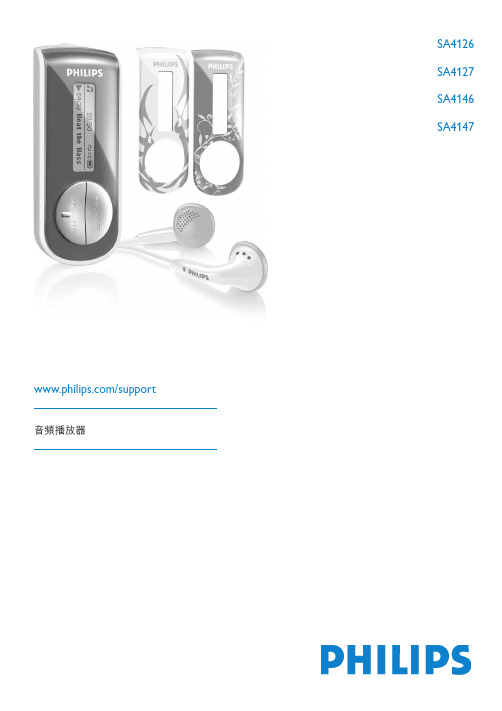
SA4126SA4127SA4146SA4147/support音頻播放器需要幫助嗎?請造訪/support您可由此獲取完整的支援資料,例如用戶手冊、最新軟體升級及常見問題解答等等。
21重要安全事項5修改72您的新播放器82.1產品內容8 2.2產品註冊8 3初次使用83.1控制鍵及連線概覽9 3.2安裝9 3.3連接10 3.3.1插入電池103.3.2閱讀播放器上的電池電力指示10 3.4傳輸10 3.5享受音樂11 3.5.1開機及關機113.5.2功能表導航11 4利用Windows Media Player 11 整理及傳輸照片和音樂114.1關於Windows Media Player 11 12 4.1.1安裝Windows Media Player 11 之前(選擇性)124.1.2安裝Windows Media Player 11 124.1.3回復舊版本的Windows Media Player 164.1.4回復舊版本Windows Media Player 的進階操作17 4.2音樂及照片傳輸17 4.2.1將音樂和照片檔加入Windows Media Player 的媒體櫃17 4.2.2在Windows Media Player 和您的播放器的音樂和照片媒體櫃之間轉換19 4.2.3從CD 擷取歌曲19 4.2.4線上購買音樂22 4.3將您的Windows Media 內容同步更新至播放器23 4.3.1設置您的播放器23 4.3.2在自動和手動同步之間轉換23 4.3.3選擇自動同步的項目及設定優先順序24 4.3.4選擇手動同步的檔案和播放清單25 4.3.5隨機選擇您的播放器上的手動同步項目26 4.3.6將播放器的檔案複製到電腦27 4.4管理您的Windows Media Player 播放清單28 4.4.1建立一個標準播放清單28 4.4.2建立一個自動播放清單29 4.4.3編輯播放清單30 4.4.4傳輸播放清單至您的播放器3134.5在Windows Media Player 內管理您的檔案和播放清單314.5.1透過Windows Media Player 搜尋音樂或照片324.5.2從Windows Media Player 媒體櫃刪除檔案和播放清單324.5.3從您的播放器刪除檔案和播放清單324.5.4添加或修改專輯封面334.5.5透過Windows Media Player 編輯歌曲資訊334.5.6透過Windows Media Player 格式化您的播放器345詳細操作說明355.1音樂模式(亦適用於播放錄音) 36控制鍵365.1.2播放功能365.2錄音375.2.1進行錄音385.2.2播放錄音385.2.3將錄音上載至電腦385.2.4刪除錄音385.3設定385.4利用您的播放器儲存及攜帶數據檔案396升級您的播放器396.1手動檢查您的套件是否為最新版本407技術數據408常見問題419詞彙表43 41一般保養避免本裝置損壞或故障:•請勿將播放器暴露在過熱的場所,例如加熱設備附近或受陽光直接照射。
IOzone使用简介(Windows 2003)
Iozone使用简介(Windows 2003)修改记录目录实战简介(单节点) (3)一、Iozone的安装: (3)二、执行测试: (4)二、测试结果收集与整理: (5)实战简介(集群测试) (6)一、Iozone的安装: (6)二、rsh配置: (6)1、主机名设置: (6)2、安装rsh:该操作需要在每个节点上进行。
(6)3、在发送指令节点(as140)上安装Cygwin: (7)4、rshd服务的配置: (9)二、Iozone集群测试: (10)三、测试结果收集与整理: (10)知识串烧 (12)一、经常用到的参数: (12)二、Iozone包含的测试种类: (12)三、资料路径: (12)实战简介(单节点)一、Iozone的安装:1、双击setup.exe进行iozone的安装,如下图安装步骤:2、安装完成后,默认安装路径下C:\Program Files\benchmarks\Iozone 3.321会生成一个iozone.exe的文件,在执行测试时需要将该文件拷贝至待测试的目录下。
二、执行测试:首先,进入DOS命令行模式(Ctrl+R—cmd—回车),进入到待测试的目录下,查看是否存在iozone.exe文件。
执行命令:iozone -az -b **** -g 4g -y 32k -i 0 -i 1说明:-az——执行不同粒度(record size)和测试文(file size)的自动化测试,默认情况下record size从4K—16M,file size从64K—512M。
-b——指定测试后生成的excel文件。
-g——指定最大的file size大小。
(一般为内存的两倍)-y——指定最小的record size数值。
-i——指定测试的种类。
(0代表write/rewrite,1代表read/re-read)下图为测试过程中屏幕显示部分信息(实际测试指令为iozone –b c:\aaa –az –g 1M –y 64K –i 0 –i 1):第一列为测试的file size;第二列为测试的record size;后四列分别对应不同测试方法的测试结果(单位为Kb/s)。
乐龙操作说明

目录第一部分基础知识 (8)第一章界面介绍 (8)1.1主界面介绍 (8)1.2菜单栏 (9)1.2.1“文件(F)” (9)1.2.2“编辑(E)” (16)1.2.2.1关于多个复制 (17)1.2.3“表示(V)” (18)1.2.4“模拟(S)” (19)1.2.5“环境(R)” (20)1.2.5.1关于环境设定的内容 (21)1.2.5.2关于颜色的设定方法 (26)1.2.5.3关于单位指定 (27)1.2.5.4关于更改最大时间间隔 (28)1.2.5.5关于光源设置 (28)1.2.6“视点(P)” (30)1.2.7“窗口(W)” (31)1.2.8“设备(D)” (32)1.2.9“作业管理器(T)”<只限于Brain> (33)1.2.10“作业管理器关联设备(M)”<只限于Brain> (33)1.2.11 “特殊设备(3)” (35)1.2.12 “工具(4)” (37)1.2.13“帮助(H)” (42)1.3工具栏 (43)1.4状态栏 (45)1.5消息栏 (45)1.6设备栏 (46)1.7视图控制栏 (50)1.8位置栏 (52)1.9时间栏 (53)1.10属性栏 (56)1.11设备库文件 (59)1.12设备检索栏 (59)1.13视点目录栏 (63)第二章基本操作 (64)2.1设备的表示 (64)2.2设备的选择 (64)2.3设备的移动 (65)2.4设备的复制&粘贴 (65)2.5多个设备的同时选择 (66)2.6设备组合 (67)2.7放大/缩小 (68)2.8画面的转动 (68)2.9画面的水平移动 (68)2.10中心点的设定 (68)2.11多个设备的同时移动 (68)2.12取消设备组合 (68)2.13设备的连接(与下一个设备相连) (68)2.14取消连接 (69)2.15货物、托盘的自动投入 (69)2.16货物、托盘的个别投放 (69)2.17设备的删除 (69)2.18搜索消失的模型 (69)2.19模拟的开始 (69)2.20模拟的停止 (69)关于模型的前后左右 (70)关于各种设备 (71)第二部分设备模块 (74)第三章关于设备的说明 (74)3.1只限于在Brain中可以使用的设备 (74)3.2通用项目 (75)3.2.1弹出菜单 (75)3.2.1.1与下一个设备相连 (75)取消连接 753.2.1.2属性 (75)3.2.1.3逆时针旋转90度 (75)3.2.1.4顺时针旋转90度 (75)3.2.1.5旋转180度 (75)3.2.1.6用鼠标旋转 (75)3.2.1.7用鼠标改变尺寸 (75)3.2.1.8删除 (76)3.2.2属性 (76)3.2.2.1概要页面 (76)3.2.2.2尺寸页面 (76)3.2.2.3色/形页面 (77)3.2.2.4图层/层面页面 (77)3.3摆设物 (78)3.3.1立方体[设备栏] (78)3.3.2球[设备栏] (78)3.3.3圆锥[设备栏] (79)3.3.4圆柱[设备栏] (79)3.3.5卡车[设备/菜单] (80)3.4通路/障碍物 (81)3.4.1障碍物[作业管理器关联设备/菜单] (81)3.4.2阶梯[作业管理器关联设备/菜单] (81)3.4.3领域设备[作业管理器关联设备/菜单] (82)3.5转车轨道、铁轨滑车、升降机 (83)3.5.1铁轨滑车[设备栏] (83)3.5.2直线转车轨道[设备栏] (84)3.5.3左曲转车轨道[设备栏] (85)3.5.4右曲转车轨道[设备栏] (85)3.5.5Y字型分流转车轨道[设备栏] (86)3.5.6右分流转车轨道[设备栏] (86)3.5.7左分流转车轨道[设备栏] (86)3.5.8三分流转车轨道[设备栏] (87)3.5.9升降机[设备/菜单] (88)3.5.10垂直搬送机[设备/菜单] (89)3.5.11超强升降机[作业管理器关联设备/菜单] (90)3.5.12吊车[作业管理器关联设备/菜单] (90)3.6传送带 (93)3.6.1直线传送带[设备栏] (93)3.6.2右折传送带[设备栏] (96)3.6.3左折传送带[设备栏] (96)3.6.4右曲传送带[设备栏] (97)3.6.5左曲传送带[设备栏] (97)3.6.6右分流传送带[设备栏] (98)3.6.7左分流传送带[设备栏] (98)3.6.8左右分流传送带[设备栏] (100)3.6.9三分流传送带[设备栏] (103)3.6.10右合流传送带[设备栏] (105)3.6.11左合流传送带[设备栏] (105)3.6.12合流传送带[设备栏] (107)3.6.13三合流传送带[设备栏] (108)3.6.14直交传送带[设备栏] (110)3.6.15直交传送带二[设备栏] (111)3.6.16组合传送带[设备栏] (112)3.6.17直线皮带型传送带[设备栏] (114)3.6.18转向台[设备栏] (114)3.6.19蓄积型传送带[设备栏] (115)3.6.20蓄积型右曲传送带[设备栏] (117)3.6.21蓄积型左曲传送带[设备栏] (117)3.6.22放机[设备/菜单] (120)3.7中转站 (121)3.7.1装货平台[设备栏] (121)3.7.2卸货平台[设备栏] (122)3.7.3货物分类系统滑捆包场所[作业管理器关联设备/菜单] (123)3.7.4多功能分流站[特殊设备/菜单] (124)3.8控制 (126)3.8.1智能导向物[设备栏] (126)3.8.2智能导向物二[设备栏] (129)3.8.3计时器[设备栏] (130)3.8.4自动立体仓库控制器[设备栏] (131)3.8.5ID管理器[设备/菜单] (131)3.8.6流量控制器[设备/菜单] (132)3.8.7车位管理设备[作业管理器/菜单] (132)3.8.8XML计划管理器[设备栏] (132)3.8.9作业要求路由器[作业管理器关联设备/菜单] (133)3.8.10货物分类系统控制器[作业管理器关联设备/菜单] (133)3.8.11货物分类系统滑梯口[作业管理器关联设备/菜单] (135)3.8.12初始库存管理器[设备栏] (136)3.8.13转车轨道控制器[特殊设备/菜单] (137)3.8.14通过切换器[特殊设备/菜单] (138)3.8.15固定点[特殊设备/菜单] (138)3.8.16整流设备[特殊设备/菜单] (139)3.8.17信息替换设备[特殊设备/菜单] (139)3.8.18分类系统控制器[特殊设备/菜单] (139)3.8.19动力控制设备[特殊设备/菜单] (140)3.9货架、仓库、放置场所 (142)3.9.1自动仓库[设备栏] (142)3.9.2货架区2[设备栏] (145)3.9.3移动货架[作业管理器关联设备/菜单] (147)3.9.4暂存区[作业管理器关联设备/菜单] (149)3.9.5摞放区[作业管理器关联设备/菜单] (153)3.9.6多功能起重机[特殊设备/菜单] (154)3.10货物、托盘等的发生、消滅 (157)3.10.1部件消灭器[设备栏] (157)3.10.2部件生成器[设备栏] (157)3.10.3托盘供应器[设备栏] (159)3.10.4周转箱生成器[设备/菜单] (160)3.10.5散货托盘生成器[设备/菜单] (161)3.10.6空箱要求[作业管理器关联设备/菜单] (162)3.10.7进货物品生成器(卡车进货)[作业管理器关联设备/菜单] (162)3.11托盘、笼车 (163)3.11.1笼车[设备栏] (163)3.11.2托盘[设备栏] (163)3.12人、机器人 (165)3.12.1智能人[设备栏] (165)3.12.2机器人二[设备栏] (166)3.12.3多关节机器人[设备/菜单] (166)3.12.4有轨机器人[设备/菜单] (167)3.13厂商的装置设备 (168)3.13.1SAS(机体)[特殊设备/菜单] (168)3.13.2SAS(保留器)[特殊设备/菜单] (170)3.14其它 (172)3.14.13D文字[特殊设备/菜单] (172)3.14.23D尺寸[特殊设备/菜单] (172)3.14.3DXF貼付[特殊设备/菜单] (173)3.14.4摄像机门框[特殊设备/菜单] (174)3.14.5加工设备[特殊设备/菜单] (176)3.15作业管理器 (177)3.15.1XML作业管理器[设备栏] (177)3.15.2通用作业管理器[作业管理器栏] (180)3.16通过弹出菜单所添加出的设备、付属的设备 (185)3.16.1平板车 (185)3.16.2垂直搬送机的输入/输出部件 (186)3.16.3输入部件 (186)3.16.4输出部件 (187)3.16.5由货架区2所添加的货架 (189)3.16.6由货架区2所添加的流动式货架 (190)3.16.7由货架区2所添加的回转式货架 (191)3.16.8由货架区2所添加的回转式货架的EDIT IN ARROW(箭头) (192)3.16.9由货架区2所添加的回转式货架的EDIT OUT ARROW(箭头) (193)3.16.10装货平台的EDIT IN ARROW(箭头) (193)3.16.11卸货平台的EDIT OUT ARROW(箭头) (193)3.16.12由摞放区所添加出的货架 (194)3.16.13货箱 (195)3.16.14托盘 (195)3.16.15自动仓库的IO部件(In Mode) (196)3.16.16自动仓库的IO部件(Out Mode) (197)3.16.17多功能起重机的IO部件(In Mode) (198)3.16.18多功能起重机的IO部件(Out Mode) (199)3.16.19铁轨滑车的IO部件(In Mode) (200)3.16.20铁轨滑车的IO部件(Out Mode) (201)3.16.21SAS机体的小机车(线性轨道) (202)3.16.22作业管理器的作业员 (203)3.16.23摄像机 (205)3.16.24挡板 (208)3.16.25传感器 (209)3.16.26通过控制接头 (209)第四章正规表达式 (211)第五章作业要求小组 (212)第六章关于所使用的数据文件的说明 (213)6.1XML数据格式 (213)6.1.1解说XML数据各项目 (213)6.1.2XML数据使用上的规则 (213)6.1.3模拟管理文件所使用的数据形式 (213)6.1.4商品管理文件中所使用的数据形式 (215)6.1.5库存、入库、出库等所使用的数据形式 (218)6.1.6初始库存数据的例子 (221)6.1.7进货数据的例 (222)6.2分类暂存区的数据文件格式 (223)6.3信息替换设备的数据文件格式 (224)6.4用于RaLC-Pro的作业指示文件的数据格式 (226)6.4.1解说作业指示文件 (226)6.4.2部件生成器及托盘供应器的生成文件 (226)6.4.3分布信息文件 (226)6.4.4生成信息文件 (227)6.4.5条形码文件 (228)6.4.6自动仓库出库文件 (229)6.4.7出库信息文件 (229)第七章设备名检索 (231)第三部分其他功能 (235)第八章录像制作 (235)8.1实时的记录方式 (236)8.2设置视点的记录方式 (237)8.3视点时间设定画面介绍 (239)8.3.1时间模式画面: (239)8.3.2时间差模式 (240)8.3.3时间设定 (240)附录:Fan模型制作 (241)第一部分 基础知识第一章 界面介绍本章内容主要对RaLC 系列软件各种操作界面上的菜单栏、工具栏和功能按钮进行详细介绍。
主面板使用手册(Ample China Zheng)说明书

主面板用户手册Ample China Zheng北京博声音元科技有限公司技术文档目录1乐器面板(INSTRUMENT PANEL) (4)1.1乐器面板概述(O VERVIEW OF I NSTRUMENT P ANEL) (4)1.2预制文件读取/保存(S AVE/L OAD P RESET) (4)1.3语言选择(英文/中文)(L ANGUAGE) (4)2主面板(MAIN PANEL) (5)2.1主面板概述(O VERVIEW OF M AIN P ANEL) (5)2.2演奏法(A RTICULATIONS) (6)2.2.1 演奏法列表(Articulation List) (6)2.2.2 长音(Sustain) (6)2.2.3 泛音(Natural Harmonic) (6)2.2.4 摇指(Tremolo) (7)2.2.5 刮奏单音(Glissando) (8)2.2.6 上花指(Glissando Up) (9)2.2.7 下花指(Glissando Down) (9)2.2.8 回滑音(Full Bend) (9)2.2.9上滑音(Bend Up) (9)2.2.10 下滑音(Bend Down) (10)2.2.11 点音(Tap) (10)2.2.12 揉弦(Vibrato) (10)2.2.13 乐句(Lick) (10)2.2.14 话筒模式(Mic Mode) (11)2.3调(K EY) (11)2.4丰富的演奏噪音(R ICH F RET N OISE) (11)2.5演奏模式(P LAY M ODES) (11)2.6推弦(B END) (12)2.7颤音(M OD W HEEL) (12)2.8效果音组(FX S OUND G ROUP) (13)2.9重复键(R EPEAT) (13)2.10延音踏板开关(H OLD P EDAL T OGGLE) (13)1乐器面板(Instrument Panel)1.1 乐器面板概述(Overview of Instrument Panel)1.2 预制文件读取/保存(Save/Load Preset)点击预置名读取预置,左右箭头快速切换预置。
乐享物理助手 用户手册
乐享物理助手——使用手册软件安装系统需求1.基本要求:适合于运行在Microsoft Windows 的各个版本下,包括Windows98、Windows Me、Windows NT、Windows2000、Windows XP、win7等平台下(Windows98、WindowsMe下如果不能正常运行,请到http://www.001help.com/ 下载“低版本Windows下的支持文件”安装后即能正常运行!).2.硬件:(1)硬件要求:奔腾400MHz或更快,64MB内存或更多,60MB磁盘剩余空间.建议:奔腾800MHz 或更快,128MB内存或更多,100Mb磁盘以上剩余空间.(2)软件要求:预安装Microsoft Word2000或以上版本3.安装:下载软件并解压缩后,运行软件中的,,按照提示操作即可。
安装完成后会在桌面或者快速启动栏出现如下快捷方式:,今后运行软件只需双击此图标。
卸载在开始菜单的乐享物理助手程序组中,单击“卸载乐享物理助手”,卸载程序将自动地删除软件。
功能介绍软件概述:本软件主要包括:快捷输入窗口、超级工具箱、超级素材库、词条库管理与添加、常用网址收藏、软件注册与购买等几个功能模块。
使用本软件可以快速键盘输入各种代数式、方程式以及分数、分式、根式、常用数学公式(包括大学中的微积分公式等),对于数字会自动设置为下标;内置数学学科各种常用基本图形、基本公式,可以快速拼装和生成复杂数学图形、公式;快速输入各种学科符号、使用数轴表示区间、小数转分数、分解质因数、计算阶乘等;初中和高中常见函数图像的定制;快速设置各种文档常用格式、快速操作图形,以及快速整理文档去除冗余内容如:清除空格、空行、空白段落、按大纲生成文档目录、分页保存文档、清除超链接,快速设置文档版式、试卷相关设置,快捷的试卷整理工具等。
另外,本软件还具有十分强大的扩展功能:一键收藏word文档中的所有图形;一键添加学科词条,自建学科词条库;精品素材整理等。
AudioCodes MediaPack 5xx 数字语音网关系列说明书
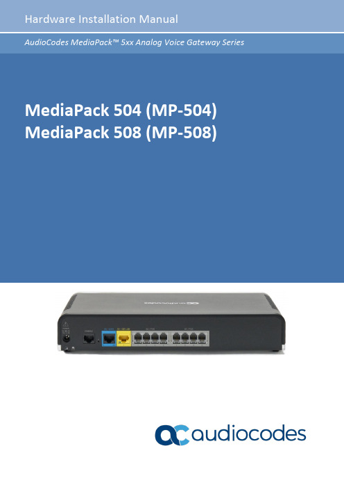
Contents MP-504/8Table of ContentsMediaPack 504-508 (MP-5xx) Hardware Installation Manual (1)Notice ............................................................................................................................... i ii WEEE EU Directive ........................................................................................................................... i ii Customer Support............................................................................................................................ i ii Stay in the Loop with AudioCodes ................................................................................................... i ii Abbreviations and Terminology ...................................................................................................... i ii General Notes and Warnings ........................................................................................................... i ii Safety Precautions ........................................................................................................................... i v Related Documentation ................................................................................................................... i v Documentation Feedback ................................................................................................................ i v 1Introduction . (5)2Unpacking the Device (6)3Physical Description (7)3.1Physical Dimensions and Operating Environment (7)3.2Front Panel Description (7)3.3Rear Panel Description (8)4Mounting the Device (9)4.1Desktop mounting (9)4.219-Inch Rack Mounting (9)4.3Wall Mounting (12)5Cabling the Device (14)5.1Cabling WAN Interface (14)5.2Cabling FXS Analog Interfaces (15)5.3Connecting to Power (17)WEEE EU DirectivePursuant to the WEEE EU Directive, electronic and electrical waste must not be disposed of withunsorted waste. Please contact your local recycling authority for disposal of this product.Customer SupportCustomer technical support and services are provided by AudioCodes or by an authorizedAudioCodes Service Partner. For more information on how to buy technical support for AudioCodesproducts and for contact information, please visit our website athttps:///services-support/maintenance-and-support.Stay in the Loop with AudioCodesAbbreviations and TerminologyEach abbreviation, unless widely used, is spelled out in full when first used.Throughout this manual, unless otherwise specified, the term device refers to the MediaPack 504 /508 (MP-504/MP-508) analog voice gateway.General Notes and WarningsWarning: The device must be installed only indoors.Open-source software may have been added and/or amended. For further information, contact your AudioCodes sales representative.Safety Precautions◼It's recommended that Ethernet and phone (FXS) cabling be routed only indoors and not exit the building.◼Do not open or dismantle the device.◼Do not expose the device to water or moisture.◼Make sure the device is installed in a well-ventilated location to avoid overheating of internal components and subsequent damage.◼Do not place any object on top of the device and make sure that sufficient clearance from the top and sides are maintained to ensure proper airflow to avoid over heating of internalcomponents.◼Operate the device in an ambient temperature (Tma) that does not exceed 40°C (104°F).◼Use only the supplied AC/DC power adapter for connection to the power source.Warning: In case of a malfunction, do not attempt to fix the power adapter and do not useany other type of power adapter.Related DocumentationDocumentation FeedbackAudioCodes continually strives to produce high quality documentation. If you have any comments(suggestions or errors) regarding this document, please fill out the Documentation Feedback form onour website at https:///documentation-feedback.1. Introduction MP-504/81IntroductionThis document provides a hardware description of the device and step-by-step procedures formounting and cabling the device.The device supports the following interfaces:◼WAN interface - single Gigabit Ethernet copper (10/100/1000Base-T)◼LAN interface - single Gigabit Ethernet (1000Base-T) LAN port (RJ-45)◼Telephony interfaces:•MP-504 model: One slot of four FXS port interfaces•MP-508 model: Two slots, each providing four FXS port interfaces (i.e., total eightinterfaces)◼Serial console port (RJ-45) for device management2. Unpacking the Device MP-504/82Unpacking the DeviceFollow the procedure below for unpacking the carton in which the device was shipped.To unpack the device:1.Open the carton and carefully remove packing materials.2.Remove the chassis from the carton.3.Check that there is no equipment damage.4.Ensure that in addition to the chassis, the package contains the following items:•Four anti-slide bumpers for desktop installation•AC/DC power adapter3Physical DescriptionThis section provides a physical description of the device.3.1Physical Dimensions and Operating EnvironmentThe device's physical dimensions and operating environment are listed in the table below:Table 1: Physical Dimensions and Operating EnvironmentSpecificationValueDimensions (H x W x D) 51 x 296 x 165 mm (2 x 11.65 x 6.5 in.) Weight670 g (1.5 lbs.)Operating Environment◼Operational: 5 to 40°C (41 to 104°F) ◼ Storage: -25 to 85°C (-13 to 185°F)◼ Relative Humidity: 10 to 90% non-condensing3.2 Front Panel DescriptionThe front panel provides LEDs for indicating the status of various functionalities. The LEDs are shown in the figure below and described in the subsequent tables.Figure 1: Front Panel1PowerLED indicating power status: Green On Power received by device. OffNo power.2 Status LED indicating operating status: Green On Device is operational.Green Flashing Initial rebooting stage or software upgrade in process. Red OnBoot failure.3 WAN GE LED indicating Gigabit Ethernet WAN link status: Green On WAN GE link established. Green Flashing Data received or transmitted.OffNo WAN GE link or power not received by the device.1233.3 Rear Panel DescriptionThe device's rear panel is shown in the figure below and described in the subsequent table.Figure 2: Rear Panel1 POWER DC power plug entry for external AC/DC power adapter.2//Reset pinhole button for resetting the device or restoring it to factory defaults. To restore to factory defaults: with a paper clip or any other similar pointed object, press and hold down the button for at least 12 seconds (but no more than 25 seconds). Please note that the device will lose all its configuration!3 S0 / WANWAN interface port Giga Ethernet (10/100/1000Base-T) Green On Ethernet link established. Green Flashing Data is received or transmitted. OffNo Ethernet link.4S2 / FXS S3 / FXSS2: FXS ports 1-4S3: FXS ports 5-8 (applicable only to MP-508)1 2344Mounting the DeviceYou can mount the device using one of the following methods:◼Desktop mounting◼19-inch Rack mounting◼Wall mounting4.1Desktop mountingPlace the device on a desktop using the four anti-slide bumpers (supplied), which you need to stickon the grooves located on the underside of the device. The bumpers avoid involuntary movementof the unit on the desktop as well as enable better air flow for cooling the device.4.219-Inch Rack MountingYou can mount the device in a standard 19-inch rack, using AudioCodes 1U 19-inch rack mount shelf(not supplied).The AudioCodes 1U 19-inch rack mount shelf is not supplied with your product and can beordered separately from an AudioCodes sales distributor.Warning:◼Elevated Operating Ambient: If installed in a closed or multi-unit rack assembly, consideration should be given to installing the equipment in an environmentcompatible with the maximum ambient temperature (Tmax) of 40°C (104°F).◼Reduced Air Flow: Installation should be such that the amount of air flow required for safe operation on the equipment is not compromised. Do not stack equipment one on top of the other and keep the ventilation openings free from cables or any objects to allow free air circulation. The device must be mounted correctly on the rack mount shelf to avoid air blockage to the three vents located on the bottom of the device.Mounting the device on a shelf other than AudioCodes' rack mount shelf may cause the device to overheat, resulting in permanent damage to it.◼Only one device can be mounted per rack mount shelf.◼The minimum vertical rack space for mounting the device in a 19-inch rack must be 2Us (3.5 in. or 88.9 mm). See figure below.Figure 3: Minimum Vertical Space for 19-inch Rack MountingTo mount the device in a 19-inch rack:1.Position the rack mount shelf (ordered separately from AudioCodes) in the 19-inch rack,aligning the holes of the shelf's side brackets with the holes of the rack's front posts, as shown in the figure below.Figure 4: Positioning Shelf in RackMake sure that you attach the shelf's side brackets (left and right) at the same height levelin the rack so that the shelf is in a horizontal position.2.Attach the shelf to the rack posts using four standard 19-inch rack bolts (not supplied).3.Place the device on the shelf so that the device's front panel faces the front of the rack andthe device's four anti-slide rubber legs (located on the bottom of the device) fit into the four square openings on the shelf, as shown in the figure below (viewed from underneath):Figure 5: Positioning the Device's Anti-Slide Rubber Legs into Shelf's Openings4.Make sure the device is firmly mounted on the shelf so it does not horizontally slide in anydirection:Figure 6: Device Mounted on Shelf in 19-inch Rack4.3 Wall MountingYou can mount the device on a wall using the keyholes on the bottom of the device. To mount the device on a wall: 1.Drill three holes in the wall where you want to mount the device, using the distances between the holes as shown in the figure below: • Horizontal distance between the top two parallel holes: 89 mm (5.51 in.)• Vertical distance between the top two parallel holes and bottom hole: 204 mm (8.03 in.) •Horizontal distance between a top hole and the bottom hole: 44.5 (1.75 in.)Figure 7: Dimensions for Drilled Holes◼When choosing the area on the wall to mount the device, make sure that sufficient space is available for attaching cables on the rear panel.◼ Make sure that you drill the holes in the same orientation as shown in the above figure (i.e., two parallel holes on the top and the single hole on the bottom).2. Insert wall anchors of the appropriate size into each hole.3.Thread screws (not supplied) into each of the wall anchors. The recommended screw type is DIN 7982 3.5x25 Phillips flat head. Make sure that the heads extend sufficiently (about 4 mm or 0.157 in.) from the wall for the device's keyholes to hang on:Figure 8: Protruded Screw Distance from Wall Surface4.Hold the device so that it is orientated with the bottom panel with the keyholes facing thewall and the rear panel with the ports facing your right.5.Mount the device on the wall by hanging the device's keyholes on the screw heads:Figure 9: Hanging Device on Screw Heads5Cabling the DeviceThis chapter describes device cabling.Figure 10: Cabling Overview5.1Cabling WAN InterfaceThe device provides a copper Gigabit Ethernet (GbE) port interface for connecting to the WAN.Cable specification:◼Cable: straight-through Cat 5 cable◼Connector: RJ-45◼Connector Pinouts:Table 2: RJ-45 Connector Pinouts for Copper GbE WANTo connect the copper GbE WAN port:1.Connect one end of a straight-through RJ-45 Ethernet cable to the Blue RJ-45 port labeled S0 /WAN GE (located on the rear panel).Figure 11: Cabling the WAN Copper GbE Port2.Connect the other end of the cable to the WAN network (e.g., ADSL or Cable modem).5.2Cabling FXS Analog InterfacesThe procedure below describes how to cable the device's FXS interfaces. FXS is the interface replacingPrivate Branch Exchange (PBX)—and connects to analog telephones, dial-up modems, and faxmachines. The FXS is designed to supply line voltage and ringing current to these telephone devices.Warnings:◼The device must be installed and located only indoors.◼Connect the FXS ports only to certified phone devices; otherwise, damage to the device may occur.◼Keep phone (FXS) cabling routed only within the building away from any power cabling.◼Routing FXS wiring outside the building may damage the port due to surge phenomena.◼The FXS ports are considered ES2 (TNV-2); avoid contact with any exposed wiring.Cable specification:◼Cable: Standard straight-through RJ-11 telephony cable◼Connector: RJ-11◼Connector Pinouts:Figure 12: RJ-11 Connector Pinouts for FXS InterfacesTo connect an FXS interface:1.Connect one end of an RJ-11 cable to an FXS port, located on the rear panel and labeled FXS.Figure 13: Cabling FXS Interfaces2.Connect the other end of the cable to the required telephone interface (e.g., fax machine,dial-up modem, or analog POTS telephone).5.3Connecting to PowerThe device is powered by an external 12V AC/DC power adapter (supplied), connected to a standardalternating current (AC) electrical wall outlet.Table 3: Power SpecificationsWarning: Use only the AC/DC power adapter supplied with the device.Warning: Do not open or service the AC/DC power adapter. If it's broken, do not use it anddo not plug it into the electrical wall socket; contact AudioCodes for a Return MaterialAuthorization (RMA).Notice: for PLUGGABLE EQUIPMENT, the socket-outlet shall be installed near theequipment and shall be easily accessibleThe device is shipped with the 3A AC/DC power adapter shown in the figure below. The power adapter also supports interchangeable plugs to suit the electrical wall outlet type requirement of the country in which the device is being installed.Figure 14: 3A AC/DC Power AdapterTable 4: Power Adapter with Interchangeable PlugsTo connect the device to the power supply using the 3-Amp power adapter:1.Insert the relevant AC plug into the housing power adapter:a.Insert the top part of the plug into the upper part of the housing slot (1).b.Press down on the bottom part of the plug until a "click" sound is heard, indicating thatthe plug is securely inserted in the housing slot. To remove the plug, push and slide downthe OPEN plug release lever (3).Figure 15: Inserting Plug into Power Adapter2.Insert the DC plug (5) located at the end of the power cord (4) of the power adapter into thedevice's power socket located on the rear panel.Figure 16: Cabling to Power with 3A AC/DC Power Adapter3.Plug the power adapter directly into a standard electrical wall outlet.4.the plug at the other end of the AC power cord to a standard electrical outlet.International Headquarters1 Hayarden Street,Airport CityLod 7019900, IsraelTel: +972-3-976-4000Fax: +972-3-976-4040AudioCodes Inc.80 Kingsbridge RdPiscataway, NJ 08854, USATel: +1-732-469-0880Fax: +1-732-469-2298Contact us: https:///corporate/offices-worldwideWebsite: https://Documentation feedback: https:///documentation-feedback©2023 AudioCodes Ltd. All rights reserved. AudioCodes, AC, HD VoIP, HD VoIP Sounds Better, IPmedia, Mediant, MediaPack, What’s Inside Matters, OSN, SmartTAP, User Management Pack, VMAS, VoIPerfect, VoIPerfectHD, Your Gateway To VoIP, 3GX, VocaNom, AudioCodes One Voice, AudioCodes Meeting Insights, and AudioCodes Room Experience are trademarks or registered trademarks of AudioCodes Limited. All other products or trademarks are property of their respective owners. Product specifications are subject to change without notice.Document #: LTRT-10613。
ControlCenter Zone Controllers 使用说明书
CC-1CC-2CC-3ControlCenterZone ControllersInstallation and Operation Guide Guía de Instalación y Funcionamiento Guide d’installation et utilisation Installations- und Bedienungsanleitung Manuale di installazione e funzionamento Installatie- en bedieningshandleidingPlease read this owner’s guide carefully and save it for future reference.1. Read these instructions.2. Keep these instructions.3. Heed all warnings.4. Follow all instructions.5. Do not use this apparatus near water.6. Clean only with a dry cloth.7. Do not block any ventilation openings. Install in accordance with the manufacturer’s instructions.8. Do not install near any heat sources, such as radiators, heat registers, stoves or other apparatus (including amplifiers) that produce heat.9. Only use attachments/accessories specified by the manufacturer.10.Refer all servicing to qualified personnel. Servicing is required when the apparatus has been damaged in any way, such as power-supply cord or plug is damaged, liquid has been spilled or objects have fallen into theapparatus, the apparatus has been exposed to rain or moisture, does not operate normally, or has been dropped.WARNING:• All Bose products must be installed in accordance with local, state, federal and industry regulations. It is the installer’s responsibility to ensure installation of the loudspeakers and mounting system is performed in accordance with all applicable codes, including local building codes and regulations. Consult the local authority having jurisdiction before installing this product.• T o reduce the risk of fire or electrical shock, do not expose the product to rain or moisture.• Do not expose this apparatus to dripping or splashing, and do not place objects filled with liquids such as vases, on or near the apparatus. Exposure to liquid may create a fire hazard.• Do not place any naked flame sources, such as lighted candles, on or near the apparatus.•This product is not intended for installation or use in indoor water facility areas (including, withoutlimitation, indoor pools, indoor water parks, hot tub rooms, saunas, steam rooms and indoor skating rinks).Contains small parts which may be a choking hazard. Not suitable for children under age 3.CAUTION:•Do not make unauthorized alterations to the product; doing so may compromise safety, regulatory compliance, system performance, and may void the warranty.This product is intended for installation by professional installers only! This document is intended to provideprofessional installers with basic installation and safety guidelines for this product in typical fixed-installation systems.Please read this document before attempting installation.This product conforms to all applicable EU directive requirements. The complete Declaration of Conformity can be found at /complianceImportant Safety Instructions2 EnglishThe exclamation point within an equilateral triangle, as marked on the system, is intended to alert the user tothe presence of important operating and maintenance instructions in this installation guide.Product FeaturesBose® ControlCenter zone controllers provide three options for remote volume control and input source selection:Controller Function Compatible ProductsCC-1Volume control only FreeSpace® IZA 2120-LZ/HZFreeSpace ZA 2120-LZ/HZPowerShare PS602 & PS604Any ControlSpace® engineered sound processorCC-2Volume control with A/Bsource selection switch FreeSpace IZA 250-LZ; IZA 190-HZ FreeSpace IZA 2120-LZ/HZAny ControlSpace engineered sound processorCC-3Volume control with A/B/C/Dsource selection switchAny ControlSpace engineered sound processorEach zone controller is available in white and black, and in North America, Japan, and EU configurations. The North America zone controllers are sized for Decora® wall mounting, and include two 1/2 inch #6-32 screws. The Japan zone controllers fit Wide 21 wall plates with aface height of 1 mm above the thick wall plate cover; the controllers have approximately 3 mm face height when used with other types of wall plate covers. Two 8 mm M4 screws are included. Wall plate covers are not included with North America and Japan zone controllers. The EU zone controllers come as a finished wall plate of size 86 mm x 86 mm, with 60 to 60.3 mm screw spacing suitable for either vertical or horizontal mounting, and include two 18 mm M4 screws. All models include a sheet of pre-printed color-matched labels, plus two blank labels for customized applications.Connecting a Single Zone ControllerConnect a single zone controller to a FreeSpace or PowerShare amplifier using a CAT 5 cable with maximum length of 609 meters (2000 feet). Connect to a ControlSpace ESP using a CAT5 cable with a maximum length of 152 meters (500 feet) for a shielded cable or 30 meters (100 feet) for an unshielded cable.The cable must be terminated on one end with an RJ-45 connection using TIA/EIA 568B pinout, and on the other end with an RJ-45 connector for PowerShare amplifiers, or the Euroblock connector appropriate for the FreeSpace amplifier or ControlSpace engineered sound processor (2-pin, 4-pin, or 6-pin).Introduction 8 English Introduction Connecting Multiple Zone ControllersSome amplifier models allow adjacent zone controllers to be ganged together directly. Each zone controller can be independently configured to control any output, or combination of outputs, for bi-amping.Use a CAT 5 cable with RJ-45 connectors to connect zone controllers to each other, then create a single home run from the last zone controller in the chain back to the amplifier. The maximum total cable length (from the first zone conroller to the amplifier) is 609 meters (2000 feet). Use standard CAT 5 cables and RJ-45 connectors as described in Connecting a Single Controller. CV41 4-to-1 ConverterFor PowerShare amplifier models, you can use the CV41 4-to-1 Converter to create a single home run back to an amplifier from multiple zone controllers distributed throughout an installation. Connect each zone controller to the CV41 converter using CAT 5 cables with RJ-45 connectors, then run a single CAT 5 cable from the CV41 4-to-1 Converter to the amplifier. You can connect up to two CC-1 zone controllers to a PS602 amplifier, and up to four CC-1 zone controllers to a PS604 amplifier.English 9CC-1 Zone Controller - North AmericaCC-1 Zone ControllerThe CC-1 zone controller provides volume control only. It is compatible with FreeSpace® IZA 2120-LZ/HZ and ZA 2120-LZ/HZ amplifiers, PowerShare PS602 and PS604 amplifiers, and any ControlSpace® engineered sound processor (ESP).CC-1 Installation Guide CC-1 Zone Controller - Japan10 EnglishCC-1 Installation GuidePin-to-Remote ConnectionsConnections from the RJ-45 (TIA/EIA 568B wiring) connector on the CC-1 zone controller to the REMOTE connector on the FreeSpace® amplifier or CONTROL INPUTS connector on theControlSpace® engineered sound processor (ESP).CC-1 Zone Controller - EURear ViewEnglish 11Connecting the CC-1 Zone ControllerConnect one CC-1 zone controller to FreeSpace® amplifier models IZA 2120-LZ/HZ or ZA 2120-LZ/HZ, PowerShare amplifier models PS602 or PS604, or any ControlSpace® engineered sound processor (ESP).FreeSpace ZA 2120-LZ/HZEither RJ-45 on CC-1 Zone ControllerFreeSpace IZA 2120-LZ/HZEither RJ-45 on CC-1 Zone ControllerControllerCAT 5 cable Use either RJ-45connectionCC-1 Installation Guide12 EnglishPin-to-Remote Connection DiagramsAny ControlSpace ESPEither RJ-45 on CC-1 Zone ControllerCC-1 Installation GuideEnglish 13Configure the CC-1 zone controller using the following DIP switch settings:12345678FreeSpace 00101000PowerShare*0010****ControlSpace11* For the PowerShare PS602 and PS604 amplifiers, the CC-1 controls any outputs with corresponding DIP switches in the ON position: DIP 5 - OUTPUT 1 DIP 6 - OUTPUT 2DIP 7 - OUTPUT 3 (PS604 only) DIP 8 - OUTPUT 4 (PS604 only)CC-1 Installation Guide14 EnglishConnect two ganged CC-1 zone controllers to FreeSpace® amplifier models IZA 2120-HZ or ZA 2120-HZ, or PowerShare amplifier models PS602 or PS604.CC-1 Zone Controller #2CC-1 Zone Controller #1RJ-45 #1 (Main) on CC-1 Zone Controller #2FreeSpace IZA 2120-HZRJ-45 #1 (Main) on CC-1 Zone Controller #2FreeSpace ZA 2120-HZPin-to-Remote Connection DiagramsCC-1 Installation GuideEnglish 15Configure the CC-1 zone controllers using the following DIP switch settings:12345678FreeSpaceController #100101000Controller #200010100PowerShare*Controller #10010****Controller #21***** For the PowerShare PS602 and PS604 amplifiers, the CC-1 controls any outputs with corresponding DIP switches in the ON position: DIP 5 - OUTPUT 1 DIP 6 - OUTPUT 2DIP 7 - OUTPUT 3 (PS604 only)DIP 8 - OUTPUT 4 (PS604 only)CC-1 Zone Controller #1CC-1 Zone Controller #2PowerShare AmplifiersFreeSpace AmplifiersCC-1 Zone Controller #1CC-1 Zone Controller #216 EnglishConnect up to four ganged CC-1 zone controllers to the PowerShare amplifier model PS604.CC-1 Zone Controller #4CC-1 Zone Controller #3CC-1 Zone Controller #2CC-1 Zone Controller #1Configure the CC-1 zone controllers using the following DIP switch settings:12345678Controller #100101000Controller #200100100Controller #300100010Controller #411CC-1 Zone Controller #1CC-1 Zone Controller #3CC-1 Zone Controller #4CC-1 Zone Controller #2Connect multiple CC-1 zone controllers to PowerShare amplifier models PS602 or PS604 using the CV41 4-to-1 converter. Connect up to two CC-1 zone controllers to the PS602 amplifier or up to four CC-1 zone controllers to the PS604 amplifier.English 17CC-1 Zone Controller #1CC-1 Zone Controller #2Configure the CC-1 zone controllers using the following DIP switch settings:12345678Controller #100101000Controller #21118 EnglishConfigure the CC-1 zone controllers using the following DIP switch settings:12345678Controller #100101000Controller #200100100Controller #300100010Controller #411CC-1 Zone Controller #1CC-1 Zone Controller #3CC-1 Zone Controller #4CC-1 Zone Controller #2Connect up to four CC-1 zone controllers to the PowerShare PS604 amplifier using the CV41 4-to-1 converter.CC-2 Zone ControllerThe CC-2 zone controller provides volume control and A/B source selection. It is compatible with FreeSpace® amplifier models IZA 250-LZ, IZA 190-HZ, and IZA 2120-LZ/HZ, and any ControlSpace® engineered sound processor (ESP).English 19CC-2 Zone Controller - JapanCC-2 Zone Controller - North America20 EnglishPin-to-Remote ConnectionsConnections from the RJ-45 (TIA/EIA 568B wiring) connector on the CC-2 zone controller to REMOTE connector on the FreeSpace® amplifier or to CONTROL INPUTS connector on theControlSpace® engineered sound processor (ESP).CC-2 Zone Controller - EURear ViewConnecting the CC-2 Zone ControllerConnect one CC-2 zone controller to FreeSpace® amplifier models IZA 250-LZ, IZA 190-HZ, and IZA 2120-LZ/HZ, and any ControlSpace® engineered sound processor (ESP).Either RJ-45 on CC-2 Zone ControllerAny FreeSpace IZAEnglish 2112345678Controller111CC-2 Zone ControllerConfigure one CC-2 zone controller using the following DIP switch settings:Pin-to-Remote Connection DiagramsAny ControlSpace ESPEither RJ-45 on CC-2 Zone Controller22 EnglishSwitch 12345678Controller #110101000Controller #2111Connect two ganged CC-2 zone controllers to FreeSpace® amplifier model IZA 2120-HZ.CC-2 Zone Controller #1CC-2 Zone Controller #2RJ-45 #1 (Main) on CC-2 Zone Controller #2FreeSpace IZA 2120-HZCC-2 Zone Controller #1CC-2 Zone Controller #2Configure two ganged CC-2 zone controllers using the following DIP switch settings:Pin-to-Remote Connection DiagramsCC-3 Zone ControllerThe CC-3 zone controller provides volume control and A/B/C/D source selection. It is compatible with any ControlSpace® engineered sound processor (ESP).English 23CC-3 Zone Controller - JapanCC-3 Zone Controller - North America24 EnglishPin-to-Remote ConnectionsConnections from the RJ-45 (TIA/EIA 568B wiring) connector on the CC-3 zone controller to theCONTROL INPUTS connector on the ESP.CC-3 Zone Controller - EURear ViewConnecting the CC-3 Zone ControllerConnect one CC-3 zone controller to any ControlSpace® engineered sound processor (ESP).Any ControlSpace ESPRJ-45 on CC-3English 25Any ControlSpace ESP152 m (500 ft) max length CAT 5 shielded cable 30 m (100 ft) max length unshielded CAT 5 cableT erminated with RJ-45 (TIA/EIA 568 pinout) on one end and 6-pin phoenix on the other endPin-to-Remote Connection DiagramsCC-3 Installation Guide 26 EnglishLimited WarrantyYour product is covered by a limited warranty, Visit for warranty details.The warranty information provided with this product does not apply in Australian and New Zealand. See our website at /au/warranty or /nz/warranty for details of the Australian and New Zealand warranty.Decora® is a registered trademark of Leviton Manufacturing Co., Inc.Importer InformationEuropean UnionBose GP, Castleblayney Road, Carrickmacross, County Monaghan, IrelandChinaBose Electronics (Shanghai) Company Limited, Part C, Plan 9, No. 353 North Riying Road, China (Shanghai) Pilot Free Trade ZoneTaiwanBose T aiwan Branch, 9F-A1, No. 10, Section 3, Minsheng East Road, T aipei City 104, T aiwan MexicoBose de México, S. de R.L. de C.V ., Paseo de las Palmas 405-204, Lomas de Chapultepec, 11000 México, D.F.CC-3 Installation GuideEnglish 27Visit us on the web at .Americas(USA, Canada, Mexico, Central America, South America) Bose Corporation The MountainFramingham, MA 01701 USACorporate Center: 508-879-7330 Americas Professional Systems, T echnical Support: 800-994-2673 AustraliaBose Pty LimitedUnit 3/2 Holker StreetNewington NSW Australia TEL 61 2 8737 9999 BelgiumBose N.V . / S.ALimesweg 2, 03700 T ongeren, Belgium TEL (32) 012-390800ChinaBose Electronics (Shanghai) Co Ltd 36F, West Gate T ower 1038 West Nanjing RoadShanghai, P.R.C. 200041 China TEL 86 21 6271 3800FranceBose S.A.S12 rue de T emara78100 St. Germain en Laye, France TEL 01-30-61-63-63Germany Bose GmbHMax-Planck Strasse 36D 61381 Friedrichsdorf, Deutschland TEL 06172-7104-0Hong Kong Bose LimitedSuites 2101-2105, T ower One, Times Square 1 Matheson Street, Causeway Bay, Hong Kong TEL 852 2123 9000IndiaBose Corporation India Private Limited Salcon Aurum, 3rd FloorPlot No. 4, Jasola District Centre New Delhi – 110025, India TEL 91 11 43080200ItalyBose SpACentro Leoni A – Via G. Spadolini 5 20122 Milano, Italy TEL 39-02-36704500JapanBose Kabushiki Kaisha Shibuya YT Building 28-3 Maruyama-shoShibuya-Ku, T okyo, 150, Japan TEL 81-3-5489-0955 www.bose.co.jpThe Netherlands Bose BVNijverheidstraat 8 1135 GE Edam, NederlandTEL 31 (0)299-390139United Kingdom Bose HouseQuayside Chatham MaritimeChatham, Kent ME4 4QZ, United Kingdom TEL 44 (0)3330-142545See website for other countriesContact Information©2016 Bose Corporation, The Mountain, Framingham, MA 01701-9168 USAAM771705 Rev. 00。
ZoneFlex AP 内部区域挂架安装指南说明书

ZF 7731
• Neigungswinkel von 0–30° einstellbar; ideal zur Point-to-PointAP-Ausrichtung
902-0158-0000
• Zur Montage an T-Balken (Breite 2,4 cm) in abgehängten Decken; auch für versenkte T-Balken in abgehängten Decken geeignet
• Aufschraubbares Befestigungselement, somit kein Umbau der T-Balken oder Platten erforderlich
AP ZF 7762 ZF 7762-S ZF 7762-T ZF 7762-AC ZF 7762-S-AC
902-0182-0003
Hinweis: Die Stahlklemmen im Satz eignen sich für die Montage an Masten mit 2,5–6,5 cm Durchmesser. Bei einem Mastdurchmesser von mehr als 6,5 cm sind größere Klemmen erforderlich.
• Zur Montage an T-Balken (Breite 2,4 cm) in abgehängten Decken; NICHT für versenkte T-Balken in abgehängten Decken geeignet
背景音乐使用说明书

背景音乐系统使用手册太极计算机股份有限公司2013.12操作说明1、软件说明1.0 安装说明1.1 操作说明1.1.0主界面的操作1.1.1、“属性设置”窗口操作1.1.2、“分组配置”窗口操作1.1.3、“编辑程序”窗口操作1.1.4、“设备操作”窗口操作1.1.5、“PC操作”窗口操作1、软件使用操作说明1.0安装说明该软件的安装非常简单,和其它的软件安装一样。
把软件安装光盘(CD-ROM)放入光驱,打开光盘,光盘上有三个目录,分别为:WIN98、WIN2000、WINXP。
根据目前计算机的操作系统,选择相应的目录,然后点击“SETUP.EXE”文件,安装软件自动运行,点击“下一步”,直到完成。
1.1操作说明软件操作分主界面的操作、属性设置、分组配置、编辑程序、设备操作、PC操作、同步时间、帮助等八部分介绍。
1.1.0主界面的操作如下图所示,整个界面分五部分。
1、Pc播放状态显示当前计算机(PC)手动或自动播放播放状态、播放进度、播放硬盘的文件。
2、报警方式显示消防报警的方式N±0、N±1、N±2、N±3、N±4、全区报警。
旁边的绿灯表示正常状态,红灯则表示有消防报警。
报警方式的设置在“属性设置”窗口,设置完以后保存,重新启动软件。
再通过“同步时间”按键,下载至主机。
主机断电后会自动保存该数据。
3、数据接收显示主机上传的部分数据,可用于判断主机与PC通讯是否正常。
4、分控呼叫站显示该系统接入的呼叫站,绿灯为呼叫站接入该系统,目前定义可接入8台(可扩展)。
5、电源状态显示内置电源的状态,共4路。
6、在线终端-------自动统计在线终端的数量。
离线终端地址号-------自动统计显示离线终端的地址号。
注:离线的终端不能接收主机控制,可能会有声音输出。
7、上面的部分是工具栏按钮。
其中包括属性设置、分组配置、编辑程序、设备操作、PC操作、同步操作、帮助、退出系统等八部分。
Outer Space音频插件用户指南说明书
MAC OS • Double click on the DMG archive to extract it • Right click on the PKG installer and click open • Follow the instructions to install the plug-in(s)
OUTER SPACE
USER GUIDE
v1.2.1
OUTER SPACE....................................................................... 3 INSTALLATION..................................................................................................3 REGISTRATION..................................................................................................4
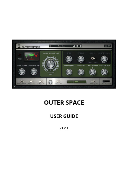
Repeat Rate Intensity WOW/Flutter Echo Volume
Controls the rate of the echo signal, emulating the changes in speed of the tape.
Controls the amount of feedback, increasing the amount of repetitions in the echo signal.
Controls the volume of the output signal.
联想LeZone操作手册
目录1.安装LeZone (2)2.安装驱动 (4)3.使用LeZone (5)3.1 LeZone与乐pad配对 (5)3.2 向乐pad添加音乐 (7)3.3 向乐pad添加视频 (8)3.4 向乐pad添加照片 (9)3.5 向乐pad添加电子书 (10)3.6 向乐pad添加office文档 (11)3.7 如何删除乐pad 中的文件 (12)4. 如何设置LeZone (13)5.使用樂Trace (14)1.安装LeZone点击安装程序包,出现“欢迎使用樂Zone安装向导”。
点击下一步,出现“许可协议”,选中,之后“下一步”按钮由灰色变为高亮,然后点击下一步选择安装路径,进行安装。
如下:最后点击安装按钮,开始安装:安装完成:重要提示:Windows XP用户需要先下载安装.net framework 3.5 SP1注意事项:1)如果在安装过程中,防火墙或杀毒软件弹出“LeZoneSrv.exe”和“ Hybrid.exe”的提醒,请允许以上程序的运行或网络访问2)如果在安装过程中,PC提示“发现新硬件”,请按照提示完成硬件驱动的安装2.安装驱动使用数据线将乐PAD与计算机连接。
系统会提示正在安装驱动:驱动安装完成后,LeZone将显示您的乐pad 设备,如下:提示:如果乐Zone安装后仍提示驱动问题,请下载驱动手动安装。
3.使用LeZone3.1 LeZone与乐pad配对使用LeZone与您的乐pad进行数据交互之前,需要先进行配对操作:配对成功后,左边栏将显示已完成配对的乐pad配对成功后,就可以开始使用LeZone 与乐pad 进行数据交互移除配对如果您的乐Pad已经配对,将进行如下操作,实现移除配对功能。
点击“配对”标签页或者樂Pad信息旁边的“更改配对”按钮,如下所示,点击“移除配对”按钮。
3.2 向乐pad添加音乐在樂Zone的主界面中,选择“添加文件”按钮,在计算机上找到您想添加的文件或文件夹,然后选择相应文件。
联想 乐pad S1常见问题

1、为什么乐Pad安装的第三方软件可能出现图标大小和自带的不一样?如果安装的第三方软件图标大小小于100*100,就可能出现小于自带图标的现象。
2、为什么光线感应作用不太明显?光线感应由亮变暗需30s,由暗变亮需4s左右;请用户耐心等待光线感应器起作用。
3、乐Pad出现“死机”故障,按开关机键或触摸无响应时,如何处理?当出现死机时,长按电源开关机键6秒,强制机器关机重启,不要做拔电池的操作4、乐PAD已连接过AP后又断开且一直无法自动重连上1. 在Pad 设置--无线网络设置中重新点击要连接的网络,连接至网络;2. 开关Pad的无线局域网设置项一次。
5、乐PAD已连接AP,为什么无法访问网络?1. AP本身是否能够访问Internet;2. 有的网络接入可能需要PPPoE拨号端或我的E家应用程序(均为PC客户端);3. 有的小区宽带可能仅限定一台终端接入,如设置Mac绑定等;4. 在麦当劳、机场等场景,访问网页需要获取额外的用户名或鉴权码之类。
6、为什么乐PAD连接不上AP?1. 连接AP时密码是否正确(如密码错误会显示为“已停用”);2. AP信号是否太弱(某些杂牌AP显示一格信号时可能7、乐Pad在Launcher界面最多支持几屏软件?最多支持9屏应用软件安装8、乐Pad设置无线局域网连接时一直显示通过网络进行身份认证,为什么?需要确认连接无线网络,是否有安全保护,如果是,需要输入正确的密码才能连接,如果密码输入不正确,有可能停在网络认证这里。
9、乐Pad可以根据重力感应调整方向,调整方向后OFN还可以用吗?乐Pad根据重力感应调整方向,旋转乐Pad向下,使OFN键位于左侧,可以很好的时候喜欢左手的用户使用pad,提示,OFN键的手势也会随之进行调整。
10、乐Pad刚开机时触摸屏操作反应缓慢是正常吗?这样是正常的,开机时由于初始化工作较多,需要加载程序,触摸反应可能较缓慢,稍微等待会恢复正常。
迪丽热巴 V2.1 快速安装指南说明书
m Quick Installation Guide (V2.1)Important InformationD e f a u l t I P:192.168.1.1(R o u t e r M o d e)192.168.1.254(A P M o d e)192.168.1.254(W i F i A P M o d e)D e f a u l t Username a d m i nD e f a u l t P a s s w o r d a d m i n※Press the Reset button to set the router back to factory settings while forgetting the users name and password.※We suggest using WiMAX modem with a USB extended cable for the best performance.※When you switch the mode, please unplug power adapter and plug in again.Frequently Asked QuestionsFAQ23-241-56-788- 910-1112-1314-1516-1718-1920-212223ConfigurationBasicsTable of ContentsGetting to Know your Router Installing the RouterLogging into your RouterConnecting this Router to a Cable/DSL Modem Connecting this Router to a 3G/4G modem Connecting this Router to a Smartphone Connecting this Router to a WiMAX modem Connecting to an Existing WiFi Network(Public WiFi)Connecting to an Existing Wired IP RouterConnecting to Another WiFi network to extend the Signal Optional Firmware UpgradeResetting Your Router back to Factory Settings1Mini USBPower ConnectorWAN/LAN PortThis connects to your DSL/Cable Modem.LAN PortUse this port to connect to your computer.Mode SwitchGetting to Know your Router1 Router, 1 Power Adapter, 1 Antenna (Detachable),1 Quick Installation GuideRB-1602WAN/LAN IndicatorLAN IndicatorWireless/WPS IndicatorWhen the light is green, wireless is active. When this light starts to flash and turns to reddish orange, WPS setup is in progressResetBack to factory setting.WPS ButtonStatus Indicatorsystem is ready to work. When the light is blinking means reset or firmware update is in progress.See the WPS one-button setup section for additional information.or firmware update is in progress.Use this port to connect a3G/4G/WiMAX modem orsmartphoneWPS ButtonSee the WPS one-buttonsetup section for additionalWAN/LAN IndicatorMini USBPower Connector3RB-1132V2Getting to Know your Router1 Router, 1 AC plug,1 Power Adapter,1 Quick Installation GuideMini USBPower ConnectorWireless/WPS IndicatorLAN Indicator WAN/LAN Indicator Status IndicatorWhen the green light is on,system is ready to work. When the light is blinking means reset or firmware update is in progress.Power IndicatorWhen the light is green, the device is receiving power.USB portUse this port to connect a 3G/4G/WiMAX modem or smartphone.LAN PortUse this port to connectto your computer.LAN/WAN PortThis connects to your DSL/Cable Modem.WPS ButtonSee the WPS one-button setup section for additional information.ResetBack to factory setting.Mode SwitchAC PlugWhen the light is green, wireless is active. When this light starts to WPS setup is in progress.4MB-1132Getting to Know your Router1 Router,2 Li Batteries,1 Power Adapter,1 Quick Installation GuidePower ConnectorMini USBPower ConnectorUse this port to connect a 3G/4G/WiMAX modem orsmartphone.Wireless/WPS IndicatorWhen the light is green, wireless is active. When this light starts to flash and turns to reddish orange, WPS setup is in progress.LAN/WAN IndicatorPower SwitchResetBack to factory setting.in progress.the device is receiving power.WPS ButtonSee the WPS one-button setup section for additional information.5MB-1112Power Connector Mini USBPower ConnectorWPS ButtonUSB Portonly for power outputPower SwitchGetting to Know your Router1 Router,2 Li Batteries, 1 Power Adapter,1 Quick Installation GuideSIM SlotWireless/WPS IndicatorWhen the light is green, wireless is active. When this light starts to flash and turns to reddish orange,WPS setup is in progress.LAN/WAN IndicatorResetBack to factory setting.the device is receiving power.See the WPS one-button setup section for additional information.6Installing the RouterDSL/Cable Modem:Applicable Model : RB-1602/RB-1632/RB-1132V21. Use Ethernet cable to connect the modem and theWAN port of SAPIDO router.Applicable Model : MB-1132/MB-11121. Use Ethernet cable to connect the modem andthe LAN/WAN port of SAPIDO router.2. Connect PC and the SAPIDO router wirelessly.3G/4G/WiMAX modem:1.Connect the 3G/4G/WiMAX modem to the SAPIDOrouter using a USB cable.e Ethernet cable to connect PC and LAN port ofSmartphone:e a USB cable to connect the smartphone to theSAPIDO router. See the smartphone section foradditional information.e Ethernet cable to connect PC and LAN port ofEthernet CablePlug into USB port7Connecting to an Existing WiFi Network (Public WiFi):1.No physical connection is required to receive the signal.WiFi HotspotWireless ModemConnecting to Another WiFi network to extend the Signal:1.No physical connection is required to receive the signal.e Ethernet cable to connect PC and LAN port of the SAPIDO router.Wireless RouterConnecting to an Existing wired IP router:e an Ethernet cable to connect the WAN port of the SAPIDO router to the existing wired IP router.Ethernet Cable84. Select “WAN Interface” is Ethernet Port. Select your “WAN Access Type” according to your Internet source, and enter the username/password. Then, you can start to setup the wireless encryption.1.Open IE browser, type IP 192.168.1.1(P.1), or open“My Network Place”, and click SAPIDO_RB-1632(P2).It can be configured without Internet.Enter the router IP address (defaults below) into your browser and hit “Enter”.Router Mode : 192.168.1.1Access Point & WiFi Access Point Mode : 192.168.1.254Enter Login Information (default below) and click “Login”.Username : admin (P1)192.168.1.13. Select “One Button Setup”(P4) on the left menu.2. Fill in default Username and Password to login(P3).(P3)admin admin(P4)(P2SAPIDO_RB-1632Switch the operation mode to “R”.5. After the setting is finished, you should see a “change successful” page with countdown. When the countdown is completed, your wireless network and security will be active, and you should be able to login immediately with the new password. However, if an error message shows up, please refresh the page and it will go back to the entering page. Afterwards, you can access Internet.910It can be configured without Internet.(P4)4. Select “WAN Interface” is 3.5G USB dongle, and starts the setup and wireless encryption.5. After the setting is finished, you should see a “change successful” page with countdown. When the countdown is completed, your wireless network and security will be active,and you should be able to login immediately with the new password. However, if an error message shows up, please refresh the page and it will go back to the entering page. Afterwards, you can access Internet.1. Open IE browser, type IP 192.168.1.1(P.1), or open “My Network Place”, and click SAPIDO_RB-1632(P2).(P1)192.168.1.13. Select “One Button Setup”(P4) on the left menu.(P3)admin admin2. Fill in default Username and Password to login(P3).※The quality of wireless signal depends on strength of 3G/4G signal.※Please find update support list at SAPIDO official website. (P2)SAPIDO_RB-1632(RB-1602 is not supported)Switch the operation mode to “R”.113G/4G modemChoose “3.5G USB dongle”.4. Select “WAN Interface” is 3.5G USB dongle, and starts the setup and wireless encryption.5. After the setting is finished, you should see a“change successful”page with countdown. When the countdown is completed,your wireless network and security will be active,and you should be able to login immediately with the new password. However, if an error message shows up, please refresh the page and it will go back to the entering page. Afterwards, you can access Internet.3. Select “One Button Setup”(P4) on the left menu.Smartphone Set-up : (Do not need to enter into GUI setting page for set-up.)Enable the “Internet Tethering”, and it’s ready to share Internet access.※If you’re using an iPhone, please change the “Auto-lock” to never, and connect it to SAPIDO router after enable the Internet Tethering feature.GUI Set-up :(P3)admin admin2. Fill in default Username and Password to login(P3).1. Open IE browser, type IP 192.168.1.1(P.1), or open “My Network Place”, and click SAPIDO_RB-1632(P2).(P1)192.168.1.1(P2)SAPIDO_RB-1632(P4)13Choose “3.5G USB dongle”."Auto Switch" is recommended to avoid anydisconnection when 3G/ 3.5G signal is unavailable.According to your smartphone system, select your service as Nokia, Blackberry, etc.Change the “Encryption” dropdown to your preferred form of security. If you are not sure, choose WPA2 (the most commonly used). This sets the password that will be needed to log into your wireless network Enter any wireless network password that is at least 8 characters.This is the name of your wireless network. Change it to something that will be easy for you to identify (e.g. “Smith Family”).144. Select “WAN Interface” is WiMAX, and starts the setup and wireless encryption.5. After the setting is finished, you should see a “change successful”page with countdown When the countdown is completed, your wireless network and security will be active, and you should be able to login immediately with the new password.However,if an error message shows up,please refresh the page and it will go back to the entering page. Afterwards, you can access Internet.2. Fill in default Username and Password to login(P3).3. Select “One Button Setup”(P4) on the left menu.admin admin(P3)1. Open IE browser, type IP 192.168.1.1(P.1), or open “My Network Place”, and click SAPIDO_RB-1632(P2).(P1)192.168.1.1(P2)SAPIDO_RB-1632It can be configured without Internet.※We suggest using WiMAX modem with a USB extended cable for the best performance.※Please find update support list at SAPIDO official website.Switch the operation mode to “R”.(P4)(RB-1602/MB-1112 are not supported)15WiMAX modemSAPIDO_RB-1632Select Operator and enter account info.Choose “WiMAX”.Click “Finish” to complete Setup.Change the “Encryption” dropdown to your preferred form of security. If you are not sure, choose WPA2 (the most commonly used). This sets the password that will be needed to log into your wireless network . Enter any wireless network password that is at least 8 characters.This is the name of your wireless network. Change it to164. Select “WAN Interface” is Wireless. Choose the network you would like to connect, then select the encryption type and fill the encryption key. Select your “WAN Access Type” according to your Internet source, and starts to setup the wireless encryption.5. After the setting is finished, you should see a “change successful” page with countdown. When the countdown is completed, your wireless network and security will be active,and you should be able to login immediately with the new password. However,if an error message shows up,please refresh the page and it will go back to the entering page. Afterwards, you can access Internet.2. Fill in default Username and Password to login(P3).3. Select “One Button Setup”(P4) on the left menu.admin admin(P3)1. Open IE browser, type IP 192.168.1.1(P.1), or open “My Network Place”, and click SAPIDO_RB-1632(P2).(P1)192.168.1.1(P2)SAPIDO_RB-1632Switch the operation mode to “R”.(P4)It can be configured without Internet.17Select the network you would like to connect.Choose “Wireless”.This is the name of your wireless network.Change it to something that will be easy for you to identify (e.g. “Smith Family”).If the wireless is from Public WiFi, please select Dynamic IP. If the wireless is from wifi modem, please select the WAN type and enter account information by your ISP.Select the encryption type of upper network you connect and fill in its encryption key.Change the “Encryption” dropdown to your preferred form of security. If you are not sure, choose WPA2 (the most commonly used). This sets the password that will be needed to log into your wireless network . Enter any wireless network password that is at least 8 characters.Public WiFi/Wireless modem184.Select your encryption type and enter the password.5. After the setting is finished, you should see a“change successful” page with countdown.When the countdown is completed, your wireless network and security will be active,and you should be able to login immediately with the new password. However, if an error message shows up, please refresh the page and it will go back to the entering page. Afterwards, you can access Internet.3.Click “One Button Setup”(P4) on the left menu.2. Fill in default Username and Password to login(P3).admin admin(P3)If ADSL/Fiber/Cable is connected to a wired router, connect the wired router to your SAPIDO router. Then, you can turn wired Internet to wireless and share Internet to multiple devices such as in hotel.1. Open IE browser, type IP 192.168.1.1(P.1), or open “My Network Place”, and click SAPIDO_RB-1632(P2).(P1)192.168.1.1(P2)SAPIDO_RB-1632Switch the operation mode to “A”.(P4)(MB-1132/MB-1112 are not supported)It can be configured without Internet.19Have a wired IP routerChange the “Encryption” dropdown to your preferred form of security. If you are not sure, choose WPA2 This is the name of your wireless network.Change it to something that will be easy for you to identify (e.g. “Smith Family”).Choose your time zone.Enter a new router password to replace the default one to log into the router (this is different from your wireless password).201. Press the WPS button on the 11N product that you would like to connect till the WPS LED starts to flash.2. Press the WPS button on the SAPIDO router till the WIRELESS/WPS LED turns to reddish orange.Then the WiFi AP setup is done.1. Open IE browser, type IP 192.168.1.1(P.1), or open “My Network Place”, and click SAPIDO_RB-1632(P2).(P1)192.168.1.13. Click “One Button Setup”(P4) on the left menu.2. Fill in default Username and Password to login(P3).admin admin(P3)If the network you would like to connect is an 11N product with WPS feature, you may complete the WiFi AP setup with the WPS button.Via WPS Button4. Choose the network you would like to connect. Select the encryption type and fill the encryption key, then starts to setup the wireless encryption.(P2)SAPIDO_RB-1632If ADSL/Fiber/Cable is connected to a wireless router, connect the wireless router to your SAPIDO router, then you can extend wireless signals and share Internet to multiple devices.Via Program5. After the setting is finished, you should see a “change successful”page with countdown. When the countdown is completed,your wireless network and security will be active,and you should be able to login immediately with the new password. However, if an error message shows up , please refresh the page and it will go back to the entering page. Afterwards, you can access Internet.(P4)Switch the operation mode to “W”.(MB-1132/MB-1112 are not supported)It can be configured without Internet.21Select the network you would like to connect.Select the encryption type of upper network you connect and fill in its Change the “Encryption” dropdown to your preferred form of security. If you are not sure, choose WPA2 (the most commonly used). This sets the password that will be needed to log into your wireless network . Enter any wireless network password that is at least 8 characters.Change it to something that will be easy for you to identify (e.g. “Smith Family”).Have a wireless router22Please visit SAPIDO website and upgrade the firmware to achieve optimal performance.1.Log into your router and check the “Firmware Version” on the home screen.2.Go to the SAPIDO website at service & support download center.3.Choose your model number in the Firmware section and click “Go”.4.Check to see if the most recent version is higher than yours. If not, then no updatesare available. If a newer version is available, download the appropriate file.5.Login to the SAPIDO router.6.Select “System Management” → “Firmware Upgrade”.7.Click “Browser” and point to the new firmware file just downloaded. Click “Upload”to upgrade the firmware. Note: Do not change pages or run other programs beforethe router’s reboot is completed, to avoid interrupting the upgrade.8.Press the Reset button on the back panel of the router to complete the firmware upgrade.9.Press F5 or clean cookies, and then login.Note : This will erase all of your configuration settings.To restore the router to factory default settings. Please do the following.1.Power on SAPIDO router, and wait till the Wireless/WPS light is lit.2.Press the reset button on the back of the router with a pencil or paper clip, and hold it down for 10 seconds,until the status light blinks 3-4 times, then release.3.You should see the Wireless/WPS light flash. Once it stays lit (and green), the router is finished being reset.Frequently Asked Questions1. Why can’t I login SAPIDO router?(1) Please make sure your connection is right. Your computer should connect to the LAN port of SAPIDO router.(2) Confirm the browser you used is Microsoft Internet Explorer, and type the IP 192.168.1.1. Enter the default username and password: admin. If it is wrong, please reset your router back to factory settings.2. How to encrypt the SAPIDO router?Login SAPIDO Router and choose “One Button Setup”. Select your encryption type in Wireless Setup or Extended Wireless Setup of the bottom. WPA2 is recommended. Please enter at least 8 characters/numbers.If your computer is not supported WPA2, you can select WEP and enter 10 numbers. Then, click “Finish” to complete setup.24 3. How to connecting your computer to the wireless network? (under Windows 7 OS)(1) In Windows 7, click on the wireless network icon on the bottom right of your desktop, andchoose your wireless network name from the list.e setup.(2) Click “Connect”.(3) If you have setup a security key, it will prompt for your pass code. Enter your pass code,and then click “OK”. Alternatively, you can press the WPS button on the side of the routerto send the password automatically (instead of typing it in).(4) After a few seconds, you should be connected to the network.Troubleshooting:User manual and Frequently Asked Questions are available for SAPIDO router.Please visit SAPIDO website .www.sa pi do t e c h.c o m ADD 383, Sec. 2, Minsheng Rd.,West Central District, Tainan City700, Taiwan E -m a i l *********************.twSAPIDO Technology Inc.。
SC_Lenovo_U1 联想 乐PAD 官方简体中文说明书

下载:
下载完成
正在下载状态
邮件:
新邮件 邮件发送失败
8
第一章: 樂Pad概述
其他:
蓝牙已开启 静音 USB已连接提示 锁屏状态
* 新信息 *3G信号图标:
EVDO WCDMA
1-11 应用切换
应用切换
在手势区长按,可以调出应用切换面板。 当您在某一应用页面想切换至其他应用,在手势区长按,即可又调出应用切换面板,进入其他应用程序。
樂pad
使用说明书V1.0
使用前,请阅读附带说明书中的 安全注意事项和重要提示
1
返回目录
第一章
樂Pad概述
1-1 1-2 1-3 1-4 1-5 1-6 1-7 1-8 1-9 1-10 1-11 1-12 1-13 1-14
外观说明 按键说明 开启和关闭设备 开启和关闭屏幕背光 屏幕的锁定与解除 基本手势 桌面切换 4pane桌面 小工具桌面 系统信息提示栏 应用切换 应用列表管理 输入文字 与PC同步
1-2 按键说明
电源键
• 关机状态下长按此键开机(约2~3秒)。 • 开机后,短按此键进入关屏状态,关屏状态下短按此键点亮屏幕。 • 开机后,长按此键(约2~3秒)调出樂Pad模式选择,选择静音模式/飞行模式/关机,如果继续长时间按此键
则关机。 • 开机后,长按此键(约6秒)可以强制关机。
音量键
• 调节音量的大小。
在应用列表中点击“ 浏览器”进入浏览器页面后,默认首页为<最近浏览>,显示最近浏览的网页,最多显示8个。
浏览器支持以下功能:
输入网址
点击输入框,即可在弹出的软键盘上输入网址。点击软键盘上的“Go”即可前进进入网页。
退出
点击操控菜单中左侧的“
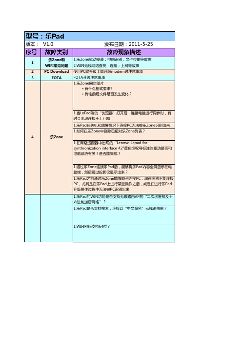
乐Pad故障判断维修参考方法20110525
19
摄像头模糊
19
摄像头模糊
1.摄像头模糊不清(目视无杂质)
1.乐Pad开机后,主界面提示“数据文件损坏,请清理后尝试
20
电子书
重新加载”,如何处理?
5
拟制 :张洪海
可能产生原因
用户使用操作环境
用户使用操作环境 用户使用操作环境 1.乐Zone需求定义问题
1.软件问题 1.用户操作问题 1.用户操作问题 1.乐Zone驱动问题
的情况,出现无声时,退出游戏做其他操作,如播放视频或音
乐,会出现其他应用也没有声音情况,如果再进入游戏汤姆
猫,操作时从无声再到有声,退出程序时其他应用也会有声
1.关机后再开机,则时间都会变成1980年,不管开关机的时间 多久
15
时钟失效
2.用户手动设置当前时间后无法保存
1.返回键不起作用,触摸失灵
16
1.系统运行时出现异常 1.SIM卡没有安装插到位 2.主板不良(SIM卡板不良) 3.SIM卡类型造成
4.3G版SIM卡不支持热拔插,若进行热 拔插则会不能识别网络(插入SIM), 必须重新开关机才能找到网络 1.电信SIM卡问题
MD系列立体声音频解码器快速安装指南-乐之邦MUSILAND
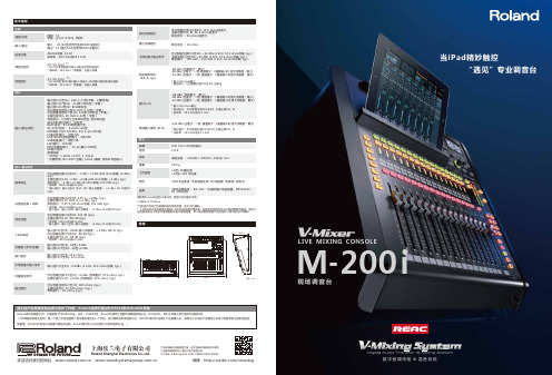
LIVE MIXING CONSOLE现场调音台数字音频传输&混音系统M -200i通道/总线通道:32总线:主L/R, 8 AUX, 4矩阵信号处理AD/DA转换: 24 bit采样率:48.0 kHz或44.1 kHz 输入/输出输入: 24 (64当使用可选的REAC设备时)输出:14 (最大54点当使用REAC设备时)调音台延时2.0 mS (typ.) *1* M-200i本地的接口输入/输出的系统总延时* 采样率:48.0 kHz * 效果器:无插入效果标量输出电平可分配输出接口(1至10): +4 dBu (负载阻抗: 10 k ohms, typ.)主输出接口(L, R): +4 dBu (负载阻抗: 10 k ohms, typ.)输出阻抗可分配输出接口(1至10): 600 ohms (typ.)主输出接口(L, R): 600 ohms (typ.)耳机接口: 49 ohms (typ.)等效输入噪声 (E.I.N.)-126 dBu (主推子:一致, 通道推子:1通道输入时,放大灵敏度:最大)* 输出接口:可分配输出接口(1至10),主输出接口(L, R)* 采样率:48.0 kHz或44.1 kHz*为改进产品对产品规格和或外观的变更,恕不另行通知。
* 1:当在REAC信号链路中使用S-4000D或交换机等设备,网络延迟将因为信号分配和复制而增加。
实际产生的延迟取决于信号分配或复制设备本身的规格。
单一信号复制设备产生的延时一般不超过200微秒。
残余噪声电平 (IHF-A, typ.)-88 dBu (所有推子:最小)-80 dBu (主推子:一致, 通道推子:1通道输入时, 放大灵敏度:最小)-61 dBu (主推子:一致, 通道推子:1通道输入时放大灵敏度:最大)* 输入150 ohms截止* 输出接口:可分配输出接口(1至10), 主输出建议负载阻抗可分配输出接口(1至10): 10 k ohms或更大主输出接口(L, R): 10 k ohms或更大耳机接口: 40 ohms或更大不饱和最大输出电平可分配输出接口(1至10): +22 dBu (1 kHz, 10 k ohms负载, typ.)主输出接口(1至10): +22 dBu (1 kHz, 10 k ohms负载, typ.)耳机接口: 150 mW + 150 mW (1 kHz, 40 ohms负载, typ.)输入/输出/其它输入接口(1至16) : XLR-3-31型(平衡,幻象供电)输入接口(17至22) : 1/4英寸耳机型(平衡)输入接口(23至24): RCA耳机型可分配输出接口(1至6): XLR-3-32型(平衡)可分配输出接口(7至10): 1/4英寸耳机型(平衡)主输出接口(L, R): XLR-3-32型(平衡)耳机接口:1/4英寸立体声耳机型, 迷你耳机型AES/EBU输出接口:光纤型REAC接口:RJ-45网络接口型RS-232C接口: 9-pinD-sub型MIDI接口 (OUT/THRU, IN): 5-pin DIN型USB闪存接口: A型USBUSB WLAN适配器接口: A型USB USB电脑接口: B型USB LAN接口: RJ45型DOC连接线接口: 10-pin最小i DIN型DC输入接口接地线端* XLR型:1 GND, 2 HOT, 3: COLD* 幻象供电: DC+48V (空载), 14mA (满载, 所有XLR型输入)频率响应可分配输出接口(1至10) : -2 dB / +0 dB (20k ohms负载,+4 dBu, typ.)主输出接口(L, R): -2 dB / +0 dB (20k ohms负载, +4 dBu, typ.)耳机接口: -3 dB / +0 dB (40 ohms负载, 150 mW, typ.)* 采样率:48.0 kHz或44.1 kHz* 输入接口:输入1至24 (Pad: ON, 输入灵敏度: +4 dBu, 20 Hz至20 kHz)动态范围可分配输出接口(1至10): 102 dB (typ.)主输出接口(L, R): 102 dB (typ.)* 采样率:48.0 kHz或44.1 kHz* 输入接口:输入1至24 (输入灵敏度: +4 dBu, 20 Hz至20 kHz)标量输入电平(变量)输入接口(1至16): -65至+4 dBu 输入接口(17至24): -28至+4 dBu 输入阻抗输入接口(1至16): 14 k ohms 输入接口(17至24): 10 k ohms总谐波失真 + 噪声可分配输出接口(1至10): 0.05 % (+4 dBu, typ.)主输出接口(L, R): 0.05 % (+4 dBu, typ.)耳机接口: 0.05 % (40 ohms负载, 150 mW, typ.)* 采样率:48.0 kHz或44.1 kHz* 输入接口:输入1至24 (输入灵敏度: +4 dBu, 20 Hz至20 kHz)1 kHz串扰输入接口(1至24): -80dB (输入灵敏度: +4 dBu, IHF-A, typ.)可分配输出接口(1至10): -88 dB (typ.)主输出接口(L, R): -88 dB (typ.)* 采样率:48.0 kHz或44.1 kHz单位 : mm不饱和最大输入电平输入接口(1至24): +22dBu (1 kHz, 20 k ohms负载, typ.)接口(L, R)-88 dBu (所有推子:最小)-80 dBu (主推子:一致, 通道推子:1通道输入时放大灵敏度:最小)-61 dBu (主推子:一致, 通道推子:1通道输入时 放大灵敏度:最大)* 输入150 ohms截止* 输出接口:可分配输出接口(1至10), 主输出接口(L, R)* 采样率:48.0 kHz或44.1 kHz屏幕LCD 132 x 64点阵背光电流 3.6 A体积桌面安装:: 491(W) x 490(D) x 198(H) mm 工作温度+5至+40摄氏度+41至+104 华氏度附件.DOCK连接线 .平板电脑支架 .AC适配器 .电源线 .说明书选购.机架安装组件: RA-10U .无线网络USB适配器:WNA1100-RL .USB闪存重量9.8 kg最小负载阻抗耳机接口: 16 ohms网络延时2.5 mS (typ.) *1* M-200i的 REAC接口输入/输出S-1608接口箱的系统总延时* 采样率:48.0 kHz * 效果器:无插入效果请使用Roland出品的USB闪存。
Microsoft Azure StorSimple 8600 硬件安装指南说明书
ContentsUnpack your device (3)Prerequisites (3)Unpacking your device (3)Rack-mount your device (4)Site preparation (4)Prerequisites (5)Rack-mounting rail kit (5)Install the EBOD enclosure on the rails (5)Mounting the EBOD enclosure in the rack (7)Mounting the primary enclosure in the rack (8)Cable your device (9)Prerequisites (9)SAS cabling (9)Power cabling (11)Network cabling (13)Serial port cabling (15)A C C ELabel Description1Packing box2SAS Cables (in accessories and cables tray)3Bottom foam4Device5Top foam6Accessory box3. After unpacking the two boxes, ensure you have:a. 1 primary enclosure (the primary enclosure and EBOD enclosure are in two separate boxes).b. 1 EBOD enclosure.c. 4 power cords, 2 in each box.d. 2 SAS cables (to connect the primary enclosure to EBOD enclosure).e. 1 crossover Ethernet cable.f. 2 serial console cables.g. 1 serial-USB converter for serial access.h. 2 single QSFP-to-SFP adapters.i. 2 rack mount kits (4 side rails with mounting hardware, 2 each for the primary enclosureand EBOD enclosure), 1 in each box.j. 1 tamper-proof T10 screw driverk. Getting started documentation.If you did not receive any of the items listed above, contact technical support. The next step is to rack-mount your device. See the Rack-mount your device for details.Rack-mount your deviceThis section includes the steps required to install your Microsoft Azure StorSimple 8600 storage device in a standard 19-inch rack with front and rear posts. This device comes with two enclosures:a primary enclosure and an EBOD enclosure. Both of these need to be rack mounted.The installation consists of multiple steps each of which is discussed in the following procedures. Site preparationThe enclosures must be installed in a standard 19-inch rack that has both front and rear posts. To prepare for rack installation, ensure that:• The primary and EBOD enclosures are resting safely on a flat, stable, and level work surface (or similar).• The site where you intend to set up has standard AC power from an independent source or a rack Power Distribution Unit (PDU) with an uninterruptible power supply (UPS).• One 4U (2 X 2U) slot is available in the rack where you intend to mount the enclosures.4WARNING!Ensure you have two people available to handle the weight in case you are handling it manually.A fully configured enclosure can weigh up to 32 kg.PrerequisitesThe enclosures are designed for installation into a standard 19-inch rack cabinet with:• Minimum depth of 27.84 inches from rack post to post.• Maximum weight of 32 kg for the device.• Maximum back pressure of 5 Pascal (0.5 mm water gauge).Rack-mounting rail kitA set of mounting rails will be provided to use with the 19-inch rack cabinet. The rails have been testedto handle the maximum enclosure weight. These rails will also allow installation of multiple enclosures without loss of space within the rack. Start with the installation of the EBOD enclosure first.Install the EBOD enclosure on the railsFollow these steps to safely install the EBOD enclosure on the rails.1. With the enclosure on the work surface, remove the left and right front flange caps by pullingthe caps free. The flange caps simply snap onto the flanges.2. These rails are installed at the factory. If these are not, then install the left-rail and right-railslides to the sides of the enclosure chassis. They attach using six metric screws on each side. To help with orientation, the rail slides are marked “LH - Front” and “RH – Front,” and the end that is affixed towards the rear of the enclosure has a tapered end.12Figure 2 Attaching rail slides to the sides of the enclosure5Mounting the EBOD enclosure in the rackPerform the following steps to mount the EBOD enclosure in the rack using the rack rails that were just installed.1. Using an assistant, lift the enclosure and align it with the rack rails.2. Carefully insert the enclosure into the rails and push it completely into the rack cabinet.Figure 4 Mounting the enclosure in the rack3. Secure the enclosure into the rack by installing one provided Phillips-head screw through eachflange, left and right.4. Install the flange caps by pressing them into position and snapping them into place.79Cable your deviceThis section includes instructions to cable your device for power, network, and serial connection. PrerequisitesBefore you begin the cabling of your device, you will need:• Your primary enclosure and the EBOD enclosure, completely unpacked.• 4 power cables (2 each for the primary and the EBOD enclosure) that came with your device. • 2 SAS cables supplied with the device to connect the EBOD enclosure to the primary enclosure. • Access to 2 Power Distribution Units (PDUs) (recommended).• Network cables.• Provided serial cables.• Serial-USB converter with the appropriate driver installed on your PC (if needed).• Provided single QSFP-to-SFP adapters.• SFP cables.SAS cablingYour device has a primary and an EBOD enclosure. These enclosures need to be connected together using the SAS cables.Perform the following steps to connect the primary enclosure to the EBOD enclosure.1. Identify the primary and the EBOD enclosure. The two enclosures can be identified by looking at the respective back planes. See the following figure for guidance.I II 4321Host FabricIDII I 4321Ho s t F a b r i c D AC B 123412344321A C B 12341234432112Figure 6 Back plane view of the primary and EBOD enclosures Label Description1Primary enclosure2EBOD enclosure2. Locate the serial numbers on both the primary and the EBOD enclosure. The serial numbersticker is affixed on the back ear of each enclosure. The serial numbers must be identical on both enclosures. Contact technical support immediately if the serial numbers do not match.See the following figure to help you locate the serial numbers.1H oF a bcIIH o F a bicIDFigure 7 Rear view of the enclosure showing the location of the serial number stickerLabel Description1Ear of the enclosure3. The EBOD enclosure now needs to be connected to the primary enclosure using the providedSAS cables. Perform the following steps.a. Identify the four Serial Attached SCSI (SAS) ports on primary enclosure and EBODenclosure. The SAS ports are labeled as EBOD on primary enclosure and CTRL on theEBOD enclosure as shown in Figure 8.b. Use provided SAS cables to connect EBOD ports to CTRL ports.c. The EBOD port on Controller 0 should be connected to the CTRL port on EBOD controller0. The EBOD port on Controller 1 should be connected to the CTRL port on EBODcontroller 1. See Figure 8 for guidance.1011I II 43Host FabricIDII I 4321Ho s t F a b r i c D E B O D C B 12341234C B 12341234321CTRL 214321EBODEBOD 15A B 2346A432148A 4321CTRLA CTRL7Figure 8 SAS cabling for your deviceLabel DescriptionA Primary enclosureB EBOD enclosure1Controller 02Controller 13EBOD Controller 04EBOD Controller 15, 6SAS ports on primary enclosure (labeled EBOD)7, 8SAS ports on EBOD enclosure (labeled CTRL)Power cablingYour device has a primary enclosure and an EBOD enclosure. Both enclosures include redundant Power and Cooling Modules (PCMs). In each enclosure, each PCM must be installed and connected to different power sources to ensure high availability.Perform the following steps to cable your device for power.1. Ensure that the power switches on all the PCMs are in the OFF position.2. For the primary enclosure, connect the power cords to both PCMs. The power cords areidentified in red in the following diagram.3. Ensure that the two PCMs of the primary enclosure use separate power sources.4. Attach the power cords to the rack power distribution units as shown in the following figure.5. Repeat steps 2-4 for the EBOD enclosure.6. Turn on the EBOD enclosure by flipping each PCM’s power switch to the ON position.7. Verify that the EBOD enclosure is turned on by checking that the EBOD controller LEDs (greenLEDs on the back of the chassis) have turned ON.8. Now, turn on the primary enclosure by flipping each PCM switch to the ON position.9. Verify that the system is up by ensuring the device controller LEDs have turned ON.10. Verify that the connection between EBOD controller and device controller is active by ensuringthe SAS LEDs (4 LEDs next to the SAS port) on the EBOD controller are green.NOTICETo ensure high availability of your system, you are advised to strictly adhere to the powercabling scheme shown in the following diagram.Figure 9 Power cabling for your device12Label Description1Primary enclosure2PCM 03PCM 14Controller 05Controller 16EBOD controller 07EBOD controller 18EBOD enclosure9PDUsNetwork cablingYour device is in an active-standby confi guration: at any given time, one controller module isactive and processing all disk and network operations while the other controller module is standby.In the event of a controller failure, the standby controller immediately activates and continues allthe disk and networking operations.To support this redundant controller failover, you need to cable your device network as shown inthe following steps.1. Your device has six network interfaces on each controller, four 1 Gbps and two 10 Gbps Ethernetports. Identify the various data ports in the backplane of your device.Figure 10 Back plane of your device showing the data portsLabel Description0, 1, 4, 5 1 Gbps network interfaces2, 310 Gbps network interfaces6Serial ports13Label DescriptionA LAN with Internet accessB Controller 0C PCM 0D Controller 1E PCM 1F EBOD controller 0G EBOD controller 1H, I Hosts (for example, file servers)0-5Network interfaces6Primary enclosure7EBOD enclosureSerial port cablingPerform the following steps to cable your serial port.1. Your device has a serial port on each controller identified by a wrench icon. Locate the serialports in the backplane of your device using Figure 10.2. Identify the active controller in your device back plane. A blinking blue LED indicates thecontroller is active.3. Use the provided serial cable (if needed, the USB-serial converter for your laptop), and connectyour console or computer (with terminal emulation to the device) to the serial port of theactive controller.4. Install the serial-USB drivers shipped with this device on your computer.5. Set up the serial connection as follows: 115,200 baud, 8 data bits, 1 stop bit, no parity, flowcontrol set to None.6. Verify the connection is working by pressing Enter in the console. A serial console menushould be presented.NOTICELights-Out Management: When the device is installed in a remote data center or in acomputer room with limited access, ensure that the serial connections to both controllers are always connected to a serial console switch or similar equipment. This allows out-of-bandremote control and support operations in case of network disruption or unexpected failures.You have completed cabling your device for power, network access, and serial connection.15© 2014 Microsoft Corporation. • X19-32483-02。
手机管理软件乐助手使用手册

用手机管理软件(乐助手)怎么在电脑上直接播放手机中的视频和音乐,怎么办?手机管理软件乐助手(原联想手机管家)支持直接在电脑上播放手机中的视频和音乐进入视频菜单栏,直接点解视频缩略图中间的播放图标,软件将调用windows media player播放视频。
第一次使用的时候,需要选择windows media player 的播放设置进入音乐菜单栏,打开音乐列表,将鼠标移至想要播放的音乐文件一栏,在名称后方即附件“播放”的功能按钮,点击播放即可我想直接在手机管理软件乐助手(原联想手机管家)设置手机桌面、手机铃声,怎么办?手机管理软件您可以通过如下方法,设置手机壁纸:进入图片菜单栏,打开手机上图片的缩略图,点击缩略图或者勾选缩略图再点击上方“幻灯片播放”按钮,即可弹出大图浏览图片窗口。
选定自己想要设置为手机桌面的图片,点击在其浏览窗口右下方第二个功能图标,即可把该图片设置为手机桌面手机管理软件设置手机铃声就更简单了。
进入音乐菜单栏,打开音乐列表,将鼠标移至想要设置为铃声的音乐文件一栏,在名称后面即浮现“设为铃声”的功能按钮,点击即可完成设置。
手机管理软件联想手机管家提供USB连接方式步骤一:打开手机的USB调试模式;步骤二:打开PC端联想手机管家,并使用USB数据线,连接手机和PC;步骤三:联想手机管家将自动识别手机,(如果是首次连接,将安装手机驱动)启动联想手机管家手机端,显示连接成功,您就可以使用联想手机管家管理您的手机了。
手机管理软件手机与电脑成功连接后,又突然断开了当您遇到此类问题,请确认您使用的USB连接线是否接触不良,如没有,可能是手机中的联想手机管家软件运行被拦截,可以尝试以下解决方案:可以查看手机中是否启动了:安全管家、省电助手之类的软件,并关闭其对手机管理软件乐助手的限制,再重新连接手机与PC。
手机管理软件乐助手如何确认我已经真正打开「USB 调试」开关?有时候,在手机上“USB调试”虽然显示是勾选状态,但有可能是假象,这时候,可以先取消勾选,再进行勾选,重新激活“USB调试”开关的打开状态。
- 1、下载文档前请自行甄别文档内容的完整性,平台不提供额外的编辑、内容补充、找答案等附加服务。
- 2、"仅部分预览"的文档,不可在线预览部分如存在完整性等问题,可反馈申请退款(可完整预览的文档不适用该条件!)。
- 3、如文档侵犯您的权益,请联系客服反馈,我们会尽快为您处理(人工客服工作时间:9:00-18:30)。
详细咨询请参考:
尊敬的联想樂pad 用户:
您好,您可以在联想移动官方网站 下载樂Zone 软件(下载网址:/lepad/download.html#A1),安装到您的PC 上,就可以通过樂Zone 软件同步您PC 上的数据到您的樂Pad 上。
樂zone 目前仅支持以下操作系统:Windows XP (SP2及以上)英文版,简体中文版,繁体中文版、windows 7英文版,简体中文版,繁体中文版(不支持VISTA,和windows2000)
1、首先安装.net framework 3.5,安装完毕后重启电脑.(windows 7用户请跳过第一步):
.net framework 3.5(大小:231.5M )下载链接(复制下载链接到迅雷:新建下载任务): /download/2/0/e/20e90413-712f-438c-988e-fdaa79a8ac3d/d otnetfx35.exe
2、其次安装樂zone :安装樂zone 前请将樂pad 连接到电脑,再进行安装。
樂zone 下载链接(复制下载链接到迅雷:新建下载任务): /lepad/download/lezone.rar
3、安装樂zone 后,将樂pad 和电脑重启,重启后即可在樂zone 中识别到樂pad 。
(如果无法识别到乐pad ,请查看备注1和2)
备注1:手动更新驱动步骤(建议关闭防火墙和杀毒软件)
在PC 设备管理器中右键点击[Lenovo Lepad for synchronization interface ]更新驱动程序,
1、在硬件更新向导中选择[从列表或指定位置安装(高级)],
2、下一步选择“在搜索中包括这个位置”后,点击[浏览]将路径指向乐zone
程序安装路
径(默认路径是:C:\Program Files\Lenovo\Lezone\hybrid\drivers),(如下图)
5、找到[LepadSyncInterface.inf]驱动文件,打开下一步会出现"更新驱动程序警告"不要理会该提示,继续安装。
备注2:手动更新ADB驱动步骤(建议关闭防火墙和杀毒软件)
1. 在PC设备管理器中右键点击[Lenovo ADB Interface]更新驱动程序,
2、在硬件更新向导中选择[从列表或指定位置安装(高级)],
3、下一步选择[从磁盘安装]后,点击[浏览]将路径指向乐zone程序安装路径(默认路径是:C:\Program Files\Lenovo\Lezone\hybrid\drivers\adb_usb_driver),
4、找到[Lepad_Adb.inf]驱动文件,打开下一步会出现"更新驱动程序警告"不要理会该提示,继续安装。
详细咨询请参考:。
