XAPro-2011-cn
先锋2011年11月1日
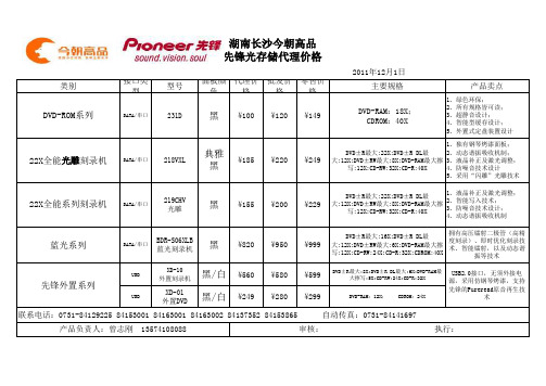
类别接口类型型号面板颜色代理价格批发价格零售价格主要规格产品卖点USB XD-10外置刻录机黑/白¥560¥580¥599DVD±R最大:8X;DVD±R DL最大:6X;DVD-RAM最大擦写:5X;CD-RW:24X;CD-R:32X USB XD-01外置DVD 黑/白¥249¥280¥299DVD-RAM:12X; CDROM:24X2011年12月1日联系电话:0731-******** 84153001 84163001 84163002 84137352 84153865 自动传真:0731-********产品负责人:曾志刚 135********审核: 执行:231D 218VXL 219CHV 光雕BDR-S06XLB 蓝光刻录机黑典雅黑DVD-ROM系列22X全能光雕刻录机22X全能系列刻录机蓝光系列先锋外置系列SATA/串口SATA/串口SATA/串口SATA/串口黑黑¥100¥185¥155¥820¥149¥249¥229¥999¥120¥220¥200¥950USB2.0接口,无须外接电源,采用仿钢琴烤漆,支持先锋的Pureread原音再生技术湖南长沙今朝高品先锋光存储代理价格1、绿色环保;2、所有规格皆可读;3、超静音设计;4、智能型缓存设计;5、外置式定盘装置设计1、独有钢琴烤漆面板;2、动态谐振吸收机制;3、液晶补正及激光调整;4、防噪音技术设计5、采用“闪雕”光雕技术1、液晶补正及激光调整;2、智能写入技术;3、防噪音技术设计;4、动态谐振吸收机制拥有高压镭射二极管(高精度刻录)、即时优化刻录技术、智能镭射,以及动态谐振等技术DVD-RAM:18X;CDROM:40X DVD±R最大:22X;DVD±R DL最大:12X;DVD±RW最大:8X;DVD-RAM最大擦写:12X;CD-RW:32X;CD-R:40X DVD±R最大:22X;DVD±R DL最大:12X;DVD±RW最大:8X;DVD-RAM最大擦写:12X;CD-RW:32X;CD-R:40X DVD±R最大:16X;DVD±R DL最大:12X;DVD±RW最大:6X;DVD-RAM最大擦写:12X;CD-RW:24X;CD-R:32X;CDROM:40X。
AUTODESK 2011全系列产品密钥

AUTODESK 2011全系列产品密钥001C1 AutoCAD 2011057C1 AutoCAD LT 2011128C1 Autodesk 3ds Max 2011129C1 AutoCAD Map 3D 2011140C1 AutoCAD OEM 2011151C1 RealDWG 2011185C1 AutoCAD Architecture 2011200C1 Autodesk Design Academy 2011206C1 AutoCAD Mechanical 2011208C1 Autodesk Inventor 2011213C1 AutoCAD Utility Design 2011225C1 AutoCAD Electrical 2011235C1 AutoCAD MEP 2011237C1 AutoCAD Civil 3D 2011240C1 Autodesk Revit Architecture 2011241C1 AutoCAD Revit Architecture Suite 2011255C1 Autodesk Revit Structure 2011256C1 AutoCAD Revit Structure Suite 2011257C1 AutoCAD Revit MEP Suite 2011262C1 Autodesk Showcase 2011295C1 Autodesk Showcase Professional 2011340C1 AutoCAD Raster Design 2011424C1 Autodesk Quantity Takeoff 2011426C1 AutoCAD Plant 3D 2011448C1 AutoCAD P&ID 2011495C1 Autodesk 3ds Max Design 2011498C1 Autodesk Mudbox 2011506C1 Autodesk Navisworks Simulate 2011507C1 Autodesk Navisworks Manage 2011529C1 Autodesk Inventor LT 2011535C1 T1 Enterprise Multi-flex 2011545C1 AutoCAD LT Civil Suite 2011546C1 Autodesk Robot Structural Analysis 2011547C1 Autodesk Robot Structural Analysis Professional 2011548C1 Autodesk Entertainment Creation Suite Ultimate - Secondary Schools 2011 549C1 Autodesk Vault Collaboration 2011555C1 Autodesk Vault Office 2011559C1 Autodesk Vault Workgroup 2011562C1 AutoCAD ecscad 2011569C1 Autodesk Vault Professional 2011570C1 Autodesk Simulation Moldflow Adviser Standard 2011571C1 Autodesk Simulation Moldflow Adviser Premium 2011572C1 Autodesk Simulation Moldflow Adviser Ultimate 2011573C1 Autodesk Simulation Moldflow Insight Standard 2011574C1 Autodesk Simulation Moldflow Insight Premium 2011575C1 Autodesk Simulation Moldflow Insight Ultimate 2011576C1 Autodesk Simulation Moldflow Design Link 2011577C1 Autodesk Simulation Moldflow CAD Doctor 2011579C1 Autodesk Simulation Moldflow Synergy 2011589C1 Autodesk Revit MEP 2011590C1 Autodesk Softimage 2011596C1 AutoCAD Inventor LT Suite 2011636C1 Autodesk Inventor Engineer-to-Order Series Distribution Fee 2011 651C1 Autodesk Education Master Suite 2011654C1 Autodesk Product Design Suite for Education 2011657C1 Autodesk Maya 2011660C1 Autodesk Maya Entertainment Creation Suite Standard 2011661C1 Autodesk 3ds Max Entertainment Creation Suite Standard 2011 662C1 Autodesk Softimage Entertainment Creation Suite 2011666C1 Autodesk Inventor Publisher 2011667C1 Autodesk Simulation Multiphysics 2011669C1 Autodesk Simulation Mechanical 2011675C1 Autodesk Opticore Studio Professional 2011692C1 Autodesk Real-Time Ray Tracing Cluster 2011710C1 Autodesk Alias Automotive 2011712C1 Autodesk Alias Design 2011718C1 mental ray Standalone 2011727C1 Autodesk MotionBuilder 2011736C1 Autodesk Alias Surface 2011741C1 Autodesk SketchBook Designer 2011752C1 Autodesk Inventor Engineer-to-Order Server 2011757C1 Autodesk Factory Design Suite Premium 2011760C1 Autodesk Factory Design Suite Ultimate 2011763C1 Autodesk Plant Design Suite Premium 2011764C1 Autodesk Plant Design Suite Ultimate 2011765C1 Autodesk Building Design Suite Premium 2011766C1 Autodesk Building Design Suite Ultimate 2011767C1 AutoCAD Design Suite Standard 2011768C1 AutoCAD Design Suite Premium 2011769C1 AutoCAD Design Suite Ultimate 2011770C1 Autodesk Alias TC Integrator for GM771C1 GM CAD Convertors 2011774C1 Autodesk 3ds Max Entertainment Creation Suite Premium 2011 775C1 Autodesk Maya Entertainment Creation Suite Premium 2011 777C1 AutoCAD for Mac 2011781C1 Autodesk Product Design Suite Ultimate 2011782C1 Autodesk Product Design Suite Premium 2011783C1 Autodesk Product Design Suite Standard 2011784C1 Autodesk Building Design Suite Standard 2011785C1 Autodesk Infrastructure Design Suite Ultimate 2011786C1 Autodesk Infrastructure Design Suite Premium 2011787C1 Autodesk Infrastructure Design Suite Standard 2011788C1 Autodesk Plant Design Suite Standard 2011789C1 Autodesk Factory Design Suite Standard 2011793C1 Autodesk Entertainment Creation Suite Ultimate 2011796C1 Autodesk Infrastructure Map Server 2011797C1 Autodesk Inventor Professional 2011798C1 Autodesk Inventor OEM 2011801C1 Autodesk Vault Collaboration AEC 2011805C1 Autodesk Inventor Engineer-to-Order Series 2011808C1 Autodesk Infrastructure Modeler 2011809C1 Autodesk Simulation CFD 2011810C1 Autodesk Simulation CFD Advanced 2011811C1 Autodesk Simulation CFD Motion 2011812C1 Autodesk Simulation CFD Design Study Environment 2011 815C1 Autodesk Simulation CFD Connection for NX 2011819C1 Autodesk Simulation CFD Connection for ACIS 2011822C1 Autodesk Simulation CFD Connection for Pro/ENGINEER 2011 824C1 Autodesk Simulation CFD Connection for Parasolid 2011827C1 AutoCAD LT for Mac 2011828C1 Autodesk Revit LT 2011829C1 Autodesk Revit 2011835C1 Autodesk PLM 360 2011837C1 Autodesk Simulation DFM 2011839C1 Autodesk Fabrication CADmep 2011840C1 Autodesk Fabrication FABmep 2011841C1 Autodesk Fabrication ESTmep 2011842C1 Autodesk Fabrication CAMduct 2011843C1 Autodesk Fabrication Tracker 2011844C1 Autodesk Fabrication CAMduct Components 2011 845C1 Autodesk Fabrication RemoteEntry 2011848C1 Autodesk Simulation 360 2011854C1 Autodesk BIM 360 2011857C1 Autodesk Simulation 360 Ultimate 2011A46C1 Autodesk T-Splines Plug-in for Rhino 2011A47C1 Instructables Direct 2011A48C1 Instructables Membership 2011A49C1 Instructables Other 2011A50C1 Autodesk tsElements Plug-in 2011。
NETGEAR A8000 无线AXE3000 WiFi 6 6E USB 3.0适配器用户手册

RechtsvorschriftenMärz 2023LieferumfangSupport und CommunityUnter netgear.de/support finden Sie Antworten auf Ihre Fragen und die neuesten Downloads.Hilfreiche Tipps finden Sie auch in unserer NETGEAR Community unter /de.Informationen zur Einhaltung der rechtlichen Vorschriften, einschließlich der EU-Konformitätserklärung, finden Sie unter: https:///de/about/regulatory/.Lesen Sie das Dokument zur Einhaltung rechtlicherVorschriften, bevor Sie das Gerät an die Stromversorgung anschließen.Gilt nur für 6-GHz-Geräte: Verwenden Sie das Gerät nur in Innenräumen. Der Betrieb von 6-GHz-Geräten auf Ölplattformen sowie in Autos, Zügen, Booten und Flugzeugen ist verboten. Davon ausgenommen ist der Betrieb dieses Geräts in großen Flugzeugen mit einer Flughöhe von über 3.000 Metern. Es ist nicht gestattet,Sender im Frequenzbereich 5,925–7,125 GHz zur Steuerung oder Kommunikation mit unbemannten Flugzeugsystemen zu verwenden.© NETGEAR, Inc., NETGEAR und das NETGEAR Logo sind Marken von NETGEAR, Inc. Jegliche nicht zu NETGEAR gehörende Marken werden nur zu Referenzzwecken verwendet.NETGEAR, Inc.350 East Plumeria Drive San Jose, CA 95134, USANETGEAR INTERNATIONAL LTD Floor 6, Penrose Two, Penrose Dock, Cork, T23 YY09, Irland4. Befolgen Sie die Schritte, die auf demBildschirm angezeigt werden, um die Installation abzuschließen.HINWEIS: Das Installationsprogramm bietet Ihnen die Möglichkeit, andere WLAN-Adapter zu deaktivieren. Für eine optimale Leistung empfehlen wir Ihnen, die anderen Adapter zu deaktivieren.5. Klicken Sie auf Finish (Fertigstellen), um denInstallationsassistenten zu beenden.Schritt 5: Verbindung mit einem WLAN-Netzwerk herstellen1. Öffnen Sie die WLAN-Netzwerkeinstellungenauf Ihrem Computer, indem Sie mit der rechten Maustaste auf das WLAN-Symbol () oder aufdas Symbol …Kein Internetzugriff“ () in der unteren rechten Ecke des Bildschirms klicken.Schritt 1: Datei des A8000-Installationsprogrammskopieren oder herunterladenSchließen Sie den mitgelieferten USB-Speicherstick an Ihren Computer an und kopieren Sie die A8000-Installationsdatei (A8000 Windows Installation Program V1.x.x.xxx_x.x.xx.zip ) auf IhrenComputer. Entfernen Sie den USB-Stick, nachdem Sie die Datei des Installationsprogramms auf Ihren Computer kopiert haben.Anstatt den USB-Speicherstick zu verwenden, können Sie auch /A8000-downloadbesuchen und das A8000-Installationsprogramm dort herunterladen.Schritt 2: Auf aktuellste Windows-Version prüfenVergewissern Sie sich, dass auf Ihrem Computer eine aktuelle Version von Windows 10 oder Windows 11 ausgeführt wird.Weitere Informationen zum Aktualisieren von Windows finden Sie im Microsoft Support-Artikel …Windows aktualisieren “.HINWEIS: Für die Verbindung mit dem 6-GHz-Frequenzband (WiFi 6E) ist Microsoft Windows 11 erforderlich. Windows 10 unterstützt nur die 2,4-GHz- und 5-GHz-Bänder.Schritt 3: Anschließen des AdaptersWählen Sie die Verbindung, die am besten für Sie geeignet ist.Schritt 4: A8000-Installationsprogramm ausführen1. Klicken Sie mit der rechten Maustaste aufdie Datei des A8000-Installationsprogramms (A8000 Windows Installation ProgramV1.x.x.xxx_x.x.xx.zip ), die Sie zuvor auf Ihren Computer kopiert haben, und wählen Sie Extract All (Alle extrahieren) aus.2. Klicken Sie auf Extract (Extrahieren).3. Doppelklicken Sie auf A8000 WindowsInstallation Program V1.x.x.xxx_x.x.xx.exe , um das Installationsprogramm zu starten.HINWEIS: Wenn das FensterBenutzerkontensteuerung angezeigt wird, in dem Sie gefragt werden, ob Sie der App erlauben möchten, Änderungen an Ihrem Gerät vorzunehmen, wählen Sie Yes (Ja).2. (Nur Windows 11) Klicken Sie auf Manage Wi-Ficonnections (WLAN-Verbindungen verwalten) (>) neben dem WLAN-Symbol.3. Wählen Sie den Namen Ihres Netzwerks aus.4. Klicken Sie auf Connect (Verbinden).5. Geben Sie den Sicherheitsschlüssel (WLAN-Passwort) für das Netzwerk ein.6. Klicken Sie auf Next (Weiter).Wenn die Meldung …Connected, secured“ (Verbunden, gesichert) angezeigt wird, ist die Einrichtung abgeschlossen.7. Drücken Sie die ESC -Taste oder klickenSie auf den Desktop, um die WLAN-Netzwerkeinstellungen zu verlassen.Schritt 6: Registrieren Ihres A8000Scannen Sie den QR-Code oder besuchen Siehttps:///register, um Ihren A8000 zu registrieren und die neuesten Treiber-Updates und andere Informationen zu erhalten.。
AXIS T61 Audio and I O Interface Series 用户手册说明书

AXIS T61Audio and I/O Interface Series AXIS T6101Audio and I/O InterfaceAXIS T6112Audio and I/O Interface 用户手册目录关于本手册 (3)产品概述 (4)解决方案概述 (5)其他设置 (6)关于产品 (6)关于摄像机的内置帮助 (6)音频 (6)事件 (7)故障排查 (9)技术问题、线索和解决方案 (9)规格 (10)LED指示灯 (10)连接器 (10)关于本手册关于本手册本用户手册描述了几种产品。
这意味着您可能会找到不适用于您产品的说明。
产品概述产品概述AXIS T6101和AXIS T61121LED指示灯2I/O连接器3音频输出4音频输入5网络连接器(PoE输入)6网络连接器(PoE输出)7PoE交换机(2类和3类)AXIS T61121麦克风2外壳3侧盖4安装支架其他设置其他设置关于产品当您将产品连接到具有更新固件版本的支持Axis网络摄像机时,摄像机网页中将显示音频和I/O的设置。
您可通过摄像机网页进行本手册中描述的设置。
关于摄像机的内置帮助您可通过摄像机网页访问内置帮助。
该帮助提供了产品的功能及其设置的更详细信息。
音频向录像添加音频打开音频:1.转到设置>音频,然后打开允许音频。
2.转到输入>类型,然后选择您的音频源。
编辑用于录制的流配置文件:3.转到设置>流,然后单击流配置文件。
4.选择流配置文件,然后单击音频。
5.选中此复选框,然后选择包含。
6.单击保存。
7.单击关闭。
允许双向音频通信注当您在摄像机的用户界面中设置了双向音频通信后,请使用视频管理系统来利用该功能。
该示例解释如何通过产品进行音频通信。
将麦克风和扬声器连接到产品:1.将麦克风连接至音频输入接头。
2.将扬声器连接至音频输出接头。
其他设置允许在摄像机网页中使用双向音频:1.转到设置>流,并包含音频。
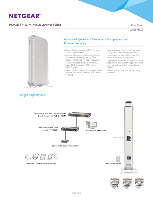
ProSAFE 无线N网络接入点WNAP210v2说明书
Network Management
• Remote configuration and management through Web browser, SNMP or telnet with command line interface (CLI)
• SNMP management supports SNMP MIB I, MIB II, 802.11 MIB a nd proprietary configuration MIB
Yes 5.8 Watts
ProSAFE Dual Band Wireless-N Access Point (WNDAP350)
2.4GHz and 5.0GHz
600Mbps
Yes
10.75 Watts
ProSAFE Dual Band Wireless-N Access Point (WNDAP360)
Block SSID Broadcast Secure SSH Telnet Secure Socket Layer (SSL) Remote management login Peer-to-peer blocking so users may not access another user’s PC MBSSID/VLAN Support WPA Support (WPA2 – Enterprise, 802.11i) User Interface Browser-based Interface Accepts accessory antennas Easy ceiling mounting/wall mounting Controller management
Connects to desktop PC
Tombstones

&ffiw&ffi s I **ssffi ffi$s I **ffi &ffi
REY: $E?1'EX'lBER
*-
*-?,41-{}*&am#39;i
?'*sxafuskrlm*s
Capital inarkets offer corporations varied ways to raise funds. This Note presents summary irrformation lor a selection of corporate securities issued cluring 2009-2010 foli.ot'ving the filrancial crisis of 2008-2009. They include three issues of senior unsecured r'rotes, one floating rate note, ofle commotl stock offering, and o:re convertible note. The issuers are Microsoft, Coca-Cola Enierprises, Norfolk Southern, IBM, Ford N,Iotor, and Cephalon. Seiected supplementary data on the issuers are summarized in HNhibit 1. A short glossary of tetms appears at the end af the Note.
7685,
?011, 2012
I\esiclert anri Felotvs of Hrrrartl Coliege.
真实世界接受IGU治疗的RA患者的人群特征、疗效及影响因素

患者的临床特征及 治 疗 前 后 各 项 临 床 指 标 和 免 疫 学
获西安交通大学第一附属医院伦理委员会批准(
2018
]
,
伦审医字第[
号)
所有患者均签署知情同意书。
067
1.
2 纳入和排除标准
1.
2.
1 纳 入 标 准 ① 所 有 患 者 均 符 合 2010 年 由
nhu
a,LÜ X
i
a
ohong,ZHU L
i,ZHANG Wa
nq
i,HELan
(
Depa
r
tmen
to
fRheuma
t
o
l
ogyandImmuno
l
ogy,TheF
i
r
s
tAf
f
i
l
i
a
t
ed Ho
sp
i
t
a
lo
f
Xi’
anJ
i
ao
t
ong Un
i
ve
r
s
i
t
an710061,Ch
i
na)
y,Xi’
RF)、抗 环 瓜 氨 酸 肽(
ACPA)、免 疫 球 蛋 白 (
I
I
gG、
gA 和
I
ACPA 阳 性 率 明 显 低 于 IGU 联 合 甲 氨
gM)、淋巴细胞 亚 群,同 时 观 察 记 录 不 良 反 应。 结 果 IGU 组 RA 患 者 病 程、
蝶 呤(me
t
ho
t
r
Xantrex技术有限公司新世代自由SW系列电源充电器说明说明书

Over-temperature shutdown
541 Roske Drive, Suite A
Automatic overload protection
Elkhart, Indiana
Short-circuit protection USA 46516
Integrated, resettable AC breakers
2000
Watts
3000
Watts
Certified to CSA Standard C22.2 No. 107.1 UL 458 with marine supplement FCC Class B
Parallel and Series Stacking - NEW FEATURE Parallel stacking enables the Freedom SW inverter/chargers to double the AC output in inverter mode Series stacking enables the Freedom SW inverter/chargers to generate 120/240 V split phase output²
Regulatory & Environmental Compliance
Flooded / gel / AGM 1 leg of 30 A < 20 ms - 4°F to 140°F (- 20°C to 60°C) - 40°F to 185°F (- 40°C to 85°C) 7.75 x 13.5 x 15.25” (19.7 x 34.3 x 38.7 cm) 27.5 kg (60.5 lbs) 2 years 1 11.8 x 17.1 x 20.5” (30 x 43.5 x 52.2 cm) 30 kg (66 lbs) 815-2012
NPort Express DE-211硬件安装指南(第八版)说明书

NPort Express DE-211 Hardware Installation GuideFor DE-211Eighth Edition, May 2011/product© 2011 Moxa Inc. All rights reserved.NPort Express DE-211Hardware Installation Guide The software described in this manual is furnished under a license agreement and may be used only in accordance with the terms of thatagreement.Copyright Notice© 2011 Moxa Inc. All rights reserved.TrademarksThe MOXA logo is a registered trademark of Moxa Inc.All other trademarks or registered marks in this manual belong to theirrespective manufacturers.DisclaimerInformation in this document is subject to change without notice and does not represent a commitment on the part of Moxa.Moxa provides this document as is, without warranty of any kind, either expressed or implied, including, but not limited to, its particular purpose. Moxa reserves the right to make improvements and/or changes to this manual, or to the products and/or the programs described in this manual, at any time.Information provided in this manual is intended to be accurate and reliable. However, Moxa assumes no responsibility for its use, or for any infringements on the rights of third parties that may result from its use. This product might include unintentional technical or typographical errors. Changes are periodically made to the information herein to correct such errors, and these changes are incorporated into new editions of the publication.Technical Support Contact Information /supportMoxa AmericasToll-free: 1-888-669-2872 Tel: +1-714-528-6777 Fax: +1-714-528-6778Moxa China (Shanghai office)Toll-free: 800-820-5036 Tel: +86-21-5258-9955 Fax: +86-21-5258-5505Moxa EuropeTel: +49-89-3 70 03 99-0 Fax: +49-89-3 70 03 99-99Moxa Asia-PacificTel: +886-2-8919-1230 Fax: +886-2-8919-1231Table of Contents1.Introduction (6)Features (7)Product Specifications (8)Package Checklist (9)Front/Top/Rear/Bottom Panel Views (10)2.Overview (11)LED Indicators (12)Housing (13)DIN Rail (13)Wall Mount (14)3.Serial Installation (15)DIP Switch Settings (16)Female DB25 Connector Pinout (17)RS-232 Wiring (17)RS-422 Wiring (19)Using a DB25 Connector (19)Using the Optional Terminal Block (20)RS-485 Wiring (20)Using a DB25 Connector (20)Using the Optional Terminal Block (21)Enabling a Termination Resistor (23)Enabling the Built-In 120 Ω Terminator (23)Enabling a User-Supplied Terminator (24)4.Ethernet Installation (25)Connecting to the Ethernet Port (26)Connecting to a Hub or Switch (26)Connecting to a PC (26)5.Power Connection (27)Using the Power Adapter (28)Using Power Over Serial (28)Power Status Check (31)A.Return Procedure (32)pliance Notice (33)1Introduction Welcome to Moxa NPort Express, a compact palm-sized communications device that allows you to control RS-232/422/485 serial devices over a TCP/IP Ethernet.The following topics are covered in this chapter:❒Features❒Product Specifications❒Package Checklist❒Front/Top/Rear/Bottom Panel ViewsNPort Express DE-211 provides a data communications solution for connecting Windows and Linux hosts to asynchronous serial devices over a TCP/IP Ethernet. You may connect your Windows host to a nativeRS-232/422/485 serial port, or your PC-based Linux host to a real tty port, through a TCP/IP Ethernet. With one asynchronous serial port connection on one end, and a 10 Mbps Ethernet connection on the other, NPort Express allows virtually any serial device to attach to a network. NPort Express works like an add-on single-port serial board to your PC server, but with one major advantage—the TCP/IP network. Since the host communicates with the COM port on NPort Express over a TCP/IP network, you are able to control your asynchronous serial device from virtually any location.Although it connects through the virtual link of the Ethernet, the port on NPort Express is recognized as a real COM port by Windows or a real tty port by Linux. NPort Express provides both the basic transmit/receive data functions, as well as RTS, CTS, DTR, DSR, and DCD control signals. NPort Express can be used with your existing applications that support serial communication, and come with a utility program providing a simple step-by-step installation procedure and a maintenance wizard that gives you easy access to your asynchronous device.Features•3-in-1 RS-232/422/485 interface and 10 Mbps Ethernet •Supports 4- and 2-wire RS-485 with patented ADDC™ and built-in terminator•Supports industrial 12/24 VDC power input and optional Power over Serial•Terminal block accessory for easy RS-422/485 serial wiring •Supports MAC based IP configuration•Supports configuration store and copy for easy deployment •Supports Windows Real COM driver and Linux real TTY driver •Supports Driver Mode, TCP Server/Client, UDP Server/Client, Ethernet Modem, Pair Connection7Product SpecificationsLAN: 10BaseTSerial: RS-232/422/485 (DIP switch selectable)Number of Ports: 1Signals:RS-232: TxD, RxD, RTS, CTS,DTR, DSR, DCD, GNDRS-422: TxD+/-, RxD+/-, GNDRS-485 2-wire: Data+/-, GNDRS-485 4-wire: TxD+/-, RxD+/-, GNDSpeed: 150 bps to 230.4 KbpsParity: None, Even, Odd, Space, MarkData Bits: 5, 6, 7, 8Stop Bits: 1, 1.5, 2Real COM drivers for: Windows95/98/ME/NT/2000/XP/2003/Vista/2008/7/XP x64/2003 x64/Vista x64/2008 x64/7 x64Real TTY driver for: Linux 2.4.x, 2.6.x kernelFixed TTY drivers for: SCO Unix, SCO OpenServer 5,OpenServer 6, UnixWare 7, UnixWare 2.1, SVR4.2, QNX 4.25, QNX 6, Solaris 10, FreeBSD 5, FreeBSD 6Driver Mode, TCP Server, TCP Client, UDP Server/Client, Ethernet Modem, Pair ConnectionSerial consoleTelnet consoleNPort Configurator for Windows/LinuxReal COM Installer for WindowsMonitor Utility for WindowsFirmware upgrade function supportedPower requirements: DC 12V to 30V150 mA (max.) at 12V92 mA (max.) at 24Operating temp.: 0 – 55◦COperating humidity: 5 – 95% RHDimensions (W×D×H): 90 × 100.4 × 22 mm (with ears),867 × 100.4 × 22 mm (without ears) Surge protection: 15 KV ESD (RS-232), 12KV ESD (RS-422/485) Magnetic isolation: 1.5 KV for EthernetRegulatory approvals: EMC: CE Class B, FCC Class BSafety: UL 60950-1, EN 60950-1 Package Checklist• 1 NPort Express DE-211•Quick Installation Guide•NPort Documentation & Software CD•Product Warranty BookletOptional AccessoriesNP21101 30 cm DB25 male to DB9 female RS-232 cableNP21102 30 cm DB25 male to DB9 male RS-232 cableNP21103 DB25 terminal block kit for RS-422/485DK-35A For 35 mm DIN Rail; includes 4 screws910Front/Top/Rear/Bottom Panel Views1. Female DB25 serial port2. DIN Rail screw holes3. Wall mount screw holes4.RJ45 10BaseT Ethernet port5. Reset button—presscontinuously for a. 3 sec to erasepasswordAfter3 sec, theready LED will flash on/off every half second. Release the reset button at this time to erase password.b. 10 sec to loadfactory defaults After 10 sec, the ready LED will flash on/off every fifth of a second. Release the reset button at this time to load factory defaults.6. DIP Switches7. Power input8. Rubber base pads2OverviewThe following topics are covered in this chapter:❒LED Indicators❒HousingDIN RailWall MountLED IndicatorsNPort Express’s top panel contains five LED indicators, as described in the following table.LED Name LED Color LED FunctionPWR red Power is on.off Power is off, or power error condition exists. Link orange 10 Mbps Ethernet connection.off Ethernet cable is disconnected, or has ashort.Ready green NPort Server system is ready.blinking NPort is requesting an IP address from theDHCP or BootP server. After receiving theIP, the LED will stop blinking.Note: The LED will also blink when you pressthe reset button; see page 1-5 for details.off NPort Server has malfunctioned.Serial Tx green Serial data is being transmitted.off Serial data is not being transmitted. Serial Rx orange Serial data is being received.off Serial data is not being received.1213DIN RailFor many industrial applications, you will find it convenient to use the DIN Rail attachments, as shown below.STEP 1: Use 2 screws per ear to attach DIN Rail mounts to each of NPort Express’s two ears.⇒STEP 2: Insert the top of the DIN Rail into slot A of the DIN Rail mount.STEP 3: Push the bottom of NPortExpress so that the bottom of the DIN Rail snaps into slot B of the DIN Rail mount.NOTE The Din Rail mounting kit is an optional accessory.To remove NPort Express from the DIN Rail, simply reverse Steps 2 and 3 above by grasping the bottom of the NPort Express unit with both hands, and then using your fingers to pull down slightly on the DIN Rail mounts at slot B. This releases the bottom of the DIN Rail from the DIN Rail mount.14For many industrial applications, you will find it convenient to mount NPort Express on the wall, using two screws, as indicated below.STEP 1: Screw two screws, separated by 7.8 cm, into the wall. The heads of the screws should be no greater than 6.5 mm in diameter, and theshafts should be no greater than 3 mm in diameter. Do not screw thescrews in all the way—leave a space of about 2 mm to allow room forsliding the NPort Express unit’s ears between the wall and the screws.STEP 2: Insert the two screw heads through the large parts of the keyhole shaped apertures, and then slide NPort Express downwards, as indicated.STEP 3: For added stability, simply tighten the two screws.To remove NPort Express from the wall mount, simply reverse Steps 2 and 3.3Serial InstallationThe following topics are covered in this chapter:❒DIP Switch Settings❒Female DB25 Connector Pinout❒RS-232 Wiring❒RS-422 WiringUsing a DB25 ConnectorUsing the Optional Terminal Block❒RS-485 WiringUsing a DB25 ConnectorUsing the Optional Terminal Block❒Enabling a Termination ResistorEnabling the Built-In 120 Ω TerminatorEnabling a User-Supplied TerminatorDIP Switch SettingsThe top panel of NPort Express contains the following table, which describes how to set up the serial port using the four DIP switches located on NPortSW1 SerialConnectionSW2 SW3 SW4 Serial Interface ModeOFF OFF OFF RS-232ON RS-232ConsoleOFF ON ON RS-422ON OFF ON 4-wire RS-485 by RTSOFF Data Comm ON ON ON 4-wire RS-485 by ADDC ON OFF OFF 2-wire RS-485 by RTS ON ON OFF 2-wire RS-485 by ADDCSwitch SW1 controls the function of the serial port (ON, or up, for RS-232 Console connection, and down for Data Communication, such as when NPort Express is connected to your serial device). Note that after changing the setting of SW1, NPort Express will reboot to initialize the new setting. You must wait a few seconds for the green Ready light to blink off and then on again, indicating that the function of the serial port has been changed.Switches SW2, SW3, and SW4 control the serial port’s data communication Interface Mode. (Note that RTS stands for Ready To Send and ADDC stands for Automatic Data Direction Control.)Keep the following points in mind when setting the DIP switches.RS-232 ConsoleTo use the serial port as a console connection, such as when using MOXA PComm Terminal Emulator or HyperTerminal, set SW1 to the ON position. Telnet ConnectionSome setup procedures can be carried out through a Telnet connection, during which data is transmitted through NPort Express’s Ethernet port. However, you must set SW1 to the OFF position to establish a Telnet connection.1617Female DB25 Connector Pinout* This pin is reserved debugging. Connections this pin yourself could result in irreparable damage to your device.RS-232 Wiring* NP21101 is an optional accessory for DE-21118* NP21102 is an optional accessory for DE-211NOTE The following pinout diagram shows how to use a DB25 (M) toDB25 (F) cable19NOTE In Ethernet Modem Mode, you need a special cable—shown in the following pinout diagram—to simulate a DCD signal.RS-422 WiringUsing a DB25 Connector20Using the Optional Terminal BlockNOTE Use a flathead screwdriver to tighten the two attachment screwsthat connect the terminal block to NPort Express.RS-485 WiringUsing a DB25 Connector21Using the Optional Terminal Block4-wire RS-485 Terminal Block WiringNOTEUse a flathead screwdriver to tighten the two attachment screws that connect the terminal block to NPort Express.222-wire RS-485 Terminal Block WiringNOTE Use a flathead screwdriver to tighten the two attachment screws that connect the terminal block to NPort Express.NOTE When setting up a multidrop network, a daisy-chained network should be used. Construct your device-to-device wiring as indicated in the above figure.23For RS-422/485 serial communications, when an electrical signal travels through two different resistance junctions in a transmission line, the impedance mismatch will sometimes cause signal reflection. Signal reflection causes signal distortion, which in turn will contribute tocommunication errors. The solution to this problem is to establish the same impedance at the line ends as in the line itself, by terminating them with resistors.The impedance of the termination resistor should equal the characteristic impedance of the transmission line. The resistors should be added near the receiving side.Enabling the Built-In 120 Ω TerminatorTo enable NPort Express’s built-in 120 Ω termination resistor, you mus t short the bottom two pins of jumper 6 (JP6), on DE-211’s circuit board. To do this:1. Use a screwdriver to remove DE-211’s outer protective case, andthen locate JP6, as shown in the figures below.2. By default, the top two pins of JP6 are shorted, which means that thebuilt-in 120 Ω termination resistor is disabled (completely removing the jumper from the pins also disables the resistor).3. Use the jumper to short the bottom two pins of JP6 to enable thebuilt-in 120 Ω termination resistor.When using the terminal block, you may install your own external terminator resistor by connecting the ends of the resistor directly to inputs 2 and 3, or by connecting the two ends of the resistor to the wires that emanate from inputs 2 and 3, as shown in the following diagrams. Enabling a user-supplied Terminator on-the-wireEnabling a user-supplied Terminator on-the-block244Ethernet InstallationThe following topics are covered in this chapter:❒Connecting to the Ethernet PortConnecting to a Hub or SwitchConnecting to a PCNPort Express DE-211 Ethernet Installation26Connecting to the Ethernet PortConnecting to a Hub or SwitchFor most applications, you will simply plug one end of your Ethernet cable into NPort Express’s 10BaseT port, and the other end into a Hub or Switch that is connected to your network. In this case, you should use a standard straight-through Ethernet cable, which is readily available from many commercial vendors. If necessary however, you can make your own cable by referring to the following cable wiring diagram.Connecting to a PCIn some cases, such as when configuring drivers and software, you will find it convenient to hook NPort Express directly to your computer’sEthernet card. To do this, you will need to use a cross-over Ethernet cable. This type of Ethernet cable is harder to find, although you can make your own cable by referring to the following cable wiring diagram.5Power ConnectionThe following topics are covered in this chapter:❒Using the Power Adapter❒Using Power Over Serial❒Power Status Check28Using the Power AdapterTake the following steps to connect NPort Express’s power adapter.1. Plug the power adapter’s DC plug into NPort Express’s DC-IN jack.2. Plug the power adapter into an electrical outlet.Note that there is no on/off switch. The server turns on as soon as the connected power adapter is plugged into a live outlet. The red PWR light on NPort Express’s top panel will glow to indicate that it is receiving power.Using Power Over SerialTake the following steps to set up NPort Express’s Power over Serial option.1. 12 to30 VDC (in) Power over Serial29To use the 12 – 30 VDC Power over Serial option, enable jumpers JP4 and JP5, as illustrated in the following diagram. Note that when using the 12 – 30 VDC option, power is supplied via pins 12 and 13:302. 5 VDC (out) Power over Serial outputTo use the 5 VDC Power over Serial option, enable jumpers JP2 and JP3, as illustrated in the following diagram. Note that when using the5 VDC option, power is supplied via pins 9 and 10:NPort Express DE-211 Power ConnectionPower Status CheckUse the PWR LED indicator on NPort Express’s top panel to see if it is receiving power. A red light indicates that power is being received. The absence of a light indicates that power is not being received. If the unit is plugged in, or is receiving power over cable, then an unlit PWR LED indicator shows that something is wrong with the NPort Express unit’s operation.31Return ProcedureFor product repair, exchange, or refund, the customer must: •Provide evidence of original purchase.•Obtain a Product Return Agreement (PRA) from the sales representative or dealer.•Fill out the Problem Report Form (PRF). Include as much detail as possible for a shorter product repair time.•Carefully pack the product in an anti-static package, and send it, pre-paid, to the dealer. The PRA should be visible on the outside of the package, and include a description of the problem, along with the return address and telephone number of a technical contact.Compliance Notice Federal Communications Commission StatementFCC - This device complies with part 15 of the FCC Rules. Operation is subject to the following two conditions: (1) This device may not cause harmful interference, and (2) this device must accept any interference received, including interference that may cause undesired operation.。
Pro-face Xycom工作站恢复媒介软件安装说明书

Pro-face/Xycom Workstation Recovery Media Software Installation Instructions forMicrosoft® Windows® 2000Revision Description DateA Manual Released 8/01B Boot floppy disk creation steps added 4/04C Service Pack 4 installation instructions added 8/04D Additional installation instructions added. 10/06E Name change, correct where applicable with document 4/07Trademark InformationXycom and Xycom Automation are trademarks of Xycom Automation, L.L.C.Xycom Automation, L.L.C. now is referred to as Pro-face through a D.B.A. The Pro-face name and logo will replace the Xycom name and logo on all documents where possible.Pro-face is a trademark of Digital Electronics Corporation.Brand or product names may be registered trademarks of their respective owners. Windows® is aregistered trademark of Microsoft Co the United States and other countries.Copyright InformationThis document is copyrighted by Xycom Automation, L.L.C. (Xycom) and shall not bereproduced or copied without expressed written authorization from Xycom Automation, L.L.C.The information contained within this document is subject to change without notice. Pro-facedoes not guarantee the accuracy of the information.NoteThis document is only applicable to units sold with an OS installed by Pro-face. In other words, if the recovery media CD is not labeled as “Recovery Media” for “Software:“XA_WIN_2K_PRO” or “XA_WIN_2K_PRO_wSP4” then Pro-face didn’t install the OS.The XA_WIN_2K_PRO or XA_WIN_2K_PRO_wSP4 CD DISK, shipped in the documentation kit that came with your unit, will be used for reinstalling Microsoft® Windows® 2000 on yourPro-face/Xycom Industrial PC. This will only be necessary in a few cases, including: • the hard drive on your unit has failed• you are replacing your hard drive as part of your preventive maintenance programNoteMicrosoft® Windows® 2000 can be reinstalled using the bootable CD-ROM on yourPro-face/Xycom unit, or you can create a set of backup boot floppy disks and use the disks for reinstalling Windows® 2000.This procedure will reinstall Windows® 2000 on your Pro-face/Xycom computer. Drive C will be re-formatted as part of this process, and any data files on that drive will be destroyed. You are urged to make copies of any data files on drive C.The Pro-face Recovery Media labeled XA_WIN_2K_PRO or XA_WIN_2K_PRO_wSP4 is a bootable CD disk, which will simplify the reinstallation process on computers with bootable CD-ROM compatible drives. Most Pro-face/Xycom computers ordered with CD-ROM drives support this option. If your Pro-face/Xycom Industrial PC was ordered with a CD-ROM drive, determine whether the BIOS supports this feature or not before continuing. If it does, be sure that the boot order shown in the BIOS will cause the system to check the CD-ROM drive for a bootable image before checking the hard drive for a bootable image (e.g., CD-ROM drive, then floppy drive, then hard drive). In addition, only XA_WIN_2K_PRO_wSP4 supports reloading from a USB CD-ROM compatible drive, and if you do reload from a USB CDROM drive you must disable USB 2.0 support in the BIOS until 2K has loaded. Once the BIOS is set, follow the instructions under “How to reinstall Windows® 2000 with the bootable CD-ROM”.If your system does NOT have a bootable CD-ROM, or if you are not comfortable making modifications to your BIOS settings, you will use the XA_WIN_2K_PRO or XA_WIN_2K_PRO_wSP4 to make a set of backup boot floppy disks for starting the initial reinstalling process for Windows® 2000. Any desktop, laptop, or industrial PC with a floppy drive, and a CD-ROM drive can be used to create these backup diskettes. To create the set of backup boot floppy disks, follow the instructions on page 3 on “How to create a set of backup boot floppy disks”. Then follow the instructions on page 4 for “How to reinstall Windows® 2000 using the set of backup boot floppy disks and the Recovery CD” to complete the process.NOTEThis procedure will destroy data that may exist on the hard disk drive.NOTEIf you encounter problems setting up Windows® 2000, see the Setup.txt file that comes with Windows®. That file is on the Pro-face Recovery Media CD Disk. The path is <CD-ROM drive>:\Setuptxt\Pro1.txt and :\Setuptxt\Pro2.txt.NOTEWhen reinstalling your operating system, you will be prompted to install a Microsoft®Windows® 2000 CD or set of backup floppy disks and the CD. Install the Pro-face Recovery Media CD labeled XA_WIN_2K_PRO or XA_WIN_2K_PRO_wSP4 CD or the set of four backup floppy disks labeled Setup Disk 1, Setup Disk 2, Setup Disk 3, Setup Disk 4 and then the Recovery Media CD instead. The Microsoft® Licensing Agreement requires that the Microsoft® name shall not be used on the recovery media label or packaging artwork.You will need:• your Pro-face/Xycom unit with bootable CD-ROM drive, and• the XA_WIN_2K_PRO or XA_WIN_2K_PRO_wSP4 CD shipped with your unit• Microsoft® Windows® 2000 Product Identification number (PID) for your system. The PID for your system can be found on the Microsoft® sticker attached to the rear chassis ofyour Pro-face/Xycom Industrial Computer. You will see the PID number in thefollowing format: “XXXXX-XXXXX-XXXXX-XXXXX-XXXXX,” where X is analphanumeric character.1. Verify that your Pro-face/Xycom unit’s BIOS setup is configured to boot to the CD-ROMdrive. If your system’s BIOS does not support booting to the CD-ROM drive, follow the instructions in “How to create a set of backup boot floppy disks” and “How to reinstallWindows® 2000 using a set of backup boot floppy disks and the Recovery CD”.2. Insert the Microsoft® Windows® 2000installation CD-ROM, (XA_WIN_2K_PRO orXA_WIN_2K_PRO_wSP4), into the CD-ROM drive and cycle the power on the system.3. The Welcome to Setup screen will appear. Press Enter.4. When prompted, insert the CD labeled XA_WIN_2K_PRO or XA_WIN_2K_PRO_wSP4. PressEnter.5. Continue to follow the prompts to complete the installation process.6. You will now need to install your drivers. Go to the section “Device Driver Installation”.You will need:• a computer with a floppy drive and a CD-ROM drive (bootable drive optional),• the XA_WIN_2K_PRO CD, shipped with your unit,• 4 blank high-density diskettes labeled:“Setup Disk 1”, “Setup Disk 2”, “Setup Disk 3”, “Setup Disk 4”• Microsoft® Windows® 2000 Product Identification number (PID) for your system. The PID for your system can be found in the bag of media shipped with your Pro-face/XycomIndustrial Computer. You will see the PID number in the following format:“XXXXX-XXXXX-XXXXX-XXXXX-XXXXX,” where X is an alphanumericcharacter.1. Insert the XA_WIN_2K_PRO compact disk into a CD-ROM drive, and the first blank, formatteddisk (labeled Setup Disk 1) into the floppy drive.2. Click Start, and the click Run.3. At the prompt, type the following command, replacing “d” with the letter of your CD-ROMdrive, and “a” with the letter of your floppy disk drive.D:\bootdisk\Makeboot.exe a:4. Follow the instructions that appear.NOTEYou can use any computer to create the set of backup floppy boot disks, even yourPro-face/Xycom unit. You do not, however, have to be running Windows® 2000 to create the set of backup boot floppy disks. A directory called \Bootdisk resides in the root of the Windows®2000 Setup CD, which contains two utilities capable of generating the set of backup boot floppy disks. If you are booted into Windows® 9x, you will need to run the 32-bit version of this utility called makebt32.exe. If you are in DOS, or booted with a Windows® 98 Startup Floppy that has access to the CDROM, you can use the 16-bit version called makeboot.exe.1. Verify that your Pro-face/Xycom unit’s BIOS is configured to boot first to the floppy drive.This is almost always the case. If it is not, modify the configuration to support booting to the floppy drive.NoteIf you are not comfortable making modifications to the BIOS settings, it is safe to assume that the settings are correct. If you perform step 2 and the installation messages do not appear, call Pro-face Tech Support at 734.944.0482 for assistance.2. Insert the boot floppy, labeled Setup Disk 1, into the floppy drive and power-up thesystem.3. When prompted to insert disk #2, insert the Recovery Media Setup Floppy disk, labeledSetup Disk 2 into the floppy drive.4. Press Enter. Continue installation of disks as prompted.5. Following the installation of all disks you will see the Welcome to Setup screen. PressEnter.6. When prompted, insert the Windows 2000 CD insert the CD labeled XA_WIN_2K_PRO orXA_WIN_2K_PRO_wSP4. Press Enter.7. If the Doc. CD has an Install.txt or Readme.txt file associated with your unit model, thenrefer to it for additional details about reloading the recovery media. For example, youunit model may have a driver that needs to be loaded during the re-install process tosupport your hard drive8. During the installation process, when the “Press F6” prompt appears (to allow you toload additional drivers), you must press the F6 key if you have a unit with a hard driveinterface that requires third party driver installation. SCSI, SATA and RAID drives areexamples of drive types that may require this. There is no harm done if you press the F6 key, then decide that you don’t need to load any third party drivers. If you fail to load a the third party driver on systems that require one for the hard drive, then the hard drive will not be found by the OS when the hard drive partitioning and formatting phase of the install attempts to start and you will have to start the recovery process over again..9. Continue to follow the prompts to complete the installation process.10. You will now need to install your drivers. Go to the section “Device DriverInstallation” on page 5.1. Insert the Documentation and Support Library CD and navigate to the driver file foritems such as a mouse, touch screen, keypad, Ethernet, and/or CD-ROM. Double click that file and the driver will install automatically.NOTE: The correct device drivers are shipped with your Pro-face/Xycom computer on either floppy or CD-ROM disk. It can also be downloaded from Pro-face at.Your Pro-face Recovery Media CD, XA_WIN_2K_PRO or XA_WIN_2K_PRO_wSP4,for Microsoft®Windows® 2000 includes one service pack:- Service Pack 4 (in Service Pack 4 folder);If you require a service pack to be installed or re-installed, then perform the following steps to install the service pack of your choice.1. Start Windows Explorer.2. Double click on the CD-ROM drive to display the contents of the CD labeledXA_WIN_2K_PRO or XA_WIN_2K_PRO_wSP4. Note: XA_WIN_2K_PRO_wSP4 already has SP4 pre-installed as part of the recovery media installation process and typically doesn’t need to be re-installed.3. Copy the desired folder from the CD-ROM disk to the hard disk drive (e.g. C:\).4. Double click the new Service Pack 4 (or SP4) folder on the hard disk drive to display thecontents.5. The Service Pack 4 folder will include one executable file. That file is the compressed,self-extracting Microsoft Service Pack.6. To extract and install the Service Pack, simply double click on the executable file andfollow the instructions in the dialog boxes as they appear.Your Pro-face Recovery Media CD, XA_WIN_2K_PRO or XA_WIN_2K_PRO_wSP4,for Microsoft®Windows® 2000 includes an updated internet browser:- Internet Explorer 6.0 which includes SP1 (in IE60 folder);If you require IE 6.0 to be installed (e.g. If you are using IWS 6.0 with SP3), then perform the following steps to install this software.1. Start Windows Explorer.2. Double click on the CD-ROM drive to display the contents of the CD labeledXA_WIN_2K_PRO.3. Double click the new IE60 folder on the CD-ROM drive to display the contents.4. To install the browser, simply double click on the executable file and follow the instructionsin the dialog boxes as they appear.140639 (E)。
无缝切换小间距全彩透明LED屏接收卡Armor系列诺瓦科技A4s参数设置说明书英文版

2Overview ......................................................................................................................................... 2
3Characteristics ................................................................................................................................ 3
4.3Indicator ....................................................................................................................................................... 7
4.4.3Reference Design for Expandable Interfaces ......................................................................................... 14
5Software Structure ...................................................................................................................... 16
AX PRO 无线防盗报警系统说明书

AX PRO SolutionIntrusion and Video, refocussed.Designed and produced by the WORLD LEADER in security, it’s time to rethink what your wireless secuirty system can do.Completely driven from your app, on demand, and with a wide range of products, the AX PRO wireless intruder alarm system delivers video on-board, with our revolutionary and proven wireless protocol for knock out stability.HeadquartersNo. 555 Qianmo Road, Binjiang DistrictHangzhou 310052, China T +86 571 88075998F +86 571 89935635******************************AX PRO FAMILYKEY FEATURESThe core building blocks of the AX PRO Solution.It’s all in the appOne manufacturer, one interface. With the AX PRO, the power is in your hands; manage multiple systems through the Hik-ProConnect app and web interface, configure devices, control video and monitor. A totalsystem with total control.Tri-XThe future is now.Fast, reliable and secure, our powerful Tri-X Wireless T echnology delivers the next level of security; speeding up installations, while delivering the best experience for both installers and their customers.Radio silence...Don’t be a victim of jamming or interference! Advanced anti-jamming security on our radio protocol protects theintegrity of the system over the long term, providing increased stability and security.IVaaSOffering a wider view.The AX PRO incorporates IVaaS, integrating videoverification capabilities with 4 camera video buffer ON-BOARD, to show the customer exactly what’s happening, so they can take appropriate action.DesignWe are family!With the AX PRO, the entire range of security, safety and video products deliver the same stylish, professional and uniform finish with equally outstanding performance.Detect with PIRCAMBe secure with detection and video in one! Capturing snapshots as the action happens, stay safe and be informed of an intruder in real time with live updates;keeping you in the loop.DETECTION AND SENSINGA range of detectors and sensors suitable for any residential and small commercial application.The eyes of the operationBattery operated and featuring a 12m range, maintain a secure property and let the wirless PIR-Camera Detector take care of thehard work.Keep on detectingFully programmable via the app and featuring SmartEnvironmental Control (SEC) T echnology, the Wireless PIRDetector really does have it all under control.Compact yet robustUtilising the latest Tri-X Wireless T echnology, the Wireless Magnet Detector is versatile and easily configurable to suit a variety ofneeds. Plus installation has never been easier.Small but mightyEasily installed and featuring smart remote programming the Wireless Slim Magnetic Contact is capable of up to 1600m long distance radio frequency transmission; impressive for something so small.Not to be interfered withThe 24GHz module built into the Wireless Dual-T ech Detector reduces installation time and isn’t afected by interference; nowthat’s smart.Ticking multiple boxesEncompassing multiple uses for superior security, the Wireless PIR-Glass Break Detector does just that. With a 12m detection range and built in break-glass technology, you’re completely sorted.Be heard when you need itOffering a compact design for maximum installation flexibility; delivering an inconspicuous finish that blends in with any property. Don’t worry, it’ll let you know that it’s there!Freedom with securityPortable and discreet, raise an alarm with minimal fuss and straight-forward set up of the Wireless Portable Emergency Button.Protect those that matter mostDiscreet but functional with an IP54 rating, stay protected against danger and water exposure. Providing peace of mind when it’sneeded most.All eyes and ears on meAvailable in red or blue and designed for easy installation, the Wireless External Sounder offeres up to 110db alarm volume; be alerted when it matters most.Discreet has never been so loud!Raise an alarm with the Wireless Emergency Button. Fully remote configurable, frequency hopping technology for improved signal transmission and easy installation; a no-brainer for any security needs.Control your home in one placeArming made easy. Control a property and be made aware of any faults with the touch LED display. Giving you the freedom to be in charge of the system.Ready, set, GO!Small and compact, yet fully customisable and robust, the keyfob is the perfect arming/disarming partner. Featuring an LED display for instant feedback on setting functions, trust that the system is ready for action.Stable, secure and straightforward armingBuilt with modern design and flexibility in mind; arm or disarm the entire system or just separate areas. Providing a stylish T ag Reader with control where it’s needed most.Various arming and control options to suit.ARMING AND CONTROLA range of sounders and panic buttons, raising the alarm.SOUND AND ALERTWireless PIR-Glass BreakDetector Wireless PIR-Camera Detector Wireless Magnet Detector Wireless Slim MagnetDetectorWireless Internal Sounder Wireless LED KeypadWireless RepeaterPRODUCTS AND PARTCODESDS-PDD12P-EG2-WB Wireless Dual-T ech Detector SAP Code: 314300105DS-PDMCS-EG2-WBWireless Slim Magnet ContactSAP Code: 314300104DS-PDBG8-EG2-WBWireless Glass Break DetectorDS-PS1-I-WBWireless Internal Sounder SAP Code: 302401725 (red)302401726 (blue)DS-PK1-E-WB Wireless LED Keypad SAP Code: 302401705DS-PKF1-WB KeyfobSAP Code: 302401700DS-PT1-WBOM I N G S O O N DS-PDEB2-EG2-WB Wireless Emergency Button SAP Code: 314300099DS-PPDEBP2-EG2-WB Wireless Emergency Button(portable)SAP Code: 314300102DS-PDSMK-S-WB Wireless Smoke DetectorDS-PSP1-WB Smart SocketO M I N G S O O N O M I N G S O O N N G S O O N M I N G S O O N N M I N G S O O N C OM I N G S O O N。
Moxa NPort IAW5000A-I O 系列 1 2 RS-232 422 485 IEEE

NPort IAW5000A-I/O系列1/2RS-232/422/485IEEE802.11a/b/g/n無線裝置伺服器,具備6個或12個數位IO特色與優點•具有6或12個數位IO的串列裝置伺服器•將串列和乙太網路裝置連結到IEEE802.11a/b/g/n網路•透過通用MQTT將串列/I/O數據連接到雲端•支援使用內建裝置SDK的MQTT連接到Azure/Alibaba Cloud•支援使用JSON和Raw數據格式的TLS和憑證進行的MQTT連接•用於配置備份/複製和事件日誌的microSD卡,以及雲端連網中斷時的數據緩衝•支援重新封裝串列埠數據大小(最大4K),儲存需要傳送到雲端平台的數據封包數量•支援備援DC電源輸入與1點relay輸出•透過WEP、WPA、WPA2保護資料存取的安全性•無線Client功能,利於靈活整合•4kV串列突波保護認證簡介NPort IA5000A-I/O串列裝置伺服器內建數位I/O,可在您需要將現場串列設備與乙太網路或雲端平台整合時,提供最大的彈性。
雲端裝置伺服器可以使用通用MQTT或第三方雲端服務(例如Azure和Alibaba Cloud)與工業物聯網應用程式進行通訊。
這些裝置伺服器整合數位I/O相當適合各種工業資料擷取應用。
裝置上的DI/DO可使用Modbus TCP通訊協定透過TCP/IP加以控制,而且可透過網頁進行設定和保護。
裝置也可用作Windows/Linux PC的COM連接埠(專利的Real COM技術),與舊有應用相容。
所有型號都相當堅固耐用,可使用DIN軌道安裝,而且採用備源電源輸入的設計,能夠確保應用於工業應用時運作不中斷。
無線用戶端設備伺服器配備一個乙太網路連接埠,可在串列線路、LAN和WAN之間無縫傳輸資料,使用單一IP位址即可橋接LAN和WLAN介面。
支援用於監控數位輸入的MTConnect通訊協定MTConnect專為現場應用程式設計,能夠將現場數據轉換為符合MTConnect的任何軟體應用程式都可以瞭解的標準格式。
Moxa NPort Express DE-211快速安装指南(第七版,2011年5月)说明书
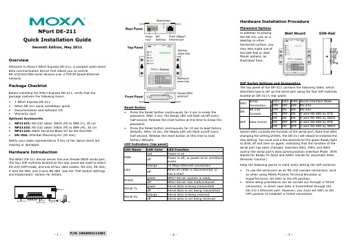
– 1 –– 2 – – 3 –P/N: 1802002112401NPort DE-211 Quick Installation GuideSeventh Edition, May 2011OverviewWelcome to Moxa’s NPort Express DE-211, a compact palm-sized data communication device that allows you to controlRS-232/422/485 serial devices over a TCP/IP based Ethernet network.Package ChecklistBefore installing the NPort Express DE-211, verify that the package contains the following items: • 1 NPort Express DE-211• NPort DE-211 quick installation guide • Documentation and software CD • Warranty cardOptional Accessories• NP21101: RS-232 cable: DB25 (M) to DB9 (F), 30 cm • NP21102: RS-232 cable: DB25 (M) to DB9 (M), 30 cm • NP21103: DB25 Terminal Block Kit for RS-422/485 •DK-35A: DIN-Rail Mounting Kit (35 mm)Notify your sales representative if any of the above items are missing or damaged.Hardware IntroductionThe NPort DE-211 device server has one female DB25 serial port. The four DIP switches located on the rear panel are used to select RS-232 COM mode, and one of four data modes: RS-232, RS-422, 4-wire RS-485, and 2-wire RS-485. See the “DIP Switch Settings and Explanation” section for details.Reset Button •Press the Reset button continuously for 3 sec to erase the password. After 3 sec, the Ready LED will flash on/off every half second. Release the reset button at this time to erase the password.•Press the Reset button continuously for 10 sec to load factory defaults. After 10 sec, the Ready LED will flash on/off every half second. Release the reset button at this time to load factory defaults.Hardware Installation ProcedurePlacement Options In addition to placing the DE-211 unit on a desktop or otherhorizontal surface, you may also make use of the DIN-Rail or Wall Mount options, as illustrated here.Wall MountDIN-RailDIP Switch Settings and ExplanationThe top panel of the DE-211 contains the following table, which describes how to set up the serial port using the four DIP switches located on DE-211’s rear panel.SW1 SerialConnection SW2 SW3 SW4Serial Interface Mode OFF OFF OFF RS-232 ONRS-232 ConsoleOFF ON ON RS-422ON OFF ON 4-wire RS-485 by RTS OFF Data CommON ON ON 4-wire RS-485 by ADDC ON OFF OFF 2-wire RS-485 by RTS ON ON OFF 2-wire RS-485 by ADDCSwitch SW1 controls the function of the serial port. Note that after changing the setting of SW1, the DE-211 will reboot to initialize the new setting. You must wait a few seconds for the green Ready light to blink off and then on again, indicating that the function of the serial port has been changed. Switches SW2, SW3, and SW4control the serial port’s data communication Interface Mode. (RTS stands for Ready To Send and ADDC stands for Automatic Data Direction Control.)Keep the following points in mind when setting the DIP switches: •To use the serial port as an RS-232 console connection, such as when using MOXA PComm Terminal Emulator or HyperTerminal, set SW1 to the ON position.•Some setup procedures can be carried out through a Telnet connection, in which case data is transmitted through the DE-211’s Ethernet port. However, you must set SW1 to the OFF position to establish a Telnet connection.owerPC– 4 – – 5 – – 6 –/supportThe Americas: +1-714-528-6777 (toll-free: 1-888-669-2872)Europe: +49-89-3 70 03 99-0 Asia-Pacific: +886-2-8919-1230China:+86-21-5258-9955 (toll-free: 800-820-5036)2011 Moxa Inc. All rights reserved.Software Installation InformationDetailed information about installing the software that comes with the DE-211 can be found on the NPort Documentation andSoftware CD in the “NPort Family Software Installation Guide”.Pin Assignments and Cable WiringFemale DB25 Connector PinoutsRS-232 WiringRS-422 WiringRS-485 WiringDB25 Terminal Block Kit (RS-422, RS-485-2W/4W)Environmental SpecificationsPower requirements 12 to 30 VDC150 mA (max.) at 12 V92 mA (max.) at 24 VOperating Temp. 0 to 55°C Ambient Relative Humidity 5 to 95% (non-condensing) Dimensions Including ears: 90.2 × 100.4 × 22 mm(3.55 × 3.95 × 0.87 in)Without ears: 67 × 100.4 × 22 mm (2.64 × 3.95 × 0.87 in)Surge Protection 15 KV ESD for the serial port Magnetic Isolation Protection 1.5 KV for the Ethernet port Regulatory Approvals FCC Class B, CE Class B, UL 60950-1, EN 60950-1。
AX PRO系列的无线报警器说明说明书

Appearance1Indicator BuzzerCable Hole Set Screw TamperScrewHoleSwitch2IndicationLED Indication Description Buzzer Armed Operations Green LED flashes 7times.EnrolledRed LED flashes 3times.Formatted Red LED flashes twice.Disarmed Res LED flashes once.Display Signal Strengthindicator turns red for 3s.indicator flashes red for 3s.DisconnectedWeek Signal indicator turns orange for 3s Medium Signal indicator turns green for 3s.Strong Signal Check signal strength and select installation placeEnter the signal checking mode by operating on the AX PRO.Zone Alarm Note:You can sign in web client “Device -Sounder -Settings”or the mobile client “wireless Device”to adjust the volume of buzzer.Two beeps.DisarmedOne beep.ArmedFire bell.Fire Alarm High and low frequemcy alternated impulsive sound.Panic Alarm Rapid high frequency impulsive sound.©2023Hangzhou Hikvision Digital Technology Co.,Ltd.All rights reserved.About this ManualThe Manual includes instructions for using and managing the Product.Pictures,charts,images and all other information hereinafter are for description and explanation only.The information contained in the Manual is subject to change,without notice,due to firmware updates or other reasons.Please find the latest version of this Manual at the Hikvision website (https:///).Please use this Manual with the guidance and assistance of professionals trained in supporting the Product.Trademarksand other Hikvision’s trademarks and logos are the properties of Hikvision in various jurisdictions.Other trademarks and logos mentioned are the properties of their respective owners.DisclaimerTO THE MAXIMUM EXTENT PERMITTED BY APPLICABLE LAW,THIS MANUAL AND THE PRODUCT DESCRIBED,WITH ITS HARDWARE,SOFTWARE AND FIRMWARE,ARE PROVIDED “AS IS”AND “WITH ALL FAULTS AND ERRORS”.HIKVISION MAKES NO WARRANTIES,EXPRESS OR IMPLIED,INCLUDING WITHOUT LIMITATION,MERCHANTABILITY ,SATISFACTORY QUALITY ,OR FITNESS FOR A PARTICULAR PURPOSE.THE USE OF THE PRODUCT BY YOU IS AT YOUR OWN RISK.IN NO EVENT WILL HIKVISION BE LIABLE TO YOU FOR ANY SPECIAL,CONSEQUENTIAL,INCIDENTAL,OR INDIRECT DAMAGES,INCLUDING,AMONG OTHERS,DAMAGES FOR LOSS OF BUSINESS PROFITS,BUSINESS INTERRUPTION,OR LOSS OF DATA,CORRUPTION OF SYSTEMS,OR LOSS OF DOCUMENTATION,WHETHER BASED ON BREACH OF CONTRACT,TORT (INCLUDING NEGLIGENCE),PRODUCT LIABILITY ,OR OTHERWISE,IN CONNECTION WITH THE USE OF THE PRODUCT,EVEN IF HIKVISION HAS BEEN ADVISED OF THE POSSIBILITY OF SUCH DAMAGES OR LOSS.YOU ACKNOWLEDGE THAT THE NATURE OF THE INTERNET PROVIDES FOR INHERENT SECURITY RISKS,AND HIKVISION SHALL NOT TAKE ANY RESPONSIBILITIES FOR ABNORMAL OPERATION,PRIVACY LEAKAGE OR OTHER DAMAGES RESULTING FROM CYBER-ATTACK,HACKER ATTACK,VIRUS INFECTION,OR OTHER INTERNET SECURITY RISKS;HOWEVER,HIKVISION WILL PROVIDE TIMELY TECHNICAL SUPPORT IF REQUIRED.YOU AGREE TO USE THIS PRODUCT IN COMPLIANCE WITH ALL APPLICABLE LAWS,AND YOU ARE SOLELY RESPONSIBLE FOR ENSURING THAT YOUR USE CONFORMS TO THE APPLICABLE LAW.ESPECIALLY ,YOU ARE RESPONSIBLE,FOR USING THIS PRODUCT IN A MANNER THAT DOES NOT INFRINGE ON THE RIGHTS OF THIRD PARTIES,INCLUDING WITHOUT LIMITATION,RIGHTS OF PUBLICITY ,INTELLECTUAL PROPERTY RIGHTS,OR DATA PROTECTION AND OTHER PRIVACY RIGHTS.YOU SHALL NOT USE THIS PRODUCT FOR ANY PROHIBITED END-USES,INCLUDING THE DEVELOPMENT OR PRODUCTION OF WEAPONS OF MASS DESTRUCTION,THE DEVELOPMENT OR PRODUCTION OF CHEMICAL OR BIOLOGICAL WEAPONS,ANY ACTIVITIES IN THE CONTEXT RELATED TO ANY NUCLEAR EXPLOSIVE OR UNSAFE NUCLEAR FUEL-CYCLE,OR IN SUPPORT OF HUMAN RIGHTS ABUSES.IN THE EVENT OF ANY CONFLICTS BETWEEN THIS MANUAL AND THE APPLICABLE LAW,THE LATTER PREVAILS.4Enrollment1.Remove the screw on the bottom of the sounder,and disassemble the peripheral and remove the rear panel..2.Insert the batteries.Note:for re-enrollment,you need to hold the tamper button while powering the peripheral on simultaneously.CAUTIONRISK OF EXPLOSION IF BATTERY IS REPLACED BY AN INCORRECT TYPE.DISPOSE OF USED BATTERIES ACCORDING TO THE INSTRUCTIONS CHEMICAL BURNING DANGER DO NOT SWALLOW THE BATTERY KEEP NEW AND USED BATTERIES AWAY FROM THE CHILDRENEnroll the Peripheral LocallyEnroll the Peripheral with APP1.In the APP ,tap the "Enrollment Mode"button on the control panel page to make the control panel enter the enroll-ment status.2.Push the power switch of the peripheral to on,and it will be automatically enrolled to the control panel.1.In the APP ,tap the icon "+"and scan the QR code on the peripheral or enter the serial No.(Last 5digit)of the peripheral.2.Push the power switch of the peripheral to on,and it will be automatically enrolled to the control panel.3.Log in to the APP Store,download and install App.4.Power on the security control panel.5.Log in the APP and tap the icon "+".Scan the QR code or input the control panel serial No.(Last 5digit)to add the control panel.6.Enroll the peripheral locally,with OR code,or with serial No..INSTALL THE BATTERIES ACCORDING TO THE POLARITY MARK ON THE BATTERY HOLDER.THE OPPOSITE POLARITY MAY CAUSE DEVICEDAMAGE52.Loosen the set screw at the bottom of the sounder and remove the front panel.3.Secure the sounder with other three screws.4.Fix the front panel on the sounder body.Tighten the set screw to complete the installation.1.Check signal strength and select tinstallation placeEnter the signal checking mode by operating on the control panel.Signal indicator turns green for 3s:Strong.Signal indicator turns orange for 3s:Medium.Signal indicator turns red for 3s:Weak.Signal indicator flashes red for 3s:Lost.7Operation8Operation Caution and Device MaintenanceSpecification6FormatingHold the tamper button,and push the power switch to ON simultaneously.Release the tamper button after 8s,and the device will strats formating.While the formating is completed,the red LED flashes 3times.-All the electronic operation should be strictly compliance with the electrical safety regulations,fire prevention regula-tions and other related regulations in your local region.-Do not drop the device or subject it to physical shock,and do not expose it to high electromagnetism radiation.Avoid the equipment installation on vibrations surface or places subject to shock (ignorance can cause equipment damage).-Please make sure that the power has been disconnected before you wire,install or dismantle the device.-If smoke,odors or noise rise from the device,turn off the power at once and unplug the power cable,and then please contact the service center.-Do not drop the device or subject it to physical shock,and do not expose it to high electromagnetism radiation.Avoid the equipment installation on vibrations surface or places subject to shock (ignorance can cause equipment damage).-Do not place the device in extremely hot (refer to the specification of the device for the detailed operation tempera-ture),cold,dusty or damp locations,and do not expose it to high electromagnetic radiation.-The device for indoor use shall be kept from rain and moisture.Exposing the equipment to direct sun light,low ventilation or heat source such as heater or radiator is forbidden (igno-rance can cause fire danger).-Do not aim the device at the sun or extra bright places.A blooming or smear may occur otherwise (which is not a malfunction however),and affecting the endurance of sensor at the same time.-Improper use or replacement of the battery may result in hazard of explosion.Replace with the same or equivalent type only.Dispose of used batteries according to the instructions provided by the battery manufacturer.-Do not expose the device to the corrosive gas.Otherwise the equipment damage may occur.-Do not expose the device to the explosive situation.。
SINUMERIK SINUMERIK 840D sl 前置操作面板:OP 015A 设备手册 06
1.4 1.4.1 1.4.1.1 1.4.1.2 1.4.1.3 1.4.1.4 1.4.2 1.4.2.1 1.4.2.2 1.4.2.3 1.4.2.4 1.4.2.5 1.4.2.6 1.4.2.7 1.4.2.8 1.4.2.9 1.4.2.10
联网................................................................................................................................40 系统设置.........................................................................................................................40 采用 SINUMERIK solution line 时的设置........................................................................40 设备网络中的系统启动....................................................................................................42 精简型客户端单元(TCU)............................................................................................43 出厂预设置......................................................................................................................44 调试 TCU........................................................................................................................46 操作 TCU 主菜单............................................................................................................46 操作其他 TCU 菜单.........................................................................................................49 在设备网络中注册 TCU..................................................................................................61 校准触摸面板..................................................................................................................64 连接 SIMATIC Thin Client 触摸面板...............................................................................66 配置 SIMATIC Thin Client 触摸面板...............................................................................67 文件“config.ini”中的设置...............................................................................................69 文件“tcu.ini”中的设置....................................................................................................72 采用 TCU 时的置换机制.................................................................................................79 通过 PLC 禁止 TCU 之间的切换.....................................................................................81
Moxa NPort W2150A W2250A 系列产品说明书

NPort W2150A/W2250A Series1and2-port serial-to-WiFi(802.11a/b/g/n)device servers with wireless clientFeatures and Benefits•Links serial and Ethernet devices to an IEEE802.11a/b/g/n network•Web-based configuration using built-in Ethernet or WLAN•Enhanced surge protection for serial,LAN,and power•Remote configuration with HTTPS,SSH•Secure data access with WEP,WPA,WPA2•Fast roaming for quick automatic switching between access points•Offline port buffering and serial data log•Dual power inputs(1screw-type power jack,1terminal block)CertificationsIntroductionThe NPort®W2150A and W2250A are the ideal choice for connecting your serial and Ethernet devices,such as PLCs,meters,and sensors,to a wireless LAN.Your communications software will be able to access the serial devices from anywhere over a wireless LAN.Moreover,the wireless device servers require fewer cables and are ideal for applications that involve difficult wiring situations.In Infrastructure Mode or Ad-Hoc Mode,the NPort®W2150A and NPort®W2250A can connect to Wi-Fi networks at offices and factories to allow users to move,or roam,between several APs (access points),and offer an excellent solution for devices that are frequently moved from place to place.SpecificationsEthernet Interface10/100BaseT(X)Ports(RJ45connector)1Magnetic Isolation Protection 1.5kV(built-in)Standards IEEE802.3for10BaseTIEEE802.3u for100BaseT(X)Ethernet Software FeaturesConfiguration Options Web Console(HTTP/HTTPS),Windows UtilityManagement DHCP Option82,HTTP,IPv4,SMTP,SNMPv1/v2c/v3,Syslog,Telnet,Web Console Windows Real COM Drivers Windows95/98/ME/NT/2000,Windows XP/2003/Vista/2008/7/8/8.1/10(x86/x64),Windows2008R2/2012/2012R2(x64),Windows Embedded CE5.0/6.0,Windows XPEmbeddedLinux Real TTY Drivers Kernel versions:2.4.x,2.6.x,3.x,4.x,and5.xFixed TTY Drivers SCO UNIX,SCO OpenServer,UnixWare7,QNX4.25,QNX6,Solaris10,FreeBSD,AIX5.x,HP-UX11i,Mac OS XAndroid API Android3.1.x and laterMIB Device Settings MIB,RFC1213,RFC1317Security HTTPS/SSL,Local Account Accessibility,TACACS+,SSH Time Management NTP Client,SNTP ClientWLAN InterfaceWLAN Standards802.11a/b/g/nReceiver Sensitivity for802.11a(measured at5.680 GHz)Typ.-91@6Mbps Typ.-74@54MbpsReceiver Sensitivity for802.11b(measured at2.437 GHz)Typ.-92dBm@1Mbps Typ.-84dBm@11MbpsReceiver Sensitivity for802.11g(measured at2.437 GHz)Typ.-91dBm@6Mbps Typ.-73dBm@54MbpsReceiver Sensitivity for802.11n(2.4GHz;measured at2.437GHz)Typ.-89dBm@6.5Mbps(20MHz) Typ.-71dBm@72.2Mbps(20MHz)Receiver Sensitivity for802.11n(5GHz;measured at 5.680GHz)Typ.-89dBm@6.5Mbps(20MHz) Typ.-71dBm@72.2Mbps(20MHz) Typ.-85dBm@13.5Mbps(40MHz) Typ.-67dBm@150Mbps(40MHz)Modulation Type DSSSOFDMTransmission Distance Up to100meters(in open areas)Transmission Rate802.11a/g:54Mbps802.11b:11Mbps802.11n:6.5to150MbpsTransmitter Power for802.11b16±1.5dBm@1Mbps16±1.5dBm@11MbpsTransmitter Power for802.11g16±1.5dBm@6Mbps14±1.5dBm@54MbpsTransmitter Power for802.11a15±1.5dBm@6Mbps14±1.5dBm@54MbpsTransmitter Power for802.11n(2.4GHz)16dBm@1.5Mbps(6.5MHz)12dBm@1.5Mbps(72.2MHz)Transmitter Power for802.11n(5GHz)15dBm@1.5Mbps(6.5MHz)12dBm@1.5Mbps(150MHz)Wireless Security WEP encryption(64-bit and128-bit)WPA/WPA2-Enterprise(IEEE802.1X/RADIUS,TKIP,AES)WPA/WPA2-PersonalWLAN Modes Ad-hoc Mode,Infrastructure modeSerial InterfaceConnector DB9maleNo.of Ports NPort W2150A/W2150A-T:1NPort W2250A/W2250A-T:2Serial Standards RS-232,RS-422,RS-485Operation Modes Real COM mode,TCP Server mode,TCP Client mode,UDP mode,RFC2217mode,PairConnection mode,Ethernet Modem mode,DisabledBaudrate50bps to921.6kbpsData Bits5,6,7,8Stop Bits1,1.5,2Parity None,Even,Odd,Space,MarkFlow Control None,RTS/CTS,XON/XOFFRS-485Data Direction Control ADDC®(automatic data direction control)Pull High/Low Resistor for RS-4851kilo-ohm,150kilo-ohmsTerminator for RS-485120ohmsSurge1kVPhysical CharacteristicsHousing MetalInstallation Desktop,DIN-rail mounting(with optional kit),Wall mountingDimensions(with ears,without antenna)77x111x26mm(3.03x4.37x1.02in)Dimensions(without ears or antenna)100x111x26mm(3.94x4.37x1.02in)Weight NPort W2150A/W2150A-T:547g(1.21lb)NPort W2250A/W2250A-T:557g(1.23lb)Antenna Length109.79mm(4.32in)Environmental LimitsOperating Temperature Standard Models:0to55°C(32to131°F)Wide Temp.Models:-40to75°C(-40to167°F)Storage Temperature(package included)-40to75°C(-40to167°F)Ambient Relative Humidity5to95%(non-condensing)Power ParametersInput Current NPort W2150A/W2150A-T:179mA@12VDCNPort W2250A/W2250A-T:200mA@12VDCInput Voltage12to48VDCStandards and CertificationsEMC EN55032/24EMI CISPR32,FCC Part15B Class AEMS IEC61000-4-2ESD:Contact:4kV;Air:8kVIEC61000-4-3RS:80MHz to1GHz:3V/mIEC61000-4-4EFT:Power:2kV;Signal:2kVIEC61000-4-5Surge:Power:2kV;Signal:1kVIEC61000-4-6CS:150kHz to80MHz:3V/m;Signal:3V/mIEC61000-4-8PFMFIEC61000-4-11DIPsRadio Frequency CE(ETSI EN301893,ETSI EN300328,ETSI EN301489-17,ETSI EN301489-1),ARIBRCR STD-33,ARIB STD-66ReliabilityAlert Tools RTC(real-time clock)Automatic Reboot Trigger Built-in WDTMTBFTime NPort W2150A/W2150A-T:383,187hrsNPort W2250A/W2250A-T:363,327hrsStandardsTelcordia (Bellcore)Standard TR/SR WarrantyWarranty Period5years Details See /warrantyPackage ContentsDevice1x NPort W2150A/W2250A Series device server Power Supply1x power adapter,suitable for your region (standard temp.models only)Antenna1x 2.4/5GHz antenna Documentation 1x quick installation guide1x warranty card DimensionsOrdering InformationModel NameNo.of serial ports Serial Standards Baudrate Operating Temp.Input Current Input Voltage NPort W2150A 1RS-232/422/48550bps to 921.6kbps0to 55°C 179mA @12VDC 12-48VDC NPort W2250A 2RS-232/422/48550bps to 921.6kbps0to 55°C 200mA @12VDC 12-48VDC NPort W2150A-T 1RS-232/422/48550bps to 921.6kbps-40to 75°C 179mA @12VDC 12-48VDC NPort W2250A-T 2RS-232/422/48550bps to 921.6kbps -40to 75°C 200mA @12VDC 12-48VDCAccessories(sold separately)AntennasANT-WDB-ARM-02 2.4/5GHz,omni-directional rubber duck antenna,2dBi,RP-SMA(male)CablesCBL-F9M9-150DB9female to DB9male serial cable,1.5mCBL-F9M9-20DB9female to DB9male serial cable,20cmConnectorsADP-RJ458P-DB9F DB9female to RJ45connectorMini DB9F-to-TB DB9female to terminal block connectorDIN-Rail Mounting KitsDK35A DIN-rail mounting kit,35mmPower AdaptersPWR-12050-WPAU-S1Locking barrel plug,12VDC,0.5A,100-240VAC,Australia(AU)plug,0to40°C operating temperature PWR-12050-WPCN-S1Locking barrel plug,12VDC,0.5A,100to240VAC,China(CN)plug,0to40°C operating temperature PWR-12050-WPEU-S1Locking barrel plug,12VDC,0.5A,100-240VAC,Continental Europe(EU)plug,0to40°C operatingtemperaturePWR-12050-WPUK-S1Locking barrel plug,12VDC,0.5A,100-240VAC,United Kingdom(UK)plug,0to40°C operatingtemperaturePWR-12050-WPUSJP-S1Locking barrel plug,12VDC,0.5A,100-240VAC,United States/Japan(US/JP)plug,0to40°Coperating temperaturePWR-12150-AU-SA-T Locking barrel plug,12VDC,1.5A,100-240VAC,Australia(AU)plug,-40to75°C operatingtemperatureApplicable Models:NPort W2150A-TNPort W2250A-TPWR-12150-CN-SA-T Wide-temperature(-40to75°C)locking barrel plug,12VDC,1.5A,100to240VAC,China(CN)plugApplicable Models:NPort W2150A-TNPort W2250A-TPWR-12150-EU-SA-T Locking barrel plug,12VDC,1.5A,100-240VAC,Continental Europe(EU)plug,-40to75°C operatingtemperatureApplicable Models:NPort W2150A-TNPort W2250A-TPWR-12150-UK-SA-T Locking barrel plug,12VDC,1.5A,100-240VAC,United Kingdom(UK)plug,-40to75°C operatingtemperatureApplicable Models:NPort W2150A-TNPort W2250A-TPWR-12150-USJP-SA-T Locking barrel plug,12VDC1.5A,100-240VAC,United States/Japan(US/JP)plug,-40to75°Coperating temperatureApplicable Models:NPort W2150A-TNPort W2250A-TPower CordsCBL-PJ21NOPEN-BK-30Locking barrel plug to bare-wire cable©Moxa Inc.All rights reserved.Updated Nov08,2019.This document and any portion thereof may not be reproduced or used in any manner whatsoever without the express written permission of Moxa Inc.Product specifications subject to change without notice.Visit our website for the most up-to-date product information.。
Edimax Office 1-2-3 吸頂式AP套裝说明书

Office 1-2-3AC1300辦公室專用吸頂式AP(套裝)目錄目錄 (1)I前言 (2)II產品資訊 (3)II-1包裝內容 (3)II-2系統需求 (3)II-3硬體介面 (4)II-4LED狀態 (4)II-5恢復出廠預設值 (5)III安裝設定前注意和準備事項 (6)IV硬體安裝 (9)V軟體設定 (10)VI訪客上網操作說明 (31)VII員工上網操作說明 (33)VIII無線設備上網操作說明 (41)IX Q&A (42)I前言I-1有關完整的Office 1-2-3系統介紹,請參考以下網址:或掃瞄QRcode 。
I-2您可以掃描下面QRcode在網站上找到相關技術文件和程式:/edimax_pro/download/Office1-2-3 (改放繁中載點QRcode )。
I-3您可以掃描QRcode 觀看產品影片介紹:/edimax_pro/download/Office1-2-3 (若該網站不能放繁中影片則改連到Youtube頻道QRcode )。
I-4如果您需要擴大無線網路覆蓋範圍,Office 1-2-3最多可達16台AP的管控能力。
I-5若您的環境需要使用EDIMAX其它機種基地台,它將無法被Office 1-2-3 納管,建議改用APC500搭配其它WAP/CAP/OAP系列AP。
I-6請先參考後續應用情境說明及介紹,並先行備妥相關設定所需資料後依安裝指南的建議進行設定。
I-7在設定過程中,只要點選”啟用”按鈕,即會重新啟動AP,建議您更改完所有設定後再點選”啟用”按鈕。
I-8如安裝設定過程中有任何問題,請就近向原購買經銷商尋求技術協助。
II 產品資訊II-1 包裝內容123 45671. Office1-2-3 無線基地台*3(主控AP*1, 被控AP*2)2. 吸頂安裝組件*33. 網路線*34. 安裝指南*15. T 型導軌安裝組件及螺絲*36. 電源變壓器*37. 吸頂安裝螺絲孔位貼紙*3II-2 系統需求● 可正常連接Internet 的路由器/防火牆(需啟動DHCP Server 功能)。
风电齿轮箱结构设计及齿轮应力分析刍议

风电齿轮箱结构设计及齿轮应力分析刍议陈作越;王小娥;王明清【摘要】就兆瓦级风电增速齿轮箱的结构设计以及齿轮箱齿轮副的接触强度分析提出了相应的设计及解决方案.【期刊名称】《水电与新能源》【年(卷),期】2011(000)002【总页数】4页(P72-75)【关键词】风电齿轮箱;结构设计;有限元接触分析【作者】陈作越;王小娥;王明清【作者单位】乐山职业技术学院,四川,乐山,614000;眉山职业技术学院,四川,眉山,620036;乐山职业技术学院,四川,乐山,614000【正文语种】中文【中图分类】TH132.41以某公司生产的1.65 MW风力发电机(TW1650)为例,主要技术指标:发电机额定功率:1 650 kW齿轮箱额定功率:1 775 kW使用系数KA:1.3齿轮箱传动比:98.74+0/-2额定功率时输入转速:18.23 r/min额定功率时输出转速:1 800 r/min在现实的应用中,兆瓦级风电齿轮箱的传动比一般在100左右。
大致可分两种传动形式:一级行星与两级平行轴圆柱齿轮组合传动;两级行星与一级平行轴圆柱齿轮组合传动。
行星传动相对于平行轴圆柱齿轮传动主要有以下优点:①传动效率较高,体积小,结构简单,制造方便,传递功率范围大,能实现功率分流;②共轴式的传动装置使得轴向尺寸大大缩小;③运动平稳、抗冲击能力强。
行星齿轮传动也存在某些缺点:①其结构形式比定轴齿轮传动复杂;②对制造精度要求较高;③由于体积较小以及散热面积小,导致油温容易升高,所以对润滑与冷却装置的要求比较高。
而上述两种设计方案综合了两者的优点,尽量避免了其缺点。
经过方案对比,采用两级行星传动+高速轴定轴传动的方案。
为了补偿制造误差,行星传动一般采用均载机构,以达到均衡各行星轮的传递载荷,提高齿轮的承载能力以及啮合平稳性的目的,从而降低制造成本。
由于太阳轮的重量轻,惯性小,将它作为均载浮动件时浮动灵敏,结构简单,效果比较显著。
