松下510手册
松下电话交换机TD510常见故障及解决方法
32、 TD510CN如何实现停电转移
TD510CN停电转移,除程序需要编以外,在机器上必须接附助设备
可以,在TD510编程中修改2-7的3/4页中第28项
37、 TD510CN的TD50104卡功能
它是TD510CN会议扩充卡,原TD510CN系统只同时存在8组三方会议,加入这块卡后,系统同时可存在64三方会议
38、 TD510CN错误记录里有E0002和E0006错误它们各代表什么意思
24、 TD510CN怎样在普通话机上提取保留的外线
在普通话机上提取保留外线,保留时只能使用寄存区保留,其他方式不能实现
25、 TD510CN远程话机如何实现
在我们机器中有远程分机板(KX-T96186),但只能接普通分机,可以过到9.6公里
26、 TD510CN用E&M组网怎么样实现等位拨号。有些什么要求?
46、 TD510CNI型机如何关闭KX-T96183CN反极性计费功能?
在编程DUMB方式下,进入PRG模式,输入命令PRD AT 回车,选择外线物理地址,将“Y”改“N”。
47、 TD510CNI型机强插功能证实音怎么取消
在系统程序中Operator(1/3)中的Beep tone Bsy-ovr/Big-in 改为“NO”
要求双方分机字头不同,在数字方案里填入另一个PBX字头。
27、 TD510CN一型机能否实现外线寻线顺序,如连续、正常及由后向前搜索
不行,TD510CN一型机没有这功能,但在我们现在TD510CN二型机有这个功能
松下kx-td510简单编程
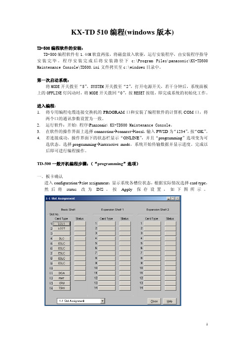
KX-TD 510编程(windows版本)TD-500编程软件的安装:TD-500编程软件有1.44M软盘两张,将磁盘放入软驱,运行安装程序,由安装程序指导安装完毕。
程序安装完成后将安装路径下c:\Program Files\panasonic\KX-TD500 Maintenance Console\TD500.ini文件拷贝至c:\windows目录中。
第一次启动系统:将MODE开关拨至“5”,SYSTEM开关拨至“2”,打开电源开关,若干分钟后,系统面板上的OFFLINE灯闪动时,将MODE开关拨回“0”,按RESET按钮,即完成系统的初始化工作。
进入编程:1.将专用编程电缆连接交换机的PROGRAM口和安装了编程软件的计算机COM口,将两个口的通讯参数设置为一致。
2.运行软件:开始\ 程序\Panasonic\ KX-TD500 Maintenance Console。
3.在软件的操作界面上选择connectionÆconnectÆlocal,输入PWSD为“1234”,按“OK”。
4.若连接成功,操作界面下的状态栏显示“ONLINE”,并且“programming”选项变为可选状态。
选择programmingÆinteractive mode,系统开始传输数据并显示进度。
完成以后即可进行编程操作。
TD-500一般开机编程步骤:(“programming”选项)一.板卡确认进入configurationÆslot assignment:显示系统各槽位状态,根据实际情况选择card type,然后将status改为INS。
按Apply保存设置,如下图所示。
二.中继卡设置进入configurationÆtrunk port assignment:选择中继板Card No,再将中继线分组,status 改为INS,按Apply保存设置。
如下图所示。
松下机器人操作手册

安全开关按下过轻 [力度适中]
伺服电源打开 <可以打开>
安全开关按下力量过大 伺服电源关闭
[力度过大]
<不能打开>
※1 ※2
※3
伺服打开
2 打开 机器人运转 图标 3.选择坐标系
※2 ※3
按下 右转换键 后,可以使用 键切换坐标
关闭
打开
关节
切换
直角
切换
工具
切换
圆柱
用户
(需要使用扩张机能设定)
+
右转换键
<在示教模式下使用用户功能键>
※24
+ 保存
使用这些键 进行换页
F1 F2 F3 F4 F5
开始跟踪 检气・送丝 示教内容切换 追加次序指令 切替 *速度变换 焊接/空走 插补方式变换 坐标系变换 切替
上面的设定仅仅是假设,用户可以根据需要随意改变设定内容。
* 在示教以外的其他操作方式时,功能键的使用会随着操作方式的不同而不同。 如果要了解进一步的详细信息,请参考用户功能键使用说明。
向前微动
微动键
TP正面
液晶显示屏
向后微动
+加
-减
确认/登录键 窗口切换键
(背面) 右转换键
取消键
安全开关
TP背面
右转换键
左转换键
模式选择开关
用户功能键
中文名称 非常停止开关
启动开关 暂停开关 伺服启动开关 Jog 微动键 登录键(确认键) 窗口切换键 取消键 用户功能键 模式选择开关 运动功能键 右转换键 左转换键 3 点安全开关
ファンクションキーⅠ
4.运转 推荐坐标(直角坐标/运动)(工具坐标/角度)
1)各轴运动时坐标系的选择
直角
焊枪的运动
acs510简要操作说明
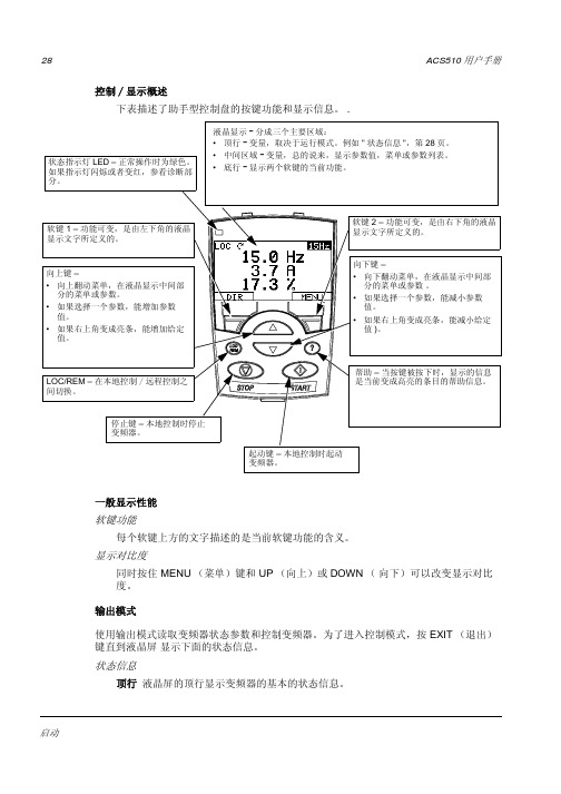
28ACS510 用户手册控制/显示概述下表描述了助手型控制盘的按键功能和显示信息。
.一般显示性能软键功能每个软键上方的文字描述的是当前软键功能的含义。
显示对比度同时按住 MENU (菜单)键和 UP (向上)或DOWN ( 向下)可以改变显示对比度。
输出模式使用输出模式读取变频器状态参数和控制变频器。
为了进入控制模式,按 EXIT (退出) 键直到液晶屏 显示下面的状态信息。
状态信息顶行 液晶屏的顶行显示变频器的基本的状态信息。
LOCDIR12:45MENU400RPM1200 RPM 12.4 A405 dm3/sACS510 用户手册29•LOC (本地) -表示变频器处于本地控制,即控制命令来自控制盘。
•REM (远程) -表示变频器处于远程控制, 例如 I/O (X1) 或现场总线。
•- 显示变频器和电机的旋转状态:•右上角 -显示当前给定。
中间区域 使用参数组 34, 液晶屏的中间区域可选择要显示的内容:•三个参数值。
–缺省设置是显示三个参数值。
0103 (OUTPUTFREQUENCY 输出频率),0104 (CURRENT 电流), 0105 (TORQUE 转矩)。
–使用参数 3401, 3408, 和3415来选择在控制盘上显示的参数(参数组01中的参数)。
如果将参数值定义为 0100,会导致无参数显示。
例如, 3401 = 0100 和 3415 = 0100,那么仅仅由参数3408所定义的参数会显示在控制盘上。
–也可以对每个显示参数进行比例换算。
例如将电机转速转换为传送带的线速度。
参数3402…3405 对参数 3401定义的值进行换算,参数 3409…3412 对参数 3408定义的值进行换算,等等。
•棒图显示取代参数数值显示。
–使用参数 3404, 3411 和 3418进行棒图显示设置。
底行 液晶屏底行显示:•底行两角 -显示两个软键指定的功能变频器的操作LOC/REM – 变频器初次上电时, 处于远控模式(REM),它可由控制端子排X1控制。
松下光电开关手册

1)回归反射型传感器的检测距离和检测物体是对RF-230反射镜的值。
而且,检测距离是反射镜的可设定范围。
传感器可检测0.1m以内的物体。
2)扩散反射型传感器的检测距离是以白色无光泽纸(200×200mm)作为检测物体的。
3)如果装有狭缝透光罩(另售),可以检测3×6mm的物体。
4)如果传感器要在周围温度-15°C以下使用,请与经销商联系。
1c器不附带安装支架,请从另售的传感器安装支架例中选择(3种类型)。
注:1)回归反射型的检测距离是专门对于RF-230反射镜的值。
而且,检测距离是反射镜的可设定范围。
传感器可以检测0.1m以内的物体。
2) NX5系列中备有入光时ON型传感器(带后缀“A”的型号)和遮光时(非入光时)ON 型传感器(带后缀“B”的型号)。
以下型号的产品,若电源断开,输出继电器状态仍与检测物体时相同。
(若电源线断开,输出工作仍可以和检测物体时相同。
)请参阅每个型号的输出工作附件 ·RF-230(反射镜)5m电缆长度型备有5m 长电缆长度型(标准:2m )。
动P-P10%2VA以下起)0~+70°C C500V时m受光器各1 140g性负荷)时)时)。
松下电子产品说明书

Thank you very much for purchasing Panasonic products. Read this Instruction Manual carefully and thoroughly for the correct and optimum use of this product. Kindly keep this manual in a convenient place for quick reference.1INTENDED PRODUCTS FOR CE MARKING● R efer “our web site (/id/pidsx/global)” for the intended products.The models listed under “SPECIFICATIONS” come with CE Marking.As for all other models, please contact our office.● C ontact for CEPanasonic Marketing Europe GmbH Panasonic Testing Center Winsbergring 15, 22525 Hamburg,GermanyNotes: 1) Not incorporated on the thru-beam type sensor emitter.2) It is the power indicator (green: lights up when the power is ON) for the thru-beam type sensor emitter.3)Not incorporated on the basic type sensor.3MOUNTING● T he tightening torque should be0.5N·m or less.● O ptimum sensing is possible whenthe position of the transparentsensing object is set at the centerof the sensor and the reflector.flector, the sensing may be unstable.4WIRING DIAGRAMS±10%±10%Note: The thru-beam type sensor emitter does not incorporate the output.5SENSITIVITY ADJUSTMENTStep 1. T urn the sensitivity adjuster fully counterclock-wise to the minimum sensitivity position, MIN.2.I n the light received condition, turn the sen-sitivity adjuster slowly clockwise and con-firm the point A where the sensor entersthe “Light” state operation.3. I n the dark condition, turn the sensitivity adjuster further clockwise until the sensor en-ters the “Light” state operation and then bring it back to confirm point B where the sensor just returns to the “Dark” state operation.If the sensor does not enter the “Light” state operation even when the sensitivity adjuster is turned fully clockwise, the position is point B .4. T he position at the middle of points A and B is the optimum sensing position.6CAUTIONS● T his product has been developed / produced for industrial use only.● M ake sure to carry out wiring in the power supply OFF condition. ● T ake care that wrong wiring will damage the sensor. ● V erify that the supply voltage variation is within the rating. ● I f power is supplied from a commercial switching regula-tor, ensure that the frame ground (F.G.) terminal of the power supply is connected to an actual ground. ● I n case noise generating equipment (switching regulator, inverter motor, etc.) is used in the vicinity of this product, connect the frame ground (F.G.) terminal of the equipment to an actual ground. ● E xtension up to total 100m (each emitter and receiver of th-ru-beam type), or less, is possible with 0.3mm 2, or more of conductor area cable. However , the extension of a power supply line and the output line of less than 10m is accept-able in case using this product as conforming to S-mark. ● M ake sure that stress by forcible bend or pulling is not applied directly to the sensor cable joint. ● D o not run the wires together with high-voltage lines or power lines or put them in the same raceway. This can cause malfunction due to induction. ● D o not use during the initial transient time (50ms) after the power supply is switched ON. ● T ake care that the sensor is not directly exposed to fluorescent lamp from a rapid-starter lamp, a high frequency lighting de-vice or sunlight etc., as it may affect the sensing performance. ● T his sensor is suitable for indoor use only. ● D o not use this sensor in places having excessive vapor, dust, etc., or where it may come in contact with corrosive gas, etc. ● T ake care that the sensor does not come in contact with oil, grease, organic solvents such as thinner, etc., strong acid, or alkaline. ● T his sensor cannot be used in an environment contain-ing inflammable or explosive gases. ● N ever disassemble or modify the sensor.7RoHS DIRECTIVE● T his equipment complies with RoHS (EC and Chinese directive). ● C hinese RoHS indicates inclusion despite regulation value. (Refer Chinese part.)/id/pidsx/globalOverseas Sales Division (Head Office)2431-1 Ushiyama-cho, Kasugai-shi, Aichi, 486-0901, Japan Phone: +81-568-33-7861 FAX: +81-568-33-8591For sales network, please visit our website.© Panasonic Industrial Devices SUNX Co., Ltd. 2016PRINTED IN JAPAN056 222 38 18*********************SEN TRONIC AG。
510变频器文本文档
510变频器文本文档.txt铁饭碗的真实含义不是在一个地方吃一辈子饭,而是一辈子到哪儿都有饭吃。
就算是一坨屎,也有遇见屎壳郎的那天。
所以你大可不必为今天的自己有太多担忧。
输入电压:三相AC380V~480V(频率:50/60Hz;价格不含控制盘;防护等级IP21)Square Torque FrameCode No. Type 平方转矩应用Size产品代号产品型号PN(kW )I2N(A )规格电机额定功率额定输出电流3ABD00015741-D ACS510-01-03A3-4 1.1 3.3 R13ABD00015742-D ACS510-01-04A1-4 1.5 4.13ABD00015743-D ACS510-01-05A6-4 2.2 5.63ABD00015744-D ACS510-01-07A2-4 3 7.23ABD00015745-D ACS510-01-09A4-4 4 9.43ABD00015746-D ACS510-01-012A-4 5.5 11.93ABD00015747-D ACS510-01-017A-4 7.5 17 R23ABD00015748-D ACS510-01-025A-4 11 253ABD00015749-D ACS510-01-031A-4 15 31 R33ABD00015750-D ACS510-01-038A-4 18.5 383ABD00021615-D ACS510-01-046A-4 22 463ABD00015752-D ACS510-01-060A-4 30 60 R43ABD00015753-D ACS510-01-072A-4 37 723ABD00021616-D ACS510-01-088A-4 45 883ABD00019055-D ACS510-01-125A-4 55 125 R53ABD00015756-D ACS510-01-157A-4 75 157 R63ABD00015757-D ACS510-01-180A-4 90 1803ABD00015758-D ACS510-01-195A-4 110 2053ABD00022031-D ACS510-01-246A-4 132 2453ABD00027039-D ACS510-01-290A-4 160 290输入电压:三相AC380V~480V(频率:50/60Hz;价格不含控制盘;防护等级IP54)Square Torque FrameCode No. Type 平方转矩应用Size产品代号产品型号PN(kW) I2N(A)规格电机额定功率额定输出电流3ABD00015759-D ACS510-01-03A3-4+B055 1.1 3.3 R13ABD00015760-D ACS510-01-04A1-4+B055 1.5 4.13ABD00015761-D ACS510-01-05A6-4+B055 2.2 5.63ABD00015762-D ACS510-01-07A2-4+B055 3 7.23ABD00015763-D ACS510-01-09A4-4+B055 4 9.43ABD00015764-D ACS510-01-012A-4+B055 5.5 11.93ABD00015765-D ACS510-01-017A-4+B055 7.5 17 R23ABD00015766-D ACS510-01-025A-4+B055 11 253ABD00015767-D ACS510-01-031A-4+B055 15 31 R33ABD00015768-D ACS510-01-038A-4+B055 18.5 383ABD00021617-D ACS510-01-046A-4+B055 22 463ABD00015770-D ACS510-01-060A-4+B055 30 60 R43ABD00015771-D ACS510-01-072A-4+B055 37 723ABD00021618-D ACS510-01-088A-4+B055 45 883ABD00019056-D ACS510-01-125A-4+B055 55 125 R53ABD00015774-D ACS510-01-157A-4+B055 75 157 R63ABD00015775-D ACS510-01-180A-4+B055 90 1803ABD00015776-D ACS510-01-195A-4+B055 110 2053ABD00022032-D ACS510-01-246A-4+B055 132 2453ABD00027042-D ACS510-01-290A-4+B055 160 290Code No. Option Name Type产品代号可选项名称产品型号3ABD64739000 基本控制盘 Basic Control Panel ACS-CP-C3ABD68232902 高级中文控制盘 Assistant Control Panel for Asia ACS-CP-D3ABD68294673 螺钉式控制盘安装组件;含一根3米长电缆,一个密封垫,固定螺钉和安装模板ACS/H-CP-EXT3ABD0000013086 控制盘安装套件;含一根3米长电缆,可插拔面板的安装支架OPMP-013ABD00014656 托架式控制盘安装组件;含一根3米长电缆,一个塑料固定托架ACS/H-CP-CABINET3ABD68300029 控制盘3米连线OCAT-023AUA0000002040-D 继电器输出扩展模块 Relay Output ExtensionOREL-013AUA0000003489-D (110/230V)/24V数字输入转换模块OHDI-01制动斩波器(外装)和制动电阻 Brake Chopper(separate kit) and Brake Resistor3ABD00017551 法兰安装件用于R1 Flange Mounting Set, R1 FMS-R13ABD00017550 法兰安装件用于R2 Flange Mounting Set, R2 FMS-R23ABD00017549 法兰安装件用于R3 Flange Mounting Set, R3 FMS-R33ABD00017548 法兰安装件用于R4 Flange Mounting Set, R4 FMS-R43ABD00017552 法兰安装件用于R5 Flange Mounting Set, R5 FMS-R53ABD00017553 法兰安装件用于R6 Flange Mounting Set, R6 FMS-R6输出滤波器 du/dt FilterType Output Choke Price(RMB)产品型号输出滤波器型号价格(元) ACS510-01-03A3-4 NOCH0016-6XACS510-01-04A1-4ACS510-01-05A6-4ACS510-01-07A2-4ACS510-01-09A4-4ACS510-01-012A-4ACS510-01-017A-4ACS510-01-025A-4 NOCH0030-6XACS510-01-031A-4 参见ACS510-01-038A-4 ACS800可选项ACS510-01-046A-4 NOCH0070-6XACS510-01-060A-4ACS510-01-072A-4ACS510-01-088A-4ACS510-01-125A-4 NOCH0120-6XACS510-01-157A-4 FOCH0260-70ACS510-01-180A-4ACS510-01-195A-4ACS510-01-246A-4ACS510-01-290A-4 FOCH0320-50。
松下电工自动对位视觉系统使用手册
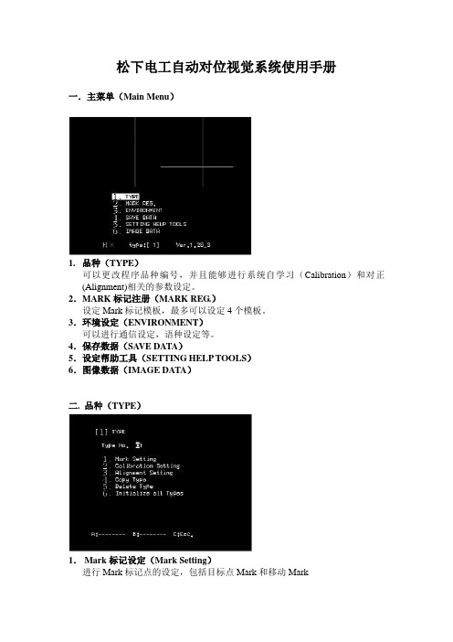
松下电工自动对位视觉系统使用手册一.主菜单(Main Menu)1.品种(TYPE)可以更改程序品种编号,并且能够进行系统自学习(Calibration)和对正(Alignment)相关的参数设定。
2.MARK标记注册(MARK REG.)设定Mark标记模板,最多可以设定4个模板。
3.环境设定(ENVIRONMENT)可以进行通信设定,语种设定等。
4.保存数据(SA VE DATA)5.设定帮助工具(SETTING HELP TOOLS)6.图像数据(IMAGE DATA)二. 品种(TYPE)1.Mark标记设定(Mark Setting)进行Mark标记点的设定,包括目标点Mark和移动Mark2.自学习设定(Calibration Setting)进行自学习过程的指定参数的设定。
3.自动对位设定(Alignment Setting)进行自动对位过程的指定参数的设定。
4.复制品种(Copy Type)5.删除品种(Delete Type)6.初始化所有品种(Initialize all Types)可以恢复本体到出厂时的设置,所有设定的参数和图像将全部丢失。
[1] Mark标记设定(Mark Setting)1.目标Mark点的指定(An applicable mark)A 摄像机(A Camera)对应3号Mark模板B 摄像机(B Camera)对应4号Mark模板2.移动Mark点的指定(Movement mark)A 摄像机(A Camera)对应1号Mark模板B 摄像机(B Camera)对应2号Mark模板3.自动对位的方式选择(Position Setting)对位到固定的屏幕中心点(Screen center fixation)对位到检测到的位置点(A position markdetection)[2] 自学习设定(Calibration Setting)1.自学习的移动量(The amount of movement)可以对X,Y,θ的指定移动距离和角度分别进行设定,距离的单位是mm, 角度的单位是度。
Panasonic KX-TD510CN数字超级混合系统 功能手册

KX-TD510CNPanasonic KX-TD510CN RR引言引言关于本功能手册本功能手册计划用做Panasonic® KX-TD510CN数字超级混合系统的全部功能参考。
本功能手册介绍了KX-TD510CN系统的许多功能以及如何最大限度地利用这些功能。
第一部分,一般功能提供关于一般功能的详细说明。
第二部分,ISDN功能提供关于使用公共转换电话网络ISDN业务所需功能的详细说明。
第三部分,专用网络功能提供关于使用TIE线和VPN(虚拟专用网)业务所需功能的详细说明。
第四部分,音频/振铃音提供音频和振铃音的一览表。
第五部分,索引提供功能标题,主要词汇和段落,帮助你方便地进入所需信息。
全篇手册中可能会使用“他”或“她”、“他的”或“她的”这些词语。
为了提高可读性而不连续使用他/她,我们只用这些词语中的一种。
词语“他”或“她”应视为可互换使用。
本功能手册中使用的术语安装手册参考在安装手册中介绍的所需要的安装说明标题做了标记,供您参考。
2功能手册引言功能手册3编程手册参考在编程手册中介绍的有关和所需的编程标题已做标记,供您参考。
系统编程系统编程应该用一台PC 来完成。
功能手册参考在此功能手册 中介绍的有关功能标题做了标记,供您参考。
用户手册参考对执行在用户手册中介绍的功能所需要的操作做了标记,供您参考。
关于其他手册以下手册与此功能手册一起有助于你安装,编程和使用KX-TD510CN 系统:安装手册提供安装硬件和系统维护的说明。
编程手册提供使用一台PC 的保养控制台软件进行系统编程的逐步说明。
用户手册提供用户使用功能电话(PT)、单线电话(SLT)或DSS 控制台的操作说明。
目录目录1 一般功能 (9)1.1 系统扩充 (10)附加设备端口(XDP) (10)1.2 系统管理 (11)用个人电脑进行系统编程和诊断 (11)话务量测量 (13)用功能电话进行用户编程 (14)1.3 系统功能 (15)计费代码输入 (15)自动呼叫取消 (17)自动配置 (18)背景音乐(BGM)-外部 (19)预算管理 (20)主叫方控制(CPC)信号检测 (22)收费参考 (23)服务等级(COS) (24)拨号类型选择 (26)DIL 1:N群 (27)开门器 (28)E1载波 (29)分机群 (30)外部调制解调器控制 (33)灵活编号 (35)浮动用户电话 (40)主PBX接入 (42)宾馆应用 (43)综合,自动值机员(AA)服务 (49)综合,DPT (52)综合,带内 (55)综合,语音邮件(VM)服务 (58)综合,VPS (64)限制通话时间 (66)锁定 (68)管理员分机 (69)混合用户电话功能 (71)持机音乐 (73)夜间服务 (75)楼外分机(OPX) (77)话务员群 (78)去话留言(OGM) (82)去话留言(OGM)群 (84)并联电话 (85)PC 控制台 (87)幻像分机 (89)解除链接操作 (91)远程用户电话功能控制 (92)4功能手册目录远程用户电话锁定控制 (94)保密拨号 (95)用户电话信息详细记录(SMDR) (96)系统数据缺省值设定 (101)T1载波 (102)用户服务 (104)超时,可变 (106)中继线置忙 (109)中继线群 (113)中继线路由控制 (115)移动用户电话 (116)1.4 故障恢复/诊断 (117)当地告警 (117)电源故障重新启动 (120)电源故障转移 (121)1.5 有人值守功能 (122)发话人ID服务 (122)直接进入线路(DIL) (124)直接向内拨号(DID) (127)直接向内系统接入(DISA) (130)振铃群 (136)中继线从任何用户电话上应答(TAFAS) (138)均匀呼叫分配(UCD) (140)1.6 始发功能 (151)交替呼叫-振铃/语音 (151)占线自动回叫(保持呼叫) (153)路由自动选择(ARS) (154)占线用户电话信令(BSS) (160)免打扰(DND)占优插入 (162)用户电话电子锁定 (163)紧急呼叫 (164)执行占线占优插入 (165)局间呼叫 (167)线路优先—去话(空闲线/无线/主线) (169)摘机呼叫通知(OHCA) (171)摘机呼叫通知(OHCA),耳语 (173)话务员呼叫 (175)PDN(一级号码簿号码)呼叫 (177)长途限制 (178)长途限制 (178)特殊载波接入的长途限制 (186)用计费代码输入长途限制占优插入 (187)系统速拨长途限制占优插入 (189)中继线接入 (190)中继线连接分配-去话 (194)1.7 拨号功能 (197)用户电话自动释放 (197)完全单触拨号 (198)单触拨号 (199)功能手册5目录暂停插入,自动 (201)转接拨号(热线) (202)快速拨号 (204)重拨 (205)重拨,自动 (207)用户电话速拨 (208)系统速拨 (209)1.8 振铃功能 (210)免打扰(DND) (210)注册/注销 (212)用户电话寻线 (214)定时提示器(唤醒呼叫) (216)定时提示器,远程(唤醒呼叫) (218)1.9 应答功能 (220)应答键和释放键操作 (220)应答,直接中继线 (222)呼叫转接 (223)呼叫等待 (226)来自中心局的呼叫等待 (228)拒绝执行占线占优插入 (229)免提应答 (230)线路优先—来话(无线/主线/振铃线) (231)现场呼叫屏蔽(LCS) (233)1.10 保持功能 (235)自动保持-保持用 (235)自动保持-转移用 (236)呼叫保持 (238)呼叫暂停 (240)呼叫分离 (241)协商保持 (242)1.11 转移功能 (244)呼叫转送 (244)呼叫转移 (248)截接路由 (251)单触转移 (252)振铃转移 (254)1.12 通话功能 (255)会议,3方 (255)会议,5方 (257)会议,无人值守 (259)数据线路安全 (261)门电话呼叫 (262)端到端DTMF信令(信号音通过) (263)外部功能接入 (264)闪断 (266)免提操作 (267)摘机监听 (268)保密释放 (269)保密,自动 (270)6功能手册目录脉冲转换至音频 (271)双向录入语音邮件 (272)1.13 可听音功能 (273)证实音 (273)拨号音,特殊的 (275)保持重呼 (277)振铃音选择 (279)振铃,延迟 (280)振铃,辨别 (281)1.14 寻呼功能 (282)寻呼 (282)1.15 功能电话功能 (285)背景音乐(BGM) (285)DSS控制台 (287)手机/头戴送受话器选择 (290)手机麦克风静音 (291)麦克风静音 (292)用户电话程序清除 (293)用户电话编程 (295)用户电话编程数据缺省值设定 (297)音量控制-扬声器/手持受话器/头戴送受话器/振铃器 (298)1.16 键功能 (299)键,直接选台(DSS) (299)键,灵活的 (300)键,线路接入 (303)功能电话和DSS控制台上的键 (307)LED指示 (313)1.17 显示功能 (317)缺席留言功能 (317)双语显示 (319)占线灯区 (320)电话号码簿 (321)呼叫转送/免打扰 (323)呼叫记录,来话 (324)呼叫记录,去话 (327)显示器对比度调节 (328)显示,呼叫信息 (329)显示,日期和时间 (331)显示,自身分机号码 (332)宾馆服务 (333)留言待取 (334)特殊显示功能 (336)系统功能接入菜单 (338)2 ISDN 功能 (341)2.1 ISDN 功能 (342)综合业务数字网(ISDN) (342)综合业务数字网(ISDN)分机 (345)2.2 ISDN(综合业务数字网)始发功能 (347)功能手册7目录呼叫线路识别显示(CLIP) (347)呼叫线路识别限制(CLIR) (349)ISDN网络服务接入 (350)2.3 ISDN应答功能 (351)连接线路识别显示(COLP) (351)连接线路识别限制(COLR) (353)恶意呼叫识别(MCID) (355)2.4 ISDN有人值守功能 (356)直接拨入(DDI) (356)多用户号码(MSN)振铃服务 (359)2.5 ISDN转移功能 (362)用ISDN线路进行呼叫转送 (362)3 专用网络功能 (363)3.1 TIE线路功能 (364)外线(CO)和TIE线路的连接 (364)TIE线路与外(CO)线连接 (366)TIE线路和TIE线路连接 (369)TIE线路网络-迂回路由 (372)TIE线服务 (375)3.2 VPN功能 (382)虚拟专用网(VPN) (382)3.3 网络服务功能 (386)呼叫线路识别显示(CLIP) (386)呼叫线路识别限制(CLIR) (389)连接线路识别显示(COLP) (390)连接线路识别限制(COLR) (393)4 信号音 / 振铃音 (395)5 索引 (403)8功能手册一般功能第一部分一般功能功能手册9一般功能1.1 系统扩充附加设备端口(XDP)说明可接在同一分机端口上的数字功能电话(DPT)和单线电话(SLT)却有两个不同的分机号码,故此它们可作为完全不同的两个分机使用。
松下座机电话说明书

控制键位置座机子机子机软键当软键上部无功能名出现时,软键没有使用。
子机导航键向上[▲]和向下[▼]翻功能菜单、主叫用户名录和电话簿。
增加[▲]或减小[▼]子机铃声和受话器/ 扬声器音量。
编程指南本话机有编程功能,可从显示屏上的功能菜单进行选择(12 页)。
如何从菜单中选择功能选项确保子机和座机处于待机状态。
必须靠近座机在脱离座机时操作子机。
1 按[菜单]键。
显示主菜单(12页)。
2 按[▲]或[▼]键翻至想要的选项。
3 按select(选择)键选择想要的选项。
4 如果该选项有子菜单,就选择菜单选项(12页)。
重复步骤2和步骤3直到显示想要的选项。
如果该选项没有子菜单,就转到步骤5。
5 按[▲]或[▼]键选择想要的设定,接着按save(保存)键以保存您的设定。
会听到一个确认音,并且设定被保存。
6 按[关闭]键退出编程模式。
(1)要回到前一菜单,按back (返回)键或在显示"---(go back)----"时按select (选择)键。
如果您在主菜单中按这一键,话机就会退出编程模式。
(2)在编程完成后,显示将返回至主菜单或子菜单,这取决于所选择的选项位于哪一个菜单。
(参见第12页的菜单表。
)(3)您可以按[关闭]键,随时退出编程模式。
(4)如果在60 秒内仍未按任何键,子机将退出编程模式。
(5)如果话机检测到故障,就会显示一个错误信息(42页)并且/或者发出错误蜂鸣声。
铃声音调您可以设定子机铃声使用7 种振铃方式中的一种用于外线来电。
“tone 1(音调1)”至“tone 3(音调3)”为铃声方式。
“melody 1(曲调1)”至“melody 4(曲调4)”为曲调方式。
出厂时预定为“tone 1(音调1)”。
如果您选择一种曲调铃声方式,在以下情况下,铃声将继续响几秒钟:1 主叫用户在您应答来电前挂断电话,或2 另一个人用连接在同一线路上的其他电话应答来电。
1 按[菜单]键。
Plantronics Voyager 510 USB Bluetooth 头戴式耳机用户指南说明书

Plantronics VoYaGEr ™ 510-UsBBLUETOOTH ® HEADSET SySTEmUSER GUIDEPACKAGE CONTENTSHeadset (front and side view) PerSonoCall® software CD WELCOMEThis User Guide provides instructions on the setup and usage of the Plantronics Voyager 510 USB Bluetooth headset system. Before getting started, please review the safety booklet included in your package. For additional help, service or support information, refer to the product warranty card or visit .FEATURES CHARGINGHorizontal boom adjustmentCall control buttonCharge connectionNoise-cancelling microphone with WindSmart® technology USB chargingStatus indicator lightPAIRINGPowering headsetPairing headset with Bluetooth phoneon or off.The indicator light flashes blue when the headset is on. The indicator light will flash red when PAIRINGPairing headsetNOTE: The headset and USB Bluetooth adapter are paired to each other at the factory. However, if you have purchased a USB Bluetooth adapter separately, or if you wish to use a replacement headset with your existing adapter, the units must be paired.INSTALLING PERSONOCALL ® SOFTWAREPlantronics PerSonoCall ® software provides the link between your Bluetooth headset and compatible softphone applications on your computer. PerSonoCall software provides the ability to remotely detect and answer/end a call from your softphone application via the headset call control button.In addition, PerSonoCall provides some basic configuration and status information about the system. See page 10 for more details.Check the PerSonoCall compatibility list at /personocall for the most current information on softphone compatibility. If your softphone is not currently supported by PerSonoCall, please refer to page 14.1. With the CD inserted, go to the PerSonoCall main screen and click on “Install the PerSonoCall Software”.: No headset detected : Headset detected, no radio link to USB Bluetooth adapter : Headset detected and radio link to USB Bluetooth adapter active : Headset detected and radio link to USB Bluetooth adapter is locked onCurrent Status screen INSTALLING PERSONOCALL SOFTWARERight-click on the headset system tray icon and choose “Options”. This will bring up the PerSonoCall Basic Options and Current Status screens.Basic Options screenReplacing the ear tipRotate the microphone horizontally and vertically as illustrated, to select for left or right ear wearing. The illustration shows conversion from right to left ear wearing. Reverse the procedure to convert from left to right ear wearing.Slide the headset over and behind your ear. Press gently towards your ear for a snug fit. Adjust the microphone position so that it is directed towards your mouth.Inserting a new ear tipADJUSTING FITWearing the headsetTo make a call , press the call control button to take the softphone off the hook. You should hear a dial tone.To answer or end a call , press the call control button.When using PerSonoCall, the radio link between the headset and the USB Bluetooth adapter will only be active during a call. This is the default setting intended to preserve the battery life of the headset. However, you may wish to have the radio link active when not on a call so you can listen to other audio sources, such as streaming audio on your PC. You can lock the radio link on in two ways:• Basic Options screen—check the box for "Lock headset radio link on"—see page 10.• Right click on system tray icon—and choose "Lock radio link on".NOTE: Locking the radio link on for extended periods of time will significantly reduce the USING YOUR HEADSETAdditional featuresOnly with mobile phoneAnswering/ending/making calls with PerSonoCall on softphoneRedialling last numberTo activate last number redial, double-click the call control button. You will Switching a call from phone to headset To switch an active call from your phone to your headset, briefly press the call The Voyager 510-USB headset has multipoint technology which allows you to switch seamlessly between two audio devices. You can answer a call from either your PC-based softphone or your mobile phone by pressing the call control button. The headset must be paired to both devices and then to enable this functionality, see "Allow call control button to toggle the headset’s radio link" on the Basic Options screen on page 10.Multipoint versatilityINDICATOR LIGHTSBluetooth device Connected to headset Flashes blue USING YOUR HEADSETTo adjust the listen or speak volume of the softphone, please refer to the softphone user documentation.TROUBLESHOOTING FOR VOYAGER 510-USB• Lower the listen volume on your softphone until the distortion disappears.• If the distortion is still present, lower the listen volume control on the computer.• Adjust volume on headset. See page 16.• Speak volume is too high. Lower the speak volume on your softphone until the noise disappears. If the noise is still present, lower the microphone volume control on the computer.Sound in headset is distorted. I can hear echo in headset.I can hear too much background conversation or noise.• Check compatibility list on / personocall to ensure your softphone is compatible for remote answer and disconnect.• Headset battery needs to be charged. See page 5.• Headset is not paired to the USB Bluetooth adapter. See page 8.• When a PC goes into standby or hibernation, the USB Bluetooth adapter is no longer powered on. Ensure your PC is in an active state.• Ensure PerSonoCall software is installed My Voyager headset does not work with the softphone I am using on my PC (I cannot answer or disconnect from the headset call button).ProblemSolutionProblemSolutionTECHNICAL ASSISTANCEVisit our web site at /support for technical support including frequently asked questions, compatibility and accessibility information. The Plantronics Technical Assistance Center (TAC) is also ready to assist you on 0800 410 014.Plantronics Ltd Wootton Bassett, UK Tel: 0800 410 014Plantronics B.V. Hoofddorp, Nederland Tel: 0800 752 6876 (NL) 00800 752 687 66 (BE/LUX)Plantronics Sarl Noisy-le-Grand, France Plantronics Acoustics Italia Srl Milano, Italia Numero Verde: 800 950 934Plantronics Iberia, S.L. Madrid, España Tel: 902 415 191 +34 91 640 47 44 (ES) Tel: 800 844 517 (PT)。
CM510_user_guide
建议您在此环境下使用该设备:温度:0℃-35℃。湿度:10%- 90%。
建议您在此环境下保存该设备:温度:-10℃-55℃。湿度: 5%-95%。
产品概述
本产品定位为一款LTE高速4G热点产品。可以方便地为多台终端 设备提供安全的网络共享服务。
WEP 128位开放:安全性较低。一些旧的路由器会选择使用这种方 式。只有在设备不支持WPA或WPA2时才推荐使用。开放式密码一 般只用于加密而不用于授权。HEX格式密码长度26位。
WPA个人TKIP加密:安全性较高。大部分无线设备均支持这种方式。 ASCII格式密码长度8 到63 位。
WPA2个人AES加密: 安全性很高。较新的安全加密方式,只有比较 新的无线设备才支持。ASCII格式密码长度8 到63 位。
在WiFi功能开启状态下长按(3秒以上)
3
WPS/WIFI 按键
激活WPS短按(小于2秒)开启/关 闭。
WiFi功能(需要进行二次确认)。
4
(U)SIM卡 插槽
用于用户插入(U)SIM卡
5
复位按键
短按(小于 2 秒)设备重启, 长按(大于5秒)恢复出厂设置
6
Micro USB 接口
用于设备充电,连接PC机或便携式电 脑
安全设置:
这个部分您可以进行无线网络安全设置。在下面列表中选择一种加 密方式并设置密码。若选择“无”禁用这个功能,任何无线客户端 都可以不用密码直接连接到您的无线网络。
WEP 64位共享:安全性最低。一些旧的路由器会选择使用这种方式。 只有在设备不支持WPA或WPA2时才推荐使用。共享方式加密和授 权使用同一个密码安全性比开放式更低。HEX格式密码长度10位。
DNV510变频器简易使用指导手册
递恩电气技术DNV510系列使用指导手册第一章:变频器选型和控制电路第二章:变频器常用功能使用指导第三章:变频器常见故障及处理措施第二章:变频器常用功能使用指导Ⅱ-1:变频器矢量控制电机参数自学习步骤1.恢复变频器参数到出厂值设置:设置PP.01参数为001,按ENTER确认。
2.按照电机铭牌输入电机参数P1.01—P1.05,如图所示:电机7.5KW设置P1.01=7.5KW,P1.02=380V,P1.03=15A,P1.04=50HZ,P1.05=2900r/min选择电机自学习方式:P1.37=01异步电机静止自学习,适用于异步电机和负载不易脱开情况下,P1.37=02异步电机完全自学习,此时电机必须和负载脱开,电机空轴运行,在此,大多数情况我们选择P1.37=01.3.选择P1.37=1,按ENTER确认键,再按RUN运行键,变频器自动进行电机自学习状态,此时可听见电机吱吱的声音,当变频器自学习完成后,进入待机状态,此时用户方可对变频器进行操作,修改其他参数。
Ⅱ-2:变频器外部电位器调速,外部按钮启停控制电气控制接线图功能参数设定P0.02 运行方式选择 1P0.03 主频率设定 2Ⅱ-3:变频器多段速调速(变频器上电面板电位器可调,外部端子DI4给定一段速度30HZ,DI5给定50HZ)电气控制接线图功能参数设定P0.02 运行方式选择 1P0.03 主频率设定 6P4.03 DI4端子定义12P4.04 DI5端子定义13PC.01 一段速度给定值60%PC.02 二段速度给定值100%PC.51 0段速度给定方式 3备注:当变频器上电后,一段速开关KM1和二段速开关KM2都处在断开状态,此时按下SB1变频器运行,变频器频率由PC.51指定键盘面板旋钮调节频率(0-50HZ可调),当一段速开关KM1闭合,变频器以30HZ固定运行,当二段速开关KM2闭合,变频器以50HZ固定频率运转.Ⅱ-4:变频器PID恒压供水(外接远程压力表0-10V作为反馈,压力表量程1MPa,恒定压力0.2MPa)电气控制接线图功能参数设定P0.02 运行方式选择 1P0.03 主频率设定8P8.49 休眠唤醒频率25HZ P8.50 唤醒延时时间1S P8.51 休眠频率20HZ P8.52 休眠延时时间5S PA.00 PID给定方式0 PA.01 PID压力给定值20% PA.02 PID反馈选择0 PA.04 PID反馈量程1000 PA.05 PID比例增益40 PA.06 PID积分增益 2.5 PA.09 PID压力偏差1%备注:P8.49-P8.51应用于PID恒压供水休眠和唤醒功能。
testo_510_IM_CNpdf

testo 510压差仪(0 ... 100hPa )操作手册testo 510简明手册 ..................................................................................................................................................................1 安全与环保 ..............................................................................................................................................................................2 规格 .........................................................................................................................................................................................3 产品描述 ..................................................................................................................................................................................4 初始步骤 ..................................................................................................................................................................................4 仪器操作 ..................................................................................................................................................................................5 仪器保养和维护 .......................................................................................................................................................................7 提示和帮助 (7)德图质量保障为确保客户享受完善的产品售后维修服务,所有的中国境内由德图和德图授权的代理商出售的德图产品,都会在数据库中录入相应的序列号(SN),客户可以在仪器的包装盒或仪器的电池盒上找到该序列号。
LUM-510-PTZ 510 系列数字 PTZ 摄像头快速使用指南说明书

LUM-510-PTZ Analog Surveillance Camera Quick Start Guide2510 Series Analog PTZ CameraInspectionEnsure that the device is in good condition and all the assembly parts are included. If the product does not function properly, please contact technical support. Do not disassemble the camera for repair or maintenance.Box Contents}Camera with arm mount}24V AC power adapter with two wire leads}Steel cable lanyard with two carabiners}Mount coupling with lanyard hook}Hex wrench}4 expansion screwsRequired EquipmentTo install this camera, you must provide}Small slot-head screwdriver}CC-TV tester (recommended)Preparation}Ensure that your recorder has the very latest firmware. Use OvrC to update thefirmware, or consult your DVR manual.}Make sure that all equipment is powered off during installation.}Ensure the wall is strong enough to withstand three times the weight of the camera and the mount.We recommend installing with RG-59 or RG-6 cabling with two-wire power (thepower supply is included). This provides better performance over distance thantraditional category cable with baluns.3510 Series Analog PTZ CameraBefore installing, familiarize yourself with the parts of your camera.TailsThe PTZ camera has four different tails.BNC Video CablesTwo black BNC cables are labeled for TVI, CVI, CVBS and AHD. These connectors are also provided with protective sheaths to prevent accidental cross-connection. Power CableThe power cable ends in a red screw terminal. Insert the two wires of the power supply into the red and black inputs. Do not use the yellow/green input. For grounding instructions, see the product manual.Interface CablesThe RS-485 cable ends in a black screw terminal. Insert the positive line into the orange terminal, and the negative line into the yellow terminal.The alarm cable is a bundle of wires that have no terminal.}Alarm In 1: Y ellow/blue}Alarm In 2: Y ellow/orange}Ground: Y ellow/black}Alarm Out 1: White/red}Alarm Com 1: White/blackWhen the camera triggers an alarm, it closes the circuit between Out 1 and Com 1.4First, choose which of the connectors you will use.Using the TVI ConnectorThis is the recommended method.1. Use your RG59 or RG6 cable to connect the analog PTZ to a channel on the DVR. The TVI connection allows control of the PTZ.2. Power up the DVR and set this camera channel to UTC (Coaxitron).3. Power up the camera by using the 24V AC power supply provided with the camera. Using the CVBS connector1. Use your RG59 or RG6 cable to connect the analog PTZ to a channel on the DVR.2. Make the RS-485 connections to allow control of the PTZ camera.3. Power up the DVR.4. Power up the camera by using the 24V AC power supply provided.Set the DIP SwitchesThe default DIP settings are set to TVI.To switch them to CVBS, move switches 6 and 7 on switch bank 2 down , as shown here.5510 Series Analog PTZ Camera1. Attach the mount coupling to the camera. Note that, despite its appearance, the lanyard hook does not rotate; you can only tighten the two hex screws.2. Attach the lanyard to the camera and to the mount, as shown.3. Connect the video, power, and RS-485 cables as needed.4. Attach power to the camera: attach the hot line to the red power terminal, and the ground to the black power terminal (refer to page 3 for details).5. Insert the camera into the mount and secure it by rotating the camera clockwise.6. Fasten the two lock screws with the Allen wrench.Set the Camera ParametersY ou may, if you wish, set the camera’s channel number, protocol, and baud mechanically, by using the DIP switches on the camera. Setting these allows your joystick controller to interact with the camera.We recommend instead that you use the camera’s OSD to set these parameters as it is much easier.Regardless, please refer to the manual for details on how to set the DIP switches.6510 Series Analog PTZ CameraThis camera does not have a web interface. All camera options can be handled by the in-camera OSD menu.To access the OSD menu, click the PTZ icon ( ) in the lower part of the DVR interface, then click on the arrow (shown at right) to call Preset 95 and open the menu.Menu OperationIf you see a menu item that is enclosed in carats <Like This>, that menu item can be opened by pressing Iris+ (Open).Otherwise the menu item can be edited directly. When editing:}Iris+ (Open) accepts all changes and closes the menu item. }Iris- (Close) closes the item without saving changes.Other selectable menu items include Back (which navigates you through the panes) and Exit (which takes you to the root).Menus with Multiple PagesSome menus have more options than can be displayed on the screen. Instead, these menus have multiple pages. If a menu has additional pages available, special cursors display on the Back and Exit menu items.tw This icon shows if additional pages are available to the right.vu This shows if additional pages are available to the left.¸ This icon shows if there are pages in both directions.tu If there are no additional pages, this icon shows.To access these additional pages, tap your joystick (or the arrows of the DVR interface)left and right. For full menu details, refer to the online manual.7510 Series Analog PTZ CameraI’m Getting “Protocol Error 100”Protocol Error 100 occurs when the camera notices that your PTZ joystick controller has RS-485 settings (e.g., baud) that do not match those of the camera.W ARNING: This product can expose you to chemicals includingcadmium, which is known to the State of California to cause cancer. For more information go to .8510 Series Analog PTZ CameraSupportNeed Help? Contact Tech Support!If you need further clarification, please email support@. For moreinformation, instructional videos, support documentation, or ideas, visit our website and view your item’s product page.3-Year Limited WarrantyThis Luma Surveillance™ product has a 3-Y ear Limited Warranty. This warrantyincludes parts and labor repairs on all components found to be defective in material or workmanship under normal conditions of use. This warranty shall not apply to products that have been abused, modified or disassembled. Products to be repaired under this warranty must be returned to a designated service center with an assigned return authorization (RA) number. Contact technical support for an RA number.Copyright ©2020, Wirepath Home Systems, LLC. All rights reserved. Control4and Snap AV and their respective logos are registered trademarks or trademarks of Wirepath Home Systems, LLC, dba “Control4” and/or dba “SnapAV” in the United States and/or other countries. 4Store, 4Sight, Control4 My Home, Snap AV, Araknis, Autonomic, BakPak, Binary, Dragonfly, Episode, Luma, Mockupancy, Nearus, NEEO, OvrC, Pakedge, Sense, Strong, SunbriteTV, Triad, Visualant, WattBox, and Wirepath are also registered trademarks or trademarks of Wirepath Home Systems, LLC. Other names and brands may be claimed as the property of their respective owners. Allspecifications subject to change without notice.Version 200526-1042。
松下无绳电话子母机中文说明书

松下无绳电话通用说明指导手册面板按键说明MENU(菜单) (停止播放留言)ERASE(删除留言)GREETING REC(录制对外留言)GREETING CHECK(核对已录制的对外留言) (调高音量) (调低音量) (重复) (前进) (播放留言)LOCATOR/ INTERCOM(呼叫/内部对讲)ANSWER ON(答录机开关)CONF (三方会谈)MEMO(录制家庭留言)SP-PHONE(免提键)TALK(播打或接听电话)OFF(挂机)快速进入菜单功能的操作说明:按MENU -- #1、输入下表相对应的代码2、操作完成后,按右软键SA VE保存当前设置基本设置(以下操作需在待机状态下进行)显示语言设置:MENU→ # 1 1 0,使用上下翻页键选择语言。
拨号方式设置:MENU→ # 1 2 0,使用上下翻页键选择TONE(音频)PUSLE(脉冲)。
时间与日期设置:MENU→ # 1 0 1,按顺序输入月、日期与年份,每一个对应两位数字;相同的输入当前的小时与分钟,也是对应两位数字;用左软键选择AM(上午)或PM(下午),Save→OFF (注意,如果选择显示语言是英文,则时间显示支持12小时制,如果是西班牙文则支持24小时制)答录系统设置录制对外留言:按一下主机的GREETING REC 键,听到声音后,再按一次听到“嘟”声就开始录制,录完结束,按 键;按GREETING CHECK 可以试听已录制的对外留言。
删除对外留言:在试听时,按ERASE键就会删除先前录制的对外留言。
子机注册新的子机需要注册才能正常使用,按照上面的图表指示操作,menu---> Initail setting --->Registration--->HS registration--->再按右软件键(Select),屏幕显示为“Press LOCA TOR on base for 4sec Then press OK”,此时按住主机的呼叫键LOCATOR/ INTERCOM 直到主机发出有规律的声音后才放开,再按手机的右软键即OK,等待自动注册!注册过程中,屏幕显示为“error!”,请按挂机键OFF,再按一下手机的右软键即OK;或者重新上述步骤!解除注册按照上面的图表指示操作,menu---> Initail setting --->Registration--->Deregistration--->输入代码335,选择要解除的子机号(1-6),听到一长的“嘟”声,表示成功解除!如果屏幕显示为“error!”,则有可能该子机号没有注册过!9331子机取消英文报号:待机状态下,按中间的menu键,再按向下翻页键6次,屏幕显示为Talking CallerID,后按select(即右软键),后使用上或下翻页键选择Off,再按Save(即右软键)9331主机取消英文报号:待机状态下,按中间的menu键,再按向上翻页键2次,屏幕显示为Initial setting,后按select(即右软键),后使用上或下翻页键找到Set base unit选项,后按select(即右软键),此时屏幕显示为Talking CallerID,接下来操作跟子机的取消操作一样!9331 远程操作答录机1、在外拨打家里的号码2、当听到答录机的对外留言时,输入远程进入的密码,默认是111(后面会提到如何设置新的远程密码)2.1 进入后答录机会播放新的留言2.2 如果没有新的留言,答录机会语音提示如何操作答录机(请参考下面的数字键说明)3、按数字键进行答录系统操作4、完成后,挂机。
- 1、下载文档前请自行甄别文档内容的完整性,平台不提供额外的编辑、内容补充、找答案等附加服务。
- 2、"仅部分预览"的文档,不可在线预览部分如存在完整性等问题,可反馈申请退款(可完整预览的文档不适用该条件!)。
- 3、如文档侵犯您的权益,请联系客服反馈,我们会尽快为您处理(人工客服工作时间:9:00-18:30)。
设置COS1对应1(这个1就是TRS限制等级,1就是300没有任何限制,就是可以拨打任何电话的等级了);
COS2对应2(这个2就是我们设置的301,里面限制拨打国际长途,那就可以拨打除此以外的任何电话了,也就是国内长途了),COS3对应3(这个就不说了,和前面两个一样的),COS4对应7(7就TRS等级7,前面做了说明了)
解决方案:
自动路由选择(ARS)是一个在打外线电话时自动选择现有最廉价路由的系统可编程功能。预编程不需拨最廉价载波的接入代码。用户要做的一切就是拨ARS 的功能号码和此号码。 在此号码被发出脉冲之前,选择适当的外线群并增加接入代码。由于国外电信公司多。所以ARS功能有在一天的不同时间段选择不同的线路的功能。我们的目标是24小时实现两个路由选择都有效,设置一个TRS拒绝代码并建立相应的COS等级:一个关闭1790900,19300。将两台可以打国际长途的电话设为没有这一限制的COS等级。将其它分机全部设为关闭1790900,19300的等级。外线设为一个群,全部开通193、17909.
STORE确认!
3:设定电话的拨打权限
PROGRAM-*#1234-601
注释:1为所有都可 2为国内长途 3为市话 4为内线
4、41接分机号码 转接分机0
5、TD88分机权限基本设置
TD88分机权限的设置涉及到三个方面的配置
取 消 呼 叫 前 转 : 提 机 →7100
八、重 拨 : 提 机 → “ #”
九、 分机复原:提机→“790”
设置呼叫转移就可以了。
设置:摘机 + *7102 + 另一分机号 + # + 挂机
取消:摘机 + *7100
电话电缆线的区分方法:
主色:白红黑黄紫
付色:蓝橙绿棕灰
1:TRS限制代码的设置
2:COS等级的设置
3:分机权限的分配
下面简单的叙述一下各个方面:
1:TRS限制代码:
TRS限制代码的作用就是限制分机抓取外线的内容。分为两个内容,一个是输入的限制代码,一个是例外的限制代码。输入的限制代码在300-305里面设置,例外的限制代码在306-310里面设置
全 部 呼 叫 前 转 设 置 : 提 机 → 7102→ 目标分号码
忙 线 呼 叫 前 转 设 置 : 提 机 → 7103→ 目标分号码
无 人 应 答 呼 叫 前 转 设 置 : 提 机 → 7104→ 目标分号码
忙 和 无 人 应 答 呼 叫 前 转 设 置 : 提 机 → 7105→ 目标分号码
2:COS等级
这个的设置就是我们给分机分配的权限和这个等级相对应的,在500和501里面设置,分别对应白天和夜晚
3:分机权限的分配
601,这个就不用说了吧
好了,举例说明:
例子:设置分机101无限制,分机102可拨打国内长途,分机103可以拨打市话,分机104只可以拨打内线
但是,由于我们在302里面限制了以0开头的电话,那么我们的市话也就不可以打了,所以我们要在对应的例外
限制码307里面添加021,允许拨打市话.
注:TRS等级7默认不可更改,就是只能拨打内线。把其他的都限制了,是在是太好了!
2:COS等级设置:(这里的等级就是我们电话的权限了)
松下KX-TD510 简明操作表2009-08-19 16:51松下KX-TD510 简明操作表
一 、 拨 打 分 机 : 提 机 → 分 机 号 码
二 、 拨 打 外 线 : 提 机 → 9→ 外线号码
三 、 呼 叫 总 台 : 提 机 → “ 0”
四 、 转 电 话 : 双 方 通 话 时 → R 键( 数字话机按TRANS 键) → 分机号码
相关编程:
分机设等级:
301编入00、19300、1790900
500:COS2:2
501:COS2:2
601:将打开长途的两个话机设为第一个等级(没有长途限制的等级)。 其它都设为第二个等级。
100:19项功能码删除
ARS编程:
312::从周一到周日,全部只要时间A,其它时间:B、C、D都设为disable(本来它可以
分四个时间段,因为我们的路由选择是24小时有效,所以,我们只设一个时间段A)
314:设座机所有要走193线路的长途电话号码的字冠。我们将00、011、012、014、015、016、
017、018、019、02、03、04、05、06、07、08、09编入。
这样的话我们的权限就设置好了,记住500和501都要设置的。做到白天夜晚一样。
3:分机权限分配
601分配权限,101对应COS1等级,102对应COS2等级....依此类推...
★、关于TD88CN之经济路由(ARS)选择问题 ?
客户要求:
系统电话拨打外地座机长途电话走193系统电话拨打外地移动电话走17909网所有系统电话只有两部电话能够通过193拨打国际长途。所有电信长途锁定不许拨打。所有电话通过经济路由193,17909全天使用
315:设外地手机走17909线路的字冠。我们将013编入。
322:A:1:1,1:2
331:选择第一个计划表将增加的号码193编入1:193,选择第二个计划表,将新增加的号码17909编入。
打开电缆后,用塑料纸捆着的色谱标为"白蓝"为第一组第一对,依次为白橙,白绿,白棕,白灰.下一组为红蓝,红橙,红绿,红棕,红灰.依次类推,那怕1000对也是这样分法.
1、分机转线
无条件转接其他分机 7102+分机号
遇忙转接 7103+分机号
无人接听转接 7104+分机号
1:TRS设置:
由于TRS等级1(对应300)是最高的,无法进行设置,所以300里面是不能进行限制的,我们都是从301-305
来设置的,分别对应的等级是2-6,我们在301里面设置成00,意思就是说限制拨打国际长途(国际长途以
00开头)。302里面设置0,013,015,意思是说限制拨打国内长途。这里看来我们的实际应用就已经达到了。
五 、 代 接 电 话 : 提 机 → “ 40” 或“ 41+ 响铃分机号码”
六 、 三 方 会 议 : 两 方 通 话 时 → “ R”( 三台数字话机按CONF 键) → 第三方
电话号码→ 与 第 三 方 通 话 →“ R”( 数字话机按CONF 键后不用再按3)
→3
七、呼 叫 前 转 :
遇忙或无人接听 7105+分机号
分机绑定电话 7106+9+被叫号+#
取消设置 7100
2、设定相应的端口对应的电话号码
PROGRAM-*#1234-003
注释:REDIAL下翻SP-PHONE上翻
输入对应的号码即可
