MR系列UPS上位机通信协议 V1.11
HipulseU 通信协议-V1.10
XY0200 V1.10 第 1 页共 16 页HIPULSE U系列后台通讯协议艾默生网络能源有限公司1.概述 (3)2.监控内容 (3)2.1 模拟量数据 (3)2.2 开关量数据 (3)2.3 告警量数据 (3)2.4 系统设置参数 (3)3.物理接口 (3)3.1 串行通讯口采用RS232/RS485 (3)3.2 信息传输方式 (3)3.3 数据传输速率 (3)3.3 通讯方式 (3)4.信息类型及协议的基本格式 (3)4.1 信息类型 (3)4.2 协议的基本格式 (3)4.3 数据格式 (4)4.3.1 基本数据格式 (4)4.3.2 LENGTH数据格式 (4)4.3.3 CHKSUM数据格式 (5)4.3.4 INFO数据格式 (5)5. 编码表 (6)5.1 编码分配及分类 (6)6. 后台通信协议 (8)6.1 说明 (8)6.2 获取系统模拟量量化数据 (8)6.2.1 获取系统模拟量量化数据(浮点数,电总标准模拟量) (8)6.2.2 获取自定义模拟量量化数据1(浮点数,厂家扩展模拟量1) (8)6.2.3 获取自定义模拟量量化数据2(浮点数,厂家扩展模拟量2) (9)6.2.4 获取自定义模拟量量化数据3(浮点数,厂家扩展模拟量3) (10)6.3 获取开关输入状态 (11)6.4 获取告警状态 (12)6.5 获取协议版本号 (14)6.6 获取设备厂家信息 (14)6.7 获取设备地址 (15)6.8 获取并机系统各机的设备地址 (16)1.概述本文规定了Hipulse优化(HIPULSE U)系列UPS与后台监控软件的通讯协议。
本文以电总协议为基本依据,并增加许多自定义的命令幀和数据,来完成后台对UPS监控的通讯要求。
2.监控内容2.1 模拟量数据见下文表格2.2 开关量数据见下文表格2.3 告警量数据见下文表格2.4 系统设置参数见下文表格3.物理接口3.1 串行通讯口采用RS232/RS4853.2 信息传输方式为异步方式,起始位1位,数据位8位,停止位1位,无校验。
UPS(PTU)通讯说明中文

通讯协议转换器(PTU)说明0.01(本说明只适用于三单(电力专用)机型)DB9针定义(标准DTE接口)绿端子定义电源交流220V,50Hz电源LED正面LED1 ---●●●●●●--- LED6板接口图拨码开关位用途位状态1板地址设置0 1 0 1……0 12 0 0 1 1 1 13 0 0 0 0 1 14 0 0 0 0 1 1板地址无效1(默认) 2 3 ……14 15 拨码开关位用途位状态5 UPS波特率设置0 1 0 16 0 0 1 17 上位机波特率设置0 1 0 18 0 0 1 1波特率2400 4800 9600 无效UPS波特率默认为9600,上位机波特率默认为2400与上位机通讯协议(遵循MODBUS协议)波特率:2400(默认)/4800/9600起始位:1位奇偶校验位:无结束位:1位上位机命令:地址码(1B)+功能码(1B)+寄存器起始地址(2B)+寄存器数量(2B)+CRC校验码(2B)PTU应答:地址码(1B)+功能码(1B)+数据字节数(1B)+数据1(2B)+…+数据n(2B)+CRC校验码(2B)注1:上面2B的信息中,高字节在前注2:功能码为03表中红色部分为本机型有效数据,黑色部分为本机型无效数据,程序中将无效数据添零。
ModBus/RTU 地址表一(参数寄存器)(3入1出/电力专用)说明一BIT0 Alarm Temperature 温度报警0 = No Alarm Active, 1 = Alarm Active BIT1 Alarm Input Bad 主输入消失报警0 = No Alarm Active, 1 = Alarm Active BIT2 Alarm Output Bad 输出消失报警0 = No Alarm Active, 1 = Alarm Active BIT3 Alarm Overload 过载报警0 = No Alarm Active, 1 = Alarm Active BIT4 Alarm Bypass Bad 旁路消失报警0 = No Alarm Active, 1 = Alarm ActiveBIT5 Alarm Output Off 输出关闭报警0 = No Alarm Active, 1 = Alarm Active BIT6 Alarm UPS Shutdown UPS紧急停机报警0 = No Alarm Active, 1 = Alarm Active BIT7 Alarm Charger Failure 充电器故障报警0 = No Alarm Active, 1 = Alarm Active BIT8 Alarm System Off系统关闭报警0 = No Alarm Active, 1 = Alarm Active BIT9 Alarm Fan Failure 风扇故障报警0 = No Alarm Active, 1 = Alarm Active BIT10 Alarm Fuse Failure 保险故障报警0 = No Alarm Active, 1 = Alarm Active BIT11 Alarm General Fault 综合故障报警0 = No Alarm Active, 1 = Alarm ActiveBIT12 Alarm Awaiting Power 等待电源0 = No Alarm Active, 1 = Alarm ActiveBIT13 Alarm Shutdown Pending 准备关机报警0 = No Alarm Active, 1 = Alarm ActiveBIT14 Alarm Shutdown Imminent即将关机报警0 = No Alarm Active, 1 = Alarm Active。
MR通讯协议使用说明

2.通讯口的技术数据
1. 信号电平: 2. 通讯方式:
3. 同步系统: 4. 通讯距离:
5. 通讯速度: 6. 传输保护: 7. 数据格式:
EIA标准 RS-232C,RS-485 RS-232C 3线半双工,单台 白RS-485 2线半双工,多台 起始位-停止位同步系统 RS-232C 15 米 RS-485 500 米 (具体视通讯条件而定) 1200,2400,4800,9600,19200 波特率 无保护 数据7位,1位偶校验位,1位停止位 数据7位,1位偶校验位,2位停止位 数据7位,无校验, 1位停止位
MR13通讯协议使用说明
MR13 中文版通讯协议操作说明
(日本岛电公司MR13调节器通讯接口中文学习软件) 作为三回路九段可编程PID调解器,通讯协议为国际通信新协议,与岛电SR253相同,但与 FP21,SR25,SR53标准不兼容。 本资料和开发的学习软件,作为用户学习RS232C,RS485接口通讯指令的参考,不足之处请 给与指正。
⑽⑾
9 —— 0 ,****
⑿⒀⒁⒂⒃ ETX E 3 CR - : 7 8 CR LF
基本格式1
文本格式
基本格式2
2)仪表响应格式
起始字符
分地址
本机地址
指令类型
响应码
a
b
c
d
e
⑴
⑵ ⑶⑷
⑸
⑹
⑺
STX
0
11
R
0
0
@
0
21
W
0
0
数据
g
UPS 技术协议(两篇)

UPS 技术协议(二)UPS 技术协议(二)本文为UPS(不间断电源)技术协议的延续,旨在进一步探讨UPS系统的相关技术要点和协议。
一、UPS系统的校验和恢复在UPS系统运行过程中,校验和的使用是至关重要的。
校验和可以用于校验数据包的完整性,一旦数据包损坏或丢失,就可以通过校验和进行检测并采取相应的恢复措施。
常用的校验和算法有循环冗余校验(CRC)和奇偶校验(Parity Check)。
循环冗余校验通常用于验证数据的完整性,奇偶校验则用于检测数据传输的错误。
当发现数据包损坏或丢失时,UPS系统应立即采取恢复措施。
恢复措施可以包括重新发送数据包、请求相邻节点重新发送丢失的数据包等。
二、UPS系统的电池管理电池是UPS系统的核心组件之一,对于UPS系统的稳定运行具有重要意义。
因此,对于UPS系统的电池管理十分关键。
首先,UPS系统需要进行电池容量的定期测试。
定期测试可以通过模拟真实负载进行,以确保电池容量在预期范围内。
对于电池容量低于预期的情况,应及时更换或维修电池。
其次,UPS系统应具备电池充电管理功能。
电池充电管理可以根据不同情况进行动态调节,以保证电池的充电状态始终处于最佳状态。
另外,UPS系统应配备电池温度控制功能。
电池在过高温度下工作,会导致电池寿命缩短,甚至引发故障。
因此,UPS系统应能够监测电池的温度,并在超过设定范围时采取降温措施。
三、UPS系统的负载管理UPS系统的负载管理是确保系统能够有效运行的重要环节。
负载管理主要包括负载分配和负载平衡两个方面。
负载分配是指将系统的负载合理分配到不同的节点上,避免某一节点的负载过大。
合理的负载分配可以提高系统的整体性能,并延长系统的寿命。
负载平衡是指在负载分配的基础上,进一步调整各个节点的负载,使各节点的工作负载更加均衡。
通过负载平衡,可以有效减少系统的响应时间和资源利用率,提高系统的性能。
四、UPS系统的故障检测和自动恢复UPS系统故障检测和自动恢复能力的提升对于系统的可靠性和稳定性至关重要。
交流不间断电源(UPS)技术协议
一、技术规范 ------------------------------------------------- 1 二、供货范围 ------------------------------------------------ 11 三、技术资料和交付进度 -------------------------------------- 13 四、监造(检查)和性能验收试验 ------------------------------ 14 五、技术服务和设计联络 -------------------------------------- 16 六、分包商/外购部件情况 ------------------------------------- 18 七、大(部)件情况 ------------------------------------------ 18 八、其他说明 ------------------------------------------------ 18
水平加速度: 0.3 g;
垂直加速度: 0.15 g。
3.2.6 污秽等级: Ⅲ
3.2.7 安装地点: 室内
2
3.3 UPS 装置的基本技术要求 3.3.1 UPS 输出应为交流 220V,50Hz,单相,不接地系统,可连续向重要负荷提供电源。本工 程为 1×300MW 单元机组设置一套 UPS 装置,其额定容量为 60kVA,其条件是功率因数为 0.9。 3.3.2 UPS 将向以下负荷提供交流电源,但不限于此: 单元机组分散控制系统(DCS)、锅炉安全监视系统、汽轮机监视仪表、汽轮机旁路系统、主厂 房就地 I&C 负荷、火灾探测报警及控制系统控制盘及联动盘、单元电气变送器、电气故障录波器及 其它自动调节、监视和保护设备等。 3.3.3 UPS 装置应由整流器、逆变器、静态转换开关、手动旁路开关、逆止二极管、旁路隔离 变压器、旁路调压器和配电柜等组成。 3.3.4 UPS 装置应满足在环境温度 0-40℃的条件下额定满负荷连续运行以及 50℃时额定满负 荷运行 8 小时。 3.3.5 卖方提供的 UPS 设备必须为工业级产品,主机部分必须为原装进口设备。 3.4 UPS 装置的具体技术要求 3.4.1 UPS 整流器由 380V 厂用系统供电并向逆变器提供直流电源,同时,机组 220V 直流系统 经逆止二极管接入作为逆变器的备用电源,一旦整流器故障,逆止二极管自动导通,逆变器无间断 地由机组 220V 直流系统供电。 3.4.2 在逆变器发生故障及在逆变器输出侧发生过负荷或负荷故障,静态转换开关自动将负荷 切换到旁路电源。 一旦消除了逆变器的故障、负荷故障或过负荷情况,静态转换开关应自动将负荷由旁路电源回 路切换到逆变器输出。 3.4.3 需要检修逆变器和静态转换开关时,可利用手动先通后断开关实现无间断的切换到旁路。 3.4.4 整流器 固态,交流输入侧可调的整流器应用于向逆变器提供稳定的直流电压。 整流系统应由输入隔离变压器、整流器和控制盘等组成,在整流器输入端应提供一个带热元件 的自动开关作为过流保护。 整流器输入电压应为 380V,三相三线,50Hz,允许电压变化范围应不小于±15%、允许频率变 化范围±5%。 3.4.5 逆变器 逆变器应由具有恒压恒频的静态装置构成,应具有全自动限流功能,用来防止其输出超过最大 运行值和输出侧的过负荷或短路。逆变器应具有良好的散热和通风。 逆变器的输入来自整流器的直流输出或来自机组 220V 直流电系统。逆变器应能提供额定电压 为 220V、50Hz 的单相输出,其输出电压变化范围不大于±1%,频率变化范围不大于±0.5%,逆变 器输出总的波纹畸变不应超过 5%。 UPS 逆变器输出应对旁路输入进行连续跟踪,以便在主机故障或工作电源消失时,实现无扰动 切换到旁路。
REROS单相UPS通讯协议1

单相UPS通讯协议谢工10:14:41波特率24008位数据1位停止无校验谢工10:15:11数据线ups 2,3,5 对应电脑2,3,51、UPS基本信息Computer: I<CR>UPS: !Company_Name UPS_Model Version<CR>2、UPS额定信息Computer: F<CR>UPS: #MMM.M QQQ SS.SS RR.R<CR>a、起始位:#b、额定电压:MMM.Mc、额定电流:QQQd、电池电压:SS.SS/SSS.Se、频率:RR.R3、UPS状态查询Computer: Q1<CR>UPS:(MMM.M NNN.N PPP.P QQQ RR.R S.SS TT.T b7b6b5b4b3b2b1b0<CR> 各数据的含义如下:a、起始位:(b、输入电压:MMM.M(M为整型数据,值为0-9,MMM.M的单位为V)c、输入故障电压NNN.N(N为整型数据,值为0-9,NNN.N的单位为V)d、输出电压:PPP.P(P为整型数据,值为0-9,PPP.P的单位为V)e、输出电流:QQQ(Q是一个最大电流百分数,而不是一个绝对值)f、输入频率:RR.R(R为整型数据,值为0-9,RR.R的单位为Hz)g、电池电压:SS.S/S.SS(S为整型数据,值为0-9,对于在线式UPS,单体电池电压为S.SS,对于后备式UPS,单体电池电压为SS.S,UPS的类型由UPS 状态决定)h、温度:TT.T(T为整型数据,值为0-9,TT.T的单位为℃)i、UPS的状态:b7b6b5b4b3b2b1b0 (bN为一个ASCII码字符0或1)j、停止位:<CR>。
系列UPS上位机通信协议V111

MR系列UPS通信协议V1.111.通信软、硬件设置,连接方式。
2.命令格式3.指令详解通信软、硬件设置,连接方式MR系列UPS提供三种通信接口:RS232、RS485、TCP/IP。
●RS232模式,采用标准DB9通信接口。
通信波特率9600,数据位8,停止位1,1,无校验。
通信线缆长度不得超过300M。
●TCP/IP模式,采用标准RJ45接口,可通过直通网线直接接入局域网,或通过交叉网线直接接入计算机的RJ45接口。
命令格式1.帧头:共占用四个字节。
其中“长度A”、“长度B”各占一个字节,并互为校验(两个字节的值应相等),其值表示“地址”、“命令”、“命令参数”所占字节总数。
两其值范围:1~200。
a)“数据传输方向”:下询帧时,数据传输方向位置“1”;上询指令时,数据方向位置“0”。
b)“指令代码”:以7位数值,标识系统唯一指令代码,指令代码表如下,详细内容参见“指令详解”。
4.命令参数:命令参数的所有字节均以十六进制数表示,其长度范围:0~253。
下询帧中,为指令代码辅助信息;上询帧中,为回复数据内容。
详细内容参见“指令详解”。
5.校验:共占用一个字节,其值为“地址”、“命令”、“命令参数”所有字节累加和的低八位。
6.帧尾:共占用一个字节,其值为固定十六进制数0x16。
指令详解1、查询系统数据1:0x01。
1)下询帧中命令参数部分长度为0 byte。
2)上询帧命令参数部分长度为51 byte,其内容、格式详见下表:a)特殊声明1:当电池电流值为正值时,表示电池充电电流,其数值的个位为实际电流的十分位;当电池电流为负值时,表示电池放电电流,其数值的个位为实际电流的个位。
2、查询单个模块数据:0x02。
1)下询帧中命令参数部分长度为1 byte,命令参数用一个字节提交待查询模块的地址号。
地址号范围:1~15。
2)上询帧中命令参数部分长度为49 byte,其内容、含义详见下表:3、查询告警数据:0x03。
UPS通信协议

UPS系统后台通信协议协议版本:V1.00目录1. 概述 (3)2. 物理接口 (3)2.1串行通信口 (3)2.2信息传输方式 (3)2.3数据传输速率 (3)2.4通信方式 (3)3. 信息类型及协议基本格式 (3)3.1信息类型 (3)3.2协议基本格式 (3)3.3数据格式 (4)3.3.1 基本数据格式 (4)3.3.2 LENGTH数据格式 (5)3.3.3 CHKSUM数据格式 (5)3.3.4 INFO数据格式 (5)4. 编码表 (6)4.1编码分配及分类 (6)5. 后台通信协议 (7)5.1说明 (7)5.2获取系统模拟量量化数据 (7)5.2.1 获取系统模拟量量化数据(标准帧) (7)5.2.2 获取系统模拟量量化数据(扩展帧1) (8)5.2.3 获取系统模拟量量化数据(扩展帧2) (9)5.2.4 获取分路模拟量量化数据(扩展帧3) (9)5.2.5 获取系统模拟量量化数据(扩展帧4) (10)5.3获取开关量状态 (11)5.4获取告警量状态 (11)5.4.1 获取母线告警量状态 (11)5.4.2 获取分路告警量状态 (13)5.5获取协议版本号 (15)5.6获取设备厂家信息 (15)5.7获取设备地址 (16)5.8获取自定义历史报警/提示记录1 (16)5.9获取自定义寄存器数据(调试指令,未列入常规协议) (20)5.10设置自定义寄存器数据(调试指令,未列入常规协议) (20)1.概述本文规定了我公司UPS产品与后台监控软件的通讯协议。
本文以电总协议(YD/T 1363 -2005)为基本依据,并增加若干自定义的命令幀和数据,来完成后台对UPS监控的通讯要求。
2.物理接口2.1串行通信口采用RS232/RS485。
2.2信息传输方式为异步方式,起始位1位,数据位8位,停止位1位,无校验。
2.3数据传输速率9600bps2.4通信方式在局站内的监控系统为分布结构。
中国联通UPS供电系统技术规范v1.0
中国联通通信机房配套设备技术规范第二分册 UPS供电系统技术规范V1.0China Unicom Telcom Station Ancillary Equipments Technical Specifications Part 2:UPS Power Supply System Technical Specification(V1.0)中国联通公司发布目次目次.............................................................................. I 前言............................................................................. II UPS供电系统技术规范V1.0.. (1)1 适用范围 (1)2 规范性引用文件 (1)3 名词和术语 (1)4 总则 (2)5 设备要求 (2)5.1 环境条件 (2)5.2 外观与结构 (3)5.3 电气性能 (3)5.4 电磁兼容限值 (8)5.5 保护与告警功能 (8)5.6 遥测、遥信性能 (9)5.7 外壳防护要求 (9)5.8 安全要求 (9)5.9 可靠性要求 (10)6 UPS供电系统要求 (10)前言本规范为中国联通通信机房配套设备技术规范,共分为八个分册,分别为:第一分册 240V直流供电系统技术规范V1.0第二分册 UPS供电系统技术规范V1.0第三分册柴油发电机组技术规范V1.0第四分册燃气轮机发电机组技术规范V1.0第五分册 48V直流供电系统技术技术规范V1.0第六分册阀控式密封铅酸蓄电池技术规范V1.0第七分册局房专用空调设备技术规范V1.0第八分册高压输电系统对通信系统影响的防护规范V1.0本分册为第二分册 UPS供电系统技术规范V1.0,适用于中国联通通信用UPS供电系统的选型、验收和维护管理。
UPS上位机通信协议
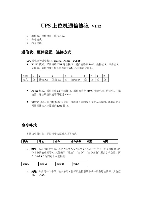
UPS上位机通信协议V1.121.通信软、硬件设置,连接方式。
2.命令格式3.指令详解通信软、硬件设置,连接方式UPS提供三种通信接口:RS232、RS485、TCP/IP。
●RS232模式,采用标准DB9通信接口。
通信波特率9600,数据位8,停止位1,无校验。
通信线缆长度不得超过13M。
各引脚定义如下:●RS485模式,采用标准5.0卡线接口。
通信波特率9600,数据位8,停止位1,无校验。
通信线缆长度不得超过300M。
●TCP/IP模式,采用标准RJ45接口,可通过直通网线直接接入局域网,或通过交叉网线直接接入计算机的RJ45接口。
命令格式本协议中所有上、下询指令均须遵从以下格式:1.帧头:共占用四个字节。
其中“长度A”、“长度B”各占一个字节,并互为校验(两个字节的值应相等),其值表示“地址”、“命令”、“命令参数”所占字节总数。
两个“0xEA”为固定十六进制数。
2.地址:共占用一个字节。
该字节用8位标识监控系统中唯一设备地址编号。
其值范围:1~200。
3.命令:共占用一个字节。
该字节包含两部分内容a)“数据传输方向”:下询帧时,数据传输方向位置“1”;上询指令时,数据方向位置“0”。
b)“指令代码”:以7位数值,标识系统唯一指令代码,指令代码表如下,详细内容参见“指令详解”。
4.命令参数:命令参数的所有字节均以十六进制数表示,其长度范围:0~253。
下询帧中,为指令代码辅助信息;上询帧中,为回复数据内容。
详细内容参见“指令详解”。
5.校验:共占用一个字节,其值为“地址”、“命令”、“命令参数”所有字节累加和的低八位。
6.帧尾:共占用一个字节,其值为固定十六进制数0x16。
指令详解1、查询系统数据1:0x01。
1)下询帧中命令参数部分长度为0 byte。
2)上询帧命令参数部分长度为51 byte,其内容、格式详见下表:a)特殊声明1:当电池电流值为正值时,表示电池充电电流,其数值的个位为实际电流的十分位;当电池电流为负值时,表示电池放电电流,其数值的个位为实际电流的个位。
UPS中文通讯协议

UPS中文通讯协议通信协议版本号: 3.0校对: Tony Lin准备:日期: Nov. 12, 1999文件:RICHPROT.DOC日期:V3.0 : August 30 ,2000通信协议内容A. 概述:本文档是专门阐述关于高智能型UPS的RS232C接口通信的。
协议中提供了以下内容:1、监视充电器状态;2、监视电池状态和环境;3、监视市电状态;4. 为计算机电源管理提供了定时开关电力供应的功能。
计算机能够通过一个以回车符结束的查询指令掌握信息的交流。
UPS则会返回以回车符结束的相应信息或者执行有关动作。
B. 硬件规范波特率............... :2400 bps数据长度.......... :8 bits停止位.....................:1 bit奇偶校验.................:无通信电缆引脚:计算机UPS===================================RX (pin 3) <---------- TX (pin 3)TX (pin 2) ----------> RX (pin 2)GND (pin 5) <---------- GND (pin 5)(9 针母头连接座)C、通信协议1、状态查询:计算机指令:Q1UPS返回值: UPS 状态数据流,例如(MMM.M NNN.N PPP.P QQQ RR.R S.SS TT.T b7b6b5b4b3b2b1b0UPS 状态数据流:为了区分各种不同参量的数据,在每段数值之间都有一个空格符。
以下是每段数值的具体含义:a. 启始字节:(b. 输入电压值:MMM.MM是0~9的整数。
单位是伏特。
c. I/P fault voltage : NNN.NN is and integer number ranging from 0 to 9.The unit is Volt.** For OFF LINE UPS**Its purpose is to identify a short duration voltage glitchwhich cause OFF line UPS to go to Invter mode. If this occurs input voltage will appear normal at query prior to glitch and will still appear normal at next query.The I/P fault voltage will hold glitch voltage till nextquery. After query, the I/P fault voltage will be same as I/Pvoltage until next glitch occurs.** For ON LINE UPS**Its purpose is to identify a short duration utility failwhich cause ON line UPS to go to battery mode. If this occurs input voltage will appear normal at query prior to fail andwill still appear normal at next query.The I/P fault voltage will hold utility fail voltage tillnext query. After query, the I/P voltage will be same as I/P voltage until next utility fail occurs.d. 输出电压值:PPP.PP是0~9的整数。
UPS2000-(6kVA-20kVA) Modbus协议开发指南 02
华为技术有限公司
地址: 网址:
பைடு நூலகம்
深圳市龙岗区坂田华为总部办公楼
邮编:518129
文档版本 02 (2016-03-10)
华为专有和保密信息
i
版权所有 © 华为技术有限公司
UPS2000-(6kVA-20kVA) Modbus 协议开发指南
前言
前言
概述
本文档主要介绍 UPS2000-(6kVA-20kVA)系列的通讯选配组件 RMS-MODBUS01A 卡与 上位机的通讯的 Modbus 协议、通讯建立流程示例。
读者对象
本指南主要适用于以下工程师: 技术支持工程师 维护工程师 产品用户
符号约定
在本文中可能出现下列标志,它们所代表的含义如下。
符号
说明
用于警示紧急的危险情形,若不避免,将会导致人员死亡 或严重的人身伤害。
用于警示潜在的危险情形,若不避免,可能会导致人员死 亡或严重的人身伤害。
用于警示潜在的危险情形,若不避免,可能会导致中度或 轻微的人身伤害。
1 通讯协议..........................................................................................................................................1
1.1 协议内容说明 ............................................................................................................................................................. 1
【精选】MGE系列UPS通讯协议 doc资料

MGE系列UPS通讯协议MERLIN GERINB Y M G E U P S S Y S T E M SDear Sir or Madam,Thank you for having chosen JBUS communication system and welcome to the ever growing family of satisfied MGE UPS SYSTEMS product users throughout the world.We hope that this manual will provide you with all the information you require to install and use your JBUS communication system.Please contact us for any other details you may require.MGE UPS SYSTEMStaking deliverycheckingThe option you have just acquired consists of the following items:c an installation and operating manual for the JBUS communication system;c an JBUS RS485 / RS232 connecting board;c two screws for fixing the JBUS communication board on the UPS.0Installation and operation of the JBUS communication system: E-51029066XT/AB MGE UPS SYSTEMSstorageIf you stored the device before using it,leave your communication board in its original packing in a dry place:c storage temperature: - 40°C to +70°C.packingYou should comply with applicable legal measures for the disposal of packing material.MGE UPS SYSTEMS JBUS : 51029066XT/ABMGE UPS SYSTEMS#define CPH 0 /* most significant bytes */#define CPL 1 /* least significant bytes *//* TABLE OF MOST SIGNIFICANT BYTES FOR CRC16 COMPUTATION*/char tbcrch [ ] ={0,193,129,64,1,192,128,65,1,192,128,65,0,193,129,64,1,192,128,65,0,193,129,64,0, 193,129,64,1,192,128,65,1,192,128,65,0,193,129,64,0,193,129,64,1,192,128,65,0,193,12 9,64,1,192,128,65,1,192,128,65,0,193,129,64,1,192,128,65,0,193,129,64,0,193,129,64,1, 192,128,65,0,193,129,64,1,192,128,65,1,192,128,65,0,193,129,64,0,193,129,64,1,192,12 8,65,1,192,128,65,0,193,129,64,1,192,128,65,0,193,129,64,0,193,129,64,1,192,128,65,1, 192,128,65,0,193,129,64,0,193,129,64,1,192,128,65,0,193,129,64,1,192,128,65,1,192,12 8,65,0,193,129,64,0,193,129,64,1,192,128,65,1,192,128,65,0,193,129,64,1,192,128,65,0, 193,129,64,0,193,129,64,1,192,128,65,0,193,129,64,1,192,128,65,1,192,128,65,0,193,12 9,64,1,192,128,65,0,193,129,64,0,193,129,64,1,192,128,65,1,192,128,65,0,193,129,64,0, 193,129,64,1,192,128,65,0,193,129,64,1,192,128,65,1,192,128,65,0,193,129,64,} ;/* TABLE OF LEAST SIGNIFICANT BYTES FOR CRC16 COMPUTATION*/char tbcrcl [ ] ={0,192,193,1,195,3,2,194,198,6,7,199,5,197,196,4,204,12,13,205,15,207,206,14,10,202,203,11,201,9,8,200,216,24,25,217,27,219,218, 26,30,222,223,31,221,29,28,220,20,212,213,21,215,23,22,214,210,18,19,211,17,209,208, 16,240,48,49,241,51,243,242,50,54,246,247,55,245,53,52,244,60,252,253,61,255,63,62,2 54,250,58,59,251,57,249,248,56,40,232,233,41,235,43,42,234,238,46,47,239,45,237,236, 44,228,36,37,229,39,231,230,38,34,226,227,35,225,33,32,224,160,96,97,161,99,163,162,98,102,166,167,103,165,101,100,164,108,172,173,109,175,111,110,174,170,106,107,171,105,169,168,104,120,184,185,1 21,187,123,122,186,190,126,127,191,125,189,188,124,180,116,117,181,119,183,182,118 ,114,178,179,115,177,113,112,176,80,144,145,81,147,83,82,146,150,86,87,151,85,149,1 48,84,156,92,93,157,95,159,158,94,90,154,155,91,153,89,88,152,136,72,73,137,75,139,1 38,74,78,142,143,79,141,77,76,140,68,132,133,69,135,71,70,134,130,66,67,131,65,129,1 28,64,} ;example of CRC16 computation in "C" using table lookup/******************************************************************* *******************************************************/ /*FUNCTION CALL: crc = crc16 (message, length ;*/ /*with char *message ; message = address of message*/ /**/ /*int length; length of received message (including CRC*/ /*expressed in number of bytes*/ /*int crc ; = CRC16 calculated from the"address", "code" and*//*"information" fields.*/ /**/ /*RETURN VALUE: crc 16 calculated (int crc*//*********************************************************************** ***************************************************/ int crc16 (message, lengthunsigned char message [ ] ;/* buffer containing message*//* for which the crc16 is to be calculated*/ int length;/* length of message to be checked*//* (including crc16*/ {/* beginning of the function*/ int i ;/* loop variable*/ int j ;/* calculation and displacement variable*/ union {/* calculated crc 16*/ int ival ;/* - whole*/ unsigned char cval [ 2 ] ;/* - table of 2 characters*//* unsigned is important since otherwise the sign*//* extension causes negative displacements with*//* respect to the beginning ot the table*/ } crcal/*$ initialization of calculated crc*/ crcal.ival = 0XFFFF ;i = 0 ;/*$ correction of the length ot be checked: remove the*//*$ received crc 16 from the length to be checked*/ length = length - 2 ;/*$ WHILE there are bytes to be checked DO*/ while ( i < length{/*$ calculate teh table indexj = (int ( message [ i ] ^ crcal.cval [ CPH ] ;/*$ most significant byte*/ crcal.cval [ CPH ] = tbcrch [ j ] ^ crcal.cval [ CPL ] ;/*$ least significatn byte*/ crcal.cval [ CPL ] = tbcrcl [ j ] ;/*$ next byte*/ i++ ;} ;/*$ END WHILE there are bytes to be checked*//*$ return the calculated crc*/ return ( crcal.ival ;}/* end of function*/ note: if the CRC is computed using table lookup, the most significant byte is transmitted first.remarks for the other UPS types:c normal operation for an "eco" UPS is equivalent to operation on mains 2 of an on-line UPS;c normal operation of a parallel-connected UPS is equivalent to normal operation of an on-line UPS;c operation on battery of an "eco" UPS is equivalent to operation on battery of an on-line UPS;c operation on battery of a parallel-connected UPS is equivalent to operation on battery of an on-line UPS;c operation on bypass of an "eco" UPS is equivalent to operation on bypass of an on-line UPS;c operation on bypass of a parallel-connected UPS is equivalent to operation on bypass of an on-line UPS.operation on standby mains 2 in on-line mode:normal system bit 400= 0 downgraded system (according to anomaly presencebit 403= 0 or 1 operation on battery: indifferent bit 404= X mains 1 input switch: indifferent (Q1bit 443= X rectifier/charger: indifferent bit 442= X battery circuit-breaker: indifferent (QF1bit 42F= X UPS not coupled bit 401= 0 UPS isolating switch closed (Q5Nbit 47B= 0 UPS bypass switch open (Q3BPbit 416= 0SS isolating switch closed (Q4Sbit 46E= 0 static switch (SS closed bit 407= 1 operation on "bypass" channel in on-line mode:normal system bit 400= 0 downgraded system (according to anomaly presencebit 403= 0 or 1 operation on battery: indifferent bit 404= X mains 1 input switch: indifferent (Q1bit 443= X rectifier/charger: indifferent bit 442= X battery circuit-breaker: indifferent(QF1bit 42F= X UPS coupled: indifferent bit 401= X UPS isolating switch open (Q5Nbit 47B= 1 UPS bypass switch closed (Q3BPbit 416= 1SS isolating switch open (Q4Sbit 46E= 1 static switch (SS open bit 407= 0description of the state state at 0state at 1word bit mains 1 frequency out of tolerance no yes44B major coupling fault no yes460 maintenance position no yes461 mains 2 overload no yes465 mains 2 thermal overload no yes466 mains 2 frequency out of tolerance no yes469 mains 2 voltage out of tolerance no yes46A phase M2 out of tolerance no yes46B mains 2 switch (Q4S state Q4S closed Q4S open46E K3N state K3N open K3N closed476 Q5N state Q5N closed Q5N open47B forced shutdown on external contact no yes47C number of UPS ready sufficient for coupling no yes47F charger general fault no yes490 battery charged state not charged charged493 major UPS fault no yes4C1 UPS overload no yes4C2 UPS thermal overload no yes4C3 UPS limitation no yes4C4 application thermal overload no yes4D F application overload no yes4F0table of measurements accessible by JBUS reads Units A, V, kW, kVA and Hz are given for a Galaxy PW type UPS.For lower power UPS systems, the units used are centiA, V, W, VA and Hz.Some of these measurements may not be activated on the UPS in question.In this case the measurement is maintained at a default value of 0.description of the physical quantity word unit I1 (I phase 1 mains 1100AI2 (I phase 2 mains 1101AI3 (I phase 3 mains 1102AI1 (I phase 1 UPS103AI2 (I phase 2 UPS104AI3 (I phase 3 UPS105AI1 (I phase 1 mains 2106AI2 (I phase 2 mains 2107AI3 (I phase 3 mains 2108AI1 (I phase 1 application109AI2 (I phase 2 application10A AI3 (I phase 3 application10B AI_Battery10E A device nominal active power111kW U12 mains 1115VU23 mains 1116VU31 mains 1117VU1N UPS118VU2N UPS119VU3N UPS11A VU12 UPS11B VU23 UPS11C VU31 UPS11D VU1N mains 211E VU2N mains 211F VU3N mains 2120VU12 mains 2121VU23 mains 2122VU31 mains 2123VU1N application124VU2N application125VU3N application126VU12 application127VU23 application128Vdescription of the physical quantity word unitU31 application129VU_battery12D V battery voltage end of backup threshold12E VP1 (application activated130kWP2 (application activated131kWP3 (application activated132kWS1 (application activated133kVAS2 (application activated134kVAS3 (application activated135kVAP application activated136kWS application apparent137kVA% application charge139(0-100 peak factor phase 113A(0-3 peak factor phase 213B(0-3 peak factor phase 313C(0-3 power factor x 10013D(0-100 mains 1 F13E Hz UPS F13F Hz mains 2 F140Hz application F141Hz nominal backup time148mn battery backup time149mn battery room temperature14A°C battery charging level14B%information description labelFor each item of information, the description is given (state if bit=0/state if bit = 1; bit address followed by the explanatory text.The information presented is available on a Galaxy PW type UPS.Information on the charger modulebattery circuit-breaker (QF1(O=open/1=closed; 42FBattery protection circuit-breaker "QF1" located next to the battery. This switch is closed in normal operation. It is either tripped or open. The application is then no longer protected as it ceases to benefit from battery backup if the mains 1 supply fails. UPS in backup mode(0=no/1=yes; 404The application is supplied by the UPS, but the mains 1 supply has failed or is out of limits and the UPS operates on battery.end of backup (in time or voltage(0=no/1=yes min.; 406The fault message indicates that the minimum battery voltage threshold is reached on operation on battery, and causes shutdown of the UPS that it supplies. battery running low alarm(0=no fault/1=alarm fault;405The fault message appears only when the UPS are running on battery and indicates that end of battery backup is approaching.rectifier/charger major fault(0=no fault/1=fault;490This message informs the user that therectifier/charger is defective and requiresintervention of the after-sales service.mains 1 input switch (Q1(0=closed/1=open;443"Q1" input switch of mains 1 supplying the rectifier/charger of a device. This switch is closed in normal operation. It is used to isolate the device from the mains 1 supply for maintenance purposes.Logic word 41.emergency stop contact(0=not controlled/1=controlled;40B Opening contact connected to devices. When activated, it causes shutdown of rectifiers/chargers and inverters and opening of static switches, as well as opening of "QF1" battery circuit-breakers.Provided that pressing the "Emergency stop" button has also caused opening of the protection devices delivering the voltages of mains 1 and the standby mains 2, theapplication is no longer supplied and the devices are de-energised.mains 1 input frequency out of tolerance (O=in tolerance/1=out of tolerance;44B The rectifier/charger stops when mains 1 input frequency is out of tolerance.battery compensation in progress (0=no compensation 1=compensation;425The rectifier/charger has deliberately been placed in compensation operation in order to standardise battery cell voltage.This operation stops all the UPS supplied by this battery (if these UPS have not been deliberately stopped beforehand.battery temperature out of tolerance(0=no fault/1=alarm fault;42AThis message informs the user that battery temperature is outside acceptable limits. The rectifier/charger has been placed in anoperating mode such that battery current is zero. The battery therefore no longer recharges (battery protection.mains 1 voltage out of tolerance(0=in tolerance/1=out of tolerance; 448This message indicates that mains 1 voltage is outside its tolerance range, thus causing charger shutdown.battery ventilation fault(0=no fault/1=fault;42DThis message informs the user that ventilation of the room containing the battery is defective. The rectifier/charger has been placed in an operating mode such that battery current is zero. The battery therefore no longer recharges (in order to avoid giving out hydrogen in the case of vented lead-acid batteries. We advise the user to take the necessary measures to repair the ventilationsystem.battery charging state(0=not charged/1=charged: 493This message informs the user that a batteryrecharging cycle is in progress (informationapplies for vented lead-acid batteries only.rectifier/charger on or off state(0=off/1=on: 442This message indicates operation orshutdown of a rectifier/charger. It stops oneach mains 1 power failure. The applicationis then supplied by the battery via the UPS.information on the UPS module major UPS fault (0=no fault/1=fault; 4C1 This message informs the user that the UPS is defective and requires the intervention of the after-sales service. UPS output current limitation (0=no limitation/1=limitation; 4C4 This message informs the user that an overload of more than 1.65 ln has occurred on the installation, causing UPS shutdown. UPS overload (0=no overload/1=overload; 4C2 This message indicates a UPS overload due to an application power factor of more than 0.9. UPS thermal overload (0=no overload/1=overload; 4C3 This message informs the user that the load is no longer supplied by the UPS due to prolonged overload. information on the coupling module device ventilation fault (0=no fault/1=fault; 40E This message informs the user of incorrect device ventilation caused by a fault in or shutdown of acooling fan. This fault does not cause UPS shutdown. status: UPS ready for coupling(0=not ready/1=ready; 414 This message informs the user that the UPS has the right voltage, frequency and phase to be connected in parallel. protected shutdown on external contact (0=no/1=yes; 40F This message informs the user that UPS shutdown will only occur when the transfer conditions of the load on mains 2 are fulfilled, in order not to cause voltage breaking on the load. This function is validated from Soft Tunor. forced shutdown on external contact (0=no/1=yes; 47C This message informs the user of UPS shutdown further to closing of the external contact on the customer terminal block. This function is validated from Soft Tunor. coupled UPS status (O=not coupled/1=coupled; 401 A UPS is in operation and is supplying the application. UPS shutdown disabled(0=enabled/1=disabled; 4CD The UPS shutdown control is not valid. major coupling fault (0=no fault/1=fault; 460 This message informs the user of an operating fault in the static changeover switch used to transfer the application between the UPS and the standby mains 2. The after-sales maintenance service must be called. mains 2 voltage out of tolerance (0=in tolerance/1=out of tolerance; 46A This message informs the user that mains 2 voltage is out of tolerance. Transfer, if any, of the application to mains 2 will take place with a voltage break of 0.8 second or not at all. mains 2 input switch (Q4S(0=closed/1=open; 46E "Q4S" switch placed in the phases of mains 2 at the input of the static switch in the standby channel, enabling devices to be isolated from mains 2. This switch is closed in normal operation. bypass switch (Q3BP (0=open/1=closed; 416"Q3BP"switch placed in bypass between the input of mains 2 and the application. This switch is open in normal operation. When it is closed (and "Q4S" and "Q5N" are open it ensures continuous power supply to the application via mains 2 when the device has been isolated for maintenance purposes. UPS output switch (Q5N (0=closed/1=open; 47B"Q5N" switch placed at the output of the UPS and used to isolate them from the application (or from the application busbars for parallel-connected devices. This switch is closed in normal operation. operation on static switch (0=no/1=yes; 407 The static switch on mains 2 is in the "open" position in normal operation (application supplied by the UPS.Transfer of the application to the static switch is controlled ("closed " position. when the UPS are no longer able to supply it (overload, end of battery backup time or internal anomaly. mains 2 frequency out of tolerance (0=in tolerance/1=out of tolerance; 469 When mains 2 frequency is out of tolerance, transfer, if any, of the application to mains 2 will take place with a voltage break of 0.8 second minimum or not at all. 33 MGE UPS SYSTEMS Installation and operation of the JBUS communication system: E-51029066XT/ABphase M2 out of tolerance (0=in tolerance/1=out of tolerance; 46B This message informs the user that the phase deviation between the UPS and mains 2 is out of limits. In these conditions any transfer of the application to mains 2 or to the UPS takes place with a voltage break. overload on mains 2 (0=no overload/1=overload; 465 The application supplied by mains 2 is in overload with respect to nominal current, but continues to be supplied by mains 2. mains 2 thermal overload (0=no overload/1=overload; 466 This message informs the user that the application is no longer supplied by mains 2 as a result of prolonged overload. overload (0=no overload/1=overload; 4F0 This message informs the user that there is an overload by a value of between In and 1.65 In. application thermal overload (0=no overload/1=overload; 4DF This message informs the user that the load is no longer supplied by the UPS due to prolonged overload. number of UPS ready sufficient for coupling (0=insufficient/1=sufficient; 47F This message only applies to parallelconnected type UPS with or without "static switch" cubicle. It informs the user that the number of UPS ready to be coupled to the application is not enough to supply the necessary power. Another UPS must be put into operation in order for the UPS group to be able to supply the application. Otherwise the application continues to be supplied by mains 2. process information summary end of battery backup time (0=no fault/1=end of backup time; 406 The backup time calculation indicates a time less than the threshold specified in battery meter customisation. end of battery life (0=no fault/1=end of life; 421 This message indicates that the battery has reached its maximum service life and must be replaced. protected load (0=not normal/1=normal; 400, information not significant for aUPS working in "eco" mode This state indicates normal operation of the device. NB: on parallel-connected UPS cubicles, this state only concerns the output of the device in question. The global installation application may, however, not be protected as it depends on other UPS. You must then consider all the "protected application" states of the various cubicles in the installation or the state of the "static switch" cubicle if any. system downgraded operation (0=not downgraded/1=downgraded; 403, information not significant for a UPS working in "eco" mode This state indicates an operating anomaly or environmental fault. However the application can still be supplied by the UPS. c operating anomalies: v ventilation fault of the standby static switch, v control fault of the standby static switch; c environmental faults: v battery temperature outside acceptable limits, v application overload of more than 5%, v mains 2 present but with voltage, frequency or phase with respect to the UPS outside acceptable limits. operation on battery (0=not on battery/1=battery; 404 This state indicates operation of the UPS on the battery, further to: c loss or voltage drop of the mains 1 power supply; c mains 1 insufficient power supply (e.g. generator set with energy top-up supplied by battery. operation on static switch (O=open/1=closed; 407 This state indicates operation on static switch of the mains 2 channel. The application is then supplied by mains 2. coupled UPS (O=not coupled/1=coupled; 401 This state indicates that the UPS is in operation and is supplying the application. UPS in on-line mode (0=no/1=yes; 411 This message informs the user that the application is supplied by the UPS in normal operation. UPS in "eco" mode(O=no/1=yes; 412 This message informs the user that the application is supplied by mains 2 in normal operation. unitary/parallel-connected UPS (0=unitary/1+parallel-connected; 413 This message informs the user that at least two UPS are connected in parallel. maintenance-position (0=not in maintenance/1=in maintenance; 461 This message informs the user that the application is supplied by mains 2 and that the UPS is isolated from the application. MGE UPS SYSTEMS 34 Installation and operation of the JBUS communication system: E-51029066XT/ABbattery test result (0= test in error/1=satisfactory test; 422 This message gives the state of the battery further to the last battery test run. battery manual test in progress (0=test sequence off/test sequence on; 424 This message informs the user that a battery test is being run further to an operator request. battery automatic test in progress (0=test sequence off/test sequence on; 428 This message informs the user that a battery test is being run further to a programmed request. (e.g.: 1 test a month. MGE UPS SYSTEMS Installation and operation of the JBUS communication system: E-51029066XT/AB 3536 Installation and operation of the JBUS communication system: E-51029066XT/AB MGE UPS SYSTEMS。
UPS通讯协议

UPS:C1-C2K协议1.UPS状态查询:Computer : Q1<cr>UPS: (MMM.M NNN.N PPP.P QQQ RR.R S.SS TT.T b7b6b5b4b3b2b1b0<cr>MMM.M 输入电压NNN.N 发生故障时的输入电压PPP.P 输出电压QQQ 负载RR.R 输入频率S.SS 电池电压TT.T 温度UPS状态信息: b7b6b5b4b3b2b1b02.故障信息查询:Computer: DF<cr>UPS: (KK PPP FF.F OOO EE.E LLL CCC PPP NNN BB.B TT.T <b7b6b5b4b3b2b1b0>KK ---故障类型,如下FF.F ----故障时频率值OOO---故障时输出电压值EE.E---故障时输出频率值LLL---故障时输出负载值CCC---故障时输出电流值PPP ----故障时正BUS电压NNN ----故障时负BUS电压BBB.B ---故障时电池电压值TT.T ---故障时机内温度值<b7b6b5b4b3b2b1b0> --状态标识UPSComputer: MD<cr>UPS: C1k, 700,V3.01,220,220,3,12.0,11.5,13.8<cr> UPS 几个参数控制:PEX使能下表的功能PDX禁止下表的功能常用:PEO 有旁路PDO(PF)取消旁路CF60 QF电池测试命令T 测试10秒TL 测试到电池低CT 取消测试. 修改RS232波特率命令:CB24 修改波特率为2400bpsCB48 修改波特率为4800bpsCB96 修改波特率为9600bps蜂鸣器的控制命令Q打开和关闭蜂鸣器。
UPS 厂商,型号,版本的修改在RS232.asm 文件最后部分修改即可。
找到如下表:I_1K_TAB:DB '#ZhuHai ATA UPS ataC1K V3.01 *' 上表含义如下,厂商名,型号,版本。
MR系列UPS上位机通信协议V111
MR系列UPS通信协议V1.111.通信软、硬件设置,连接方式。
2.命令格式3.指令详解通信软、硬件设置,连接方式MR系列UPS提供三种通信接口:RS232、RS485、TCP/IP。
●RS232模式,采用标准DB9通信接口。
通信波特率9600,数据位8,停止位1,无校验。
通信线缆长度不得超过13M。
各引脚定义如下:●RS485模式,采用标准5.0卡线接口。
通信波特率9600,数据位8,停止位1,无校验。
通信线缆长度不得超过300M。
●TCP/IP模式,采用标准RJ45接口,可通过直通网线直接接入局域网,或通过交叉网线直接接入计算机的RJ45接口。
命令格式本协议中所有上、下询指令均须遵从以下格式:1.帧头:共占用四个字节。
其中“长度A”、“长度B”各占一个字节,并互为校验(两个字节的值应相等),其值表示“地址”、“命令”、“命令参数”所占字节总数。
两个“0xEA”为固定十六进制数。
2.地址:共占用一个字节。
该字节用8位标识监控系统中唯一设备地址编号。
其值范围:1~200。
3.命令:共占用一个字节。
该字节包含两部分内容a)“数据传输方向”:下询帧时,数据传输方向位置“1”;上询指令时,数据方向位置“0”。
b)“指令代码”:以7位数值,标识系统唯一指令代码,指令代码表如下,详细内容参见“指令详解”。
4.命令参数:命令参数的所有字节均以十六进制数表示,其长度范围:0~253。
下询帧中,为指令代码辅助信息;上询帧中,为回复数据内容。
详细内容参见“指令详解”。
5.校验:共占用一个字节,其值为“地址”、“命令”、“命令参数”所有字节累加和的低八位。
6.帧尾:共占用一个字节,其值为固定十六进制数0x16。
指令详解1、查询系统数据1:0x01。
1)下询帧中命令参数部分长度为0 byte。
2)上询帧命令参数部分长度为51 byte,其内容、格式详见下表:a)特殊声明1:当电池电流值为正值时,表示电池充电电流,其数值的个位为实际电流的十分位;当电池电流为负值时,表示电池放电电流,其数值的个位为实际电流的个位。
PSMX-UPS独立监控协议(MODBUS_V01)

PSMX-UPS独立监控协议(Modbus )2011.1.04(V01)此文档是对本公司生产的通信电源电源,电力专用DC/DC电源智能设备接入用户集中监控网络提供的一种通信协议,RTU传输模式,符合Modbus规约.一、硬件规范1、通信接口:RS485接口2、数据格式:1位起始位,8位数据位,1位停止位,无校验3、波特率:2400 /4800/9600/19200bps4、设备地址:01-99(默认地址为01)5、接线端子:RS485+,RS485-二、帧格式1、RTU帧结构下行:设备地址功能代码起始地址数据长度CRC低字节CRC高字节1字节1字节2字节2字节1字节1字节上行:设备地址功能代码数据长度数据CRC低字节CRC高字节1字节1字节1字节N字节1字节1字节*下行指控制器向其他设备传送指令, 上行指设备向控制器回应数据。
通信电源主监控协议如下:1、RTU1.1遥测量命令格式:设备地址功能代码起始地址数据长度校验码01H 03H 0000H 000EH CRC16返回数据:设备地址功能代码数据长度数据校验码01H 03H 1CH 24Bytes CRC16数据定义:1.2遥测量(12Bytes)AddrHex Define Type Unit0000H UPS1输入电压Word 0.1V0001H UPS1输出电压Word 0.1V0002H UPS1旁路电压Word 0.1V0003H UPS1输出电流Word 0.1%0004H UPS1直流输入电压Word 0.1V0005H UPS1输入频率Word 0.1Hz0006H UPS1温度Word 0.1℃0007H UPS2输入电压Word 0.1V0008H UPS2输出电压Word 0.1V0009H UPS2旁路电压Word 0.1V000AH UPS2输出电流Word 0.1%000BH UPS1直流输入电压Word 0.1V000CH UPS2输入频率Word 0.1Hz000DH UPS2温度Word 0.1℃2.1遥信量命令格式:设备地址功能代码起始地址数据长度校验码01H 04H 0100H 0002H CRC16返回数据:设备地址功能代码数据长度数据校验码01H 04H 04H 2Byte CRC16数据定义:2.2遥信量:(1Byte) (高位先发)位序RTU0100H 描述7 1 : UPS1交流输入异常6 1 : UPS1直流输入异常5 1 : UPS1旁路输出4 1 : UPS1故障3 1 : UPS1过载2 1 : UPS1旁路异常10101H7 1 : UPS2交流输入异常6 1 : UPS2直流输入异常5 1 : UPS2旁路输出4 1 : UPS2故障3 1 : UPS2过载2 1 : UPS2旁路异常10102H7 1 : 开关监控通讯故障6 1 : 状态监控通讯故障5 1 : UPS通讯故障43210103H765 1:交流输出断路器跳闸4 : 1:旁路输入断路器跳闸3 1:交流输入断路器跳闸2 : 1:直流输入断路器跳闸1 1:交流(直流)输入防雷器故障0 : 1:馈线开关跳闸故障(并线)3.3遥信量命令格式:设备地址功能代码起始地址数据长度校验码01H 04H 0200H 0008H CRC16返回数据:设备地址功能代码数据长度数据校验码01H 04H 10H 8Byte CRC16数据定义:(8Bytes)字节位内容报警字节位内容报警0200 BIT0 馈线开关01状态N0201BIT0 馈线开关09状态N BIT1 馈线开关02状态N BIT1 馈线开关10状态NBIT3 馈线开关04状态N BIT3 馈线开关12状态N BIT4 馈线开关05状态N BIT4 馈线开关13状态N BIT5 馈线开关06状态N BIT5 馈线开关14状态N BIT6 馈线开关07状态N BIT6 馈线开关15状态N BIT7 馈线开关08状态N BIT7 馈线开关16状态N0202 BIT0 馈线开关17状态N0203BIT0 馈线开关25状态N BIT1 馈线开关18状态N BIT1 馈线开关26状态N BIT2 馈线开关19状态N BIT2 馈线开关27状态N BIT3 馈线开关20状态N BIT3 馈线开关28状态N BIT4 馈线开关21状态N BIT4 馈线开关29状态N BIT5 馈线开关22状态N BIT5 馈线开关30状态N BIT6 馈线开关23状态N BIT6 N BIT7 馈线开关24状态N BIT7 N0204 BIT0 馈线开关31状态N0205BIT0 馈线开关39状态N BIT1 馈线开关32状态N BIT1 馈线开关40状态N BIT2 馈线开关33状态N BIT2 馈线开关41状态N BIT3 馈线开关34状态N BIT3 馈线开关42状态N BIT4 馈线开关35状态N BIT4 馈线开关43状态N BIT5 馈线开关36状态N BIT5 馈线开关44状态N BIT6 馈线开关37状态N BIT6 馈线开关45状态N BIT7 馈线开关38状态N BIT7 馈线开关46状态N0206 BIT0 馈线开关47状态N0207BIT0 馈线开关55状态N BIT1 馈线开关48状态N BIT1 馈线开关56状态N BIT2 馈线开关49状态N BIT2 馈线开关57状态NBIT4 馈线开关51状态N BIT4 馈线开关59状态BIT5 馈线开关52状态N BIT5 馈线开关60状态BIT6 馈线开关53状态N BIT6BIT7 馈线开关54状态N BIT7。
UPS(PTU)通讯说明中文

通讯协议转换器(PTU)说明0.01(本说明只适用于三单(电力专用)机型)DB9针定义(标准DTE接口)绿端子定义电源交流220V,50Hz电源LED正面LED1 ---●●●●●●--- LED6板接口图拨码开关位用途位状态1板地址设置0 1 0 1……0 12 0 0 1 1 1 13 0 0 0 0 1 14 0 0 0 0 1 1板地址无效1(默认) 2 3 ……14 15 拨码开关位用途位状态5 UPS波特率设置0 1 0 16 0 0 1 17 上位机波特率设置0 1 0 18 0 0 1 1波特率2400 4800 9600 无效UPS波特率默认为9600,上位机波特率默认为2400与上位机通讯协议(遵循MODBUS协议)波特率:2400(默认)/4800/9600起始位:1位奇偶校验位:无结束位:1位上位机命令:地址码(1B)+功能码(1B)+寄存器起始地址(2B)+寄存器数量(2B)+CRC校验码(2B)PTU应答:地址码(1B)+功能码(1B)+数据字节数(1B)+数据1(2B)+…+数据n(2B)+CRC校验码(2B)注1:上面2B的信息中,高字节在前注2:功能码为03表中红色部分为本机型有效数据,黑色部分为本机型无效数据,程序中将无效数据添零。
ModBus/RTU 地址表一(参数寄存器)(3入1出/电力专用)说明一BIT0 Alarm Temperature 温度报警0 = No Alarm Active, 1 = Alarm Active BIT1 Alarm Input Bad 主输入消失报警0 = No Alarm Active, 1 = Alarm Active BIT2 Alarm Output Bad 输出消失报警0 = No Alarm Active, 1 = Alarm Active BIT3 Alarm Overload 过载报警0 = No Alarm Active, 1 = Alarm Active BIT4 Alarm Bypass Bad 旁路消失报警0 = No Alarm Active, 1 = Alarm ActiveBIT5 Alarm Output Off 输出关闭报警0 = No Alarm Active, 1 = Alarm Active BIT6 Alarm UPS Shutdown UPS紧急停机报警0 = No Alarm Active, 1 = Alarm Active BIT7 Alarm Charger Failure 充电器故障报警0 = No Alarm Active, 1 = Alarm Active BIT8 Alarm System Off系统关闭报警0 = No Alarm Active, 1 = Alarm Active BIT9 Alarm Fan Failure 风扇故障报警0 = No Alarm Active, 1 = Alarm Active BIT10 Alarm Fuse Failure 保险故障报警0 = No Alarm Active, 1 = Alarm Active BIT11 Alarm General Fault 综合故障报警0 = No Alarm Active, 1 = Alarm ActiveBIT12 Alarm Awaiting Power 等待电源0 = No Alarm Active, 1 = Alarm ActiveBIT13 Alarm Shutdown Pending 准备关机报警0 = No Alarm Active, 1 = Alarm ActiveBIT14 Alarm Shutdown Imminent即将关机报警0 = No Alarm Active, 1 = Alarm Active。
ups控制器通讯规约

UPS与综合自动化系统的通讯协议1.前言UJK2003A UPS监控器通讯规约是深圳奥特迅公司UPS监控系统与外部网络或综合自动化系统(以下简称RTU)之间通讯接口所使用的规约。
2. 通信格式半双工异步串行通讯,波特率:可选(1.2—9.6Kbps),数据格式为每帧10位,1位起始位、8位数据位、1位停止位, 无奇偶校验位。
3. 数据传输报文格式JKQ011 <==> RTU:1234说明:“长度” = 数据区字节数+5, 为16进制数, “长度”不大于FEH, 即254个字节;“目标地址”指报文接收方地址;“源地址”指报文发送方地址;“命令码”用于说明报文种类,具体含义见下文;“数据区”指“命令码”与“校验和”之间的字节;“校验和”为“长度”、“目标地址”、“源地址”、“命令码”、“数据区”各字节算术和的低16位,低8位在前,高8位在后。
4. 采集UPS系统模拟量(遥测)RTU ——〉UJK2003005H长度11FH目标地址210H源地址380H命令码4CHKL 5CHKH校验和0 长度1 目标地址2 源地址3 命令码45 校验和JKQ011071数据长度 = 116 110H目标地址21FH源地址330H4Year年5Mon0 数据长度 = 1161 目标地址2 源地址34 年5 月6 日7 时8 分9 秒1011 #1交流输入电压121314 1#交流输入电流151617 1#旁路输入电压181920 1#旁路输入电流212223 1#直流输入电压242526 1#直流输入电流272829 1#逆变输出电压303132 1#逆变输出电流333435 1#UPS温度363738 #2交流输入电压394041 2#交流输入电流424344 2#旁路输入电压454647 2#旁路输入电流484950 2#直流输入电压515253 2#直流输入电流545556 2#逆变输出电压575859 2#逆变输出电流606162 2#UPS温度636465 交流输出电压666768 交流输出电流697071说明:说明:每个数值用三个字节表示。
科华UPS模块化UPS通信协议V1.2

BCD 码小数位
剩余放电时间 电池电压+ 电池电压-
BCD 码千位
BCD 码百位
min
BCD 码十位
BCD 码个位
BCD 码百位 BCD 码个位
BCD 码十位 BCD 码小数位
V
BCD 码百位 BCD 码个位
BCD 码十位 BCD 码小数位
V
系统状态字节 1
1 D0 旁路状态 D1 旁路输入过欠压 D2 旁路输入频率异常 D3 旁路输入相序错 D4 旁路输入缺相 D5 逆变输出过欠压 D6 逆变输出频率异常 D7 逆变输出缺相
(0x8a~0x8d)。
遥信指令: 命令码 0x81 0x82 0x83 0x84
命令含义 查询系统交、直流电压电流 查询各模块数据 查询电池额定容量、放电时间、单体电压等 查询系统信息(系统型号、协议版本、软件版本)
参数 00 模块编号 00 00
表 1-2
控制命令: 命令码 0x8A 0x8B 0x8C 0x8D
通信协议
命令含义 开、关机命令 旁路逆变切换 放电与停止放电 系统对时
参数 0 开机 1 关机 0 转逆变 1 转旁路 0 停止放电 1 放电 年(BCD 码) 月(BCD 码) 日(BCD 码) 时(BCD 码) 分(BCD 码) 秒(BCD 码)
表 1-3
6、 校验和 : 地址码、命令码、命令参数所有字节相加后低 8 位。
通信协议
查询命令(0x01):
系统电压、电流、功率及相关状态量:
市电电压 A 相
BCD 码百位 BCD 码个位
BCD 码十位 BCD 码小数位
V
市电电压 B 相
BCD 码百位 BCD 码个位
BCD 码十位 BCD 码小数位
- 1、下载文档前请自行甄别文档内容的完整性,平台不提供额外的编辑、内容补充、找答案等附加服务。
- 2、"仅部分预览"的文档,不可在线预览部分如存在完整性等问题,可反馈申请退款(可完整预览的文档不适用该条件!)。
- 3、如文档侵犯您的权益,请联系客服反馈,我们会尽快为您处理(人工客服工作时间:9:00-18:30)。
MR系列UPS通信协议V1.11
1.通信软、硬件设置,连接方式。
2.命令格式
3.指令详解
通信软、硬件设置,连接方式
MR系列UPS提供三种通信接口:RS232、RS485、TCP/IP。
●RS232模式,采用标准DB9通信接口。
通信波特率9600,数据位8,停止位1,
无校验。
通信线缆长度不得超过13M。
各引脚定义如下:
●RS485模式,采用标准5.0卡线接口。
通信波特率9600,数据位8,停止位1,无
校验。
通信线缆长度不得超过300M。
●TCP/IP模式,采用标准RJ45接口,可通过直通网线直接接入局域网,或通过交叉
网线直接接入计算机的RJ45接口。
命令格式
本协议中所有上、下询指令均须遵从以下格式:
1.帧头:共占用四个字节。
其中“长度A”、“长度B”各占一个字节,并互为校验(两
个字节的值应相等),其值表示“地址”、“命令”、“命令参数”所占字节总数。
两
个“0xEA”为固定十六进制数。
2.地址:共占用一个字节。
该字节用8位标识监控系统中唯一设备地址编号。
其值范
围:1~200。
3.命令:共占用一个字节。
该字节包含两部分内容
a)“数据传输方向”:下询帧时,数据传输方向位置“1”;上询指令时,数据方
向位置“0”。
b)“指令代码”:以7位数值,标识系统唯一指令代码,指令代码表如下,详细
内容参见“指令详解”。
4.命令参数:命令参数的所有字节均以十六进制数表示,其长度范围:0~253。
下询
帧中,为指令代码辅助信息;上询帧中,为回复数据内容。
详细内容参见“指令详
解”。
5.校验:共占用一个字节,其值为“地址”、“命令”、“命令参数”所有字节累加和的
低八位。
6.帧尾:共占用一个字节,其值为固定十六进制数0x16。
指令详解
1、查询系统数据1:0x01。
1)下询帧中命令参数部分长度为0 byte。
2)上询帧命令参数部分长度为51 byte,其内容、格式详见下表:
a)特殊声明1:当电池电流值为正值时,表示电池充电电流,其数值的个位为实际电
流的十分位;当电池电流为负值时,表示电池放电电流,其数值的个位为实际电流的个位。
2、查询单个模块数据:0x02。
1)下询帧中命令参数部分长度为1 byte,命令参数用一个字节提交待查询模块的地址
号。
地址号范围:1~15。
2)上询帧中命令参数部分长度为49 byte,其内容、含义详见下表:
3、查询告警数据:0x03。
1)下询帧中命令参数部分长度为0 byte。
2)上询帧中命令参数部分包含两部分信息:记录数量和记录N。
每个记录须占用8
个字节,以表示报警发生的时间和事件信息。
记录数量为记录的数量,其范围为:0~5。
命令参数部分的内容、格式详见下表:
b)模块报警序号
c)当“报警序号”等于15或18时,表示模块报警信息,且只有此时“模块报警
序号”才有意义。
“模块报警序号”的低四位表示该警报发生的模块ID号。
4、查询电池管理参数:0x04。
a)下询帧中命令参数部分长度为0 byte。
5、查询系统数据2:0x06。
3)下询帧中命令参数部分长度为0 byte。
4)上询帧命令参数部分长度为22byte,其内容、格式详见下表:
6、UPS开、关机遥控操作:0x0A。
当“开关机操作标识符”置“1”时,为遥控UPS开机指令;当“开关机操作标识符”置“0”时,为遥控UPS关机指令。
当“操作接受标识符”置“1”时,表示下发操作指令被设备接收并执行;当“操作接受标识符”置“0”时,表示下发操作指令被设备接收到,但拒绝执行。
7、电池充电遥控操作:0x0B。
当“均浮充操作标识符”置“1”时,为遥控UPS对电池均充指令;当“均浮充操作标识符”置“0”时,为遥控UPS对电池浮充指令。
b)上询帧中命令参数部分长度为1 byte。
表示操作申请是否被设备接受。
当“操作接受标识符”置“1”时,表示下发操作指令被设备接收并执行;当“操作接受标识符”置“0”时,表示下发操作指令被设备接收到,但拒绝执行。
8、UPS与监控机对时操作:0x0C。
当“操作接受标识符”置“1”时,表示下发操作指令被设备接收并执行;当“操作接受标识符”置“0”时,表示下发操作指令被设备接收到,但拒绝执行。
9、电池管理参数设置操作:0x0D。
当“操作接受标识符”置“1”时,表示下发操作指令被设备接收并执行;当“操作接受标识符”置“0”时,表示下发操作指令被设备接收到,但拒绝执行。
附录
⏹HEX-1格式:由两个字节组成,以十六位表示一无符号整形数据量:
⏹HEX-2格式:由两个字节组成,以十六位表示一有符号整形数据量。
数据高八位的D7
位为正负标志位,“1”表示负数;“0”表示整数:
⏹HEX-3格式:由一个字节组成,以八位表示一无符号字符型数据量。
⏹HEX-4格式:由一个字节组成,八位分别表示八种状态。
当该状态置“1”时,表示处
于文字描述状态;当该状态置“0”时,表示处于文字描述相反的状态。
