Worst-case Timing Analysis of Exception Handling
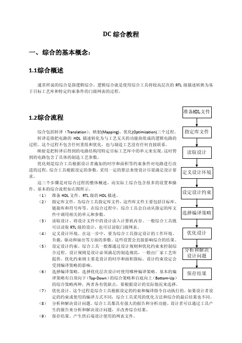
DC教程
该变量给出了 DC 环境下读入的文件(包括库文件和设计文件)的搜寻路径。当读入没有给出路 径的文件时,DC 则按照 search_path 给出的路径搜索该文件。
如果 search_path 表示多个路径,用 list 将所有路径组合成一个集合。
目标工艺库(target_library)
三、目录组织结构
做综合时各文件的存放目录没有严格的规定,但为了便于管理和查看,一般会分类放在不同的 目录下,下面是一个目录组织结构的范例:
四、操作步骤
Step1:启动 DC 首先进入 deller 服务器,打开一个 Terminal,输入命令:
source cshrc_eda
然后按照前面讲的目录结构建立文件夹,把所需要的文件放入相应的文件夹,进入工作目录 run, 这时在 terminal 中输入命令: design_vision&
6.2 pbist.read
该文件为读取原始的设计文件,内容如下
analyze 语句读入设计文件,‐format 选项的值为 verilog(源代码用 verilog 编写)或 vhdl(源代 码用 vhdl 编写),elaborate 语句建立一个 design,design 的名字为设计文件中 module 的名字。一般 最后读入顶层模块所在的文件,这样执行完所有的语句后,current_design 就是顶层模块对应的 design,这也是后面综合的对象。
进的过程。综合工具根据设定的参数,采用一定的算法来使设计尽量满足设计要 定义设计环境
求。
这三个步骤是对综合过程的整体概述,而实际上综合包含很多的设置和操
作。基本的综合流程如右图所示。 (1) 准备 HDL 文件。RTL 级的 HDL 描述。
PSPICE仿真讲解学习

P S P I C E仿真目录介绍: (3)新建PSpice仿真 (4)新建项目 (4)放置元器件并连接 (4)生成网表 (6)指定分析和仿真类型 (7)Simulation Profile设置: (8)开始仿真 (8)参量扫描 (11)Pspice模型相关 (13)PSpice模型选择 (13)查看PSpice模型 (13)PSpice模型的建立 (14)介绍:PSpice是一种强大的通用模拟混合模式电路仿真器,可以用于验证电路设计并且预知电路行为,这对于集成电路特别重要。
PSpice可以进行各种类型的电路分析。
最重要的有:●非线性直流分析:计算直流传递曲线。
●非线性瞬态和傅里叶分析:在打信号时计算作为时间函数的电压和电流;傅里叶分析给出频谱。
●线性交流分析:计算作为频率函数的输出,并产生波特图。
●噪声分析●参量分析●蒙特卡洛分析PSpice有标准元件的模拟和数字电路库(例如:NAND,NOR,触发器,多选器,FPGA,PLDs和许多数字元件)分析都可以在不同温度下进行。
默认温度为300K电路可以包含下面的元件:●Independent and dependent voltage and current sources 独立和非独立的电压、电流源●Resistors 电阻●Capacitors 电容●Inductors 电感●Mutual inductors 互感器●Transmission lines 传输线●Operational amplifiers 运算放大器●Switches 开关●Diodes 二极管●Bipolar transistors 双极型晶体管●MOS transistors 金属氧化物场效应晶体管●JFET 结型场效应晶体管●MESFET 金属半导体场效应晶体管●Digital gates 数字门●其他元件 (见用户手册)。
新建PSpice仿真新建项目如图 1所示,打开OrCAD Capture CIS Lite Edition,创建新项目:File > New > project。
03-PSPICE仿真 (1)
23
模型参数
24
加元器件库(Place/Part命令)
在画电路图之前,首先要为将要画的电路选择元器件库。执行 Place/Part命令,,在Place/Part对话框中点击“Add”按钮,出现 Browse File对话框,将所需库点中,点击“打开”按钮,则选中的 库文件增至“Labrarise”框 中。反之,从“Labrarise”框,选中一 个库文件,点击Remove按钮,即将该库文件框剔除。
1/TSTOP
VAMPL
FREP TD DF PHASE
振幅
频率 延迟时间 阻尼系数 相位延迟
V
Hz s 1/s 度
FREQ=1kHz,TD=0,DF=0,
PHASE=0。可得如图所示的 正弦波形。
33
PSpice A/D中的有关规定
比例因子
PSpice A/D中不区分大小写 要特别注意M与MEG的差别 M——10-3 MEG —— 106
6
(2)OrCAD/PSpice9软件覆盖了 电子设计的4项核心任务
OrCAD/Capture CIS (电路原理图设计软件)
电路仿真
OrCAD/PSpice A/D (数/模混合模拟软件) Optimizer (电路优化设计)
OrCAD/Express Plus (CPLD/FGPA设计软件)
OrCAD/Layout Plus (PCB设计软件)
例如要表示100兆赫兹的频率时,必须写成100MEG,而不能 是100M。否则PSpice A/D将其理解为100毫赫兹。
34
PSpice A/D中的有关规定
单位
PSpice A/D仿真运行的结果都是以A、V、、Hz、W(瓦) 等标准单位的形式确定,且省略了单位。
OrCAD-pspice使用说明
图6
结束放置可用快捷方式,即点击鼠标由键,出现图 7 所 示菜单。执行“End Mode”即结束放置。若元件需要旋转, 则选中要旋转的元件,执行图 7 中的“Rotate”命令,元件旋 转 90°,依次执行该命令可继续旋转。也可从 Capture 主菜单 中执行 Edit\Rotate。
(2) 放置 VCVS 和 CCVS:可从图 6 元件列表中分别选元 件 E 和 H。放置操作与放置电阻元件相同。
计算机辅助设计(Computer-Aided Design-CAD) 电子设计自动化(Electronic Design Automation-EDA) CAD 技术是一种通用技术,在各行各业均得到了广泛的应用。尤其是在电子行业中, 其应用不仅面广,而且发展迅速。在设计自动化(DA:Design Automation)方面更是取得 了突破性的进展。目前,在电子设计领域,设计技术正从 CAD 向 DA 过渡,一般统称为电 子设计自动化(EDA)。 OrCAD 公司是开发 EDA 技术的突出代表。OrCAD 开发的软件是一个完整的 EDA 系统, 其主要构成如图 1 所示。
下面以图直流电阻电路为例说明绘制方法:
4U2
2Ω
+I
+
3Ω 10V
12Ω U2
−
−
12Ω
+ 6I −
图5 (1) 放置电阻:由图 4 中选择执行 Place\Part,从 Labraries 中选中 ANALOG,再从显示 的元件列表中选择电阻元件 R,然后按 OK 按钮即可在 Schematic1 窗口中放置元件 R 了(见 图 6)。点击鼠标左键,一个电阻元件便放置完成,重复按鼠标左键可继续放置第 2 个,第 3 个,…,电阻元件。
OrCAD操作指南
三.
Prob模块显示窗模拟示波器的显示效果,同时可对图形进行适当的分析。
在显示窗上增加图形。点击后出现下面对话框:
左边栏目选择要显示波形的节点处。右边栏目可选择计算公式。下边栏目列表达式。点击OK按键后,对应节点表达式的波形将显示在屏幕上。用这种办法可得到更多的显示信息。比如可用输入电压比输入电流得到输入阻抗。
噪声分析是计算电路各部分在各点频上的噪声等效为输入噪声源位置上的输入噪声。以此计算出等效输出噪声,结果以文件的形式输出。可在输出文件中查到。
Bias Point:
在分析偏置时,Pspice将电路中的电容开路电感短路,对各信号源取其直流电平值,用迭代法计算电路的直流偏置状态。
在Analysis type栏中选中bias Point,Options栏中选中Save Bias Point,Output file options栏选中Include detailed bias point information for nonlnear controlled sources and semiconductor,就可以进行偏置(直流工作点)分析了。Perform Sensitivity analysis用于直流灵敏度分析,Calculate small-signal DC gain用于计算直流传输特性分析。
傅立叶变换,进行时域分析后选此按键可进行傅立叶变换,结果以频谱显示在屏幕上。
文本标签,在屏幕上设置文本标签。
测试点坐标,测试任意点的坐标。
标注座标值。
*点击菜单栏的window/copy to clipboard可将屏幕显示的图形放入剪贴版,粘贴到word文档中。
orcad 电路仿真
OrCAD/PSpice9的电路仿真方法1、概 述1.1 PSpice 软件P S p i c e是一个电路通用分析程序,是E D A中的重要组成部分,它的主要任务是对电路进行模拟和仿真。
该软件的前身是S P I C E(S i m u l a t i o n P r o g r a m w i t h I n t e g r a t e d C i r c u i t E m p h a s i s),由美国加州大学伯克莱分校于1972年研制。
1975年推出正式实用化版本S P I C E2G,1988年被定为美国国家标准。
1984年M i c r o s i m公司推出了基于S P I C E的微机版本P S p i c e (P e r s o n a l-S P I C E),此后各种版本的S P I C E不断问世,功能也越来越强。
进入20世纪90年代,随着计算机软件的飞速发展,特别是W i n d o w s操作系统的广泛流行,P S p i c e又出现了可在W i n d o w s环境下运行的5.1、6.1、6.2、8.0等版本,也称为窗口版,采用图形输入方式,操作界面更加直观,分析功能更强,元器件参数库及宏模型库也更加丰富。
1998年1月,著名的E D A公司O r C A D公司与开发P S p i c e软件的M i c r o s i m公司实现了强强联合,于1998年11月推出了最新版本O r C A D/P S p i c e9。
为了迅速推广普及O r C A D/P S p i c e9软件,O r C A D公司提供了一张试用光盘O r C A D/P S p i c e 9D e m o, 它与商业版是完全一致的,不同之处只是在元器件上受到一定的限制,因此又被称为普及版。
本章将以普及版为例简要介绍O r C A D/P S p i c e9的功能及使用方法。
本书中所有的虚拟实验都是用O r C A D/P S p i c e9D e m o完成的,所引用的屏幕画面也都是出自于O r C A D/P S p i c e 9D e m o软件。
case analysis范文
case analysis范文Case Analysis: An In-depth Examination of a Specific CaseIntroduction:Case analysis is a method used to study and understand a specific case thoroughly. It involves a detailed examination of the case, identification of key issues, analysis of possible solutions, and recommendations for future actions. In this article, we will discuss the importance of case analysis and its relevance in various fields.Body:1. Importance of Case Analysis:Case analysis is essential for several reasons. Firstly, it allows researchers to gain a deep understanding of the case under study. By analyzing the details, context, and intricacies of a case, researchers can identify patterns, causes, and effects. This comprehensive understanding helps in making informed decisions and formulating effective strategies.2. Process of Case Analysis:The process of case analysis typically involves several steps. These include:a) Identifying the Problem: The first step is to identify the problem or issue that needs to be addressed. This requires a clear understanding of the case and its context.b) Gathering Relevant Information: Once the problem is identified, the next step is to gather all the relevant information related to the case. This may include data, documents, interviews, or other sources.c) Analyzing the Information: After gathering the information, it is important to analyze it critically. This involves identifying patterns, trends, and relationships among the data points.d) Developing Solutions: Based on the analysis, potential solutions or strategies can be developed. These solutions should address the root causes of the problem and be feasible to implement.e) Evaluating Alternatives: It is important to evaluate the potential solutions and compare them based on their feasibility, effectiveness, and potential impact. This helps in selecting the most suitable solution.f) Making Recommendations: Finally, based on the evaluation,recommendations can be made for future actions. These recommendations should be practical, actionable, and aligned with the goals of the case.3. Applications of Case Analysis:Case analysis is widely used in various fields, including business, law, medicine, and social sciences. Some specific applications include:a) Business Strategy: Case analysis is often used in the business world to analyze market trends, competitive landscapes, and customer behavior. It helps in formulating effective strategies and making informed business decisions.b) Legal Cases: In the field of law, case analysis is crucial for understanding legal precedents, interpreting legislation, and building strong arguments. It allows lawyers to analyze past cases and apply relevant legal principles to their case.c) Medical Research: Case analysis plays a significant role in medical research. It helps in understanding diseases, identifying risk factors, and developing treatment protocols. Case analysis also helps in identifying potential adverse events and improving patient outcomes.d) Social Sciences: In social sciences, case analysis is used to study human behavior, societal issues, and cultural phenomena. Researchers analyze individual cases to draw broader conclusions and understand social patterns.Conclusion:Case analysis is a valuable method for gaining a deep understanding of a specific case. By following a systematic process, researchers can identify key issues, analyze information, and develop effective solutions. This method finds applications in various fields and contributes to informed decision-making and problem-solving. Mastering the art of case analysis can be beneficial for professionals in diverse industries.。
FPGA可编程逻辑器件芯片EP3C40F484C8N中文规格书
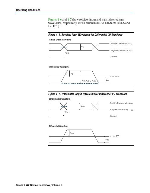
Figures4–6 and 4–7 show receiver input and transmitter output waveforms, respectively, for all differential I/O standards (LVDS and LVPECL).Figure4–6.Receiver Input Waveforms for Differential I/O StandardsFigure4–7.Transmitter Output Waveforms for Differential I/O StandardsPin CapacitanceTable 4–51 shows the Stratix II GX device family pin capacitance.Table 4–50.Series and Differential On-Chip Termination Specification for Left I/O Banks Note (1)SymbolDescription Conditions Resistance ToleranceCommercial Max Industrial Max Unit 25-Ω R S3.3/2.5Internal series termination without calibration (25-Ω setting )V CCIO = 3.3/2.5V ±30 ±30%50-Ω R S3.3/2.5/1.8Internal series termination without calibration (50-Ω setting )V CCIO = 3.3/2.5/1.8V ±30 ±30%50-Ω R S 1.5Internal series termination without calibration (50-Ω setting )V CCIO = 1.5V ±36 ±36%R D Internal differential termination forLVDS (100-Ω setting)V CCIO = 2.5 V ±20 ±25%Note to Table 4–50:(1)On-chip parallel termination with calibration is only supported for input pins.Table 4–51.Stratix II GX Device CapacitanceNote (1)SymbolParameter Typical Unit C IOTBInput capacitance on I/O pins in I/O banks 3, 4, 7, and 8. 5.0pF C IOLInput capacitance on I/O pins in I/O banks 1 and 2, including high-speed differential receiver and transmitter pins. 6.1pF C CLKTBInput capacitance on top/bottom clock input pins: CLK[4..7] and CLK[12..15]. 6.0pF C CLKLInput capacitance on left clock inputs: CLK0 and CLK2. 6.1pF C CLKL+Input capacitance on left clock inputs: CLK1 and CLK3. 3.3pF C OUTFB Input capacitance on dual-purpose clock output/feedback pins in PLLbanks 11 and 12. 6.7pFNote to Table 4–51:(1)Capacitance is sample-tested only. Capacitance is measured using time-domain reflections (TDR). Measurementaccuracy is within ±0.5pF.DC and Switching CharacteristicsPower Consumption Altera offers two ways to calculate power for a design: the Excel-based PowerPlay early power estimator power calculator and the Quartus® II PowerPlay power analyzer feature.The interactive Excel-based PowerPlay early power estimator is typically used prior to designing the FPGA in order to get an estimate of device power. The Quartus II PowerPlay power analyzer provides better quality estimates based on the specifics of the design after place-and-route is complete. The power analyzer can apply a combination of user-entered, simulation-derived and estimated signal activities which, combined with detailed circuit models, can yield very accurate power estimates.In both cases, these calculations should only be used as an estimation of power, not as a specification.f For more information on PowerPlay tools, refer to the PowerPlay EarlyPower Estimators (EPE) and Power Analyzer, the Quartus II PowerPlayAnalysis and Optimization Technology, and the PowerPlay Power Analyzerchapter in volume 3 of the Quartus II Handbook. The PowerPlay earlypower estimators are available on the Altera web site atwww.altera. com.1See Table4–23 on page42 for typical I CC standby specifications. Timing Model The DirectDrive technology and MultiTrack interconnect ensurepredictable performance, accurate simulation, and accurate timinganalysis across all Stratix II GX device densities and speed grades. Thissection describes and specifies the performance, internal, external, andPLL timing specifications.All specifications are representative of worst-case supply voltage andjunction temperature conditions.Preliminary and Final TimingTiming models can have either preliminary or final status. The Quartus IIsoftware issues an informational message during the design compilationif the timing models are preliminary. Table4–52 shows the status of theStratix II GX device timing models.Preliminary status means the timing model is subject to change. Initially,timing numbers are created using simulation results, process data, andother known parameters. These tests are used to make the preliminarynumbers as close to the actual timing parameters as possible.DC and Switching Characteristics。
工艺角 corner

工艺角(Process Corner)与双极晶体管不同,在不同的晶片之间以及在不同的批次之间,MOSFETs参数变化很大。
为了在一定程度上减轻电路设计任务的困难,工艺工程师们要保证器件的性能在某个范围内,大体上,他们以报废超出这个性能范围的芯片的措施来严格控制预期的参数变化。
detail通常提供给设计师的性能范围只适用于数字电路并以“工艺角”(Process Corner)的形式给出。
如图,其思想是:把NMOS和PMOS晶体管的速度波动范围限制在由四个角所确定的矩形内。
这四个角分别是:快NFET和快PFET,慢NFET 和慢PFET,快NFET和慢PFET,慢NFET和快PFET。
例如,具有较薄的栅氧、较低阈值电压的晶体管,就落在快角附近。
从晶片中提取与每一个角相对应的器件模型时,片上NMOS和PMOS的测试结构显示出不同的门延时,而这些角的实际选取是为了得到可接受的成品率。
各种工艺角和极限温度条件下对电路进行仿真是决定成品率的基础。
所以我们所说的ss、tt、ff分别指的是左下角的corner,中心、右上角的corner。
工艺极限 (Process Corner)如果采用5-corner model会有TT,FF,SS,FS,SF 5个corners。
如TT指NFET-Typical corner & PFET-Typical corner。
其中, Typical指晶体管驱动电流是一个平均值,FAST 指驱动电流是其最大值,而SLOW指驱动电流是其最小值(此电流为Ids电流)这是从测量角度解释,也有理解为载流子迁移率(Carrier mobility)的快慢. 载流子迁移率是指在载流子在单位电场作用下的平均漂移速度。
至于造成迁移率快慢的因素还需要进一步查找资料。
单一器件所测的结果是呈正态分布的,均值在TT,最小最大限制值为SS与FF。
从星空图看NFET,PFET所测结果,这5种覆盖大约+-3 sigma即约99.73% 的范围。
鲁棒性试验来源

affect the worst-case timing scenario.
Neither list above is necessarily an exhaustive list of items to consider when writing normal or robustness
drop-out, asynchronous/aperiodic data characteristics, test mode data, initial conditions,
abnormal data rate, transport delay effects, floating point values, NaN, + infinity, etc)
Some key items to consider when developing robustness tests include:
- Invalid equivalence classes for variables (i.e., invalid data, stale data, data compare, data
Exceeded (TBE))
- Provoking of invalid software transitions when possible
- Transitions back to normal conditions
- Transition back from a detect to non-detect for a fault
华中科技大学电子线路测试实验01-PSPICE仿真130701

实验一
PSpice软件仿真练习(一)
• 电子线路CAD概述 • OrCAD/PSpice仿真软件操作介绍 • 本次实验内容及要求
一、电子线路CAD概述
1、什么是“电子电路计算机仿真”
就是用计算机来帮助人们分析或者设计电子 电路。它是CAD和EDA技术的重要组成部分。
电子电路设计就是根据给定的功能和特 性指标要求,通过各种方式,确定电路采用 的拓扑结构及各个元件的参数值。
• 参数扫描 包括温度特性分析(Temperature Analysis)
参数扫描分析(Parametric Analysis)。
(5)统计分析 包括蒙托卡诺分析(MC:Monte
最坏情况分析(WC:Worst Case)。
Carlo)、
(6)逻辑模拟 包括逻辑模拟(Digital Simulation)、数/模混合
(2)比例因子只能用英文字母,如10-6用U或u表示, 而国标规定10-6用希腊字母m表示。故如 电容容量 C=1×10⁻⁶F,应写成C=1u(或1U)
实验电路分析具体操作流程
绘制电路图
放元件 放电源
设置分析类型
连线
存盘 电气规则检查
编辑元件和 电源参数
生成网表
分析(调用Pspice) Probe观察波形
(2)PSpice 模块
PSpice 模块是通用电路模拟软件。除可对模 拟电路、数字电路和数/模混合电路进行模 拟外,还具有优化设计的功能。该软件中的 Probe模块,不但可以在模拟结束后显示结果 信号波形,而且可以对波形进行各种运算处 理,包括提取电路特性参数,分析电路特性 参数与元器件参数的关系。
Hspice(中文实用版)
第一章概 论§1.1 HSPICE简介随着微电子技术的迅速发展以及集成电路规模不断提高,对电路性能的设计要求越来越严格,这势必对用于大规模集成电路设计的EDA工具提出越来越高的要求。
自1972年美国加利福尼亚大学柏克莱分校电机工程和计算机科学系开发的用于集成电路性能分析的电路模拟程序SPICE (Simulation Program with ICEmphasis)诞生以来,为适应现代微电子工业的发展,各种用于集成电路设计的电路模拟分析工具不断涌现。
HSPICE是MetaSoftware公司为集成电路设计中的稳态分析,瞬态分析和频域分析等电路性能的模拟分析而开发的一个商业化通用电路模拟程序,它在柏克莱的SPICE(1972年推出),MicroSim公司的PSPICE(1984年推出)以及其它电路分析软件的基础上,又加入了一些新的功能,经过不断的改进,目前已被许多公司、大学和研究开发机构广泛应用。
HSPICE可与许多主要的EDA设计工具,诸如Candence,Workview等兼容,能提供许多重要的针对集成电路性能的电路仿真和设计结果。
采用HSPICE软件可以在直流到高于100MHz的微波频率范围内对电路作精确的仿真、分析和优化。
在实际应用中,HSPICE能提供关键性的电路模拟和设计方案,并且应用HSPICE进行电路模拟时,其电路规模仅取决于用户计算机的实际存储器容量。
§1.2 HSPICE的特点与结构HSPICE除了具备绝大多数SPICE特性外,还具有许多新的特点,主要有:优越的收敛性精确的模型参数,包括许多Foundry模型参数层次式节点命名和参考基于模型和库单元的电路优化,逐项或同时进行AC,DC和瞬态分析中的优化具备蒙特卡罗(Monte Carlo)和最坏情况(worst-case)分析对于参数化单元的输入、出和行为代数化具备较高级逻辑模拟标准库的单元特性描述工具对于PCB、多芯片系统、封装以及IC技术中连线间的几何损耗加以模拟在HSPICE中电路的分析类型及其内部建模情况如图1.2.1和图1.2.2所示:图1.2.1HSPICE的电路分析类型图1.2.2 HSPICE的内部建模技术集成电路设计中的分析和验证是一种典型的围绕一系列结构的试验和数据管理。
研究生仿真课之Pspice的使用

第一章PSpice概述1-1 SPICE的起源SPICE 程序的全名为Simulation Program with Integrated Circuit Emphasis,顾名思义它是为了执行日益庞大而复杂的集成电路( Integrated Circuit IC)的仿真工作而发展出来的。
最早它是由美国加州柏克莱大学发展出来的,并大力推广至各校园及企业中。
而后它改进规格成为SPICF2标准,现在世面上的SPICE兼容软件皆基于SPICE2标准。
在目前个人电脑上使用的商用电路仿真软件中,以PSpice A/D系列最受人欢迎。
它是1984年MicroSim公司依SPICE2标准所发展出来,可在IBM及其兼容电脑上执行的SPICE 程序。
因为PSpice A/D程序集成了模拟与数字仿真运算法,所以它不只可以仿真纯模拟电路或纯数字电路,更可以非常有效率地并完善地仿真模拟加数字的混合电路。
历年来经过多次改版,以其强大的功能及高度的集成性而成为现今个人电脑上最受欢迎的电路仿真软件。
最近,EDA ( Electronic Design Automation )界的天王厂家orCAD相中了PSpice A/D高超的电路仿真能力而加以并购,因此这项程序就正式更名为。
orCAD PSpice A/D了。
经过重新集成过后的orCAD PSpice在整个orCAD设计环境内的地位如图所示由图可以看到,目前的OrCAD设计环境将两个公司最佳的EDA程序产品紧紧地结合在一起形成超强的阵容,其功能之完整强悍当然是不必赘述了。
它的前段处理程序为OrCAD Capture CIS(component information system),负责电路图的绘制、仿真参数的设置以及产生网络表( netlist )等报告文件,然后就是OrCAD PSpice登场,负责软件验证的工作。
一旦绘制的电路图可以通过验证,就可以进入后续的Layout Plus程序进行印刷电路板(PCB>设计,或是进入Express程序进行可编程逻辑元件(PLD)的设计。
PSpice 9.2使用方法

Part按钮,便可更改各元器件的名称和参数。
(2).单个元件的参数编辑。双击该元件,即出现对话框。在 Value文本框中键入新值即可。同时可以修改该元件电路图中 的显示格式(Display Format)、字体(Font)、颜色
(Color)和放置位置(Rotation)等。
键入参数
(3)还可以只修改某项参数
(Worst-Case timing Analysis)。
2.7.OrCAD/PSpice 9.2中的单位和数字
Pspice 中采用的是实用工程单位制,如电压用伏( V )、 电流用安培( A )、电阻用欧姆( Ω )、功率用瓦特( W )等。 在运行中, Pspice 会根据具体对象自动确定其单位。用户在
PSpice 是国际上著名的通用电路 分析程序,是一个多功能的电路模拟 实验台,从70年代问世以来,经过了 近30年的不断改进、完善,已成为国 际上公认的一种工业标准工具。
2.1.OrCAD/Pspice A/D 9.2软件的功能特点
2.1.1.OrCAD/Pspice A/D 9.2 可模拟以下 6 类常用的 电路元器件
4项核心任务
OrCAD/Capture CIS (电路原理图设计软件)
电路仿真
OrCAD/PSpice A/D (数/模混合模拟软件) Optimizer (电路优化设计)
OrCAD/Express Plus (CPLD/FGPA设计软件)
OrCAD/Layout Plus (PCB设计软件)
Pspice软件
设计满足要求? 否 是 设计结果输出
三、 用Capture绘制电路图
1.调用Capture软件
在计算机上选择命令集:程序 /OrCAD Family Release 9.2 Lite Edition/Capture CIS Lite Edition ,点击后就会 在屏幕上出现Capture启动窗口。
QuartusII时序约束方法演示文稿

Slack SDC terminology
第八页,8 共222页。
Async Path
PRE
D
Q
Data Path
PRE
D
Q
CLR
Clock Paths
CLR
Async Path
Three types of Paths:
1. Clock Paths
2. Data Path
Q CLR
μTsu/μTh
Tclk2
Latch Edge
Clock Arrival Time = latch edge + Tclk2
第十四页144,共222页。
Data Required Time - Setup
Time signal must arrive at destination register to be properly sampled
Constrains Registered Output Path (Max. tco)
CLK
Altera Device tco
B
PCB Delay
External Device tsu
CLK
Output Maximum
tco
Delay
tcoB ≤ tCLK - Output Maximum Delay
Data Required Time - Hold
Earliest time signal can arrive at destination register and not interfere with data sampled on previous clock edge
第16期:PSpice Worst Case 分析

上海库源电气OrCAD视频培训
第16 期
PSpice Worst Case 分析
PSpice Worst Case 分析
作用
最坏情况分析与蒙特卡罗分析都属于统计分析,所
不同的是,蒙特卡罗分析是在同一次仿真分析中,参数按指定的统计规律同时发生随机变化;而最坏情况分析则是在最后一次分析时,使各个参数同时按容差范围内各自的最大变化量改变,以得到最坏情况下的电路特性。
设置器件的容差参数
容差设置与monte carlo相同
设置仿真参数。
设置仿真参数
1、容差设置同蒙特卡罗分析步骤
2、设置仿真参数
选择进行最坏情况分析
分析的偏差对象,包含
器件容差和批容差起作用的偏差
器件对象
将每次灵敏度分析的结果保
存入.OUT输出文件
Y Max:找出每个波形与额定运行值的最大差值Max:找出每个波形的最大值
Min:找出每个波形的最小值
Rise_edge:找出第一次超出域值的波形
Fall_edge:找出第一次低于域值的波形
Threshold:设置域值
Evaluate only when the sweep variable is in:定义参数允许的变化范围
Worst-Case direction:设定最坏情况分析的趋向
List model parameter values in the output file:是否在输出文件里列出模型参数的值
Thank You
上海库源电气OrCAD视频培训系列服务电话:4006 535 525 Email:Support@。
PT静态时序分析的三种模式
PT静态时序分析的三种模式翻译⾃PT的使⽤⼿册。
PT有三种分析模式,分别是single operation analysis mode,best case/worst case analysis,on-chip variation analysis。
1. single operation analysis模式PT只使⽤⼀种operation condition的进⾏时序检查。
如只报告best-case的情况:pt_shell>set_operation_conditions BESTpt_shell>report_timing -delay_type min如只报告worst-case的情况:pt_shell>set_operation_conditions WORSTpt_shell>report_timing -delay_type max2. best-case/worst-case analysis模式PT使⽤best operation condition和worst operation condition的进⾏时序检查。
在setup检查时,对所有路径使⽤max delay。
在hold检查时,对所有路径使⽤min delay。
pt_shell>set_operation_conditions -min BEST -max WORSTpt_shell>report_timing -delay_type minpt_shell>report_timing -delay_type max3. on-chip variation模式PT 进⾏保守时序分析。
如在进⾏setup检查时,对发送寄存器clock路径和数据路径使⽤max delay,对锁存寄存器的clock路径使⽤min delay。
在进⾏hold检查时,对发送寄存器clock路径和数据路径使⽤min delay,对锁存寄存器的clock路径使⽤max delay。
容差设计(ToleranceDesign)
容差设计(ToleranceDesign)容差设计概述容差是从经济⾓度考虑允许质量特性值的波动范围。
容差设计通过研究容差范围与质量成本之间的关系,对质量和成本进⾏综合平衡。
容差设计在完成系统设计和由参数设计确定了可控因素的最佳⽔平组合后进⾏,此时各元件(参数)的质量等级较低,参数波动范围较宽。
容差设计的⽬的容差设计的⽬的是在参数设计阶段确定的最佳条件的基础上,确定各个参数合适的容差。
容差设计的基本思想如下:根据各参数的波动对产品质量特性贡献(影响)的⼤⼩,从经济性⾓度考虑有⽆必要对影响⼤的参数给予较⼩的容差(例如⽤较⾼质量等级的元件替代较低质量等级的元件)。
这样做,⼀⽅⾯可以进⼀步减少质量特性的波动,提⾼产品的稳定性,减少质量损失;另⼀⽅⾯,由于提⾼了软件的质量等级,使产品的成本有所提⾼。
因此,容差设计阶段既要考虑进⼀步减少在参数设计后产品仍存在的质量损失,⼜要考虑缩⼩⼀些元件的容差将会增加成本,要权衡两者的利弊得失,采取最佳决策。
总之,通过容差设计来确定各参数的最合理的容差,使总损失(质量与成本之和)达到最佳(最⼩)。
我们知道,使若⼲参数的容差减少需要增加成本,但由此会提⾼质量,减少功能波动的损失。
因此,要寻找使总损失最⼩的容差设计⽅案。
⽤于容差设计的主要⼯具是质量损失函数和正交多项式回归。
容差设计与参数设计的关系参数设计与容差设计是相辅相成的。
按照参数设计的原理,每⼀层次的产品(系统、⼦系统、设备、部件、零件),尤其交付顾客的最终产品都应尽可能减少质量波动,缩⼩容差,以提⾼产品质量,增强顾客满意;但另⼀⽅⾯,每⼀层次产品均应具有很强的承受各种⼲扰(包括加⼯误差)影响的能⼒,即应容许其下属零部件有较⼤的容差范围。
对于下属零部件通过容差设计确定科学合理的容差,作为⽣产制造阶段符合性控制的依据。
但应指出,此处的符合性控制与传统质量管理的符合性控制有两点不同:第⼀,检验⼯序不能只记录通过或不通过,还应记录质量特性的具体数值;不能只给出不合格率,还要按照质量损失的理论制定科学的统计⽅法来给出质量⽔平的数据。
公差累积分析
Worst Case Analysis Tough!
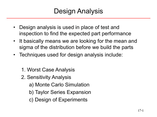
• Shaft 1 +-0.002 • Hole 1 +.003, -.001 • Shaft 2 +-0.002 • Hole 2 +-.003 -.001 • Shaft 3 +-.002 • Hole 3 +-.003 -.001
• Total Worst case is
• If all the parameters represent 3 sigma limits then
– The number of parts bad for one parameter is 0.0026 – Four parameters (0.0026) 4 = 0.00000000000286 (3 in a trillion) – For 20 parameters we get 2 out of 10 58 bad!
17-8
Monte Carlo Analysis
Circuit Example
V I
R2 (2fL)2
(1) V = 5 * Z + 100 (2) R = 1 * Z + 10 (3) f = 5 * Z + 50 (4) L = 0.0008 * Z + .004 (5) Calculate I and plot (6) Repeat 1000’s of times
Design Analysis
• Design analysis is used in place of test and inspection to find the expected part performance
• It basically means we are looking for the mean and sigma of the distribution before we build the parts
ORCAD使用教程

第一章概论本章在简要介绍计算机辅助设计(CAD: Computer Aided Design)和电子设计自动化(EDA: Electronic De sign Auto mation)基本概念的基础上,介绍OrC AD/PSpice软件的功能和特点,并具体说明调用PSpi ce软件进行电路模拟的基本步骤。
1-1 EDA技术和PSpi ce软件1-1-1 CAD和EDA进行电子线路设计,就是根据给定的设计要求,包括功能和特性指标要求,通过各种方法,确定应采用什么样的线路拓扑结构以及线路中各个元器件应采用什么参数值。
有时还需将设计好的线路进一步转换为印刷电路板版图设计。
要完成上述设计任务,一般需经过设计方案提出、验证和修改(若需要的话)三个阶段,有时甚至要经历几个反复,才能完成一个比较好的电路设计。
按照上述三个阶段中完成任务的手段不同,可将电子线路的设计方式分为不同类型。
如果方案的提出、验证和修改都是人工完成的,则称之为人工设计方法。
这是一种传统的设计方法,其中设计方案的验证一般都采用实际搭试验电路的方式进行。
这种方法花费高,效率低。
从70年代开始,随着电子线路设计要求的提高以及计算机的发展,使电子线路设计发生了根本性的变革,出现了CAD和EDA。
1. 计算机辅助设计(CAD)顾名思义,计算机辅助设计是在电子线路设计过程中,借助于计算机来帮助“人”迅速而准确地完成设计任务。
具体地说,由“人”根据设计要求进行总体设计并提出具体的设计方案,然后利用计算机存储量大、运算速度快的特点,对设计方案进行人工难以完成的模拟评价、设计检验和数据处理等工作。
发现有错误或方案不理想时,再重复上述过程。
这就是说,由人和计算机通过CAD这一工作模式共同完成电子线路的设计任务。
2. 电子设计自动化(EDA)CAD技术本身实际上是一种通用技术,在机械、建筑、甚至服装等各种行业中均已得到广泛应用。
但是,在电子行业中,CAD技术不但应用面广,而且发展得最快,在实现设计自动化(DA: Design Automation)方面取得了突破性的进展。
- 1、下载文档前请自行甄别文档内容的完整性,平台不提供额外的编辑、内容补充、找答案等附加服务。
- 2、"仅部分预览"的文档,不可在线预览部分如存在完整性等问题,可反馈申请退款(可完整预览的文档不适用该条件!)。
- 3、如文档侵犯您的权益,请联系客服反馈,我们会尽快为您处理(人工客服工作时间:9:00-18:30)。
Roderick Chapman, Alan Burns, Andy Wellings British Aerospace Dependable Computing Systems Centre, Department of Computer Science, University of York, York, U.K.
Abstract. This paper describes a method for analysing the timing properties of exception handling in Ada. The paper first describes how exceptions are implemented and considers the use of exceptions in the SPARK, Safe/Ada and ANNA subsets. A static analysis technique for reasoning about exception propagation is then presented. We argue that this technique, along with a suitable subset and detailed knowledge of exception implementation can be used to develop an accurate worst-case timing analysis system. The method is illustrated with an example. Finally, our conclusions and plans for further work are presented.
1. Introduction Hard real-time systems are characterised by their need to meet stringent timing requirements. The application of static analysis techniques to determine the worst-case execution time of program fragments has therefore become an important topic. Knowledge of worst-case execution times is essential if schedulability analysis is to be used to guarantee an application's timing properties. Research in this field has concentrated on three topics: computer architecture, language design, and static analysis methods. The latter two topics complement each other: a language-subset for hard realtime programming must be large enough to express useful programs, but small enough to allow efficient and accurate static analysis. In the development of a subset of Ada that is amenable to static timing analysis, certain language features have to be excluded. Access types, recursive subprograms, and unbounded loops are typical of this class since they generally have unbounded or unpredictable execution time. Current timing analysis tools[1-3] have imposed rather Draconian restrictions, only allowing the simplest language constructs. Exceptions are undoubtedly a useful feature of Ada, but they are currently beyond the capabilities of contemporary timing analysis tools. This paper therefore focuses on the development of an analysable subset and static analysis method for exceptions in Ada. In section 2 the implementation of the current exception handling facilities in Ada83 is discussed. It is assumed that the reader is at least familiar with the general style of exception handling in Ada. By considering the implementation of exceptions, difficulties
in their analysis are highlighted. The approaches to exception handling taken in three Ada subsets are also detailed here. Section 3 considers how static analysis techniques can be applied to allow reasoning about exception handling. One such technique “Exception flow analysis” is described in detail. Section 4 proposes a subset of Ada exceptions suitable for use in hard real-time systems and describes our approach for their analysis. Finally, section 5 presents our conclusions and plans for further work. 2. Exception handling in Ada83 Before the timing analysis of exceptions is considered, we must understand how exceptions are implemented in Ada83. The four central topics are: how exceptions are detected, raised, handled and propagated. Within each of these areas, an Ada implementation has a certain amount of freedom - the trade-offs of time, space, complexity, etc. apply here as usual. The sections below look at each of the standard implementation techniques, concentrating on their impact upon timing analysis. A more detailed description is given by Baker and Riccardi[4]. 2.1. Detecting exceptions The job of detecting whether an exception must be raised can be subdivided into the following cases: • Predefined exceptions, implicitly detected. • Predefined exceptions, detected by runtime checks. • User defined exceptions. The first of these classes is the set of predefined exceptions that are detected automatically at runtime by the target computer system. These include the classic cases of divide-by-zero and memory-faults. These are detected by the hardware and are treated as processor exceptions or “traps.” The Ada runtime system must then detect these traps and translate them into the appropriate Ada exception. The second case is simpler. These are the predefined exceptions raised by runtime checks (such as ACCESS_CHECK or INDEX_CHECK) as defined in the Ada LRM. The rules regarding the generation of these runtime checks are complex. Indeed, an implementation is allowed a great deal of freedom in eliminating and optimising checks. Fortunately, the policy employed by the compiler for check generation is largely separate from the mechanisms used to raise and handle the actual exceptions. User defined exceptions are raised explicitly with a raise statement and so are detected by purposely designed code. 2.2. Raising exceptions The job of raising an exception in a task usually falls to the Ada runtime system. Most implementations use a mechanism by which an exception is “posted”ponse to a hardware trap, a check failure, or a raise statement. The important point is that each exception has its own identifier. Some implementations use integers for exception identifiers, some use pointers to the exception’s name - the choice
