MODEL 5100B (中文)-okok-040713-说明书-heibai
华为_MA5100(MA5103) 操作手册_03-维护管理01-23 OAM管理【呕心沥血整理版】
23.3.1 配置 OAM 信元属性
目的
进行 ATM 层 OAM 操作,应首先配置测试区间 OAM 属性,包括 PVC、PVP、信元捕捉 等 OAM 属性。
注意事项
如果从 MA5100 向上行发送 segment 环回信元,则不要在连接的上行方向配置段结点 (segment end point),否则信元没有发送出去就被自己捕获了。同样,下行发送 segment 环回信元,要清除下行方向段结点配置.
Path BIP error events of optical port
: 2488
Section BIP error events of Optical port : 1666025
Corrected HEC error events of optical port : 0
Uncorrected HEC error events of optical port: 0
<frameId/slotId〉{(0)/(0-15)}:0/7
{error-events,cell—capture,loopback,sar-cell}:error—events
感应探头系列5100(Sensorion Series 5100)说明书

5100 | SERIESHERMETICALLY SEALED THERMOSTAT PROBESPECIFICATIONSThe 5100 series is a single pole, single throw, snap-action, hermetically sealed temperature control designed for applications requiring high vibrational resistance in an isolated case. The snap-action disc is located in the very tip of the probe,assuring rapid and true response to temperature. The welded construction of this sealed thermostat ensures meeting thermal shock specifications of MIL-STD-202, method 107, test condition B. In addition,the tube will withstand a pressure exposure limit of 1500 PSI.FeaturesApplicationsIntroduction• Hermetic glass seal, isolated-case only • Ideal for immersion sensing• Multiple mounting and terminations available • UL and CSA recognized component• Hydraulic Systems • Degreasers• Industrial and Portable Compressors • Refrigeration Systems • Generator Sets • Chemical Baths • Engine Coolant• Oil and Transmission ProtectionCONTACT OPERATIONTERMINAL SELECTION1. The standard lead wire (materials) for different temperature ranges are as follows:A. Up to 220°F (104.4°C) = # 18 AWG standed. UL Style 1015/CSA approved. (PVC insulation, color black)B. 221°F to 350°F (105°C to 176.6°C) = #18 AWG stranded. UL Style 1199/CSA approved. (Teflon® TFE insulation, color black)C. 351°F (177.2°C) and above = #18 AWG stranded. UL style 5288/CSA approved. (Composite of Teflon®, ceramic + glass braid, color brown)2. The marking information on each thermostat will include either the name Sensata, contact operation (CLR) close on rise, (OPR) open on rise, top temperature and date code.Same as terminal selection “C”Except 2 Leads48.00 ± 1.00(1219.20 ± 25.40)See note 1 for lead specificationsSame as terminal selection “C”Except 2 Leads24.00 ± 1.00(609.60 ± 25.40)See note 1 for lead specifications Same as terminal selection “C”Except 2 Leads12.00 ± 1.00(304.80 ± 25.40)See note 1 for lead specificationsADBCEFMOUNTING THREAD SELECTION3/8-18 Dryseal PTF-SAE Short1/2-14 Dryseal PTF-SAE Shortwith ‘O’ Ring GrooveTaper Pipe ThreadTaper Pipe ThreadABCTUBE LENGTH SELECTIONABCTEMPERATURE CODES AND TOLERANCENote• Select any temperature in the range of 35°F to 480°F. Standard choices fall on the 5°F increments, for example 140°F, 145°F, 150°F, 155° F... up to 475°F or 480°F • Specify the °F temperature in the part numbering scheme as a three digit code without the ‘°F’ in the part numbe r. For example, for 200°F, put in code ‘200’• Bottom Temperature in °F” equals the “Top Temperature in °F” minus “Nominal Differential in °F”. For example 310°F - 30°F = 280°FNote• The standard tolerance for the top temperature is based on the temperature range the top temperature falls in, please refer to the temperature setting chart, and select the appropriate code for a standard top temperature tolerance• For bottom temperature tolerance a “Y” = minimum trip, which indicates the “reset” trip occurs at or above the lower temperature set point.ORDERING OPTIONSClose contacts on temperature rise, 5100 series, isolated case 6” flying leads, 1/2-14 PTF threads, .698” tube length, 285°F top temperature with a ±10°F standard top tolerance and a standard 40°F differential between top and bottom temperature for temperature range of 251°F to 400°F, differential helps calculate a bottom temperature of 245°F with a standard minimum reset for contacts to close at or above the bottom temperature set point.A, C, N, YSee Temperature Codes and Tolerance TableAmericas+1 (888) 438 2214 *******************Europe, Middle East & Africa +31 (74) 357 8156*******************************Asia Pacific*************************.com China +86 (21) 2306 1500Japan +81 (45) 277 7117Korea +82-10-9218-1179 India +91 (80) 67920890Rest of Asia +886 (2) 27602006 ext 2808Page 5CONTACT USSensata Technologies, Inc. (“Sensata”) data sheets are solely intended to assist designers (“Buyers”) who are developing systems that incorporate Sensata products (also referred to herein as “components”). Buyer understands and agrees that Buyer remains responsible for using its independent analysis, evaluation and judgment in designing Buyer’s systems and products. Sensata data sheets have been created using standard laboratory conditions and engineering practices. Sensata has not conducted any testing other than that specifically described in the published documentation for a particular data sheet. Sensata may make corrections, enhancements, improvements and other changes to its data sheets or components without notice.Buyers are authorized to use Sensata data sheets with the Sensata component(s) identified in each particular data sheet. HOWEVER, NO OTHER LICENSE, EXPRESS OR IMPLIED, BY ESTOPPEL OR OTHERWISE TO ANY OTHER SENSATA INTELLECTUAL PROPERTY RIGHT, AND NO LICENSE TO ANY THIRD PARTY TECHNOLOGY OR INTELLECTUAL PROPERTY RIGHT, IS GRANTED HEREIN. SENSATA DATA SHEETS ARE PROVIDED “AS IS”. SENSATA MAKES NO WARRANTIES OR REPRESENTATIONS WITH REGARD TO THE DATA SHEETS OR USE OF THE DATA SHEETS, EXPRESS, IMPLIED OR STATUTORY, INCLUDING ACCURACY OR COMPLETENESS. SENSATA DISCLAIMS ANY WARRANTY OF TITLE AND ANY IMPLIED WARRANTIES OF MERCHANTABILITY, FITNESS FOR A PARTICULAR PURPOSE, QUIET ENJOYMENT, QUIET POSSESSION, AND NON-INFRINGEMENT OF ANY THIRD PARTY INTELLECTUAL PROPERTY RIGHTS WITH REGARD TO SENSATA DATA SHEETS OR USE THEREOF.All products are sold subject to Sensata’s terms and conditions of sale supplied at SENSATA ASSUMES NO LIABILITY FOR APPLICATIONS ASSISTANCE OR THE DESIGN OF BUYERS’ PRODUCTS. BUYER ACKNOWLEDGES AND AGREES THAT IT IS SOLELY RESPONSIBLE FOR COMPLIANCE WITH ALL LEGAL, REGULATORY AND SAFETY-RELATED REQUIREMENTS CONCERNING ITS PRODUCTS, AND ANY USE OF SENSATA COMPONENTS IN ITS APPLICATIONS, NOTWITHSTANDING ANY APPLICATIONS-RELATED INFORMATIONWARNINGSRISK OF MATERIAL DAMAGE AND HOT ENCLOSURE• The product’s side panels may be hot, allow the product to cool before touching • Follow proper mounting instructions including torque values • Do not allow liquids or foreign objects to enter this productFailure to follow these instructions can result in serious injury, or equipment damage.HAZARD OF ELECTRIC SHOCK, EXPLOSION OR ARCH FLASH • Disconnect all power before installing or working with this equipment • Verify all connections and replace all covers before turning on powerFailure to follow these instructions will result in death or serious injury。
Elcometer 5100 Payne 渗透杯 操作说明书
Elcometer 5100 Payne Permeability Cup Operating InstructionsAll other trademarks acknowledged.© Copyright Elcometer Limited. 2008.All rights reserved. No part of this Document may be reproduced, transmitted, transcribed, stored (in a retrieval system or otherwise) or translated into any language, in any form or by any means (electronic, mechanical, magnetic, optical, manual or otherwise) without the prior written permission of Elcometer Limited.A copy of this Instruction Manual is available for download on our Websitevia /downloads.Doc.No. TMA-0340 Issue 03Text with Cover No: 19611CONTENTSSection Page 1About this instrument. . . . . . . . . . . . . . . . . . . . . . . . . . . . . . . . . . . . . . . . . . . . . . . . . . . . . . . . . . . . . 2 2Taking a measurement. . . . . . . . . . . . . . . . . . . . . . . . . . . . . . . . . . . . . . . . . . . . . . . . . . . . . . . . . . . . 3 3Spare parts & Accessories. . . . . . . . . . . . . . . . . . . . . . . . . . . . . . . . . . . . . . . . . . . . . . . . . . . . . . . . . 5 4The Elcometer 5100 range . . . . . . . . . . . . . . . . . . . . . . . . . . . . . . . . . . . . . . . . . . . . . . . . . . . . . . . . . 6 5Related equipment . . . . . . . . . . . . . . . . . . . . . . . . . . . . . . . . . . . . . . . . . . . . . . . . . . . . . . . . . . . . . . . 61Thank you for your purchase of this Elcometer 5100 Payne Permeability Cup. Welcome to Elcometer. Elcometer are world leaders in the design, manufacture and supply of inspection equipment for coatings and concrete. Our products cover all aspects of coating inspection, from development, through application to post application inspection.This Elcometer 5100 Payne Permeability Cup is a world beating product. With the purchase of this product you now have access to the worldwide service and support network of Elcometer. For more information visit our website at 1 ABOUT THIS INSTRUMENTThe Elcometer 5100 Payne Permeability Cup is a simple instrument which is used to determine the vapour transmission rate of unsupported films of paint, varnish, plastic, paper, etc.The Payne cup is filled with a suitable liquid or dry desiccant and then the film being tested is clamped and sealed across the open end of the cup.The assembly is weighed at the start of the test and again at the end. Any difference between the two weights will be due to water-vapour which has permeated through the film in a given time.The instrument is simple to use and is available in three sizes to suit the requirements of the film being tested. The instrument is manufactured from anodised aluminium.1.1 STANDARDSYour Elcometer 5100 Payne Permeability Cup can be used in accordance with the following National and International Standards:ASTM D1653; ASTM E96; ISO 7783 supersedes NF T30-018.231.2 WHAT THE BOX CONTAINS•Elcometer 5100 Payne Permeability Cup •Storage case •Operating instructionsThe Elcometer 5100 Payne Permeability Cup is packed in acardboard and foam package. Please ensure that thispackaging is disposed of in an environmentally sensitivemanner. Consult your local Environmental Authority for furtherguidance.To maximise the benefits of your new Elcometer 5100please take some time to read these Operating Instructions. Do not hesitate to contact Elcometer or your Elcometer supplier if you have any questions.2 TAKING A MEASUREMENT2.1 TEST PROCEDURE1.Prepare the film to be tested.Figure 1. Elcometer 5100 Payne Permeability Cups4The coating has to be applied a onto a substrate (eg Leneta RP-1K) which allows the film to be removed after it has dried. Silicone coated paper is suitable for many types of coating, however the user of the cup should determine the most suitable substrate for their application.2.Fill the Payne cup with specified liquid or dry desiccant.3.Place the film carefully over the top of the cup ensuring that the film covers the flange of the cup.4.Place the rubber gasket and the sealing ring on the film and secure using the clamps provided.5.Weigh the assembly and record the result in grams (m 1).6.Leave the cup undisturbed for the period of time stated in the standard conditions.7.At regular intervals re-weigh the assembly and record the result in grams (m 2) until linear.8.Calculate the water-vapour transmission rate of the film in grams per sq. metre per day (g/(m 2.d)):P = 240 x ∆m / AWhere ∆m = rate of change in mass in mg/h, and A = area in square centimetres of test piece taken from the following table:a.Elcometer supplies a wide range of manual and motorised film applicators. See “Related equipment” on page 6 for more information.CupArea Elcometer 5100/110 cm²Elcometer 5100/230cm²Elcometer 5100/330cm²52.2 AFTER THE TESTClean the cup and lid.After cleaning, ensure that all materials are removed and that the instrument is dry.3 SPARE PARTS & ACCESSORIESYour Elcometer 5100 Payne Permeability Cup is complete with all the items required to start taking measurements. Over the life of the instrument, replacement rubber gaskets may be required:Rubber gasketPart number Elcometer 5100/1KT005100P001Elcometer 5100/2KT005100P002Elcometer 5100/3KT005100P003Leneta Chart RP-1K (250 pcs)K0004695M112Do not use wire brushes, metal scrapers,metal files or other metallic tools forcleaning.Clean the cup, rubber gasket and sealing ring using a suitable solvent.4 THE ELCOMETER 5100 RANGEModel Volume Area Part Number(cm3)(cm²)(sq. inch)5100/11510 1.55K0005100M2015100/25030 4.65K0005100M2025100/37530 4.65K0005100M2035 RELATED EQUIPMENTIn addition to the Elcometer 5100 Payne Permeability Cup, Elcometer produces a wide range of other coating testing equipment. Users of the Elcometer 5100 Payne Permeability Cup may also benefit from the following Elcometer products:•Elcometer Laboratory Scales•Elcometer Film Applicators•Elcometer Motorised Film ApplicatorsFor further information contact Elcometer or your local supplier.Details of Elcometer offices around the world are given on the outside cover of these operating instructions. Alternatively visit the Elcometer website, 6。
WF-5100 系列纯正波电源用户手册说明书

51001000 Watt Pure Sine Wave Power Inverter,Users ManualDistributed in the USA and Canada by CHENG USA, INC.2021 Aeroplex Drive North. Elkhart, IN. 46514Phone: 574-294-8997, Fax: 547-294-86981. Important Safety Instructions1-1. General Safety Precautions1-1-1. Do not expose the WF-5100 series inverter to rain,snow,spray,bilge or dust.To reduce risk of hazard, do not cover or obstruct the5100 seriesventilation openings. Do not install the WF-Inverter in azero-clearance compartment. Overheating may result.1-1-2. To avoid a risk of fire and electric shock.Make sure that existing wiring is in good electrical condition; and that wire size is not5100 seriesunder sized.Do not operate the WF-inverter withdamaged or substandard wiring.1-1-3. This equipment contains components which can produce arcs or sparks.To prevent fire or explosion do not install in compartmentscontaining batteries or flammable materials or in locations whichrequire ignition protected equipment.This includes any spacecontaining generator, fuel tanks, or joints, fittings, or otherconnection between components of the fuel system.1-2. Precautions When Working with Batteries1-2-1. If battery acid contacts skin or clothing, wash immediately with soap and water. If acid enters eye, immediately flood eye with runningcold water for at least20minutes and get medical attentionimmediately.1-2-2. Never smoke or allow a spark or flame in vicinity of battery.1-2-3. Do not drop a metal tool on the battery. The resulting spark or short-circuit on the battery or other electrical part may cause anexplosion.1-2-4. Remove personal metal items such as rings, bracelets, necklaces, and watches when working with a lead-acid battery.A lead-acid battery produces a short-circuit current high enough toweld a ring or the like to metal, causing a severe burn.2-1. General InformationPlease read all instructions and cautionary marking on this manual before using WF - series Inverter . 51002. Functional CharacteristicsThe WF-5100 Series is a stand alone power inverter with AC run through and is suitable for use in RV, Marine and other applications where clean 115Vac voltage is required.As long as 115Vac utility power is applied to the inverter,115Vac flow through the inverter to appliances. Should 115Vac utility power be cut off, the inverter automatically switches itself to the invert mode providing clean 115Vac. Once the 115Vac utility power is reapplied the inverter switches itself back to the run through mode. Note: Battery must be in place for run through function to work.The WF-5100 Series Inverter is available with12Vdc input (WF-5110H, WF-5110G) or24Vdc input (WF-5120H, WF-5120G). Both have 115Vac 60Hz output.The WF-5100 Series Inverter is also available in two different versions of output wiring:Model: WF-5110H and WF-5120H are hard wired outputs.Model: WF-5110G and WF-5120G have GFCI Receptacles for outputs.This provides a safe and easy way to plug appliances directly into the inverter.2-2. FeaturesProduct :1000 Watt continuous output for electronic appliancesPure sine wave output (THD < 3%) to operate higher -end electronic Equipments . Built in 2 milliseconds transfer time.Built in advance microprocessor to make friendly interface with user .Dual AC GFCI outlets or hard wire AC connection model options .LCD display with all operation statusUL 458 approval and FCC class B .Protection :Battery over voltage and under voltage protections .Over temperature protection .Over load protectionShort Circuit protectionGround fault protection by GFCI receptacle .Reverse polarity protection .AC Output Fuse(15A/600VAC)For Over-Current Protection.This allows the transfer from utility power to invert power to be interruption free, protecting sensitive equipment.2-3. Electrical Performance3. Basically Descriptions3-1Mechanical drawingsHARDWIRE3-2-1. AC Output Fuse:3-2-3. Battery terminals :Connect 12V /24V batteries or other 12V /24V power sources .3-2-4. Connect chassis ground terminal to earth ..Remote port : Connect RJ -11 wiring with remote control unit .3-2-2CAUTION : Do Not Remove Covers.For Continued Fire Protection Replace Only With Specified Type AndRate Fuse. Turns Off The Power Switch Before Replacing Fuse.Refer Servicing To Qualified Personnel.Fuse Information:Manufacturer: LITTELFUSE INCModel Number: KLDR15Fuse Size: 10.3*38.1mm, Rating: 15A/600VAC3-3-1. V entilation :Do not obstruct , allows at least 2 to 3 inches of clearance for airflow . 3-3-2. AC input: Pass Through VoltagePlug into AC source directly: 120Vac, 60Hz, 12 Amps Max .POWERDISPLAYSELETE4. Installation4-1AC Safety Grounding:During the AC wiring installation, AC input and output grounding areconnected to the inverter. The AC input grounding must connect to theincoming grounding of your AC utility sources and the AC output groundingshould go to the grounding point for your loads. (for example, a distributionpanel ground bus ).Neutral Grounding (GFCI):The neutral conductor of the AC output circuit of the Inverter isAutomatically connected to the safety ground during inverter operation.This conforms to National Electrical Code requirements that derived ACsources separately (such as inverter and generators) have their neutralconductors tied to ground in the same way that the neutral conductor fromthe utility is tied to ground at the AC breaker panel.For models configured with a transfer relay, while AC utility powerspresenting and the Inverter is in bypass mode, this connection(neutral of the Inverter's AC output to input safety ground ) is notpresented so that the utility neutral is only connected to ground at yourbreaker panel,as required.4-2Ground Fault Circuit Interrupters (GFCI):Recreational Vehicles Installations (for North American approvals) will requireGFCI protection. All branch circuits connected to the AC output hard wireshould be GFCI protected. Additional electrical codes may require GFCIprotection of certain receptacles in residential installations.While the pure sine wave output of the Inverter is equivalent to thewaveform provided by utilities, compliance with UL standards requires us toUse only GENERAL PROTECHT GROUP INC, test and recommend specific GFCI.Type DG15 ground-fault circuit-interrupter receptacles.Or AMERICAN ELECTRIC DEPOT INC, Type G1501ground-fault circuit-interrupter receptacles. Other types may failto operate properly when connected to this unit.4-3 Hard -wire InstallationTo make AC wiring connections :4-3-1. The AC wiring compartment is located on the front panel of theWF -5110H/WF-5120H .Remove the AC wiring compartment cover to gain access to the AC output hard-wire(pigtails leads).4-3-2. Connect to the AC output wiring of the WF -5110H/WF-5120H AC outputhard-wire(pigtails leads) by using wire connectors, refer to the following: Wire length / gauge Line (L )Black Neutral (N )White Ground Green orBare copper Within 16 feet / AWG # 16~18 16 ~ 32 feet / AWG # 14~164-3-3. After wiring , double check and review all connections to make surethe wires are in correct position and all wires are secure .4-4 Making DC Wiring Connections :Following recommendations for connections between the battery cables and the DC input terminals on the Inverter . T he cables should be made of high quality copper wiring, also keep the cable length as short as possible.I f cables are not of adequate gauge (too small or too long ), theinverter performance will decrease. Please refer to the above chart for proper cable length and gauges. . Battery cable fusing --- A fuse is required by the National Electrical Code (NEC ) to protect the battery and cables , A UL listed DC rated slow blow fuse must be installed in positive battery cable , within 18 inches of the battery .AC output WiringCables should be of adequate gauge for the length of cable being used.WFCO recommends the following cables for an optimum inverter performance . Model NoWireAWG Inline Fuse WF -5110H,5110G# 4 100A WF -5120H,5120G # 6 50A5. Operation:To operate the WF-5100series Inverter, turn it on by using the ON/OFFswitch. The inverter is now ready to deliver AC power to your loads. If youare loading several appliances, turn them on separately after the inverterswitch is on,this process is to avoid the power inverter from delivering thestarting current all at once to the loads.5-1. Controls and indicators:The ON/OFF switch turns on/off the control circuit of the powerinverter. The WF-5100Inverter operates on input voltage ranges as follows:10to15.0VDC for12V models20to30.0VDC for24V modelsYellow LED - indicates battery back up status.Green LED - indicates AC input status.Red LED - indicates inverter failure.LCD Display - indicates operation status.Note: Inverter will not operate on AC input only. A battery must beconnected to the inverter for inverter to operate.6. Warranty Information6-1. WFCO Power Inverter :WFCO extends, to the original owner, a Limited Power Inverter Warrantycommencing from the original date of purchase for a period of two (2) years.This limited warranty is extended specifically for and is limited to RecreationalVehicle application and is only valid in the continental United States, Alaska,Hawaii and the Provinces of Canada. WFCO warrants, to the owner, that itsPower Inverter is free from defects in material and workmanship under normaluse and service based on its intended use and function and is limited to the repair or replacement, at its discretion, of any defective part or defective assembly. Any implied warranties of merchantability and fitness for intended use are limited induration unless applicable State Law provides otherwise. You may have otherright as specified by each individual state.6-2. Exclusions and limitations :The OEM warranty specifically does not apply to the following :Any Power Inverter that has been repaired or altered by anunauthorized person.Any damage caused by misuse, faulty installation, testing, negligence oraccident or any Power Inverter installed in a commercial vehicle.Any Power Inverter whose serial number has been defaced altered orremoved.Any consequential damages arising from the loss of use of the productincluding but not limited to : inconvenience, loss of service, loss of revenue,loss or damage to personal property, cost of all services performed inremoving or replacing the WFCO Power Inverter.6-3. Warranty:Upon determination and validation by the OEM dealer that a WFCO PowerInverter has a defect, the dealer shall contact the WFCO warranty servicenumber (877) 294-8997and obtain a return goods authorization (RGA) number.This number shall appear on all correspondence with warranty service.Upon validation warranty service shall replace the Power Inverter with alike product. The RGA number shall also be placed on the outside of the carton used to return the product for ease of identification. Do not mark on thePower Inverter.。
漏电记录仪 5000 5001 使用说明说明书
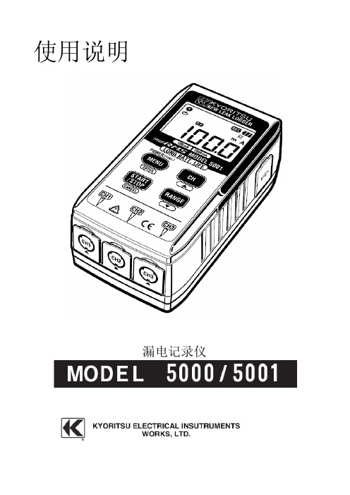
使用说明漏电记录仪目录1.安全警告2.特色3.规格4.各部分名称4-1面板4-2LCD显示屏4-3LCD提示一览5.测定记录前的准备工作5-1电源ON/OFF5-2电池电压的确认5-3自动关机5-4连接传感器5-5仪器设置5-6最大记录时间和记录件数6.操作说明6-1连续记录模式6-2事件记录模式6-3区间最大值记录模式6-4截获记录模式7.测定7-1电流测试7-2测试方法和记录方式8.记录操作9.菜单控制(操作,项目)9-1菜单控制9-2设定值变更9-3菜单流程图10.数据传输11.更换电池本仪器设计、制造和测试均符合IEC61010安全标准。
本说明书包含了警告和安全指示,使用时请严格遵守,以确保使用者的操作安全及仪器安全。
使用前请详读说明书。
警告●使用前请仔细阅读并领回操作指南中所规定的内容。
●无论何时必须遵守手册的要求,并保存好手册,使之随时能供作参考。
●确定本机只在特定场合下使用。
●确认已理解并须严格遵守本手册中所有的安全说明。
请勿必严格遵守以上说明,如违反指示进行操作,可能会导致事故及人身伤害的发生。
说明书中符号,提醒使用者必须参考手册中的相关内容,以确保操作的安全性。
请仔细阅读内容。
危险是表示无视此标志进行错误操作时,造成死亡或重伤的危险性极高。
警告是表示无视此标志进行错误操作时,造成死亡或重伤的危险性极高。
注意是表示无视此标志进行错误操作时,造成人身事故及仪表损害的危险●请勿在AC300V的对地电压回路中使用。
●请勿在易燃易爆环境下进行测量,否则使用时可能会产生火花,以致引起爆炸。
●测量钳口采用不易造成被测物短路的设计。
但测量非绝缘导线时请注意避免短路。
●请勿在仪器或手沾湿的情形下做任何测量。
●请勿输入超过测试范围的最大允许值。
●请勿在测量时打开电池盖或仪器外壳。
●使用前请确认电源正常。
警告●如果仪器发现任何异常(如导线破损、机壳裂缝等),请勿进行测试。
●请勿随意更换部件或对仪器做任何修改,如需维修请联系维修中心或经销商。
卡西欧G-shock MTG-510双显电子表说明书

Module No. 23392339-1WORLD TIME MODEThe World Time Mode shows you the current time in 27cities (29 time zones) around the world.•For full information on city codes, see the “CITY CODETABLE”.•The time setting of the Timekeeping Mode and the World Time Mode are synchronized. Whenever you change the time setting for any city in the Timekeeping Mode,the settings of all World Time cities are changed ac-cordingly.To select a World Time City and view its time1.In the World Time Mode, press D to scroll forward through the city codes (time zones). Holding down D scrolls at high speed.2.When the city code you want is on the display, press A to view its current time.parallel to the left or right. Make sure that the back of your hand is parallel to the ground.TIMEKEEPING MODE•Press D to toggle the display between the date screen (day of the week, month, day) and the time screen (hour,minutes, seconds).To set the time and date1.While in the Timekeeping Mode, hold down A until the seconds digits flash on the display, indicating the set-ting screen.2.Press C to move the flashing in the sequence shown below.3.While the seconds setting is selected (flashing), press D to reset it to 00. If you press D while the seconds setting is in the range of 30 to 59, the seconds are re-set to 00 and 1 is added to the minutes. If the seconds setting is in the range of 00 to 29, the minutes count is unchanged.•Static electricity or magnetic force can interfere with proper operation of the auto backlight function. If the auto backlight does not illuminate, try moving the watch back to the starting position (parallel with the ground) and then tilt it back toward you again. If this does not work, drop your arm all the way down so it hangs at your side, and then bring it back up again.•Under certain conditions the backlight may not light until about one second or less after turning the face of the watch towards you. This does not necessarily indicate malfunction of the backlight.To switch the auto light switch function on and offIn the Timekeeping Mode, hold down D for one or two seconds to turn the auto light•The auto light switch indicator is shown on the display in all modes while the auto light switch function is on.•In order to protect against running down the battery, the auto light switch function is automatically turned off approximately six hours after you turn it on. Repeat the above procedure to turn the auto light switch function back on if you want.•Pressing B at any time illuminates the display, regardless of the auto light switch’s on/off setting.Caution•The backlight of this watch employs an electro-luminescent (EL) light, which loses its illuminating power after very long term use.•Frequent use of the backlight shortens the battery life.•The watch emits an audible sound whenever the display is illuminated. This is be-cause the EL light vibrates slightly when lit. It does not indicate malfunction of the watch.Warning!•Never try to read your watch when mountain climbing or hiking in areas that are dark or in areas with poor footing. Doing so is dangerous and can result in serious personal injury.•Never try to read your watch when running where there is the danger of acci-dents, especially in locations where there might be vehicular or pedestrian traffic. Doing so is dangerous and can result in serious personal injury.•Never try to read your watch when riding on a bicycle or when operating a motorcycle or any other motor vehicle. Doing so is dangerous and can result in a traffic accident and serious personal injury.•When you are wearing the watch, make sure that its auto light switch function is turned off before riding on a bicycle or operating a motorcycle or any other motor vehicle.Sudden and unintended operation of the auto light switch can create a dis-traction, which can result in a traffic accident and serious personal injury.GENERAL GUIDE•Press C to change from mode to mode.•Pressing B in any mode illuminates the digital display for about 1.5 seconds. The backlight is disabled while a setting screen is on the display.•If you do not perform any operation for a few minutes while a setting screen (with flashing digits) is on the display, the watch automatically exits the setting screen.•While the DST ∗ (Daylight Saving Time) setting is selected, press D to toggle it on and off. If you turn the DST on, the DST on indicator appears on the display.•The DST on/off setting you make for the city code that is currently selected in the Timekeeping Mode (your home time city) is also applied to that city code in the World Time Mode.•While the city codes setting is selected, use D (+) and B (–) to scroll thorough the available codes until the one you want to use as your home time city is displayed.•For full information on city codes, see the “CITY CODE TABLE”.•While the 12/24-hour setting is selected, press D to switch between the two for-mats.• With 12-hour timekeeping, times between midnight and noon are indicated by A (am), while times between noon and midnight are indicated by P (pm).• The 24H indicator is on the display while 24-hour timekeeping is selected.• While any other setting is selected (flashing), press D (+) or B (–) to change it.Holding down either button changes the setting at high speed.4. After you make the settings you want, press A to exit the setting screen.•The day of the week is automatically set in accordance with the date.•The date can be set within the range of January 1, 2000 to December 31, 2039.•The watch’s built-in full automatic calendar automatically makes allowances for dif-ferent month lengths and leap years. Once you set the date, there should be no reason to change it except after the replacement of the watch’s battery.∗Daylight Saving Time (DST ), which is also sometimes called “summer time” ad-vances the time for one hour, as is the custom in some areas during the summer.Remember that not all countries or even local areas use Daylight Saving Time.ABOUT THE BACKLIGHTAbout the Auto Light Switch FunctionWhen the auto light switch function is turned on, the backlight automatically turns on for about 1.5 seconds under the conditions described below. Avoid wearing the watch on the inside of your wrist. Doing so causes the auto light switch to operate when not needed, which shortens battery life.Parallel to groundMore than 15 degrees More than 15 degrees indicator 2City Code zone3. While the time screen is on the display, press D to switches back to the city code screen.•At this point you could press D again to scroll through city codes.Daylight Saving Time (DST)Daylight Saving Time automatically advances the time setting by one hour from Standard Time. You can make individual Daylight Saving Time settings for each city code (time zone). Remember that not all countries or even local areas use Daylight Saving Time.To switch between Standard Time and Daylight Saving Time1.In the World Time Mode, use D to display the city code (time zone) whose stan-dard time/daylight saving time setting you want to change.2.Hold down A toggle between Daylight Saving Time and Standard Time.•The DST indicator appears on the display whenever you display a city code for which daylight saving time is turned on.TELEMEMO MODEThe Telememo Mode lets you store up to 30 records, each• The record on the display when you exit the Telememo Mode appears first the next time you enter the Telememo Mode.To input a new Telememo record1.In the Telememo Mode, if the message “NO-DATA ” is not on the display, press D and B at the same time. This causes the blank screen to appear.•If the blank screen does not appear when you press D and B , it means that memory is full. To store another record, you will first have to delete a record stored in memory.2.Hold down A and a cursor appears on the display.e D (+) and B (–) to scroll through characters at the current cursor position.Characters scroll in the sequence shown below.•Holding down D or B scrolls at high speed.4.When the character you want is at the current cursor position, press C to move the cursor to the right.5.Repeat the steps 3 and 4 to input the rest of the characters.6.After you input the name, use C to move the cursor to the right until the number input screen “-----” appears.•You can input up to eight characters for the name, though only six characters are visible at a time. If the name you input has fewer than eight characters, use C to move the cursor to the eighth space (which means you would press C three times after inputting a five-character name).•Pressing C again while the cursor is at the eighth space changes to the number input screen. When the cursor is at the 14th digit of the number input screen, press-ing C causes the name input screen to appear again.eD (+) and B (–) to scroll through characters (hyphen, numbers, space) at the current cursor position on the number screen. Characters scroll in the sequence shown below.•Holding down D or B scrolls characters at high speed.8.When the character you want is at the cursor position, press C to move the cursor to the right.9.Repeat steps 7 and 8 to input the rest of the numbers you want.•You can input up to 14 digits for the number.10.After inputting the name and number of the record, press A to store it.•The message “SORT” appears on the display for a few moments after you press A to indicate that the watch is sorting records.•After the record is sorted, the cursor appears in the display, ready for input.11.Input the next record or press A to exit the setting screen.•The display can show only six name characters or nine number digits at a time.Longer names and numbers scroll continuously from right to left. The symbol “ ”indicates that the character or digit to the left is the last, and the character or digit to the right is the first.•Pressing D while a name is scrolling on the display jumps to the first character of the name. Scrolling resumes from there.•Pressing A while a number is scrolling on the display jumps to the first digit of the number. Scrolling resumes from there.To recall Telememo data1.In the Telememo Mode, press D to scroll forward through the names of the stored records.•Holding down D scrolls through the names at high speed.2.When the name for the record you want is on the display, press A to view its number.3. Pressing D while a number screen is on the display returns to the name screen.•At this point you could press D again to scroll through names.To edit Telememo data items1.In the Telememo Mode, press D to scroll forward through the names of the stored records.•Holding down D scrolls through the names at high speed.2.When the name for the record you want is on the display, hold down A until the cursor appears in the display.e C to move the cursor to the character you want to change.e D (+) and B (–) to change the character.•See step 3 of “To input a new Telememo record” for information on inputting name characters, and step 7 for inputting number characters.5.After making the changes that you want, press A to store them and exit the set-ting screen.•The message “SORT” appears on the display for a few moments after you press A to indicate that the watch is sorting records.To delete Telememo data1.In the Telememo Mode, press D to scroll forward through the names of the stored records.•Holding down D scrolls through the names at high speed.2.When the name for the record you want is on the display, hold down A until the cursor appears in the display.3.Press D and B at the same time. The message “CLEAR” appears in the display,indicating that the record was deleted.•After the record is deleted, the cursor appears in the display, ready for input.4.Input a record or press A to exit the setting screen.ALARM MODEYou can set up to five daily alarms. When the Daily Alarm is turned on, the alarm sounds for 20 seconds at the pre-set time each day. Press any button to stop the alarm after it starts to sound. When the Hourly Time Signal is turned on, the watch beeps every hour on the hour.To set the alarm time1.While in the Alarm Mode, press D to display the num-ber of the alarm you want to set.2.Hold down A until the hour digits flash on the display, indicating the setting screen.•At this time, the alarm is turned on automatically.3.Press C to move the flashing in the sequence shown below.e D (+) and B (–) to change the setting. Holding down either button changes the setting at high speed.5.After you set the alarm time, press A to exit the setting screen.•The format (12-hour and 24-hour) of the alarm time matches the format you select in the Timekeeping Mode.•When setting the alarm time using the 12-hour format, take care to set the time correctly as morning or afternoon.To stop the alarm•Press any button to stop the alarm after it starts to sound.To turn a daily Alarm or the Hourly Time Signal on and offe D to display the alarm you want to turn on or off, or the screen for turning the Hourly Time Signal on or off.2.Press A to toggle the displayed alarm or Hourly Time Signal on and off.•the currently displayed alarm. In all other modes, the alarm on indicator appears when any one of the five alarms is turned on. The alarm on indicator is not dis-played in other modes when all alarms are turned off.Hourly Time •The Hourly Time Signal indicator is displayed in all modes when the Hourly Time Signal is turned on.To test the alarmIn the Alarm Mode, hold down D to sound the alarm.•The alarm test does not work while the Alarm Mode setting screen is on the display.•Holding down D to test the alarm also advances to the next alarm number.STOPWATCH MODEThe Stopwatch Mode lets you measure elapsed time, split times, and two finishes. The range of the stopwatch is 59minutes, 59.99 seconds. You can use the EL backlight by pressing B at any time while the stopwatch is operating.Elapsed time measurementD D D D A StartStopRe-startStopClearSplit time measurementD A A D A Start SplitSplit release Stop ClearSplit time and 1st-2nd place timesD ADAAStartSplitStopSplit release ClearFirst runner finishes.Second runner finishes.Record time of first runner.Record time of second runner.®®®®®®®®®®®®HAND SETTING MODEWhen the analog setting does not match the time shown on the digital display, use this mode to correct the analog setting.1.Hold down A while in the Hand Setting Mode until the message “SET” start to flash on the display.2.Each press of D advances the hands 20 seconds. Hold-ing down D advances the hand at high speed.•Pressing B while holding down D causes the handsetting to change at high speed, even if you release thebuttons. Press any key to stop.• The analog time setting does not stop automatically when it reaches the current time. You must stop the hands manu-ally.• Note that the hands can be advanced only and cannot be moved back. Take care so you do not go past the setting you want to make.3.After you set the analog time, press A to exit the setting screen.• Depending on your timing when you operate the D button, the above operation can cause the minute hand timing to become late. If this happens, repeat the above operation to correct the minute hand timing.CITY CODE TABLE–11–11–10HNLHONOLULUPAPEETE –9ANCANCHORAGENOME–8LAX LOS ANGELESSAN FRANCISCO , LAS VEGAS,VANCOUVER, SEATTLE, DAWSON CITY–7DEN DENVER EL PASO, EDMONTONHOUSTON, DALLAS/FORT WORTH,–6CHICHICAGO NEW ORLEANS, MEXICO CITY,WINNIPEGMONTREAL, DETROIT, MIAMI, BOSTON,–5NYC NEW YORK PANAMA CITY, HAVANA, LIMA,BOGOTA–4CCS CARACAS LA PAZ, SANTIAGO, PORT OF SPAIN–3RIO RIO DE JANEIROSAO PAULO, BUENOS AIRES, BRASILIA,MONTEVIDEO–2–02–1–01 0GMT 0LONLONDONDUBLIN, LISBON, CASABLANCA,DAKAR, ABIDJANMILAN, ROME, MADRID, AMSTERDAM,+1PAR PARIS ALGIERS, HAMBURG, FRANKFURT,VIENNA, STOCKHOLM, BERLIN +2CAI CAIROATHENS, HELSINKI, ISTANBUL,JRS JERUSALEM BEIRUT, DAMASCUS, CAPE TOWN +3JED JEDDAH MOSCOW, KUWAIT, RIYADH, ADEN,ADDIS ABABA, NAIROBI +3.5THR TEHRAN SHIRAZ+4DXB DUBAI ABU DHABI, MUSCAT +4.5KBL KABUL +5KHI KARACHI MALE+5.5DEL DELHI MUMBAI, CALCUTTA +6DAC DHAKA COLOMBO+6.5RGN YANGON +7BKKBANGKOKJAKARTA, PHNOM PENH, HANOI,VIENTIANESINGAPORE, KUALA LUMPUR,+8HKG HONG KONG BEIJING, TAIPEI, MANILA, PERTH,ULAANBAATAR+9TYO TOKYO SEOUL, PYONGYANG +9.5ADL ADELAIDE DARWIN+10SYD SYDNEY MELBOURNE, GUAM, RABAUL +11NOU NOUMEAPORT VILA+12WLGWELLINGTONCHRISTCHURCH, NADI, NAURU ISLAND*Based on data as of June 2000.GMT City City Other major cities in same time zonedifferential CodeCHARACTER LIST。
氢能应用仪表产品解决方案说明书

销售要约未能、不当选择或不当使用此处描述的产品和/或系统或相关物品可能导致死亡、人身伤害和财产损失。
对于具有技术专业知识的用户来说,派克汉尼汾公司、其子公司或授权分销商提供的本文档和其他信息为之提供了进一步调查所需的产品和/或系统选项。
分析应用程序的所有方面并查看当前产品目录中有关产品或系统的信息非常重要。
由于这些产品或系统的操作条件和应用场景的多样性,用户通过自己的分析和测试,全权负责产品和系统的最终选择,并确保应用的所有性能、安全和警告要求得到满足。
本文所述产品(包括但不限于产品功能、规格、设计、可用性和定价)可由派克汉尼汾公司及其子公司随时更改,恕不另行通知。
本文档中所述产品可由Parker Hannifin 、其子公司或授权分销商销售。
派克签订的任何销售合同均受派克标准销售条款和条件中规定的条款管辖(可根据要求提供复印件)中规定的条款约束。
警告目录车载设备 - EC-79认证部件30到350 bar(435 - 5,076 psi)的应用 (6)双卡套接头 - A-LOK®系列 (6)700 bar(10,152 psi)以下的应用 (7)中压接头 - C&T形式 - Autoclave Engineers® (7)中压针阀SM系列 - Autoclave Engineers® (7)中压钢管 - Autoclave Engineers® (7)加氢站应用 - 符合ISO 19880-3认证产品中压针阀20SM系列 - Autoclave Engineers® (8)中压O形圈密封形式的单向阀CXO系列 - Autoclave Engineers® (8)一般氢气应用414 bar (6,000 psi)以下的应用 (10)双卡套接头 - A-LOK®系列 (10)截止阀 - B系列 - 隔断和方向控制阀门 (10)线性过滤器 - F系列 (10)单向阀 - CO系列 - 方向控制阀 (11)流路切换系统 - R-Max TM Gen II系列 (11)模块化样品预处理系统 - IntraFlow TM系列 (11)调压阀 - IR4000和IR6000系列 (11)过流关断流阀 - FS190系列 (11)1,380 bar(20,000 psi)以下的应用 (12)中压双卡套接头 - MPI TM系列 (12)中压接头 - C&T形式 - Parker Autoclave Engineers® (12)永久推入式接头 - Phastite®系列 (12)截止阀 - Hi-Pro系列 - 隔断阀 (12)截止阀 - HB系列 - 隔断阀 (12)针阀MAN - MPI TM系列 (13)中压针阀15SM和20SM系列 - Autoclave Engineers® (13)中压O形圈形式单向阀CXO系列 - Autoclave Engineers® (13)中压O形圈形式单向阀MAC - MPI TM系列 (13)DBB双隔断/排放阀组 - 20DBNV系列 - Autoclave Engineers® (13)泄压阀 - 软阀座RVS系列 - Autoclave Engineers® (14)中压钢管 - MPI TM系列 (14)中压执行器 - Autoclave Engineers® (14)中压转换接头 - Autoclave Engineers® (14)中压零配件 - Autoclave Engineers® (14)低温/LH2液氢应用截止阀 - 不锈钢阀体带铜内件 - Bestobell Industrial (16)截止阀 - 不锈钢 - Bestobell Marine (16)气动截止阀 - 不锈钢阀体带铜内件 - Bestobell Industrial (16)气动截止阀 - 不锈钢 - Bestobell Marine (16)提升式单向阀 - 不锈钢阀体带青铜内件 - Bestobell Industrial (17)提升式单向阀 - 不锈钢 - Bestobell Marine (17)摆动式单向阀 - 不锈钢 - Bestobell Marine (17)手动闸阀 - Bestobell Industrial (17)气动闸阀 - 气动轮胎设计 - Bestobell Industrial (17)助力推动能源变革的可靠伙伴根据2009年1月14日欧洲议会和理事会第79/2009号法规的规定,真空30350700车载设备双卡套接头 - A-LOK®系列 通过EC-79测试Parker Autoclave Engineers®:中压C&T 接头 通过EC-79测试中压针阀-SM 系列 通过EC-79测试中压钢管 通过EC-79测试通过E C -79测试一般氢气应用双卡套接头 - A-LOK®系列永久推入式接头 - Phastite®系列截止阀 - B 系列截止阀 - Hi-Pro 系列截止阀 - HB 系列线性过滤器 - F 系列单向阀 - CO 系列流路切换系统 - R-Max II模块化样品预处理系统 - IntraFlow TM 系列调压阀 - IR4000和IR6000系列过流关断阀 - FS190系列低温/LH 2液氢应用Bestobell 低温阀:截止阀提升式单向阀摆动式单向阀手动闸阀气动闸阀一般氢气车载设备ONS TATIO 派克正在为各种氢能应用提供多元化的解决方案,支持全球减碳、脱碳愿景。
华为_MA5100(MA5103) 操作手册_01-基础配置01-04 单板管理
说明 SPL 板是无源板,无需与背板接触即可正常工作。除 SPL 板外,其它业务板如果插在空槽位则 系统会自动进行注册并识别出单板类型。SPL 板不能自动注册,必需使用 board add 增加。
通过 show board 命令可以查询单板信息。 当只输入框号时,查询该框的整体信息,包括整框的所有槽位上的单板名称、单
Normal
H511E8FS
-
14 EMPTY
-
-
-
-
15 EMPTY
-
-
-
-
---- -------- -------- -------------- ------------------- -------------------
4.3 删除单板
目的
删除不再需要的单板。
注意事项
删除单板时需注意:
删除单板是不可恢复的操作,单板的数据将被全部清除。 如果删除正常运行的单板,可先将单板禁止后再删除,可提高安全性。 主控板不能进行删除操作。
E8FS
e8fs
提供 8 路 FE 电接口(RJ-45 接口, LAND、EVMA 固定在单板上,不能更换)
O2GS
o2gs
提供 2 路 GE 光接口(支持单模和 EVMB、MMXV 双模)
O2FS
o2fs
提供 2 路 FE 光接口(支持单模和 EVMB、MMXV 双模)
E4FA
e4fa
提供 2 路 FE 电接口
使用单板 AIUA、AIUL AIUA、AIUL AIUA、AIUL AIUA、AIUL AIUL AIUL FRCA、CESC、 CESE FRCB、CESD LAND、EVMA LAND、EVMA LAND、EVMA LAND、EVMA
拉布韦特自动化臂型机器人1000型号5100说明书
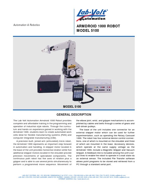
GENERAL DESCRIPTIONAutomation &RoboticsARMDROID 1000 ROBOT MODEL 5100The Lab-Volt Automation Armdroid 1000 Robot provides complete and affordable training in the programming and operation of industrial style robots. Through the curricu-lum and hands-on experience gained in working with the Armdroid 1000, students learn to create automated work cells ideal for flexible manufacturing systems (FMS) and computer integrated manufacturing (CIM).A precision-built, joined arm (articulated) micro robot,the Armdroid 1000 represents an important step forward in automation and handling. A stepper motor located in the base of the unit provides horizontal rotation while five additional stepper motors located in the shoulder provide precision movements of specialized components. The continuous path robot has five axes of rotation plus a gripper and is able to use several joints simultaneously to perform a programmed move sequence. Movement ofLAB-VOLT SYSTEMS, INC., P .O. BOX 686, FARMINGDALE, NJ 07727, U.S.A., (732) 938-2000 or 800-LAB-VOLT,FAX:(732)774-8573,E-MAIL:**************LAB-VOLT LTD/LTEE, 2120 RUE LAVOISIER, SAINTE-FOY , QUÉBEC, CANADA, G1N 4B1, (418) 681-6346 or 800-LAB-VOLT,FAX:(418)687-4014,E-MAIL:**************INTERNET ADDRESS: the elbow joint, wrist, and gripper mechanisms is accom-plished by cables and belts through a series of gears and belt-driven pulleys.The base of the unit includes one connector for an external stepper motor which can be used for further experimentation, such as operating the Rotary Carousel 1000. The robot has four external device control connec-tions, one of which is mounted on the shoulder and three of which are mounted in the base. Accessory devices,which operate at the same supply voltage as the Armdroid 1000, include a Magnetic Gripper and Vacuum Gripper. A feedback line is included among the unit’s out-put lines to enable the robot to operate in a wait state via an external sensor. The included File Transfer software allows point programs to be stored and retrieved from aPC through a standard serial port.STRUCTURAL FEATURESBaseThe base supports the arm mechanism and houses the printed circuit control boards and motor that provides the rotation of the shoulder. A mechanical stop on the base prevents over-rotation of the shoulder. The robot base also houses four TTL outputs and three 12 V relay switch ports for control of external devices.ShoulderRotating on the base, the shoulder houses the five motors associated with the gears and belts that move the other parts of the arm. The shoulder movement spans 170 degrees. A mechanical stop prevents the shoulder from over-travel.Upper ArmAttached to the shoulder, the lower end of the upper arm carries the gears and pulleys that drive the elbow, wrist,and gripper. Driven by its own stepper motor and pivot-ing from the shoulder joint, the upper arm contains gears that mesh with the reduction gears of the shoulder to provide up and down movement at a maximum of 190degrees.ForearmThe forearm attaches from the elbow joint and extends to the wrist, moving a maximum of 200 degrees up or down. The structure of the forearm allows the gripper pul-ley block, housed in the forearms center, to move back and forth, which opens or closes the gripper.Wrist and GripperThe wrist and gripper work together to pick up items and move them to a programmed location. The wrist moves up or down to control the two-fingered gripper that can rotate in a 360 degree clockwise or counterclockwise direction. The fingers of the gripper, which are fitted with rubber tips that enable it to grab onto items with smooth surfaces, move in an “open” or “close” motion. The wrist gears are moved by drive belts attached to gear and toothed belt assemblies using two dedicated wrist step-per motors. The gear assemblies of the stepper motor can be moved in opposite directions from one another to cause the gripper to roll or twist, or they can be moved in the same direction to pitch the gripper in an up or down direction.Stepper MotorsThe Armdroid 1000 stepper motors take 200 steps per revolution at 1.8 degrees per step motion.TEACH PENDANT 1001The Teach Pendant 1001 provides the control for the Armdroid 1000. It has a four-line, 20-character LCD dis-play for feedback to the operator. The Teach Pendant has a serial port for uploading and downloading a point pro-gram to a computer. The interface box has standard tip jacks for 6TTL inputs, and 2 interrupt lines on the inter-face box (one for the system and one for safety.)ROBOT COURSEWAREBasic instruction in Lab-Volt Automation robotics involves step-by-step directions in the setup and opera-tion of the Armdroid 1000. These directions are provided•Creating a Program •Obstacles •Robot Speeds •Efficiency•Simulating an Industrial Activity •Simulating a Welding Operation •Using a Wait Point•Combining Common Commands •Simulating a Washing Operation •Creating a Shell Game •Using a Feeder•Using the Rotary CarouselUser Manual•Introduction to Robotics•Mechanical and Electrical Components •Connecting the Armdroid 1000•Teach Pendant 1001•Teach Pendant 1001 File Transfer Software •End Effector •Parts Feeders•Rotary Carousel 1000•Conveyor Belt 1000Student Manual•Robotics Pretest•Using the Armdroid 1000in manuals that enable students to get started immedi-ately and include the following topics:TEACH PENDANT FEATURES•Four-line, 20-character command and message display•One 9-pin serial port to upload and download point programs from a PC•Standard tip jacks for six TTL compatible inputs and two interrupt lines on the interface box.LAB-VOLT AUTOMATION®ARMDROID 1000 ROBOT MODEL 5100ROTARY CAROUSEL 10005113-00The Rotary Carousel 1000 has a 12” platter mounted on a 4” x 7” x 7” base. It is controlled by stepper motor open loop control via the external stepper motor connector in the base of the Armdroid 1000.OPTIONALACCESSORIESBELT CONVEYOR 1000MODEL 5118-00Used in material handling experiments with the Armdroid 1000 and Armdroid 2001, the conveyor has a self-con-tained power supply and electronic interface. The control panel has three input connectors for interfacing the con-veyor with the Armdroid robots, or as a stand- alone unit.The inputs enable the motor power, stepper motor clock signal, and the direction of the belt movement to be remotely controlled. Overall dimensions are 38” x 4.5” x 5.5”.Gravity Feeder (Flat)MODEL 5119-00The Gravity Feeder (Flat) is used in exercises that require flat stock. It has a sensor switch and feedback cables for connection to the Armdroid 1000 through the Teach Pendant 1001. Movable magnetic guideways allow for a wide range of stock sizes.Gravity Feeder (Cylinder)MODEL 5121-00The Gravity Feeder (Cylinder) is used in exercises that require cylindrical stock. It as a sensor switch and feed-back cables for connection to the Armdroid 1000 throughthe Teach Pendant 1001.ROTARY CAROUSEL 10005113-00BELT CONVEYOR 1000MODEL 5118-00GRAVITY FEEDER (FLAT)MODEL 5119-00GRAVITY FEEDER (CYLINDER)MODEL 5121-00LAB-VOLT AUTOMATION®ARMDROID1000 ROBOT MODEL 5100REQUIRED EQUIPMENTDescription Model # Armdroid 1000 (120V).............................................................................................................................................5100-10 Includes robot, Teach Pendant 1001, power supply, File Transfer software, User Guide, Student Manual, and Instructor GuideArmdroid 1000 (220V).............................................................................................................................................5100-15 Includes robot, Teach Pendant 1001, power supply, File Transfer software, User Guide, Student Manual, and Instructor GuideOPTIONAL CURRICULUM ACCESSORIESDescription Model # Armdroid 1000 User Guide..............................................................................................................................TM-5152-00 Armdroid 1000 Student Manual.......................................................................................................................TM-5166-00 Armdroid 1000 Instructor Guide......................................................................................................................TM-5166-10 Conveyor Belt 1000 (120V).....................................................................................................................................5118-00 Conveyor Belt 1000 (220V).....................................................................................................................................5118-05 Gravity Feeder Flat.................................................................................................................................................5119-00 Gravity Feeder Cylinder..........................................................................................................................................5121-00 Pneumatic Stock Feeder (2” x 2” x 1/2”)...............................................................................................................5122-00 Magnetic Gripper....................................................................................................................................................5111-00 Two-Finger Gripper (For replacement only)............................................................................................................5112-00 Pneumatic Feeder, Round......................................................................................................................................5142-00 Rotary Carousel, 1000............................................................................................................................................5113-00 Vacuum Gripper......................................................................................................................................................5115-00 Relay Kit #1 – 1 solenoid........................................................................................................................................5125-00 Includes box and connecting cables to control 1 external devicePneumatic Supply System for Flexible Manufacturing Systems (120V)..........................................................AX-5169-00 Armdroid 1000 Grid Sheet..............................................................................................................................TE-95089-00MECHANICAL SPECIFICATIONS*Mechanical Arm Construction..................................................................................................................................................Articulated arm Number of axes...............................................................................................................................................5 plus gripper Load capacity...............................................................................................................................................................16 oz Reach..............................................................................................................................................................................17”Repeatability.............................................................................................................................................................0.125 in Maximum speed......................................................................................................................................................6 in /sec Actuators.............................................................................................................................................6 DC stepper motors Working EnvelopeBase .............................................................................................................................................................................320°Shoulder joint.................................................................................................................................................................170°Elbow joint.....................................................................................................................................................................190°Pitch joint ......................................................................................................................................................................200°Roll joint ........................................................................................................................................................................360°Transmission......................................................................................................................................Gears and timing belts Weight........................................................................................................................................................................10.5 lb * Specifications are subject to change without notice.Lab-Volt reserves the right to make product improvements at any time and without notice and is not responsible for typographical errors. Lab-Volt recognizes all product names used herein as trademarks or registered trademarks of their respective holders. © Copyright Lab-Volt Systems, Inc., 1998. PRINTED IN THE USA.TA94012-00 Rev. C。
Philips Sonicare ProtectiveClean 5100 电动牙刷说明书

Sonic electrictoothbrushProtectiveClean5100Built-in pressure sensor3 modes1 x BrushSync featureTravel caseHX6859/17Healthier gums. Gently does it.Improve gum health up to 100% more than a manualFeel the difference of a gentle clean with our Pressure Sensor while improving yourgum health up to 100% more vs a manual toothbrushProven to improve oral healthImproves gum health by up to 100%*Safe & gentle on sensitive areas, orthodontics & dental workOptimize your brushingChoose from three modesInnovative technologyLets you know if you’re pressing too hardConnects smart brush handle and smart brush headsAlways know when to replace your brush headsPhilips Sonicare's advanced sonic technologyDesigned around youEncouragement to brush thoroughlyMakes traveling easier for youHighlightsImproves gum healthDensely-packed, high-quality bristles give you an extra gentle brushing to remove plaquealong the gumline to improve gum health up to 100% more than a manual toothbrush. And, the specially curved power tip makes reaching the teeth at the back of your mouth a breeze.Three modesThis toothbrush allows you to customize your brushing to your own needs, with a choice of three modes. Clean mode is standard forsuperior cleaning. White is the ideal mode for removing surface stains. And Gum Care mode adds an extra minute of reduced-power brushing, so you can gently massage your gums.Safe and gentleYou can be sure of a safe brushing experience:our sonic technology is suitable for use with braces, fillings, crowns, and veneers, and helps prevent cavities and improve gum health.The only true sonic technologyPhilips Sonicare's advanced sonic technology pulses water between teeth, and its brushstrokes break up plaque and sweep it away for an exceptional daily clean.Monitor your brushing pressure Brushing too hard can damage your teeth and gums. To prevent this, your Philips Sonicare ProtectiveClean emits a gentle pulsing sound to remind you to ease off on the pressure.BrushSync technologyA microchip-enabled technology that detects and synchronizes the smart brush head with the smart handle. The smart handle and smart brush head pair is a powerful combination that enables Smart replacement reminders.BrushSync replacement reminderAll brush heads wear out over time. But our BrushSync technology tracks how long you've been using your brush head for, and how hard you've been brushing. When it's time toreplace it, a light on your handle and a short beep will let you know. That way, you can be sure your brush head is doing a good job.Helpful timersNeed an electric toothbrush with a timer? Our QuadPacer lets you know when you've spent just the right amount of time cleaning each part of your mouth, while our Smartimer tells you when you've brushed for therecommended two minutes.Philips Green LogoPhilips Green Products can reduce costs,energy consumption and CO2 emissions. How?They offer a significant environmentalimprovement in one or more of the Philips Green Focal Areas – Energy efficiency,Packaging, Hazardous substances, Weight,Recycling and disposal and Lifetime reliability.SpecificationsModesClean: For exceptional everyday cleanGum Care: Gently massages gumsWhite: Removes surface stainsItems includedHandle: 1 ProtectiveCleanBrush heads: 1 G2 Optimal Gum CareTravel case: 1Charger: 1Design and finishingColor: White and Light BlueCleaning performanceSpeed: Up to 62000 brush movement/min Health benefits: Improves gum health in only two weeks, Helps reduce cavities Pressure feedback: Vibrates handle to alertuserTimer: Quadpacer and SmarTimerSmart sensor technologyPressure sensor: Alerts when brushing toohardBrushSync Replacement Reminder: Alwaysknow when to, replace brush headsEase of useHandle compatibility: Easy click-on brushheadsReplacement reminder: To always ensure bestresults, reminder icon lights upBattery indicator: Light shows battery statusHandle: Slim ergonomic designBrushing time: Up to 2 weeksBrushSync Replacement Reminder: Alwaysknow when to, replace brush headsT echnical specificationsBattery: RechargeableBattery type: Lithium IONOperating time (full to empty): Up to 2 weeksPowerVoltage: 110-220 VServiceWarranty: 2-year limited warranty* Removes up to 7x more plaque vs. a manual toothbrush© 2021 Koninklijke Philips N.V.All Rights reserved.Specifications are subject to change without notice. Trademarks are the property of Koninklijke Philips N.V. or their respective owners.Issue date 2021‑07‑11 Version: 8.1.1。
智能漫步磅定接口用户指南说明书

Smart Wand Wedge Interface
25-WEDGE-04
Ver. May 2000
8 Olympic Drive Orangeburg, NY 10962
Tel 845.365-0090 Fax 845.365-1251
CONTINUED ON NEXT PAGE...
NOTICE Opticon has taken every step to ensure that the information included in this manual is accurate,
however we reserve the right to change any specification at any time without prior notice.
To select menu options:
1. Scan START. The smart wand will beep intermittently to indicate that it is ready to be programmed.
2. Make parameter selection from menu. A beep and a read light (MSH-220 only) indicates that the parameter has been scanned.
Table of Contents
PART I Set-Up General Information .......................................... 1 Wedge Interface ............................................... 2 Set Up ............................................................. 3 Scanning .......................................................... 5 Troubleshooting ................................................ 6 Technical Specifications ..................................... 8 FCC Information .............................................. 10 Warranty ........................................................ 11 Glossary ......................................................... 12
ElectroForce BioDynamic 5100 Series 使用说明书
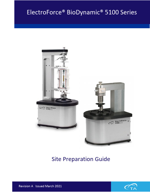
Site Preparation GuideTable of Contents (2)Ideal Setup (3)System Components (4)Instrument Measurements....................................................................................................... 5–6 BioDynamic® 5110, 5115, and 5170 – Axial Frame . (5)BioDynamic 5170 and Pulsatile Only – Pulsatile Frame (5)BioDynamic 5115 and 5175 – Torsion Frame (6)Power Supply (6)Utility Requirements ................................................................................................................ 7–8 Power (7)Miscellaneous (8)Site Preparation Checklist (9)TA Instrument Offices (10)Circulator Power Cooling Gas LN2Fluid Light Hardware Software Temp Lab CustomerIDEAL PLACEMENT AND BENCH MEASUREMENTSSelect a location with adequate floor and ceiling space and a rigid laboratory bench that is level and is in a vibration-free environment. Bench must be rated to support several hundred pounds.Distance from the wall: 0.15 m (0.5 ft) min. Table depth: 1.2 m (4 ft) Table width: 1.5 m (5 ft)MAIN SYSTEM COMPONENTSEDAA. Test Instrument – Axial Frame F. Power Supply (Axial)B. Test Instrument – Pulsatile Frame G. Emergency StopC. Computer MonitorD. Computer TowerE. PCI Electronics BoxBCGBIODYNAMIC® 5110 AND 5170 – AXIAL FRAMEBIODYNAMIC 5170 AND PULSATILE ONLY – PULSATILE FRAMEBIODYNAMIC® 5115 AND 5175 – TORSION FRAMEPOWER SUPPLYPOWERInternational: Line power cord provided is basedon countryUse power cords with plugs appropriate for your circuit.Supply voltages lower than indicated may result in a degradation of performance.Ensure that the mains assigned do not also supply power to noise generating equipment nearby, such as motors, welders, transformers, etc.An independent heavy GROUND wire must be provided through the power hookup. Improper grounding may cause severe damage for which the supplier will not accept responsibility. All power strips must be fully grounded and carry the ground through to the sockets into which the computer is plugged.6-20P 5-15MISCELLANEOUSOperatingtemperature 18°C (64°F) to 30°C (86°F) Flow Loop 18°C (64°F) to 40°C (104°F) Relativehumidity 40–65% (non-condensing)ElectroForce® BioDynamic® 5100 SeriesFor information on our latest products, contact information, and more, see our website at: .To find your local TA Instruments office and contact information, visit/contact/ta-directory/TA Instruments – Waters LLCCorporate Headquarters159 Lukens DriveNew Castle, DE 19720USATelephone: 302-427-4000Fax: 302-427-4001Email:**********************。
汉密尔顿电子混合饮料机说明书
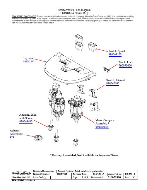
contained within it, in full or in part, for any purpose is forbidden without the prior written consent of HBB. No photographs may be taken of any article fabricated or assembled from this document without the prior written consent of HBB.4421 Waterfront Drive Glen Allen, VA 23060 Revision Description: Correct Agitator, Solid with Screw part number.Request Number: DOC7818 Revision Date: 05/17/2017 Approved by: DOC7818 Issue Code(s): Page: 1 of 3Document #: 510022800 Rev: C*Factory Assembled, Not Available As Separate Piecescontained within it, in full or in part, for any purpose is forbidden without the prior written consent of HBB. No photographs may be taken of any article fabricated or assembled from this document without the prior written consent of HBB.4421 Waterfront Drive Glen Allen, VA 23060 Revision Description: Correct Agitator, Solid with Screw part number.Request Number: DOC7818 Revision Date: 05/17/2017 Approved by: DOC7818 Issue Code(s): Page: 2 of 3Document #: 510022800 Rev: C990073800990042900990073900contained within it, in full or in part, for any purpose is forbidden without the prior written consent of HBB. No photographs may be taken of any article fabricated or assembled from this document without the prior written consent of HBB.4421 Waterfront Drive Glen Allen, VA 23060 Revision Description:Correct Agitator, Solid with Screw part number.Request Number: DOC7818 Revision Date: 05/17/2017 Approved by: DOC7818 Issue Code(s): Page: 3 of 3Document #: 510022800 Rev: CRFI Board 990050500。
卡西欧5110说明书英文版

MO1408-EA©2014 CASIO COMPUTER CO., LTD.Getting AcquaintedCongratulations upon your selection of this CASIO watch. To get the most out of your purchase, be sure to read this manual carefully.Keep the watch exposed to bright lightThe electricity generated by the solar panel of the watch iscantly E-1Radio-controlled Atomic TimekeepingThis watch receives a time calibration signal and updates its time sett ing accordingly.• This watch is designed to pick up the time calibration si gnals transmitted in Germany (Mainfl ingen), England (Anthorn), the Unite d States (Fort Collins), China (Shangqiu), and Japan (Fukushima, Fukuoka /Saga).• See the information under “Signal Reception Troubleshooting” (page E-27) if you experience problems with time calibration signal reception.• When using the watch outside the areas covered by the time signal transmitters, you will have to adjust the current time setting manually a s required. See “To set the time and date manually” (page E-58) for mor e information about manual time settings.• The U.S. time calibration signal can be picked up by the watch whil e in NorthAmerica. The term “North America” in this manual refers to the area that consists of Canada, the continental United States, and Mexico.• Using this watch in a country covered by a time calibration signal t hat is different from the countries it supports may result in incorrect time indication due to local application of summer time, etc.Current Time SettingThis watch adjusts its time setting automatically in accordance with a time calibration signal. You also can perform a manual procedure to set the time and date, when necessary.rst thing you should do after purchasing this watch is to specify your • The fiHome City (the city where you normally will use the watch). For mor e information, see “To specify your Home City” on page E-12.E-10E-11• Signal reception may not be possible at the distances that are furth er than those noted below during certain times of the year or day. Radio interference also may cause problems with reception.Mainfl ingen (Germa ny) or Anthorn (England) transmitters: 500 kilometers (310 miles) Fort Collins (United States) transmitter: 600 miles (1,000 kilometers) Fukushima or Fukuoka/Saga (Japan) transmitters: 500 kilometers (310 miles)Shangqiu (China) transmitter: 500 kilometers (310 miles) • Even when the watch is within the reception range of the transmitt er, signal reception will be impossible if the signal is blocked by mountai ns or other geological formations between the watch and signal source.• Signal reception is affected by weather, atmospheric conditions, and seasonal changes.• As of December 2013, China does not use Daylight Saving Time (D ST). If China does go to the Daylight Saving Time system in the future, some functions of this watch may no longer operate correctly.About Auto ReceiveThe watch receives the time calibration signal automatically up to six times a day (fi ve times for the Chinese calibration signal). When any au to receive is successful, remaining auto receive operations are not perfor med. The reception schedule (calibration times) depends on your currentl y selected Home City, and whether standard time or Daylight Saving Tim e is selected for your Home City.1LONStandard Time1:00 amLISDaylight Saving Time2:00 amPARStandar d Time2:00 amBERDaylight Saving Time3:00 amMADROMSTOATHStandard Time3:00 amDaylight Saving Time4:00 amMOWStandard Time4:00 amDaylight Saving Time5:00 amYour Home CityAuto Receive Start Times23452:00 am3:00 am4:00 am5:00 am3:00 a m4:00 am5:00 amMidnight*3:00 am4:00 am5:00 amMidnight*4:00 am5:0 0 amMidnight*1:00 am*6Midnight*1:00 am*1:00 am*2:00 am*4:00 am5:00 am5:00 amMidnight*5:00 amMidnight*Midnight*1:00 am* Midnight*1:00 am*1:00 am*2:00 am*1:00 am*2:00 am*2:00 am*3:00 am *E-202:00 am*3:00 am*3:00 am*4:00 am*E-21ProblemThe time setting is incorrectfollowingsignalreception. Probable CauseWhat you should doWorld TimeCurrently selected• If the time is one hour off, the DST • Change the DST setting to Auto DST setting may be incorrect.(page E-63).• The Home City code setting is not • Select the correct Home City c ode correct for the area where you are (page E-12).using the watch.• En ter the home position adjustment • The home positions of the hands are mode and adjust the home off.positions (page E-64).• For further information, see “Important!” (page E-15) and “Radio-co ntrolled AtomicTimekeeping Precautions” (page E-69).World Time CityWorld Time digitally displays the current time in one of 48 cities (29 time zones) around the world. A simple operation swaps your Home City with the currently selected World Time City.• When you enter the World Time Mode, the current month and day of the World Time City appear fi rst. After about one second, the curre nt time appears.• The times kept in t he World Time Mode are synchroniz ed with the time being kept in theTimekeeping Mode. If you feel that there is an error in any World Ti me Mode time, check to make sure you have the correct city selected as your Home City. Also check to make sure that the current time as show n in the Timekeeping Mode is correct.• Times in the World Time Mode are based on UTC offsets. See the “City Code Table” at the back of this manual for information about the U TC offsets that are supported.• All of the operations in thi s section are performed in the World Tim e Mode, which you enter by pressing C (page E-9).To view the current time in another time zoneIn the World Time Mode, use D to scroll through available city codes (time zones). Holding down the button scrolls at high speed.• When the city code (time zone) you want is selected, you can pres s A to display the date. After about one second, the watch will resume r egular timekeeping.E-30E-31To confi gure countdown start time and auto-repeat settings1. While the countdown start time is on the display in the Countdow n Timer Mode, hold down A for about three seconds until the minute set ting of the countdown start time starts to fl ash. This is th e setting mod e.• If the countdown start time is not displayed, use the procedure un der “To use the countdown timer” (page E-37) to display it.2. Press C to move the fl ashing in the sequence shown below, and select the setting you want to change.4. Press A to exit the setting mode.• The auto-repeat on indicator () will appear in the upper display whi le this function is turned on.• Frequent use of auto-repeat and the alarm can run down battery p ower.3. Perform the following operations, depending on which setting curre ntly is selected on the display.• While the start time setting is fl ashing, use D (+) and B (–) to ch ange it.• While the auto-repeat on/off setting () is fl ashing on the displa y, press D to toggle auto-repeat on ().AlarmsTo set an alarm timeWhen an alarm is turned on, the alarm tone will sound when its alar m time is reached. One of the alarms is a snooze alarm, while the other four are one-time alarms.You also can turn on an Hourly Time Signal th at causes the watch to beep twice every hour on the hour.• There are five alarm screens numbered AL1,AL2,AL3 and AL4 for the one-time alar m, and a snooze alarm screen indicated by SNZ. The Hourly Time Signal screen is indicated by SIG.• All of the operations in this section are performed in the Alarm Mo de, which you enter by pressing C(page E-9).1. In the Alarm Mode, use D to scroll through the alarm screens unti l the one whose time you want to set isdisplayed.•AL1,AL2,AL3 or AL4. To set the snooze alarm, display the SNZ scree n.•SIG is the hourly time signal setting (page E-44).• The snooze alar m repeats every fi ve minutes.2. After you select an alarm, hold down A for about three seconds u ntil the hoursetting of the alarm time starts to fl ash. This is the setting mode.• This operation turns on the alarm automatically.3. Press C to move the flashing between the hour and minute settings.(Hour : Minutes) E-40E-41 Warning!• Alwa ys make sure you are in a safe place whenever you are readin g the display of the watch using the auto light switch. Be especially care ful when running or engaged in any other activity that can result in acci dent or injury. Also take care that sudden illumination by the auto light s witch does not startle or distract others around you.• When you are wearing the watch, make sure that its auto light swi tch is turned off before riding a bicycle or operating a motorcycle or any other motorvehicle. Sudden and unintended operation of the auto light switch can create a distraction, which can result in a traffi c accident and serious p ersonal injury.To turn the auto light switch on and offIn the Timekeeping Mode, hold down B for about three seconds to t oggle the auto light switch on (auto light switch on indicator displayed) a nd off (auto light switch on indicator not displayed).• The auto light switch on indicator is on the display in all modes wh ile the auto light switch is turned on.Power SupplyThis watch is equipped with a solar panel and a special rechargeable battery (secondary battery) that is charged by the electrical power produ ced by the solar panel. The illustration shown below shows how you sho uld position the watch for charging.Example:pointing at a light source.• The illustration shows how to position a watch with a resin band.• Note that charging effi ciency drops when any part of the solar panel is blocked by clothing, etc.• You should try to keep the watch outside of your sleeve as much as possibl e. Charging is reduced signifi cantly if the face is even only par tially covered.Important!• Storing the watch for long periods in an area where there is no lig ht or wearing it in such a way that it is blocked from exposure to light can cause rechargeable battery power to run down. Be sure that the wat ch is exposed to bright light whenever possible.• This watch uses a special rechargeable battery to store power prod uced by the solar panel, so regular battery replacement is not required. However, after very long use, the rechargeable battery may lose its abilit y to achieve a full charge. If you experience problems getting the special rechargeable battery to charge fully, contact your dealer or CASIO distri butor about having it replaced.• Never try to remove or replace the watch’s special battery yourself. Use of the wrong type of battery can damage the watch.• The current time and all other settings return to their initial factory defaults whenever battery power drops to Level 5 (CHG) (page E-51) an d when you have the battery replaced.• Turn on the watch’s Power Saving function (page E-68) and keep it in an areanormally exposed to bright light when storing it for long periods. This helps to keep the rechargeable battery from going dead.E-50Battery Power Indicator and Power Recovery Mode indicatorThe battery power indicator indicates you the current status of the re chargeable battery’s power.indicatorRead This Before You Set the Time and Date!This watch is preset with a number of city codes, each of which repr esents the time zone where that city is located. When setting the time, i t is important that you fi rst select the correct city code for your Home City (the city where you normally use the watch). If your location is not included in the preset city codes, select the preset city code that is in th e same time zone as your location.•Note that all of the times for the World Time City codes (page E-29) are displayed in accordance with the time and date settings you confi g ure for the Timekeeping Mode.To set the time and date manually1. In the Timekeeping Mode, hold down A for about fi ve seconds, u ntil the watch beeps twice and the city code fl ashes on the upper displa y. This is the setting mode.2. Use D and B to select the city code you want.• Make sure you select your Home City code before changing any ot her setting.• For full information on city codes, see the “City Code Table” at the back of this manual.3. Press C to change the fl ashing screen content in the se quence sh own below to select the other settings.4. When the timekeeping setting you want to change is fl ashing, use D or B to change it as described below.E-59• The day of the week is displayed automatically in accordance with t he date (year,month, and day) settings.12-hour and 24-hour timekeeping• With the 12-hour format, the PM indicator appears to the left of th e hour digits for times in the range of noon to 11:59 p.m. and no indica tor appears for times in the range of midnight to 11:59 a.m.• With the 24-hour format, times are displayed in the range of 0:00 to 23:59, without any indicator.• The 12-hour/24-hour timekeeping format you select in the Timekeep ing Mode is applied in all other modes.5. Press A to exit the setting mode.• For details about the Daylight Saving Time setting, see “To change the Daylight Saving Time (summer time) setting” (page E-63). For inform ation about Power Saving, see “To turn Power Saving on and off” (page E-68).• Auto DST (AUTO) can be selected only while LIS,LON,MAD,PAR,RO M,BER,STO,ATH,MOW,TPE,SEL,TYO,HNL,ANC,YVR,LAX,YEA,DEN,MEX,CHI,MI A,YTO,NYC,YHZ, or YYT is selected as the Home City code. For more inf ormation, see “Daylight Saving Time (DST)” below.E-60E-61To turn Power Saving on and off1. In the Timekeeping Mode, hold down A for about fi ve seconds, u ntil the watch beeps twice and the city code fl ashes on the upper displa y. This is the setting mode.2. Press C nine times until PS appears in the upper display and a fl ashing appears in the lower display. This is the Power Saving on/off scre en.3.PressD to toggle Power Saving on (4. Press A to exit the setting mo de.Radio-controlled Atomic Timekeeping Precautions• Strong electrostatic charge can cause the time setting to be thrown off.• The time calibration signal bounces off the ionosphere. Because of t his, such factors as changes in the refl ectivity of the ionosphere, as well as movement of the ionosphere to higher altitudes due to seasonal atm ospheric changes or the time of day may change the reception range of the signal and make reception temporarily impossible.• Even if the time calibration signal is received properly, certain condi tions can cause the time setting to be off by up to one second.• The current time setting in accordance w ith the time calibration sig nal takes priority over any time settings you make manually.• The watch is designed to update the date and day of the week aut omatically for the period January 1, 2000 to December 31, 2099. Setting of the date by the time calibration signal cannot be performed starting f rom January 1, 2100.• This watch can receive signals that differentiate between leap years and non-leap years.• Though this watch is designed to receive both time data (hour, min utes, seconds) and date data (year, month, day), certain signal conditions can limit reception to time data only.E-69).E-68• If you are in an area where proper time calibration signal reception is impossible, the watch keeps the time with the precision noted in “Spe cifi cations”.• If you have problems with proper time calibration signal reception o r if the time setting is wrong after signal reception, check your current ci ty code, and DST (Daylight Saving Time) settings (page E-58).• The Home City setting reverts to the initial default of TYO (Tokyo) whenever the battery power drops to Level 5 (CHG) or when you have t he rechargeable battery replaced. If this happens, change the Home City to the setting you want (page E-12).TransmittersThe time calibration signal received by this watch depends on the cur rentlyselected Home City (page E-12).• When a U.S. time zone is selected,the watch receives the time cali bration signal transmitted from the United States (Fort Collins).• When a Japanese time zone is selected, the watch receives the tim e calibration signals transmitted from Japan (Fukushima and Fukuoka/Sag a).• When a Europe an time zone is selected, the watch receives the tim e calibration signals transmitted from Germany (Mainfl ingen) and England (Anthorn).E-70• When a China time zone is selected, the watch receives the time c alibration signaltransmitted from China (Shangqiu City).• When your Home City is LIS,LON,MAD,PAR,ROM,BER,STO,ATH,MOW (which can receive both the Anthorn and Mainfl ingen signals), the watc h fi rst tries to pick up the signal it last received successfully. If that fail s, it tries the other signal. For th e fi rst receive after you select your Ho me City, the watch tries the nearest signal fi rst (Anthorn for LIS,LON, M ainfl ingen for MAD,PAR,ROM,BER,STO,ATH, and MOW).Auto Return Features• If you leave the watch with a fl ashing setting on the display for t wo or three minutes without performing any operation, the watch will exi t the setting mode automatically.• The watch will return to the Timekeepi ng Mode automatically if you do not perform any operation for two or th ree minutes in the Alarm Mode.High-Speed Movement• The D and B buttons are used to change the hand setting in vario us settingmodes. In most cases, holding down these buttons will start high-spe ed movement of the applicable hand(s).E-71City Code TableCodePPGHNLDENMEXL-2CityPago PagoHonoluluDenverMexico CityGMT Differential–11–10–8–7–6–5CityCodeGMT DifferentialSCLSantiago–4YHZHalifaxLISLisbon0LONLondon+1STOStockholmCodeATHCAIDXBKBLCityAthensCairoDubaiKabulGMT Differential+2+3+4+4.5CodeBKKSINTYOADLCityBangkokSingaporeTokyoAdelaideGM T Differential+7+8+9+9.5+10L-3* The above is current as of December 2013. This watch does not re flect the change in the Moscow (MOW) time offset to +4. Because of th is, you should leave thesummer time setting turned on (which advances the time by one hou r) for Moscow (MOW).•This table shows the c ity codes of this watch.•The rules governing global times (UTC offset and GMT differential) a nd summer time are determined by each individual country.。
诺诺医疗血压计BP5100用户手册说明书

4 Take a measurement
1 Press the [START/STOP]
button.
2 Remain still until the arm cuff deflates.
3 After the measurement,
The bottom edge of the arm cuff should be 0.5 inch above the insidedge
3 Wrap the cuff securely.
Make sure that air tube is on the inside of your arm.
2 Insert 4 “AA” batteries.
Battery cover
3 Close the battery cover.
2 Apply the arm cuff
1 Plug the arm cuff into
the monitor.
2 Place your hand through
the cuff loop, then pull the cuff until it reaches your upper left arm.
TIP
For accurate readings: - Avoid bathing, drinking alcohol or caffeine, smoking, exercising and
eating for 30 minutes before taking a measurement. - Rest for at least 5 minutes before taking a measurement. - Sit quietly with your legs uncrossed and your feet flat on the floor.
爱德克斯IT5100用户手册

IEC 61010-1:2010/ EN 61010-1:2010
版权所有 © 艾德克斯电子有限公司
iv
IT5100 用户手册
目录
认证与质量保证................................................................................................................................................... 1 保固服务 .............................................................................................................................................................. 1 保证限制 .............................................................................................................................................................. 1 安全标志 .............................................................................................................................................................. 1 安全注意事项 ...................................................................................................................................................... 2 环境条件 .............................................................................................................................................................. 2 法规标记 .............................................................................................................................................................. 3 废弃电子电器设备指令(WEEE).................................................................................................................... 3 COMPLIANCE INFORMATION .................................................................................................................................. 4
- 1、下载文档前请自行甄别文档内容的完整性,平台不提供额外的编辑、内容补充、找答案等附加服务。
- 2、"仅部分预览"的文档,不可在线预览部分如存在完整性等问题,可反馈申请退款(可完整预览的文档不适用该条件!)。
- 3、如文档侵犯您的权益,请联系客服反馈,我们会尽快为您处理(人工客服工作时间:9:00-18:30)。
安全提示:⏹安装或操作之前请详细阅读操作手册。
(在没有完全明白型号5100的特征和功能之前而进行操作,可能会造成不安全。
)⏹气体加压时,使用保护眼罩和遵守安全的程序。
⏹确保进入的气体气压为1—3PSIG。
⏹测量气体要在相同压力和流动速度下校准。
⏹不要进行零点校正。
⏹接近传感器之前,必须待传感器冷却后。
⏹使用期期满,氧气传感器可适当处理。
⏹确保在使用之前已经校准仪器。
⏹不要靠近水或湿度大的地方。
⏹不要置于高温环境。
⏹不要直接输入不规则的气体、高压气体以防氧气管爆裂。
⏹确保分析仪的操作温度,不要置于高温的表面,不要阻塞通风口。
⏹不要置于易燃物质旁。
图表 1 MODEL 5100 说明产品保证书自购买NEUTRONICS产品即日起,产品在正常使用情况下发生故障时,能得到一年的保修服务,但由于人为不当操作所引起的损坏,不属于此保修范围。
当产品已逾保修年限发生故障时,如本公司尚有配件,则给予维修服务,但需酌收一定费用。
第一部分工作原理1.1概括Ntron 公司的5100系列分析仪,它提供了在微小氧气测量和控制运用中的有效解决。
它是为精确测量百分比范围氧而设计的一个以微处理器为基础的仪器。
分析仪的主体是微型氧化锆传感器。
氧化锆传感器是鉴定测量的固态装置,它确保可靠性和反应性。
另外一个优势是由于它是固态装置,因此不受干燥环境影响;贮存在寒冷的温度下(或断电的冷环境情况),也不会有所损坏。
1.2 特征Model5100是为嵌板或控制台而设计的装置。
因为5100分析仪体积较小,可以与各种设备或控制面板合而为一。
(图3)d其它特征包括:⏹自动量程或固定量程。
⏹RS-232 通讯接口,联结到个人电脑、电路接头和打印机。
⏹两个输出:4-20MA 和0-1,0-5 或 0-10VDC。
⏹两个报警继电器输出,可设为上下限报警。
1.3系统组成5100分析仪的主要组成部如下:(图4)1.3.1 主板5100氧气分析仪是以微处理器为基础的控制面板。
主板接收传感器信号,信号放大,处理并可提供控制和显示的功能。
1.3.2 继电器板继电器板为报警1、2和故障报警提供了干触点。
可以调整报警1、2的氧气浓度设定点。
1.3.3 电源110V AC 或220V AC 50/60 HZ直流电电压通入5100分析仪时,可以选择10—30VDC 的电源供应。
1.3.4 显示板显示板是一个氧气浓度的数据指示。
显示也会指出错误的编码。
1.3.5 控制面板控制面板为主要的用户界面。
控制面板按键区(和LED 状态的控制面板的设计是防水的。
在面板的四个角落是#8-32双头螺安置,这允许安装在控制设备或者嵌板装备上。
1.3.6 传感器CERAMA TEC ZR-200的微型氧化锆分析仪对于测量百分含量氧气是一个多方面应用的有效的解决。
它是一个在氧化锆低电源电解质的固态设置。
不象其他固态氧化锆氧气分析仪,ZR-200在正常操作下不需要参考气体。
传感器操作电路图如下:(图5)氧气传感器是一种测量氧气的电化学传感器。
它直接安装在线路板上(图6)线路控制传感器激发电压和加热器电压。
操作温度,氧气是在负极电化学减少的。
在样气里的氧气浓度是由当前通过传感器电路接头S+和S-来决定的。
传感器的应用量程设计有效地确保精度的测量和反应的灵敏。
ZR-200的主要优势是不受位置的影响。
此外,传感器能在不同的环境里使用,在正常操作环境下,使用寿命为5年!1.3.7 单元组和单元组帽该装配用作传感器的容器和样气进入分析仪传输系统。
通过传感器的限流器,样气直接从接口(1/8" NPT 内螺纹)流入,这时候,传感器就会测试流入样气的浓度。
然后,样气会通过传感器流到样气输出口(1/8" NPT内螺纹)。
传感器控制面板作为主要的装置,保留传感器,它主要是通过6个螺丝钉与单元组紧紧连在一起的。
1.3.8 底板底板是用一种特别的镀层钢板制造的。
它的设计是为了抵抗来自地方性的环境造成机械损伤的一般水平的保护。
同时,它也是ESD屏蔽设计的一个重要组成部分。
系统结构(图7)ID 主要电源输入第二部分5100 分析仪操作2.1安装2.1.1 第一步分析仪的安装位置型号5100是为安装在设备表面或在控制面板机设计的。
要为它选择一个适当的位置:⏹ 便于阅读数据和显示LED 状态 ⏹ 容易进入到显示板按钮界面。
⏹ 在底板里有充足的地方安装电气连线⏹ 分析仪不要置于水面,不利的温度或震动。
确保分析仪在空气流通的区域里安装以防止底板超过操作温度规格,不要在高温的地方安装分析仪或者传感器,不要阻塞分析仪底板的通风窗。
分析仪底板的安装要四个间隙孔,以便安装#8-32的柱头螺栓。
控制板上冲出的孔是为了可让底盘能相对于面板直接滑动。
确保在分析仪显示板的垫圈没有磨锥或者尖锐边缘在剪切块或者孔口,否则它会影响分析仪控制面板的垫圈。
控制板周围的垫圈要具有不漏水和密封的特性。
显示器本身等级类型4,防水材料。
2.1.2 第二步 分析仪的安装警告:5100氧气分析仪是一个热的微型-氧化锆氧化物的传感器。
进入传感器或控制面板之前,要使探头有足够的时间冷却,大约5分钟。
危险:5100氧气分析仪的后面连接电力时一旦电源通过元件可能有一定电压危险。
电源进入分析仪后,高电压仍然会在元件持续一段短时间。
所以,在通电时,请小心!警告:不要安装分析仪或传感器在可能接触到水或有液体元素的地方,不要让易燃物和危险物靠近分析仪。
2.1.2.1 管路安装5100氧气分析仪管路的连接在底座的传感器单元组里。
远传的传感器的连接是通过探头的样气选择的。
样气接口为1/8" NPT 内螺纹。
配件是由DELRIN 铝质材料制造的。
配件安装不能过紧,否则别的线会因此而脱落。
用于安装的细线要用1/4英寸的密封带包住以防止气体泄露。
在气体输入和输出中,建议使用1/4或1/8英寸的管。
为了更好的效果,样气气压为1—3PSIG在1SLPM 流程速度。
超过3PSIG(等于20KPA)的大气不能进入样气接口。
为了防止气压回流,样气的排放要与大气压处相通。
2.1.2.2 电气连接为了安装和维护的方便,接线盒排列的图粘在底板上面。
请参考相关的附图,它详细地说明电力的安装和取样出口。
警告:安装分析仪时,确保所有的电源已关。
不要把线头外露。
后备电源:12伏直流电压在TB3提供电路接头。
12VDC 电源固定连结在终端,以便主要电源V AC断开,也能继续运作。
为检测氧气浓度的当前范围,型号5100分析仪的特征0-10伏自动量程输出。
请看下面的电压量程输入:主电源输入在TB1接线盒(在后面的上面)。
报警和量程ID是在接线盒TB2可以使用的(在后面的中间)。
电池后备和量程输出在TB3可以使用的(在后面的底部)。
2.2 开始2.2.1 通电前检查⏹分析仪和传感器的安装地方是否已没有可燃物质⏹分析仪和传感器的安装地方是否远离常出现下雨、滴水的地方。
⏹所有的线路是否正确⏹确保气体的稳定性⏹样气排气孔的安装是否连结⏹样气气压是否适合⏹操作手册是否完全读完如果是,请开始通电。
2.2.2 第三步通电当打开相关设备电源时,5100分析仪自动进入检测模式,显示数据为“8888”,十进制。
LEDs会闪烁,大约8秒,分析仪会显示软版本号和附于设备预热。
预热时间需要210秒。
在没有读数时数据显示交替“NR”和指出预热完成之前会保持几秒。
预热之后,5100分析仪将会检测当前读数、更新数据显示和LEDS状态。
预热后可马上使用,但最好还是3分钟后再用。
这是允许传感器稳定和调整到周围的环境一旦分析仪已经稳定(3分钟)。
使用1—3PSIG样气到样气口进入分析仪。
允许阅读到稳定(大约90秒对于气体清除出去在氧气线内)后,可进入校准单元。
2.2.3 第四步校准在房间中的空气进入分析仪内后,按:“MODE”键,按下时,显示“CAL”,绿灯(RUN LED)会闪烁;放开按钮,则显示出该氧气的浓度。
按上下键来调整数据显示,使它的氧气显示为20.9%。
然后再按“MODE”,设置报警器1和报警器2。
看第三部分的量程设置。
注:当上下键或MODE键没有在120秒内按着停止的话,那么MODEL5100会重新开始到RUN的状态。
图11 CAL MODE:请看显示板注意:显示面是一个超大的LEDs,有两种显示形式:当分析仪超出正常测量范围时,显示会由明亮闪烁转为暗淡;当分析仪在测量范围内时,显示固定。
例如:如果5100分析仪固定量程为0—10%,超出此范围时,闪烁;低于时,则固定。
这说明,测量氧气只能在0—10%范围内。
如果在120秒内,没有按“UP、DOWN或MODE”,则分析仪会回到正常运行操作形式。
2.2.4 第五步报警设置分析仪校验完成后,就可以设置报警系统了。
按“MODE”,直到出现“ALM1”为止,然后调整上下键设置,再按“MODE”键设置“ALM2”。
看第三部分的报警设置大约120秒会启动警系统2.2.5 第六步返回运行形式报警系统设置完毕后,按“MODE”键进入“FAULT”状态,返回RUN运行模式。
大约120秒的时间,如果没有按任何键时,会返回“RUN MODEL”运行模式。
第三部分操作形式分析仪校验完成后,分析仪就可以进入正常动作。
通电后,通过自检或预热的有6种形式:运行,校验,报警设置,报警激活,故障和自测。
图13,在RUN状态的操作模式,按MODE开关,你会进入CAL 或SET ALARM 状态。
CAL 和ALARM1,ALARM2是连续使用。
分析仪会自动选择是否启动报警系统。
如果在2分钟内没有按任何键,5100分析仪就会自动返回RUN形式。
报警输出是“FROZEN”在校验和报警设置时。
报警条件优先进入CAL/SET ALARM 形式,然后返回到RUN形式。
报警输入在校正、报警设置的过程中是被“冻结”的,直到返回到RUN的模式时,报警情况才会优先进入CAL/ 设置报警模式在所有固定量程里,如果测量浓度超出选择量程或显示能力,仪器会显示百分含量氧,显示会闪烁,模拟输出不会再增加。
3.1运行正常RUN形式会显示绿色LEDs,仪表是测量样气浓度和输出显示。
注意:超出测量量程时,显示闪烁(由亮到暗),在范围内时,显示固定。
3.2 校验校验之前后将已知浓度的样气通入分析仪,然后按MODE 进入CAL 状态。
需要校验的情况:⏹更换传感器板时⏹一个月至少有一次⏹遇到FAULT 的时候⏹通电后(在恒温下等3-5分钟)⏹不确定氧气浓度准确时当空气进入分析仪后,按“MODE ”键,会显示“CAL ”绿灯“RUN LED ”会闪烁,释放该键时,它会出现氧气的浓度;通过按上下键使显示为20.9%,如图示再按”MODE ”进入报警设置。
注意:在120秒内,没有按“UP ”,“DOWN ”,或“MODE ”,则5100分析仪返回RUN 形式。