发 电 机[指南]
[指南]电机通风散热计算简介
![[指南]电机通风散热计算简介](https://img.taocdn.com/s3/m/b3da5f39443610661ed9ad51f01dc281e43a565e.png)
电机通风散热计算简介一、电机通风散热计算目的和意义电机通风散热计算是电机设计的主要内容之一。
电机温升直接影响绕组绝缘寿命,从而关系到电机的运行寿命和可靠性。
现代电机设计多采用较高的电磁负荷,导致电机运行时的温升明显增大,因此,电机热分析显得尤为重要。
电机的热源来源于它自身的损耗,包括铁芯损耗,绕组损耗,机械损耗。
铁芯损耗包括铁芯中主要磁场变化时产生的铁芯损耗,这种损耗一般称为基本损耗。
包括定转子开槽引起气隙磁导谐波磁场在对方铁芯中引起的损耗,以及电机带负载后,由于存在漏磁场和谐波磁场而产生的损耗。
前者称为空载附加损耗,后者称为负载附加损耗。
绕组损耗包括电流在绕组中产生的损耗,这种损耗为基本铜耗。
包括电刷与集电环或换向器接触而产生的损耗,以及工作电流产生的漏磁场和谐波磁场在绕组中产生的损耗,前者称为接触损耗,后者称为绕组附加铜耗。
机械损耗包括轴承波擦损耗,电刷摩擦损耗,转子旋转时引起转自表面与气体间的摩擦损耗以及电机同轴的风扇所需的功率。
一般小型电机损耗所占比重:定子铜耗>转子铜耗>铁耗>机械损耗。
电机本身是一个热源的传导体,其热量传递过程主要是热传导和对流换热过程,即导热和对流的综合过程。
由传热的基础知识可知,上述过程与介质的导热系数和表面传热系数直接有关。
导热系数适当温度梯度为1时,单位时间内通过单位面积的导热量。
导热系数的大小与材料的性质有关,同一材料的导热系数随温度,压力,多孔性和均匀性等因素而变化。
通常温度是决定性因素。
对于绝大多数物质而言,当材料温度尚未达到融化或气化以前,导热系数可以近似地认为是线性规律变化,即:0(1)btλλ=+。
其中λ指温度为零时的导热系数b是由试验确定的常数。
气体固体液体的导热系数彼此相差悬殊。
一般情况下金属>液体>气体>绝缘材料。
由上述内容可知大型电机本身是一个由多种材料组合而成的组合体,它的发热过程较复杂,因而它的温升过程也较复杂,但在一定的容量下,各部分的温升是一定的,温度分布也是一定的。
柴油发电机使用操作指南

使用操作指南
1、打开包装检查设备零部件及附件是否齐全。
2、请认真阅读柴油机、发电机及电瓶使用说明书,做好准备工作,按说明书要求加注柴油、机油及清洁软水。
3、紧固设备各连接螺丝及电瓶负极线,检查皮带张力,然后踩下脚轮刹车片固定设备。
4、将水泵电缆线接入发电机接线盒。
5、将空开处于断开状态,启动柴油机,调整油门使发电机输出电压保持在420V,然后固定油门。
严禁空载状态下将油门加到底或频繁调整油门。
6、在水泵管路阀门打开状态下,合上空开,启动水泵,注意观察柴油发电机组运行状况。
确保发电机输出电压不能低于350V,必要时加大油门使水泵正常运行(禁止高油门运行)。
同时观察水泵转向应和水泵标牌转向一致,否则断开空开调换电缆线任意两个线头即可。
7、柴油发电机组运行正常后,调整水泵管路阀门到水泵额定扬程后,观察机组运行状况及水泵的电压、电流及流量是否正常。
8、使用完毕,必须先断开水泵负载开关再减小柴油机油门直至停机。
注意事项:
1、使用过程中严禁高油门运行,以防损坏设备元器件。
3、每运行300小时应对设备进行一次大保养:紧固螺丝,检查三角带张力,检查油位等,具体详见柴油机、发电机及电瓶使用说明书。
2、如长时间不用需将电瓶负极断开,并保障每月充电一次。
发电机操作手册及使用指南(高级版)

发电机操作手册及使用指南(高级版)一、简介发电机是一种能将机械能转换为电能的设备,具有广泛的应用领域。
本操作手册将详细介绍发电机的使用方法和操作技巧,旨在帮助用户正确、安全地操作发电机并获得最佳的发电效果。
二、安全操作1. 环境检查在使用发电机之前,要确保工作环境干燥、通风良好,并远离易燃易爆物品。
必要时,可使用防护设备保护器具。
2. 接地保护为了防止触电事故,发电机应正确接地。
请确保发电机的接地装置完好,并保持良好的接地效果。
3. 燃油存储和加注燃油是发电机运行的重要能源,应妥善存储和加注。
加注时应避免热源和明火,并采取相应的防火防爆措施。
4. 操作人员要戴好个人防护装备在操作发电机时,操作人员要戴好适用的个人防护装备,包括护目镜、防护手套和耳塞等,以确保人身安全。
5. 定期检查维护发电机在使用一段时间后,需进行定期的检查和维护,以确保设备的正常运行。
请按照操作手册中的维护计划进行相应的检查和维护工作。
三、操作步骤1. 准备工作(1)检查发电机的燃油、冷却液和润滑油的储量,确保充足。
(2)检查机器外观和线路连接,确保无异常情况。
2. 启动发电机(1)打开发电机的电源开关,并按下启动按钮。
(2)等待发电机启动并运行稳定后,逐步加大负荷。
3. 发电机调节(1)根据需要,通过调节控制面板上的电流、电压和频率等参数,确保输出电能符合使用要求。
(2)监测发电机运行状态,如发现异常情况,及时采取相应措施。
4. 停止发电机(1)先将负荷逐渐减小,直至无负荷。
(2)关闭发电机的电源开关,并等待其停止运行。
5. 关机后的处理(1)检查发电机外观和线路连接,确保无异常情况。
(2)及时清理设备,包括清除积尘和残渣等。
(3)关闭燃油和气体阀门,确保安全。
四、常见故障排除1. 发电机无法启动(1)检查燃油是否充足。
(2)检查电池电量是否足够。
(3)检查线路连接是否正常。
2. 发电机过载保护(1)检查负荷是否过重。
(2)调整电压和频率等参数,确保在额定范围内。
发电机智能控制器操作

目录1.概述22.控制器外形结构与连线23.操作面板64.安装指南75.控制与操作说明76.测量显示数据97.警告和停机故障108.参数设置119.LCD显示和菜单系统1410.通讯功能1611.控制器启用前的准备工作2012.技术参数211 .概述:ACCESS4000X智能控制器是由一个微电脑处理器作为柴油发电机组的主要控制系统。
此控制器采用了最先进的电脑线路板,同时提供了强大而操作简单的系统,它集测量、控制、保护、四遥等众多功能于一体,完全满足发电机使用者或专业组装厂对不同类型的发电机组自动控制需求。
控制器测量显示发电机输出的所有电参数,采用真有效值测量,确保数据更准确。
中英文菜单选择,大屏幕LCD显示各测量参数和状态。
多至16组类比式或数位式故障讯号输入。
所有启动及停机执行程序、机组运作状态及故障保护状态等功能都可以显示于控制器上。
当发电机组发生了紧急的故障,发电机组会立刻停机作保护,20组故障记录,设定参数内容不会流失。
一系列的选择性配套可供客户选择,通讯协议完全公开及RS-485通讯接口,可以达到中央监控系统要求BMS或SCADA监控系统,亦可配备遥距监测状态传导器作机组状态监测。
控制器模块是使用坚固的铁壳作为外壳,安装于控制屏的屏面上。
控制器的所有连线都通过针式带锁的端子连接,令设备的连线、移动、维修、更换非常容易和方便。
2 .控制器外形结构与连线:2.1详细尺寸如下:本说明书只适用卜ACCESS4 Hill X发电机智能控制器,凡使用者必须先详阅本说明书。
操作面板W280mmH215mm安装开孔口W250mH185m厚度D65.5mm(未连线)ACCESS4000X 280X)用。
E2.2接线端口:控制器“D/C”直流接线端控制器“RS485”通讯接线端23典型接线图:i ncx-g*>p*lx¥ucm,•二”・p口X。
口222.nn D<"BJr«!o i23g>-<-8:48:ETr-一E“gw jg:3JP¥^-J Alw—IX93』夕革”§▼S8Ss SME,岑F u8G Mn?•X En y cj d?A3M«d Au?cAT-4mU4Am3操作面板整个操作面板分三部分:测量参数LCD显示、操作开关和运行状态发光二极管指示。
发电机组设计手册(全面)
精心整理一、概述1、本设计手册范围本手册适用于沃尔奔达(VeryPower )柴油发电机组的安装指南。
在设计和安装柴油发电机组之前,请仔细阅读本手册,详细了解设备情况,只有正确的安装并维护保养设备,才能够保证设备安全有效地运转。
机组运22.12.22.3((GB50055-93/JGT16-92)二、发电机组选型1、概述柴油发电机组一般分为主用和备用。
为了缓解全国用电紧张状况,一些工厂及生产企业将柴油发电机组作为主用电源,以应对电力系统停电或错峰供电等电力供应紧张时的电力需求。
在电力资源相对充足的情况下柴油发电机组一般作为备用电源。
2、机组功率选择2.1功率的定义和匹配沃尔奔达发电机组功率定义遵循ISO8528标准,柴油发电机组的输出功率受周围环境的限制,沃尔奔达发电机组标定的功率是在“标准状态”下的输出功率。
1000m小时;备80%~90%负e.机房的通风、排烟状况f.负载特性(如非线性负载,用电设备单机最大容量) 2.3功率折损当周围的环境比上述的“标准状态”更恶劣时,发电机组的功率会有一定的折损,要进行功率修正。
3、负载对机组的影响突加较大负载及大功率异步电动机的起动对发电机组影响较大,发电机组在突加负载后必须有足够的恢复频率能力。
沃尔奔达发电机组所有机型对首次突加60%额定功率已经过多次实践证实;对于首次突加负载超过60%额定功率时,请咨询沃尔奔达新能源股份有限公司技术开发中心。
5~7余量。
(1)计算容量式中:P jP∑η(2)按最大的单台电动机或成组电动机起动的需要,计算发电机组功率:P=(P∑-Pm)/η∑+PmKCcosψm(kW)式中:Pm---功率最大的电动机或成组电动机的功率(kW);η∑---总负荷的计算效率,一般取0.85;cosΨm---电动机的起动功率因数,一般取0.4;K---电动机的起动倍数;C---全压起动C=l.0,Y—△起动C=0.67,自耦变压器起动50%抽头C=0.25,65%抽头C==0.42,80%抽头C=0.64。
发电机保养指南

发电机保养指南发电机作为关键的机械设备,需要定期保养以保持良好的运行状态。
1、清洁表面及环境检查柴油发电机组外表面和机房内污渍,需清洁发电机组外表和机房内部的污渍和灰尘。
检查和清洁频率应至少每月一次,保证发电机组干净及周边环境整洁。
2、检查紧固件发电机中的紧固件包括发动机固定螺钉、传动带等。
在日常检查中,应对这些紧固件进行仔细检查,确保其没有松动或脱落现象。
发电机的皮带张力应定期调整以确保良好的传动效果。
皮带过松会导致打滑,影响动力传递;皮带过紧则会加速磨损,缩短使用寿命。
调整皮带张力时,应使用专业的张紧轮进行调整,使其保持适当的松紧度。
检查频率应至少每月一次,以保证发电机的正常运行。
3、清洁发电机清洁发电机是保养的重要环节,包括散热器、空气过滤器等部位的清洁。
散热器应定期清洗以保持良好的散热效果,避免发动机过热。
空气过滤器应定期更换,防止灰尘和杂物进入发动机,影响其正常运转。
清洁工作应至少每季度进行一次,以保证发电机的良好工作环境。
4、检查燃油机油防冻液检查柴油箱中的燃油量是否足够(燃料应足够运行8-12小时),防止因油量不足而影响发电效果。
检查燃油、润滑机油是否泄漏,定期更换三种滤清器,定期更换机油。
检查防冻液是否足够,是否泄漏,若防冻液不足或泄漏,需及时添加和修理。
5、润滑轴承与齿轮轴承和齿轮是发电机的重要组成部分,需要定期润滑以减少磨损。
润滑部位主要包括发动机轴承、传动齿轮等。
在润滑过程中,应使用适当的润滑剂,均匀涂抹在轴承和齿轮表面,确保润滑效果。
润滑工作应至少每半年进行一次,以保证发电机正常运行。
6、检查电气系统发电机的电气系统包括电池充电、电路等,需要保持完好以确保正常运行。
电池应定期检测电量,电量不足及时充电或更换,避免电量不足影响发电机的启动。
电路应保持完好,避免短路或断路现象。
电气系统的检查频率应至少每季度一次。
7.、更换磨损部件发电机中的部件会因磨损而失效,需要及时更换以避免影响正常运转。
新能源行业中的风力发电技术设备选型指南

新能源行业中的风力发电技术设备选型指南近年来,随着环保意识的提高和对可再生能源的需求增加,风力发电作为一种清洁、可持续的能源形式逐渐受到关注。
然而,在进行风力发电项目时,选择合适的技术设备成为一个关键的环节。
本文将以新能源行业中的风力发电技术设备选型为题,为您介绍相关事项并提供指南。
首先,选定适合的风力发电机型是至关重要的。
风力发电机型的选择需要考虑多个因素,包括但不限于以下几个方面:1. 风能资源评估:在选型前,需要对风能资源进行评估。
这包括风速、风向、年平均风速等指标的测量。
通过风能资源评估,可以初步确定适合该地区的风力发电机型。
2. 厂家信誉与技术实力:选择具有良好信誉和较强技术实力的厂家可以确保风力发电机型的质量和服务。
3. 机型适应性:不同地区的风能资源、气候条件、地形地貌等都不尽相同,因此选型时需要考虑机型的适应性。
选择具有较大适应性的机型,可以提高风力发电系统的性能和可靠性。
4. 效率和产能因素:机型的效率和产能是选型时需要关注的重要指标。
高效率和大产能的风力发电机型可以提高系统的能量产出,从而降低能源成本。
5. 维护和保养成本:除了初投资成本,维护和保养成本也是一个需要考虑的因素。
选择具有低维护和保养成本的风力发电机型可以降低运营成本。
其次,风力发电设备的选型还需考虑接入电网的方案。
在选择风力发电机型后,接入电网方案的选型也是一个重要环节。
以下是一些需要考虑的因素:1. 电网类型:根据当地的电网类型和电网运行情况,选择适合的接入方案。
常见的接入方案包括并网发电和离网发电两种。
2. 并网发电:对于大规模的风力发电项目,通常采用并网发电方式。
在并网发电中,需要考虑发电系统与电网的连接方式、电网的可靠性和稳定性等因素。
3. 离网发电:对于一些偏远地区或岛屿等无法接入电网的地方,采用离网发电方式。
在离网发电中,需要考虑发电系统的储能设备、负荷管理和供电可靠性等因素。
最后,风力发电设备的选型还需考虑项目的经济性及环保性。
僵毁 发电机使用指南

僵毁发电机使用指南《僵毁发电机使用指南》嘿,小伙伴们!你们有没有在玩僵毁的时候,为发电机的使用而烦恼过?反正我是有过啦!今天就让我这个“小小行家”来给你们讲讲僵毁里发电机的使用方法吧!首先,咱们得先找到发电机。
这可不是件容易的事儿,就好像在一堆乱草里找一根针一样难!你得在各种废弃的房子、仓库里到处翻找。
有时候,我找得满头大汗,心里那个着急呀,就忍不住想:“这发电机到底藏哪儿去啦?”好不容易找到了发电机,可别高兴得太早,这才只是第一步呢!接下来,咱们得给它加油。
这就好比汽车没油跑不动,发电机没油也没法工作呀!那怎么加油呢?你得先找到合适的燃油,这燃油也不是随便就能找到的,得靠咱们的火眼金睛去发现。
我有好几次,找燃油找得腿都快断了,心里直嘀咕:“这燃油难道是长翅膀飞啦?”加好油之后,就得连接电线啦。
这电线的连接可不能马虎,要是接错了,那发电机可就罢工啦!每次连接电线的时候,我都小心翼翼的,手都有点发抖,生怕出错。
我总是在心里给自己打气:“一定要接对呀,不然就前功尽弃啦!”当一切都准备就绪,按下启动按钮的那一刻,别提多紧张啦!心里就像揣了只小兔子,怦怦直跳,不停念叨着:“可一定要启动成功啊!”要是发电机顺利启动,那一瞬间,感觉自己就像拯救了世界一样开心!要是没启动成功,哎呀,那失落的心情,简直没法形容,感觉天都要塌下来啦!有一次,我和小伙伴一起玩僵毁。
我们找了好久才找到发电机,结果加油的时候发现燃油不够,那叫一个着急啊!小伙伴说:“这可咋办呀?”我咬咬牙说:“咱们再去找找,一定能找到的!”最后,我们跑了好几个地方,终于找到了足够的燃油,成功启动了发电机,那一刻,我们高兴得又蹦又跳。
还有一次,我自己一个人玩,连接电线的时候不小心接错了,发电机怎么都启动不了。
我气得直跺脚,“哎呀,怎么这么不小心!”后来,我静下心来,仔细检查,重新连接,终于让发电机工作了,那种成就感,简直爆棚!所以呀,小伙伴们,使用发电机可不容易呢!但是只要咱们细心、耐心,就一定能让它乖乖为咱们服务。
NOVA混合动力发电机手册和自我维护指南说明书
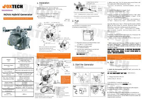
NOVA Hybrid GeneratorManual and Self-maintenance Guide V1.1Weight重量4.0kg(8.8lb)w/o Accessories/5.2kg(11.5lb)Total4kg 不含配件/5.2kg 总重量Generated Output功率1.8kW Continuous/2.0kW Max.Power1.8KW 持续功率/2KW 最大功率Dimension(L x W x H)尺寸(L x W x H )260x 312x 325mm/10x 12x 12in Applicable UAV Types适用机型Multicopters &VTOL Fix-wings多轴旋翼、垂直起降固定翼Max.Take-off Weight适用机型最大起飞重量18kg for Quadcopter 21kg for Hexacopter四轴建议18kg ,六轴建议21kgOutput Voltage适用机型动力电压12S (49V)12S (49V)Fuel Consumption油耗560g/kw ·h (hovering 1.5L/h )560g/kw ·h (悬停1.5升/小时)Service Temperature使用温度环境-20~40°C Altitude使用升限(海拔)2000m1.InstallationInstalling NOVA to UAV,default is lifted way.将NOVA 安装至无人机的合适位置,默认为吊装。
①Firstly mount the fuel tank under drone frame.首先吊装油箱总成。
②Secondly install NOVA under the tank.然后安装发电机。
Unit:mm 单位:mmDefault mounting method is in the lifted way.Other mounting methods may lead to damper failure.出厂默认为吊装,其他安装方式会导致减震器损坏。
柴油发电机的冷却系统设计指南

柴油发电机的冷却系统设计指南随着工业的快速发展,柴油发电机在各个领域得到了广泛应用。
为了保证柴油发电机的正常运行和延长其使用寿命,冷却系统的设计变得至关重要。
本文将为您介绍柴油发电机的冷却系统设计指南,以帮助您实现最佳的工作效果。
一、冷却系统的基本原理柴油发电机的冷却系统主要通过循环冷却剂来实现对发动机的散热。
冷却剂在发动机中循环流动,带走发动机产生的热量,从而保持发动机在适宜的工作温度范围内。
冷却系统由冷却剂、水泵、散热器、风扇等核心组件组成。
1. 冷却剂选择选择合适的冷却剂非常重要。
一般情况下,乙二醇是常用的冷却剂,因为它具有良好的热稳定性和抗腐蚀性。
但是,在选择冷却剂时,需要考虑到环境和运行条件,以确保其能够适应相应的工作环境。
2. 水泵的选择水泵是冷却系统的核心组件之一,负责将冷却剂循环送至散热器。
在选择水泵时,需要考虑其流量和扬程。
流量决定了冷却剂的循环速度,而扬程则决定了冷却剂能够循环到发动机的各个部分。
3. 散热器的设计散热器是冷却系统中起到关键作用的部件,它将冷却剂散热至周围环境。
散热器的设计应当合理,以充分利用空气流动和冷却剂流动的热传导特性。
通常情况下,采用铝制散热器能够提供更好的散热效果。
4. 风扇系统的设计风扇系统通常与散热器相结合,用于增加空气对散热器的流动。
当冷却系统无法通过自然对流达到预期效果时,风扇系统将发挥重要作用。
在设计风扇系统时,应考虑到所需的风量和风速,以确保散热效果的充分。
二、冷却系统的设计要点在柴油发电机的冷却系统设计中,以下几个要点需要特别注意:1. 热负荷计算在冷却系统设计之前,需要对发动机的热负荷进行准确的计算。
这包括考虑到发动机的功率输出、运行时间、环境温度以及附件的热负荷等因素。
只有准确计算了热负荷,才能保证冷却系统的设计能够满足实际需求。
2. 流动分析冷却系统中的冷却剂流动状况对发动机的冷却效果有着直接影响。
因此,在设计过程中,需要进行流动分析,以确保冷却剂能够在整个系统中的合理流动,达到最佳的冷却效果。
熊猫发电机使用指南
熊猫发电机使用指南1. 引言1.1 目的和范围本文档旨在提供关于如何正确、安全地操作和维护熊猫发电机的详细说明。
涵盖了从启动到停止,以及常见问题解决等方面。
1.2 定义与缩写词汇表- 熊猫发电机:一种便携式汽油或柴油驱动的发电设备,用于产生临时或应急用途所需的电力。
2. 准备工作在开始使用之前,请确保已经完成以下几个步骤:a) 检查所有附件是否完好无损,并按装配图示进行组装;b) 验证并添加足够量合适类型(汽油/柴油)的能源来源;c) 尽可能将其放置在平坦稳定而通风良好处;3. 启动过程步骤:a) 打开主控制台上断路器;b) 调整初始负载设置为最低值;c)打开可调节阀门, 并轻推手摇按钮直至引擎启动;4.运行中注意事项- 不要超出额定负载,以免损坏发电机;- 定期检查油位和冷却液水平,并根据需要进行添加或更换;- 避免长时间连续运行,应给予适当的休息时间;5.故障排除以下是一些常见问题及其解决方法:a) 发动机无法启动:检查燃料供应是否正常、点火系统是否工作等。
b) 输出功率不稳定:可能是由于过高或过低的负载引起,请调整合理的负荷。
6. 停止操作步骤:a)将初始设置恢复到最小值;b)关闭可调节阀门, 并断开主控制台上断路器;7. 维护与保养- 每次使用后清洗外壳并擦拭干净;- 定期更换空气滤清器和火花塞等易耗件;8. 法律名词及注释- 熊猫发电机: 根据《国家能源局关于加强便携式汽油/柴油驱动型内燃机组产品管理有关事项通知》规定生产销售企业必须具备相应资格证书方可经营该产品。
9. 附件- 熊猫发电机组装图示。
Fischer Panda 发电机与 Victron Energy GX 设备连接指南说明书
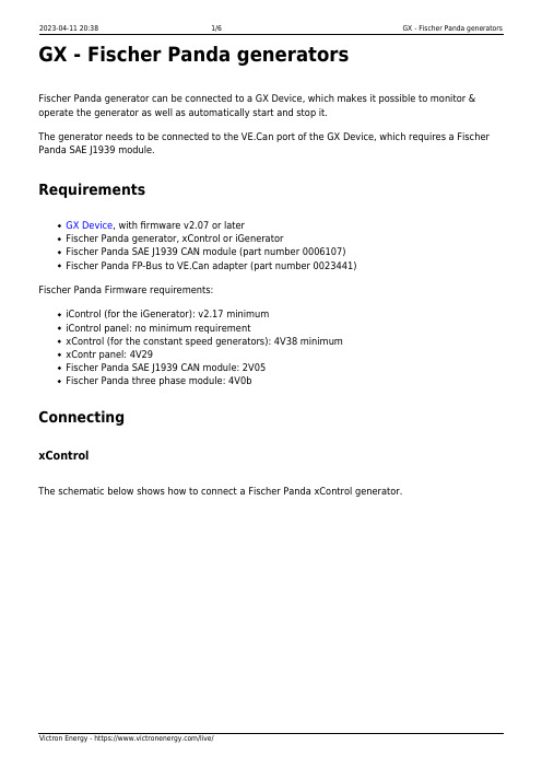
GX - Fischer Panda generatorsFischer Panda generator can be connected to a GX Device, which makes it possible to monitor & operate the generator as well as automatically start and stop it.The generator needs to be connected to the VE.Can port of the GX Device, which requires a Fischer Panda SAE J1939 module.RequirementsGX Device, with firmware v2.07 or laterFischer Panda generator, xControl or iGeneratorFischer Panda SAE J1939 CAN module (part number 0006107)Fischer Panda FP-Bus to VE.Can adapter (part number 0023441)Fischer Panda Firmware requirements:iControl (for the iGenerator): v2.17 minimumiControl panel: no minimum requirementxControl (for the constant speed generators): 4V38 minimumxContr panel: 4V29Fischer Panda SAE J1939 CAN module: 2V05Fischer Panda three phase module: 4V0bConnectingxControlThe schematic below shows how to connect a Fischer Panda xControl generator.iControlThe schematic below shows how to connect a Fischer Panda iControl generator.Important: Operation of the generator is only possible and allowed when the xControl or the iControl panel is switched on.GX DeviceIn Settings → Services, the selected canbus profile must be one that says NMEA2000. (The default). When all wiring is complete and the setup has been correctly carried-out, the Fischer Panda will show up in the device list:Entering the Fischer Panda device on the menu reveals a page like this:Notice that it features an on/off switch as well as displaying status information, and the main AC parameters: voltage, current and power.Engine temperature, RPM and additional information are all available by entering the Engine sub menu item.Generator start/stopIn addition to the manual start/stop and monitoring, there is also an automatic start/stop feature. This has the same comprehensive range of options as the Generator start/stop feature associated with the GX relay. See generator_start_stop for the manual.MaintenanceWhenever performing maintenance on the generator, be sure to stop the generator from the Fischer Panda control panel. This will disable the Fischer Panda autostart feature, and ensures that the generator cannot be remotely started - by a CCGX, for example.When the maintenance is completed, make sure you enable the autostart feature again. You can do this on the Fischer Panda control panel in the menu generator → autostart → turn on / off. MFD AppThe Marine MFD HTML5 app (more information here) also contains an element which allows monitoring as well as control of the Fischer Panda generator:TroubleshootingI've set the mode of the genset to 'On' or 'Auto start/stop' but the generator is not starting/running.Make sure the Fischer Panda autostart feature is on, this allows the GX control the remote on/off ofthe genset. You can find this option on the control panel in the menu generator → autostart →turn on / off.If you're manually trying to start the genset, a toast message appears with the text AutoStart functionality is currently disabled, enable it on the genset panel in order to start the genset from this menu.If the generator auto start/stop is enabled, it will show error #1 Remote switch controldisabled on the Auto start/stop page.。
柴油发电机组的选择与机房设计

柴油发电机组的选择与机房设计(以高层建筑/企事业/船舶为例)一、设置原则一级负荷应由两个电源共电。
二级负荷当条件允许时也宜由两个回路供电,特别是属于消防用电的二级负荷,应按二级负荷的两个回路要求供电。
由此可见,高层建筑对供电的可靠性要求较高,都要求两个电源供电。
因此,考虑设置柴油发电机组的原则如下:①对电网能够提供二个独立电源的高层建筑,按规范已经满足了一、二级负荷的要求,原则上可不设柴油发电机组。
但是,对于特别重要的高层建筑(如超高层建筑),其内部含有特别重要负荷,应考虑一电源系统检修或故障时,另一电源系统又发生故障的严重情况,此时一般应设柴油发电机组做应急电源。
②对于当地电网只能提供一路电源、或取得第二电源有困难或不经济合理的高层建筑,应设柴油发电机组提供第二电源。
此时,柴油发电机组是作为备用电源使用,不仅仅是应急用。
③按照我国旅游饭店星极标准,四星级及五星级宾馆应设自备发电系统。
以上是设置柴油发电机组的基本原则。
值得一提的是,在国内外一些高层建筑中,即使市网供电相当可靠,可以满足规范要求,但也都设置了自备应急发电机组,以便当市网万一中断供电,一方面能保证停电期间消防用电的需要,同时也能使大厦的基本秩序得以维持。
二、柴油发电机组容量的选择(船舶电站容量的选择)发电机组采购指南——容量选定一个单位在购置发电机组时,对发电机组的容量选定必须做出科学.合理选择,既不要贪图节省,选用了容量不足的机组,以致系统无法正常工作,也应该避免盲目投资,买来容量过大的机组,造成资源浪费.通常发电机组容量选定可遵循以下二条法则:(一). 统计估算法1.充分统计本单位各用电设备的功率总和P1:包括生产设备.公共设施(如电梯等).办公设备.消防设施.生活设施等;2.估算今后一段时间(如3年)内,可能会增加的各类设施的容量P2;3.分析已经存在与准备增加的设施中,超过7KW的大功率用电器的情况,评估该类设施的起动功率P3,此为机组容量确定之难点本站对此提供免费咨询服务;4.最后确定发电机容量:P= P1+P2+P3。
水电站运行安全作业指南
水电站运行安全作业指南一、设备检查与维护1、水轮机与发电机定期对水轮机和发电机进行全面检查,包括转动部件的磨损情况、轴承的润滑状态、定子和转子的绝缘性能等。
检查水轮机的叶片是否有损伤、裂纹,确保其正常运转。
同时,要注意发电机的输出电压、电流和频率是否稳定,符合规定标准。
2、调速系统调速系统是控制水轮机转速的关键部件,应定期检查调速器的灵敏度、稳定性和准确性。
检查油压装置的油压是否正常,管道是否有泄漏。
还要检查调速器的电气控制部分,确保信号传输准确无误。
3、励磁系统励磁系统对于发电机的正常运行起着重要作用。
要检查励磁调节器的工作状态,确保输出的励磁电流稳定可靠。
检查励磁变压器的温度、声音是否正常,有无过热和异常响动。
4、变压器对主变压器和厂用变压器进行定期巡检,观察油温、油位是否正常,检查变压器的高低压侧接线是否紧固,有无过热现象。
同时,要进行绝缘电阻和绕组直流电阻的测量,以判断变压器的绝缘状况。
5、开关柜与继电保护装置检查开关柜内的电气元件是否正常工作,触头有无烧蚀,接线是否松动。
继电保护装置要定期校验,确保其动作的准确性和可靠性,能够在故障发生时及时切断电路,保护设备和人员安全。
6、输电线路对水电站的输电线路进行定期巡视,检查杆塔是否倾斜,导线是否有断股、松股现象,绝缘子是否有破损、放电痕迹。
要及时清理线路通道内的树木和障碍物,确保线路的安全运行。
二、运行操作规范1、开机与停机操作开机前,要全面检查设备状态,确认无误后按照操作规程依次启动辅助设备、调速器、励磁系统,最后启动水轮机和发电机。
停机时,应先逐步减少负荷,然后按照相反的顺序进行停机操作。
在操作过程中,要密切观察设备的运行参数,如有异常应立即停机处理。
2、负荷调整根据电网的需求和水电站的实际情况,合理调整机组的负荷。
在调整负荷时,要注意缓慢平稳,避免机组出现剧烈波动。
同时,要密切关注机组的各项参数,如功率因数、电压、频率等,确保其在规定范围内。
AVK发电机结构和参数说明指南
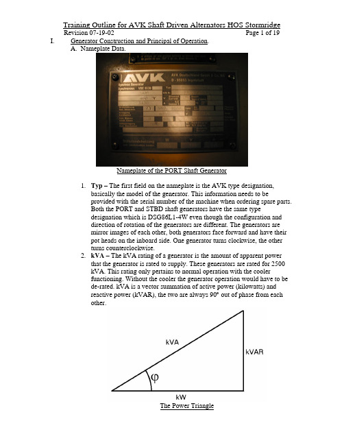
of191Page 07-19-02RevisionI.Generator Construction and Principal of Operation.plate Data.Nameplate of the PORT Shaft Generator1.Typ – The first field on the nameplate is the AVK type designation,basically the model of the generator. This information needs to beprovided with the serial number of the machine when ordering spare parts.Both the PORT and STBD shaft generators have the same typedesignation which is DSG86L1-4W even though the configuration anddirection of rotation of the generators are different. The generators aremirror images of each other, both generators face forward and have theirpot heads on the inboard side. One generator turns clockwise, the otherturns counterclockwise.2.kVA – The kVA rating of a generator is the amount of apparent powerthat the generator is rated to supply. These generators are rated for 2500kVA. This rating only pertains to normal operation with the coolerfunctioning. Without the cooler the generator operation would have to bede-rated. kVA is a vector summation of active power (kilowatts) andreactive power (kVAR), the two are always 90° out of phase from eachother.The Power TriangleThe kVA rating is used in conjunction with the Power Factor to determinerated kVAR (reactive power) and rated kW (active power). kVA can becalculated by the following formula:10003⋅⋅=I E kVA Where:E = Voltage (read from panel voltmeter)I = Apparent Current (read from panel ammeter) Note: The square root of three is incorporated for three phase AC systemsonly, it’s equates to about 1.732. Example:If you read 460 VAC on the voltmeter and 1200 Amperes on the ammeterthe kVA you are currently supplying would be:95610009560641000732.11200460≅=⋅⋅=kVA kVA kVAThe result is just shy of 1000 kVA, which is almost 1 MVA.You can use the reading off of the kW meter with the kVA calculated inthe above mentioned formula to figure out your kVAR by using the following formula:22kW kVA kVAR −= Example:Using the kVA that we calculated above and a kW meter reading of 750kW we can calculate the kVAR:593351436562500-913936)750()956(22≅==−=kVAR kVAR kVAR kVAR3. Nr. – The serial number of the generator. The PORT generator’s serialnumber is 8124498 A102, and the STBD generator’s serial number is8124498 A202.4. V – The generator rated voltage. These generators are rated for a no loadvoltage of 460 VAC. The Wye symbol after the voltage has a little lineextending vertically from the intersection which designates that theNeutral of the Wye connected stator winding is connected outside in thepot head on a bar, not in the winding head. This is advantageous for doinginsulation tests on the windings phase to phase as well as individuallyphase to ground and provides accessibility to the differential protectioncurrent transformer.5. Current – AC, Alternating Current.6. Years of manuf . – The year that the generator left the factory, 2001.7. A – The rated apparent current of the generator. Again, like apparentpower, the apparent current is a vector summation of the active (orresistive) current and reactive current. Like the sum of active and reactivepower, they are always 90° apart from each other. The active current is thekilowatt portion and is due to the purely Ohmic resistance of the load,while the reactive current is due to the inductance or capacitance of theload. These generators are rated for 3138 amperes of apparent current.8. Coolant T. – Coolant temperature, 50°C.9. p.f. – Power Factor, the ratio of active power to apparent power or theratio of kW to kVA. The power factor can be read off of the Power Factorpanel meter or it can be calculated by taking the reading of the kW panelmeter and dividing it by the result of the kVA calculation above in I.A.2.In Germany a comma is used as a period in numbers, so the 0,80 on thenameplate would read as a power factor of 0.80.Example:We can calculate the power factor of the example on page 2 by dividingthe 750 kW read from the meter by the 956 kVA that we calculated:78.0..956750..==F P kVA kW F PA power factor of 0.78 is just under 0.80, just a slight amount on thereactive side. Power factor can be either “leading” or “lagging” dependingon the load. On these shaft generators, the power factor will always belagging because of the loads they supply, and because they are never runin parallel. If the load is mostly inductive, then the power factor will be“lagging” because the phase angle of the current “lags behind” the phaseangle of the voltage. When the load is mostly capacitive, then the powerfactor will be “leading” because the phase angle of the current “leadsahead of” the phase angle of the voltage.10. Rot. Direction – The direction of rotation as viewed from thedriven/coupling end. The PORT generator is counterclockwise rotatingand the STBD generator is clockwise rotating. The direction of rotation ofthe rotor effects the phase rotation of the generator, that is why the PORTshaft generator has a W-V-U phase sequence, and the STBD shaftgenerator has a U-V-W phase sequence.11. 1/min – This field shows the phase rotation of the generator as well as the r.p.m. (revolutions per minute). See 10. above for an explanation of phasesequence. Revolutions are a unit-less quantity, so the designation 1/min isused to indicate r.p.m. These generators are designed to produce a 60Hzvoltage at 1800 rpm. The Scana gearbox has a 1:2 ratio, so that when themain engine is running at 900 rpm, and there is no slippage in the clutch,the shaft generator will be rotating at 1800 rpm.12. cps - Cycles Per Second or Hz, Hertz. The frequency of the generator atrated speed. There is a formula for motors and generators involving thenumber of poles and the rated speed for a given frequency:nf rpm 60⋅= Where:f = frequency in Hz (cycles/second)n = number of pole pairs, the number of actual poles divided by 2. Note: The 60 is there to convert the cycles per second into revolutions perminute.These generators are four pole machines, which gives us two pole pairs. In order to get 60 Hz we need to turn the shaft of the generator at:18002360026060==⋅=rpm rpm rpmThere is something interesting worth noting here, at 1800 rpm the machineis making 30 revolutions per second. The frequency of the AC we get atthis speed is 60 Hz or 60 cycles per second, that means that we get twofull cycles of AC in each phase per every one revolution of the rotor.13. Phases – The number of phases in the generator stator winding. These arethree phase generators, labeled U, V, and W. Each phase is a separatewinding, and each winding is 120° out of phase from the others. The endsof the windings are labeled so that the load side of the winding is notedwith a subscript 1 and the neutral or Wye point end is labeled with asubscript 2. The U phase ends are U 1 and U 2, the V phase ends are V 1 andV 2, and the W phase ends are W 1 and W 2. U 2, V 2, and W 2 are allconnected on the N bar in the pot head.14. Excitation – The voltage and amperage of the excitation at rated load,which is 3.6 Amperes at 40 VDC.15. Insul. Class – Insulation Classification of the windings, class H.16. Circ. Diagr. – The schematic circuit diagram number.17. Aux. Excitation – The voltage of the pilot exciter windings, 90VAC at60Hz. The pilot exciter windings are inside the same slots as the mainstator windings. The same magnetic field from the main rotor that inducesa voltage in the main stator winding induces a voltage in the pilot exciterwindings. There are two separate pilot exciter windings.18. RIS degree – The rating of the static noise interference level.19. Weight – the weight of the generator, 5.6 metric tons.20. Anti condensation heater – Rating of the anti condensation heaterinstalled under the generator stator winding at the NDE (Non-DrivenEnd). The heater is rated at 550 Watts with an applied voltage of 120VACand a current draw of 4.6 Amperes.B. Stator Winding – The stator contains a three phase alternating current windingconnected in WYE with the Neutral or WYE point connected externally in the pot head of the generator. The 460 VAC is generated in this winding by themagnetic fields from the rotor poles cutting the conductors of the winding.One Rotation of the Rotor in a Four Pole Three Phase Generator-800-600-400-20020040060080025507510012515017520022525027530032535015406590115140165190215240265290315340Electrical Degrees of Rotation (2 times the physical rotation of the Rotor)V o l t s A CHere is a simplified explanation of the three phase winding voltages in yourfour pole shaft generators:At an angle of zero degrees of the rotor to the U phase, the U phase voltage is at zero Volts, the V phase voltage is at about –560 Volts, and the W phase isat about +560 Volts. As the rotor turns its magnetic fields through the statorwindings, the voltage in the U phase increases until the magnetic flux of therotor pole is at its maximum to the U phase, this is at 45°. At 45°, the voltagein the U phase reaches its maximum and thereafter it goes back down againtowards zero volts as the pole moves away from the winding, and gets to zero at 90° of rotation of the rotor. While all of this is happening in the U phase,the V phase has gone to its maximum negative voltage, back to zero, and is on its way to the maximum positive voltage when the U phase reaches zero Volts again. Through all of this the W phase has been decreasing from +560 Volts,gone through zero and worked its way to its maximum negative voltage and is on its way back to zero.From 90° on to 135° of rotor rotation, the other pole begins to approach the U phase, remember that if one pole is a “north” then the pole next to it will be a“south.” The flux lines move in the opposite direction causing the inducedvoltage in the winding to change direction, so now the voltage induced in theU phase reverses and becomes negative. The voltage in the U phase continues to become more and more negative until that pole is directly within thewinding with the most flux lines crossing the winding, and that is when themaximum negative voltage is induced in the U phase. From 135° to 180° thepole moves away from the maximum point and the voltage induced in the U phase becomes less and less negative until it reaches zero volts again. After 180° the whole cycle repeats itself since the next pole approaching will be the same as the first pole at 0°. Since there are two pole pairs on the rotor you get two full sine waves of AC for every revolution of the rotor.C.Rotor Poles – There are four salient poles in the rotor. The poles are securedby wedge clamps inserted in between the poles.View into NDE of Main Stator and RotorThe poles create the magnetic field which is rotated within the stator core and winding to create the three phase AC voltage. Each of the salient poles is a large electromagnet alternately wound as a North, South, North, South.Main Rotor Poles from a partially disassembled AVK generator of a similarconstruction as the shaft generatorsThe DC current supplying the poles of the rotor comes from the rotatingrectifier via the wires labeled J and K which run through the center of theshaft. All four poles are connected together in series, so in other words, the same current flows through all four poles.D.Pilot Exciter Winding in Stator – There are two separate single phase ACwindings inserted into the stator slots which comprise the pilot exciter. The pilot exciter winding connections are labeled UH1 – UH2 and WH1 – WH2.Just as in the main winding, an AC voltage is generated in the pilot exciter winding from the cutting of the windings by the magnetic fields of the rotor poles. When the generator is first exciting itself, this is where things first start to happen. Before the rotor poles are excited by the DC current from therotating rectifier, they normally have a certain amount of residual magnetism from being magnetized before. This residual magnetism begins inducing a voltage in the pilot exciter winding which is fed to the COSIMAT N+ AVR to begin exciting the exciter field and then the rotor poles via the rotatingrectifier. A good test of residual magnetism in the rotor is to run the generator at rated speed with the de-excitation switch in the switchboard in the “OFF”position, thereby you are not permitting any excitation to the exciter field and should only see the voltage induced by the residual magnetism, somewhere between 80 and 90 VAC.E.Pilot Exciter Protective Switch F1 – Since the pilot exciter winding is woundin the stator with the main winding there is a small overload device installed to protect the pilot exciter windings from an overload or a short circuit.F1 Pilot Exciter Winding Protection DeviceDO NOT SWITCH F1 DURING OPERATION OF THE GENERATOR!!! Should the current drawn from the pilot exciter winding exceed the rating of the protection device it will trip, open the circuit and de-excite the generator. Do not jumper, or replace this switch with anything other than an exact replacement part, the result could be damage of the pilot exciter winding which would require a complete rewind of the main stator winding.F.Exciter Machine – The exciter is a three phase AC generator with the DCwound magnetic poles on the stator (stationary part) and the three phase AC winding on the rotor (rotating part). This is just the opposite of the generators main winding and rotor, where the three phase AC winding is in the stator and the field is in the rotor.Exciter Machine – Stator and RotorThe exciter field winding gets supplied with a regulated DC current from the COSIMAT N+ voltage regulator. By varying the DC current to the exciter field the COSIMAT N+ can either increase or decrease the output of the three phase exciter rotor. The output of the exciter rotor goes directly to the rotating rectifier where it is converted from three phase AC to DC for the main rotor poles. The COSIMAT N+ uses Pulse Width Modulation to regulate thecurrent to the exciter field poles. By varying the current in the exciter field poles the voltage in the exciter rotors three phase winding is varied. The three phase AC is then rectified into DC current which is applied to the poles of the main rotor. Pulse Width Modulation is a regulation method by which the time duration or the pulse width of an “On/Off” signal is varied to regulatesomething. The longer the pulse is “On” the higher the resulting level, and conversely, the shorter the pulse “On” duration is the lower the resulting level.Example of Pulse Width ModulationThe first set of pulses are off for most of the period, in fact the pulses are on for about one quarter of the period. The Min Max charts to the right show a time based average of each of the three different examples of different pulse widths. Again, as the pulse “On” duration increases so does the time based average of the signal. On these generators as the COSIMAT N+ voltageregulator increases the pulse “On” time the current to the exciter fieldincreases causing an increase in the exciter magnetic field strength, which in turn increases the exciter rotor voltage.G.Rotating Rectifier – The rotating rectifier is a three phase full wave rectifierbuilt up using three diode modules each containing two diodes.View of one of the three diode modules on the rotating rectifierA diode works like a check valve for electric current. This is where we come to the Mike Jones Corollary to explain the three phase full wave rectifier on the rotating rectifier:The Mike Jones CorollaryRemember from page 5, the diagram illustrating the three phase sine waves of generator voltage. Each phase goes from zero to a maximum positive value, then back through zero to a maximum negative value, and then back to zero again where the cycle repeats itself. Furthermore, each phase does this either 120° ahead of or 120° behind another phase. The three phase full wave rectifier uses six diodes (electrical check valves) to convert these changing voltages (pressures) into an almost constant voltage, to produce a current (flow) in always the same direction through a load. First the schematic drawing of the three phase rectifier next to our hydraulic equivalent:The Mike Jones CorollaryAs you can see above, each diode is represented as a check valve in the hydraulic schematic, and like a check valve only allows fluid flow in one direction, a diode only allows current flow in one direction. Positive current flows through a diode from a higher positive voltage to a lower voltage. The same is true as fluid will flow through a check valve when there is a higher pressure on one side than on the other, just as long as the higher pressure is on the tail of the arrow in both cases. If the higher voltage or pressure is on the arrow head side, both the check valve and the diode will block flow.We must imagine for this example that our three pumps behave like the three phases of our exciter rotor. The pumps will go from 0 psi to a maximum of 14 psi, back to 0 psi and then into a vacuum of –14 psi and then back to 0 psi again. All three pumps make this change in pressure but at different times just like in the three phase winding, 120° apart from each other. If we graphed the discharge pressures of these three pumps it would look like this:Pump Discharge Pressures-20-15-10-505101520p o u n d s p e r s q u a r e i n c h (P S I G )The chart looks exactly the same as the chart for the three phase alternatingcurrent on page 5. The only difference is that we have substituted pressure inpsi for voltage, and we can do this because voltage is the pressure that causesthe flow of electric current through a resistance.We will make our first example when Pump U has a discharge pressure of 14psi. If we look at the chart above and find where Pump U is at 14psi, we willalso see that both Pump V and Pump W are at about –7 psi. Going back to thediagrams it would look like this:Since Pump U has a discharge pressure of 14 psi it will close the bottomcheck valve and open the top one causing flow in the direction of the arrowson the high pressure side. That same pressure will close the top check valvesfor Pump V and Pump W since their discharge pressures are at –7 psi(suction). The flow continues through the flow restriction of the cooler andgoes down the low pressure side opening the bottom check valves of Pump Vand Pump W. The pressure on the bottom of both of the bottom check valvesfor Pump V and Pump W have a lower pressure on the tops of those checkvalves than on the bottoms and that is why they open. This example can berepeated for any point in time along the three phase curve, and it will then beclear that as one or two pumps have a positive pressure there is always one ormore with a negative or even zero pressure causing a flow through our load.The result of this six check valve setup is that you will always have one highpressure or positive pressure side and one suction or negative pressure side.Even though the pumps are changing from discharge to suction 120 times asecond the cooler will always have positive pressure on its inlet side and anegative pressure on the outlet side. There is no difference in the case of theelectric rectifier, the load which happens to be an exciter field (electromagnet) always will have a positive voltage (positive pressure) on one side and anegative voltage (negative/suction pressure) on the other. The resultingpressure that the load sees would appear as follows:High Pressure Side15913172125293337414549535761656973778185899397101105109113117121125129133137141145p o u n d s p e r s q u a r e i n c h (p s i)The pressure on the high pressure side never drops below the pressure of thehighest pump pressure. The resulting pulsing pressure may vary, but it isalways positive, and although the flow would surge from higher to lower flow, it is always in the same direction as far as our load is concerned.Many details can be included in this example to further illustrate therectification of AC into DC using diodes, and there are ways to take the“ripple” out of this example setup, but that would take us too far beyond the scope of this document than we already have.Back to the Rotating Rectifier on the Shaft Generators…On the rotating rectifier disk there are also two Varistors connected in series with each other and parallel with the output of the rectifier and the rotor field windings. Varistors get their name from VARiable resISTORS.Rotating RectifierThe Varistors are connected to protect the rectifier from the spikes created by the pulses of the voltage regulator excitation transmitted through the exciter field, and then the exciter rotor. Varistors are semiconductor devices which have a very high resistance, or low conductivity, below their set voltage. Once the set voltage of a Varistor is reached, its conductivity changes from a sort of “open circuit” to a sort of “short circuit.” The spike is eaten by the almostshort circuit created by the drop in resistance of the Varistor. Varistors are used to dissipate voltage spikes and for this reason can also be found in the surge protectors used to protect sensitive electronic devices.H.Winding Temperature Sensors - The winding heads on both ends of the statorhave three PT-100 temperature sensors, one sensor per phase on each end.One set is connected to the panel mounted temperature indicator in theswitchboard, the other set is connected to the Techsol system.I.Differential Protection Current Transformers – This unit is installed inside thepot head of the generator between the windings and the WYE point. There are three current transformers inside of this unit, one per phase.Pot Head showing Differential Protection Current Transformers The outputs of these current transformers are sent to the differential protection unit mounted in the switchboard panel above the circuit breaker, along with the output of three more current transformers mounted inside the switchboard after the circuit breaker. The purpose of these current transformers is to send current signals to the differential protection unit so that it can detect avariation in the currents going into and out of the generator windings, if this were to happen it would indicate a problem in the generator winding.Connecting of differential protection current transformers has to be done in phase, and with the correct direction relative to the other current transformer (CT) in the same phase. If the CT from one phase on the Wye point isconnected to the CT of a different phase in the switchboard, the two willalways be out of phase from each other causing a differential current to flow.Also, if one CT is connected in the opposite orientation or flow direction than is required by the differential protection, even if they are both from the same phase, then the two signals will always be 180° out of phase from each other causing a differential current to flow. The differential current from eithermisconnection of the CT’s will cause false tripping of the differentialprotection relay in the switchboard.J.Droop Current Transformer – AVK supplied the generators with a burdened current transformer in the V phase of the generator. The purpose of thiscurrent transformer is to give a current proportional voltage signal to theCOSIMAT N+ so that it can calculate its voltage droop, which is necessary for reactive load sharing of parallel running synchronous generators. Since these generators will not run in parallel the droop setting on the AVR is to 0% droop (fully counterclockwise on R7) therefore the current transformers signal will not influence the voltage set point of the COSIMAT N+.K.Bearing Temperature Sensors – Each bearing has a PT-100 temperature sensor in the bearing housing. The bearing temperature readings are connected to theTechsol system.L.Standstill Heater – There is a coil type heating element installed in between the stator housing and the non-driven end winding head. The heating elementis rated for 550 Watts with a current draw of 4.4 Amperes at 120VAC.M.Shaft Grounding Brush and Insulated bearing Housing – To prevent the conduction of shaft induced currents through the ball bearings of the generatora shaft grounding brush is mounted on the outside bearing cover of the drivenend bearing.Generator Shaft Grounding BrushThis grounding brush works in conjunction with Teflon coatings in thebearing housings to direct shaft induced currents to ground without goingthrough the bearings.N.Bearing Pre-tension Springs, fixed and floating ends – The outside bearing cover on the driven end bearing of the generator has twelve axial compressionsprings installed in it to provide axial pre-loading of the bearing. The non-driven end bearing is axially fixed in the bearing housing on the outer race bythe inside and outside bearing covers. The reason for this is to provide foraxial expansion of the shaft as it warms and elongates, allowing the drive endbearing to float axially in the bearing housing while maintaining the non-driveend bearing axially fixed. Both bearings are press fitted on the shaft and havea slip fit in the bearing housings. WHEN OPENING THE DRIVE ENDBEARING COVER USE CAUTION NOT TO LET THE SPRINGS FALLOUT!!!II.Connection of the COSIMAT N+ AVR.A.Three Phase Voltage Sensing – The AVR (Automatic Voltage Regulator)takes its actual value sensing from all three phases of the generator. Thesensing is connected to the AVR at U, V, and W. The sensing comes into theAVR via a multi-tapped transformer inside the AVR. Each phase has twoterminals so additional devices can be connected with the AVR. On thesegenerators connect to the outside row of terminals for 250-500 VAC, theinside row of terminals are for sensing of 90-250 VAC and would causeimproper output voltage.B.Power Supply and Excitation Supply – The AVR gets its power supply fromthe output of the pilot exciter windings UH1-UH2 and WH1-WH2. The power needed by the AVR internally for its circuits, and the power sent to the exciter stator field for excitation, comes from the pilot exciter windings. The pilot exciter can be interrupted in two locations on this configuration, either by the F1 overload protection device in the generator, or by the de-excitation switch in the switchboard.C.External Voltage Adjuster – The AVR can have an external voltage adjusterconnected to the terminals s and t. When not used, s and t must be shortcircuited with a jumper for proper operation of the AVR. In this installation there is a jumper inside the X2 terminal strip inside the generator to short s and t since there is no external voltage adjuster being used.D.Droop Current Transformer – In the case of a generator that is to run inparallel with other generators the burdened current transformer in the V phase is connected to terminals k and l on the AVR. The shaft generators are not intended to run in parallel with each other, therefore either the terminals k and l should can be shorted, or the droop setting can be set to 0%. In thisinstallation the droop was set to 0% and the k and l connections were leftalone.E.Output to Exciter Stator – The output of the AVR is the DC excitation to theexciter field. The DC excitation is on terminals I1 and K1 on the AVR. The wire labeled J1 goes to terminal I1, and the wire K1 goes to terminal K1.Since the excitation is DC always remember that J1 is positive and K1 isnegative, this becomes important when flashing the field (see IV.A.2).F.Protective Fuses – Mounted on the face of the AVR are two 10 Ampere superfast blow fuses to protect the exciter from prolonged over-excitation due to a possible internal failure of the AVR. WHENEVER REPLACING THESE FUSES MAKE CERTAIN ONLY TO USE SUPER FAST BLOW FUSES WITH THE SAME RATINGS FOR PROPER OPERATION ANDPROTECTION!!!G.Adjustment Pots and Switches, Setting up a new COSIMAT N+.1.Double check all connections and jumpers. Make sure that all wires aresecurely connected to the correct terminals and that all the necessaryjumpers are installed. Make notes or sketches or compare to the originalAVR being replaced.2.Turn R3 to the right hand stop. R3 is a multi-turn pot with a small clicknoise at either end detent, there is no physical stop at either end.3.Turn R4 to the left hand stop. If using an external voltage adjuster, makesure that the external adjuster is set in the middle position and then turn R4 to the left hand stop. R4 is also a multi-turn pot with a small click noise ateither end detent, there is no physical stop at either end. This installationdoes not have an external voltage adjuster.4.Turn R1 to the same position as the AVR being replaced.5.On S2 set the dip switches so that 1 is OFF, 2 is ON, 3 is ON, and 4 isON.6.Set S1 to the same position as on the AVR being replaced.7.R7 should be fully counterclockwise and therefore R6 has no function.。
[指南]电力系统有功无功及调整
![[指南]电力系统有功无功及调整](https://img.taocdn.com/s3/m/afd6fe3259fb770bf78a6529647d27284b7337ff.png)
第一节功率三角形一、概述1、有功和无功的概念电力系统无论是发电厂发出的电能还是消费的电能,其电功率都可分为有功功率和无功功率。
有功功率就是指电能转化为热能或者机械能等形式被人们使用或消耗的能量,有功电能是我们最直接能感受到的电功率;而无功功率比较抽象,它是指用于建立电场能和磁场能相互交换所必须的、并用来在电气设备中建立和维持磁场的那部分电功率。
它不对外作功,而是转变为其他形式的能量,凡是有电磁线圈的电气设备要建立磁场,都要消耗无功功率。
无功功率决不是无用的功率,它的作用很大。
电动机需要建立和维持旋转磁场,使转子转动而带动机械运动的转子磁场就是靠从电源取得无功功率建立的;变压器也同样需要无功功率在变压器的一次线圈建立磁场,进而才能在二次线圈感应出电压。
因此没有无功功率,电动机就不会转动,变压器也不能变压,交流接触器也不会吸合。
无功功率的符号用Q表示,单位为乏(Var)或千乏(kVar)。
发电厂(站)担负着向用户提供安全优质电能的任务,由于电能不能储存,因此发电厂(站)必须按照用户的需求向系统实时送出经济安全优质足量的有功和无功电能,确保总发出电能与总需求电能的平衡。
2、电能质量的两个重要指标电压和频率是衡量电能质量的两个重要指标,有功功率充足与否直接影响是频率的变动,而影响电压质量的直接因素就是无功功率。
电力系统中各种用电设备只有在电压和频率为额定值时才能有安全运行和最好的经济指标。
但是在电力系统的正常运行中,用电负荷和系统运行方式都是经常变化的,也由此引起电压和频率发生变化,不可避免地出现电压和频率偏移。
电力系统运行中,频率的稳定与否取决于有功功率的平衡,电压水平高低取决于无功功率的平衡。
系统中的有功电源和各种无功电源的功率输出必须能满足系统负荷和网络损耗在额定状态下对有功功率和无功功率的需求,否则就会偏离额定值,系统的安全和经济运行指标就不可能实现。
二、功率三角形1、有功功率在交流电路中,凡是消耗在电阻元件上、功率不能可逆转换的那部分功率(如转变为热能、光能或机械能)称为有功功率,简称有功用“P”表示,单位是瓦(W)或千瓦(KW)。
[指南]调峰调频
![[指南]调峰调频](https://img.taocdn.com/s3/m/59df414776232f60ddccda38376baf1ffc4fe39c.png)
调峰调频电网调峰的手段因为水轮发电机启动比较简单,所以目前广泛采用水电调峰的办法;另外,可利用抽水蓄能机组在低谷时抽水填谷,在高峰时发电调峰,也就是说,在负荷处于低谷时,抽水机是用电设备,它将电能转变成水的势能暂时存储起来;一旦用电处于高峰,再将这部分水的势能变成电能并入电网。
总之,所有的这些措施都是以大于高峰负荷的总装机容量为前提,以调整发电机组的运行为手段的。
什么是调峰电站?电网周波低的时候运行,电网周波高的时候停机,调节电网负荷的电厂.还有一种叫做抽水蓄能电站,电网负荷有富裕的时候,把低处的水抽到高处,电网负荷紧张的时候,利用高低水位的落差发电.核电可以调峰吗?现在我国核电以压水堆为主.压水堆在设计时就设计成了可以跟踪负荷运行,可以实现调峰.但考虑到核电的核安全,现我国核电都是带基本负荷运行. 一般不用来调峰。
核电站点火到满功率要几天,同样要由满功率到停堆也要几天。
很麻烦,而且也不利于安全运行。
调节核电站的功率实质就是控制原子的链式反应速率,比较麻烦,不如火电站或水电站来得直接,来得安全,来得节约。
所以一般用作基本负荷。
我们用电存在一个波动,有高峰期,也有低谷期。
发电厂剩余电力如何解决?怎么说呢?可以把这个用电功率吧,这个功率和时间的关系曲线画出来,由于存在波峰波谷,所以,理想一下解释的话可以把这个曲线看成弦函数,比如:P=αsinτ+β,α就是一个大于1的系数,τ是时间,β是这个弦函数被抬高的高度.基荷一般是由核电站、火电站来承担的,这两类电站可以持续不间断发电;腰荷是由火电站承担,调峰一般是水电站来完成。
当电网上的电功率大于用户实际用电功率的时候,电网拿出多余的电给一些中小型水电站抽水蓄能,电能转化为水的势能;当用电高峰期的时候,这些水电站发电,起到调峰的作用。
电力系统一次调频的基本原理一次调频是指当电网频率超出规定的正常范围后,电网频率的变化将使电网中参与一次调频的各机组的调速系统根据电网频率的变化自动地增加或减小机组的功率,从而达到新的平衡,并且将电网频率的变化限制在一定范围内的功能。