华为Rip实验练习
实验二 路由协议实验

实验二路由协议实验(RIP、OSPF)一、实验目的常见的路由协议有静态,RIP,OSPF等,静态路由一般用于较小的网络环境,RIP 一般用于不超过15台路由器的环境,OSPF常用于大型的网络环境,是目前主流的网络路由协议之一。
二、实验内容和要求1、如何配置路由器,并掌握基本的命令2、学习常见的网络路由协议配置方法三、实验主要仪器设备和材料AR28路由器、AR18路由器,一台PC机器。
为了方便测试,本实验需要借助另一小组的一台PC做测试,因此需要把相邻两个小组的设备连接起来。
同时需要添加一些为了测试方便而做的配置,这些配置用斜体字加粗表示,具体见拓扑图。
四、实验方法、步骤及结果测试实验拓扑结构和连线图:如下:其中实验PC1用网线接到AR18-1路由器的1-24口中的任意一口。
其中实验PC2用网线接到AR18-2路由器的1-24口中的任意一口。
AR28-1的LAN1口用网线接到AR18-2路由器的1-24口中的任意一口。
AR28-2的LAN1口用网线接到AR18-1路由器的1-24口中的任意一口。
注意:AR28的LAN0口与本小组的AR18的WAN0口相连采用交叉线。
PC1的网关为AR18的E3/0的接口地址192.168.1.254;PC2的网关为AR18的E3/0的接口地址192.168.2.254,子网掩码均为255.255.255.0。
1) RIP路由协议实验:第1小组配置:(粗体字部分)AR18-1配置:<quidway>Sys //进入系统视图[quidway] Sysname ar18-1 //更改路由器名字为ar18-1[ar18-1] interface e3/0 //进入e3/0接口并配置IP地址Ip address 192.168.1.254 255.255.255.0Rip version 2Quit[ar18-1] Interface e1/0 //进入1/0接口并配置IP地址Ip address 172.16.1.253 255.255.255.0Rip version 2Quit[ar18-1] Rip //起用RIP路由协议Network 172.16.1.0 //发布网段172.16.1.0Network 192.168.1.0 //发布网段192.168.1.0Undo summary //去掉RIP协议的自动汇总,RIP的自动汇总常常会导致路由故障AR28-1配置:<quidway>Sys //进入系统视图[quidway] Sysname ar28-1 //更改路由器名字为ar28-1 [ar28-1] interface e0/0 //进入e0/0接口并配置IP地址Ip address 172.16.1.254 255.255.255.0Rip version 2Quit[ar28-1] Interface e0/1 //进入e0/1接口并配置IP地址Ip address 192.168.2.253 255.255.255.0Rip version 2Quit[ar28-1] RipNetwork 172.16.1.0 //发布网段172.16.1.0Network 192.168.2.0 //为了方便测试添加的配置Undo summary第2小组配置:(粗体字部分)AR18-2配置:<quidway>Sys //进入系统视图[quidway] Sysname ar18-2 //更改路由器名字为ar18-2[ar18-2] interface e3/0 //进入e3/0接口并配置IP地址Ip address 192.168.2.254 255.255.255.0Rip version 2Quit[ar18-2] Interface e1/0 //进入e1/0接口并配置IP地址Ip address 172.16.2.253 255.255.255.0Rip version 2Quit[ar18-2] RipNetwork 172.16.2.0Network 192.168.2.0Undo summaryAR28-2配置:<quidway>Sys //进入系统视图[quidway]Sysname ar28-2 //更改路由器名字为ar28-2[ar28-2]interface e0/0 //进入e0/0接口并配置IP地址Ip address 172.16.2.254 255.255.255.0Rip version 2Quit[ar28-2]Interface e0/1 //进入e0/1接口并配置IP地址Ip address 192.168.1.253 255.255.255.0Rip version 2Quit[ar28-2]RipNetwork 172.16.2.0Network 192.168.1.0 //为了方便测试添加的配置Undo summary测试:1、用dis ip routing-table查看是否有路由信息2、PC1的网关为AR18的E3/0的接口地址192.168.1.254/24,PC2的网关为AR18的E3/0的接口地址192.168.2.254/24 ,看PC1能否PING 通PC2,这两台PC是否可以PING 通网络中的任何一个接口的IP地址。
计网实验-RIP路由实验

一、实验目的1.掌握利用路由器划分子网的方法,并对路由器的各个接口设置IP地址。
2.掌握路由信息协议(RIP)的配置方式。
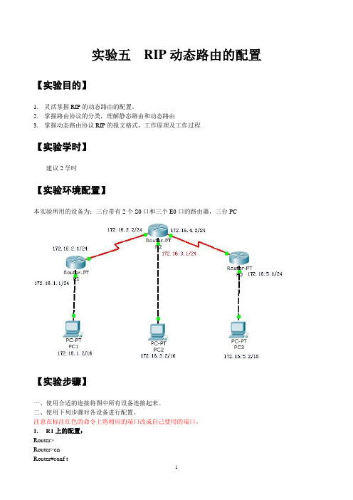
二、实验设备1.路由器、计算机、直通线、交叉线2.实验所用的拓扑图如图8-1所示。
图8-1 RIP路由拓扑三、实验步骤1.按照图8-1所示进行设备的连接和配置。
同理配置其他三个主机的IP地址、掩码和网关2.RouterA的基本配置如下:Router>enRouter#config tRouter(config)#int f0/0Router(config-if)#ip address 192.168.1.1 255.255.255.0 Router(config-if)#no shutdownRouter(config-if)#exitRouter(config)#int f0/1Router(config-if)#ip address 192.168. 2.1 255.255.255.0 Router(config-if)#no shutdownRouter(config-if)#endRouter#3.RouterB的基本配置如下:Router>enableRouter#config tRouter(config)#int f0/0Router(config-if)#ip address 192.168.2.2. 255.255.255.0 Router(config-if)#no shutdownRouter(config-if)#exitRouter(config)#int f0/1Router(config-if)#ip address 192.168.3.1 255.255.255.0Router(config-if)#no shutdownRouter(config-if)#endRouter#4. 测试PC1是否能互相Ping通pc3;(截图并说明原因)不能PING通,因为他的Destination host 没有reachable。
华为Rip实验练习
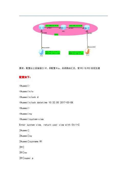
要求:配置以上设备接口IP,并配置Rip,关闭路由汇总,使PC1与PC2实现互通配置如下:<Huawei><Huawei>clo<Huawei>clock d<Huawei>clock datetime 10:32:00 2017-03-08<Huawei><Huawei>sy<Huawei>system-viewEnter system view, return user view with Ctrl+Z.[Huawei][Huawei]sy[Huawei]sysname R1[R1][R1]su[R1]super p[R1]super password c[R1]super password cipher 123456[R1][R1]us[R1]user-i[R1]user-interface v[R1]user-interface vty 0 4[R1-ui-vty0-4][R1-ui-vty0-4]auth[R1-ui-vty0-4]authentication-mode p[R1-ui-vty0-4]authentication-mode passwordPlease configure the login password (maximum length 16):123456 [R1-ui-vty0-4][R1-ui-vty0-4]se[R1-ui-vty0-4]set auth[R1-ui-vty0-4]set authentication p[R1-ui-vty0-4]set authentication password c[R1-ui-vty0-4]set authentication password cipher 123456[R1-ui-vty0-4][R1-ui-vty0-4]q[R1][R1]us[R1]user-i[R1]user-interface c[R1]user-interface console 0[R1-ui-console0][R1-ui-console0]auth[R1-ui-console0]authentication-mode p[R1-ui-console0]authentication-mode passwordPlease configure the login password (maximum length 16):123456 [R1-ui-console0][R1-ui-console0]se[R1-ui-console0]set auth[R1-ui-console0]set authentication p[R1-ui-console0]set authentication password c[R1-ui-console0]set authentication password cipher 123456[R1-ui-console0]q[R1][R1]aaa[R1-aaa]lo[R1-aaa]local-user admin pa[R1-aaa]local-user admin password c[R1-aaa]local-user admin password cipher admin123[R1-aaa][R1-aaa]lo[R1-aaa]local-user admin ser[R1-aaa]local-user admin service-type t[R1-aaa]local-user admin service-type telnet[R1-aaa][R1-aaa]q[R1][R1]int g0/0/0[R1-GigabitEthernet0/0/0]ip add 24[R1-GigabitEthernet0/0/0]Mar 8 2017 10:45:41-08:00 R1 %%01IFNET/4/LINK_STATE(l)[0]:The line protocol IPon the interface GigabitEthernet0/0/0 has entered the UP state.[R1-GigabitEthernet0/0/0][R1-GigabitEthernet0/0/0]un[R1-GigabitEthernet0/0/0]undo sh[R1-GigabitEthernet0/0/0]undo shutdownInfo: Interface GigabitEthernet0/0/0 is not shutdown.[R1-GigabitEthernet0/0/0]q[R1][R1]int g0/0/1[R1-GigabitEthernet0/0/1]ip add 24[R1-GigabitEthernet0/0/1]Mar 8 2017 10:46:24-08:00 R1 %%01IFNET/4/LINK_STATE(l)[1]:The line protocol IPon the interface GigabitEthernet0/0/1 has entered the UP state.[R1-GigabitEthernet0/0/1][R1-GigabitEthernet0/0/1]un[R1-GigabitEthernet0/0/1]undo sh[R1-GigabitEthernet0/0/1]undo shutdownInfo: Interface GigabitEthernet0/0/1 is not shutdown.[R1-GigabitEthernet0/0/1][R1-GigabitEthernet0/0/1]q[R1][R1]dis ip int br*down: administratively down^down: standby(l): loopback(s): spoofingThe number of interface that is UP in Physical is 3The number of interface that is DOWN in Physical is 1The number of interface that is UP in Protocol is 3The number of interface that is DOWN in Protocol is 1Interface IP Address/Mask Physical ProtocolGigabitEthernet0/0/0 up upGigabitEthernet0/0/1 up upGigabitEthernet0/0/2 unassigned down downNULL0 unassigned up up(s)[R1]q<R1><R1>saveThe current configuration will be written to the device.Are you sure to continue (y/n)[n]:yIt will take several minutes to save configuration file, please wait..........Configuration file had been saved successfullyNote: The configuration file will take effect after being activated<R1>Please check whether system data has been changed, and save data in timeConfiguration console time out, please press any key to log onPassword:<R1><R1><R1>sy<R1>system-viewEnter system view, return user view with Ctrl+Z.[R1]rip[R1-rip-1]ver[R1-rip-1]verify-source[R1-rip-1]ver[R1-rip-1]version 2[R1-rip-1]un[R1-rip-1]undo sum[R1-rip-1]undo summary[R1-rip-1][R1-rip-1]net[R1-rip-1]network[R1-rip-1]network The current configuration will be written to the device.Are you sure to continue (y/n)[n]:yIt will take several minutes to save configuration file, please wait.........Configuration file had been saved successfullyNote: The configuration file will take effect after being activated<R1><R1><R1><R1><R1>dis<R1>display ip rout<R1>display ip routing-tableRoute Flags: R - relay, D - download to fib------------------------------------------------------------------------------Routing Tables: PublicDestinations : 10 Routes : 10Destination/Mask Proto Pre Cost Flags NextHop InterfaceDirect 0 0 D InLoopBack0Direct 0 0 D InLoopBack0Direct 0 0 D InLoopBack0Direct 0 0 D GigabitEthernet0/0/0Direct 0 0 D GigabitEthernet0/0/0Direct 0 0 D GigabitEthernet0/0/0Direct 0 0 D GigabitEthernet0/0/1Direct 0 0 D GigabitEthernet 0/0/1Direct 0 0 D GigabitEthernet 0/0/1Direct 0 0 D InLoopBack0<R1>Password:Password:Password:<R1><R1><R1><R1>ping PING 56 data bytes, press CTRL_C to break Reply from bytes=56 Sequence=1 ttl=254 time=60 ms Reply from bytes=56 Sequence=2 ttl=254 time=40 ms Reply from bytes=56 Sequence=3 ttl=254 time=40 ms Reply from bytes=56 Sequence=4 ttl=254 time=40 ms Reply from bytes=56 Sequence=5 ttl=254 time=30 ms--- ping statistics ---5 packet(s) transmitted5 packet(s) received% packet lossround-trip min/avg/max = 30/42/60 ms<R1><R1><R1>ping PING 56 data bytes, press CTRL_C to break Request time outReply from bytes=56 Sequence=2 ttl=126 time=40 ms Reply from bytes=56 Sequence=3 ttl=126 time=50 ms Reply from bytes=56 Sequence=4 ttl=126 time=30 ms Reply from bytes=56 Sequence=5 ttl=126 time=40 ms--- ping statistics ---5 packet(s) transmitted4 packet(s) received% packet lossround-trip min/avg/max = 30/40/50 ms<R1><Huawei>clo<Huawei>clock d<Huawei>clock datetime 11:05:00 2017-03-08<Huawei><Huawei>sy<Huawei>system-viewEnter system view, return user view with Ctrl+Z. [Huawei][Huawei]sy[Huawei]sysname R2[R2]su[R2]super p[R2]super password c[R2]super password cipher 123456[R2][R2]us[R2]user-i[R2]user-interface v[R2]user-interface vty 0 4[R2-ui-vty0-4]auth[R2-ui-vty0-4]authentication-mode p[R2-ui-vty0-4]authentication-mode passwordPlease configure the login password (maximum length 16):123456 [R2-ui-vty0-4]se[R2-ui-vty0-4]set auth[R2-ui-vty0-4]set authentication p[R2-ui-vty0-4]set authentication password c[R2-ui-vty0-4]set authentication password cipher 123456[R2-ui-vty0-4]q[R2][R2]us[R2]user-i[R2]user-interface c[R2]user-interface console 0[R2-ui-console0]auth[R2-ui-console0]authentication-mode p[R2-ui-console0]authentication-mode passwordPlease configure the login password (maximum length 16):123456[R2-ui-console0]se[R2-ui-console0]set auth[R2-ui-console0]set authentication p[R2-ui-console0]set authentication password c[R2-ui-console0]set authentication password cipher 123456[R2-ui-console0]q[R2][R2]aaa[R2-aaa]lo[R2-aaa]local-user admin p[R2-aaa]local-user admin password c[R2-aaa]local-user admin password cipher admin1234[R2-aaa][R2-aaa]lo[R2-aaa]local-user admin ser[R2-aaa]local-user admin service-type tel[R2-aaa]local-user admin service-type telnet[R2-aaa][R2-aaa]q[R2][R2]int g[R2]int GigabitEthernet 0/0/0[R2-GigabitEthernet0/0/0]ip add 24[R2-GigabitEthernet0/0/0]Mar 8 2017 11:14:56-08:00 R2 %%01IFNET/4/LINK_STATE(l)[0]:The line protocol IPon the interface GigabitEthernet0/0/0 has entered the UP state.[R2-GigabitEthernet0/0/0]un[R2-GigabitEthernet0/0/0]undo sh[R2-GigabitEthernet0/0/0]undo shutdownInfo: Interface GigabitEthernet0/0/0 is not shutdown.[R2-GigabitEthernet0/0/0]q[R2][R2]int g0/0/1[R2-GigabitEthernet0/0/1]ip add 24[R2-GigabitEthernet0/0/1]Mar 8 2017 11:17:05-08:00 R2 %%01IFNET/4/LINK_STATE(l)[1]:The line protocol IPon the interface GigabitEthernet0/0/1 has entered the UP state.[R2-GigabitEthernet0/0/1]un[R2-GigabitEthernet0/0/1]undo sh[R2-GigabitEthernet0/0/1]undo shutdownInfo: Interface GigabitEthernet0/0/1 is not shutdown.[R2-GigabitEthernet0/0/1]q[R2][R2]dis ip int br*down: administratively down^down: standby(l): loopback(s): spoofingThe number of interface that is UP in Physical is 3The number of interface that is DOWN in Physical is 1The number of interface that is UP in Protocol is 3The number of interface that is DOWN in Protocol is 1Interface IP Address/Mask Physical ProtocolGigabitEthernet0/0/0 up upGigabitEthernet0/0/1 up upGigabitEthernet0/0/2 unassigned down downNULL0 unassigned up up(s)[R2][R2][R2][R2]q<R2>saveThe current configuration will be written to the device.Are you sure to continue (y/n)[n]:yIt will take several minutes to save configuration file, please wait..........Configuration file had been saved successfullyNote: The configuration file will take effect after being activated<R2>Please check whether system data has been changed, and save data in timeConfiguration console time out, please press any key to log onPassword:Password:<R2><R2>sy<R2>system-viewEnter system view, return user view with Ctrl+Z.[R2][R2][R2]rip[R2-rip-1]ver[R2-rip-1]verify-source[R2-rip-1]ver[R2-rip-1]version 2[R2-rip-1]un[R2-rip-1]undo sum[R2-rip-1]undo summary[R2-rip-1][R2-rip-1]net[R2-rip-1]network[R2-rip-1]network[R2]display ip rou[R2]display ip routing-tableRoute Flags: R - relay, D - download to fib------------------------------------------------------------------------------Routing Tables: PublicDestinations : 11 Routes : 11Destination/Mask Proto Pre Cost Flags NextHopInterfaceDirect 0 0 D InLoopBack0Direct 0 0 D InLoopBack0Direct 0 0 D InLoopBack0RIP 100 1 D GigabitEthernet0/0/0Direct 0 0 D GigabitEthernet0/0/0Direct 0 0 D GigabitEthernet0/0/0Direct 0 0 D GigabitEthernet0/0/0Direct 0 0 D GigabitEthernet0/0/1Direct 0 0 D GigabitEthernet0/0/1Direct 0 0 D GigabitEthernet0/0/1Direct 0 0 D InLoopBack0[R2]q<R2><R2>saveThe current configuration will be written to the device.Are you sure to continue (y/n)[n]:yIt will take several minutes to save configuration file, pleasewait.........Configuration file had been saved successfullyNote: The configuration file will take effect after being activated <R2>Password:<R2><R2>ping PING 56 data bytes, press CTRL_C to breakRequest time outReply from bytes=56 Sequence=2 ttl=127 time=50 msReply from bytes=56 Sequence=3 ttl=127 time=20 msReply from bytes=56 Sequence=4 ttl=127 time=20 msReply from bytes=56 Sequence=5 ttl=127 time=30 ms--- ping statistics ---5 packet(s) transmitted4 packet(s) received% packet lossround-trip min/avg/max = 20/30/50 ms<R2>ping PING 56 data bytes, press CTRL_C to breakReply from bytes=56 Sequence=1 ttl=255 time=60 msReply from bytes=56 Sequence=2 ttl=255 time=30 msReply from bytes=56 Sequence=3 ttl=255 time=40 msReply from bytes=56 Sequence=4 ttl=255 time=30 msReply from bytes=56 Sequence=5 ttl=255 time=30 ms--- ping statistics ---5 packet(s) transmitted5 packet(s) received% packet lossround-trip min/avg/max = 30/38/60 ms<R2>ping PING 56 data bytes, press CTRL_C to break Reply from bytes=56 Sequence=1 ttl=255 time=40 ms Reply from bytes=56 Sequence=2 ttl=255 time=20 ms Reply from bytes=56 Sequence=3 ttl=255 time=40 ms Reply from bytes=56 Sequence=4 ttl=255 time=110 ms Reply from bytes=56 Sequence=5 ttl=255 time=20 ms--- ping statistics ---5 packet(s) transmitted5 packet(s) received% packet lossround-trip min/avg/max = 20/46/110 ms<R2>ping PING 56 data bytes, press CTRL_C to break Request time outReply from bytes=56 Sequence=2 ttl=127 time=20 ms Reply from bytes=56 Sequence=3 ttl=127 time=30 ms Reply from bytes=56 Sequence=4 ttl=127 time=30 ms Reply from bytes=56 Sequence=5 ttl=127 time=40 ms--- ping statistics ---5 packet(s) transmitted4 packet(s) received% packet lossround-trip min/avg/max = 20/30/40 ms<R2><Huawei><Huawei><Huawei>clo<Huawei>clock d<Huawei>clock datetime 13:56:00 2017-03-08<Huawei>sy<Huawei>system-viewEnter system view, return user view with Ctrl+Z. [Huawei]sy[Huawei]sysname R3[R3]su[R3]super p[R3]super password c[R3]super password cipher 123456[R3][R3]us[R3]user-i[R3]user-interface v[R3]user-interface vty 0 4[R3-ui-vty0-4][R3-ui-vty0-4]auth[R3-ui-vty0-4]authentication-mode p[R3-ui-vty0-4]authentication-mode passwordPlease configure the login password (maximum length 16):123456 [R3-ui-vty0-4]se[R3-ui-vty0-4]set auth[R3-ui-vty0-4]set authentication p[R3-ui-vty0-4]set authentication password c[R3-ui-vty0-4]set authentication password cipher 123456[R3-ui-vty0-4][R3-ui-vty0-4]q[R3][R3]us[R3]user-i[R3]user-interface c[R3]user-interface console 0[R3-ui-console0]auth[R3-ui-console0]authentication-mode p[R3-ui-console0]authentication-mode passwordPlease configure the login password (maximum length 16):123456 [R3-ui-console0]se[R3-ui-console0]set auth[R3-ui-console0]set authentication p[R3-ui-console0]set authentication password c[R3-ui-console0]set authentication password cipher 123456[R3-ui-console0]q[R3][R3]aaa[R3-aaa]lo[R3-aaa]local-user admin p[R3-aaa]local-user admin password c[R3-aaa]local-user admin password cipher admin123[R3-aaa][R3-aaa]lo[R3-aaa]local-user admin ser[R3-aaa]local-user admin service-type t[R3-aaa]local-user admin service-type telnet[R3-aaa]q[R3][R3]int g0/0/0[R3-GigabitEthernet0/0/0]ip add 24[R3-GigabitEthernet0/0/0]Mar 8 2017 14:01:20-08:00 R3 %%01IFNET/4/LINK_STATE(l)[0]:The line protocol IPon the interface GigabitEthernet0/0/0 has entered the UP state.[R3-GigabitEthernet0/0/0]un[R3-GigabitEthernet0/0/0]undo sh[R3-GigabitEthernet0/0/0]undo shutdownInfo: Interface GigabitEthernet0/0/0 is not shutdown.[R3-GigabitEthernet0/0/0]q[R3][R3][R3][R3]int g0/0/1[R3-GigabitEthernet0/0/1]ip add 24[R3-GigabitEthernet0/0/1]Mar 8 2017 14:04:49-08:00 R3 %%01IFNET/4/LINK_STATE(l)[2]:The line protocol IPon the interface GigabitEthernet0/0/1 has entered the UP state.[R3-GigabitEthernet0/0/1][R3-GigabitEthernet0/0/1]un[R3-GigabitEthernet0/0/1]undo sh[R3-GigabitEthernet0/0/1]undo shutdownInfo: Interface GigabitEthernet0/0/1 is not shutdown.[R3-GigabitEthernet0/0/1]q[R3][R3]dis ip int br*down: administratively down^down: standby(l): loopback(s): spoofingThe number of interface that is UP in Physical is 3The number of interface that is DOWN in Physical is 1The number of interface that is UP in Protocol is 3The number of interface that is DOWN in Protocol is 1Interface IP Address/Mask Physical ProtocolGigabitEthernet0/0/0 up up GigabitEthernet0/0/1 up upGigabitEthernet0/0/2 unassigned down downNULL0 unassigned up up(s)[R3]q<R3>saveThe current configuration will be written to the device.Are you sure to continue (y/n)[n]:yIt will take several minutes to save configuration file, please wait..........Configuration file had been saved successfullyNote: The configuration file will take effect after being activated<R3><R3><R3><R3>sy<R3>system-viewEnter system view, return user view with Ctrl+Z.[R3][R3]rip[R3-rip-1][R3-rip-1]ver[R3-rip-1]verify-source[R3-rip-1][R3-rip-1]ver[R3-rip-1]version 2[R3-rip-1][R3-rip-1]net[R3-rip-1]network[R3-rip-1]network[R3]display ip ro[R3]display ip routing-tableRoute Flags: R - relay, D - download to fib------------------------------------------------------------------------------Routing Tables: PublicDestinations : 12 Routes : 12Destination/Mask Proto Pre Cost Flags NextHop InterfaceDirect 0 0 D InLoopBack0Direct 0 0 D InLoopBack0Direct 0 0 D InLoopBack0RIP 100 2 D GigabitEthernet0/0/0Direct 0 0 D GigabitEthernet0/0/1Direct 0 0 D GigabitEthernet0/0/1Direct 0 0 D GigabitEthernet0/0/1RIP 100 1 D GigabitEthernet0/0/0Direct 0 0 D GigabitEthernet0/0/0Direct 0 0 D GigabitEthernet0/0/0Direct 0 0 D GigabitEthernet0/0/0Direct 0 0 D InLoopBack0[R3]q<R3>saveThe current configuration will be written to the device.Are you sure to continue (y/n)[n]:yIt will take several minutes to save configuration file, please wait........Configuration file had been saved successfullyNote: The configuration file will take effect after being activated <R3><R3><R3><R3>ping PING 56 data bytes, press CTRL_C to breakRequest time outReply from bytes=56 Sequence=2 ttl=254 time=110 msReply from bytes=56 Sequence=3 ttl=254 time=40 msReply from bytes=56 Sequence=4 ttl=254 time=40 msReply from bytes=56 Sequence=5 ttl=254 time=30 ms--- ping statistics ---5 packet(s) transmitted4 packet(s) received% packet lossround-trip min/avg/max = 30/55/110 ms<R3>ping PING 56 data bytes, press CTRL_C to break Request time outReply from bytes=56 Sequence=2 ttl=126 time=40 ms Reply from bytes=56 Sequence=3 ttl=126 time=30 ms Reply from bytes=56 Sequence=4 ttl=126 time=60 ms Reply from bytes=56 Sequence=5 ttl=126 time=30 ms--- ping statistics ---5 packet(s) transmitted4 packet(s) received% packet lossround-trip min/avg/max = 30/40/60 ms<R3>PC1与PC2测试连通性情况。
RIP协议分析实验实验报告
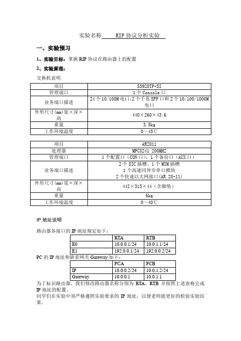
实验名称RIP协议分析实验一、实验预习1、实验目标:掌握RIP协议在路由器上的配置2、实验原理:交换机说明IP地址说明PC的IPIP地址的配置。
同学们在实验中须严格遵照实验要求的IP地址,以便老师能更好的检验实验结果。
说明:实际应用中,IP地址是根据实际情况进行灵活规划的。
3、实验设备及材料:1) 1台华为Quidway S3928TP以太网交换机2) 2台华为Quidway AR 2811路由器3) 2台PC4) 专用配置电缆2根,标准网线9根4、实验流程或装置示意图:二、实验内容方法步骤及现象:第一步:首先确认实验设备依照组网图3-2正确连接;第二步:PC通过CONSOLE口连接上Quidway AR2811路由器;第三步:执行如下命令显示RTA路由表,并记录结果:[Quidway]display ip routing-table参考结果:Routing Tables:Destination/Mask Proto Pref Metric Nexthop Interface127.0.0.0/8 Direct 0 0 127.0.0.1 LoopBack0127.0.0.1/32 Direct 0 0 127.0.0.1 LoopBack0第四步:配置RTA路由器接口和PC的IP地址,具体配置命令如下:[Quidway]sysname RT A[RT A]int e0[RT A-Ethernet0]ip addr 10.0.0.1 24[RT A-Ethernet0]int e1[RT A-Ethernet1]ip addr 192.0.0.1 24第五步:执行如下命令显示RTA配置信息,并记录结果:[RT A]display current-configuration参考结果:Now create configuration...Current configuration!version 1.74firewall enablesysname RTAencrypt-card fast-switch!interface Aux0async mode flowphy-mru 0link-protocol ppp!interface Ethernet0ip address 10.0.0.1 255.255.255.0!interface Ethernet 1ip address 192.0.0.1 255.255.255.0!interface Serial0link-protocol ppp!interface Serial1link-protocol ppp!return第六步:执行如下命令显示RTA路由表,并记录结果:[RT A]display ip routing-table参考结果:Routing Tables:Destination/Mask Proto Pref Metric Nexthop Interface127.0.0.0/8 Direct 0 0 127.0.0.1 LoopBack0127.0.0.1/32 Direct 0 0 127.0.0.1 LoopBack0192.0.0.0/24 Direct 0 0 192.0.0.1 Ethernet0192.0.0.1/32 Direct 0 0 127.0.0.1 LoopBack0192.0.0.1/32 Direct 0 0 192.0.0.1 Ethernet010.0.0.0/24 Direct 0 0 10.0.0.1 Ethernet010.0.0.1/32 Direct 0 0 127.0.0.1 LoopBack0第七步:PCB通过CONSOLE口连接上Quidway AR2811路由器RTB;第八步:执行如下命令显示RTB路由表,并记录结果:[Quidway]display ip routing-table参考结果:Routing Tables:Destination/Mask Proto Pref Metric Nexthop Interface127.0.0.0/8 Direct 0 0 127.0.0.1 LoopBack0127.0.0.1/32 Direct 0 0 127.0.0.1 LoopBack0第九步:配置RTB路由器接口和PC的IP地址,具体配置命令如下:[Quidway]sysname RTB[RTB]int e0[RTB-Ethernet0]ip addr 10.0.1.1 24[RTB-Ethernet0]int e1[RTB-Ethernet1]ip addr 192.0.0.2 24第十步:执行如下命令显示RTB配置信息,并记录结果:[RT A]display current-configuration参考结果:Now create configuration...Current configuration!version 1.74firewall enablesysname RTBencrypt-card fast-switch!interface Aux0async mode flowphy-mru 0link-protocol ppp!interface Ethernet0ip address 10.0.1.1 255.255.255.0!interface Ethernet 1ip address 192.0.0.2 255.255.255.0!interface Serial0link-protocol ppp!interface Serial1link-protocol ppp!return第十一步:执行如下命令显示RTB路由表,并记录结果:[RTB]display ip routing-table参考结果:Routing Tables:Destination/Mask Proto Pref Metric Nexthop Interface127.0.0.0/8 Direct 0 0 127.0.0.1 LoopBack0127.0.0.1/32 Direct 0 0 127.0.0.1 LoopBack0192.0.0.0/24 Direct 0 0 192.0.0.1 Ethernet0192.0.0.2/32 Direct 0 0 127.0.0.1 LoopBack0192.0.0.1/32 Direct 0 0 192.0.0.1 Ethernet110.0.0.0/24 Direct 0 0 10.0.1.1 Ethernet010.0.1.1/32 Direct 0 0 127.0.0.1 LoopBack0第十二步:完成上述配置之后,用ping命令测试网络互通性;思考题:观察两两个以太网段能否互通,并解释原因(参考答案:仔细看看路由表就可以明白,路由器还没有相关的路由);第十三步:在RTA上配置RIP协议,命令如下;[RT A]rip[RT A-rip]network all第十四步:执行如下命令显示RTA配置信息,并记录结果:[RT A]display current-configuration参考结果:Now create configuration...Current configuration!version 1.74firewall enablesysname RTAencrypt-card fast-switch!interface Aux0async mode flowphy-mru 0link-protocol ppp!interface Ethernet0ip address 10.0.0.1 255.255.255.0!interface Ethernet 1ip address 192.0.0.1 255.255.255.0!interface Serial0link-protocol ppp!interface Serial1link-protocol ppp!quitripnetwork all!quit!return思考题:试分析与第五步记录的结果有什么不同,并解释原因;第十五步:执行如下命令显示RTA路由表,并记录结果:[RT A]display ip routing-table参考结果:Routing Tables:Destination/Mask Proto Pref Metric Nexthop Interface127.0.0.0/8 Direct 0 0 127.0.0.1 LoopBack0127.0.0.1/32 Direct 0 0 127.0.0.1 LoopBack0192.0.0.0/24 Direct 0 0 192.0.0.1 Ethernet0192.0.0.1/32 Direct 0 0 127.0.0.1 LoopBack0192.0.0.1/32 Direct 0 0 192.0.0.1 Ethernet010.0.0.0/24 Direct 0 0 10.0.0.1 Ethernet010.0.0.1/32 Direct 0 0 127.0.0.1 LoopBack010.0.1.0/24 RIP 100 1 192.0.0.2 Ethernet1 思考题:试分析与第六步记录的结果有什么不同,并解释原因;第十六步:在RTB上配置RIP协议,命令如下;[RTB]rip[RTB-rip]network all第十七步:执行如下命令显示RTB配置信息,并记录结果:[RTB]display current-configuration参考结果:Now create configuration...Current configuration!version 1.74firewall enablesysname RTBencrypt-card fast-switch!interface Aux0async mode flowphy-mru 0link-protocol ppp!interface Ethernet0ip address 10.0.1.1 255.255.255.0!interface Ethernet 1ip address 192.0.0.2 255.255.255.0!interface Serial0link-protocol ppp!interface Serial1link-protocol ppp!quitripnetwork all!quit!return思考题:试分析与第十步记录的结果有什么不同,并解释原因;第十八步:执行如下命令显示RTA路由表,并记录结果:[RT A]display ip routing-table参考结果:Routing Tables:Destination/Mask Proto Pref Metric Nexthop Interface127.0.0.0/8 Direct 0 0 127.0.0.1 LoopBack0127.0.0.1/32 Direct 0 0 127.0.0.1 LoopBack0192.0.0.0/24 Direct 0 0 192.0.0.1 Ethernet0192.0.0.2/32 Direct 0 0 127.0.0.1 LoopBack0192.0.0.1/32 Direct 0 0 192.0.0.1 Ethernet110.0.0.0/24 Direct 0 0 10.0.1.1 Ethernet010.0.1.1/32 Direct 0 0 127.0.0.1 LoopBack010.0.0.0/24 RIP 100 1 192.0.0.1 Ethernet1思考题:试分析与第十一步记录的结果有什么不同,并解释原因;第十九步:完成上述配置之后,用ping命令测试网络互通性;思考题:观察两两个以太网段能否互通,并解释原因(与第十二步分析做对比);第二十步:现在我们可以看看RIP是怎样发现路由的,在特权模式下打开RIP协议调试开关,有如下信息在路由器之间传递,它们完成了路由的交换,并形成新的路由。
rip实验报告
一.配置RIP(分别配置RIP1和RIP2)
1.配置RIP协议,使各设备连通
已经完成。
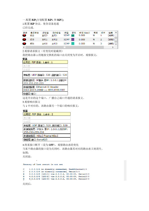
2.观察请求报文(有变化时能截到)
我把路由器1的链接交换机的端口由关闭变为开启时,观察报文:
这是开启的这个端口,广播自己端口开通的请求报文。
3.观察响应报文
与1中对应的,该路由器另一个端口的响应报文:
4.将某接口断开(设为OFF),观察路由表的变化
当某个路由器的接口设为关闭时,该路由器其对应的路由表立刻消失。
如图:
关闭前:
关闭后:
可见:与该端口有关的路由表,立刻消失。
其它路由器的变化:
立刻看的:
一段时间后:
可见其它路由器的路由表在开始时并没有变化,在一段时间后才会消失。
可见rip的坏消息传播的比较慢。
5.将某接口接通(设为ON),观察路由表的变化
将4中关闭的端口设为开启:
该路由器的该端口相连的路由表立刻出现:
其它路由器有关的路由表也立刻出现(不要怀疑我的手速):
可见,好消息的传播,明显要比坏消息要迅速许多。
8实训八RIP动态路由配置答案

实训八路由器的RIP动态路由配置一、实训目的和要求1、掌握路由器动态路由的概念、动态路由与静态路由的区别、动态路由的发现方法。
2、掌握路由器动态路由的基本配置命令和配置方法。
二、实训内容为路由器配置动态路由,并测试连通性。
三、命令格式Router(config)#ip routing ;启动路由转发功能Router(config)#router rip ;进入RIP协议设置状态Router(config-router)#network [network号];指定与该路由器相连的网络指定的网络号一定不能包含子网信息。
可以指定多重network命令。
只能通过这些网络的接口发送和接收RIP路由更新信息。
RIP发送更新信息到指定网络的接口上,同时,如果接口网络未指定,则得不到RIP更新通告。
Router(config-router)#exit ;退出RIP协议设置状态Router(config)#debug ip rip ;显示RIP协议操作信息,路由器是否正在发送或接收更新信息Router(config)#show ip protocol ;显示当前路由协议情况四、实训步骤在画图时选择RouterC的s0、s1端口作为DCE端口。
(1)pc机的地址如下。
ip address subnet mask default-gateway HostA 10.65.1.1 255.255.0.0 10.65.1.2HostB 10.66.1.1 255.255.0.0 10.66.1.2HostC 10.69.1.1 255.255.0.0 10.69.1.2HostD 10.70.1.1 255.255.0.0 10.70.1.2(2)对RouterA进行配置,在配置好各端口ip地址后激活该端口。
各端口ip地址如下。
f0/0:ip地址10.65.1.2,子网掩码255.255.0.0。
f0/1:ip地址10.66.1.2,子网掩码255.255.0.0。
实验6-RIP路由实验

实验6-RIP路由实验实验六RIP路由⼀、实验课时:2学时⼆、实验⽬的熟悉动态路由的基本特点。
掌握RIP路由选择协议的要点。
掌握给路由器配置动态路由的⽅法。
三、实验环境两台⽤于测试的计算机路由器两台⽹线若⼲四、实验过程⽤串⼝线连接两台路由器。
⽤⽹线将两台计算机分别和两台路由器相连在计算机上配置路由器的命令,配置两台路由器的RIP路由选择协议。
使⽤ping命令测试⽤于实验的两台计算机的连通性。
五、实验内容配置路由器的主机名等基本配置。
配置路由器接⼝的ip地址。
配置路由器的RIP路由。
在主机上ping,连通说明实验成功,否则实验不成功。
撰写实验报告。
六、实验步骤:1、⽤⽹线连接两台路由器与两台计算机注意,⽤串⼝线连接路由器时,Router1为DCE端,Router2为DTE端。
2、在路由器Router1上配置接⼝的IP地址和串⼝上的时钟频率Router>enableRouter#configure terminalRouter(config)#hostname Router1Router1 (config)#no ip domain-lookupRouter1 (config)#line console 0Router1 (config-line)#logging synchronousRouter1 (config-line)#exec-timeout 0 0Router1 (config-line)#exitRouter1(config)# int fa0/0Router1(config-if)# ip address 172.16.1.1 255.255.255.0Router1(config-if)# no shutdownRouter1(config-if)# exitRouter1(config)# int s0/0/0Router1(config-if)# ip address 172.16.2.1 255.255.255.0Router1(config-if)#clock rate 64000Router1(config-if)# no shutdownRouter1(config-if)#exit3、在路由器Router1上配置RIP V2路由协议Router1(config)# router rip !创建RIP路由进程Router1(config-router)#version 2 !定义RIP版本Router1(config-router)#network 172.16.0.0 !定义关联⽹络(必须是直连的主类⽹络地址)4、在路由器Router2上配置接⼝的IP地址Router>enableRouter#configure terminalRouter(config)#hostname Router2Router2 (config)#no ip domain-lookupRouter2 (config)#line console 0Router2 (config-line)#logging synchronousRouter2 (config-line)#exec-timeout 0 0Router2 (config-line)#exitRouter2(config)# interface fastethernet 0/0Router2(config-if)# ip address 172.16.3.2 255.255.255.0Router2(config-if)# no shutdownRouter2(config-if)#exitRouter2(config)# interface serial 0/0/0Router2(config-if)# ip address 172.16.2.2 255.255.255.0Router2(config-if)# no shutdownRouter2(config-if)#exit5、在路由器Router2上配置RIP V2路由协议Router2(config)# router ripRouter1(config-router)#version 2Router2(config-router)#network 172.16.0.06、测试⽹络的连通性C:\>ping 172.16.3.22 !从PC1 ping PC2结果显⽰⽹络是连通的【注意事项】当定义R I P版本后,路由器只接收该版本的路由信息;缺省情况下,路由器接收两个R I P版本的路由信息,但只发送版本1的路由信息;在三层交换机上配置R I P v2与在路由器上配置⼀样。
华为实训 路由器动态路由协议RIP的配置

实训8路由器动态路由协议RIP的配置【实训目的】(1)熟悉路由器的基本配置;(2)掌握RIP协议的配置方法;(3)掌握查看通过动态路由协议RIP学习产生的路由;(4)熟悉广域网线缆的连接方式;【实训技术原理】RIP(Routing Information Protocols,路由信息协议)是应用较早、使用较普通的IGP内部网关协议,适用用于小型同类网络,是距离矢量协议;RIP协议跳数做为衡量路径开销的,RIP协议里规定最大跳数为15;RIP协议有两个版本:RIPv1和RIPv2,RIPv1属于有类路由协议,不支持VLSM,以广播形式进行路由信息的更新,更新周期为30秒;RIPv2属于无类路由协议,支持VLSM,以组播形式进行路由更新。
【实现功能】实现网络的互连互通,从而实现信息的共享和传递。
【实训背景描述】学校有新旧两个校区,每个校区是一个独立的局域网,为了使新旧校区能够正常相互通讯,共享资源。
每个校区出口利用一台路由器进行连接,两台路由器间学校申请了一条2M的DDN专线进行相连,为了简化网管的管理维护工作,学校决定采用RIP协议实现两校区路由互通。
【实训设备】MSR20-20(2台),S3610(2台),PC(2台)、直连线(4条)V.35线缆(1条)【实训内容】(1)在路由器R1、R2上配置接口的IP地址;(2)查看路由器生成的直连路由;(3)在路由器R1、R2上配置RIP协议;(4)验证R1、R2是否自动学习了其他网段的路由信息;(5)将PC1、PC2主机默认网关分别设置为与路由器接口E0/0IP地址。
(6)PC1、PC2主机之间可以互相通信;【实训拓扑图】E0/0E0/0S1/0S1/0172.16.1.0/24172.16.2.0/24R1R2【实训步骤】(1)配置主机Ip 地址、默认网关。
PC1:172.16.1.2/24172.16.1.1PC2:172.16.2.2/24172.16.2.1(2)登陆路由器R1、R2上配置以太口的IP 地址R1的配置:[Router]interface ethernet 0/0[Router-Ethernet0/0]ip address 172.16.1.1255.255.255.0[Router-Ethernet0/0]quit路由器R2配置:[Router]interface ethernet 0/0[Router-Ethernet0/0]ip address 172.16.3.1255.255.255.0[Router-Ethernet0/0](3)登录路由器R1、R2上配置接口的IP 地址R1的配置:[Router-Ethernet0/0]interface serial 1/0[Router-Serial1/0]ip address 172.16.2.1255.255.255.0[Router-Serial1/0]undo shutdownR2配置如上,同学们自己来作。
hcip综合实验12题

hcip综合实验12题1. 在华为交换机上配置VLAN时,以下哪个命令用于将接口加入到VLAN中?A. vlan batchB. vlan accessC. port link-type accessD. port default vlan答案: C. port link-type access 加上port access vlan 命令用于将接口加入VLAN。
2. 在华为路由器上配置OSPF时,哪个命令用于指定路由器ID?A. ospf router-idB. router idC. ospf idD. router ospf id答案: A. ospf router-id3. 如何检查华为交换机上的VLAN配置?A. display vlanB. show vlanC. vlan displayD. list vlan答案: A. display vlan4. 在华为路由器上配置静态路由时,哪个参数表示下一跳地址?A. nexthopB. gatewayC. hopD. jump答案: A. nexthop5. 在华为设备上配置STP(生成树协议)时,哪个命令用于启用STP?A. stp enableB. spanning-tree enableC. stp onD. enable stp答案: A. stp enable(注意:实际命令可能因设备型号和系统版本而异,但通常接近此格式。
)6. 在华为交换机上,哪个命令用于查看MAC地址表?A. display mac-addressB. show mac address-tableC. mac displayD. list mac答案: A. display mac-address7. 在华为路由器上配置NAT时,哪个命令用于定义内部全局地址池?A. nat address-groupB. nat poolC. ip nat poolD. global address-pool答案: C. ip nat pool8. 华为路由器上查看OSPF邻居状态的命令是什么?A. display ospf peerB. show ip ospf neighborC. ospf display neighborD. list ospf peers答案: A. display ospf peer(注意:实际命令可能因设备型号和系统版本而异,但通常接近此格式。
计算机网络实验指导基于华为平台 实验报告 实验4.4.1 路由器配置RIPv1基本功能

实验报告
实验名称:实验4.4.1:路由器配置RIPVl基本功能
学院:班级:学号:姓名:
步骤7:
1.请将创建的网络拓扑的截图粘贴到实验报告中。
2.请将路由器RTA的IP路由表的截图粘贴到实验报告中。
每条RlP路由的掩码分别
是多少?在截图中标出这些RlP路由。
3.请将路由器RTB的IP路由表的截图粘贴到实验报告中。
每条RIP路由的掩码分别
是多少?在截图中标出这些RlP路由。
4.请将路由器RTC的IP路由表的截图粘贴到实验报告中。
每条RIP路由的掩码分别
是多少?在截图中标出这些RlP路由。
5.PC-IO-I能Ping通PC-50-1吗?请将Ping命令结果的截图粘贴到实验报告中。
6.PC-IO-I到PC-50-1的路由是什么?请将从PC-IO-I发出的“tracert11.1.50.H”命令结
果的截图粘贴到实验报告中。
步骤8:
8.RlPVl报文类型有几种?它们分别是什么?
9.根据标准,RIPvl路由更新的间隔时间为多长?
10.RIPVl使用哪个协议传输RIP报文?源端口号和目的端口号分别是多少?
11.RTB发出的RIPVl路由更新报文的目的IP地址是什么?是什么类型的IP地址?
12.RTB发出的RIPVl路由更新报文中有几条路由?每条路由包含哪些信息?请将抓
取的更新路由报文包含的路由信息的截图粘贴到实验报告中。
实验静态路由与RIP路由协议设置参考答案

实验11:静态路由协议和R I P路由协议设置一、实验目的:熟悉静态路由和RIP路由协议的配置原理,掌握它的配置方法。
二、实验拓扑如下:创建以下拓扑结构并配置路由器,使得各路由器(静态和动态两种)可以相互ping得通。
三、实验步骤:1、首先按上图连接好路由器注意:路由器通常通过串行端口连接广域网络,因此路由器通常是DTE设备,modem、GV转换器等等传输设备通常被规定为DCE。
其实对于标准的串行端口,通常从外观就能判断是DTE还是DCE,DTE是针头(俗称公头),DCE是孔头(俗称母头),这样两种接口才能接在一起。
比如一台路由器,它处于网络的边缘,它有一个S0口需要从另一台路由器中学习到一些参数,具体实施时,我们就不需在这个S0口配“时钟速率”,它从对方学到。
这时它就是DTE,而对方就是DCE。
①添加路由的模块接口,如下图所示:②连线的时候注意不同的接口,连线选择DTE线,如下图所示:③设置之前需要打开对应的端口的电源,如图所示:2、按拓扑图规划IP 地址:A :S0/0 :/24 S0/1:1/24B :S0/0 :172.16.10.2/24 S0/1:172.16.20.1/24D :S0/0 :172.16.30.2/24 S0/1:172.16.40.1/24在各路由器上配置IP地址,保证在链路的连通性如:A(config)# int S0/0A(config-if)#ip addressA(config-if)#no shutdownA(config)#int S0/1A(config-if)#ip addressA(config-if)#no shutdown同样道理同学们配置余下的三个路由器。
请记着配置时钟频率:路由器的接口模式下:Router(config-if)#clock rate 128000实验过程可以通过思科虚拟器的操作界面进行设置,但最好通过路由命令来进行配置,视窗操作中设置路由端口需设置以下内容,如下图所示:3、在每个路由器上配置静态路由协议命令格式:ip route 目标地址段目标地址子网掩码下一跳地址(即距离此路由器最近相连的S0地址)配置A的静态路由协议协议:A(config)#endA#copy run start同样道理同学们配置余下的三个路由器的静态路由协议。
【精编范文】华为rip-word范文模板 (19页)

本文部分内容来自网络整理,本司不为其真实性负责,如有异议或侵权请及时联系,本司将立即删除!== 本文为word格式,下载后可方便编辑和修改! ==华为rip篇一:201X-07-24 华为的RIP实验华为的RIP配置实验1 验证RIPv1的路由更新规则:R1发送更新R1向R2广播的网络或子网是否与源接口(发送路由更新)处于同一主网。
1 如果不是:汇总成主类网络,不携带掩码,广播出去2 如果是同一主网:检查条目是否与发送接口掩码是否一致A:一致:发送该条目B:不一致:忽略该条目R2接收更新R2从R1接收的路由条目与接口的网络是否处于同一主网。
1 如果是同一主网:直接将接收接口的掩码给予该条目并接收2 如果不是:查看路由表中是否存在该主网的任意子网A:如果不存在:给予该条目一个有类网络掩码,接收并放入路由表B:如果存在任意子网:忽略该条目地址配置省略,现在配置RIPR1上的配置:[R1]rip 1[R1-rip-1]version 1[R1-rip-1]undo summary[R1-rip-1]net 10.0.0.0[R1-rip-1]net 172.16.0.0[R1-rip-1]quitR2上的配置:[R2]rip 1[R2-rip-1]version 1[R2-rip-1]net 10.0.0.0[R2-rip-1]undo summary[R2-rip-1]quitR3上的配置:[R3]rip 1[R3-rip-1]version 1[R3-rip-1]net 10.0.0.0[R3-rip-1]net 172.16.0.0[R3-rip-1]undo summary[R3-rip-1]quit查看个路由器的路由表R1的路由表为:[R1]dis ip routing-tableRoute Flags: R - relay, D - download to fib------------------------------------------------------------------------------Routing Tables: PublicDestinations : 14 Routes : 14Destination/Mask ProtoPre CostFlags NextHopInterface10.0.12.0/24 Direct 0 0 D10.0.12.1 Ethernet0/0/0 10.0.12.1/32 Direct0 0 D127.0.0.1 Ethernet0/0/0 10.0.15.0/24 Direct 0 0 D10.0.15.1 LoopBack2 10.0.15.1/32 Direct 0 0 D127.0.0.1 LoopBack210.0.16.0/25 Direct 0 0 D10.0.16.1 LoopBack3 10.0.16.1/32 Direct 0 0D127.0.0.1 LoopBack310.0.23.0/24 RIP 100 1 D10.0.12.2 Ethernet0/0/0 10.0.33.0/24 RIP 1002 D10.0.12.2 Ethernet0/0/0 127.0.0.0/8Direct 0 0 D127.0.0.1 InLoopBack0 127.0.0.1/32 Direct 0 0 D127.0.0.1InLoopBack0172.16.0.0/24 Direct 0 0 D172.16.0.1LoopBack0172.16.0.1/32 Direct 0 0 D127.0.0.1 LoopBack0172.16.1.0/25 Direct 0 0 D172.16.1.1LoopBack1172.16.1.1/32 Direct 0 0 D127.0.0.1 LoopBack1R1的路由表表明没有收到R3上172.16.0.10的路由条目,原因:R3在E0/0/0发送172.16.0.10路由更新时,由于172.16.0.10路由条目的主类网络与10.0.23.3的主类网络不是同一网段,根据RIPv1的更新规则,该路由将汇总成主类网络172.16.0.0,不携带掩码,广播出去。
实验05(2) RIP路由配置综合练习
实验五RIP动态路由的配置【实验目的】1.灵活掌握RIP的动态路由的配置。
2.掌握路由协议的分类,理解静态路由和动态路由3.掌握动态路由协议RIP的报文格式,工作原理及工作过程【实验学时】建议2学时【实验环境配置】本实验所用的设备为:三台带有2个S0口和三个E0口的路由器,三台PC【实验步骤】一、使用合适的连接将图中所有设备连接起来。
二、使用下列步骤对各设备进行配置。
注意在标注红色的命令上将相应的端口改成自己使用的端口。
1.R1上的配置:Router>Router>enRouter#conf tRouter(config)#host r1r1(config)#int e0r1(config-if)#ip add 172.16.1.1 255.255.255.0r1(config-if)#no shutdownr1(config-if)#exitr1(config)#int s0r1(config-if)#ip add 172.16.2.1 255.255.255.0r1(config-if)#no shutdownr1(config-if)#clock rate 56000r1(config-if)#no shutdownr1(config-if)#exitr1(config)#router ripr1(config-router)#net 172.16.0.0r1(config-router)#^ZRIP协议启用前的路由表r1#show ip routeCodes: C - connected, S - static, I - IGRP, R - RIP, M - mobile, B - BGPD - EIGRP, EX - EIGRP external, O - OSPF, IA - OSPF inter areaE1 - OSPF external type 1, E2 - OSPF external type 2, E - EGPi - IS-IS, L1 - IS-IS level-1, L2 - IS-IS level-2, * - candidate defaultU - per-user static routeGateway of last resort is not setC 172.16.1.0/24 is directly connected, Ethernet0C 172.16.2.0/24 is directly connected, Serial0RIP协议启用后的路由表r1#show ip routeCodes: C - connected, S - static, I - IGRP, R - RIP, M - mobile, B - BGPD - EIGRP, EX - EIGRP external, O - OSPF, IA - OSPF inter areaE1 - OSPF external type 1, E2 - OSPF external type 2, E - EGPi - IS-IS, L1 - IS-IS level-1, L2 - IS-IS level-2, * - candidate defaultU - per-user static routeGateway of last resort is not setC 172.16.1.0/24 is directly connected, Ethernet0C 172.16.2.0/24 is directly connected, Serial0R 172.16.3.0/24 [120/1] via 172.16.2.2, 00:01:37, Serial0R 172.16.4.0/24 [120/1] via 172.16.2.2, 00:07:21, Serial0R 172.16.5.0/24 [120/2] via 172.16.2.2, 00:05:21, Serial02.R2上的配置:Router>Router>enRouter#conf tRouter(config)#host r2r2(config)#int s1r2(config-if)#ip add 172.16.2.2 255.255.255.0r2(config-if)#no shutdownr2(config-if)#exitr2(config)#int s0r2(config-if)#ip add 172.16.4.1 255.255.255.0r2(config-if)#clock rate 56000r2(config-if)#no shutdownr2(config-if)#exitr2(config)#int e0r2(config-if)#ip add 172.16.3.1 255.255.255.0r2(config-if)#no shutdownr2(config-if)#exitr2(config)#router ripr2(config-router)#net 172.16.0.0r2(config-router)#^Zr2#show ip routeCodes: C - connected, S - static, I - IGRP, R - RIP, M - mobile, B - BGPD - EIGRP, EX - EIGRP external, O - OSPF, IA - OSPF inter areaE1 - OSPF external type 1, E2 - OSPF external type 2, E - EGPi - IS-IS, L1 - IS-IS level-1, L2 - IS-IS level-2, * - candidate defaultU - per-user static routeGateway of last resort is not setC 172.16.2.0/24 is directly connected, Serial1C 172.16.3.0/24 is directly connected, Ethernet0C 172.16.4.0/24 is directly connected, Serial0R 172.16.1.0/24 [120/1] via 172.16.2.1, 00:09:13, Serial1R 172.16.5.0/24 [120/1] via 172.16.4.2, 00:09:13, Serial03.R3上的配置:Router>Router>enRouter#conf tRouter(config)#int s1Router(config-if)#ip add 172.16.4.2 255.255.255.0Router(config-if)#no shutdownRouter(config-if)#exitRouter(config)#int e0Router(config-if)#ip add 172.16.5.1 255.255.255.0Router(config-if)#no shutdownRouter(config-if)#exitRouter(config)#host r3r3(config)#r3(config)#router ripr3(config-router)#net 172.16.0.0r3(config-router)#^Zr3#show ip routeCodes: C - connected, S - static, I - IGRP, R - RIP, M - mobile, B - BGPD - EIGRP, EX - EIGRP external, O - OSPF, IA - OSPF inter areaE1 - OSPF external type 1, E2 - OSPF external type 2, E - EGPi - IS-IS, L1 - IS-IS level-1, L2 - IS-IS level-2, * - candidate defaultU - per-user static routeGateway of last resort is not setC 172.16.4.0/24 is directly connected, Serial1C 172.16.5.0/24 is directly connected, Ethernet0R 172.16.1.0/24 [120/1] via 172.16.4.1, 00:05:32, Serial1R 172.16.2.0/24 [120/1] via 172.16.4.1, 00:08:19, Serial1R 172.16.3.0/24 [120/1] via 172.16.4.1, 00:05:32, Serial14.测试:r1#r1#pingProtocol [ip]:Target IP address: 172.16.5.2Repeat count [5]:Datagram size [100]:Timeout in seconds [2]:Extended commands [n]:Type escape sequence to abort.Sending 5, 100-byte ICMP Echos to 172.16.5.2, timeout is 2 seconds:!!!!!Success rate is 100 percent (5/5), round-trip min/avg/max = 1/2/4 msPC 上的配置为:PC1:IP为172.16.1.2 网关:172.16.1.1PC2:IP为172.16.3.2 网关:172.16.3.1PC3:IP为172.16.5.2 网关:172.16.5.1【思考问题】1.RIP使用UDP,这样做有何优点?答:UDP不是面向链接的,提供的传输是不可靠的,尽力发送要发送的数据包,并不保证一定传输到目的地。
rip路由协议配置实验

rip路由协议配置实验RIP路由协议配置实验。
RIP(Routing Information Protocol)是一种基于距离向量的路由协议,用于在小型网络中实现路由信息的交换和更新。
在本实验中,我们将学习如何配置RIP路由协议,并进行一些简单的实验来加深对RIP协议的理解。
首先,我们需要了解RIP路由协议的基本原理。
RIP协议使用跳数(hop count)作为路由选择的度量标准,每经过一个路由器,跳数加1。
RIP协议通过交换路由更新报文来实现路由信息的更新,它使用定时器来触发路由更新,并且具有最大跳数限制,通常为15跳。
在实际网络中,RIP协议通常用于小型网络,因为它的算法相对简单,但是在大型网络中不太适用。
接下来,我们将进行RIP路由协议的配置实验。
首先,我们需要在路由器上进入配置模式,然后使用以下命令开启RIP协议:```。
Router(config)# router rip。
Router(config-router)# network <network-address>。
```。
在上述命令中,`<network-address>`是指本地网络的地址,我们需要将所有的本地网络地址都加入到RIP协议中。
这样,路由器就会开始向相邻路由器发送RIP路由更新报文,并接收相邻路由器发送的路由更新报文。
接着,我们可以使用以下命令查看RIP路由表:```。
Router# show ip route。
```。
通过查看RIP路由表,我们可以清晰地看到当前路由器学习到的所有路由信息,包括目的网络地址、下一跳地址和跳数等信息。
这有助于我们了解RIP协议的路由选择过程。
除了查看RIP路由表,我们还可以使用以下命令查看RIP协议的运行状态:```。
Router# show ip protocols。
```。
通过查看RIP协议的运行状态,我们可以了解到RIP协议的版本、发送/接收的路由更新报文数量、定时器的设置等信息,这有助于我们监控RIP协议的运行情况。
最新实验报告-RIP路由实验二

最新实验报告-RIP路由实验二在本次的RIP路由实验中,我们深入探讨了RIP(RoutingInformation Protocol)协议的工作原理及其在网络路由选择中的应用。
实验的主要目的是通过模拟网络环境,观察和分析RIP协议在不同网络拓扑下的表现。
实验环境:我们搭建了一个包含五台路由器的模拟网络,每台路由器运行RIP协议。
网络拓扑设计为一个星型结构,中心路由器连接四个边缘路由器,每个边缘路由器又连接到不同的网络段。
实验步骤:1. 配置路由器:首先,我们在每台路由器上配置了RIP协议,并确保它们能够正确地发送和接收路由更新信息。
2. 模拟流量:通过在网络的不同部分生成流量,我们模拟了实际的网络通信情况。
3. 观察路由表变化:在实验过程中,我们定期检查各路由器的路由表,记录路由信息的变化。
4. 分析路由选择:通过对路由表的分析,我们研究了RIP协议如何选择最优路径,以及在网络变化时如何快速收敛。
实验结果:实验显示,RIP协议能够有效地在网络中传播路由信息,并在网络拓扑发生变化时进行快速的路由重新计算。
在稳定的网络环境中,RIP协议能够保持较低的路由表更新频率,减少了网络的开销。
然而,在网络拓扑复杂或者链路成本差异较大的情况下,RIP协议的收敛速度较慢,可能会导致暂时的路由环路。
结论:RIP协议作为一种距离矢量路由协议,适用于小型到中型的网络环境。
它简单易于配置,但在大型网络或频繁变化的网络环境中,可能需要考虑更高级的路由协议,如OSPF或BGP,以提高网络的稳定性和效率。
未来的工作将包括对RIP协议的进一步优化,以及探索其与其他路由协议的协同工作机制。
华为路由器的配置(实训)

[s3026-Ethernet0/1]port trunk permit vlan all [s3026-Ethernet0/1]port trunk encap dot1q [s3026]dis curr HostA#ping 10.66.1.2 (通)
实训三、静态路由的配置
一、配置PC机的IP地址
[RouterA-Serial0]clock rate 64000
[RouterA-Serial0]quit [RouterA]ip routing [RouterA]dis curr
//配置DCE端路由器的时钟频率
//启用路由功能
[RouterB]interface ethernet0
[RouterB-Ethernet0]ip addrress 10.66.1.1 255.255.0.0 [RouterB-Ethernet0]undo shutdown [RouterB-Ethernet0]int s0 [RouterB-Serial0]ip addrress 10.68.1.2 255.255.0.0 [RouterB-Serial0]undo shutdown [RouterB-Serial0]quit [RouterB]ip routing [RouterB]dis curr
HostA:Ip:10.65.1.2/24 gateway:10.65.1.1 HostB:Ip:10.66.1.2/24 gateway:10.66.1.1
二、配置路由器 <Quidway>system-view password: [Quidway]sysname RouterA [RouterA]interface ethernet0 [RouterA-Ethernet0]ip addrress 10.65.1.1 255.255.0.0 [RouterA-Ethernet0]undo shutdown [RouterA-Ethernet0]int s0 [RouterA-Serial0]ip addrress 10.68.1.1 255.255.0.0 [RouterA-Serial0]undo shutdown
- 1、下载文档前请自行甄别文档内容的完整性,平台不提供额外的编辑、内容补充、找答案等附加服务。
- 2、"仅部分预览"的文档,不可在线预览部分如存在完整性等问题,可反馈申请退款(可完整预览的文档不适用该条件!)。
- 3、如文档侵犯您的权益,请联系客服反馈,我们会尽快为您处理(人工客服工作时间:9:00-18:30)。
要求:配置以上设备接口IP,并配置Rip,关闭路由汇总,使PC1与PC2实现互通配置如下:<Huawei><Huawei>clo<Huawei>clock d<Huawei>clock datetime 10:32:00 2017-03-08<Huawei><Huawei>sy<Huawei>system-viewEnter system view, return user view with Ctrl+Z.[Huawei][Huawei]sy[Huawei]sysname R1[R1][R1]su[R1]super p[R1]super password c[R1]super password cipher 123456[R1][R1]us[R1]user-i[R1]user-interface v[R1]user-interface vty 0 4[R1-ui-vty0-4][R1-ui-vty0-4]auth[R1-ui-vty0-4]authentication-mode p[R1-ui-vty0-4]authentication-mode passwordPlease configure the login password (maximum length 16):123456[R1-ui-vty0-4][R1-ui-vty0-4]se[R1-ui-vty0-4]set auth[R1-ui-vty0-4]set authentication p[R1-ui-vty0-4]set authentication password c[R1-ui-vty0-4]set authentication password cipher 123456[R1-ui-vty0-4][R1-ui-vty0-4]q[R1][R1]us[R1]user-i[R1]user-interface c[R1]user-interface console 0[R1-ui-console0][R1-ui-console0]auth[R1-ui-console0]authentication-mode p[R1-ui-console0]authentication-mode passwordPlease configure the login password (maximum length 16):123456[R1-ui-console0][R1-ui-console0]se[R1-ui-console0]set auth[R1-ui-console0]set authentication p[R1-ui-console0]set authentication password c[R1-ui-console0]set authentication password cipher 123456[R1-ui-console0]q[R1][R1]aaa[R1-aaa]lo[R1-aaa]local-user admin pa[R1-aaa]local-user admin password c[R1-aaa]local-user admin password cipher admin123[R1-aaa][R1-aaa]lo[R1-aaa]local-user admin ser[R1-aaa]local-user admin service-type t[R1-aaa]local-user admin service-type telnet[R1-aaa][R1-aaa]q[R1][R1]int g0/0/0[R1-GigabitEthernet0/0/0]ip add 192.168.1.254 24[R1-GigabitEthernet0/0/0]Mar 8 2017 10:45:41-08:00 R1 %%01IFNET/4/LINK_STATE(l)[0]:The line protocol IPon the interface GigabitEthernet0/0/0 has entered the UP state.[R1-GigabitEthernet0/0/0][R1-GigabitEthernet0/0/0]un[R1-GigabitEthernet0/0/0]undo sh[R1-GigabitEthernet0/0/0]undo shutdownInfo: Interface GigabitEthernet0/0/0 is not shutdown.[R1-GigabitEthernet0/0/0]q[R1][R1]int g0/0/1[R1-GigabitEthernet0/0/1]ip add 192.168.12.1 24[R1-GigabitEthernet0/0/1]Mar 8 2017 10:46:24-08:00 R1 %%01IFNET/4/LINK_STATE(l)[1]:The line protocol IP on the interface GigabitEthernet0/0/1 has entered the UP state.[R1-GigabitEthernet0/0/1][R1-GigabitEthernet0/0/1]un[R1-GigabitEthernet0/0/1]undo sh[R1-GigabitEthernet0/0/1]undo shutdownInfo: Interface GigabitEthernet0/0/1 is not shutdown.[R1-GigabitEthernet0/0/1][R1-GigabitEthernet0/0/1]q[R1][R1]dis ip int br*down: administratively down^down: standby(l): loopback(s): spoofingThe number of interface that is UP in Physical is 3The number of interface that is DOWN in Physical is 1The number of interface that is UP in Protocol is 3The number of interface that is DOWN in Protocol is 1Interface IP Address/Mask Physical Protocol GigabitEthernet0/0/0 192.168.1.254/24 up up GigabitEthernet0/0/1 192.168.12.1/24 up up GigabitEthernet0/0/2 unassigned down down NULL0 unassigned up up(s)[R1]q<R1><R1>saveThe current configuration will be written to the device.Are you sure to continue? (y/n)[n]:yIt will take several minutes to save configuration file, please wait..........—Configuration file had been saved successfullyNote: The configuration file will take effect after being activated<R1>Please check whether system data has been changed, and save data in time Configuration console time out, please press any key to log onPassword:<R1><R1><R1>sy<R1>system-viewEnter system view, return user view with Ctrl+Z.[R1]rip[R1-rip-1]ver[R1-rip-1]verify-source[R1-rip-1]ver[R1-rip-1]version 2[R1-rip-1]un[R1-rip-1]undo sum[R1-rip-1]undo summary[R1-rip-1][R1-rip-1]net[R1-rip-1]network 192.168.1.0[R1-rip-1][R1-rip-1]net[R1-rip-1]network 192.168.12.0[R1-rip-1][R1-rip-1]q[R1][R1]q<R1><R1>saveThe current configuration will be written to the device.Are you sure to continue? (y/n)[n]:yIt will take several minutes to save configuration file, please wait......... Configuration file had been saved successfullyNote: The configuration file will take effect after being activated<R1><R1><R1><R1><R1>dis<R1>display ip rout<R1>display ip routing-tableRoute Flags: R - relay, D - download to fib------------------------------------------------------------------------------Routing Tables: PublicDestinations : 10 Routes : 10Destination/Mask Proto Pre Cost Flags NextHop Interface 127.0.0.0/8 Direct 0 0 D 127.0.0.1 InLoopBack0127.0.0.1/32 Direct 0 0 D 127.0.0.1 InLoopBack0127.255.255.255/32 Direct 0 0 D 127.0.0.1 InLoopBack0192.168.1.0/24 Direct 0 0 D 192.168.1.254 GigabitEthernet0/0/0192.168.1.254/32 Direct 0 0 D 127.0.0.1 GigabitEthernet0/0/0192.168.1.255/32 Direct 0 0 D 127.0.0.1 GigabitEthernet0/0/0192.168.12.0/24 Direct 0 0 D 192.168.12.1 GigabitEthernet0/0/1192.168.12.1/32 Direct 0 0 D 127.0.0.1 GigabitEthernet0/0/1192.168.12.255/32 Direct 0 0 D 127.0.0.1 GigabitEthernet0/0/1255.255.255.255/32 Direct 0 0 D 127.0.0.1 InLoopBack0<R1>Password:Password:Password:<R1><R1><R1><R1>ping 192.168.2.254PING 192.168.2.254: 56 data bytes, press CTRL_C to breakReply from 192.168.2.254: bytes=56 Sequence=1 ttl=254 time=60 ms Reply from 192.168.2.254: bytes=56 Sequence=2 ttl=254 time=40 ms Reply from 192.168.2.254: bytes=56 Sequence=3 ttl=254 time=40 ms Reply from 192.168.2.254: bytes=56 Sequence=4 ttl=254 time=40 ms Reply from 192.168.2.254: bytes=56 Sequence=5 ttl=254 time=30 ms --- 192.168.2.254 ping statistics ---5 packet(s) transmitted5 packet(s) received0.00% packet lossround-trip min/avg/max = 30/42/60 ms<R1><R1><R1>ping 192.168.2.1PING 192.168.2.1: 56 data bytes, press CTRL_C to breakRequest time outReply from 192.168.2.1: bytes=56 Sequence=2 ttl=126 time=40 ms Reply from 192.168.2.1: bytes=56 Sequence=3 ttl=126 time=50 ms Reply from 192.168.2.1: bytes=56 Sequence=4 ttl=126 time=30 ms Reply from 192.168.2.1: bytes=56 Sequence=5 ttl=126 time=40 ms --- 192.168.2.1 ping statistics ---5 packet(s) transmitted4 packet(s) received20.00% packet lossround-trip min/avg/max = 30/40/50 ms<R1><Huawei>clo<Huawei>clock d<Huawei>clock datetime 11:05:00 2017-03-08<Huawei><Huawei>sy<Huawei>system-viewEnter system view, return user view with Ctrl+Z.[Huawei][Huawei]sy—[Huawei]sysname R2[R2]su[R2]super p[R2]super password c[R2]super password cipher 123456[R2][R2]us[R2]user-i[R2]user-interface v[R2]user-interface vty 0 4[R2-ui-vty0-4]auth[R2-ui-vty0-4]authentication-mode p[R2-ui-vty0-4]authentication-mode passwordPlease configure the login password (maximum length 16):123456[R2-ui-vty0-4]se[R2-ui-vty0-4]set auth[R2-ui-vty0-4]set authentication p[R2-ui-vty0-4]set authentication password c[R2-ui-vty0-4]set authentication password cipher 123456[R2-ui-vty0-4]q[R2][R2]us[R2]user-i[R2]user-interface c[R2]user-interface console 0[R2-ui-console0]auth[R2-ui-console0]authentication-mode p[R2-ui-console0]authentication-mode passwordPlease configure the login password (maximum length 16):123456[R2-ui-console0]se[R2-ui-console0]set auth[R2-ui-console0]set authentication p[R2-ui-console0]set authentication password c[R2-ui-console0]set authentication password cipher 123456[R2-ui-console0]q[R2][R2]aaa[R2-aaa]lo[R2-aaa]local-user admin p[R2-aaa]local-user admin password c[R2-aaa]local-user admin password cipher admin1234[R2-aaa][R2-aaa]lo[R2-aaa]local-user admin ser—[R2-aaa]local-user admin service-type tel[R2-aaa]local-user admin service-type telnet[R2-aaa][R2-aaa]q[R2][R2]int g[R2]int GigabitEthernet 0/0/0[R2-GigabitEthernet0/0/0]ip add 192.168.12.2 24[R2-GigabitEthernet0/0/0]Mar 8 2017 11:14:56-08:00 R2 %%01IFNET/4/LINK_STATE(l)[0]:The line protocol IP on the interface GigabitEthernet0/0/0 has entered the UP state.[R2-GigabitEthernet0/0/0]un[R2-GigabitEthernet0/0/0]undo sh[R2-GigabitEthernet0/0/0]undo shutdownInfo: Interface GigabitEthernet0/0/0 is not shutdown.[R2-GigabitEthernet0/0/0]q[R2][R2]int g0/0/1[R2-GigabitEthernet0/0/1]ip add 192.168.23.1 24[R2-GigabitEthernet0/0/1]Mar 8 2017 11:17:05-08:00 R2 %%01IFNET/4/LINK_STATE(l)[1]:The line protocol IP on the interface GigabitEthernet0/0/1 has entered the UP state.[R2-GigabitEthernet0/0/1]un[R2-GigabitEthernet0/0/1]undo sh[R2-GigabitEthernet0/0/1]undo shutdownInfo: Interface GigabitEthernet0/0/1 is not shutdown.[R2-GigabitEthernet0/0/1]q[R2][R2]dis ip int br*down: administratively down^down: standby(l): loopback(s): spoofingThe number of interface that is UP in Physical is 3The number of interface that is DOWN in Physical is 1The number of interface that is UP in Protocol is 3The number of interface that is DOWN in Protocol is 1Interface IP Address/Mask Physical Protocol GigabitEthernet0/0/0 192.168.12.2/24 up up GigabitEthernet0/0/1 192.168.23.1/24 up up GigabitEthernet0/0/2 unassigned down down NULL0 unassigned up up(s)—[R2][R2][R2][R2]q<R2>saveThe current configuration will be written to the device.Are you sure to continue? (y/n)[n]:yIt will take several minutes to save configuration file, please wait.......... Configuration file had been saved successfullyNote: The configuration file will take effect after being activated<R2>Please check whether system data has been changed, and save data in time Configuration console time out, please press any key to log onPassword:Password:<R2><R2>sy<R2>system-viewEnter system view, return user view with Ctrl+Z.[R2][R2][R2]rip[R2-rip-1]ver[R2-rip-1]verify-source[R2-rip-1]ver[R2-rip-1]version 2[R2-rip-1]un[R2-rip-1]undo sum[R2-rip-1]undo summary[R2-rip-1][R2-rip-1]net[R2-rip-1]network 192.168.12.0[R2-rip-1][R2-rip-1]net[R2-rip-1]network 192.168.23.0[R2-rip-1][R2-rip-1]q[R2][R2]dis[R2]display ip rou—[R2]display ip routing-tableRoute Flags: R - relay, D - download to fib------------------------------------------------------------------------------Routing Tables: PublicDestinations : 11 Routes : 11Destination/Mask Proto Pre Cost Flags NextHop Interface 127.0.0.0/8 Direct 0 0 D 127.0.0.1 InLoopBack0127.0.0.1/32 Direct 0 0 D 127.0.0.1 InLoopBack0127.255.255.255/32 Direct 0 0 D 127.0.0.1 InLoopBack0192.168.1.0/24 RIP 100 1 D 192.168.12.1 GigabitEthernet0/0/0192.168.12.0/24 Direct 0 0 D 192.168.12.2 GigabitEthernet0/0/0192.168.12.2/32 Direct 0 0 D 127.0.0.1 GigabitEthernet0/0/0192.168.12.255/32 Direct 0 0 D 127.0.0.1 GigabitEthernet0/0/0192.168.23.0/24 Direct 0 0 D 192.168.23.1 GigabitEthernet0/0/1192.168.23.1/32 Direct 0 0 D 127.0.0.1 GigabitEthernet0/0/1192.168.23.255/32 Direct 0 0 D 127.0.0.1 GigabitEthernet0/0/1255.255.255.255/32 Direct 0 0 D 127.0.0.1 InLoopBack0[R2]q<R2><R2>saveThe current configuration will be written to the device.Are you sure to continue? (y/n)[n]:yIt will take several minutes to save configuration file, please wait.........—Configuration file had been saved successfullyNote: The configuration file will take effect after being activated<R2>Password:<R2><R2>ping 192.168.1.1PING 192.168.1.1: 56 data bytes, press CTRL_C to breakRequest time outReply from 192.168.1.1: bytes=56 Sequence=2 ttl=127 time=50 msReply from 192.168.1.1: bytes=56 Sequence=3 ttl=127 time=20 msReply from 192.168.1.1: bytes=56 Sequence=4 ttl=127 time=20 msReply from 192.168.1.1: bytes=56 Sequence=5 ttl=127 time=30 ms--- 192.168.1.1 ping statistics ---5 packet(s) transmitted4 packet(s) received20.00% packet lossround-trip min/avg/max = 20/30/50 ms<R2>ping 192.168.1.254PING 192.168.1.254: 56 data bytes, press CTRL_C to breakReply from 192.168.1.254: bytes=56 Sequence=1 ttl=255 time=60 msReply from 192.168.1.254: bytes=56 Sequence=2 ttl=255 time=30 msReply from 192.168.1.254: bytes=56 Sequence=3 ttl=255 time=40 msReply from 192.168.1.254: bytes=56 Sequence=4 ttl=255 time=30 msReply from 192.168.1.254: bytes=56 Sequence=5 ttl=255 time=30 ms--- 192.168.1.254 ping statistics ---5 packet(s) transmitted5 packet(s) received0.00% packet lossround-trip min/avg/max = 30/38/60 ms<R2>ping 192.168.2.254PING 192.168.2.254: 56 data bytes, press CTRL_C to breakReply from 192.168.2.254: bytes=56 Sequence=1 ttl=255 time=40 msReply from 192.168.2.254: bytes=56 Sequence=2 ttl=255 time=20 msReply from 192.168.2.254: bytes=56 Sequence=3 ttl=255 time=40 msReply from 192.168.2.254: bytes=56 Sequence=4 ttl=255 time=110 msReply from 192.168.2.254: bytes=56 Sequence=5 ttl=255 time=20 ms--- 192.168.2.254 ping statistics ---5 packet(s) transmitted5 packet(s) received0.00% packet lossround-trip min/avg/max = 20/46/110 ms<R2>ping 192.168.2.1PING 192.168.2.1: 56 data bytes, press CTRL_C to breakRequest time outReply from 192.168.2.1: bytes=56 Sequence=2 ttl=127 time=20 ms Reply from 192.168.2.1: bytes=56 Sequence=3 ttl=127 time=30 ms Reply from 192.168.2.1: bytes=56 Sequence=4 ttl=127 time=30 ms Reply from 192.168.2.1: bytes=56 Sequence=5 ttl=127 time=40 ms --- 192.168.2.1 ping statistics ---5 packet(s) transmitted4 packet(s) received20.00% packet lossround-trip min/avg/max = 20/30/40 ms<R2><Huawei><Huawei><Huawei>clo<Huawei>clock d<Huawei>clock datetime 13:56:00 2017-03-08<Huawei>sy<Huawei>system-viewEnter system view, return user view with Ctrl+Z.[Huawei]sy[Huawei]sysname R3[R3]su[R3]super p[R3]super password c[R3]super password cipher 123456[R3][R3]us[R3]user-i[R3]user-interface v[R3]user-interface vty 0 4[R3-ui-vty0-4][R3-ui-vty0-4]auth[R3-ui-vty0-4]authentication-mode p[R3-ui-vty0-4]authentication-mode passwordPlease configure the login password (maximum length 16):123456[R3-ui-vty0-4]se[R3-ui-vty0-4]set auth[R3-ui-vty0-4]set authentication p[R3-ui-vty0-4]set authentication password c[R3-ui-vty0-4]set authentication password cipher 123456[R3-ui-vty0-4][R3-ui-vty0-4]q[R3][R3]us[R3]user-i[R3]user-interface c[R3]user-interface console 0[R3-ui-console0]auth[R3-ui-console0]authentication-mode p[R3-ui-console0]authentication-mode passwordPlease configure the login password (maximum length 16):123456[R3-ui-console0]se[R3-ui-console0]set auth[R3-ui-console0]set authentication p[R3-ui-console0]set authentication password c[R3-ui-console0]set authentication password cipher 123456[R3-ui-console0]q[R3][R3]aaa[R3-aaa]lo[R3-aaa]local-user admin p[R3-aaa]local-user admin password c[R3-aaa]local-user admin password cipher admin123[R3-aaa][R3-aaa]lo[R3-aaa]local-user admin ser[R3-aaa]local-user admin service-type t[R3-aaa]local-user admin service-type telnet[R3-aaa]q[R3][R3]int g0/0/0[R3-GigabitEthernet0/0/0]ip add 192.168.23.2 24[R3-GigabitEthernet0/0/0]Mar 8 2017 14:01:20-08:00 R3 %%01IFNET/4/LINK_STATE(l)[0]:The line protocol IP on the interface GigabitEthernet0/0/0 has entered the UP state.[R3-GigabitEthernet0/0/0]un[R3-GigabitEthernet0/0/0]undo sh[R3-GigabitEthernet0/0/0]undo shutdownInfo: Interface GigabitEthernet0/0/0 is not shutdown.[R3-GigabitEthernet0/0/0]q[R3][R3][R3][R3]int g0/0/1[R3-GigabitEthernet0/0/1]ip add 192.168.2.254 24[R3-GigabitEthernet0/0/1]Mar 8 2017 14:04:49-08:00 R3 %%01IFNET/4/LINK_STATE(l)[2]:The line protocol IP on the interface GigabitEthernet0/0/1 has entered the UP state.[R3-GigabitEthernet0/0/1][R3-GigabitEthernet0/0/1]un[R3-GigabitEthernet0/0/1]undo sh[R3-GigabitEthernet0/0/1]undo shutdownInfo: Interface GigabitEthernet0/0/1 is not shutdown.[R3-GigabitEthernet0/0/1]q[R3][R3]dis ip int br*down: administratively down^down: standby(l): loopback(s): spoofingThe number of interface that is UP in Physical is 3The number of interface that is DOWN in Physical is 1The number of interface that is UP in Protocol is 3The number of interface that is DOWN in Protocol is 1Interface IP Address/Mask Physical Protocol GigabitEthernet0/0/0 192.168.23.2/24 up up GigabitEthernet0/0/1 192.168.2.254/24 up up GigabitEthernet0/0/2 unassigned down down NULL0 unassigned up up(s)[R3]q<R3>saveThe current configuration will be written to the device.Are you sure to continue? (y/n)[n]:yIt will take several minutes to save configuration file, please wait.......... Configuration file had been saved successfullyNote: The configuration file will take effect after being activated<R3><R3>—<R3><R3>sy<R3>system-viewEnter system view, return user view with Ctrl+Z.[R3][R3]rip[R3-rip-1][R3-rip-1]ver[R3-rip-1]verify-source[R3-rip-1][R3-rip-1]ver[R3-rip-1]version 2[R3-rip-1][R3-rip-1]net[R3-rip-1]network 192.168.23.0[R3-rip-1][R3-rip-1]net[R3-rip-1]network 192.168.2.0[R3-rip-1][R3-rip-1]q[R3][R3][R3][R3][R3][R3][R3][R3][R3][R3][R3]dis[R3]display ip ro[R3]display ip routing-tableRoute Flags: R - relay, D - download to fib------------------------------------------------------------------------------Routing Tables: PublicDestinations : 12 Routes : 12Destination/Mask Proto Pre Cost Flags NextHop Interface 127.0.0.0/8 Direct 0 0 D 127.0.0.1 InLoopBack0127.0.0.1/32 Direct 0 0 D 127.0.0.1 InLoopBack0127.255.255.255/32 Direct 0 0 D 127.0.0.1 InLoopBack0192.168.1.0/24 RIP 100 2 D 192.168.23.1 GigabitEthernet0/0/0192.168.2.0/24 Direct 0 0 D 192.168.2.254 GigabitEthernet0/0/1192.168.2.254/32 Direct 0 0 D 127.0.0.1 GigabitEthernet0/0/1192.168.2.255/32 Direct 0 0 D 127.0.0.1 GigabitEthernet0/0/1192.168.12.0/24 RIP 100 1 D 192.168.23.1 GigabitEthernet0/0/0192.168.23.0/24 Direct 0 0 D 192.168.23.2 GigabitEthernet0/0/0192.168.23.2/32 Direct 0 0 D 127.0.0.1 GigabitEthernet0/0/0192.168.23.255/32 Direct 0 0 D 127.0.0.1 GigabitEthernet0/0/0255.255.255.255/32 Direct 0 0 D 127.0.0.1 InLoopBack0[R3]q<R3>saveThe current configuration will be written to the device.Are you sure to continue? (y/n)[n]:yIt will take several minutes to save configuration file, please wait........ Configuration file had been saved successfullyNote: The configuration file will take effect after being activated<R3><R3><R3><R3>ping 192.168.1.254PING 192.168.1.254: 56 data bytes, press CTRL_C to breakRequest time outReply from 192.168.1.254: bytes=56 Sequence=2 ttl=254 time=110 msReply from 192.168.1.254: bytes=56 Sequence=3 ttl=254 time=40 msReply from 192.168.1.254: bytes=56 Sequence=4 ttl=254 time=40 ms Reply from 192.168.1.254: bytes=56 Sequence=5 ttl=254 time=30 ms --- 192.168.1.254 ping statistics ---5 packet(s) transmitted4 packet(s) received20.00% packet lossround-trip min/avg/max = 30/55/110 ms<R3>ping 192.168.1.1PING 192.168.1.1: 56 data bytes, press CTRL_C to breakRequest time outReply from 192.168.1.1: bytes=56 Sequence=2 ttl=126 time=40 ms Reply from 192.168.1.1: bytes=56 Sequence=3 ttl=126 time=30 ms Reply from 192.168.1.1: bytes=56 Sequence=4 ttl=126 time=60 ms Reply from 192.168.1.1: bytes=56 Sequence=5 ttl=126 time=30 ms --- 192.168.1.1 ping statistics ---5 packet(s) transmitted4 packet(s) received20.00% packet lossround-trip min/avg/max = 30/40/60 ms<R3>PC1与PC2测试连通性情况。