XPD57030S中文资料
华盛顿电子硬盘产品简介说明书

New Seagate Model Number Key, EnterpriseST 500 NM 123 1BRANDCAPACITYSEGMENTATTRIBUTESGENERATION2 letters ST = Seagate MX = Maxtor2 to 4 digits 500 = 500GB 1000 = 1000GBCapacities >9999GB:10 = 10TB 15 = 15TB2 lettersMM = Mission-Critical, 2.5-Inch, 10K MX = Mission-Critical, 2.5-Inch, 15K NM = Nearline, 3.5-Inch NX = Nearline, 2.5-Inch FM = SSD Mainstream FX = SSD Performance3 digits, non-intelligentVaries as needed, for example:Interface RPM Cache SED1 digit, intelligent 1 = 1st Generation2 = 2nd Generation3 = 3rd GenerationSeagate Partner Program MembersVisit the Sales Tools section to access the latest product roadmap, end-of-life schedule and product information. DistributorsEMEA SPP Support00-800-6890-8282US Sales Support1-800-SEAGATE or 1-405-324-4700Visit for more information or call 1-800-SEAGATE (1-800-732-4283) © 2012 Seagate Technology LLC. All rights reserved. Printed in USA. Seagate, Seagate Technology and the Wave logo are registered trademarksof Seagate Technology LLC in the United States and/or other countries. Cheetah, Constellation.2, Pulsar, Pulsar.2 and Savvio are either trademarks or registered trademarks of Seagate Technology LLC or one of its affiliated companies in the United States and/or other countries. The FIPS logo is a certification mark of NIST, which does not imply product endorsement by NIST, the U.S., or Canadian governments. All other trademarks or registered trademarks are the property of their respective owners. When referring to drive capacity, one gigabyte, or GB, equals one billion bytes and one terabyte, or TB, equals one trillion bytes. Your computer’s operating system may use a different standard of measurement and report a lower capacity. In addition, some of the listed capacity is used for1 One gigabyte, or GB, equals one billion bytes and one terabyte, or TB, equals one trillion bytes when referring to hard drive capacity.2 Self-Encrypting Drives (SED) and FIPS 140-2 Validated drives are not available in all models or countries. May require TCG-compliant host or controller support.3 See FIPS 140-2 Level 2 Certificate at /groups/STM/cmvp/documents/140-1/1401val2010.htm#12994 Data provided is based on format at 512 bytes.View a brief training presentation on how our model number format has changed at /seagate/ModelNumber。
Richtek技术公司的RT5705数据手册说明书
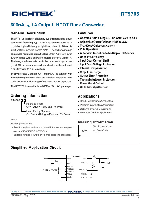
RT5705®DS5705-00 May 20171©Copyright 2017 Richtek Technology Corporation. All rights reserved. is a registered trademark of Richtek Technology Corporation.Simplified Application Circuit600nA I Q , 1A Output HCOT Buck ConverterGeneral DescriptionThe RT5705 is a high efficiency synchronous step-down converter featuring typ. 600nA quiescent current. It provides high efficiency at light load down to 10μA. Its input voltage range is from 2.2V to 5.5V and provides an adjustable regulated output voltage from 1.8V to 3.3V in 100mV steps while delivering output currents up to 1A.The integrated slew rate controlled load switch provides typ. 0.6Ω on-resistance and can distribute the selected output voltage to a sub-system.The Hysterestic Constant-On-Time (HCOT) operation with internal compensation allow the transient response to be optimized over a wide range of loads and output capacitors.The RT5705 is a available in WDFN-12AL 3x2 package.Features●Operates from a Single Li-ion Cell : 2.2V to 5.5V ●Adjustable Output Voltage : 1.8V to 3.3V ●Typ. 600nA Quiescent Current ●PFM Operation●Automatic Transition to No Ripple 100% Mode ●Up to 94% Efficiency●Input Over-Current Limit●Input Over-Voltage Protection ●Internal Compensation ●Output Discharge●Output Short Protection●Thermal shutdown Protection ●Power Good Output ●Up to 1A Output CurrentApplications●Hand-Held Devices Application ●Portable Information Application ●Battery Powered Equipment ●Wearable Devices ApplicationOrdering InformationNote :Richtek products are :❝ RoHS compliant and compatible with the current require-ments of IPC/JEDEC J-STD-020.❝ Suitable for use in SnPb or Pb-free soldering processes.Marking InformationRT5705G : Green (Halogen Free and Pb Free)00 : Product CodeW : Date CodeVRT57052DS5705-00 May 2017©Copyright 2017 Richtek Technology Corporation. All rights reserved. is a registered trademark of Richtek Technology Corporation.Functional Pin DescriptionPin Configuration(TOP VIEW)WDFN-12AL 3x2SW GND VSEL1VSEL2VIN EN VOUT VSEL3VSEL4CTRL PGOODLOADRT57053DS5705-00 May 2017©Copyright 2017 Richtek Technology Corporation. All rights reserved. is a registered trademark of Richtek Technology Corporation.Functional Block DiagramOperationThe RT5705 is a hysteretic constant on/off time (HCOT)switching buck converter, designed to an adjustable output voltage from an input supply voltage. The inductor current is regulated by a fast current regulator which is controlled by a voltage control loop. The voltage error amplifier getsits feedback input from the FB pin. The output voltage of the RT5705 is adjustable via SEL1 to SEL4 pins. When VIN is closed to VOUT , the device entering bypass mode with seamless technique and keep a minimum current ripple in the inductor to guarantee good performance.Absolute Maximum Ratings (Note 1)●Supply Input Voltage----------------------------------------------------------------------------------------------------0.3V to 5.5V●Power Dissipation, P D @ T A= 25°CWDFN-12AL 3x2--------------------------------------------------------------------------------------------------------- 3.17W●Package Thermal Resistance (Note 2)WDFN-12AL 3x2, θJA--------------------------------------------------------------------------------------------------- 31.5°C/W WDFN-12AL 3x2, θJC--------------------------------------------------------------------------------------------------- 6°C/W●Lead Temperature (Soldering, 10 sec.)----------------------------------------------------------------------------- 260°C●Junction T emperature Range------------------------------------------------------------------------------------------ 150°C●Storage T emperature Range------------------------------------------------------------------------------------------- −65°C to 150°C ●ESD Susceptibility (Note 3)HBM (Human Body Model)-------------------------------------------------------------------------------------------- 2kVRecommended Operating Conditions (Note 4)●Supply Input Voltage---------------------------------------------------------------------------------------------------- 2.7V to 4.5V●Junction T emperature Range------------------------------------------------------------------------------------------ −40°C to 125°C ●Ambient T emperature Range------------------------------------------------------------------------------------------ −40°C to 85°CElectrical Characteristics(V IN= 3.6V, C IN= 10μF, C OUT = 10μF, T A= 25°C unless otherwise specified)Note 1. Stresses beyond those listed “Absolute Maximum Ratings” may cause permanent damage to the device. These are stress ratings only, and functional operation of the device at these or any other conditions beyond those indicated in the operational sections of the specifications is not implied. Exposure to absolute maximum rating conditions may affect device reliability.Note 2.θJA is measured under natural convection (still air) at T A= 25°C with the component mounted on a high effective-thermal-conductivity four-layer test board on a JEDEC 51-7 thermal measurement standard. θJC is measured at the exposed pad of the package.Note 3. Devices are ESD sensitive. Handling precaution is recommended.Note 4. The device is not guaranteed to function outside its operating conditions.RT57056DS5705-00 May 2017 ©Copyright 2017 Richtek Technology Corporation. All rights reserved. is a registered trademark of Richtek Technology Corporation.Typical Application CircuitTable 1. Output Voltage SettingRT57057DS5705-00 May 2017©Copyright 2017 Richtek Technology Corporation. All rights reserved. is a registered trademark of Richtek Technology Corporation.Non-Switch Quiescent Current0.00.10.20.30.40.50.60.70.80.91.02.02.53.03.54.04.55.05.5Input Voltage (V)Q u i e s c e n t C u r r e n t ( A )Output Ripple Voltage010203040506070800.00.20.40.60.81.0Input Voltage (V)V O U T P P P e a k t o P e a k O u t p u t R i p p l e (m V )Output Ripple Voltage 051015202530354045500.00.20.40.60.81.0Input Voltage(V)V O U T P P P e a k t o P e a k O u t p u t R i p p l e (m V )Switch Frequency0.00.20.40.60.81.01.21.41.61.82.00.00.20.40.60.81.0Output Current (A)F r e q u e n c y (M H Z )Switch Frequency0.00.20.40.60.81.01.21.41.61.82.00.00.20.40.60.81.0Output Current (A)F r e q u e n c y (M H Z )Typical Operating CharacteristicsShutdown Current0.000.050.100.150.202.02.53.03.54.04.55.05.5Input Voltage (V)Q u i e s c e n t C u r r e n t ( A )μμRT57058DS5705-00 May 2017 ©Copyright 2017 Richtek Technology Corporation. All rights reserved. is a registered trademark of Richtek Technology Corporation.Line Regulation3.203.253.303.353.403.453.33.84.34.85.35.8Input Voltage (V)O u t p u t V o l t a g e (V )Line Regulation1.771.791.811.831.851.872.22.73.23.74.24.75.2 5.76.2Input Voltage (V)O u t p u t V o l t a g e (V )Line Reg Pass Through2.002.052.102.152.202.252.302.352.402.202.252.302.352.402.452.50Input Voltage (V)O u t p u t V o l t a g e (V )Efficiency1020304050607080901000.0000010.00010.011I OUT (A)E f f i c i e n c y (%)Line Reg Pass Through2.42.52.62.72.82.93.02.42.52.62.72.82.9Input Voltage (V)O u t p u t V o l t a g e (V )Line Reg Pass Through3.23.33.43.53.63.73.8Input Voltage (V)O u t p u t V o l t a g e (V )RT57059DS5705-00 May 2017©Copyright 2017 Richtek Technology Corporation. All rights reserved. is a registered trademark of Richtek Technology Corporation.V OUT Ripple VoltageTime (4ms/Div)V IN = 3.6V, V OUT = 1.8V, I OUT = 10μA, Ctrl = LV OUT(20mV/Div)LX (2V/Div)Time (40μs/Div)V IN = 4.5V, V OUT = 3.5V,I OUT = 0A to 2ATime (1μs/Div)I LX(200mA/Div)V OUT (20mV/Div)LX (2V/Div)I LX(200mA/Div)V IN = 3.6V, V OUT = 1.8V, I OUT = 10mA, Ctrl = LV OUT(20mV/Div)LX (2V/Div)I LX(200mA/Div)V IN = 3.6V , V OUT = 1.8V, I OUT = 500mA, Ctrl = LEfficiency0.0000010.00010.011I OUT (A)Load Regulation1.701.751.801.851.901.950.0000010.00010.011I OUT (A)O u t p u t V o l t a g e (V )Load Regulation0.0000010.00010.011I OUT (A)RT570510DS5705-00 May 2017 ©Copyright 2017 Richtek Technology Corporation. All rights reserved. is a registered trademark of Richtek Technology Corporation.V OUT Ripple VoltageTime (1μs/Div)V OUT(20mV/Div)LX (2V/Div)I LX(200mA/Div)V IN = 3.6V, V OUT = 1.8V, I OUT= 1A, Ctrl = LTime (5ms/Div)V OUT (20mV/Div)LX (4V/Div)I LX(500mA/Div)V IN = 3.6V, V OUT = 1.8V ,I OUT = 0A to 2A, Ctrl = LLoad TransientTime (50μs/Div)V OUT(50mV/Div)I OUT(100mA/Div)Load TransientTime (50μs/Div)Time (50μs/Div)Time (50μs/Div)Load_V (50mV/Div)Load_I (50mA/Div)I OUT(200mA/D iv)V IN = 3.6V, V OUT = 1.8V, t R = t F = 1μs,I OUT = 0mA to 150mA, Ctrl = LV OUT (50mV/Div)I OUT(200mA/Div)V IN = 3.6V , V OUT = 1.8V , t R = t F = 1μs,I OUT = 0mA to 300mA, Ctrl = LV OUT(100mV/Div)I OUT(500mA/Div)V IN = 3.6V, V OUT = 1.8V , t R = t F = 1μs,I OUT = 0A to 1A, Ctrl = LV OUT (50mV/Div)V IN = 3.6V , V OUT = 1.8V , t R = t F = 1μs,I OUT = 0mA to 100mA, Ctrl = HDS5705-00 May 2017©Copyright 2017 Richtek Technology Corporation. All rights reserved. is a registered trademark of Richtek Technology Corporation.Time (400μs/Div)V OUT(500mV/Div)PG (2V/Div)I LX(200mA/Div)V IN = 3.6V , V OUT = 1.8V ,I OUT= 0A, Ctrl = LTime (400μs/Div)Power Off ENTime (100μs/Div)V IN = 3.6V, V OUT = 1.8V,I OUT = 0A, Ctrl = LPower Off ENTime (20μs/Div)V IN = 3.6V, V OUT = 1.8V ,I OUT= 1A, Ctrl = LTime (500μs/Div)Load (500mV/Div)I LX(200mA/Div)V IN = 3.6V , V OUT = 1.8V ,I OUT = 0A, I OUT_LSW = 0A,Ctrl = HTime (500μs/Div)V EN (2V/Div)V OUT(500mV/Div)PG (2V/Div)I LX(500mA/Div)V EN (2V/Div)V IN = 3.6V, V OUT = 1.8V,I OUT = 1A, Ctrl = LV OUT(500mV/Div)PG (2V/Div)I LX(200mA/Div)V EN (2V/Div)V OUT(500mV/Div)PG (2V/Div)I LX(500mA/Div)V EN (2V/Div)V OUT(500mV/Div)PG (2V/Div)V IN = 3.6V, V OUT = 1.8V,I OUT = 1A, I OUT_LSW = 0A,Ctrl = HLoad (500mV/Div)I LX(500mA/Div)V OUT(500mV/Div)PG (2V/Div)©Copyright 2017 Richtek Technology Corporation. All rights reserved. is a registered trademark of Richtek Technology Corporation.Time (100μs/Div)Time (10μs/Div)Dynamic VSELTime (600μs/Div)VSEL (2V/Div)I LX (1A/Div)V IN = 3.6V, V OUT = 1.8V to 3.3V ,I OUT = 5mA, Ctrl = LInput Voltage Ramp Up/DownTime (20ms/Div)I LX(200mA/Div)V IN = 0V to 5V,V OUT = 1.8V,I OUT = 5mA, Ctrl = LTime (20ms/Div)Load (500mV/Div)I LX(100mA/Div)V OUT(500mV/Div)PG (2V/Div)V IN = 3.6V, V OUT = 1.8V ,I OUT = 0A, I OUT_LSW = 0A,Ctrl = HLoad (500mV/Div)I LX(100mA/Div)V OUT(500mV/Div)PG (2V/Div)V IN = 3.6V, V OUT = 1.8V ,I OUT = 1A, I OUT_LSW = 0A,Ctrl = HPG (1V/Div)V OUT(500mV/Div)V EN (1V/Div)V IN = 0V to 5V,V OUT = 3.3V,I OUT = 5mA, Ctrl = LV OUT (1V/Div)I LX(200mA/Div)V EN (1V/Div)V OUT(500mV/Div)DS5705-00 May 2017©Copyright 2017 Richtek Technology Corporation. All rights reserved. is a registered trademark of Richtek Technology Corporation.Application InformationThe RT5705 is a synchronous low voltage step-down converter that can support the input voltage range from 2.2V to 5.5V and the output current can be up to 1A.Internal compensation are integrated to minimize external component count. Protection features include over current protection, under voltage protection and over temperature protection.UVLO ProtectionTo protect the chip from operating at insufficient supply voltage, the UVLO is needed. When the input voltage of VIN is lower than the UVLO falling threshold voltage, the device will be lockout.EnableThe device can be enabled or disenabled by the EN pin.When the EN pin is higher than the threshold of logic high, the device starts operation with soft-start. Once the EN pin is set at low, the device will be shut down. In shutdown mode, the converter stops switching, internal control circuitry is turned off, and the load is disconnected from the input. This also means that the output voltage can drop below the input voltage during shutdown.Output Voltage SettingThe RT5705 doesn’t require an external resistor divider to program the output voltage. The device by the pins VSEL 1-4. The RT5705 supports an output voltage range of 1.8V to 3.3V in 100mV steps. The output voltage can be changed during operation and supports a simple dynamic output voltage scaling, shown .The output voltage is programmed according to table Table 1.Power GoodWhen the output voltage is higher than PG rising threshold,the PG flag is High.CTRL with Load SwitchThe CTRL pin set to high, the LOAD pin is connected to the VOUT pin via an load switch and can power up an additional, provide sub-system used .If CTRL pin is pulled to GND, the LOAD pin is disconnected from the VOUT pin and internally connected to GND by an internal discharge switch.Inductor SelectionThe recommended power inductor is 2.2μH with over 1.6A saturation current rating. In applications, need to select an inductor with the low DCR to provide good performance and efficiency.C IN and C OUT SelectionThe input capacitance, C IN , is needed to filter the trapezoidal current at the source of the top MOSFET . To prevent large ripple voltage, a low ESR input capacitor sized for the maximum RMS current should be used. RMS current is given by :This formula has a maximum at V IN = 2V OUT , where I RMS =I OUT /2. This simple worst-case condition is commonly used for design because even significant deviations do not offer much relief. Choose a capacitor rated at a higher temperature than required.Several capacitors may also be paralleled to meet size or height requirements in the design.The selection of C OUT is determined by the Effective Series Resistance (ESR) that is required to minimize voltage ripple and load step transients, as well as the amount of bulk capacitance that is necessary to ensure that the control loop is stable. Loop stability can be checked by viewing the load transient response as described in a later section.The output ripple, ΔV OUT, is determined by :⨯OUT RMS OUT(MAX)IN V I = I 1V ⎡⎤∆≤∆⎢⎥⨯⨯⎣⎦OUT L OUT 1V I ESR + 8f C©Copyright 2017 Richtek Technology Corporation. All rights reserved. is a registered trademark of Richtek Technology Corporation.Thermal ConsiderationsThe junction temperature should never exceed the absolute maximum junction temperature T J(MAX), listed under Absolute Maximum Ratings, to avoid permanent damage to the device. The maximum allowable power dissipation depends on the thermal resistance of the IC package, the PCB layout, the rate of surrounding airflow,and the difference between the junction and ambient temperatures. The maximum power dissipation can be calculated using the following formula :P D(MAX) = (T J(MAX) − T A ) / θJAwhere T J(MAX) is the maximum junction temperature, T A is the ambient temperature, and θJA is the junction-to-ambient thermal resistance.For continuous operation, the maximum operating junction temperature indicated under Recommended Operating Conditions is 125°C. The junction-to-ambient thermal resistance, θJA , is highly package dependent. For a WDFN-12AL 3x2 package, the thermal resistance, θJA , is 31.5°C/W on a standard JEDEC 51-7 high effective-thermal-conductivity four-layer test board. The maximum power dissipation at T A = 25°C can be calculated as below :P D(MAX) = (125°C − 25°C) / (31.5°C/W) = 3.17W for a WDFN-12AL 3x2 package.The maximum power dissipation depends on the operating ambient temperature for the fixed T J(MAX) and the thermal resistance, θJA . The derating curves in Figure 1 allows the designer to see the effect of rising ambient temperature on the maximum power dissipation.Figure 1. Derating Curve of Maximum Power Dissipation0.00.40.81.21.62.02.42.83.23.64.0255075100125Ambient Temperature (°C)M a x i m u m P o w e r D i s s i p a t i o n (W )Layout ConsiderationsSome PCB layout guidelines for optimal performance of the RT5705 list as following.Following figure shows the real PCB layout considerations and it is based on the real component size whose unit is millimeter (mm).❝The input capacitor should be placed as closed as possible to PVIN pin for good filtering.❝The high current path should be made as short and wide as possible.❝The inductor should be placed as close to LX1 and LX2pin for reducing EMI.❝The output capacitor should be placed as closed as PGND pin to ground plane to reduce noise coupling.DS5705-00 May 2017©Copyright 2017 Richtek Technology Corporation. All rights reserved. is a registered trademark of Richtek Technology Corporation.Figure 2. PCB Layout GuideW-Type 12AL DF N 3x2 PackageRichtek Technology Corporation14F, No. 8, Tai Yuen 1st Street, Chupei CityHsinchu, Taiwan, R.O.C.Tel: (8863)5526789Richtek products are sold by description only. Richtek reserves the right to change the circuitry and/or specifications without notice at any time. Customers should obtain the latest relevant information and data sheets before placing orders and should verify that such information is current and complete. Richtek cannot assume responsibility for use of any circuitry other than circuitry entirely embodied in a Richtek product. Information furnished by Richtek is believed to be accurate and reliable. However, no responsibility is assumed by Richtek or its subsidiaries for its use; nor for any infringements of patents or other rights of third parties which may result from its use. No license is granted by implication or otherwise under any patent or patent rights of Richtek or its subsidiaries.。
Hitachi 硬盘产品说明书

CONTINUED > 2.5-Inch HDD pg 2CONTINUED > 2.5-Inch SSD pg 3New Seagate Model Number Key, EnterpriseST 500 NM 123 1BRANDCAPACITYSEGMENTATTRIBUTESGENERATION2 letters ST = Seagate MX = Maxtor2 to 4 digits 500 = 500GB 1000 = 1000GBCapacities >9999GB:10 = 10TB 15 = 15TB2 lettersMM = Mission-Critical, 2.5-Inch, 10K MX = Mission-Critical, 2.5-Inch, 15K NM = Nearline, 3.5-Inch NX = Nearline, 2.5-Inch FM = SSD Mainstream FX = SSD Performance3 digits, non-intelligentVaries as needed, for example:Interface RPM Cache SED1 digit, intelligent 1 = 1st Generation2 = 2nd Generation3 = 3rd GenerationSeagate Partner Program MembersVisit the Sales Tools section to access the latest product roadmap, end-of-life schedule and product information. DistributorsEMEA SPP Support00-800-6890-8282US Sales Support1-800-SEAGATE or 1-405-324-4700Visit for more information or call 1-800-SEAGATE (1-800-732-4283) © 2012 Seagate Technology LLC. All rights reserved. Printed in USA. Seagate, Seagate Technology and the Wave logo are registered trademarksof Seagate Technology LLC in the United States and/or other countries. Cheetah, Constellation.2, Pulsar, Pulsar.2 and Savvio are either trademarks or registered trademarks of Seagate Technology LLC or one of its affiliated companies in the United States and/or other countries. The FIPS logo is a certification mark of NIST, which does not imply product endorsement by NIST, the U.S., or Canadian governments. All other trademarks or registered trademarks are the property of their respective owners. When referring to drive capacity, one gigabyte, or GB, equals one billion bytes and one terabyte, or TB, equals one trillion bytes. Your computer’s operating system may use a different standard of measurement and report a lower capacity. In addition, some of the listed capacity is used for formatting and other functions, and thus will not be available for data storage. Actual data rates may vary depending on operating environment and other factors. The export or re-export of hardware or software containing encryption may be regulated by the U.S. Department of Commerce, Bureau of Industry and Security (for more information, visit ). Seagate reserves the right to change, without notice, product offerings or specifications. QR501.14-1202US, February 20122 Self-Encrypting Drives (SED) and FIPS 140-2 Validated drives are not available in all models or countries. May require TCG-compliant host or controller support.3 See FIPS 140-2 Level 2 Certificate at /groups/STM/cmvp/documents/140-1/1401val2010.htm#12994 Data provided is based on format at 512 bytes.View a brief training presentation on how our model number format has changed at /seagate/ModelNumber。
硬件说明

主板代工工厂编码,让您知道您的主板真实厂家主板代工工厂编码,让您知道您的主板真实厂家D33002 IBM-Hitachi(日立)工厂,台式硬盘、移动硬盘制造。
D33004 FOXCONN台湾工厂,从事各种板卡类制造。
D33005 ASUS华硕电脑,板卡,笔记本电脑制造。
D33006 GIGABYTE工厂,板卡制造。
D33007 FIC大众台湾工厂,板卡制造。
D33008 MSI微星科技,板卡制造。
D33010 HIS金星合资工厂,晶片制造。
D33011 PowerColor-TUL工厂,板卡制造。
(原撼讯)D33014 WD泰国工厂(原Fujistu工厂),台式硬盘、移动硬盘制造D33015 WD工厂,台式硬盘、移动硬盘制造D33017 Hitachi-LG光学工厂,光磁驱动器制造。
D33019 MAXTOR新加坡工厂,台式硬盘、移动硬盘制造D33027 Seagate希捷科技,台式硬盘、移动硬盘制造D33032 Shuttle浩鑫工厂,板卡、XPC制造,D41039 Aopen台湾工厂,板卡,机箱,电源,光磁产品制造D33058 Chantech承启工厂,板卡制造。
D33064 DFI友通科技,板卡制造D33068 Abit罗礼工厂,板卡制造。
D33071 MITEC工厂,笔记本电脑,光磁产品制造。
D33075 Sparkle旌宇工厂,板卡制造。
D33080 海韵科技D33083 GIGABYTE原QDI合资工厂,板卡制造D33088 Galaxy嘉威FOXCONN合资工厂,板卡制造D33221 EPOX大陆工厂,板卡,蓝牙适配器制造D33282 Albatron青云国际,板卡制造D33171 ASMART台湾工厂D31010 ASUS台湾老工厂,板卡制造D33271 FOXCONN马来西亚工厂,板卡制造D33A27 YUAN聪泰,板卡制造D43136 金星科技D33529 Super FlowerD33108 七盟电子,电源、机箱制造D33373 原IBM-易拓工厂,台式硬盘、移动硬盘制造D41126 Logitech苏州工厂,外设制造D33221 EPOX大陆工厂,板卡制造D33475 三星韩国工厂,板卡,颗粒制造D43001 全汉科技(为Nexus等大厂做ODM),电源制造D33567 康舒电子(为IBM、HP、DELL、酷冷至尊等做OE/DM)外设制造D33081 耀越宏展科技 TT,外设制造。
产品介绍Productdescription

产品介绍Productdescription使⽤清洁燃⽓的低温燃烧器Low temperature burner for use with clean fuel gases 在30%的过剩空⽓下,氮氧化物排放只有个位数Single digit NOx emissions at 30% excess air 低过剩空⽓要求下,⾼效率High efficiency with low excess air requirements 麦克森XPO?低温燃烧器,适⽤于间接液体加热应⽤,包含:MAXON XPO? burners are low temperature burners for use in liquid backed applications, including:XPO?燃烧器要求很低的过剩空⽓,所以运⾏效率⾼。
其设计旨在更⽅便地对现有的液体加热应⽤进⾏改造。
XPO? burners provide high efficiency operation with low excess air requirements. They are designed for ease of retrofitting into existing liquid backed applications.XPO?燃烧器有两种基础版本可供选择:XPO? burners are available in two basic versions: 配备整体风机的⼀体式燃烧器(PB )版本Packaged (PB) with integral combustion air blower为扩⼤燃烧能⼒,使⽤外部⽓源的外部风机(EB )版本External blower (EB) for use with an externalcombustion air source for extended capacities⽆论是⼀体式版本(PB )还是外部风机版本(EB ),其风管长度均有两种不同选择:610毫⽶或1220毫⽶。
Seagate FireCuda 530 SSD 说明书

最佳应用高性能游戏台式机创意专业人士系统品资料势不可挡。
出色性能和超高耐用性 - Seagate ® FireCuda ® 530 重新确立速度定义,高达 7,300MB/秒的速度发挥出 PCIe ® Gen4 的全部潜力。
传输速率高达PCIe Gen3 的 2 倍,FireCuda 530 可在持续高强度使用下,保持可靠性能。
PCIe Gen4 的速度尽在掌间。
主要优势速度为王。
Seagate FireCuda 530 在 SSD 产品系列中处于领先位置,提供出色性能、先进组件以及超高耐用性。
性能优异。
利用高达 7,300MB/秒的出色 PCIe Gen4 速度,尽享下一代游戏和应用。
史上速度最快的FireCuda 硬盘专为持续、专业级游戏和内容创作加速而打造,传输速度高达 PCIe Gen3 NVMe SSD 的 2 倍,SATA SSD 的 12 倍。
最新技术。
FireCuda 530 采用经 Seagate 验证的 E18 控制器和最新的 3D TLC NAND ,提供出色的速度和耐用性,助您突破机器的极限。
经久耐用。
专为高强度使用设计,坚固耐用,历久弥新 - 高达 5,100TB TBW 意味着您可以在五年内每天写入和删除 70% 的硬盘容量。
容量可观。
高达 4TB 的容量,轻松应对图形密集型游戏和大文件,让您的游戏库和创意内容触手可及。
游戏和创作。
利用高达 7,300MB/秒的惊人传输速度,以及出色的耐用性和容量,更快、更流畅地运行内容创作应用。
Rescue 服务。
随附三年 Rescue Data Recovery Services 数据救援服务1,提供行业领先的 95% 成功率,可防止意外数据丢失,让您高枕无忧。
1 Rescue Data recovery Services 数据救援服务供应国家/地区视具体情况而定。
规格4TB2TB1TB500GB标准型号ZP4000GM30013ZP2000GM30013ZP1000GM30013ZP500GM30013接口PCIe® Gen4 ×4 NVMe 1.4PCIe Gen4 ×4 NVMe 1.4PCIe Gen4 ×4 NVMe 1.4PCIe Gen4 ×4 NVMe 1.4NAND 闪存3D TLC3D TLC3D TLC3D TLC外形规格M.2 2280-D2M.2 2280-D2M.2 2280-S2M.2 2280-S2性能顺序读取(最大,MB/秒),128KB27,3007,3007,3007,000顺序写入(最大,MB/秒),128KB26,9006,9006,0003,000随机读取(最大,IOPS),4KB QD32 T821,000,0001,000,000800,000400,000随机写入(最大,IOPS),4KB QD32 T821,000,0001,000,0001,000,000700,000耐用性/可靠性总写入字节数 (TB)5,1002,5501,275640平均故障间隔时间(MTBF,小时)1,800,0001,800,0001,800,0001,800,000Rescue Data Recovery Services3333(years)3质保年限5555电源管理运行功耗,平均(瓦)8.48 6.5 5.8闲置功耗 PS3,平均(毫瓦)25241614低功率 L1.2 模式 (mW)<5<5<5<5环境运行时内部温度 (°C)0°C – 70°C0°C – 70°C0°C – 70°C0°C – 70°C非运行时温度 (°C)-40°C – 85°C-40°C – 85°C-40°C – 85°C-40°C – 85°C非运行时抗冲击性:0.5 毫秒 (G)1,5001,5001,5001,500特殊特性TRIM是是是是S.M.A.R.T.是是是是无卤素是是是是符合 RoHS是是是是物理规格最大长度(毫米/英寸)80.15 毫米/3.156 英寸80.15 毫米/3.156 英寸80.15 毫米/3.156 英寸80.15 毫米/3.156 英寸最大宽度(毫米/英寸)22.15 毫米/0.872 英寸22.15 毫米/0.872 英寸22.15 毫米/0.866 英寸22.15 毫米/0.872 英寸最大高度(毫米/英寸) 3.58 毫米/0.141 英寸 3.58 毫米/0.141 英寸 2.23 毫米/0.088 英寸 2.23 毫米/0.088 英寸重量(克/磅)10.6 克/0.023 磅10 克/0.022 磅8.1 克/0.017 磅7.7 克/0.016 磅1 从新格式化的硬盘中获得全新开箱 (FOB) 性能。
ICS570中文资料
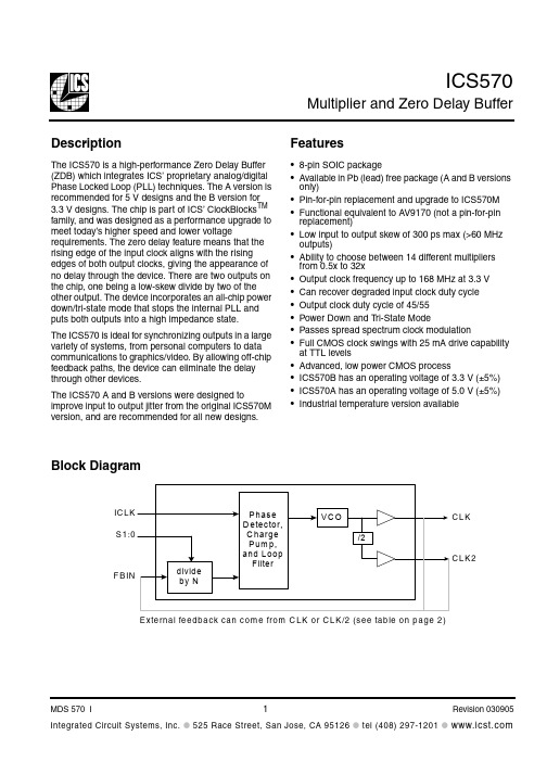
ICS570 Multiplier and Zero Delay BufferDescriptionThe ICS570 is a high-performance Zero Delay Buffer (ZDB) which integrates ICS’ proprietary analog/digital Phase Locked Loop (PLL) techniques. The A version is recommended for 5 V designs and the B version for 3.3 V designs. The chip is part of ICS’ ClockBlocks TM family, and was designed as a performance upgrade to meet today’s higher speed and lower voltage requirements. The zero delay feature means that the rising edge of the input clock aligns with the rising edges of both output clocks, giving the appearance of no delay through the device. There are two outputs on the chip, one being a low-skew divide by two of the other output. The device incorporates an all-chip power down/tri-state mode that stops the internal PLL and puts both outputs into a high impedance state.The ICS570 is ideal for synchronizing outputs in a large variety of systems, from personal computers to data communications to graphics/video. By allowing off-chip feedback paths, the device can eliminate the delay through other devices.The ICS570 A and B versions were designed to improve input to output jitter from the original ICS570M version, and are recommended for all new designs.Features•8-pin SOIC package•Available in Pb (lead) free package (A and B versions only)•Pin-for-pin replacement and upgrade to ICS570M •Functional equivalent to AV9170 (not a pin-for-pin replacement)•Low input to output skew of 300 ps max (>60 MHz outputs)•Ability to choose between 14 different multipliers from 0.5x to 32x•Output clock frequency up to 168 MHz at 3.3 V •Can recover degraded input clock duty cycle •Output clock duty cycle of 45/55•Power Down and T ri-State Mode•Passes spread spectrum clock modulation•Full CMOS clock swings with 25 mA drive capability at TTL levels•Advanced, low power CMOS process•ICS570B has an operating voltage of 3.3 V (±5%)•ICS570A has an operating voltage of 5.0 V (±5%)•Industrial temperature version availableBlock DiagramMultiplier and Zero Delay BufferPin AssignmentClock Multiplier Decoding Table(Multiplies Input clock by amount shown)0 = connect directly to groundM = leave unconnected (self-biases to VDD/2)1 = connect directly to VDD*Input range with CLK feedback is double that for CLK/2Pin DescriptionsS1S0FBIN from CLKFBIN from CLK/2ICS570B (3.3 V)ICS570A (5.0 V)CLK CLK2CLK CLK2ICLK Input Range FB from CLK/2*ICLK Input Range FB from CLK/2*#1 #6pin #7pin #8pin #7pin #800Power Down and Tri-State--0M x3x1.5x6x3 3.75 to 28 2.5 to 2501x4x2x8x4 2.75 to 19 2.5 to 19M 0x8x4x16x8 2.5 to 9.5 2.5 to 9.5M M x6x3x12x6 2.5 to 12.5 2.5 to 12.5M 1x10x5x20x10 2.5 to 7.5 2.5 to 7.510x1/2x2x111 to 75 5 to 751Mx16x8x32x162.5 to 5 2.5 to 511x2x1x4x2 5.5 to 37.52.5 to 37.5Pin NumberPin NamePin TypePin Description1S1Input Select 1 for output clock. Connect to GND, VDD, or float per decoding table above.2VDD Power Connect to +3.3 V (ICS570B). Connect to +5.0 V (ICS570A).3GND Power Connect to ground.4ICLK Input Reference clock input.5FBIN Input Feedback clock input.6S0Input Select 0 for output clock. Connect to GND, VDD, or float per decoding table above.7CLK Output Clock output per table above.8CLK/2OutputClock output per table above. Low skew divide by two of pin 7 clock.Multiplier and Zero Delay BufferExternal ComponentsThe ICS570 requires a 0.01µF decoupling capacitor to be connected between VDD and GND. It must be connected close to the part to minimize lead inductance. No external power supply filtering is required for this device. A 33Ω series terminating resistor can be used next to each output pin.Recommended CircuitUsing CLK as the feedback will always result in synchronized rising edges between ICLK and CLK.However, the CLK/2 could be a falling edge compared with ICLK. ICS recommends using CLK/2 feedback whenever possible. This will synchronize the rising edges of all three clocks.Multiplier and Zero Delay BufferClock Period Jitter Tables (ICS570A)All jitter values are considered typical measured at 25°C with 27Ω termination resistor and 15 pF loads on both CLK and CLK/2. The feedback is from CLK/2 to FBIN. Note that if an output is unused, it should be left unconnected to improve output jitter on the active output clocks.Absolute and One Sigma Jitter (ps)Absolute and One Sigma Jitter (ps)Absolute and One Sigma Jitter (ps)CLK = 50MCLK/2 = 25MS1S0CLKIN (MHz)MultiplierP to P 1 sigma MultiplierP to P 1 sigma 0M 8.3336x ±115803x ±652001 6.258x ±115804x ±6020M 0 3.12516x ±120808x ±5520M M 4.16712x ±120906x ±6020M 1 2.520x ±1208010x ±602010252x ±120701x ±55201M 1.562532x ±1208016x ±50201112.54x±120802x±5520CLK = 100MCLK/2 = 50MS1S0CLKIN (MHz)MultiplierP to P 1 sigma MultiplierP to P 1 sigma 0M 16.6676x ±1351003x ±55200112.58x ±1401004x ±5020M 0 6.2516x ±1401108x ±5520M M 8.33312x ±1401106x ±5520M 1520x ±13510010x ±502010502x ±120901x ±50201M 3.12532x ±13510016x ±552011254x±130902x±6520CLK = 150MCLK/2 = 75MS1S0CLKIN (MHz)MultiplierP to P 1 sigma MultiplierP to P 1 sigma 0M 256x ±1601203x ±55200118.3758x ±1651204x ±5520M 09.37516x ±1701208x ±5020M M 12.512x ±1601206x ±5520M 17.520x ±16012010x ±552010752x ±1551101x ±55201M 4.687532x ±16512016x ±55201137.54x±1601102x±5020Multiplier and Zero Delay BufferClock Period Jitter Tables (ICS570B)All jitter values are considered typical measured at 25°C with 27Ω termination resistor and 15 pF loads on both CLK and CLK/2. The feedback is from CLK/2 to FBIN. Note that if an output is unused, it should be left unconnected to improve output jitter on the active output clocks.Absolute and One Sigma Jitter (ps)Absolute and One Sigma Jitter (ps)Absolute and One Sigma Jitter (ps)CLK = 50MCLK/2 = 25MS1S0CLKIN (MHz)MultiplierP to P 1 sigma MultiplierP to P 1 sigma 0M 8.3336x ±110803x ±552001 6.258x ±125904x ±5020M 0 3.12516x ±130908x ±5520M M 4.16712x ±120906x ±5520M 1 2.520x ±1159010x ±552010252x ±130501x ±55201M 1.562532x ±1209016x ±55201112.54x±120602x±5520CLK = 100MCLK/2 = 50MS1S0CLKIN (MHz)MultiplierP to P 1 sigma MultiplierP to P 1 sigma 0M 16.6676x ±100703x ±45200112.58x ±100704x ±4520M 0 6.2516x ±110808x ±4520M M 8.33312x ±100706x ±4520M 1520x ±1057010x ±402010502x ±90601x ±40201M 3.12532x ±957016x ±452011254x±105702x±6020CLK = 150MCLK/2 = 75MS1S0CLKIN (MHz)MultiplierP to P 1 sigma MultiplierP to P 1 sigma 0M 256x ±115703x ±50200118.3758x ±120804x ±5020M 09.37516x ±130908x ±5020M M 12.512x ±130906x ±4520M 17.520x ±1309010x ±452010752x ±115901x ±45201M 4.687532x ±1309016x ±50201137.54x±110702x±6020Multiplier and Zero Delay BufferAbsolute Maximum RatingsStresses above the ratings listed below can cause permanent damage to the ICS570. These ratings, which are standard values for ICS commercially rated parts, are stress ratings only. Functional operation of the device at these or any other conditions above those indicated in the operational sections of thespecifications is not implied. Exposure to absolute maximum rating conditions for extended periods can affect product reliability. Electrical parameters are guaranteed only over the recommended operating temperature range.Recommended Operation ConditionsDC Electrical CharacteristicsUnless stated otherwise, VDD = 3.3 V ±5%, Ambient Temperature -40 to +85°CItemRatingSupply Voltage, VDD 7 VAll Inputs and Outputs-0.5 V to VDD+0.5 V Ambient Operating Temperature, Commercial version 0 to +70°C Ambient Operating Temperature, Industrial version -40 to +85°C Storage Temperature -65 to +150°C Junction Temperature 125°C Soldering Temperature260°CParameterMin.Typ.Max.UnitsAmbient Operating Temperature, Commercial version 070°C Ambient Operating Temperature, Industrial version -40+85°C Power Supply Voltage (measured in respect to GND)+3.15+3.3+3.45VParameterSymbol ConditionsMin.Typ.Max.UnitsOperating Voltage VDD ICS570B 3.15 3.45V ICS570A 4.755.25Operating CurrentIDDICS570B3.3 V, 50M input, S1:0 = 1116mAICS570A5.0 V, 50M input, S1:0 = 1125mAInput High Voltage V IH ICLK, FBIN 2V Input Low Voltage V IL ICLK, FBIN 0.8V Input High Voltage V IH S0, S1VDD-0.5V Input Low Voltage (mid-level)V IMS0, S1VDD/2VMultiplier and Zero Delay BufferAC Electrical CharacteristicsUnless stated otherwise, VDD = 3.3 V ±5%, Ambient Temperature -40 to +85°CNote 1: Assumes clocks with same rise time, measured from rising edges at VDD/2Note 2: Measured with 27Ω terminating resistor and 15 pF loadsThermal CharacteristicsInput Low VoltageV IL S0, S10.5V Output High Voltage (CMOS High)V OH I OH = -4 mA VDD-0.4V Output High Voltage V OH I OH = -12 mA 2.4VOutput Low Voltage V OL I OL = 12mA 0.4V Short Circuit Current I OS Each output ±100mA Input CapacitanceC INS0, S15pFParameterSymbol ConditionsMin.Typ.Max.UnitsInput Frequency, ICLK FBIN from CLK/2See table on page 2Output Clock Frequency CLK 10168MHz Output to Output Skew ICS570B 100175ps Output to Output Skew ICS570A 100200ps Input to Output Jitter40 - 150 MHz 100-250psInput Skew, ICS570BICLK to FBIN,CLK>30MHz, Note 1-300300ps ICLK to FBIN,CLK<10MHz, Note 1-600600ps Input Skew, ICS570A ICLK to FBINCLK>30MHz, Note 1-11ns ICLK to FBIN,CLK<10MHz, Note 1-1.51.5ns Output Clock Rise Time 0.8 to 2.0V, Note 20.75ns Output Clock Fall Time 2.0 to 0.8V, Note 20.75nsOutput Clock Duty Cycleat VDD/24549 - 5155%ParameterSymbol ConditionsMin.Typ.Max.UnitsParameterSymbolConditionsMin.Typ.Max.UnitsThermal Resistance Junction to AmbientθJA Still air 150°C/W θJA 1 m/s air flow 140°C/W θJA 3 m/s air flow120°C/W Thermal Resistance Junction to CaseθJC40°C/WPackage dimensions are kept current with JEDEC Publication No. 95Multiplier and Zero Delay BufferOrdering Information“LF” denotes Pb (lead) free package.While the information presented herein has been checked for both accuracy and reliability, Integrated Circuit Systems (ICS) assumes no responsibility for either its use or for the infringement of any patents or other rights of third parties, which would result from its use. No other circuits, patents, or licenses are implied. This product is intended for use in normal commercial applications. Any other applications such as those requiring extended temperature range, high reliability, or other extraordinary environmental requirements are not recommended without additional processing by ICS. ICS reserves the right to change any circuitry or specifications without notice. ICS does not authorize or warrant any ICS product for use in life support devices or critical medical instruments.Part / Order NumberMarkingShipping PackagingPackageTemperatureICS570A ICS570A T ubes 8-pin SOIC 0 to +70° C ICS570A T ICS570A T ape and Reel8-pin SOIC 0 to +70° C ICS570AI ICS570AI T ubes 8-pin SOIC -40 to 85° C ICS570AIT ICS570AI T ape and Reel8-pin SOIC -40 to 85° C ICS570AILF 570AILF T ubes 8-pin SOIC -40 to 85° C ICS570AILFT 570AILF T ape and Reel8-pin SOIC -40 to 85° C ICS570ALF 570ALF T ubes 8-pin SOIC 0 to +70° C ICS570ALFT 570ALF T ape and Reel8-pin SOIC 0 to +70° C ICS570B ICS570B T ubes 8-pin SOIC 0 to +70° C ICS570BT ICS570B T ape and Reel8-pin SOIC 0 to +70° C ICS570BLF ICS570BL T ubes 8-pin SOIC 0 to +70° C ICS570BLFT ICS570BL T ape and Reel8-pin SOIC 0 to +70° C ICS570BI ICS570BI T ubes 8-pin SOIC -40 to 85° C ICS570BIT ICS570BI T ape and Reel8-pin SOIC -40 to 85° C ICS570BILF 570BILF T ubes 8-pin SOIC -40 to 85° C ICS570BILFT 570BILF T ape and Reel8-pin SOIC -40 to 85° C ICS570M ICS570M T ubes 8-pin SOIC 0 to +70° C ICS570MT ICS570M T ape and Reel8-pin SOIC 0 to +70° C ICS570MI ICS570MI T ubes 8-pin SOIC -40 to 85° C ICS570MITICS570MIT ape and Reel8-pin SOIC-40 to 85° C。
VERSATIS 570 數位式無線電話機 使用說明書

VERSATIS 570數位式無線電話機使用說明書為充分發揮本機功能,在您使用前請詳細閱讀本說明書,並妥善保存,作為日後參考(一)目錄 .............................. 1(二)本機特點 ........................ 2(三)安裝方法 ........................ 2(四)外型及各部位名稱 ............ 3(五)使用說明 ........................ 4 接聽電話 ........................ 4 撥打電話 ........................ 4 預覽撥號 ........................ 4 靜音功能 ........................ 5 免持對講功能 .................. 5 呼叫功能 ........................ 5 內線對講 ........................ 5 關閉手機電源 .................. 5 電話簿儲存功能 ............... 6 座機鈴聲音量設定 ............ 7 座機鈴聲音樂選擇 ............ 7 選擇座機 ........................ 7 刪除手機 ........................ 8 更改密碼 ........................ 8 開/關-外線來鈴的優先順序.8 設定外線來鈴的優先順序 ... 9 撥號方式的設定 ............... 9 R鍵時間設定 .................. 9 總機模式 ........................ 10 總機模式下暫停時間的設定.10 按鍵音的設定 .................. 11 電池警告音的設定 ............ 11 超過收訊範圍警告音的設定.11 手機鈴聲音量的設定 ......... 12 手機接收音量的設定 ......... 12 內部呼叫音樂的設定 (12)來電鈴聲音樂的設定 ......... 13 自動應答設定 .................. 13 手機名稱設定 .................. 13 語言的選擇 ..................... 14 註冊座機 ........................ 14 來電記憶使用 .................. 15 撥出記憶使用 .................. 15 恢復出廠值 ..................... 16 恢復出廠值後的語言設定 ... 16(六)規格 .............................. 17 來電顯示服務須知 ............ 18(七)簡易保養 ........................ 19(八)常見故障排除 (20)11.可增購符合本產品通訊協定的手機,一部座機可擴充至5支手機。
Dell Inspiron 560 570 维修手册说明书
Dell™ Inspiron™ 560/570 維修手冊註、警示和警告本文件中的資訊如有變更,恕不另行通知。
© 2009 D e l l I n c. 版權所有,翻印必究。
未經 Dell Inc. 書面許可,嚴禁以任何形式複製這些資料。
本文中使用的商標:D e l l 、D E L L 徽標和 I n s p i r o n 是 Dell Inc. 的商標;I n t e l SpeedStep 是 Intel Corporation 在美國和其他國家/地區 的註冊商標;A M D 是 Advanced Micro Devices, Inc 的商標;M i c r o s o f t 和 W i n d o w s 是 Microsoft Corporation 在美國和/或其他國家/地區的商標或註冊商標。
本文件中使用的其他商標和產品名稱是指擁有相應商標和產品名稱的公司實體或其製造的產品。
Dell Inc. 對其他公司的商標和產品名稱不擁有任何專有權益。
型號:DCME 和 D06M 類型:D06M0012009 年 11 月 R ev. A00開始操作之前技術概觀機箱蓋前蓋記憶體模組PCI 卡與 PCI Express 卡磁碟機 風扇 前 I/O 面板 處理器 主機板 電源供應器 電池 系統設定程式註:「註」表示可以幫助您更有效地使用電腦的重要資訊。
警示:「警示」表示若不遵循說明,可能會導致硬體損壞或資料遺失。
警告:「警告」表示有可能會導致財產損失、人身傷害甚至死亡。
回到目錄頁開始操作之前Dell™ Inspiron™ 560/570 維修手冊技術規格建議的工具關閉電腦安全說明本手冊介紹卸下和安裝電腦中元件的程序。
除非另有說明,否則執行每個程序時均假定已滿足以下條件:l您已執行關閉電腦和安全說明中的步驟。
l您已閱讀電腦隨附的安全資訊。
l 以相反的順序執行卸下程序可以裝回元件或安裝元件 (如果是單獨購買的話)。
MAXTOR硬盘参数一览表

AXTOR硬盘参数一览表1硬盘系列 (Product Series) 型号 (Model) 容量 (Capacity) 转速 (RPM) 转/分钟平均寻道时间 (Ave Seek Time) 内部传输速率缓存(Cache Buffer) 接口(Interface) 单碟容量碟片数量 Max Safe Shock Block DualWave Processor金钻七代D740X 6L080J4 80GB 7200 <8.5ms 54.2MB/sec 2MB UDMA133 40GB 2 Yes Yes Yes6L060J3 60GB 7200 <8.5ms 54.2MB/sec 2MB UDMA133 40GB 2 Yes Yes Yes6L040J2 40GB 7200 <8.5ms 54.2MB/sec 2MB UDMA133 40GB 1 Yes Yes Yes6L020J1 20GB 7200 <8.5ms 54.2MB/sec 2MB UDMA133 40GB 1 Yes Yes Yes星钻三代D540X-4D 4G160J8 160GB 5400 <9.0ms 43.4MB/sec 2MB UDMA133 40GB 4 Yes Yes Yes 4G120J6 120GB 5400 <9.0ms 43.4MB/sec 2MB UDMA133 40GB 3 Yes Yes Yes4D080H4 80GB 5400 <12ms 43.4MB/sec 2MB UDMA100 40GB 2 Yes Yes Yes4D060H3 60GB 5400 <12ms 43.4MB/sec 2MB UDMA100 40GB 2 Yes Yes Yes4D040H2 40GB 5400 <12ms 43.4MB/sec 2MB UDMA100 40GB 1 Yes Yes Yes4D020H1 20GB 5400 <12ms 43.4MB/sec 2MB UDMA100 40GB 1 Yes Yes Yes金钻六代 Diamond Max Plus 60 5T060H6 60GB 7200 <8.7ms 57MB/sec 2MB UDMA100 20GB 3 Yes Ye s Yes5T040H4 40GB 7200 <8.7ms 57MB/sec 2MB UDMA100 20GB 2 Yes Yes Yes5T030H3 30GB 7200 <8.7ms 57MB/sec 2MB UDMA100 20GB 2 Yes Yes Yes5T020H2 20GB 7200 <8.7ms 57MB/sec 2MB UDMA100 20GB 1 Yes Yes Yes5T010H1 10GB 7200 <8.7ms 57MB/sec 2MB UDMA100 20GB 1 Yes Yes Yes美钻一代 531DX 2R015H1 15GB 5400 <15ms 49.7MB/sec 2MB UDMA100 30GB 1 Yes Yes Yes2R010H1 10.2GB 5400 <15ms 49.7MB/sec 2MB UDMA100 20GB 1 Yes Yes Yes硬盘系列 (Product Series) 型号 (Model) 容量(Capacity) 转速 (RPM)转/分钟平均寻道时间 (Ave Seek Time) 内部传输速率缓存(Cache Buffer) 接口(Interface) 单碟容量碟片数量 Max Safe Shock Block DualWave Processor美钻二代541DX 2B020H1 20GB 5400 <12ms 46.4MB/sec 2MB UDMA100 40GB 1 Yes Yes Yes2B015H1 15GB 5400 <12ms 46.4MB/sec 2MB UDMA100 40GB 1 Yes Yes Yes2B010H1 10GB 5400 <12ms 46.4MB/sec 2MB UDMA100 40GB 1 Yes Yes Yes星钻二代536DX 4W100H6 100GB 5400 <11ms 43.2MB/sec 2MB UDMA100 33.3GB 6 Yes Yes Yes 4W080H6 80GB 5400 <11ms 43.2MB/sec 2MB UDMA100 33.3GB 6 Yes Yes Yes4W060H4 60GB 5400 <11ms 43.2MB/sec 2MB UDMA100 33.3GB 4 Yes Yes Yes4W040H2 40GB 5400 <11ms 43.2MB/sec 2MB UDMA100 33.3GB 2 Yes Yes Yes4W030H2 30GB 5400 <11ms 43.2MB/sec 2MB UDMA100 33.3GB 2 Yes Yes YesMAXTOR硬盘参数一览表2硬盘系列 (Product Series) 型号 (Model) 容量 (Capacity) 转速 (RPM) 转/分钟平均寻道时间 (Ave Seek Time) 内部传输速率缓存(Cache Buffer) 接口(Interface) 单碟容量碟片数量 Max Safe Shock Block DualWaveProcessor钻石十代Diamond Max 60 36147H8 61470MB 5400 <9ms 40.8MB 512KB UDMA100 15.3G 4 Yes Yes Yes 34610H6 46100MB 5400 <9ms 40.8MB 512KB UDMA100 15.3G 3 Yes Yes Yes钻石十代Diamond Max VL30 33073H4 30735MB 5400 <9ms 40.8MB 512KB UDMA100 15.3G 2 Yes Yes Yes 32049H3 20490MB 5400 <9ms 40.8MB 512KB UDMA100 15.3G 2 Yes Yes Yes32305H3 23050MB 5400 <9ms 40.8MB 512KB UDMA100 15.3G 2 Yes Yes Yes31536H2 15367MB 5400 <9ms 40.8MB 512KB UDMA100 15.3G 1 Yes Yes Yes31369H2 13690MB 5400 <9ms 40.8MB 512KB UDMA100 15.3G 1 Yes Yes Yes31024H2 10240MB 5400 <9ms 40.8MB 512KB UDMA100 15.3G 1 Yes Yes Yes30840H2 8400MB 5400 <9ms 40.8MB 512KB UDMA100 15.3G 1 Yes Yes Yes30768H1 7683MB 5400 <9ms 40.8MB 512KB UDMA100 15.3G 1 Yes Yes Yes30680H1 6800MB 5400<9ms 40.8MB 512KBUDMA100 15.3G 1 Yes Yes Yes30510H15100MB 5400 <9ms40.8MB 512KB UDMA100 15.3G 1Yes Yes Yes金钻四代Diamond Max Plus 4054098H840,980MB 7200 <9ms 43.2MB/sec 2MB UDMA100 10.2G 4 Yes Yes Yes53073H6 30,735MB 7200 <9ms 43.2MB/sec 2MBUDMA100 10.2G 3 Yes Yes Yes52732H6 27,320MB 7200 <9ms 43.2MB/sec 2MB UDMA100 10.2G 3 Yes Yes Yes 52049H4 20,490MB 7200 <9ms 43.2MB/sec 2MB UDMA100 10.2G2 Yes Yes Yes51536H3 15,367MB 7200 <9ms 43.2MB/sec 2MB UDMA100 10.2G 2 Yes Yes Yes 51369H3 13,690MB7200 <9ms 43.2MB/sec 2MBUDMA100 10.2G 2 Yes Yes Yes51024U2 10,245MB7200 <9ms 43.2MB/sec 2MB UDMA100 10.2G 1 Yes Yes Yes硬盘系列 (Product Series) 型号 (Model) 容量 (Capacity) 转速 (RPM) 转/分钟平均寻道时间 (Ave Seek Time) 内部传输速率缓存(Cache Buffer) 接口(Interface) 单碟容量碟片数量 Max Safe Shock Block DualWaveProcessor星钻一代Diamond Max 80 98196H881,960MB 5400 <9ms 46.7MB 2MB UDMA100 20.5G 4Yes Yes Yes96147H6 61,470MB 5400 <9ms 46.7MB 2MB UDMA100 20.5G 3 Yes Yes Yes星钻一代Diamond Max VL4034098H4 40980MB 5400 <9.5ms 46.7MB 2MB UDMA100 20.5G2 Yes Yes Yes33073H3 30730MB 5400 <9.5ms46.7MB 2MB UDMA100 20.5G 2 Yes YesYes32049H2 20490MB 5400 <9.5ms 46.7MB 2MB UDMA100 20.5G 1 Yes Yes Yes31535H2 15350MB 5400 <9.5ms 46.7MB 2MB UDMA100 20.5G 1 Yes Yes Yes31024H1 10240MB 5400<9.5ms 46.7MB 2MB UDMA100 20.5G 1 Yes YesYes金钻五代Diamond Max Plus 4054610H6 46,100MB 7200 <8.7ms 49.5MB/sec 2MB UDMA100 15.3G 3 Yes Yes Yes54098H6 40,980MB 7200 <8.7ms 49.5MB/sec 2MB UDMA100 15.3G 3 Yes Yes Yes 53073H4 30,730MB 7200 <8.7ms 49.5MB/sec 2MB UDMA100 15.3G 2 Yes Yes Yes 52049H3 20,490MB 7200 <8.7ms 49.5MB/sec 2MB UDMA100 15.3G 2 Yes Yes Yes 51536H2 15,360MB 7200 <8.7ms 49.5MB/sec 2MB UDMA100 15.3G 1 Yes Yes Yes 51369H2 13,690MB 7200 <8.7ms 49.5MB/sec 2MB UDMA100 15.3G 1 Yes Yes Yes 51023H2 10,230MB 7200 <8.7ms 49.5MB/sec 2MB UDMA100 15.3G 1 Yes Yes Yes。
SL-D570 打印机使用指南说明书
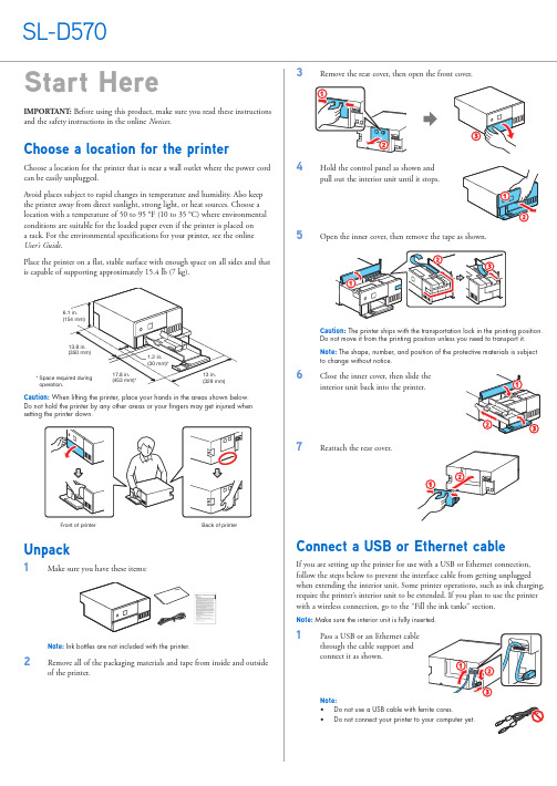
emove all of the packaging materials and tape from inside and outside2 O pen the cable holder located on the back of the printer, then passthe cable through the path as shown below. Pull the cable until thecable support is lowered, as shown below.Note: The cable support should remain loweredto ensure that the cable does not get disconnectedwhen pushing in or pulling out the interior unit.Fill the ink tanksWarning: Keep the ink bottles out of the reach of children and do not drink the ink. Caution: This product requires careful handling of ink. If ink spills, wipe it off immediately with a damp towel to avoid permanent stains. If ink gets on your clothes or belongings, it may not come off.Note:• F ill the ink tanks before turning on the printer.• M ake sure you have ink bottles available before starting the setup process.• P art of the ink will be used to charge the printhead. These bottles will print fewer pages compared with replacement ink bottles.• E pson strongly recommends the use of genuine ink to ensure optimal print quality and performance.1 O pen the printer’s front cover.2 H old the control panel as shown andpull out the interior unit until it stops.3 O pen the ink tank cover.4 O pen the cap for the Light Magenta (LM) ink tank.Note: Refer to the color-coded sticker on the ink tank unit to identify thecolor of each tank.5 U npack the Light Magenta (LM) ink bottle.Hold the ink bottle upright and slowly turnthe bottle cap to remove it.LMLMCaution: Do not shake or squeeze the ink bottle. Do not touch the top of theink bottle after its cap is removed.6 I nsert the ink bottle into the filling port.Note: Do not force the bottle into position; each bottle is keyed for each color.7 W ait for the ink to fill the tank. Do notsqueeze the bottle or allow it to contactany other surface.Note: Ink flows into the tank and stopsautomatically when the ink tank is filled to theupper line. If ink does not flow from the bottle,lift and reinsert the bottle.8 W hen the ink tank is full, remove the ink bottle and securely close itwith the bottle cap. If any ink remains in the bottle, store it for later use.Note: Do not leave the ink bottle inserted; otherwise the bottle may bedamaged or ink may leak. Once the ink tank is full, do not remove andreinsert the ink bottle or ink may spill.9 S ecurely close the Light Magenta ink tank cap.10 R epeat steps 4 through 9 for the other colors.11 C lose the ink tank cover.3Slide the edge guides all the way out. 4Lift the front edge guide until you see the two tabs on the bottom,then lower it, as shown.5Load paper with the printable side up and short edge first in the paper cassette, then slide the side edge guides against the paper, butnot too tightly.6R7Slide the front edge guide to the paper size indicator for the paper youloaded, then tap the paper against the front edge guide.Note: Make sure the paper stack is even to avoid paper feeding problems.8S9Set the paper size and paper type on the LCD screen, then highlight Close and press the OK button to confirm your selection.P ress the power button to turn on the printer. The powerlight flashes.15S elect your language, date, time, and unit settings.Note: You can change these settings later using the product’s control panel.For more information, see the online User’s Guide .16When the message to see the Setup Guide to complete installation appears on the LCD screen, follow the on-screen instructions. When prompted, press the OK button for 5 seconds to start charging the ink.Ink charging takes approximately 6 minutes.Note: When the power light stops flashing, ink charging is complete. Onceinitial setup of the printer is complete, you can top off the ink tanks with anyremaining ink. See the online User’s Guide for instructions.Caution: Do not unplug or turn off the product while the product is chargingor you’ll waste ink.17Press the OK button as prompted when ink charging is complete.Load paperThe printer can be used with 3.5 × 5-inch (9 × 13 cm) or 4 × 6-inch (10 × 15 cm) sheets of photo paper. See the online User’s Guide for information about loading capacity and available paper types.1O pen the front cover. 2P ull out the paper cassette.Note: Use both hands when pulling the paper cassette out to avoiddropping it.EPSON, Epson Smart Panel, and SureLab are registered trademarks and EPSON Exceed Your Vision is a registered logomark of Seiko Epson Corporation.Mac is a trademark of Apple Inc., registered in the U.S. and other countries.Android and Google Play are trademarks of Google LLC.Windows is a registered trademark of Microsoft Corporation in the United States and/or other countries.Mopria is a registered trademark of Mopria Alliance, Inc. in the United States and other countries.General Notice: Other product names used herein are for identification purposes only and may be trademarks of their respective owners. Epson disclaims any and all rights in those marks.This information is subject to change without notice.© 2023 Epson America, Inc., 1/23Printed in U.S.A.CPD-63229Install softwareNote: An internet connection is required to obtain the product software.1M ake sure the product is NOT CONNECTED to your computer.Windows ®: If you see a Found New Hardware screen, click Cancel andunplug the USB cable.2Download and run your product’s software package. For the latest software, visit /support/sld570 (U.S.), http://epson.ca/support/sld570 (Canada), or/support/sld570 (Latin America).3Follow the instructions on the computer screen to run the setup program.Mobile printingConnect wirelessly from your smartphone, tablet, or computer.• P rint directly from your Android TM(v4.4 or later) device*. Simply connect your printer and device to the same network and tap the menu icon to select the print option.• T urn your mobile device into an intuitive, easy-to-use printing control center with Epson Smart Panel ®. Download the app from your mobile device’s app store.* May require the Epson Print Enabler or Mopria ®Print Service app from Google Play ™.Using the Maintenance ToolOpen the Maintenance Tool software utility to perform the following maintenance tasks:• D iagnostic Cleaning – Detects clogged nozzles and automatically performs cleaning • F orced Cleaning – Performs manual cleaning • N ozzle Check – Checks for clogged nozzlesNote: See the online User’s Guide for details on using the Maintenance Tool utility.Product supportEpson technical supportVisit /support/sld570 (U.S.), http://epson.ca/support/sld570 (Canada), or/support/sld570 (Latin America) to download software and utilities, view manuals, get FAQs, or contact Epson.Epson provides technical support and information on the installation,configuration, and operation of professional printing products through your Epson limited warranty. Dial (888) 377-6611, 7 a.m. to 4 p.m., Pacific Time, Monday through Friday. Days and hours of support are subject to change without notice. Before you call, make sure you have your:• Printer serial number: _________________________________________• Proof of purchase and date: _____________________________________Note: If you experience difficulty with the toll-free line, call (562) 276-1305.In Latin America, see the online Notices for technical support information.Online guidesInstructions for using your printer and maintenance tools.RecyclingEpson offers a recycling program for end of life hardware and ink bottles. Please go to /recycle (U.S.) or http://epson.ca/recycle (Canada) for information on how to return your products for proper disposal.Need ink or paper?Ensure brilliant results with Epson ®specialty and plain papers, engineered specifically for Epson printers. Find Epson papers and Epson Genuine Ink at (U.S. sales) or http://epson.ca (Canadian sales) and at Epson authorized resellers. Call 800-GO-EPSON (800-463-7766).In Latin America, go to for purchase information.SL-D570 replacement ink bottles。
philips+fwd570+dvd+mini-hifi+system+中文+使用手册说明书
DVD Mini-HiFi SystemFWD570lilIndexEnglish------------------------------------------------6Español---------------------------------------------94----------------------------------------------138Manufactured under license from Dolby Laboratories.“Dolby”,“Pro-logic” and the double-D symbol are trade-marks of Dolby Laboratories.MANUFACT URED UNDER LICENSE FROM DIGITALT HEAT ER SYST EMS, INC. US PAT. NO 5,451,94;5,956,674; 5,974,380; 5,978,762; 6,226,616;6,487,535AND OTHER U.S.AND WORLDWIDE PATENTS ISSUEDAND PENDING.“DTS” AND “DTS DIGITAL SURROUND”ARE REGISTERED TRADEMARKS OF DIGITAL THEATERSYST EMS, INC. COPYRIGHT 1996, 2003 DIGIT ALTHE- ATER SYSTEMS,INC.ALL RIGHTS RESERVED.This product incorporates copyright protection technologythat is protected by method claims of certain U.S.patentsand other intellectual property rights owned by MacrovisionCorporation and other rights e of this copyrightprotection technology must be authorized by MacrovisionCorporation,and is intended for home and other limitedviewing uses only unless otherwise authorized byMacrovision Corporation.Reserve engineering or disassem-Español---------------------------------------------50目錄一般事項/維護保養功能特點 (140)可播放的光碟 (140)區碼隨機配件 (140)環保資訊 (141)維護保養與安全須知 (141)連接端子步驟 1:放置揚聲器 (142)步驟 2:連接揚聲器 (142)步驟 3:連接電視機...................................143~144使用視頻輸入(Video In) 端子(CVBS)使用色差視頻輸入(Component Video In)端子(Pr Pb Y)使用 S-視頻(S-Video In) 輸入端子使用外接的 RF 射頻調制器步驟 4:連接 FM/MW 天線 (145)步驟 5:連接電源線 (145)步驟 6:連接一台 VCR 錄影機或有線/衛星電視機頂盒 (146)步驟 7:連接數碼音頻設備 (146)步驟 8:連接到遊戲機控制台 (146)功能概述主機上的控制鍵...........................................147~148遙控器...............................................................148~149基本功能即插即播 (用於收音機安裝) (150)示範模式 (150)準備工作步驟 1:裝入遙控器電池 (151)步驟 2:設定時鐘........................................151~152步驟 3:設定電視機 (152)步驟 4:設定揚聲器 (153)步驟 5:設定優先語言 (153)遊戲操作使用前的準備工作 (154)開始操作 (154)光碟操作播放光碟 (155)使用光碟菜單 (155)基本的播放操作 (156)跳至另一標題 (曲目) /章節快速搜尋從上次停止的位置開始繼續播放選擇不同的播放模式.................................156~157重複播放模式亂序播放模式重複播放章節/ 曲目中的某個節段編設喜愛的曲目 (157)播放期間更換光碟 (158)DVD/VCD 特別功能.................................158~160改變字幕語言改變聲道語言搜索某一段落播放期間顯示光碟資料移至另一標題 (曲目) /章節從所選位置開始播放一些操作能夠無須中斷影碟的播放而直接經由電視屏幕上的菜單條進行以慢動作模式播放放大從另一角度觀看逐幀播放設定揚聲器查閱 DVD 影碟的內容VCD/SVCD 特別功能 (160)播放控制 (PBC)MP3/ WMA/DivX/ 圖片光碟的操作播放 MP3/ WMA/ 圖片光碟 (柯達, JPEG)......... (161)播放 DivX光碟 (162)DVD 菜單操作使用菜單條 (163)使用設置菜單(用戶偏好設定)............164~168設定電視形狀設定屏幕保護程式設定數碼輸出設定 PCM 輸出夜間模式 - 開啟/關閉音調測試DivX(R) VOD改變密碼通過設定家長控制級別來限制播放目錄收音機操作調諧選台 (169)預設電台..........................................................169~170自動預設電台手動預設電台選擇預設電台 (170)刪除預設電台改變調諧頻階 (170)磁帶操作/錄音磁帶播放 (171)關於錄音的一般說明 (171)錄音準備工作 (172)光碟同步播放及錄音 (172)時鐘/計時器操作查看時鐘 (173)設定計時器.....................................................173~174查看計時器 (174)設定關機計時器 (174)音效和音量控制音效控制 (175)選擇環繞音效MAX 音效選擇音響效果音量控制 (175)改變音量大小暫時關閉音量透過耳筒聆聽其他功能開機∕關機 (176)開機將本機切換至待機模式切換至省電待機模式省電自動待機模式使顯示屏變暗 (176)聲音控制 (Vocal) (176)音調控制 (Key control) (177)迴音 (Echo) (177)卡拉 OK (177)聆聽外接聲源 (177)技術規格 (178)故障排除...............................................179~180字彙集 (181)一般事項/維護保養功能特點你這套具有兩聲道全數碼式擴音機的 DVD Mini Hi-Fi 系統能營造出你在正規電影院所體驗到的那種動感聲音品質,並把家庭影院技術的一些最佳功能特點納入其內。
Maxtor 3.5系列硬盘说明书

ቤተ መጻሕፍቲ ባይዱ
Maxtor 3.5 series 40gb manual
Maxtor 3.5 series. Maxtor 3.5 series hard drive.
Maxtor Computer Drive Datasheet Maxtor Computer Drive User Manual Maxtor Computer Drive User Manual Maxtor Internal Hard Drive Kit Datasheet Maxtor Computer Drive User Manual Maxtor SCSI Hard Drive Specification Sheet Maxtor Computer Drive User Manual Maxtor External Storage Product Brochure Maxtor Computer Drive User Manual Maxtor SCSI Drive Specification Sheet Maxtor Computer Drive User Manual Maxtor Computer Drive Datasheet Maxtor Computer Drive User Manual Maxtor Computer Drive User Manual Maxtor Shared Storage Plus+ Quick Start Guide Maxtor Computer Drive User Manual Maxtor Hard Drive Product Overview Maxtor Computer Drive Specification Sheet Maxtor Fireball 541DX 2B020H1 Hard Drive Manual Maxtor Computer Drive Manual Maxtor Computer Drive Manual Maxtor Computer Drive Datasheet Maxtor Computer Drive User Manual Maxtor Hard Drive Product Brochure Maxtor Hard Drive Product Brochure Maxtor External Hard Drive Product Brochure Maxtor Personal Storage External Hard Drive Brochure Maxtor External Hard Drive Product Brochure Maxtor External Hard Drive Product Brochure Maxtor Internal Hard Drive Kit Datasheet Maxtor External Hard Drive Product Brochure Maxtor Computer Drive Datasheet Maxtor Hard Drive Brochure Maxtor Computer Drive User Manual Maxtor Computer Drive User Manual Maxtor ATA Hard Drive Datasheets Maxtor ATA Hard Drive Datasheets Maxtor ATA Hard Drive Datasheets Maxtor ATA Hard Drive Datasheets Maxtor ATA Hard Drive Datasheets Maxtor ATA Hard Drive Datasheets Maxtor ATA Hard Drive Datasheets Maxtor ATA Hard Drive Datasheets Maxtor ATA Hard Drive Datasheets Maxtor ATA Hard Drive Datasheets Maxtor Computer Drive User Manual Maxtor External Hard Drive Product Brochure Maxtor Computer Drive User Manual Maxtor Computer Drive Datasheet Maxtor Computer Drive User Manual Pour rechercher une notice, utilisez le moteur de recherche tout en haut de page (à coté de la loupe). Vous trouvez que la notice de votre MAXTOR est illisible ? Elle n'est pas dans votre langue d'origine ? Vous avez besoin de la notice d'emploi. Quel que soit le problème que vous rencontrez, vous trouverez ici tout ce qu'il faut savoir sur l'utilisation de votre MAXTOR. Télécharger gratuitement et sans inscription plusieurs types de documents pour mieux utiliser votre produit : mode d'emploi, notice d'utilisation, manuel d'instruction. © 1996-2014, , Inc. or its affiliates
步步高VS570说明书
长时间不使用本机,请将电源插头拔离插座。 本机使用的是开关电源,电源使用交流~220V,频率50/60Hz,请确认当地电压与本机工作电压相符,否则将不能 播放, 甚至烧坏本机。 为延长本机使用寿命,连续开关机时间必须在30秒以上。 开启电源前,请确认各种连线和电源线已完全正确地连接。 不要将主机靠近大功率音箱或将它们放在同一台面上,以防震动而影响本机正常工作。 请将本机置于通风干燥处。防止靠近热源,远离阳光直射、机 械振动、潮湿和较多灰尘的环境,以及避免置于其它热 辐射物体的顶部。 主机从一个较冷地方移至较暖地方,或从一个较暖地方移至较冷地方时,光头可能会结露,机器不能正常工作。如 遇 此情况,请将电源打开1 2小时后(不要放入碟片),方可进行碟片的播放操作。 可用少许中性洗涤剂清洁机器,切勿用砂纸或酒精、汽油等 有机溶剂。
○
○
○
○
○
○
○
○
○
○
○
○
○
○
○
○
○
○
○
○
×
○
○
○
○
○
○
○
○
○
○
○
○
○
○
○
○
○
○
○
○
○
○
○
○
○
○
○
○
○
○
○
○
○
○
○
○
○
○
○
×
○
○
○
×
○
○
○
×
○
○
○: 表示该有毒有害物质在该部件所有均质材料中的含量均在S J/ T 11363 - -2 0 0 6规定的限量要求以下。 ×: 表示该有毒有害物至少在该部件的某一均质材料中的含量超出S J /T 1 1 3 6 3- -2006 规定的限量要求。 注: 本产品8 0% 的部件采用无毒无害的环保材料制造, 含有有毒有害物质或元素皆因目前技术和经济上限制而无法实现
技嘉X570SAEROGAERO新系列主板评测
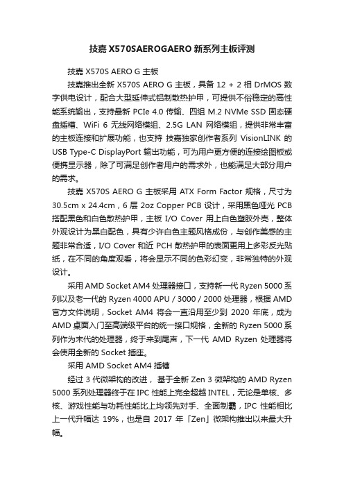
技嘉X570SAEROGAERO新系列主板评测技嘉 X570S AERO G 主板技嘉推出全新 X570S AERO G 主板,具备 12 + 2 相 DrMOS 数字供电设计,配合大型延伸式铝制散热护甲,可提供不俗稳定的高性能系统输出,支持最新 PCIe 4.0 传输、四组 M.2 NVMe SSD 固态硬盘插槽、WiFi 6 无线网络模组、2.5G LAN 网络模组,提供非常丰富的主板连接和扩展功能,也支持技嘉独家创作者系列VisionLINK 的USB Type-C DisplayPort 输出功能,可为用户更方便的连接绘图板或便携显示器,除了可满足创作者用户的需求外,也能满足大部分用户的需求。
技嘉 X570S AERO G 主板采用 ATX Form Factor 规格,尺寸为30.5cm x 24.4cm,6 层 2oz Copper PCB 设计,采用黑色哑光 PCB 搭配黑色和白色散热护甲,主板I/O Cover 用上白色塑胶外壳,整体外观设计为黑白配色,具有少许白色主题风格成份,与创作美感的主题非常合适,I/O Cover 和近 PCH 散热护甲的表面更用上多彩反光贴纸,在不同的角度观看,将会显示不同的色彩幻变,非常独特的外观设计。
采用 AMD Socket AM4 处理器接口,支持新一代 Ryzen 5000 系列以及老一代的 Ryzen 4000 APU / 3000 / 2000 处理器,根据 AMD 官方文件说明,Socket AM4 将会一直沿用至少到2020 年底,成为AMD 桌面入门至高端级平台的统一接口规格,全新的 Ryzen 5000 系列作为末代的处理器,终于来到尾声,下一代AMD Ryzen 处理器将会使用全新的 Socket 插座。
采用 AMD Socket AM4 插槽经过 3 代微架构的改进,基于全新 Zen 3 微架构的 AMD Ryzen 5000 系列处理器终于在 IPC 性能上完全超越 INTEL,无论是单核、多核、游戏性能与功耗性能比上均领先对手、全面制霸,IPC 性能相比上一代升幅达19%,也是自2017 年「Zen」微架构推出以来最大升幅。
DLong桑拿手册

DLONGXP酒店管理系统桑拿用户使用手册目录第二章基本常识 (5)第一节开启系统 (5)第二节一般常识 (6)第三节重新登录 (6)第四节修改口令 (6)第五节退出系统 (7)第三章准备工作 (8)第一节基本参数 (8)第二节技师档案 (10)第三节消费项目维护 (11)第四节匙号维护................................ 错误!未定义书签。
第五节房价设置................................ 错误!未定义书签。
第六节权限管理 (14)第七节系统参数设置 (15)第四章开单收银 (15)第一节下单操作流程 (17)4.1.1 钟房浏览 (17)4.1.2 开单 (17)4.1.3 改单.................................... 错误!未定义书签。
4.1.4 消项 (20)4.1.5 折扣.................................... 错误!未定义书签。
4.1.6 结算.................................... 错误!未定义书签。
4.1.7 帐单打印 (23)第二节拼单、分单处理 (23)第三节历史帐单浏览 (23)第四节取消已结帐标致 (24)第五章会员管理 (24)第六章实时台态 (25)第七章报表 (26)第八章交班日结 (27)第一节交接班流程 (27)第二节日结束处理 (28)第九章报表转存数据处理 (29)第一节报表转存网页 (29)第二节报表转存E XECL (29)附录:小键盘操作及快捷键说明 (30)第一章前言第一节如何使用本手册本手册是DLongxp酒店管理系统的配套资料。
如果您是酒店的行政管理人员、业务管理人员或电脑系统管理人员,在您开始本系统实施电脑管理前,您应该对本系统功能、性能、操作方法等有足够的了解。
作为一般的操作人员,首先,应该对酒店业务本身有足够的了解;其次,上岗操作本系统前,应该接受过足够的培训;再次,应该获得酒店管理人员的许可;最后,还需要得到系统管理员分配权限。
电脑硬盘参数详解
希捷(Seagate),日立(HITACHI),迈拓(Maxtor),西部数据(Western Digital)和三星(Samsung)一、希捷(Seagate)Seagate硬盘的编号比较简单,其识别方法为:“ST+硬盘尺寸+容量+主标识+副标识+接口类型” 。
为了另大家容易理解,简单的表示形式为:ST“X,XXXX,XX,XXX”,也就是说其硬盘编号可以分为四部分。
首先,“ST”代表的是“Seagate”,也就是说是希捷公司的产品。
然后第一部分的“X”是表示其硬盘外形和尺寸。
“1”表示3.5英寸,厚度为41mm的全高硬盘;“3”表示3.5英寸,厚度为25mm的半高硬盘;“4”表示5.25英寸,厚度为82mm的硬盘;“5”表示尺寸为3.5英寸,厚度为19mm的硬盘;“9”表示为尺寸2.5英寸的硬盘。
第二部分的四个“X”是表示硬盘的容量,通常由3到4位数字组成,单位是GB。
如:“1600”就是表示这硬盘的容量为160GB,而“400”或者“800”就表示其容量为40GB或者80GB了。
第三部分的两个“X”为硬盘标志,由主标志和副标志所组成。
前一个数字是主标志,在Seagate的IDE硬盘中都是指硬盘的碟片数,如数字“2”则表示该硬盘采用了2张盘片。
而在Seagate的SCSI硬盘中,其主标识则是指硬盘的转速了。
有了主标识当然就会有副标识了,而后一个数字就是副标识。
它是只有当主标识相同或者无效时,副标识才有意义。
它一般代表硬盘的性能和代数,当数字越大,表示的代数越高,性能越好,此款硬盘也就越新。
第四部分的三个“X”主要由1到3个字母所组成,表示硬盘接口类型等。
一般的桌面IDE硬盘较为简单,但如果包括了现在和早期的SCSI硬盘的话,其含义就变得较为复杂了。
“A”表示为ATA UDMA/33或UDMA/66 IDE的接口“AS”表示为Serial ATA150的接口“AG”表示为笔记本电脑专用的ATA的接口“N”表示为50针Ultra SCSI的接口,其数据传输率为20MB/s“W”表示为68针Ultra SCSI接口,其数据传输率为40MB/s“WC”表示为80针Ultra SCSI的接口“FC”表示为光纤,可提供高达100MB/s的数据传输率,并且支持热拔插“WD”表示为68针Ultra Wide SCSI的接口“LW”表示为68针Ultra-2 SCSI(LVD)的接口“LC”表示为80针Ultra-2 SCSI(LVD)的接口我们以Seagate酷鱼硬盘“ST3160023AS”为例子,通过例子的编号我们可以知道该硬盘是希捷公司生产的3.5英寸厚度为25mm的半高硬盘,其采用2张硬盘盘片,总容量是160GB的Serial ATA150。
- 1、下载文档前请自行甄别文档内容的完整性,平台不提供额外的编辑、内容补充、找答案等附加服务。
- 2、"仅部分预览"的文档,不可在线预览部分如存在完整性等问题,可反馈申请退款(可完整预览的文档不适用该条件!)。
- 3、如文档侵犯您的权益,请联系客服反馈,我们会尽快为您处理(人工客服工作时间:9:00-18:30)。
1/4
TARGET DATA
May 2000
PD57030PD57030S
RF POWER TRANSISTORS The LdmoST Plastic FAMILY
N-CHANNEL ENHANCEMENT-MODE LATERAL MOSFETs
•EXCELLENT THERMAL STABILITY •COMMON SOURCE CONFIGURATION •POUT =30W with 13dB gain @945MHz /28V •NEW RF PLASTIC PACKAGE
DESCRIPTION
The PD57030is a common source N-Channel,en-hancement-mode,lateral Field-Effect RF power transistor.It is designed for high gain,broad band commercial and industrial applications.It operates at 28V in common source mode at frequencies of up to 1GHz.PD57030boasts the excellent gain,linearity and reliability of ST’s latest LDMOS tech-nology mounted in the first true SMD plastic RF power package,PowerSO-10RF.PD57030’s su-perior linearity performance makes it an ideal so-lution for base station applications.
The PowerSO-10plastic package,designed to of-fer high reliability,is the first ST JEDEC approved,high power SMD package.It has been specially optimized for RF needs and offers excellent RF performances and ease of assembly.
PowerSO-10RF (Formed Lead)
ORDER CODE BRANDING PowerSO-10RF
(Straight Lead)
ORDER CODE BRANDING PD57030XPD57030
PD57030S XPD57030S
ABSOLUTE MAXIMUM RATINGS (T CASE =250C)
Symbol Parameter
Value Unit V (BR)DSS Drain-Source Voltage 65V V GS Gate-Source Voltage ±20V I D Drain Current
4A P DISS Power Dissipation (@Tc =700C)52.8W
T j Max.Operating Junction Temperature 1650C
T STG
Storage Temperature
-65to 175
0C
THERMAL DATA (T CASE =700C)
R th(j-c)Junction-Case Thermal Resistance
1.8
0C/W
PD57030PD57030S
2/4
PIN CONNECTION
SOURCE
DRAIN GATE
SC15200
ELECTRICAL SPECIFICATION(T CASE=250C)
STATIC
Symbol Parameter Min.Typ.Max.Unit V(BR)DSS V GS=0V I DS=10mA65V
I DSS V GS=0V V DS=28V1µA
I GSS V GS=20V V DS=0V1µA
V GS(Q)V DS=28V I D=50mA 2.0 5.0V V DS(ON)V GS=10V I D=3A 1.3V
g FS V DS=10V I D=3A 1.8mho
C ISS V GS=0V V DS=28V f=1MHz57pF
C OSS V GS=0V V DS=28V f=1MHz30pF
C RSS V GS=0V V DS=28V f=1MHz 1.4pF
DYNAMIC
Symbol Parameter Min.Typ.Max.Unit P OUT V DD=28V f=945MHz I DQ=50mA30W
G PS V DD=28V f=945MHz P OUT=30W I DQ=50mA1314dB
ηD V DD=28V f=945MHz P OUT=30W I DQ=50mA5060%
LOAD Mismatch V DD=28V f=945MHz P OUT=30W I DQ=50mA
ALL PHASE ANGLES
10:1VSWR
PD57030PD57030S PowerSO-10RF(Straight Lead)MECHANICAL DATA
PowerSO-10RF(Formed Lead)MECHANICAL DATA
3/4
PD57030PD57030S
Information furnished is believed to be accurate and reliable.However,STMicroelectronics assumes no responsibility for the consequences of use of such information nor for any infringement of patents or other rights of third parties which may result from its use.No license is granted by implication or otherwise under any patent or patent rights of STMicroelectronics.Specifications mentioned in this publication are subject to change without notice.This publication supersedes and replaces all information previously supplied.STMicroelectronics products are not authorized for use as critical components in life support devices or systems without express written approval of STMicroelectronics.
The ST logo is registered trademark of STMicroelectronics
®2000STMicroelectronics-All Rights Reserved
All other names are the property of their respective owners.
STMicroelectronics GROUP OF COMPANIES
Australia-Brazil-China-Finland-France-Germany-Hong Kong-India-Italy-Japan-Malaysia-Malta-Morocco-
Singapore-Spain-Sweden-Switzerland-United Kingdom-U.S.A.
4/4。