高频波形发生器
高频发生器使用方法说明书

高频发生器使用方法说明书1. 概述高频发生器是一种用于产生高频信号的设备,广泛应用于通信、无线电、医疗等领域。
本说明书将详细介绍高频发生器的使用方法,包括操作步骤、注意事项和常见故障处理等内容,帮助您正确、安全地操作高频发生器。
2. 基本操作步骤2.1 准备工作在使用高频发生器之前,请确保以下准备工作完成:- 将高频发生器放置在稳定的工作台面上,避免摇晃和倾斜;- 将高频发生器与配套的电源线连接,并插入符合标准的电源插座。
2.2 打开电源将高频发生器的电源开关调至“ON”位置,此时设备开始供电。
2.3 设置频率根据实际需求,将频率调节旋钮或通过操作面板上的按键进行调整。
请注意,在调整频率时应遵循以下步骤:- 先将频率调节旋钮或按键旋至最低值;- 缓慢、逐渐地调节频率,避免突然调至较高值。
2.4 调整输出功率高频发生器的输出功率通常可以进行调整。
请根据实际需求,进行适当的功率调整,但务必注意以下事项:- 不要将输出功率调至过高,以免损坏设备或引起危险;- 在调整输出功率时,可以通过连接功率计进行实时监测,确保输出功率符合要求。
2.5 连接外部设备高频发生器通常需要与其他设备进行连接,以便进行信号传输或测试。
请根据实际需求,正确连接相关设备,并确保连接安全可靠。
3. 注意事项3.1 安全操作在使用高频发生器时,务必注意以下安全事项:- 请勿拆卸设备外壳,以免触电或引起其他危险;- 使用电源插头和电源线时,请确保符合国家标准,并遵循正确的插拔步骤;- 在设备长时间工作后,应首先关闭电源,待设备冷却后再进行其他操作。
3.2 使用环境高频发生器应在干燥、通风良好的环境中使用,以确保设备正常运行和寿命。
请避免以下环境:- 高温、潮湿或多尘的场所;- 震动较大的场所;- 高磁场区域或有强电磁干扰的场所。
3.3 故障处理在使用高频发生器过程中可能会遇到一些常见故障,建议您尝试以下方法进行处理:- 若发生设备无法开机的情况,请首先检查电源连接是否正确,并确保电源正常;- 若发生频率异常或输出功率不稳定的情况,请检查频率调节旋钮或按键是否操作正确,并检查设备连接是否松动;- 若设备出现异常噪声或无法正常传输信号的情况,请检查设备连接线路是否异常,并尝试重新连接。
信号发生器的分类
信号发生器的分类信号发生器是电子测试仪器中常用的一种设备,用于产生不同频率、幅度和波形的电信号。
根据其功能和应用领域的不同,信号发生器可以分为多种类型。
本文将对几种常见的信号发生器进行分类和介绍。
一、函数发生器(Function Generator)函数发生器是最常见的一种信号发生器,它可以产生多种波形信号,如正弦波、方波、锯齿波和三角波等。
函数发生器可以根据用户的需求,通过调节频率、幅度和相位等参数,生成不同形态的信号。
它广泛应用于电子实验、通信测试和教学等领域。
二、任意波形发生器(Arbitrary Waveform Generator)任意波形发生器是一种高级的信号发生器,可以产生任意复杂的波形信号。
与函数发生器相比,任意波形发生器可以通过用户提供的采样点数据,生成非周期性的任意波形信号。
任意波形发生器在研发新产品、模拟真实信号和测试复杂系统等方面具有重要应用。
三、脉冲发生器(Pulse Generator)脉冲发生器是专门用于产生脉冲信号的设备。
脉冲发生器可以产生具有特定频率、宽度和占空比的脉冲信号,常用于数字电路测试、脉冲测量和脉冲信号调试等领域。
脉冲发生器还可以模拟各种脉冲干扰,用于电磁兼容性测试和抗干扰性能评估。
四、频率计(Frequency Counter)频率计是一种用于测量信号频率的设备,通常与信号发生器配合使用。
频率计可以精确地测量输入信号的频率,并显示在数码显示屏上。
频率计广泛应用于科研实验、无线通信、广播电视等领域,常用于校准信号发生器和检测频率稳定性。
五、噪声发生器(Noise Generator)噪声发生器是一种用于产生随机噪声信号的设备。
噪声发生器可以产生不同类型的噪声信号,如白噪声、粉噪声和高斯噪声等。
噪声发生器在通信系统测试、声学实验和信号处理等领域具有重要应用,可以模拟真实环境中的噪声情况。
六、微波信号发生器(Microwave Signal Generator)微波信号发生器是专门用于产生微波频率信号的设备。
智能高频精密函数波形发生器的设计
文章编号 : 0 — 25 20 )3 02 — 2 1 8 84 (06 0 — 0 3 0 0
智能高频精密 函数 波形发生器 的设计
彭德迟
( 黄石理工学院国际学院, 湖北 黄石 4 50 ) 303
摘 要: 介绍一种单片机集成电路 M X3 设计的智能信号发生器。 A 08 该仪器电路结构简单, 电路产/ ̄信 - v
收稿 日期 :05—1 0 20 2— 5 作者简介 : 彭德迟 (92 16一 )男 , 大冶人 , , 湖北 高级工程师 , 博士生 。
!
… …
MC4 11 155
… …
 ̄A 74 ; ' X 51 1
… … …
M X 3 A 08
_ … 一 ‘一
:
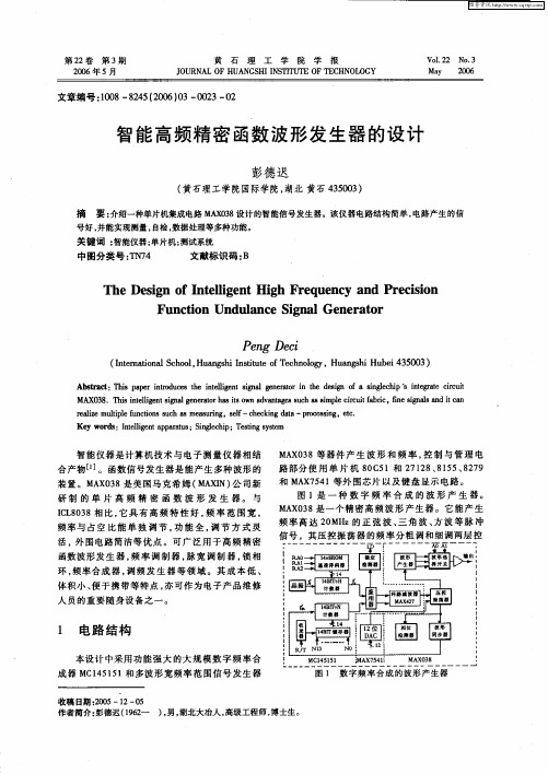
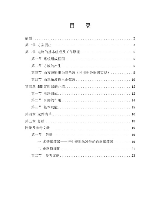
图 1 数 字 频 率 合 成 的 波形 产 生 器
:= 苎 ; 捆 苎囱 : 也 ; : J 匿H囡 j 【 垡 一 兰 妻 !
: 反 石 广 — t ; = i J _
披 形 同 步 嚣
!
1 电 路 结 构
本设计 中采用 功 能强 大 的 大规 模数 字 频 率合 成 器 M 15 5 C 4 11和多波 形宽频 率 范 围信号 发 生 器
图 1是 一 种 数 字 频 率 合 成 的 波 形 产 生 器 。 MA 0 8是一 个精 密 高 频 波形 产生 器 。它 能产 生 X3 频 率 高 达 2 MH 0 z的 正 弦 波 、 角 波 、 波 等脉 冲 三 方
信 号 ,其 压控 振荡 器 的频 率分 粗调 和细 调两层 控
号好 , 并能实现测量 , 自检 , 数据处理等多种功能 。
关键词 : 智能仪器; 单片机; 试系统 测
高频发生器工作原理
高频发生器工作原理
高频发生器是一种能够产生高频电信号的设备。
它通过使用一种射频源(例如晶体振荡器)产生稳定的高频信号。
该信号经过放大器进行放大,并且经过滤波器来去除不需要的谐波和干扰。
然后,处理后的信号被输出到感兴趣的设备或电路中。
高频发生器的工作主要依赖于基本的电子元件和电路,包括晶体振荡器、放大器和滤波器。
晶体振荡器是一个稳定的振荡器,它通过利用某种晶体材料的特性,在外加直流电压的作用下,产生稳定的高频信号。
这个信号经过放大器的放大,以保证信号的强度足够大以供后续电路使用。
然后,信号会经过滤波器,这是为了去除振荡器产生的频率之外的杂散信号。
滤波器使用不同的电感、电容和电阻组合,以选择性地通过或阻止特定频率范围的信号。
这有助于确保高频发生器输出的信号质量良好,并且不会引入无用的干扰。
最后,处理后的高频信号将用作其他设备或电路的输入信号。
这些设备可能是无线电通信设备、医疗设备、科学研究仪器等。
高频发生器的工作原理主要是通过合理地选择和组合各种电子元件和电路,以实现高频信号的稳定产生和适应性传输。
XFG—7高频信号发生器
[内容简介]一、概述:XFG—7高频信号发生器是一种载波频率范、调制度范围为(0—100%)连续可调的标准高频信号源。
可二、主要技术性能⒈频率范围:100HZ— 30MHZ 共分八个频段⒉频率刻度误差:±1%⒊输出阻抗与输出电压:⑴在“0—0.1V”插件中,接有分压电阻的电缆终端输出为接点“1”,输出电阻为“40Ω”,输出电压1μV~100000μV连续可调。
接点“0.1”输出电阻为“8Ω”,输出电压“0.1 μV~10000μV连续可调。
⑵在“0~1V“插件中,开路输出电压为0~1V连续可调,输出电阻为400Ω。
⑴内部调制频率有400HZ—和1000HZ两档,均为±5%⑵外部调制信号可用XD2低频信号发生器供给。
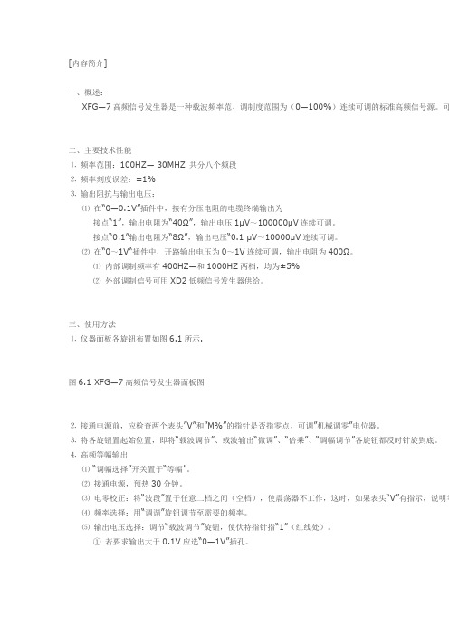
三、使用方法⒈仪器面板各旋钮布置如图6.1所示.图6.1 XFG—7高频信号发生器面板图⒉接通电源前,应检查两个表头”V”和”M%”的指针是否指零点,可调”机械调零”电位器。
⒊将各旋钮置起始位置,即将“载波调节”、载波输出“微调”、“倍乘”、“调幅调节”各旋钮都反时针旋到底。
⒋高频等幅输出⑴“调幅选择”开关置于“等幅”。
⑵接通电源,预热30分钟。
⑶电零校正:将“波段”置于任意二档之间(空档),使震荡器不工作,这时,如果表头“V”有指示,说明零⑷频率选择:用“调谐”旋钮调节至需要的频率。
⑸输出电压选择:调节“载波调节”旋钮,使伏特指针指“1”(红线处)。
①若要求输出大于0.1V应选“0—1V”插孔。
② 若要求输出在0.1V 以下应选“0—0.1V”插孔。
在根据所需输出电压选择输出插孔时,应调节“输出——倍乘”及“输出——微调”旋钮,必须使电压表“V”指 例如:如输出“0~0.1V”插孔,“输出——倍乘”指10,“输出——微调”指2,则在电缆终端0.1处的输出电⒌ 调幅波输出:⑴ 内调节:“调幅选择”放在“400 HZ”或“1000HZ”处。
调节“调幅度调节”由M%表直接按指示调幅度。
波形发生器原理

波形发生器原理波形发生器是一种能够产生各种波形信号的电子设备,它在许多电子领域中都有着广泛的应用,比如在通信、测试仪器、医疗设备等领域。
波形发生器的原理是基于信号发生器的基本原理,通过不同的电路结构和控制方式,可以产生不同类型的波形信号,如正弦波、方波、三角波和锯齿波等。
波形发生器的基本原理是利用振荡电路产生一定频率和幅度的周期性信号。
振荡电路是由放大器、反馈网络和反馈元件组成的。
当反馈网络和反馈元件满足一定的条件时,放大器就会产生自激振荡,输出一定频率和幅度的信号。
波形发生器可以通过调节反馈网络和反馈元件的参数,来改变输出信号的频率和幅度,从而实现不同类型的波形信号的产生。
在波形发生器中,常用的振荡电路包括晶体振荡器、RC振荡器和LC振荡器等。
晶体振荡器是利用晶体谐振的特性产生稳定的高频信号,适用于需要高频率和稳定性的场合。
RC振荡器是利用电容和电阻构成的振荡网络产生信号,适用于低频和中频范围。
LC振荡器则是利用电感和电容构成的振荡网络产生信号,适用于需要较高频率和较高稳定性的场合。
除了振荡电路,波形发生器还需要一些控制电路来实现对输出波形的调节和控制。
比如,通过控制电压控制振荡电路的频率和幅度,通过数字控制接口实现对波形发生器的编程控制等。
这些控制电路可以使波形发生器具有更灵活的功能,满足不同应用场合的需求。
总的来说,波形发生器是一种能够产生各种波形信号的电子设备,它的原理是基于振荡电路产生一定频率和幅度的信号,通过控制电路实现对输出波形的调节和控制。
波形发生器在电子领域中有着广泛的应用,是许多电子设备中不可或缺的部分。
希望本文对波形发生器的原理有所帮助,谢谢阅读!。
波形发生器使用方法说明书
波形发生器使用方法说明书1. 简介波形发生器是一种电子测试设备,用于产生各种波形信号,如正弦波、方波、三角波等。
本说明书旨在介绍波形发生器的基本使用方法,帮助用户正确操作设备。
2. 设备介绍波形发生器通常由以下几个主要部分组成:- 波形选择器:用于选择不同的波形类型。
- 频率调节器:用于调节输出波形的频率。
- 幅度调节器:用于调节输出波形的峰值幅度。
- 输出接口:用于连接到被测设备或电路,将波形信号输出。
3. 使用步骤步骤1: 将波形发生器连接到电源,并确保设备已开启。
步骤2: 使用波形选择器选择所需的波形类型,可以是正弦波、方波、三角波等。
步骤3: 使用频率调节器设置所需的输出频率。
可根据具体需求调节频率范围,如几赫兹到几兆赫兹。
步骤4: 调节幅度调节器以设置所需的输出信号幅度。
步骤5: 将输出接口连接到被测设备或电路,确保连接稳固。
步骤6: 开始输出波形信号,并观察被测设备或电路的反应。
4. 注意事项- 在操作过程中,应遵循设备的安全操作规范,确保设备正常工作。
- 避免将波形发生器连接到超过其额定电压和电流范围的设备或电路。
- 当设备闲置时,应将频率和幅度调节器调整至最小值,并关闭设备。
- 注意确保输出接口的连接正确,并避免与其他接口短路或接触不良。
5. 故障排除在使用波形发生器过程中,可能会遇到以下问题:- 无法输出信号:检查设备的电源连接是否正常,确认频率、幅度调节器是否设置正确。
- 输出信号波形不准确:检查设备的波形选择器是否选择正确,确保连接稳固。
6. 维护与保养- 定期清洁设备表面,避免灰尘和污垢积累。
- 避免设备受潮或与液体接触,并保持设备在干燥的环境中。
- 注意防止设备遭受冲击或摔落,避免造成损坏。
本说明书介绍了波形发生器的基本使用方法,涵盖了设备介绍、使用步骤、注意事项、故障排除以及维护与保养等内容。
希望能帮助用户正确使用波形发生器,确保其正常工作及延长设备的使用寿命。
如有其他问题或需求,请参阅设备的详细说明书或联系生产厂商。
SIGLENT SDG7000A 系列双通道任意波形发生器数据手册说明书

数据手册CN01B产品综述SDG7000A 系列双通道任意波形发生器,最大带宽1 GHz,具备5 GSa/s数-模采样率和14-bit 垂直分辨率,能够产生最高2.5 GSa/s采样率的逐点任意波和最大500 MSymbol/s的矢量信号,同时还具备连续波、脉冲信号、噪声、PRBS码型和16-bit数字总线等多种信号生成的能力,并提供调制、扫频、脉冲串和双通道复制、相加、互相调制等复杂信号的生成能力,是一款高端多功能波形发生器。
其输出支持差分/单端切换,最大可提供±24 V的输出范围,并且在高频输出下仍然能保证较大的幅度,可在一定应用范围内节省外接功放,满足更广泛的需求。
特性与优点⏹双通道差分/单端模拟输出,16-bit LVDS/LVTTL数字总线输出⏹ 5 GSa/s数-模转换器采样率,14-bit垂直分辨率⏹最高输出频率1 GHz⏹可输出0.01 Sa/s ~ 2.5 GSa/s采样率的逐点任意波,最大存储深度512 Mpts,提供分段编辑和播放的功能⏹可输出最高500 MSymbol/s符号率的矢量信号⏹可输出最小脉宽1 ns,最小沿500 ps的低抖动脉冲,上升/下降沿独立精细可调,脉宽精细可调⏹可输出1 mHz ~ 1 GHz带宽的高斯噪声⏹可输出最高312.5 Mbps的PRBS码型⏹数字总线可输出最高1 Gbps的数字信号⏹提供多种模拟/数字调制,提供扫频和脉冲串功能⏹增强的双通道操作功能:通道间跟踪、耦合和复制功能;双通道叠加功能;支持通道间互为调制源⏹24 Vpp模拟输出能力叠加±12 V直流偏置,最大可提供±24V(48 V)的输出范围⏹硬件频率计功能⏹5英寸电容式触摸显示屏,分辨率800x480;支持外接鼠标和键盘操作;内建的WebServer 支持通过网页控制仪器⏹丰富的接口:USB Host、USB Device (USBTMC)、LAN(VXI-11/Telnet/Socket)、外调制/频率计输入、参考时钟输入、参考时钟输出、Marker输出、Trigger In/Out等⏹支持SCPI 远程控制命令,良好适配各种自动化集成测试系统SDG7000A任意波形发生器数据手册型号和主要参数SDG7000A任意波形发生器数据手册设计特色多功能信号发生器SDG7000A是一款集多种信号发生器功能于一体的产品。
33600A系列Trueform波形发生器简介

典型 DDS 发生器具有更高的本底噪声和谐波。
9 | Keysight | 33600A 系列 Trueform 波形发生器-技术资料
信号完整性(续)
生成更低电压输出信号
如今的超小功率产品均使用极低的电压,例如起搏器、助听器 和远程传感器。33600A 系列支持您生成低至 1 mVpp 的信号, 其电压范围仅为典型波形发生器的 10%。
– 轻松生成您所预期的全部信号, 让您从容应对任何严苛 的测试环境
– 确保波形发生器能够输出预期信号, 使您可以信心十足 地测试自己的器件
– 根据您当前所需选择配置, 并根据未来需求变化轻松升级
33600A 系列波形发生器的独有特性
100 MHz 脉冲 PRBS 码型 2 通道耦合 组合信号 TRUEFORM 任意波形 低电压设置 频段受限噪声
在 33600A 系列波形发生器中轻松生成 PRBS 波形。
使用智能手机和平板电脑访问全部文档
需要快速获得答复?通过适用于智能手机的 WebHelp 格式用户 界面,您可以即时访问七国语言的仪器文档。您可以通过手中 的智能设备浏览所有用户文档,无需使用 PC 或印刷版手册。其 他同类函数/任意波形发生器不具备这一特性。
Trueform
波形排序
波形排序功能使您可以利用若干普通片段创建多种配置波形, 使用最少的仪器存储器生成更长、更复杂的波形。
Trueform
在 33503A Waveform Builder Pro 中 生成波形, 并下载到波形发生器。
DDS 技术会 跳过高带宽上的
波形点
DDS 可能会丢失波形细节
DDS
全带宽调制源
无需使用外部调制源。33600A 系列的调制频率可以达到被调制 波形的频率。现有 DDS 发生器的内部调制频率远远低于这一频 率。您现在能够在一台发生器中生成全部复杂信号。
33611a波形发生器技术指标
33611a波形发生器的主要技术指标如下:1. 频率范围:该波形发生器的工作频率范围通常在几十赫兹到几兆赫兹之间,具体频率范围会根据型号和产品说明有所不同。
2. 波形种类:该波形发生器可以产生多种波形,如正弦波、方波、三角波、锯齿波等,具体可产生哪种波形会根据型号和产品说明有所不同。
3. 输出幅度:该波形发生器的输出幅度通常可以通过软件或硬件进行调节,具体的输出幅度会根据型号和产品说明有所不同。
4. 输出阻抗:该波形发生器的输出阻抗通常为50欧姆,但也可能因型号和产品说明有所不同。
5. 精度等级:该波形发生器的精度等级通常较高,可以达到小数点后两位的精度,但也可能因型号和生产厂家不同而有所差异。
6. 电源电压:该波形发生器通常需要使用5伏到12伏的直流电源供电,具体电压范围会因型号而异。
7. 工作温度:该波形发生器的工作温度通常在-5℃到50℃之间,但也可能因型号和生产厂家不同而有所差异。
8. 存储温度:该波形发生器可以在-20℃到70℃之间的温度下正常存储,但也可能因型号和生产厂家不同而有所差异。
除了以上基本的技术指标,33611a波形发生器还具有一些其他的特点和应用优势:1. 精度高、稳定性好:由于其高精度和良好的稳定性,该波形发生器在各种测试和测量应用中具有广泛的应用价值。
2. 适应性强:该波形发生器可以在不同的工作环境和条件下正常工作,具有较好的适应性。
3. 动态范围广:该波形发生器可以产生从低频到高频的信号,具有较广的动态范围。
4. 可编程性:一些现代的33611a波形发生器可以通过软件编程进行定制,可以根据不同的应用需求产生特定的波形。
总之,33611a波形发生器是一种具有多种特性和优势的设备,在各种测试和测量应用中具有广泛的应用价值。
在实际使用中,用户可以根据具体需求和环境条件选择合适的型号和配置,并参考产品说明进行正确的使用和维护。
高频发生器使用说明书

4642 N. RAVENSWOOD, CHICAGO, ILLINOIS 60640-4510TELEPHONE: 1-773-561-2349FAX: 1-773-561-3130Model BD-10A /BD-10AS HIGH FREQUENCY GENERATORPRODUCT NUMBER 11011 / 11031INSTRUCTIONSDESCRIPTION. The Model BD-10A and BD-10AS are hand-held units which generate a high voltage at a high frequency. It is intended for intermittent use, no more than 10 minutes at a time. It has an output of between 20,000 to 45,000 volts, at a frequency of approximately 500 kHz. When properly adjusted, when the electrode is held within ¼ to 1 in. (6 to 25 mm) from a metal object, a spark will jump to the metal. Current output of the spark is about 1 mA.The Model BD-10AS (illustrated above) has a button on the side, which when pressed turns on the high voltage side of the coil. When it is depressed, the high voltage is turned off. The Model BD-10A does not have this feature.Both models are a variation of the tesla coil. They have a primary coil which produces an output voltage of about 1200 V at the input line frequency, 50 or 60 Hz. This output voltage is interrupted by a vibrating contact, energized by this coil at twice the line frequency. The output voltage of this primary coil is connected to capacitors, which are then discharged into a high voltage coil.The capacitance, resistance and inductance of this circuit is designed to oscillate, or ring, at a very high frequency, in this case 500 kHz. The output of this high voltage coil is adjustable by varying the distance of the vibrating contacts, which is user adjustable, by means of a knob on the end of the unit.Applications include pinhole leak detection, as in the linings of tanks and other similar metal objects, and in plastic welds, where a test metal backing is applied. Other applications include ionizing a gas inside a lamp, neon sign, double-pane insulated window, pharmaceutical vial, or similar glass vessel where a deep vacuum is contained.03/11Four models are available for different input voltages:Model BD-10A, 115 V, 50/60 Hz, with 12101 Electrode Tip.Model BD-10AV, 230 V, 50/60 Hz, with 12101 Electrode Tip.Model BD-10AS, 115 V, 50/60 Hz, with Switch and 12101 Electrode Tip.Model BD-10ASV, 230 V, 50/60 Hz, with Switch and 12101 Electrode Tip. INSTALLATION. A standard tip electrode, Part No, 12101, illustrated above, but not below is included with each model. To install it, press it into the tip of the generator handle. To remove, grasp its base firmly, and with a gentle rocking motion, pull out from the generator tip. Never insert or remove the electrode while power is on.Accessory Electrodes for the Model BD-10A/BD-10AS12111 Spring Tip 12121 T-Tip 12131 T-Tip, 12 in. Wide 12141 Fan Tip 12401 Brush Tip 4-1/4 in. Wide 4 in. Wide12421 Brush Electrode, 8 in. WideThese electrodes, plus the 12101 Standard Tip, are the only factory approved electrodes for the Model BD-10A/BD-10AS. No other electrodes should be used. After the electrode is inserted, plug the power line cord into its matching receptacle, providing the proper voltage for the unit, either 115 V or 230 V.OPERATION.1) Turn the Output Adjustment Knob fully counterclockwise.2) Turn the Output Adjustment Knob clockwise to adjust the voltage forthe desired spark length. Hold the tip close to a metal object, toobserve and adjust the length of the spark.3) For pinhole detection of thick materials, the spark should be adjustedfor near maximum length. For thinner materials, a shorter spark isdesired. A one inch spark represents a peak voltage of approximately50,000 volts. For materials less than 1/8 in. (3 mm), use the ModelBD-40E or Model BD-60. For vacuum leak checking, an output nearthe maximum is usually required to ionize (glow) the gas inside thecontainer.4) Once the unit is adjusted, pass the electrode over the material beingtested. The electrode can be passed directly over most materials,however, with thin linings or glass, keep the electrode no more than1/8 in. above the surface being tested.5) When the electrode passes over a pinhole, crack, or similar type flaw,observe a bright, concentrated spark jumping from the electrode to themetal, or similarly conducting surface below the lining or coating.Do not use the Voltage Adjustment Knob as an “ON/OFF” switch forthe high voltage, as this will prematurely wear this part. Never leaveeither model connected to the power line unattended. Remove fromthe power line when not in use. Use of a power strip with ON / OFFSwitch is recommended.If the output level of the Model BD-10A/BD-10AS is required to be verified when this instrument is in use, check the output with a Model 12701 Peak Voltage Calibrator, shown below.THEORY OF OPERATION. The output of the Model BD10A/AS is adjusted by changing the gap between two contacts, one vibrating due to the magnetic pull and push from a coil, and the other connected to a screw with black knob at the end of the unit. The vibrating contact assembly consists of the contact, spring, and metal plug to which the magnetic field attracts and repels. The other contact assembly is held in place by a flexible spring connected to a shaft and the black control knob. Its position is determined by the adjustment, in or out, of the connecting shaft.Both contact assemblies must make contact to energize both the magnetic and high voltage coils and capacitor, but must also allow this contact to break when the vibrating contact is pulled away by the attracting force portion of the alternately attracting/repelling magnetic field. This action of making and breaking these two contacts sets up an oscillation in the circuitry, generating the high voltage at a high frequency (of 500 kHz).If the gap between the contacts is too large, no contact will be made, the circuits will not be connected; the unit will not generate the high voltage. If the adjusting shaft is turned clockwise too much, both contacts will be pressed together towards the magnetic coil, but the spring tension on the vibrating contact will be too great for the attracting magnetic field to overcome. Hence, the contacts will not break contact, and the unit will not produce the high voltage.Once the contact gap is adjusted properly to make and break the connection between contacts, the distance can be adjusted, to a limited range, to vary the output of the voltage, the greater the gap the lower the voltage, and vice versa. However, the gap distance is also affected by the pull of gravity of the metal plug of the vibrating contact, especially at the lowest output level. If, for example, if the unit is adjusted to resonate while the unit is held horizontally, if then positioned to point downward, the gap distance will increase, breaking the connection between contacts. If the unit is then held vertically upward, the gap distance decreases, making the connection again between the contacts.For example, if the Model BD-10A/AS was set for an output voltage near the low range of operation, at the horizontal position, it might have an output of 23 kV, but be intermittent, cutting out on occasion, if held with the switch pointing down, and continuous if the switch was held upright. When held pointing down, the unit might no longer generate an output. When held pointing up, the unit might generate a voltage of 27 kV, with a continuous output.Normally, units should be adjusted to function in the orientation in which it is used, or adjusted to operate at the higher output level, where the orientation issue is not as much a problem.Alternately, the Model BD-50E is recommended. The vibration contacts are inside a power control unit, and are always horizontal when the power control unit is placed on a horizontal surface. The high voltage coil is held in the black-plastic housing. It can be held in any position without affecting the position of the contact gap. In fact the contact gap is factory set for optimal performance, and the output is changed by a 9-step switch, with positions marked on the power control unit front panel. This also makes the calibration of this unit more positive, and repeatable, then the Model BD-10A/AS.For voltage ranges below 20 kV, another option is the Model BD-40E. It uses solid-state circuitry, instead of vibrating contacts to adjust the voltage and set upSAFETY PRECAUTIONS. It is used in industrial applications for pinholeleak detection, and to ionize a gas inside a lamp, neon sign, vial or similardevice to determine whether a good vacuum is being held inside thedevice. It is also used as a lamp starter, principally in printing industry.Only factory approved electrodes should be used. No other electrodes should be used with this device.Never touch or come in contact with the high voltage output of this device, nor with any device it is energizing.Since its output is 500 kHz, it radiates its energy for a short distance. It may interfere with sensitive electronic devices near by. If a user is wearing a pace maker or similar device, their physician should be contacted prior to using this device. The same should be said for women who are pregnant.Also, a small amount of ozone gas is generated as a by-product. Use in a well-ventilated area.Special Notice Regarding CE Marking. The Model BD-10AV/BD-10ASV generates a high voltage corona of approximately 500 kHz.However by the very nature of its design, it will produceelectromagnetic interference (EMI) as a result of its operation.Electric arc welders, for example, are another product that by its very nature and mode of operation produces EMI.As a result, the Model BD-10AV/BD-10ASV cannot meet the European Union Electromagnetic Compatibility (EMC) Directive 89/336/EEC, and cannot be CE marked.It does, however, meet EN61010-1:1993 Safety Requirements for Electrical Equipment for Measurement, Control and Laboratory Use, following the provisions of the Low Voltage Directive 73/23/EEC, as amended by 93/68/EECBecause of the risk of EMI, a risk assessment should be carried out prior to use of this equipment.The power output of the Model BD-10 is limited. The effective range of EMI is less than about 1 meter on so in all directions. Metal objects nearby may bend or deflect this radiation. Therefore, there is some risk that it might interfere with electronic equipment 1 meter or so from this apparatus. This might include telephones, computers, cell phones, for example. Operators who wear pacemakers may also wish to consult with a physician prior to using this equipment.If interference with equipment is detected, move the Model BD-10 further away,or schedule its operation when the affected equipment is not in operation. Consult plant safety personnel regarding its use.If you should have any further questions, contact Electro-Technic Products, Inc. for additional technical assistance.REPAIR. There are no user serviceable parts inside the unit. In the event that the unit requires service, send it back to the factory. However, parts are available separately, so an experienced electronics technician can make repairs. The following troubleshooting guide is furnished:Disassembly Instructions:With the power removed from the unit, remove the electrode tip, and the remove the 10-32 hex nut by using the special 5/16 in. nut driver, P/N 049-0025-1. Then remove the top half (smooth cone portion) of the plastic housing by turning it counterclockwise.Turn the black adjusting knob counterclockwise and remove it by holding the brass adjusting screw with the special 3/16-in. wrench, P/N 049-0026-1 and turning the knob counterclockwise. Save the plastic and fiber washers. The number of washers may vary from one unit to another.On each side of the adjusting screw are two metal screws covered by wax. Remove and save the wax, and remove the screws.Slide the rear plastic housing back and expose the internal parts of the unit. During this operation, for the Model BD-10AS, pull the black plastic button up to avoid interference while the housing is being removed.Troubleshooting:Observe the adjusting screw for worn threads. Replace if this is observed. Note that on Model BD-10A (unit without switch), some customers incorrectly use the adjusting knob as an “ON/OFF” switch. This practice prematurely wears out the threads. Customers must be warned not to do this, but do use a power strip or similar device to turn the unit on and off.Next observe the contacts. They must be aligned to each other’s center as much as possible, and must be corrosion and burn-spot free. If corrosion or burn spots are observed, clean with a fine file, or replace. Make sure the bottom contact has enough room on the bottom, so that when the top spring is pushed against it, the bottom contact does not get pushed into the molded spool core.Use a multimeter to check the power cord for any broken wires. Replace if it is found that the customer has used tape to cover frayed insulation.Check the magnet coil for broken wire leads. Use an ohmmeter to measure the resistance of the magnet coil. If the coil resistance is zero (open), replace it.Check the yellow capacitor using an ohmmeter. Check for broken leads. If power is applied to the unit, and it makes a knocking sound (from the armature bottom spring making contact with the spool core), but there is no output, the capacitor is bad. Replace it if any of these conditions are present.Use an ohmmeter to check the resonator coil. If no resistance, check for broken lead wires, or replace the resonator coil. If the unit is powered, and arcing is observed inside the resonator coil, replace it. If the unit works Okay, but has a weak output, the resonator coil is defective. Replace the resonator coil if any of these conditions are present.The Model BD-10AS has a microswitch to turn power on and off to the resonator. Check the switch for broken wire leads. If leads are Okay, test the switch for continuity with a multimeter. Replace if bad.If the unit is working, but the output is reduced, check the resonator coil, the capacitor, and the contacts.Assembly Instructions:For the Model BD-10AS, make sure the microswitch aligns with the pushbutton.Install the plastic housing, 10-32 nut, and screws to the proper position.To avoid a potential shock hazard, cover the screws with wax as before.Install the adjusting knob on the adjusting screw. Turn the knob clockwise until the unit turns on. Turn the knob clockwise until it shuts off. Back up the knob until the unit turns on again. Remove power from the unit and install the plastic or fiber washers into the space between the plastic housing and the adjusting knob. Tighten the knob securely.The unit should sound smooth when turned on. If the adjusting knob is turned too far into the unit, a loud vibration will be heard, the output will be high. If left in this position, the internal parts will begin to burn up. Back off the knob to the position which has a smooth sound.If the contacts were replaced, the number of adjusting washers may vary with what was used before contact replacement. If the contacts were not replaced, the same number of adjusting washers can be used.REPAIR PARTS. The following are repair parts for the BD-10 models. Contact Electro-Technic for price and availability. These parts can be ordered on-line from our e-commerce section of our web site.Part Number Description12101 Electrode Tip002-0005-1 Nut, 10-32, Hex, for Electrode Socket011-0008-1 Magnet Coil, Model BD-10A, 115 V011-0009-1 Magnet Coil, Model BD-10AV, 230 V011-0010-1 Magnet Coil, Model BD-10AS, 115 V011-0011-1 Magnet Coil, Model BD-10ASV, 230 V011-0018-1 Magnet Coil, w/Capacitor & Spool Head011-0024-1 Resonator Coil021-0003-1 Capacitor, 0.1 uF, 1000 V029-0012-1 Micro-Type Switch, BD-10AS Models035-0001-1 Bridge w/Posts, Ratchet Spring, Adjusting Screw(Top Assembly)035-0003-1 Top Spring Rivet Contact Assembly035-0007-1 Armature Assembly035-0011-1 Adjusting Screw Assembly040-0030-1 Bridge Yoke & Bushing044-0003-1 Top Housing, Cone, Models BD-10A, BD-10AS044-0004-1 Bottom Housing, Model BD-10A044-0005-1 Adjusting Knob044-0017-1 Cord Clamp044-0018-1 Bottom Housing, Model BD-10AS044-0027-1 Molded Switch Base, BD-10AS Models044-0028-1 Molded Button, BD-10AS Models044-3007-1 Molded Spool Core, BD-10A Models044-3031-1 Molded Spool Core, BD-10AS Models045-0003-1 Electrode Socket049-0025-1 Nut Driver, 5/16 in.049-0026-1 Wrench, Small, 3/16 in.050-0037-1 Tungsten Screw Contact051-0001-1 Teflon-Type Spacer, Electrode Tip060-0002-1 Line Cord Set, 3 Conductor, 115 V060-000X-1 Line Cord Set, 3 Conductor, 230 V, Specify Type070-0004-1 Carton, Packing, with Inserts083-0001-1 Housing, Bakelite, Complete, BD-10A Models083-0011-1 Housing, Bakelite, Complete, BD-10AS Models。
MAX038信号发生器

目录摘要关键字第一章高频信号发生器1.1电路结构和原理1.2控制和管理方框图1.3小结第二章MAX038函数信号发生器2.1MAX038的性能特点2.2MAX038的工作原理2.2.1管脚功能2.2.2内部结构及原理2.3MAX038构成的高频精密函数波形发生器2.3.1正弦波发生器2.3.2高频函数发生器2.4小结第三章频率合成器MC1451513.1频率合成器3.1.1频率和成器的原理3.1.2锁相合成器3.1.3锁相环的基本原理3.1.4环路滤波器3.2小结第四章MAX7541及跟随器4.1概述4.2引脚和内部结构4.3MAX7541的输入与输出4.4跟随器第五章频率计5.1频率计定义5.2系统组成5.2.1方框图和工作原理5.2.2处理方法5.3 1611功能介绍5.4小结第六章直流稳压电源6.1概述6.2电路图第七章放大电路和衰减电路7.1MAX442的管脚7.2放大电路7.3衰减电路7.4小结总结附图前言信号发生器是电子实验室的基本设备之一,目前各类学校广泛使用的是标准产品,虽然功能齐全、性能指标较高,但是价格较贵,且许多功能用不上。
本文介绍一种由单片集成电路MAX038设计的简易信号发生器,该仪器电路结构简单,虽然功能及性能指标赶不上标准信号发生器,但满足一般的实验要求是不成问题的。
函数信号发生器能产生多种波形的装置.MAX038是美国马克希姆(MAXIN)公司新研制的单片高频精密函数波形发生器与ICL8038想比,它具有高频特性好,频率范围很宽,频率与占空比能单独调节,功能全,调节方式更加灵活等优点.可广泛用于高频精密函数波形发生器,频率市制器,脉宽调制器,.锁相环,.频率合成器,调频发生器等领域.其成本低、体积小、便于携带等特点,亦可作为电子产品维修人员的重要随身设备之一。
第一章MAX038的高频信号发生器一.概述信号发生器是电子实验室的基本设备之一,目前各类学校广泛使用的是标准产品,虽然功能齐全、性能指标较高,但是价格较贵,且许多功能用不上。
信号发生器分类

信号发生器分类大全☞☞☞☞☞☞☞☞☞石家庄瑞能电力器材有限公司☜☜☜☜☜☜☜☜☜低频信号发生器:包括音频(200~20000赫)和视频(1赫~10兆赫)范围的正弦波发生器。
主振级一般用RC式振荡器,也可用差频振荡器。
为便于测试系统的频率特性,要求输出幅频特性平和波形失真小。
⊹⊹⊹⊹⊹⊹⊹⊹⊹⊹⊹⊹⊹⊹⊹⊹⊹⊹⊹⊹⊹⊹⊹⊹⊹⊹⊹⊹⊹⊹⊹⊹⊹⊹⊹⊹⊹⊹⊹⊹⊹⊹⊹⊹⊹⊹⊹⊹⊹⊹高频信号发生器:频率为100千赫~30兆赫的高频、30~300兆赫的甚高频信号发生器。
一般采用LC调谐式振荡器,频率可由调谐电容器的度盘刻度读出。
主要用途是测量各种接收机的技术指标。
输出信号可用内部或外加的低频正弦信号调幅或调频,使输出载频电压能够衰减到1微伏以下。
(图1)的输出信号电平能准确读数,所加的调幅度或频偏也能用电表读出。
此外,仪器还有防止信号泄漏的良好屏蔽。
⊹⊹⊹⊹⊹⊹⊹⊹⊹⊹⊹⊹⊹⊹⊹⊹⊹⊹⊹⊹⊹⊹⊹⊹⊹⊹⊹⊹⊹⊹⊹⊹⊹⊹⊹⊹⊹⊹⊹⊹⊹⊹⊹⊹⊹⊹⊹⊹⊹⊹微波信号发生器:从分米波直到毫米波波段的信号发生器。
信号通常由带分布参数谐振腔的超高频三极管和反射速调管产生,但有逐渐被微波晶体管、场效应管和耿氏二极管等固体器件取代的趋势。
仪器一般靠机械调谐腔体来改变频率,每台可覆盖一个倍频程左右,由腔体耦合出的信号功率一般可达10毫瓦以上。
简易信号源只要求能加1000赫方波调幅,而标准信号发生器则能将输出基准电平调节到1毫瓦,再从后随衰减器读出信号电平的分贝毫瓦值;还必须有内部或外加矩形脉冲调幅,以便测试雷达等接收机。
⊹⊹⊹⊹⊹⊹⊹⊹⊹⊹⊹⊹⊹⊹⊹⊹⊹⊹⊹⊹⊹⊹⊹⊹⊹⊹⊹⊹⊹⊹⊹⊹⊹⊹⊹⊹⊹⊹⊹⊹⊹⊹⊹⊹⊹⊹⊹⊹⊹⊹扫频和程控信号发生器:扫频信号发生器能够产生幅度恒定、频率在限定范围内作线性变化的信号。
在高频和甚高频段用低频扫描电压或电流控制振荡回路元件(如变容管或磁芯线圈)来实现扫频振荡;在微波段早期采用电压调谐扫频,用改变返波管螺旋线电极的直流电压来改变振荡频率,后来广泛采用磁调谐扫频,以YIG铁氧体小球作微波固体振荡器的调谐回路,用扫描电流控制直流磁场改变小球的谐振频率。
AFG-2225波形发生器中文说明书
主要特点 .............................................................................6 面板介绍 .............................................................................8 设 置 信 号 发 生 器 ................................................................ 13
返回上一层菜单
操作键
用于选择波形类型
用于设置频率或采样率
用于设置波形幅值
max038
授课计划:基于max038的函数信号发生器1.MAX038简介MAX038是美国马克希姆公司研制的单片高频精密函数波形发生器。
(1)它能产生精确的高频正弦波、矩形波(含方波)、三角波和锯齿波。
(2)频率范围宽,从0.1Hz直到20MHz,最高可达40MHz。
(3)占空比调节范围宽,且占空比与频率均可单独调节,相互影响小。
(4)波形失真小。
正弦波总谐波失真度仅为0.75%,占空比调节的非线性度只有2%。
(5)可由内部提供2.50V±0.02V的基准电压去设定频率、占空比等。
(6)采用±5V双供电,电源电压是±4.75~±5.25V,允许变化±5%,电流约80mA。
2.74LS138简介74LS138是数字电路中的译码器件,在一定的控制条件下能将输入的3种不同状态译成8种不同的输出状态来作为控制信号调节MAX038的工作状态。
3.PS9518简介由武汉力源公司生产的PS9518是一个可取代机械电位器的8位非易失性器件,它内含一个单位增益放大器来缓冲输出并使VOUT的摆幅能达到电源幅度,该器件电源电压为2.7V~5.5V。
其简单按钮输入为操作者调整设备提供理想的接口。
其/UP和/DWN的内部有50kΩ上拉电阻省去了按键控制所需要的外部电阻。
当/STR保持低电平时,只要芯片检测到VDD掉电,计数器的值(当前电阻值)便会自动存储到内部EEPROM中,在下次上电时,可以回到掉电前的状态。
4.U7及LM324U7要求是一个能从DC至40MHz都能正常工作的+5V单电源运算放大器。
由于MAX038的输出信号幅度为2V的峰值,放大器的放大倍数设为220倍,所以U7输出为TTL电平的方波信号。
在这里将其接为闭环工作状态,其目的是利用负反馈来减小放大电路对外界干扰的敏感程度。
LM324为常见的双电压运算放大器。
5.电路整体说明电路由图1和图2将相应相同名字的端口连接构成。
DDS波形发生器电路原理及功能
DDS波形发生器电路原理及功能DDS(Direct Digital Synthesis,直接数字综合)波形发生器是一种用于产生各种波形信号的电路,采用数字信号直接合成器的方式实现。
它通过对数字信号进行相位、频率和幅度的处理,可以产生几乎任何形状的波形信号,包括正弦波、方波、锯齿波、三角波等。
DDS波形发生器广泛应用于信号发生、音频处理、测试测量等领域。
DDS波形发生器电路的原理主要基于数字信号处理技术,其关键部件包括振荡器、数字控制器和数字模拟转换器(DAC)。
振荡器用于产生高精度的时钟信号,数字控制器通过计算或指定相位、频率和幅度信息,生成数字信号,DAC将数字信号转换为模拟信号输出。
具体来说,DDS波形发生器电路主要包括以下几个部分:1.振荡器:振荡器采用高频稳定的晶振或DDS芯片产生时钟信号,通常采用32位或更高位的计数器进行频率分频,可以产生高精度的时钟信号供数字控制器使用。
2.数字控制器:数字控制器是DDS波形发生器的核心部件,负责根据用户指定的频率、相位和幅度信息生成数字信号。
通常采用FPGA或DSP 芯片实现,具有高速运算和灵活性的优点。
3.相位累加器:相位累加器用于对输入的频率信息进行相位积累,通过不断累加相位增量,实现信号相位的连续变化。
相位累加器通常采用二进制计数器或累加寄存器实现。
4.波形表:波形表是存储各种波形信号样本值的存储器,用于生成不同形状的波形信号。
用户可以事先定义好波形表中的样本值,数字控制器根据需要读取波形表中的数据进行波形合成。
5.数字模拟转换器(DAC):DAC将数字信号转换为模拟信号输出,通常采用高速、高分辨率的DAC芯片实现。
DAC的性能直接影响波形发生器的输出质量,包括信号失真、波形精度和动态范围等参数。
以上是DDS波形发生器电路的基本原理及主要部件,其工作流程如下:1.用户指定频率、相位和幅度信息,输入到数字控制器中。
2.数字控制器根据用户输入的信息计算相位增量,并将相位信息与波形表中的样本值相结合,生成数字信号。
波形发生器的设计原理

波形发生器的设计原理波形发生器是一种能够产生不同形状的信号波形的电子设备。
它广泛应用于各种领域,包括通信、电子测试、医疗设备、音频设备等。
波形发生器的设计原理主要包括信号源、振荡电路、放大电路和输出电路四个方面。
首先,波形发生器的信号源是产生基准频率信号的部分。
常见的信号源包括晶体振荡器、RC振荡器和LC振荡器等。
晶体振荡器是一种很常见的信号源,它利用晶体的谐振特性产生稳定的频率信号。
RC振荡器通过改变电容和电阻的数值来改变振荡频率,LC振荡器则通过改变电感和电容的数值来改变振荡频率。
选择合适的信号源对于波形发生器的性能和稳定性具有重要影响。
其次,振荡电路是波形发生器的核心部分。
振荡电路主要由放大元件(例如晶体管或运算放大器)、反馈网络和频率控制元件组成。
振荡电路的设计原理是通过放大元件的正反馈作用来实现振荡。
在正相反馈的作用下,振荡电路会产生稳定的振荡信号。
频率控制元件可以通过改变振荡电路中的电阻、电容或电感的数值来调节振荡频率。
振荡电路的设计需要考虑稳定性、抗干扰能力和频率范围等因素。
第三,放大电路用于放大振荡电路中产生的小信号。
放大电路一般采用运算放大器或高频放大器来实现。
它可以将振荡电路产生的低幅度信号放大到适合的水平,以便后续处理或驱动输出装置。
放大电路的设计需要考虑放大倍数、带宽、失真和噪声等因素。
最后,输出电路负责将放大的信号输出到外部设备或系统中。
输出电路一般包括滤波电路和阻抗匹配电路。
滤波电路用于去除输出信号中的杂散频率成分,以提高信号的质量。
阻抗匹配电路用于将发生器输出端的阻抗与外部设备或系统的输入阻抗匹配,以确保信号的传输效果。
总体而言,波形发生器的设计原理涉及到信号源的选择、振荡电路的设计、放大电路的设计以及输出电路的设计。
通过合理的设计和选择,波形发生器可以产生稳定、准确和清晰的各种波形信号,满足不同应用的需求。
在实际应用中,还需要考虑到电路的稳定性、可靠性、抗干扰能力和成本等因素,以实现性能和经济的平衡。
波形发生器(实验重点)

充电过程发生在恒定电流下,而放电 过程发生在恒定电压下,从而形成锯 齿波。
03
波形发生器的实验重点
波形发生器的调整与校准
调整信号源
校准频率
根据实验需求,选择合 适的信号源,如正弦波、
方波、三角波等。
确保波形发生器的输出 频率准确,以满足实验
要求。
调整幅度和偏置
根据实验需要,调整输 出信号的幅度和偏置参
在实验过程中,应注意观察和记录波 形的变化,如波形失真、噪声等。
将波形发生器的输出信号连接到示波 器上,调整示波器的垂直灵敏度和扫 描速度,以便观察和记录波形。
在操作过程中,应避免随意更改实验 参数或断开连接线,以免对实验结果 造成影响或损坏设备。
实验结果分析与总结
01
根据实验记录的数据和波形,分 析不同波形在不同频率和幅度下 的变化规律和特点。
数。
校准相位
确保输出信号的相位准 确,以满足实验要求。
波形发生器的输出信号质量分析
01
02
03
04
信号稳定性
分析输出信号的稳定性,确保 信号在长时间内保持稳定。
信号失真度
测量输出信号的失真度,以确 保信号质量符合实验要求。
信号噪声水平
评估输出信号的噪声水平,以 确保信号纯净度。
信号线性度
分析输出信号的线性度,以确 保信号在幅度变化时保持线性
方波发生器的工作原理
方波发生器利用比较器或门电 路产生方波信号,其输出信号 的占空比为50%。
当输入信号在阈值上下波动时, 比较器会输出高电平或低电平 信号,从而形成方波。
方波发生器的输出频率取决于 电路的反馈系数和阈值电压。
三角波发生器的工作原理
三角波发生器通常由RC电路和 比较器组成,其输出信号是介于
555定时器产生三种波形发生器讲解
目录摘要 (2)第一章方案提出 (3)第二章电路的基本组成及工作原理 (5)第一节系统组成框图 (5)第二节方波的产生 (5)第三节由方波输出为三角波(利用积分器来实现) (8)第四节由三角波输出正弦波 (10)第三章 555定时器的介绍 (12)第一节电路组成 (12)第二节引脚的作用 (14)第三节基本功能 (15)第四章元件清单 (16)第五章总结 (18)附录及参考文献 (19)第一节附录 (19)一多谐振荡器——产生矩形脉冲波的自激振荡器 (19)二电路原理图 (21)第二节参考文献 (23)摘要各种电器设备要正常工作,常常需要各种波形信号的支持。
电器设备中常用的信号有正弦波、矩形波、三角波和锯齿波等。
在电器设备中,这些信号是由波形产生和变换电路来提供的。
波形产生电路是一种不需外加激励信号就能将直流能源转化成具有一定频率、一定幅度和一定波形的交流能量输出电路,又称为振荡器或波形发生器。
在生产实践和科技领域中有着广泛的应用。
各种波形曲线均可以用三角函数方程式来表示。
能够产生多种波形,如三角波、锯齿波、矩形波(含方波)、正弦波的电路被称为函数信号发生器。
波形发生器通过与波形变换电路相结合,它能产生正弦波、矩形波、三角波和阶梯波等各种波形,能满足现代测量、通信、自动控制和热加工、音视频设备及数字系统等对各种信号源的需求。
例如在通信、广播、电视系统中,都需要射频(高频)发射,这里的射频波就是载波,把音频(低频)、视频信号或脉冲信号运载出去,就需要能够产生高频的振荡器。
在工业、农业、生物医学等领域内,如高频感应加热、熔炼、淬火、超声诊断、核磁共振成像等,都需要功率或大或小、频率或高或低的振荡器等。
关键字:方案确定、参数计算、信号、发生器等。
第一章方案提出三种波形都是比较简单且常见的波形,产生的方法由很多种,可以先产生方波,然后得到三角波和正弦波,也可以先得到正弦波,然后翻过来再输出另外两种波形;可以用集成芯片,同时也可以用运用各种元器件来实现振荡电路。
MAX038信号发生器

MAX038信号发生器该波形发生器以MA某038函数发生器为核心,采用数字、模拟结合的方法,产生正弦波、三角波和方波信号,频率范围可达10Hz~1MHz,并能进行七个频率段的选择,后级采用集成运放来提高输出波形质量并增强带负载能力,最终得到所要求的输出波形,较好的满足大多数实验与检测的需求。
一、方案设计与论证1、波形发生及频率合成部分方案一:采用555集成芯片函数发生器,555可以产生可变的正弦波、方波、三角波及实现频率控制。
方案二:采用低温漂、低失真、高线性单片压控函数发生器ICL8038,产生频率(0.001~300KHZ)可变的正弦波、三角波、方波及数控频率调整。
但是,由于ICL8038自身的限制,输出频率稳定度只有10-3(RC振荡器)。
而且,由于压控的非线性,频率步进的步长控制比较困难。
方案三:采用MA某038函数发生器,MA某038是一个精密高频波形产生器。
能精密地产生三角波、锯齿波、矩形波(含方波)、正弦波信号。
频率范围从0.1Hz~20MHz,最高可达40MHz,各种波形的输出幅度均为2V(P-P)。
占空比调节范围宽,占空比和频率均可单独调节,二者互不影响,占空比最大调节范围是10%~90%。
波形失真小,正弦波失真度小于0.75%,占空比调节时非线性度低于2%。
方案四:采用DDS波形发生技术,采用FPGA和单片机相结合的方式实现对频率的控制。
将比例乘法器(CC14527)以及相应的大量控制逻辑集成在FPGA中,既减少了大量硬件连线,又降低了干扰,系统实现方便,性能稳定。
但是,DDS成本高,资金需要量大,并且DDS器件很难买到。
经比较,在本设计中采用方案三。
2、模拟部分方案一:由于MA某038输出幅度为2V,根据设计要求,在1KΩ负载条件下,输出正弦波信号的电压峰—峰值Vopp在0~5V范围内可调,为了增加系统的带负载能力,考虑加入高精度、高速度的运放OPA604,为保持信号稳定减小波形的失真度加入一级缓冲BUF634,以提高输出电压,使输出频率可调并稳定。
- 1、下载文档前请自行甄别文档内容的完整性,平台不提供额外的编辑、内容补充、找答案等附加服务。
- 2、"仅部分预览"的文档,不可在线预览部分如存在完整性等问题,可反馈申请退款(可完整预览的文档不适用该条件!)。
- 3、如文档侵犯您的权益,请联系客服反馈,我们会尽快为您处理(人工客服工作时间:9:00-18:30)。
High-Frequency Waveform GeneratorG eneral Descripti on:The MAX038 is a high-frequency, precision function generator producing accurate, high-frequency triangle, sawtooth, sine, square, and pulse waveforms with a minimum of external components. The output frequency can be controlled over a frequency range of 0.1Hz to 20MHz by an internal 2.5V bandgap voltage reference and an external resistor and capacitor. The duty cycle can be varied over a wide range by applying a ±2.3V control signal, facilitating pulse-width modulation and the generation of sawtooth waveforms. Frequency modulation and frequency sweeping are achieved in the same way. The duty cycle and frequency controls are independent.Sine, square, or triangle waveforms can be selected at the output by setting the appropriate code at two TTL-compatible select pins. The output signal for all waveforms is a 2VP-P signal that is symmetrical around ground. The low-impedance output can drive up to ±20mA. The TTL-compatible SYNC output from the internal oscillator maintains a 50% duty cycle—regardless of the duty cycle of the other waveforms—to synchronize other devices in the system. The internal oscillator can be synchronized to an external TTL clock connected to PDI.Features:♦ 0.1Hz to 20MHz Operating Frequency Range♦ Triangle, Sawtooth, Sine, Square, and Pulse Waveforms♦ Independent Frequency and Duty-Cycle Adjustments♦ 350 to 1 Frequency Sweep Range♦ 15% to 85% Variable Duty Cycle♦ Low-Impedance Output Buffer: 0.1Ω♦ Low 200ppm/°C Temperature DriftOrdering InformationABSOLUTE MAXIMUM RATINGSV+ to GND ...............................................................-0.3V to +6VDV+ to DGND...........................................................-0.3V to +6VV- to GND .................................................................+0.3V to -6VPin V oltagesIIN, FADJ, DADJ, PDO .....................(V- - 0.3V) to (V+ + 0.3V) COSC ..................................................................... ... .. +0.3V to V_A0, A1, PDI, SYNC, REF. ............................................-0.3V to V+GND to DGND ...................................................................±0.3V Maximum Current into Any Pin ........................................±50mA OUT, REF Short-Circuit Duration to GND, V+, V- ..................30s Plastic DIP (derate 11.11mW/°C above +70°C) .........889mWSO (derate 10.00mW/°C above +70°C) .......................800mW CERDIP (derate 11.11mW/°C above +70°C) ...............889mW Maximum Junction Temperature . ...................................+150°C Storage Temperature Range ............................-65°C to +150°CLead Temperature (soldering, 10s) .................................+300°C Stresses beyond those listed under “Absolute Maximum Ratings” may cause permanent damage to the device. These are stress ratings only, and functional operation of the device at these or any other conditions beyond those indicated in the operational sections of the specifications is not implied. Exposure toabsolute maximum rating conditions for extended periods may affect devicereliability.Detailed DescriptionThe MAX038 is a high-frequency function generator that produces low-distortion sine, triangle, sawtooth, or square (pulse) waveforms at frequencies from less than 1Hz to 20MHz or more, using a minimum of external components. Frequency and duty cycle can be independently controlled by programming the current, voltage, or resistance. The desired output waveform is selected under logic control by setting the appropriate code at the A0 and A1 inputs. A SYNC output and phase detector are included to simplify designs requiring tracking to an external signal source.The MAX038 operates with ±5V ±5% power supplies. The basic oscillator is a relaxation type that operates by alternately charging and discharging a capacitor, CF, with constant currents, simultaneously producing a triangle wave and a square wave (Figure 1). The charging and discharging currents are controlled by the current flowing into IIN, and are modulated by the voltages applied to FADJ and DADJ. The current into IIN can be varied from 2µA to 750µA, producing more than two decades of frequency for any value of CF. Applying ±2.4V to FADJ changes the nominal frequency (with VFADJ = 0V) by ±70%; this procedure can be used for fine control.Duty cycle (the percentage of time that the output waveform is positive) can becontrolled from 10% to 90% by applying ±2.3V to DADJ. This voltage changes the CF charging and discharging current ratio while maintaining nearly constant frequency.A stable 2.5V reference voltage, REF, allows simple determination of IIN, FADJ, or DADJ with fixed resistors, and permits adjustable operation when potentiometers are connected from each of these inputs to REF. FADJ and/or DADJ can be grounded, producing the nominal frequency with a 50% duty cycle. The output frequency is inversely proportional to capacitor CF. CF values can be selected to produce frequencies above 20MHz.A sine-shaping circuit converts the oscillator triangle wave into a low-distortion sine wave with constant amplitude. The triangle, square, and sine waves are input to a multiplexer. Two address lines, A0 and A1, control which of the three waveforms is selected. The output amplifier produces a constant 2VP-P amplitude (±1V), regardless of wave shape or frequency.The triangle wave is also sent to a comparator that produces a high-speed square-wave SYNC waveform that can be used to synchronize other oscillators. The SYNC circuit has separate power-supply leads and can be disabled.Two other phase-quadrature square waves are generated in the basic oscillator and sent to one side of an "exclusive-OR" phase detector. The other side of the phase-detector input (PDI) can be connected to an external oscillator. The phase-detector output (PDO) is a current source that can be connected directly to FADJ to synchronize the MAX038 with the external oscillator.Waveform Selection:The MAX038 can produce either sine, square, or trian-gle waveforms. The TTL/CMOS-logic address pins (A0phase of the output. Switching occurs within 0.3µs, but there may be a small transient in the output waveform that lasts 0.5µs.Waveform TimingOutput FrequencyThe output frequency is determined by the current injected into the IIN pin, the COSC capacitance (to ground), and the voltage on the FADJ pin. When VFADJ = 0V, the fundamental output frequency (Fo) is given by the formula:Fo (MHz) = IIN (µA) ÷ CF (pF) [1]The period (to) is:to (µs) = CF (pF) ÷ IIN (µA) [2]where:IIN = current injected into IIN (between 2µA and 750µA)CF = capacitance connected to COSC and GND(20pF to >100µF).For example:0.5MHz = 100µA ÷ 200pF and 2µs = 200pF ÷ 100µAOptimum performance is achieved with IIN between 10µA and 400µA, although linearity is good with IIN between 2µA and 750µA. Current levels outside of this range are not recommended. For fixed-frequency operation, set IIN to approximately 100µA and select a suitable capacitor value. This current produces the lowest temperature coefficient, and produces the lowest frequency shift when varying the duty cycle.高频波形发生器简要描述MAX038是一种高频率,精确度极高的函数发生器,它可以在只有很少量的外部装置的情况下发出准确且具有高频率的三角,锯齿、正弦、方波和脉冲信号波形。