AMS2301
国外主要标准中英文名称及相关词汇表
38 B18.22.1 - 1965 39 B18.24 - 2004 40 B 18.24.1 41 B18.3 - 2003
42 B 18.3 43 44 45 46 47 B18.3.1M - 1986 B 36.10 B36.10M - 2004 B36.19M - 2004 B46.1 - 2002
54 ISO 898/Ⅱ-1992
55 ISO 4775-1992
56 ISO/IEC 170252005 Rev.2 57 ISO 2178-1982
Mechanical properties of fasteners - Part 2: Nuts with specified proof load values Coarse thread Mechanical Properties of Fasteners, Part Ⅱ,Nuts with Specified Proof Loads Hexagon Nuts For High-Strength Bolting With Large Width Across Flats-Product Grade B Property Classes 8 And 10 Hexagon Nuts for High-Strength Structural Bolting with Large Width Across FlatsProduct Grade B-Property Classes 8 and 10 General requirements for the Competence of Testing and Calibration Laboratories Nonmagnetic Coatings on Magnetic Substrate--Measurement of coating Thickness--Magnetic Method SAE标准 Numbering Metals and Alloys Steel Cleanliness, Premium Aircraft-Quality Magnetic Particle Inspection Procedure Premium Aircraft Quality Steel Cleanliness Magnetic Particle Inspection Procedure Steel Cleanliness, Aircraft Quality Magnetic Particle Inspection Procedure Aircraft Quality Steel Cleanliness Magnetic Particle Inspection Procedure
AMS 6294G
AMS6294G棒料和锻料,渗碳1.8Ni-0.25Mo(0.17-0.22C) (SAE4620)(成分类似于UNS G46200)1、范围1.1形式规范覆盖航空质量钢和低合金钢,棒料锻料和锻块1.2应用这些产品已经典型地用在需要芯部硬度低且在名义厚度0.375inch(9.5mm)以以下的距离上具有较大的硬度范围的渗碳零件上。
但是用途不限于这种要求,芯部在硬化以后可以或者不可机械加工。
2.可用文献下列出版的文献作用于买方规定的时间,买方的规定在这里构成该规范规定的范围的一部分;供应商可以按照以后的修订版进行作业。
当提到的文件被取消或者没有取代的文献发行,最后的发行版本是适用的。
2.1SAE发布用到。
AMS2251 公差,低合金钢棒材;MAM2251公差,公制,低合金钢棒材;AMS2259化学检查分析规定,精炼低合金钢和碳钢;AMS2301 洁净度,航空质量钢,磁颗粒探测程序;MAM2301洁净度,航空质量钢,磁颗粒探测程序,公制(SI)测量;AMS2370 质量保证的取样和测试,碳钢和低合金钢,锻造产品以及锻坯;AMS2372质量保证的取样和测试,碳钢和低合金钢,锻造产品以及锻坯;AMS2806 棒材、线材、机械的管料和冷挤料、碳钢、低合金钢,耐热耐蚀钢、耐热钢及合金的鉴定;AMS2808鉴定,锻料;AS1 182 机械加工允许标准,航空质量钢和优质航空质量钢棒料和机械的管料;2.2 ASTM发布用到ASTM A255 确定钢的淬透性;ASTMA 370 钢铁产品的机械测试;ASTM E112 确定平均晶粒度;ASTM E350碳钢、低合金钢、硅电钢的铁锭和精练铁的化学分析;ASTME381 棒料、块钢、钢坯和锻件的宏观腐蚀测试;3技术要求:3.1组成:须遵循表1,质量百分含量。
该表是与ASTMA E350的化学方法、光谱方法或者其他的买方接受的分析方法。
3.1.1检查分析:成分的变动应该符合AMS2259标准接收要求。
AM2301驱动程序
AM2301是国产的温湿度传感器,想较瑞士的SHT1X,价格低廉,但性能有所降低,在对性能要求不是很高的情况下,可以考虑用该款温湿度传感器。
单片机对AM2301的操作非常简单,通过AM2301的数据手册,便可写出访问它的程序,例程如下,期望能达到抛砖引玉的目的,以A VR系列的Mega16为例:一、头文件/****************************************************************************** *****************文件:am2301.h作者:wxxujian用途:温湿度传感器AM2301(又名:DHT21)的驱动程序MCU: A VR Mega16 晶振:8MHz编译器:WinA VR2010版本:1.0(创建日期:2010-7-27)能正常显示湿度,仅能显示正温度1.1(修改日期:2010-7-28)能正常显示湿度和温度(正、负温度均可)日期:2010-7-27******************************************************************************* ****************/#include <avr/io.h>#ifndef AM2301_H#define AM2301_H////////////////////////////// 宏定义(须根据实际情况而修改) /////////////////////////////////功能:定义与AM2301的数据位相连的单片机的端口及数据位//注意:这些宏须随着实际的硬件电路情况而修改#define AM2301_DA TA_DDR DDRD#define AM2301_DA TA_PORT PORTD#define AM2301_DA TA_PIN PIND#define AM2301_DA TA_BIT PD2////////////////////////////// 宏定义(结束) ///////////////////////////////////////////////////////////// 函数声明 ////////////////////////////////////////////////////说明:共2个函数,分别是:// AM2301_CollectCharData(int *pvHumidity,int *pvTemperature)// AM2301_CollectFloatData(float *pvHumidity,float *pvTemperature)//详细内容如下:/********************************************************************************函数名:AM2301_CollectCharData(int *pvHumidity,int *pvTemperature)功能:获得数据(湿度、温度),获得的数据保存于形参所提供的指针所指向的变量中返回值:0:数据校验正确;1:数据校验错误2:获取数据错误3: 等待响应信号错误参数:pvHumidity: 湿度变量的指针,用于保存采集到的湿度,数据类型为:signed char,得到的数据仅为湿度的整数部分,小数部分自动舍弃pvTemperature:温度变量的指针,用于保存采集到的温度,数据类型为:signed char,得到的数据仅为温度的整数部分,小数部分自动舍弃说明:建议执行此函数的间隔为2秒,绝不能小1秒。
ASTM_E45-1997钢中非金属夹杂物评定方法中文[1]
![ASTM_E45-1997钢中非金属夹杂物评定方法中文[1]](https://img.taocdn.com/s3/m/31d090226edb6f1afe001f17.png)
ASTM E45-05 钢中夹杂物含量的评定方法1 范围1.1 本标准的试验方法为测定锻钢中非金属夹杂物含量的方法。
宏观试验法包括微蚀、断口、台阶和磁粉法。
显微试验法通常包括5种检测。
根据夹杂物形状而不是化学特点,显微法将夹杂物划分为不同类型。
这里主要讨论了金相照相技术,它允许形状类似的夹杂物之间略有不同。
这些方法在主要用来评定夹杂物的同时,某些方法也可以评估诸如碳化物、氮化物、碳氮化物、硼化物和金属间化合物的组成。
除了钢以外,其它合金在有些情况下也可以应用这些方法。
根据这些方法在钢中的应用情况,将分别给予介绍。
1.2 本标准适用于人工评定夹杂物含量。
其他ASTM标准介绍了用JK评级图的自动法(ASTM E1122 )和图像分析法(ASTM E1245 )。
1.3 按照钢的类型和性能要求,可以采用宏观法或显微法,也可以将二者结合起来,以得到最佳结果。
1.4 这些试验方法仅仅为推荐方法,对任何级别的钢而言,这些方法都不能作为合格与否的判据。
1.5 本标准未注明与安全相关的事项,如果有的话,也只涉及本标准的使用。
标准使用者应建立适当的安全和健康操作规程,并且在使用标准前应确定其适用性。
2 参考文献2.1 ASTM标准:A 295 高碳耐磨轴承钢技术条件A 485 强淬透性耐磨轴承钢技术条件A 534 耐磨轴承用渗碳钢技术条件A 535 特种性能的滚珠和滚柱轴承钢技术条件A 756 耐磨轴承用不锈钢技术条件A 866 耐磨轴承用中碳钢技术条件D 96 用离心法分离原油中水和沉淀物的试验方法E 3 制备金相试样指南E 7 金相显微镜术语E 381 钢棒,钢坯,钢锭和锻件的宏观试验法E 709 磁粉检测指南E 768 自动测定钢中夹杂物的试样的制备和评定操作规程E 1122 用自动图像分析法获得JK夹杂物等级的操作规程E 1245 用自动图像分析法确定金属中夹杂物或第二相含量的操作规程2.2 SAE标准:J421,磁粉法测定钢的清洁度等级J422,钢中夹杂物评定的推荐操作规程2.3 航空材料技术条件2300,高级飞行性能钢的清洁度:磁粉检测程序2301,飞行性能钢的清洁度:磁粉检测程序2303,飞行性能钢的清洁度:耐腐蚀马氏体钢磁粉检测程序2304,特种飞行性能钢的清洁度:磁粉检测程序2.4 ISO标准:ISO 3763,锻钢——非金属夹杂物的宏观评定法ISO 4967,钢——使用标准图谱的非金属夹杂物显微评定方法2.5 ASTM附加标准:钢中夹杂物评级图Ⅰ-r和评级图Ⅱ低碳钢的4张显微照片3 术语3.1 定义:3.1.1 本标准中用到的定义,见ASTM E7 。
APM2301中文资料
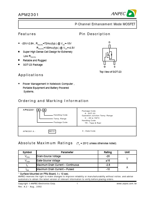
ANPEC reserves the right to make changes to improve reliability or manufacturability without notice, and advise customers to obtain the latest version of relevant information to verify before placing orders.Pin DescriptionOrdering and Marking InformationFeaturesApplicationsAbsolute Maximum Ratings (T A = 25°C unless otherwise noted)• -20V/-2.8A , R DS(ON)=72m Ω(typ.) @ V GS =-10VR DS(ON)=100m Ω(typ.) @ V GS =-4.5V• Super High Dense Cell Design for ExtremelyLow R DS(ON)• Reliable and Rugged • SOT-23 Package• Power Management in Notebook Computer ,Portable Equipment and Battery Powered Systems.* Surface Mounted on FR4 Board, t ≤ 10 sec.G DSTop View of SOT-23Notesa : Pulse test ; pulse width ≤300µs, duty cycle ≤ 2%b: Guaranteed by design, not subject to production testingAbsolute Maximum Ratings Cont. (T A = 25°C unless otherwise noted)Electrical Characteristics (T A = 25°C unless otherwise noted)2468100.0300.0450.0600.0750.0900.1050.1200.1350.150012345246810-50-2502550751001251500.000.250.500.751.001.251.500.00.5 1.0 1.5 2.0 2.50246810Typical Characteristics-I D -D r a i n C u r r e n t (A )Transfer Characteristics-V GS - Gate-to-Source Voltage (V)Threshold Voltage vs. Junction T emperatureTj - Junction T emperature (°C)-V G S (t h )-T h r e s h o l d V o l t a g e (V )(N o r m a l i z e d )R D S (O N )-O n -R e s i s t a n c e (Ω)On-Resistance vs. Drain Current-I D - Drain Current (A)Output Characteristics-I D -D r a i n C u r r e n t (A )-V DS - Drain-to-Source Voltage (V)369121505101520-50-25025507510012515012345678910Typical CharacteristicsR D S (O N )-O n -R e s i s t a n c e (Ω)(N o r m a l i z e d )On-Resistance vs. Junction TemperatureT J - Junction Temperature (°C)-V DS - Drain-to-Source Voltage (V)CapacitanceC a p a c i t a n c e (p F )-V GS - Gate-to-Source Voltage (V)R D S (O N )-O n -R e s i s t a n c e (Ω)On-Resistance vs. Gate-to-Source VoltageGate ChargeQ G - Gate Charge (nC)-V G S -G a t e -S o u r c e V o l t a g e (V )0.00.20.40.60.8 1.0 1.2 1.4 1.61100.010.1110100024681012141E-41E-30.010.11101000.010.11Typical CharacteristicsP o w e r (W )Single Pulse PowerTime (sec)Square Wave Pulse Duration (sec)Source-Drain Diode Forward Voltage-I S -S o u r c e C u r r e n t (A )-V SD -Source-to-Drain Voltage (V)N o r m a l i z e d E f f e c t i v e T r a n s i e n t T h e r m a l I m p e d a n c eNormalized Thermal Transient Impedence, Junction to AmbientPackaging Information SOT-23Physical SpecificationsReflow Condition (IR/Convection or VPR Reflow)Reference JEDEC Standard J-STD-020A APRIL 1999Classification Reflow ProfilesPackage Reflow ConditionsPre-heat temperature183 CPeak temperatureTime°t e m p e r a t u r eReliability test programCarrier Tape & Reel DimensionsCover Tape DimensionsCustomer ServiceAnpec Electronics Corp.Head Office :5F, No. 2 Li-Hsin Road, SBIP,Hsin-Chu, T aiwan, R.O.C.T el : 886-3-5642000Fax : 886-3-5642050Taipei Branch :7F, No. 137, Lane 235, Pac Chiao Rd.,Hsin Tien City, Taipei Hsien, T aiwan, R. O. C.T el : 886-2-89191368Fax : 886-2-89191369。
2301导通电压 -回复
2301导通电压-回复什么是2301导通电压?导通电压是指在电子元件或电路中,当某个特定条件满足时,电流可以自由地流经的最低电压值。
而2301导通电压是指在2301(或2N301)型号的晶体管中,电流开始流动的最小电压值。
晶体管是一种重要的电子器件,可用于放大电信号、开关电路和调节电流等应用。
2301型号是一种常见的NPN型晶体管,广泛应用于各种电子设备和电路中。
对于一个晶体管,其基本构造包括一个基极、一个发射极和一个集电极。
当电压施加在基极-发射极之间时,通过调节基极电流,可以控制电流是否能从集电极流过。
而2301导通电压则是指在满足一定条件下,使得晶体管导通所需的最低电压。
那么,2301导通电压的具体数值是多少?当两个引脚之间施加一个足够大的电压,通常在0.7-0.8伏之间,基极和发射极之间的结就可以变得导电,电流开始流动。
这个电压被称为2301导通电压。
为了更好地理解2301导通电压的作用,我们可以通过一个简单的电路来说明。
假设有一个用2301晶体管驱动的LED灯电路。
在这个电路中,晶体管的基极通过一个限流电阻与正极相连接,而发射极与负极相连接。
当控制电压施加在基极与负极之间时,如果电压大于2301导通电压,晶体管就会导通,电流通过发射极流向负极,从而点亮LED灯。
在这个例子中,2301导通电压的重要性显而易见。
如果导通电压过高,例如超过了2301寄生二极管的初始压降,那么实际上导通电流并不会得到控制,电路可能会失去正常的工作状态。
同样,如果导通电压过低,晶体管可能无法导通,无法提供所需的电流供应。
因此,2301导通电压是确保晶体管正常工作的重要参数之一。
除了2301导通电压外,还有其他影响晶体管导通的因素,例如环境温度、晶体管的封装形式和质量等。
因此,在实际应用中,除了要了解2301导通电压的数值,还需要综合考虑其他因素,以确保晶体管的可靠工作。
总结起来,2301导通电压是指在2301型号的晶体管中,电流开始流动的最小电压值。
SAE AMS 2301-2001- 中文
端要首先磁化检验,较大的台阶要分别单独磁化并检验直到所有的台阶都检验完。如果
板状的用的是长薄片(如 3.1.3.5),只检验长薄片的两个面
3.2.1 清洁度标准主要要检验非金属夹杂物(见 8.3),除了样品制作过程中造成的裂缝重叠
等缺陷外,其余的裂纹等缺陷会被拒收
3.2.2 磁粉探伤检验要做记录,记录填写后,买方可要求查看
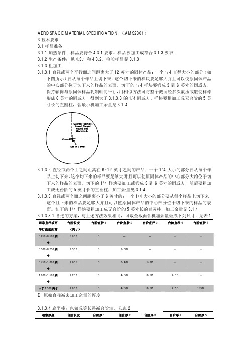
3.1.3.2 直径或两个面之间距离在 6~12 英寸之间的产品:一个 1/4 大小的部分要从每个样 品上切下来,这个切下来的样品要足够大并且可以使原固体产品的中心部分大约位于切
下来的样品的表面。切下的 1/4 样块要加工或锻成 3 到 6 英寸的圆或方,随后要粗加 工成无台阶的 5 英寸长的直圆柱,加工余量见 3.1.4 3.1.3.3 直径或两个面之间距离小于 6 英寸的:一个 1/4 大小的部分要从每个样品上切下来, 这个且下来的样品要足够大并且可以使原固体产品的中心部分位于切下来的样品的表
T
T=原始通常减去加工余量的厚度
--
--
--
--
2/3T
--
--
--
3/4T
1/2T
1/4T
--
4/5T
3/5T
2/5T
1/5T
3.1.3.5 厚板或平板:要加工一个直圆柱或矩形,或者锻造后加工,样棒要从滚压的平行方 向取,要位于板宽的中心到边缘的中部,大约 5 英寸长,不大于 4 英寸直径或厚度。
含碳量(%)
频次等级
小于 0.25
0.37
大于等于 0.25
0.34
严重性等级 0.28 0.25
3.4.1.2 板类的符合表 8 频次等级(同一 热处理) 0.80
(完整word版)AM2301温湿度传感器模块
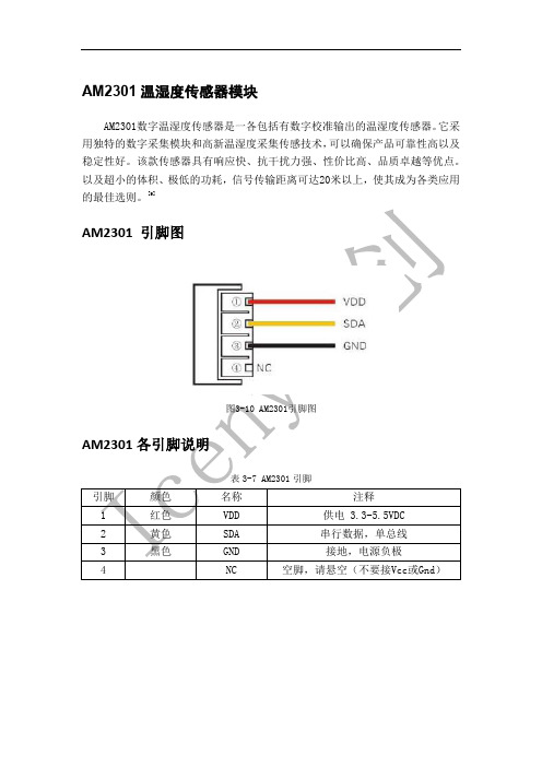
AM2301温湿度传感器模块AM2301数字温湿度传感器是一各包括有数字校准输出的温湿度传感器。
它采用独特的数字采集模块和高新温湿度采集传感技术,可以确保产品可靠性高以及稳定性好。
该款传感器具有响应快、抗干扰力强、性价比高、品质卓越等优点。
以及超小的体积、极低的功耗,信号传输距离可达20米以上,使其成为各类应用的最佳选则。
[9]AM2301 引脚图图3-10 AM2301引脚图AM2301各引脚说明表3-7 AM2301引脚引脚颜色名称注释1 红色VDD 供电 3.3-5.5VDC2 黄色SDA 串行数据,单总线3 黑色GND 接地,电源负极4 NC 空脚,请悬空(不要接Vcc或Gnd)AM2301 技术参数表3-8 AM2301技术参数参数条件Min Typ Max 单位湿度分辨率0.1 %RH16 Bit重复性±1 %RH 精度25℃±3 %RH 0-50℃±5 %RH 互换性可完全互换采样周期 1 2 S2 S响应时间1/e(63%)25℃,1m/s 空气迟滞±0.3 %RH 长期稳定性典型值±1 %RH/yr温度分辨率0.1 ℃16 Bit重复性±0.5 ℃精度±1 ℃量程范围-40 80 ℃响应时间1/e(63%) 6 20 S AM2301 驱动电路图3-11 AM2301驱动电路图温湿度传感器模块流程设计用户主机(MCU)发送一次开始信号后,AM2301自动从休眠模式转换到高速模式。
等待主机开始,信号发送后,AM2301发送响应信号,送出40比特的数据,发送数据结束之后触发一次信号采集,对外部环境进行数据采集,采集结束传感器自动转入休眠模式,直到下一次通信信号的来临。
此时AM2301的SDA数据线由上拉电阻拉高,一直保持高电平,且AM2301的SDA引脚处于输入状态,时刻检测外部图4-10温湿度传感器流程图1602 LCD显示屏测试根据第三章说明的LCD硬件连线要求,将屏幕的14个接口按要求分别连接至单片机的各端口,确认无误后,个单片机上电,并将编完的程序通过STC-ISP 软件烧入到单片机中,连线图如下:图5-3 LCD1602连线图给单片机上电之后,屏幕显示如下:图5-4 LCD1602显示效果该LCD显示屏能正常显示预期设置字幕。
航空航天原材料明细表
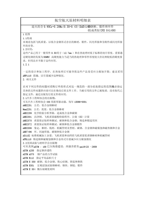
航空航天原材料明细表的钢棒,锻件和环件 退火的含0.95Cr-0.20Mo(0.38-0.43)(SAE4140)(组成类似UNS G41400)1范围1.1组成本规范包括飞机质量,以低合金钢形式存在的棒材,锻件,闪光焊接和为铸件或闪光焊接环的存货。
1.2应用:这些产品已用于一般零件0.50英寸(12.7mm)和在热处理时低于标准的切片厚度,需要通过硬化钢的发展为50HRC高硬度能力当适当的热处理和零件厚度较大但比例较低的硬度要求,但用法并不限于这些应用。
1.2.1一定的设计和加工程序,在热处理后可能导致这些产品易受应力腐蚀开裂;建议采用ARP1110措施,以尽量减少这种情况。
2. 相关文件在对下列文件的问题对采购订单的形式对这一规范的一部分此处指定的范围内,除非指定具体的文件问题供应商可以在修改后的文件工作。
当被引用的文件已被取消,没有取代已指定文件,最近出版发行的文件将应用。
2.1汽车工程师协会的出版物:可从汽车工程师协会400英联邦驱动器,每年15096-0001AMS2251公差,低合金钢棒材Mam2251公差,度量,低合金钢棒材AMS2259化学检验分析界限,造成低合金和碳钢AMS2301洁净钢,飞机质量磁粉检验程序,公制(SI)计量AMS2370质量保证取样和测试,碳钢和低合金钢,铸造和锻造用坯AMS2372质量保证取样和测试,碳钢和低合金钢锻件AMS2806鉴定,棒材,线材,机械管材及型材,碳钢,合金钢和耐腐蚀和耐热钢和合金 AMS7496环,闪速焊接,碳钢和低合金钢AS1182标准机械加工余量,飞机质量和高档的飞机质量优质钢棒材和机械管材APR1110铸造钢和耐腐蚀钢和合金形式尽量减少应力腐蚀裂纹2.2美国试验与材料学会出版物可从美国ASTM,100巴尔海港建设,西康舍霍肯,pa19428 – 2959ASTM A255指定钢淬透性ASTM A370 钢产品的力学试验ASTM E112指定平均晶粒尺寸ASTM E 350碳钢,低合金钢,铁心硅钢,铁锭和熟铁ASTM E381 宏观浸蚀试验钢棒材,钢坯,钢锭,锻件ASTM E 384微压痕硬度材料AMS6382M 汽车工程师协会 AMS6382M3. 技术要求3.1组成:应符合表1所显示的百分比重,湿化学方法测定按照与ASTM350, 通过光谱化学方法或买方接受的其他分析方法:表1-组成元素 min max炭 0.38 0.43锰 0.75 1.00硅 0.15 0.35磷 -- 0.025硫 -- 0.025铬 0.80 1.10钼 0.15 0.25镍 -- 0.25铜 -- 0.353.1.1检查分析:成分的变化,应当符合AMS2259的适用要求3.2条件:该产品应提供在后续条件 ;硬度和拉伸强度应按照确定的ASTMA370:3.2.1棒材:英寸(12.70mm)棒材和根据公称直径或至少平行双方之间的距离:3.2.1.1 0.500退火和冷处理后拉伸强度不高于125 KSI(862MPa)或同等硬度(见8.2)3.2.1.2 公称直径超过0.500英寸(12.70mm)的棒材或至少平行双方之间的距离:热退火完成,除非另有命令,具有硬度不大于229HB,或等同(见8.3)。
AMS电源芯片产品介绍

AMS3132,3A 低压差稳压器
输入电压范围:1.5-7V 输出电压固定或可调 最低输出0.6V每100mV一个步进 最大输出电流:3A 压差:700mV@3A 125uA典型供电电流 关断模式静态电流小于25uA 静噪:-85dB@100HZ 可选功能:电源状态指示(PG) EN功能较:可控制芯片输出关断 限流保护 过温保护 工作温度:-40 ~ 125℃ 封装:TO-263 5L
AMS3132M
MIC29302
AMS3120
SC4215
封装和引脚定义都相同。但是内部基准电压不同,在可调版本替换的 时候,需要修改外部电压调节电阻的电压
AMS3121
MIC29150
可以直接替代。由于都只有固定电压的版本。所以要根据客户使用的 型号再申请样片
AMS3131
MIC29300
可以直接替代。由于都只有固定电压的版本。所以要根据客户使用的 型号再申请样片
so8edp8ams415328v3a降压稳压器立体眼镜方案左眼镜片右眼镜片单片机纽扣电池或者锂电ldoams6104镜片开关镜片开关红外头接收同步型号ams6104用于将电池的3v升到10v给镜片供电
AMS产品介绍
李增勇制作
AMS主推产品型号
超低低压差LDO AMS3106,AMS3120,AMS3122,AMS3132 普通LDO AMS1117,AMS108X 降压DC-DC AMS2538,AMS2596,AMS4123 升压DC-DC AMS6101、 AMS6104
Vin 4.5V to 20V C1 10uF C3 2.2uF C D
U1 3 2.5V 7 LDOin Vin
AMS4123 SW 1
AM2301最新说明书 传感器模块

数字温湿度传感器AM2301►相对湿度和温度测量►全部校准,数字输出►卓越的长期稳定性►无需额外部件►超长的信号传输距离►超低能耗►4 引脚安装►完全互换AM2301产品概述AM2301数字温湿度传感器是一款含有已校准数字信号输出的温湿度复合传感器。
它应用专用的数字模块采集技术和温湿度传感技术,确保产品具有极高的可靠性与卓越的长期稳定性。
传感器包括一个电容式感湿元件和一个NTC 测温元件,并与一个高性能8位单片机相连接。
因此该产品具有品质卓越、超快响应、抗干扰能力强、性价比极高等优点。
每个AM2301传感器都在极为精确的湿度校验室中进行校准。
校准系数以程序的形式储存在OTP内存中,传感器内部在检测信号的处理过程中要调用这些校准系数。
单线制串行接口,使系统集成变得简易快捷。
超小的体积、极低的功耗,信号传输距离可达20米以上,使其成为各类应用甚至最为苛刻的应用场合的最佳选则。
产品为 4 针单排引脚封装。
连接方便,特殊封装形式可根据用户需求而提供。
应用领域►暖通空调►测试及检测设备►汽车►数据记录器►消费品►自动控制►气象站►家电►湿度调节器►医疗►除湿器1、传感器性能说明参数条件Min Typ Max 单位湿度分辨率0.1 %RH16 Bit 重复性±1 %RH 精度25℃±3 %RH 0-50℃±5 %RH 互换性可完全互换采样周期 1 2 S响应时间1/e(63%)25℃,2 S1m/s 空气迟滞±0.3 %RH 长期稳定性典型值±1 %RH/yr 温度分辨率0.1 ℃16 Bit 重复性±0.5 ℃精度±1 ℃量程范围-40 80 ℃响应时间1/e(63%) 6 20 S2、采样周期不得低于最小值,否则会引起错误3、接口说明建议连接线长度短于20米时用5K上拉电阻,大于20米时根据实际情况使用合适的上拉电阻3、电源引脚AM2301的供电电压为5V。
Burkert产品型号2301、2300、2103和2702的数字电动定位器说明书
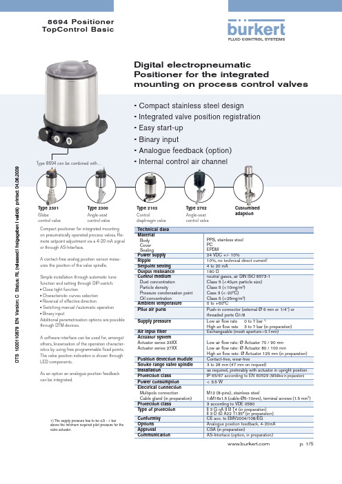
8694 Positioner TopControl BasicType 2301Globecontrol valveType 2300Angle-seat control valveType 2103Controldiaphragm valveType 2702Angle-seatcontrol valveCustomisedadaptionDigital electropneumaticPositioner for the integratedmounting on process control valvesCompact positioner for integrated mounting on pneumatically operated process valves. Re-mote setpoint adjustment via a 4-20 mA signal or through AS-Interface.A contact-free analog position sensor meas-ures the position of the valve spindle.Simple installation through automatic tune function and setting through DIP-switch:• Close tight function• Characteristic curves selection • Reversal of effective direction• Switching manual /automatic operation • Binary inputAdditional parametrisation options are possible through DTM devices.A software interface can be used for, amongst others, linearisation of the operation character-istics by using free programmable fi xed points. The valve position indication is shown through LED components.As an option an analogue position feedback can be integrated.Type 8694 can be combined with…• Compact stainless steel design• Integrated valve position registration • E asy start-up• Binary input• Analogue feedback (option) • Internal control air channelTechnical data Material Body Cover SealingPPS, stainless steel PC EPDMPower supply 24 VDC +/- 10%Ripple10%, no technical direct current!Setpoint setting 4 to 20 mA Output resistance 180 ΩControl medium Dust concentration Particle densityPressure condensation point Oil concentrationneutral gases, air DIN ISO 8573-1Class 5 (<40μm particle size)Class 5 (<10mg/m 3)Cass 3 (<-20°C)Class 5 (<25mg/m 3)Ambient temperature 0 to +60°CPilot air ports Push-in connector (external Ø 6 mm or 1/4") or threaded ports G1/8Supply pressure Low air fl ow rate 0 to 7 bar 1)High air fl ow rate 3 to 7 bar (in preparation)Air input fi lter Exchangeable (mesh aperture~0.1mm)Actuator system Actuator series 23XX Actuator series 27XX Low air fl ow rate: Ø Actuator 70 / 90 mm Low air fl ow rate: Ø Actuator 80 / 100 mm High air fl ow rate: Ø Actuator 125 mm (in preparation)Position detection module Contact-free, wear-freeStroke range valve spindle 3 to 28 mm (47 mm on request)Installationas required, preferably with actuator in upright position Protection class IP 65/67 according to EN 60529 (NEMA4x in preparation)Power consumption < 3.5 WElectrical connection Multipole connectionCable gland (in preparation)M12 (8-pins), stainless steel1xM16x1.5 (cable-Ø5-10mm), terminal screws (1.5 mm 2) Protection class 3 according to VDE 0580Type of protection II 3 G nA II B T4 (in preparation)II 3 D tD A22 T135° (in preparation)Conformity CE acc. to EMV2004/108/EGOptions Analogue position feedback, 4-20mA ApprovalCSA (in preparation)CommunicationAS-Interface (option, in preparation)1) The supply pressure has to be 0,5 - 1 barabove the minimum required pilot pressure for the valve actuator.Ordering information for TopControl-Control valve systemsA complete TopControl-Control valve system consists of a TopControl Basic Type 8694 and a process valve Type 23XX or 27XX . The following information is necessary for the selection of a complete control valve:•Item no. of the Positioner TopControl Basic Type 8694 without process valve, see ordering chart on p. 3•Item no. of the desired process valve Type 23XX or 27XX (see separate datasheets, e.g. 2300, 2301 or 2702, 2712, 2730)•Note: TopControl-Control valve systemWhen you click on the orange box "More info." below, you will come to our website for the resp. product where you can download the datasheet.Valve systemContinuous Classic Type 8802-YC-L 2702 + 86942301 2300 2702 Globe control Angle-seat Angle-seat valve control valve control valve-I -I Valve systemContinuous ELEMENT Type 8802-YG-L 2300 + 8694Ordering chart Type 8694(other versions on request)Ordering chart accessoriesApprovals CSA&URTHERôVERSIONSôONôREQUESTOrdering chart adapter kit(has to be ordered separately)in preparationin preparationDimensions [mm]Mounting on process valve Type 27xxMaterials1Cover PC2Body casing Stainless steel 3Basic body PPS4Plug M12 Stainless steel 5ScrewsStainless steel 6Push-in connector Threaded ports G1/8POM/stainless steel Stainless steel 7SealingEPDMSignal flow diagram Position control loopTopControl Basic functions• Automatic start of the control system• Linear or progressive characteristic curvesselection (DIP-switch); free programmableover Software interface• Close tight function• Reversal of effective direction of the setpointsignal• Switching manual / automatic operation• Binary input (controller enable)• Parametrisation of the device through DTM Schematic diagram of the TopControl Basic1) The operating voltage is supplied with a 3-wire unit independent from the setpoint signal.Connection optionsConnection MultipoleTo fi nd your nearest Bürkert facility, click on the orange box In case of special application conditions,please consult for advice.Subject to alteration.© Christian Bürkert GmbH & Co. KG0906/3_EU-en_00895044。
2865-SAE_AMS2301
__________________________________________________________________________________________________________________________________________ SAE Technical Standards Board Rules provide that: “This report is published by SAE to advance the state of technical and engineering sciences. The use of this report is entirely voluntary, and its applicability and suitability for any particular use, including any patent infringement arising therefrom, is the sole responsibility of the user.”SAE reviews each technical report at least every five years at which time it may be revised, reaffirmed, stabilized, or cancelled. SAE invites your written comments and suggestions.Copyright © 2015 SAE InternationalAll rights reserved. No part of this publication may be reproduced, stored in a retrieval system or transmitted, in any form or by any means, electronic, mechanical, photocopying, recording, or otherwise, without the prior written permission of SAE.TO PLACE A DOCUMENT ORDER: Tel: 877-606-7323 (inside USA and Canada)Tel: +1 724-776-4970 (outside USA) SAE values your input. To provide feedback on this Technical Report, please visit AEROSPACEMATERIAL SPECIFICATIONAMS2301REV. KIssued 1960-01 Revised 2010-08 Reaffirmed 2015-05Superseding AMS2301JSteel Cleanliness, Aircraft Quality Magnetic Particle Inspection ProcedureRATIONALEAMS2301K has been reaffirmed to comply with the SAE five-year review policy.1. SCOPE 1.1 PurposeThis specification covers steel cleanliness requirements in inch/pound units for aircraft-quality ferro-magnetic steels, other than hardenable corrosion resistant steels (See AMS2303), by magnetic particle inspection methods. This specification contains sampling, specimen preparation, inspection procedures and cleanliness rating criteria (See 8.5). 1.1.1The metric version, MAM2301, has been cancelled. The SI units have been included in this specification, but the inch/pound units are primary (See 8.5).1.2 ApplicationThis procedure has been used typically for the cleanliness evaluation of blooms, billets, tube rounds, stock for forging or flash welded rings, slabs, bars, sheet, strip, plate, tubing, and extrusions used in fabricating parts subject to magnetic particle inspection, but may be used for qualification of a heat, melt, or lot of steel. 2. APPLICABLE DOCUMENTSThe issue of the following documents in effect on the date of the purchase order forms a part of this specification to the extent specified herein. The supplier may work to a subsequent revision of a document unless a specific document issue is specified. When the referenced document has been cancelled and no superseding document has been specified, the last published issue of that document shall apply. 2.1 ASTM PublicationsAvailable from ASTM International, 100 Barr Harbor Drive, P.O. Box C700, West Conshohocken, PA 19428-2959, Tel: 610-832-9585, . ASTM E 10Brinell Hardness of Metallic MaterialsASTM E 1444 Magnetic Particle Testing--``,``,,,``,```,```,,`-`-``,```,,,`---2.2 ANSI PublicationsAvailable from American National Standards Institute, 25 West 43rd Street, New York, NY 10036-8002, Tel: 212-642-4900, . ANSI B46.1Surface Texture3. TECHNICAL REQUIREMENTS 3.1 Specimen Preparation 3.1.1 Heat QualificationSampling shall be in accordance with 4.3.1. Samples shall be converted into test specimens in accordance with 3.1.3. 3.1.2 Product QualificationProduct from a heat not qualified based on sampling as in 4.3.1 shall be sampled in accordance with 4.3.2. Samples shall be converted into test specimens in accordance with 3.1.3. 3.1.3 Working and Rough Machining3.1.3.1Solid Product 12 Inches (305 mm) and Over in Nominal Diameter or Distance Between Parallel SidesA quarter-section shall be cut from each sample sufficiently oversized that the center of the original sample will be approximately on the surface of the specimen after generating to test size. The quarter-section shall then be forged to a 3 to 6 inch (76 to 152 mm) round or square, maintaining the axis of the forging approximately parallel to the original direction of rolling. As an alternate method, the full section may be rolled or forged to a 6-inch (152-mm) round or square and an oversize quarter obtained as in 3.1.3.3. Specimens shall be rough machined to a “one-step” straight cylinder nominally 5 inches (127 mm) long. Minimum stock removal shall be consistent with the machining allowance specified in 3.1.4.3.1.3.2 Solid Product Over 6 to 12 Inches (152 to 305 mm), Exclusive, in Nominal Diameter or Distance BetweenParallel Sides Except Slabs and Plates A quarter-section shall be cut from each sample sufficiently oversize that the center of the original sample will be approximately on the surface of the specimen after generating to test size. The quarter-section shall be converted into a test specimen by machining, or forging and machining, to a 3 to 6 (76 to 152 mm) inch round or square. Specimens shall be rough machined to a “one-step” straight cylinder nominally 5 inches (127 mm) long. Minimum stock removal shall be consistent with the machining allowance specified in 3.1.4. 3.1.3.3Solid Product 6 Inches (152 mm) and Under in Nominal Diameter or Distance Between Parallel Sides Except Flat Bars, Slabs, and PlatesA quarter-section shall be cut from each sample sufficiently oversize that the center of the original sample will be approximately on the surface of the specimen after generating to test size. The quarter-section shall be converted into a test specimen by machining to a “one-step” straight cylinder nominally 5 inches (127 mm) long. Minimum stock removal shall be consistent with the machining allowance specified in 3.1.4. 3.1.3.3.1As an alternate method, a step-down specimen may be generated from the full cross-section in equal length circumferential steps as shown in Table 1, consistent with the machining allowance specified in 3.1.4.SAE INTERNATIONAL AMS2301K Page 2 of 14_________________________________________________________________________________________________ --``,``,,,``,```,```,,`-`-``,```,,,`---TABLE 1A - STEPDOWN SPECIMENS, CYLINDRICAL, INCH/POUND UNITSNominalDiameter or Distance Between Parallel SidesInches Step Length InchesStep 1 Diameter Step 2 DiameterStep 3 DiameterStep 4 DiameterStep 5 Diameter0.250 to 0.500, incl 5.000 D -- -- -- -- Over 0.500 to 0.750, incl 2.500 D 2/3D -- -- -- Over 0.750 to 1.000, incl1.665 D3/4D1/2D----Over 1.000 to 1.500, incl 1.250 D 4/5D 3/5D 2/5D -- Over 1.500 1.000 D 4/5D 3/5D 2/5D 1/5D D = Original diameter or distance between parallel sides minus machining stock removed.TABLE 1B - STEPDOWN SPECIMENS, CYLINDRICAL, SI UNITSNominalDiameter or Distance Between Parallel SidesMillimeters StepLength Millimeters Step 1 DiameterStep 2 Diameter Step 3 Diameter Step 4 Diameter Step 5 Diameter6.35 to 12.70, incl 127.00 D -- -- -- --Over 12.70 to 19.05, incl 63.50 D 2/3D ------ Over 19.05 to 25.40, incl 42.29 D 3/4D 1/2D ----Over 25.40 to 38.10, incl31.75 D 4/5D 3/5D 2/5D --Over 38.10 25.40 D 4/5D 3/5D 2/5D 1/5D D = Original diameter or distance between parallel sides minus machining stock removed. 3.1.3.4 Flat BarsThe type of test and the location in the section shall be as agreed upon by purchaser and vendor. A step-down specimen may be generated from the full cross-section in equal length steps as shown in Table 2.TABLE 2A - STEPDOWN SPECIMENS, FLAT BAR, (INCH/POUND UNITS)Nominal Thickness InchesStepLength InchesStep 1 Thickness Step 2 Thickness Step 3 Thickness Step 4 Thickness Step 5 ThicknessUp to 0.250, incl5.000 T -- -- -- -- Over 0.250 to 0.500, incl 2.500 T 2/3T -- -- -- Over 0.500 t o 1.000, incl1.250T3/4T1/2T1/4T-- Over 1.0001.000 T4/5T 3/5T 2/5T1/5TT = Original nominal thickness minus machining stock removed.SAE INTERNATIONAL AMS2301K Page 3 of 14_________________________________________________________________________________________________ --``,``,,,``,```,```,,`-`-``,```,,,`---TABLE 2B - STEPDOWN SPECIMENS, FLAT BAR (SI UNITS)Nominal Thickness MillimetersStepLengthMillimetersStep 1ThicknessStep 2ThicknessStep 3ThicknessStep 4ThicknessStep 5ThicknessUp to 6.35, incl 127.00 T -- -- -- --Over 6.35 to 12.70, incl 63.50 T 2/3T -- -- --Over 12.70 to 25.40, incl 31.75 T 3/4T 1/2T 1/4T -- Over 25.40 25.40 T 4/5T 3/5T 2/5T 1/5TT = Original nominal thickness minus machining stock removed.3.1.3.5 Slabs or PlatesA straight cylindrical or rectangular specimen shall be machined, or forged and machined, from each slab or plate tested. The specimen shall be taken essentially parallel to the direction of rolling, midway between edge and center of the slab or plate width, shall be nominally 5 inches (127 mm) in length, and shall be not more than 4 inches (102 mm) in final diameter or thickness.3.1.3.5.1 Product Up to 4 Inches (102 mm), Inclusive, in Nominal ThicknessA straight cylindrical specimen shall represent the full thickness consistent with the machining allowance specified in 3.1.4.3.3.1.3.5.2 Product Over 4 to 8 Inches (102 to 203 mm), Inclusive, in Nominal ThicknessA straight cylindrical specimen shall represent surface to mid-thickness consistent with the machining allowance specified in 3.1.4.3.3.1.3.5.3 Product Over 8 Inches (203 mm) in Nominal ThicknessA straight cylindrical specimen shall be taken so that the axis is approximately midway between the surface and mid-thickness, and shall have a diameter equal to one-third the nominal thickness of the section, allowing 0.010 inch (0.25mm) per side for finish machining after heat treatment.3.1.3.6 Tubing3.1.3.6.1 10 inches (254 mm) and Under in Nominal ODSpecimens nominally 5 inches (127 mm) in length shall be machined to straight cylindrical sections in accordance with 3.1.4.2.1.3.1.3.6.2 Over 10 Inches (254 mm) in Nominal OD with Nominal Wall Thickness Up to 2 Inches (51 mm), Inclusive Specimens nominally 5 inches (127 mm) in length shall be machined to straight cylindrical sections in accordance with 3.1.4.2.2.3.1.3.6.3 Over 10 Inches (254 mm) in Nominal OD with Nominal Wall Thickness Over 2 to 4 Inches (51 to 102 mm),InclusiveSpecimens nominally 5 inches (127 mm) in length representing the full cross-section, less the machining allowancespecified in 3.1.4.2.2, shall be machined to straight cylindrical sections.--``,``,,,``,```,```,,`-`-``,```,,,`---3.1.3.6.4Over 10 Inches (254 mm) in Nominal OD with Nominal Wall Thickness Over 4 Inches (102 mm)Specimens nominally 5 inches (127 mm) in length, representing the inside surface to the mid-thickness of the wall, less the machining allowance specified in 3.1.4.2.2, shall be machined to straight cylindrical sections. 3.1.4 Machining 3.1.4.1Product Other Than Tubing, Flat Bars, and Slab and Plates Over 8 Inches (203 mm) ThickThe converted sample shall be machined to conform to the allowance shown in Table 3 for surface removal, allowing 0.010 inch (0.25 mm) on each side for finish machining after heat treatment.TABLE 3 - STOCK REMOVALNominalDiameter or Distance Between Parallel Sides Inches (Millimeters)MinimumStock RemovalInch (Millimeters) per Side0.250 to 0.500 (6.35 to 12.70), incl 0.030 (0.76) Over 0.500 t o 0.750 (12.70 to 19.01), incl 0.045 (1.14) Over 0.750 to 1.000 (19.01 to 25.40), incl 0.060 (1.52) Over 1.000 to 1.500 (25.40 to 38.10), incl 0.075 (1.91) Over 1.500 to 2.000 (38.10 to 50.80), incl 0.090 (2.29) Over 2.000 to 2.500 (50.80 to 63.50), incl 0.125 (3.18) Over 2.500 to 3.500 (63.50 to 88.90), incl 0.156 (3.96) Over 3.500 to 4.500 (88.90 to 114.30), incl 0.187 (4.75) Over 4.500 to 6.000 (114.30 to 152.40), incl0.250 (6.35)3.1.4.2 Tubing 3.1.4.2.110 Inches and Under in Nominal ODTubing with nominal wall thickness under 0.250 inch (6.35 mm) shall have 10% of the wall thickness or 0.015 inch (0.38 mm), whichever is less, removed from the OD after heat treatment. Samples from tubing with nominal wall thickness of 0.250 inch and over shall be machined to conform to the stock removal requirement shown in Table 4.TABLE 4 - STOCK REMOVALMachined Diameter Inches(Millimeters)Minimum Stock RemovalInch (Millimeters) per SideUp to 2-1/2 (63.5), incl 0.044 (1.12) Over 2-1/2to 3-1/2 (63.5 to 88.9), incl 0.046 (1.17) Over 3-1/2 to 4-1/2 (88.9 to 114.3),incl0.052 (1.32)Over 4-1/2 to 5-1/2 (114.3 to 139.7), i ncl 0.057 (1.45) Over 5-1/2 to 6-1/2 (139.7 to 165.1), i ncl 0.064 (1.63) Over 6-1/2 to 8 (165.1 to 203.2), incl0.074 (1.88)Over 8 to 10 (203.2 to 254.0), i ncl 0.087 (2.21)--``,``,,,``,```,```,,`-`-``,```,,,`---3.1.4.2.2 Tubing Over 10 Inches (254 mm) in Nominal ODTubing 4 inches (102 mm) and under in nominal wall thickness shall be turned to straight cylindrical sections representing the full cross-section of the wall, less allowance of 0.150 inch (0.38 mm) stock removal on the OD and ID and allowing 0.010 inch (0.25 mm) on each side for finish machining after heat treatment. Samples from tubing with nominal wall thickness over 4 inches (102 mm) shall be turned to cylindrical sections representing the cross section from the OD to mid-thickness of the wall less allowance of 0.150 inch (0.38 mm) stock removal on the OD, and allowing 0.010 inch (0.25 mm) on each side for finish machining after heat treatment.3.1.4.3 Flat Bars, Slabs, and PlatesAllowance of 20% of the nominal thickness or 0.100 inch (2.54 mm), whichever is less, shall be made for minimum stock removal, allowing 0.010 inch (0.25 mm) on each side for finish machining after heat treatment.Treatment3.1.5 HeatRough machined specimens shall, if necessary, be heat treated by suitable austenitizing, quenching, and tempering or by solution and precipitation heat treating to produce hardness of 248 to 352 HB or appropriate lower hardness for steel of low hardenability. Hardness testing shall be in accordance with ASTM E 10. Specimens shall be austenitized in a neutral or slightly reducing atmosphere. Following heat treatment, surface scale may be removed by grit blasting or another acceptable method.Machining3.1.6 FinishThe heat treated specimens shall be finished machined to surface texture not rougher than 40 microinches AA, determined in accordance with ANSI B46.1. Rateable surface of specimens shall be nominally 5 inches (127 mm) in length. The ends of the specimen shall be finished to provide good electrical contact.3.2 InspectionMagnetic particle testing shall be performed in accordance with ASTM E 1444 by the circular, wet, continuous method (See 8.3) using 800 to 1200 amperes per inch (32 to 48 amperes/mm) of diameter, or another magnetic particle procedure acceptable to purchser. If the stepdown bar (3.1.3.3.1 or 3.1.3.4) is used, the smallest step shall be magnetized and inspected first; the larger steps shall be magnetized and inspected individually in succession of increasing size until all steps have been evaluated. If a longitudinal slice from slab or plate, as in 3.1.3.5 is used, only the longitudinal surfaces perpendicular to the two faces of the slab or plate shall be inspected.3.2.1 Cleanliness standards presented herein govern nonmetallic inclusions only (See 8.3). Product that, duringinspection, reveals indications representing actual ruptures, such as cracks, seams, laminations, and laps, will be subject to rejection except where these defects result from sample preparation. If such indications are the consequence of sample preparation, a replacement retest sample may be obtained from material adjacent to the original test location.3.2.2 The results of the magnetic particle inspection shall be appropriately recorded. All recorded results shall beidentified, filed, and made available to purchaser upon request.3.3 Evaluation of Steel CleanlinessAfter inspection, each indication 1/16 inch (1.58 mm) and over in length shall be recorded. The frequency (number) and severity (size) of the indications shall be calculated as follows:--``,``,,,``,```,```,,`-`-``,```,,,`---3.3.1 Frequency(F)3.3.1.1 The number of indications per test specimen is totaled.3.3.1.2 The frequency rating of each specimen is determined by dividing the total number of indications for eachspecimen by the test surface area of the specimen in square inches (by dividing 6.45 times the total number of indications for each specimen by the test surface area of the specimen in square centimeters).3.3.2 The frequency ratings for all test specimens from a heat are totaled.3.3.2.1 The average frequency rating (F) equals the total frequency rating for all test specimens from a heat divided bythe number of test specimens.3.3.3 Severity(S)3.3.3.1 The length of each indication is recorded.3.3.3.2 The product for each specimen is computed by totaling the product of the number of indications times theappropriate progression factor shown in Table 5.TABLE 5 - PROGRESSION FACTOR FOR SEVERITY RATINGLength of Indication Inches(Millimeters) Progression Factor1/16 to 1/8 (1.59 to 3.18), incl 0.5 (3.2)Over 1/8 to 1/4 (3.18 to 6.35), incl 1 (6.5)Over 1/4 to 1/2 (6.35 to 12.70), incl 2 (13)Over 1/2 to 3/4 (12.70 to 19.05), incl 4 (26)Over 3/4 to 1 (19.05 to 25.40), incl 8 (52)Over 1 to 1-1/2 (25.40 to 38.10), incl 16 (103)3.3.3.2.1 Specimensthat contain indications representing nonmetallic inclusions over 1-1/2 inches (38.1 mm) in length shall be subject to rejection.3.3.3.3 The severity rating per specimen is determined by dividing the product for each specimen by the test surfacearea of the specimen in square inches (square centimeters).3.3.3.4 The severity ratings for all test specimens from a heat are totaled.3.3.3.5 The average severity (S) equals the total severity rating for all test specimens from a heat divided by thenumber of test specimens.3.4 DispositionProduct inspected in accordance with this specification shall conform to the following maximum frequency and severity ratings:3.4.1 HeatQualification (Reference 4.3.1)3.4.1.1 Product Other Than Slab, Sheet, Strip, and Plate3.4.1.1.1 Individual Test BarShall be as shown in Table 6.--``,``,,,``,```,```,,`-`-``,```,,,`---TABLE 6 - MAXIMUM FREQUENCY AND SEVERITY RATINGSCarbon Content Percent FrequencyRatingSeverityRatingUp to 0.25, excl 0.75 0.750.25 and over 0.67 0.553.4.1.1.2 Average of All Test Bars From a HeatShall be as shown in Table 7.TABLE 7 - MAXIMUM FREQUENCY AND SEVERITY RATINGSCarbon Content Percent FrequencyRatingSeverityRatingUp to 0.25, excl 0.37 0.280.25 and over 0.34 0.253.4.1.2 Slab and PlateShall be as shown in Table 8.TABLE 8 - MAXIMUM FREQUENCY AND SEVERITY RATINGSAverage of All Tests From a Heat FrequencyAverage of All Tests From a HeatSeverity0.80 0.67 3.4.2 Product Qualification (Reference 4.3.2)3.4.2.1 Product Other Than Sheet, Strip, and Plate3.4.2.1.1 Individual Test BarShall be as shown in Table 9.TABLE 9 - MAXIMUM FREQUENCY AND SEVERITY RATINGSProduct Nominal Diameter Inches (Millimeters) Carbon ContentPercentFrequencyRatingSeverityRatingUp to 2.500 (63.50), excl Up to 0.25, excl 1.10 1.050.25 and over 1.00 0.952.500 (63.50) and over Up to 0.25, excl 0.80 0.800.25 and over 0.80 0.67 --``,``,,,``,```,```,,`-`-``,```,,,`---3.4.2.1.2 Average of All Test Bars From a HeatShall be as shown in Table 10.TABLE 10 - MAXIMUM FREQUENCY AND SEVERITY RATINGSProduct Nominal DiameterInches Carbon ContentPercentFrequencyRatingSeverityRating1.000 to2.500 (25.40 to 63.50), incl Up to 0.25, excl 0.90 0.850.25 and over 0.85 0.80Over 2.500 to 4.000 (63.50 to 101.6), incl Up to 0.25, excl 0.60 0.550.25 and over 0.55 0.50Over 4.000 (101.6) Up to 0.25, excl 0.37 0.280.25 and over 0.34 0.253.4.2.1.2.1 Product under 1.000 inch (25.4) in nominal diameter or distance between parallel sides, inspected using thestraight cylindrical test bars or product under 16 square inches (103.2 square centimeters) in cross-sectional area, inspected by the alternate step-down specimen (3.1.3.3.1) shall have maximum averagefrequency and severity ratings agreed upon by purchaser and vendor.3.4.2.2 PlateShall conform to the ratings specified in 3.4.1.2.3.4.2.3 Sheet and StripShall have maximum individual and average frequency and severity ratings agreed upon by purchaser and vendor.3.4.3 Product inspected in accordance with this specification and having frequency or severity, or both, ratingsexceeding the specified limits may be reevaluated for specific applications when permitted by purchaser.Evaluation of any one or two steps of the alternate stepdown specimen may be waived by purchaser when the area represented is not considered critical for the end product.4. QUALITY ASSURANCE PROVISIONS4.1 Responsibility for InspectionThe vendor of the product shall supply all samples for vendor's tests and shall be responsible for the performance of all required tests. Purchaser reserves the right to sample and to perform any confirmatory testing deemed necessary to ensure that the product conforms to specified requirements.4.2 Classification of TestsAll applicable technical requirements are acceptance tests.4.2.1 HeatQualificationTests in accordance with 4.3.1, to determine conformance to "heat qualification" requirements, if acceptable, need be conducted only once on each heat.4.2.1.1 Heats that have been qualified as semi-finished product shall be considered qualified for finished product. --``,``,,,``,```,```,,`-`-``,```,,,`---4.2.2 Product QualificationTests on product not "heat qualified" shall be conducted on product of each size and shape of each lot made from each heat. 4.3Sampling and TestingThe sampling procedure for heat qualification as described in 4.3.1 shall be performed by the producer. No further sampling by the producer shall be required from a heat that meets the requirements of 3.4.1. Sampling procedure on product not “heat qualified” shall be as described in 4.3.2. 4.3.1 Heat Qualification 4.3.1.1Heats of Top-Poured IngotsSamples shall be taken from semi-finished or finished product representing the top and bottom of the first ingot and last usable ingot from heats having not more than 10 ingots, or not over 60 000 pounds (27 216 kilograms), or from portions of heats within these limits; and from the top and bottom of the first, middle, and last usable ingot of heats having more than 10 ingots or over 60 000 pounds (27 216 kilograms). 4.3.1.2Heats of Bottom-Poured IngotsSamples shall be taken from semi-finished or finished product representing the top and bottom of three ingots. One ingot shall be taken at random from the first usable plate poured, one ingot at random from the usable plate poured nearest to the middle of the heat, and one ingot at random from the last usable plate poured. When a heat consists of two usable plates, two of the sample ingots shall be selected from the second usable plate poured. When a heat consists of a single usable plate, any three random ingots may be selected. 4.3.1.2.1If there are less than three ingots in the heat, samples shall be taken representing the top and bottom of all ingots.4.3.1.3 Strand-Cast HeatsSamples shall be taken from semi-finished or finished product having at least a 3:1 reduction in cross-section from the cast strand, or samples of the as-cast strand similarly reduced, representing the front, middle, and back of both strands when two strands are cast, or of an inside strand and an outside strand when more than two strands are cast. When a single strand is cast, six samples having at least a 3:1 reduction from the cast strand, or samples of the cast strand similarly reduced, representing both ends of the first, middle, and last usable cuts (blooms) of the strand or product shall be taken.4.3.2 Product QualificationSamples shall be taken at random from not less than 10% of the pieces of each lot. A lot shall be all product of one size from one heat in one shipment. Not less than three nor more than ten samples shall be selected from a lot, except that if the quantity in the lot is three pieces or less, one sample shall be taken from each piece. 4.4 ReportsThe vendor of the product shall include the AMS2301K frequency-severity rating for each lot in the shipment in addition to other information required by the applicable material specification.--``,``,,,``,```,```,,`-`-``,```,,,`---4.5 Resampling and Retesting4.5.1 Product Other Than Slabs, Plates, Sheet, and StripIf any specimen used in the above tests fails to meet the specified requirements, disposition of the heat or lot may be based on the results of testing three additional specimens for each original nonconforming specimen; additional specimens shall be as follows:4.5.1.1 Heats of Top-Poured IngotsOne of the additional specimens shall be taken from the same position from product from each of the two available ingots most immediately adjacent in pouring sequence to where the originally nonconforming specimen was taken. The third specimen shall be taken from product of the original nonconforming ingot after additional discard. Should the latter specimen be unacceptable, resampling and retesting of the nonconforming ingot may be repeated after as many consecutive discards as necessary to obtain acceptable results. Should any of the adjacent ingot tests fail to meet specified requirements, resampling and retesting of these ingots will be permitted using the procedure specified for the original nonconforming ingot.4.5.1.2 Heats of Bottom-Poured IngotsOne of the additional specimens shall be taken from the same position from product from each of the two available ingots most immediately adjacent to where the originally nonconforming specimen was taken. The third specimen shall be taken from product of the original nonconforming ingot after additional discard. Should the latter specimen be unacceptable, resampling and retesting of the nonconforming ingot may be repeated after as many consecutive discards as necessary to obtain acceptable results. Should any of the adjacent ingot tests fail to meet specified requirements, resampling and retesting of those ingots will be permitted using the procedure specified for the original nonconforming ingot.4.5.1.2.1 If there are less than three ingots in the heat, all test locations that fail shall be retested after discard is taken.Heats4.5.1.3 Strand-CastOne of the additional samples shall be taken from the section adjacent to the original nonconforming specimen after sufficient discard, and the two adjacent cuts (blooms) shall be sampled at both ends and tested. Should any of the adjacent cut (bloom) test locations fail to meet specified requirements, resampling and retesting of those locations will be permitted using the procedure specified for the original nonconforming location.4.5.2 Slab, Plate, Sheet, and Strip4.5.2.1 For Heat Qualification of Slab and Plate--``,``,,,``,```,```,,`-`-``,```,,,`---If the average of the specimens from a heat fails to meet the requirements of 3.4.1.2 for the average of all original specimens, disposition of the heat may be based on the results of testing three additional specimens for each original specimen to be retested. Two of the additional specimens shall be taken so as to be representative of the heat. The third specimen shall be taken from the original nonconforming slab or plate after additional discard. Should the average of the results on the original specimens not requiring retesting plus those on the additional specimens fail to meet the requirements of 3.4.1.2, resampling and retesting may be repeated after as many discards as necessary to obtain acceptable results.。
2301A
WARNING警告Read this entire manual and all other publications pertaining to the work to be在安装、操作,或者维护本装置之前,认真阅读本手册的全部内容及其它有关的出版物。
performed before installing, operating, or servicing this equipment. Practice all检查所有装置、plant and safety instructions and precautions. Failure to follow instructions can 安全说明、预防措施。
不遵守安全规章,可能会引起严重的cause personal injury and/or property damage.人身伤害或财产损失The engine, turbine, or other type of prime mover should be equipped with an发动机,汽轮机,或者其它类型的原动机应配备一个超速(超温、超压在合适的地方)overspeed (overtemperature, or overpressure, where applicable) shutdown停车device(s), that operates totally independently of the prime mover control device(s)保护装置,该装置要独立于主控制设备之外,to protect against runaway or damage to the engine, turbine, or other type of prime以避免由于机-液调速器或电气控制、传动装置、燃油控制、驱动机构、mover with possible personal injury or loss of life should the mechanical-hydraulic联动或控制装置失效等引起的超速,造成机器损坏或人员伤亡。
BPS4000产品规范书说明书

1Specification Status BPS4000 rev Rev revDate Attachments Org Title supersededBy specialNotes latestSupersedingDoc reviewBy34 5 6 7 8 9 10 1112 13 14 15 16 17 18 19 20 21 22 23 24 25 26 27 28 29 30 31 32 33 34 35 3637 38 39 40 414243 44 45 46 47 48 49 50 51 52 53 54 55 56 57 58 59 60 61 62 63 64 65 66 67 68299-947-100-690115BHTI Procurement Specification for Epoxy Adhesive, Heat Resistant M&P 299-947-320-820507BHTIAdhesive Film and Primer System, Intermedite Cure Temperature (260-290º F) Service Temerature67-225º F)M&P 68A900000G011101BAC Finish Spec:F-15M&P 74A900000E990308BAC Finish Specification for F18 Aircraft M&P 74A900004L010501BAC Ctrl:Fract Crit Parts, F-18M&P 74A901001F981208BAC Std Finish Codes:F-18 A\C M&P 901-947-002CA D950510BHTI Finish Specification for the V-22 Aircraft (Bell Boeing) Model 901) EMD Aircraft M&P A-A-208B951120Notice 2 Notice 3FED Ink, Marking, Stencil, Opaque M&P A-A-2962Cancelled no s/s spec A980810canc notice 2-060106FED Commercial Item Description Enamel, Alkyd, Exterior, Solvent Based, Low Voc ok to use canc spec M&P A-A-3097BK-970506Notice 3FEDCommercial Item Description Adhesives, Cyanoacrylate, Rapid Room Temperature-Curing,SolventlessM&P A-A-3165CA A071116Notice 2FED Lacquer, Gloss, for A/C Use M&P A-A-52080B980523Notice 1FED Tape, Lacing, and Tying, Nylon M&P A-A-52081B980523FED Tape, Lacing, and Tying, Polyester M&P A-A-52082CE C070904Notice 1FED Tape, Lacing and Tying, TFE-Fluorocarbon M&P A-A-52083BJ C040223FED Tape, Lacing, and Tying, Glass M&P A-A-52084B980523Notice 1FED Tape, Lacing and Tying, Aramid M&P A-A-55829-970204Notice 1DLA Acetic Acid, Glacial, Technical M&P A-A-56032CN D030521Notice 1FED Commercial Item Description (CIDS) Ink, Marking, Epoxy Base M&P A-A-59126-970926FED Terminals, Feedthru (Insulated) and Terminals, Stud (Insulated and Noninsulated)ENG A-A-59132-980130Validation Notice 1DLA Amyl Acetate, Technical M&P A-A-59178CL A041012USGOVT Nipple, Electrical Terminal ENG A-A-59503CG B081020FED Commercial Item Description Nitrogen, Technical M&P A-A-59551CP A091022USGOVT Wire, Electrical, Copper (Uninsulated) M&P A-A-59569CK C090122DLA Qualification Sampling and Testing of Steels for Transverse Tensile Properties ENG A-A-59588BK A050707FED Commercial Item Description Rubber, Silicone M&P AIR4127CG - 071101SAE Steel: Chemical Composition and Hardenability M&P AISI-1010Unavailable-AISI Low Carb Stl Unavailable M&P AISI-50100Unavailable-AISI Bearing Stl Unavailable M&P AISI-52100Unavailable-AISI Bearing Stl Unavailable M&P AISI-B-1112Unavailable-AISI Low Carb Free Mach Stl Unavailable M&P AISI-C-1212Unavailable-AISI Matl Spec, Stl Unavailable M&P AISI-C-1213Unavailable-AISI Low Carb Free Mach Stl Unavailable M&P AISI-C-1214Unavailable-AISI Matl Spec, Stl Unavailable M&P AMS 2175-030701SAE Castings, Classification and Inspection of M&P AMS 2201Cancelled CN Can940901SAETolerances Aluminum and Aluminum Alloy Bar, Rod, Wire, and Forging Stock Rolled or Cold-FinishedANSI H35.2M&P AMS 2221G060201SAE Tolerances, Copper and Copper Alloy Bars and Rods M&P AMS 2222BG J060201SAE Tolerances, Copper and Copper Alloy Sheet, Strip, and Plate M&P AMS 2223BF H060201SAE Tolerances Copper and Copper Alloy Seamless Tubing M&P AMS 2224G060201SAE Tolerances Copper and Copper Alloy Wire M&P AMS 2241CN R070701SAETolerances, Corrosion and Heat-Resistant Steel, Iron Alloy, Titanium, and Titanium Alloy Bars andWireM&P AMS 2242CC G080604SAETolerances Corrosion and Heat Resistant Steel, Iron Alloy, Titanium and Titanium Alloy Sheet, Stripand PlateM&P AMS 2243BJ H060501SAE Tolerances Corrosion and Heat-Resistant Steel Tubing M&P AMS 2248CN F060501SAEChemical Check Analysis Limits Corrosion and Heat-Resistant Steels and Alloys, Maraging and otherHighly-Alloyed Steels, and Iron AlloysM&P AMS 2249CN G090701SAE Chemical Check Analysis Limits Titanium and Titanium Alloys M&P AMS 2259CN E071201SAE Chemical Check Analysis Limits Wrought Low-Alloy and Carbon Steels M&P AMS 2269CN F060501SAE Chemical Check Analysis Limits Nickel, Nickel Alloys, and Cobalt Alloys M&P AMS 2300BF K031001SAE Steel Cleanliness, Premium Aircraft-Quality Magnetic Particle Inspection Procedure M&P AMS 2301J011001SAE Steel Cleanliness, Aircraft Quality Magnetic Particle Inspection Procedure M&P AMS 2303E930101SAE Stl Clean,Marten Corr Res Stl M&P AMS 2304CN A060301SAE Steel Cleanliness, Special Aircraft-Quality Magnetic Particle Inspection Procedure M&P AMS 2310BE F060201SAE Qualification Sampling and Testing of Steels for Transverse Tensile Properties M&P AMS 2315CN F080101SAE Determination of Delta Ferrite Content M&P AMS 2350Cancelled no s/s spec CN BA891001SAE Standards and Test Methods ok to use canc spec M&P AMS 2355CN J090701SAEQuality Assurance Sampling and Testing Aluminum Alloys and Magnesium Alloy Wrought Products(Except Forging Stock), and Rolled, Forged, or Flash Welding RingsM&P AMS 2360CN D070701SAE Room Temperature Tensile Properties of Castings M&P AMS 2370CN J071101SAEQuality Assurance Sampling and Testing Carbon and Low-Alloy Steel Wrought Products and ForgingStockM&P AMS 2371CN H071101SAEQuality Assurance Sampling and Testing Corrosion and Heat-Resistant Steels and Alloys WroughtProducts and Forging StockM&P AMS 2372CN E070601SAE Quality Assurance Sampling and Testing Carbon and Low-Alloy Steel Forgings M&P AMS 2375CN D070601SAE Control of Forgings Requiring First Article Approval M&P AMS 2380CN F080601SAE Approval and Control of Premium-Quality Titanium Alloys M&P AMS 2400BV W070701SAE Plating, Cadmium M&P AMS 2401CN H071101SAE Plating, Cadmium Low Hydrogen Content Deposit M&P AMS 2403BM L041001SAE Plating, Nickel General Purpose M&P AMS 2404CH F081201SAE Plating, Electroless Nickel M&P AMS 2405Noncurrent CN C841010SAE Electroless Nickel Plate, Low Phosphorous M&P AMS 2406BV L070501SAE Plating, Chromium Hard Deposit M&P1Specification Status BPS4000 rev Rev revDate Attachments Org Title supersededBy specialNotes latestSupersedingDoc reviewBy69 70 71 72 73 74 75 76 7778 79 80 81 82 83 84 85 86 87 88 8990 9192 93 94 9596 97 98 99 100 101 102 103 104 105 106 107108 109 110 111 112 113 114 115 116 117 118 119 120 121 122 123 124 125 126127 128 129 130AMS 2408CF J081101SAE Plating, Tin M&P AMS 2410J040301SAE Plating, Silver Nickel Strike, High Bake M&P AMS 2411CB G080201SAE Plating, Silver for High Temperature Applications M&P AMS 2412CN J091201SAE Plating, Silver Copper Strike, Low Bake M&P AMS 2416K040301SAE Plating, Nickel-Cadmium Diffused M&P AMS 2417G040701SAE Plating, Zinc-Nickel Alloy M&P AMS 2418G060101SAE Plating, Copper M&P AMS 2419BM C030501SAE Plating, Cadmium-Titanium M&P AMS 2420D021201SAE Plating of Aluminum for Solderability Zinc Immersion Pre-Treatment Process M&P AMS 2423**See special notes CE D020401SAE Plating, Nickel Hard DepositContinue to use AMS-QQ-N-290 for Class 2NickelM&P AMS 2424BF E030601SAE NI Plate, Low Stressed Deposit M&P AMS 2426BT D020901SAE Coating, Cadmium Vacuum Deposition M&P AMS 2429C011101SAE Bronze Plate Masking M&P AMS 2430CN R100101SAE Shot Peening, Automatic M&P AMS 2433C041001SAE Plating, Nickel-Thallium-Boron or Nickel-Boron M&P AMS 2434CN C060501SAE Plating, Tin-Zinc Alloy M&P AMS 2435Noncurrent CN G070601SAE Coating, Tungsten Carbide-Cobalt Coating, Detonation Process M&P AMS 2437BN C710111SAE Coating, Plasma Spray Deposition M&P AMS 2438CL D090701SAE Plating, Chromium Thin, Hard, Dense Deposit M&P AMS 2444BM A001201SAE Coating, Titanium Nitride Physical Vapor Deposition M&P AMS 2451BN B060501SAE Plating, Brush General Requirements M&PAMS 2460See special notes CA-070701SAE Plating, ChromiumIf dwg requires chrome plate per AMS-QQ-C-320 then stress relief and embritlmnt (emb)bake relief per BPS4620. If dwg req'schrome plate per AMS 2460 then stressrelief and bake relief per AMS 2460 unlessthe dwg specifically req's BPS 4620M&PAMS 2468Cancelled CN G981001SAE Hard Anodic Coating Treatment of Aluminum Alloys AMS 2469M&P AMS 2469CG H080701SAEHard Anodic Coating Treatment of Aluminum and Aluminum Alloys Processing and PerformanceRequirementsM&P AMS 2470CN M070401SAE Anodic Treatment of Aluminum Alloys Chromic Acid Process M&P AMS 2471CN G081201SAE Anodic Treatment of Aluminum Alloys Sulfuric Acid Process, Undyed Coating M&P AMS 2481CP J100201SAE Phosphate Treatment Antichafing M&P AMS 2482CN D100101SAEHard Anodic Coating on Aluminum Alloys Polytetrafluoroethylene (PTFE)-Impregnated orCodepositedM&P AMS 2485BY K080101SAE Coating, Black Oxide M&P AMS 2486BM D040101SAE Conversion Coating of Titanium Alloys Fluoride-Phosphate Type M&P AMS 2487CN A000301SAE Anodic Treatment of Titanium and Titanium Alloys Solution pH 12.4 Maximum M&P AMS 2488D000606SAE Anodic Tr:Ti,Ti Alys M&P AMS 2515BM E900101SAE Polytetrafluoroethylene (PTFE) Resin Coating Low Build, 370 to 400 °C (698 to 752 °F) Fusion M&P AMS 2516BM D900101SAE Polytetrafluoroethylene (PTFE) Resin Coating High Build, 370 to 400 °C (698 to 752 °F) Fusion M&P AMS 2525C030401SAE Graphite Coating, Thin Lubricating Film Impingement Applied M&P AMS 2526BW C071001SAE Molybdenum Disulfide Coating, Thin Lubricating Film Impingement Applied M&P AMS 2615BM F060901SAE Pressure Testing Hydraulic Pressure as Specified M&P AMS 2630BM B950301SAE Inspection, Ultrasonic Product Over 0.5 Inch (12.7 mm) Thick M&P AMS 2631CN C090701SAE Ultrasonic Inspection Titanium and Titanium Alloy Bar and Billet M&P AMS 2632BN A950301SAEInspection, Ultrasonic, Of Thin Materials 0.50 Inch (12.7 mm) and Under in Cross-SectionalThicknessM&P AMS 2635Cancelled Can810701SAE Radiographic Insp ASTM E1742M&P AMS 2640Cancelled CH Can960401SAE Magnetic Particle Inspection ASTM E1444M&P AMS 2645Cancelled CH Can950201SAE Fluorescent Penetrant Inspection ASTM E1417M&P AMS 2649CA C080101SAE Etch Inspection of High Strength Steel Parts M&P AMS 2658CN C091001SAE Hardness and Conductivity Inspection of Wrought Aluminum Alloy Parts M&P AMS 2664CH F950701SAE Brazing, Silver For Use Up to 800 °F (427 °C)M&P AMS 2665G030101SAE Brazing, Silver for Use up to 400 °F (204 °C)M&P AMS 2666Cancelled Can840101SAE Ag Braz,High Temp AMS 2664M&P AMS 2670BK J060601SAE Brazing, Copper M&P AMS 2671Cancelled CH Can920101SAE Copper Brazing Corrosion and Heat Resistant Steels and Alloys AMS 2670M&P AMS 2672BM F010301SAE Brazing, Aluminum Torch or Furnace M&P AMS 2673BM D010301SAE Brazing, Aluminum and Aluminum Alloys Molten Flux (Dip)M&P AMS 2675G020501SAE Brazing, Nickel Alloy Filler Metal M&P AMS 2680C010601SAE Electron--Beam Welding for Fatigue Critical Applications M&P AMS 2681B000301SAE Electron Beam Welding M&P AMS 2685Noncurrent CP E071001SAE Welding, Tungsten Arc, Inert Gas GTAW Method M&P AMS 2689Noncurrent CH A980201SAE Fusion Welding Titanium and Titanium Alloys M&P AMS 2694BR B070201SAE In-Process Welding of Castings M&PAMS 2700CF C081101SAE Passivation of Corrosion Resistant SteelsIf no Method & Type are specified must useMethod 1, Type 2,6,7 or 8 depending on thebase material. All acceptance testing shallbe per Class 4.M&PAMS 2728BM A050301SAE Heat Treatment of Wrought Copper Beryllium Alloy Parts M&P AMS 2745CJ A071201SAE Induction Hardening of Steel Parts M&P AMS 2750BN D050901SAE M&P1Specification Status BPS4000 rev Rev revDate Attachments Org Title supersededBy specialNotes latestSupersedingDoc reviewBy131132 133134 135 136137138139140141 142143144 145 146 147 148 149 150 151 152153 154 155 156 157 158 159160 161 162 163 164 165 166 167 168 169 170 171 172 173 174 175 176 177 178 179 180 181 182 183 184 185 186AMS 2753CF C080801SAE Liquid Salt Bath Ferritic Nitrocarburizing Non-Cyanide Bath M&P AMS 2755Cancelled CM Can090701SAE Nitriding, Molten Salt BathProcess not available, consider AMS 2753as replacement.M&P AMS 2759CE E081001SAE Heat Treatment of Steel Parts General Requirements M&P AMS 2759/1CJ E090201SAEHeat Treatment of Carbon & Low-Alloy Steel Parts Minimum Tensile Strength Below 220 ksi (1517Mpa)Supersedes MIL-H-6875 for carbon & low-alloy steels below 220 KSIM&P AMS 2759/10CN A060601SAE Automated Gaseous Nitriding Controlled by Nitriding Potential M&P AMS 2759/11BW-050401SAE Stress Relief of Steel Parts M&P AMS 2759/2CN E090701SAE Heat Treatment of Low-Alloy Steel Parts Minimum Tensile Strength 220 ksi (1517 Mpa) and HigherSupersedes MIL-H-6875 for low-alloy steels,220 KSI & higherM&P AMS 2759/3CE E080801SAE Heat Treatment Precipitation-Hardening Corrosion-Resistant & Maraging Steel PartsSupersedes MIL-H-6875 for precipitationhardening & maraging steelM&P AMS 2759/4CA C080301SAE Heat Treatment Austenitic Corrosion-Resistant Steel Parts Supersedes MIL-H-6875 for austentic steels M&P AMS 2759/5D040601SAE Heat Treatment Martensitic Corrosion Resistant Steel PartsSupersedes MIL-H-6875 for martensiticsteelsM&P AMS 2759/6BM B051101SAE Gas Nitriding & Heat Treatment of Low - Alloy Steel Parts Use Standard Drawing Notes per BDS2240M&P AMS 2759/7A011001SAE Carburizing and Heat Treatment of Carburizing Grade Steel Parts M&PAMS 2759/8CG A070601See Special Notes SAE Ion Nitriding1. Infrared pyrometry may be used tomeasure temperature. 2. The nitridingtemperature may be less than 50 degreesbelow the tempering or aging temperatureprovided that the core hardness is notreduced. 3. For small loads, a minimum oftwo acceptance testing specimens may beused in lieu of four, provided that at least onespecimen is placed in each layer.M&P AMS 2759/9CL D090501SAE Hydrogen Embrittlement Relief (Baking of Steel Parts)Supersedes MIL-H-6875 for stress relievingsteelsM&P AMS 2762Noncurrent CP B020101SAE Carburizing Carbon and Low-Alloy Steel Parts M&P AMS 2768CP B091101SAE Heat Treatment of Magnesium Alloy Castings M&P AMS 2770BJ H060801SAE Heat Treatment of Wrought Aluminum Alloy Parts M&P AMS 2771C040701SAE Heat Treatment of Aluminum Alloy Castings M&P AMS 2772BY E080201SAE Heat Treatment of Aluminum Alloy Raw Materials M&P AMS 2774CG B080801SAE Heat Treatment Wrought Nickel Alloy and Cobalt Alloy Parts M&P AMS 2800CN D060801SAE Identification Finished Parts M&P AMS 2801B030301SAE Heat Treatment of Titanium Alloy Parts M&P AMS 2807CF B080201SAEIdentification Carbon and Low-Alloy Steels, Corrosion and Heat-Resistant Steels and Alloys Sheet,Strip, Plate and Aircraft TubingM&P AMS 3025CN C090901SAE Polyalkylene Glycol Heat Treat Quenchant M&P AMS 3106Cancelled Can830401SAE Primer, Adhesive,Corr Inhib AMS 3107M&P AMS 3107A910401SAE Primer, Adhesive,Corr-Inhibiting M&P AMS 3195E920101SAE Silicone Rubber Sponge M&P AMS 3216G050901SAE Fluorocarbon (FKM) Rubber High-Temperature - Fluid Resistant Low Compression Set 70 to 80M&P AMS 3218C050901SAE Fluorocarbon (FKM) Rubber High-Temperature - Fluid Resistant Low Compression Set 85 to 95M&P AMS 3276CB E080301SAE Sealing Compound, Integral Fuel Tanks and General Purpose, Intermittent Use to 360 °F (182 °C)M&P AMS 3301G900401SAE Silicone Rubber, Gen Purp,35-45M&P AMS 3305H900401SAE Silicone Rubber, Gen Purp,75-85M&P AMS 3374C050701SAE Sealing Compound Aircraft Firewall M&P AMS 3410J981001SAE Flux,Ag Braz M&P AMS 3411D981001SAE Flux Silver Brz, High Temp M&P AMS 3644BL G060901SAE Plastic: Polyimide For Molded Rod, Bar, and Tube, Plaque, and Formed Parts M&P AMS 3645CN C010101SAE Polychlorotrifluoroethylene (PCTFE), Compression Molded Heavy Sections, Unplasticized M&P AMS 3650CN C910101SAE Rods, Sheets, and Molded Shapes, Polychlorotrifluoroethylene (PCTFE) Unplasticized M&P AMS 3651Cancelled Can870401SAE Ptfe AMS 3667M&P AMS 3651Cancelled Can870401Ptfe AMS 3652M&P AMS 3651Cancelled Can870401Ptfe AMS 3656M&P AMS 3651Cancelled Can870401Ptfe AMS 3660M&P AMS 3652C930101SAE Ptfe Film,Non-Crit Grade M&P AMS 3656CA F080301SAE Ptfe Extrusions,Norm Strength, As Sintered M&P AMS 3657CC D080301SAE Ptfe, Extrusions, Premium M&P AMS 3658CC D080301SAE Ptfe, Extrusions, Premium M&P AMS 3659CB D080301SAE Polytetrafluoroethylene (PTFE) Extrusions, Premium Strength, Sintered and Stress-Relieved M&P AMS 3660C940201SAE Polytetrafluoroethylene Moldings M&P AMS 3666D930701SAE Ptfe Sht, Glass Reinforced M&P AMS 3667CA D080301SAE Polytetrafluorethylene Sheet, Molded General Purpose Grade, As Sintered M&P AMS 3668C940201SAE Ptfe, Moldings, Premium Grade M&P AMS 3670/1B950401SAE Unfilled Polyamide-Imide, Bar M&P AMS 3824CN C950901SAE Cloth, Glass Finished for Resin Laminates M&P AMS 4001Cancelled CK Can070701SAE Aluminum Sheet and Plate 0.12Cu (1100-0) Annealed ASTM B209M&P AMS 4013CN F070501SAE Aluminum Sheet, Laminated Surface Bonded M&P AMS 4015CN L070201SAE Aluminum Alloy, Sheet and Plate 2.5Mg - 0.25Cr (5052-0) Annealed M&P1Specification Status BPS4000 rev Rev revDate Attachments Org Title supersededBy specialNotes latestSupersedingDoc reviewBy187188189 190191192193 194195196197198 199200201202203 204 205 206 207 208 209 210 211 212 213 214 215 216217 218 219 220 221 222 223 224 225 226227228AMS 4016CN L060901SAEAluminum Alloy, Sheet and Plate 2.5Mg - 0.25Cr (5052-H32) Strain Hardened, Quarter Hard, andStabilizedM&P AMS 4017CN K041201SAEAluminum Alloy Sheet and Plate 2.5Mg - 0.25Cr (5052-H34) Strain-Hardened, Half Hard, andStabilizedM&P AMS 4023CN E840401SAEAluminum Alloy Sheet and Plate Alcalad 1.0Mg - 0.60Si - 0.28Cu - 0.20Cr (Alclad 6061; -T6 Sheet, -T651 Plate)M&P AMS 4025CE L080701SAE Aluminum Alloy, Sheet and Plate 1.0Mg - 0.60Si-0.28Cu-0.20Cr(6061-0) Annealed AMS-QQ-A-250/11A - cancelled - 2008M&P AMS 4026CE M080701SAEAluminum Alloy, Sheet and Plate 1.0Mg -0.60Si-0.28Cu-0.20Cr (6061;-T4 Sheet, T-451 Plate)Solution Heat Treated and Naturally AgedAMS-QQ-A-250/11A - cancelled - 2008M&P AMS 4027CE N080701SAEAluminum Alloy, Sheet and Plate 1.0Mg -0.60Si-0.28Cu-0.20Cr (6061;-T6 Sheet, T-651 Plate)Solution and Precipitation Heat TreatAMS-QQ-A-250/11A - cancelled - 2008M&P AMS 4037CN N030701SAEAluminum Alloy, Sheet and Plate 4.4Cu - 1.5Mg - 0.60Mn (2024; - T3 Flat Sheet, T351 Plate)Solution Heat TreatedM&P AMS 4080CN N091201SAE Aluminum Alloy, Drawn Seamless Tubing 1.0Mg - 0.60Si - 0.28Cu - 0.20Cr (6061-O) Annealed M&P AMS 4081CC J080601SAEAluminum Alloy Tubing, Hydraulic, Seamless, Drawn, Round 1.0Mg - 0.60Si - 0.28Cu - 0.20Cr (6061-T4) Solution Heat Treated and Naturally AgedM&P AMS 4083BW K000901SAEAluminum Alloy Tubing, Hydraulic, Seamless, Drawn, Round 1.0Mg - 0.60Si - 0.28Cu - 0.20Cr-(6061-T6) Solution and Precipitation Heat TreatedM&P AMS 4086BL N060901SAEAluminum Alloy, Drawn, Round, Seamless Hydraulic Tubing 4.4Cu-1.5Mg-0.60Mn (2024-T3) SolutionHeat Treated, Cold Worked, and Naturally AgedM&P AMS 4088BT K070301SAEAluminum Alloy, Drawn, Seamless Tubing 4.4Cu-1.5Mg-0.60Mn (2024-T3) Solution Heat Treatedand Cold WorkedM&P AMS 4107F051101SAE Alum Aly Die Forg, (7050-T14)M&P AMS 4113CH E030701SAEAluminum Alloy, Extruded Profiles 1.0Mg - 0.60Si - 0.28Cu - 0.20Cr (6061-T6) Solution andPrecipitation Heat TreatedM&P AMS 4116CN H090701SAEAluminum Alloy, Bars, Rods, and Wire 1.0Mg - 0.60Si - 0.3Cu - 0.20Cr (6061-T4) Cold Finished,Solution Heat Treated and Naturally AgedM&P AMS 4117CM J090701SAEAluminum Alloy, Rolled or Cold Finished Bars, Rods, and Wire and Flash Welded Rings 1.0Mg -0.60Si - 0.28Cu - 0.20Cr (6061; - T6, -T651) Solution and Precipitation Heat TreatedM&P AMS 4119Cancelled CN Can900101SAEAluminum Alloy Bars, Rolled, Drawn, or Cold Finished 4.4Cu - 1.5Mg - 0.60Mn (2024-T351) StressRelief StretchedAMS 4120M&P AMS 4120R020901SAEAluminum Alloy, Rolled or Cold Finished Bars, Rods, and Wire 4.4Cu - 1.5 Mg - 0.60Mn (2024)Solution Heat Treated and Naturally Aged (T4) Solution Heat Treated, Cold Worked, and NaturallyAged (T351)M&P AMS 4121CA H071101SAEAluminum Alloy Bars, Rods, and Wire, Rolled or Cold Finished 4.5Cu - 0.85Si - 0.80Mn - 0.50Mg(2014-T6) Solution and Precipitation Heat TreatedM&P AMS 4123CN H060101SAEAluminum Alloy, Rolled or Cold Finished Bars and Rods (7075-T651) Solution and Precipitation HeatTreatedM&P AMS 4124BU D050801SAEAluminum Alloy, Rolled or Cold Finished Bars, Rods, and Wire 5.6Zn-2.5Mg-1.6Cu-0.23Cr (7075-T7351) Solution Heat Treated, Stress Relieved by Stretching and OveragedM&P AMS 4128CN D071001SAEAluminum Alloy Bars, Rolled or Cold Finished 1.0Mg - 0.60Si - 0.30Cu - 0.20Cr (6061-T451) SolutionHeat Treated and Stress Relieved by StretchingM&P AMS 4132CF F081201SAEAluminum Alloy, Die and Hand Forgings, Rolled Rings, and Forging Stock 2.3Cu-1.6Mg-1.1Fe-1.0Ni-0.18Si-0.07Ti (2618-T61) Solution and Precipitation Heat TreatedM&P AMS 4133CN E090301SAEAluminum Alloy Forgings and Rolled Rings 4.4Cu -0.85Si -0.80Mn - 0.50Mg (2014-T6) Solution andPrecipitation Heat TreatedM&P AMS 4135Cancelled CN Can860401SAEAluminum Alloy Forgings 4.5Cu - 0.85Si - 0.80Mn - 0.50Mg (2014-T6) Solution and Precipitation HeatTreatedAMS 4133M&P AMS 4141CE F081001SAEAluminum Alloy Die Forgings 5.6Zn - 2.5Mg - 1.6Cu - 0.23Cr (7075-T73) Solution and PrecipitationHeat TreatedM&P AMS 4144BN F060501SAEAluminum Alloy, Hand Forgings and Rolled Rings 6.3Cu - 0.30Mn - 0.18Zr - 0.10V - 0.06Ti (2219-T852/T851) Solution Heat Treated, Mechanically Stress Relieved, and Precipitation Heat-TreatedM&P AMS 4149D020901SAEAluminum Alloy, Die and Hand Forgings 5.6n - 2.5Mg - 1.6Cu - 0.23Cr (7175-T74) Solution andPrecipitation Heat TreatedM&P AMS 4150CN L030801SAEAluminum Alloy, Extrusions and Rings 1.0Mg - 0.60Si - 0.28Cu - 0.20Cr - (6061-T6) Solution andPrecipitation Heat TreatedM&P AMS 4162D030701SAEAluminum Alloy, Extrusions 6.3Cu - 0.30Mn - 0.18Zr - 0.10V - 0.06Ti (2219-T8511) Solution Treated,Stress Relief Stretched, Straigtened, and Precipitation Heat TreatedM&P AMS 4173CN E030701SAEAluminum Alloy, Extrusions 1.0Mg - 0.60Si - 0.30Cu - 0.20Cr (6061-T6511) Solution HeatTreated,Stress Relieved by Stretching, Straightened, and Precipitation Heat TreatedM&P AMS 4181C030401SAE Aluminum Alloy, Welding Wire 7.0Si - 0.38Mg - 0.10Ti (4008) (UNS A94008)M&P AMS 4182CN G091201SAE Alum Aly Wire, Annealed 5.0Mg - 0.12Mn - 0.12Cr (5056-0) Annealed M&P AMS 4185D000701SAE Fill Mtl, Alum Braz,12SI,(4047)M&P AMS 4188Cancelled Can861001SAE Wldg Wire AMS 4181M&P AMS 4188Cancelled Can861001SAE Wldg Wire AMS 4233M&P AMS 4188Cancelled Can861001SAE Wldg Wire AMS 4244M&P AMS 4188Cancelled Can861001SAE Wldg Wire AMS 4245M&P AMS 4188Cancelled Can861001SAE Wldg Wire AMS 4246M&P AMS 4210CN K050301SAE Aluminum Alloy, Castings 5.0Si - 1.2Cu - 0.50Mg (355.0-T51) Precipitation Heat Treated M&P AMS 4212CN J051001SAE Aluminum Alloy Castings 5.0Si - 1.2Cu - 0.50Mg (355.0-T6) Solution and Precipitation Heat Treated M&P AMS 4214CN J080601SAECastings, Aluminum Alloy Sand 5.0Si - 1.2Cu - 0.50Mg (355.0 T71) Solution Heat Treated andOveragedM&P1Specification Status BPS4000 rev Rev revDate Attachments Org Title supersededBy specialNotes latestSupersedingDoc reviewBy229230231232233234235 236237 238239240241242243 244 245246 247248249250 251252 253 254 255 256257 258259260 261262 263 264265266 267268 269 270 271 272 273 274 275276AMS 4215CN H080301SAEAluminum Alloy, Castings 5.0Si - 1.2Cu - 0.50Mg (C355.0-T6) Solution and Precipitation HeatTreatedM&P AMS 4217CN H070401SAEAluminum Alloy, Castings 7.0Si - 0.32Mg (A356.0-T6) (Formerly T6P Temper) Solution andPrecipitation Heat TreatedM&P AMS 4218CN J100101SAEAluminum Alloy Castings 7.0Si-0.35Mg (A356.0-T6) (Formerly T6P Temper) Solution andPrecipitation Heat TreatedM&P AMS 4223CN D070401SAEAluminum Alloy, Castings 4.5Cu - 0.70Ag - 0.30Mn - 0.25Mg - 0.25Ti (A201.0-T4) Solution HeatTreated and Naturally AgedM&P AMS 4224Cancelled no s/s spec CN C100101SAEAluminum Alloy Castings, Sand 4.0Cu - 2.1Ni - 2.0Mg - 0.30Cr - 0.30Mn - 0.13T - 0.13V (243.0)Stabilizedok to use canc spec M&P AMS 4225CN D070601SAEAluminum Alloy, Heat Resistant, Castings 5.0Cu - 1.5Ni - 0.25Mn - 0.25Sb - 0.25Co - 0.20Ti - 0.20Zr(203.0-T6) Solution Heat Treated and Precipitation Heat TreatedM&P AMS 4226Noncurrent CN A830101SAEAluminum Alloy Castings, High Strength 5.0Cu - 0.35Mn - 0.18Zr- 0.10V (224.0) Solution andPrecipitation Heat Treated (Overaged)M&P AMS 4227Cancelled no s/s spec CN E050701SAE Aluminum Alloy, Casting, Sand, 8.0Cu 6.0Mg 0.50Mn 0.50Ni, As Cast ok to use canc spec M&P AMS 4229CN D010501SAEAluminum Alloy Castings, High Strength 4.5Cu - 0.7Ag - 0.30Mn - 0.25Mg - 0.25Ti (A201.0-T7)Solution Heat Treated and OveragedM&P AMS 4233C030301SAE Aluminum Alloy, Welding Wire 4.5 Cu - 0.70Ag - 0.30Mn - 0.25Mg - 0.25Ti (201) (UNS A02010)M&P AMS 4235CN B080301SAEAluminum Alloy Castings 4.6Cu - 0.35Mn - 0.25Mg - 0.22Ti (A206.0-T71) Solution and PrecipitationHeat TreatedM&P AMS 4236CN B070801SAEAluminum Alloy Castings 4.6Cu - 0.35Mn - 0.25Mg - 0.22Ti (A206.0-T4) Solution Heat Treated andNaturally AgedM&P AMS 4237Cancelled no s/s spec CN B070401SAEAluminum Alloy Castings, Sand 4.6Cu - 0.35Mn - 0.25Mg - 0.22Ti (206.0 - T71) Solution HeatTreated and Naturally Agedok to use canc spec M&P AMS 4241CN D091101SAEAluminum Alloy Castings 7.0Si - 0.58Mg - 0.15Ti -0.06Be (D357.0 - T6) Solution and PrecipitationHeat Treated Dendrite Arm Spacing (DAS) ControlledM&P AMS 4244CE B080701SAE Aluminum Alloy, Welding Wire 4.6Cu - 0.35Mn - 0.25Mg - 0.22Ti for Welding A206.0 Type Alloys M&P AMS 4245Noncurrent CP D080101SAE Aluminum Alloy, Welding Wire 5.0Si - 1.2Cu - 0.50Mg (355) (UNS A03550)M&P AMS 4246Noncurrent CP D080201SAE Aluminum Alloy, Welding Wire 7.0Si - 0.52Mg (357) (UNS A03570)M&P AMS 4260Not Acceptable to Useat Parker HannifinAerospaceCL G080601SAE Alum Aly Cast, Invest(356.0-T6)BPS4829AMS4260G unacceptable for Parker Use.BPS4829 created as replacement.M&P AMS 4261CN F091201SAE Aluminum Alloy Castings, Investment 7.0Si - 0.32Mg (356.0 - T51) Precipitation Heat Treated M&P AMS 4280CN J080601SAEAluminum Alloy Castings, Permanent Mold 5.0Si - 1.2Cu - 0.5Mg (355.0-T71) Solution Heat Treatedand OveragedM&P AMS 4284CN H080601SAEAluminum Alloy Castings, Permanent Mold 7.0Si - 0.30Mg (356.0-T6) Solution and PrecipitationHeat TreatedM&P AMS 4289CN-011101SAE Aluminum Alloy Castings 7.0Si - 0.55Mg - 0.12Ti (F357.0-T6) Solution and Precipitation Heat Treated M&P AMS 4291CN G050801SAE Aluminum Alloy, Die Castings 8.5Si - 3.5Cu (A380.0-F) (See AS1990) As Cast M&P AMS 4315CK-050701SAEAluminum Alloy Sheet and Plate 5.6Zn - 2.5Mg - 1.6Cu - 0.23Cr 7075: (-T76 Sheet, -T7651 Plate)Solution and Precipitation Heat TreatedM&P AMS 4316CN-050701SAE Aluminum Alloy, Alclad Sheet and Plate 5.6Zn - 2.5Mg M&P AMS 4437CN E080501SAE Magnesium Alloy Castings, Sand 8.7Al - 0.70Zn (AZ91C-T6) Solution Heat Treated and Aged M&P AMS 4507BW H011101SAE Copper Alloy (Brass), Sheet, Strip, and Plate 70Cu - 30Zn Half Hard (H02)M&P AMS 4510CN G010501SAE Phosphor Bronze, Sheet, Strip, and Plate 94.5Cu - 4.0Sn - 0.19P Spring Temper (H08)M&P AMS 4511A040701SAECopper Beryllium Alloy Castings 97Cu-2.1Be-0.52(Co+Ni)-0.28Si Solution and Precipitation HeatTreated (TFOO)M&P AMS 4530G050201SAE Copper -Beryllium Alloy Sheet, Strip, and Plate 98Cu - 1.9Be Solution Heat Treated (TB00)M&P AMS 4533CL C090701SAECopper-Beryllium Alloy, Bars and Rods 98Cu - 1.9Be Solution and Precipitation Heat Treated (TF00,formerly AT)-UNS C17200M&P AMS 4597CN-060801SAECopper-Nickel-Tin Alloy, Bars and Rods 77Cu - 15Ni - 8Sn Solution Annealed, Cold Finished andSpinodal Hardened (TX TS)M&P AMS 4631Noncurrent CL E880401SAE Aluminum Bronze Rods, Bars, and Forgings 90.5Cu - 7.5Al - 1.95: Stress Relieved M&P AMS 4633CL A031201SAEBronze, Aluminum Silicon, Rods, Bars, and Forgings 90Cu - 7.0Al - 1.8Si Drawn and Stress Relieved(HR50)M&P AMS 4634CL B090301SAE Aluminum Bronze Bars, Rods, and Forgings 905Cu - 7.5Al - 1.9Si Stress Relieved M&P AMS 4635CL F090701SAE Aluminum Bronze Bars, Rods, and Forgings 87Cu - 9Al - 3Fe Stress Relieved M&P AMS 4640G050801SAEAluminum Bronze, Bars, Rods, Shapes, Tubes, and Forgings 81.5Cu - 10.0Al - 4.8Ni - 3.0Fe Drawnand Stress Relieved (HR50) or Temper Annealed (TQ50)M&P AMS 4650L040301SAECopper-Beryllium Alloy, Bars, Rods, Shapes and Forgings 98Cu - 1.9Be Solution Heat Treated TB00(A)M&P AMS 4651CN C050701SAE Copper-Beryllium Alloy, Bars and Rods 98Cu - 1.9Be (CDA 172) Hard Temper (TD04)M&P AMS 4674CN G060901SAE Nickel - Copper Alloy, Corrosion-Resistant, Bars and Forgings 67Ni - 30Cu - 0.04S Free Machining M&P AMS 4701CN G091001SAE Copper Wire, Oxygen-Free 99.95 (Cu+Ag) Annealed M&P AMS 4730CN G080701SAE Nickel-Copper Alloy Wire, Corrosion-Resistant 67Ni-31Cu Annealed (400)M&P AMS 4765E990501SAE Braz Fill Mtl M&P AMS 4769F990501SAE Braz Fill Mtl M&P AMS 4770K990501SAE Braz Fill Mtl M&P AMS 4772J990501SAE Braz Fill Mtl M&P AMS 4774F990501SAE Braz Fill Mtl M&P AMS 4775H050901SAENickel Alloy, Brazing Filler Metal 73Ni - 0.75C - 4.5Si - 14Cr - 3.1B - 4.5Fe 1790 to 1970 °F (977 to1077 °C) Solidus-Liquidus RangeM&P。
AMS 2301J
SAE Technical Standards Board Rules provide that: “This report is published by SAE to advance the state of technical and engineering sciences. The use of this report is entirely voluntary, and its applicability and suitability for any particular use, including any patent infringement arising therefrom, is the sole responsibility of the user.”SAE reviews each technical report at least every five years at which time it may be reaffirmed, revised, or cancelled. SAE invites your written comments and suggestions. Copyright 2001 Society of Automotive Engineers, Inc.All rights reserved.Printed in U.S.A. QUESTIONS REGARDING THIS DOCUMENT:(724) 772-7161FAX: (724) 776-0243--`,``,,,```,,```,,``,,``,``,-`-`,,`,,`,`,,`---2.2ANSI Publications:Available from American National Standards Institute, Inc., 25 West 43rd Street, New York, NY 10036-8002.ANSI B46.1Surface Texture3.TECHNICAL REQUIREMENTS:3.1Specimen Preparation:3.1.1Heat Qualification: Sampling shall be in accordance with4.3.1. Samples shall be converted intotest specimens in accordance with 3.1.3.3.1.2Product Qualification: Product from a heat not qualified based on sampling as in4.3.1 shall besampled in accordance with 4.3.2. Samples shall be converted into test specimens in accordance with 3.1.3.3.1.3Working and Rough Machining:3.1.3.1Solid Product 12 Inches and Over in Nominal Diameter or Distance Between Parallel Sides: Aquarter-section shall be cut from each sample sufficiently oversized that the center of the original sample will be approximately on the surface of the specimen after generating to test size. Thequarter-section shall then be forged to a 3 to 6 inch round or square, maintaining the axis of the forging approximately parallel to the original direction of rolling. As an alternate method, the full section may be rolled or forged to a 6-inch round or square and an oversize quarter obtained as in 3.1.3.3. Specimens shall be rough machined to a “one-step” straight cylinder nominally 5inches long. Minimum stock removal shall be consistent with the machining allowance specified in 3.1.4.3.1.3.2Solid Product Over 6 to 12 Inches, Exclusive, in Nominal Diameter or Distance Between ParallelSides Except Slabs and Plates: A quarter-section shall be cut from each sample sufficientlyoversize that the center of the original sample will be approximately on the surface of thespecimen after generating to test size. The quarter-section shall be converted into a testspecimen by machining, or forging and machining, to a 3 to 6 inch round or square. Specimens shall be rough machined to a “one-step” straight cylinder nominally 5 inches long. Minimumstock removal shall be consistent with the machining allowance specified in 3.1.4.3.1.3.3Solid Product 6 Inches and Under in Nominal Diameter or Distance Between Parallel SidesExcept Flat Bars, Slabs, and Plates: A quarter-section shall be cut from each sample sufficiently oversize that the center of the original sample will be approximately on the surface of thespecimen after generating to test size. The quarter-section shall be converted into a testspecimen by machining to a “one-step” straight cylinder nominally 5 inches long. Minimum stock removal shall be consistent with the machining allowance specified in 3.1.4.3.1.3.3.1As an alternate method, a step-down specimen may be generated from the full cross-section in equal length circumferential steps as shown in Table 1, consistent with the machining allowance specified in 3.1.4.3.1.3.4Flat Bars: The type of test and the location in the section shall be as agreed upon by purchaser and vendor. A step-down specimen may be generated from the full cross-section in equal length steps as shown in Table 2.3.1.3.5Slabs or Plates: A straight cylindrical or rectangular specimen shall be machined, or forged and machined, from each slab or plate tested. The specimen shall be taken essentially parallel to the direction of rolling, midway between edge and center of the slab or plate width, shall be nominally 5 inches in length, and shall be not more than 4 inches in final diameter or thickness.3.1.3.5.1Product Up to 4 Inches, Inclusive, in Nominal Thickness: A straight cylindrical specimen shall represent the full thickness consistent with the machining allowance specified in 3.1.4.3.TABLE 1 - Stepdown Specimens, CylindricalNominalDiameter or Distance Between Parallel SidesInchesStep Length InchesStep Diameter1Step Diameter2Step Diameter3Step Diameter4Step Diameter50.250 to 0.500, incl 5.000D --------Over 0.500 to 0.750, incl 2.500D 2/3D ------Over 0.750 to 1.000, incl 1.665D 3/4D 1/2D ----Over 1.000 to 1.500, incl 1.250D 4/5D 3/5D 2/5D --Over 1.500 1.000D 4/5D 3/5D 2/5D 1/5D D = Original diameter or distance between parallel sides minus machining stock removed.TABLE 2 - Stepdown Specimens, Flat BarNominal Thickness InchesStep Length InchesStep Thickness1Step Thickness2Step Thickness3Step Thickness4Step Thickness5Up to 0.250, incl 5.000T --------Over 0.250to 0.500, incl 2.500T 2/3T ------Over 0.500 to 1.000, incl 1.250T 3/4T 1/2T1/4T --Over 1.000 1.000T 4/5T 3/5T 2/5T1/5TT = Original nominal thickness minus machining stock removed.--`,``,,,```,,```,,``,,``,``,-`-`,,`,,`,`,,`---3.1.3.5.2Product Over 4 to 8 Inches, Inclusive, in Nominal Thickness: A straight cylindrical specimenshall represent surface to mid-thickness consistent with the machining allowance specified in3.1.4.3.3.1.3.5.3Product Over 8 Inches in Nominal Thickness: A straight cylindrical specimen shall be taken sothat the axis is approximately midway between the surface and mid-thickness, and shall have adiameter equal to one-third the nominal thickness of the section.3.1.3.6Tubing:3.1.3.6.110 inches and Under in Nominal OD: Specimens nominally 5 inches in length shall bemachined to straight cylindrical sections in accordance with 3.1.4.2.1.3.1.3.6.2Over 10 Inches in Nominal OD with Nominal Wall Thickness Up to 2 Inches,Inclusive: Specimens nominally 5 inches in length shall be machined to straight cylindricalsections in accordance with 3.1.4.2.2.3.1.3.6.3Over 10 Inches in Nominal OD with Nominal Wall Thickness Over 2 to 4 Inches,Inclusive: Specimens nominally 5 inches in length representing the full cross-section, less themachining allowance specified in 3.1.4.2.2, shall be machined to straight cylindrical sections.3.1.3.6.4Over 10 Inches in Nominal OD with Nominal Wall Thickness Over 4 Inches: Specimensnominally 5 inches in length, representing the inside surface to the mid-thickness of the wall,less the machining allowance specified in 3.1.4.2.2, shall be machined to straight cylindricalsections.3.1.4Machining:3.1.4.1Product Other Than Tubing, Flat Bars, and Slab and Plates Over 8 Inches Thick: The convertedsample shall be machined to conform to the allowance shown in Table 3 for surface removal, allowing 0.010 inch on each side for finish machining after heat treatment.--` , ` ` , , , ` ` ` , , ` ` ` , , ` ` , , ` ` , ` ` , -` -` , , ` , , ` , ` , , ` ---3.1.4.2Tubing:3.1.4.2.110 Inches and Under in Nominal OD: Tubing with nominal wall thickness under 0.250 inch shall have 10% of the wall thickness or 0.015 inch, whichever is less, removed from the OD after heat treatment. Samples from tubing with nominal wall thickness of 0.250 inch and over shall be machined to conform to the stock removal requirement shown in Table 4.TABLE 3 - Stock RemovalNominalDiameter or Distance Between Parallel SidesInches Minimum Stock Removal Inch per Side0.250 to 0.500, incl 0.030Over 0.500 to 0.750, incl 0.045Over 0.750 to 1.000, incl 0.060Over 1.000 to 1.500, incl 0.075Over 1.500 to 2.000, incl 0.090Over 2.000 to 2.500, incl 0.125Over 2.500 to 3.500, incl 0.156Over 3.500 to 4.500, incl 0.187Over4.500 to 6.000, incl0.250TABLE 4 - Stock RemovalMachined DiameterInches Minimum Stock RemovalInch per SideUp to 2-1/2, incl 0.044Over 2-1/2to 3-1/2, incl 0.046Over 3-1/2 to 4-1/2,incl 0.052Over 4-1/2 to 5-1/2, incl 0.057Over 5-1/2 to 6-1/2, incl 0.064Over 6-1/2 to 8, incl 0.074Over 8 to 10, incl0.087--`,``,,,```,,```,,``,,``,``,-`-`,,`,,`,`,,`---3.1.4.2.2Tubing Over 10 Inches in Nominal OD: Tubing 4 inches and under in nominal wall thicknessshall be turned to straight cylindrical sections representing the full cross-section of the wall,less allowance of 0.150 inch stock removal on the OD and ID and allowing 0.010 inch on eachside for finish machining after heat treatment. Samples from tubing with nominal wall thicknessover 4 inches shall be turned to cylindrical sections representing the cross section from the ODto mid-thickness of the wall less allowance of 0.150 inch stock removal on the OD, and allowing0.010 inch on each side for finish machining after heat treatment.3.1.4.3Flat Bars, Slabs, and Plates: Allowance of 20% of the nominal thickness or 0.100 inch, --`,``,,,```,,```,,``,,``,``,-`-`,,`,,`,`,,`---whichever is less, shall be made for minimum stock removal, allowing 0.010 inch on each side for finish machining after heat treatment.3.1.5Heat Treatment: Rough machined specimens shall, if necessary, be heat treated by suitableaustenitizing, quenching, and tempering or by solution and precipitation heat treating to produce hardness of 248 to 352 HB or appropriate lower hardness for steel of low hardenability. Hardness testing shall be in accordance with ASTM E 10. Specimens shall be austenitized in a neutral or slightly reducing atmosphere. Following heat treatment, surface scale may be removed by gritblasting or other acceptable method.3.1.6Finish Machining: The heat treated specimens shall be finished machined to surface texture notrougher than 40 microinches AA, determined in accordance with ANSI B46.1. Rateable surface of specimens shall be nominally 5 inches in length. The ends of the specimen shall be finished to provide good electrical contact.3.2Inspection:Magnetic particle inspection shall be performed in accordance with ASTM E 1444 by the circular, wet, continuous method (See 8.3) using 800 to 1200 amperes per inch of diameter. If the stepdown bar (3.1.3.3.1 or 3.1.3.4) is used, the smallest step shall be magnetized and inspected first; the larger steps shall be magnetized and inspected individually in succession of increasing size until all steps have been evaluated. If a longitudinal slice from slab or plate, as in 3.1.3.5 is used, only thelongitudinal surfaces perpendicular to the two faces of the slab or plate shall be inspected.3.2.1Cleanliness standards presented herein govern nonmetallic inclusions only (See 8.3). Productwhich, during inspection, reveals indications representing actual ruptures, such as cracks, seams, laminations, and laps, will be subject to rejection except where these defects result from sample preparation.3.2.2The results of the magnetic particle inspection shall be appropriately recorded. All recorded resultsshall be identified, filed, and made available to purchaser upon request.3.3Evaluation of Steel Cleanliness:After inspection, each indication 1/16 inch and over in length shall be recorded. The frequency (number) and severity (size) of the indications shall be calculated as follows:3.3.1Frequency (F):3.3.1.1The number of indications per test specimen is totaled.3.3.1.2The frequency rating of each specimen is determined by dividing the total number of indications for each specimen by the test surface area of the specimen in square inches.3.3.1.3The frequency ratings for all test specimens from a heat are totaled.3.3.1.4The average frequency (F) equals the total frequency rating for all test specimens from a heat divided by the number of test specimens.3.3.2Severity (S):3.3.2.1The length of each indication is recorded.3.3.2.2The product for each specimen is computed by totaling the product of the number of indications times the appropriate progression factor shown in Table 5:3.3.2.2.1Specimens which contain indications representing nonmetallic inclusions over 1-1/2 inches in length shall be subject to rejection.3.3.2.3The severity rating for specimen is determined by dividing the product for each specimen by the test surface area of the specimen in square inches.3.3.2.4The severity ratings for all test specimens from a heat are totaled.3.3.2.5The average severity (S) equals the total severity rating for all test specimens from a heat divided by the number of test specimens.TABLE 5 - Progression Factor for Severity RatingLength of IndicationInches Progression Factor1/16to 1/8,incl 0.5Over 1/8 to 1/4, incl 1Over 1/4 to 1/2, incl 2Over 1/2 to 3/4, incl 4Over 3/4 to 1, incl 8Over 1to 1-1/2,incl16--`,``,,,```,,```,,``,,``,``,-`-`,,`,,`,`,,`---3.4Disposition:Product inspected in accordance with this specification shall conform to the following maximum frequency and severity ratings:3.4.1Heat Qualification (Reference 4.3.1):3.4.1.1Product Other Than Slab, Sheet, Strip, and Plate: 3.4.1.1.1Individual Test Bar: Shall be as shown in Table 6.3.4.1.1.2Average of All Test Bars From a Heat: Shall be as shown in Table 7.3.4.1.2Slab and Plate: Shall be as shown in Table 8.3.4.2Product Qualification (Reference 4.3.2): 3.4.2.1Product Other Than Sheet, Strip, and Plate:TABLE 6 - Maximum Frequency and Severity RatingsCarbon ContentPercent Frequency Rating Severity Rating Up to 0.25, excl0.750.750.25 and over0.670.55TABLE 7 - Maximum Frequency and Severity RatingsCarbon ContentPercent Frequency Rating Severity Rating Up to 0.25, excl0.370.280.25 and over0.340.25TABLE 8 - Maximum Frequency and Severity RatingsAverage of All Tests From a HeatFrequencyAverage of All Tests From a HeatSeverity0.800.67--`,``,,,```,,```,,``,,``,``,-`-`,,`,,`,`,,`---3.4.2.1.1Individual Test Bar: Shall be as shown in Table 9.3.4.2.1.2Average of All Test Bars From a Heat: Shall be as shown in Table 10.3.4.2.1.2.1Product under 1.000 inch in nominal diameter or distance between parallel sides, inspected using the straight cylindrical test bars or product under 16 square inches in cross-sectional area, inspected by the alternate step-down specimen (3.1.3.3.1) shall have maximum average frequency and severity ratings agreed upon by purchaser and vendor.3.4.2.2Plate: Shall conform to the ratings specified in 3.4.1.2.3.4.2.3Sheet and Strip: Shall have maximum individual and average frequency and severity ratings agreed upon by purchaser and vendor.TABLE 9 - Maximum Frequency and Severity RatingsProduct Nominal DiameterInches Carbon ContentPercent Frequency Rating Severity Rating Up to 2.500, exclUp to 0.25, excl1.10 1.050.25 and over 1.000.952.500 and overUp to 0.25, excl0.800.800.25 and over0.800.67TABLE 10 - Maximum Frequency and Severity RatingsProduct Nominal DiameterInchesCarbon ContentPercent Frequency Rating Severity Rating 1.000 to 2.500, inclUp to 0.25, excl0.900.850.25 and over 0.850.80Over 2.500 to 4.000, inclUp to 0.25, excl0.600.550.25 and over 0.550.50Over 4.000Up to 0.25, excl0.370.280.25 and over0.340.25--`,``,,,```,,```,,``,,``,``,-`-`,,`,,`,`,,`---3.4.3Product inspected in accordance with this specification and having frequency or severity, or both,ratings exceeding the specified limits may be reevaluated for specific applications when permitted by purchaser. Evaluation of any one or two steps of the alternate stepdown specimen may bewaived by purchaser when the area represented is not considered critical for the end product.4.QUALITY ASSURANCE PROVISIONS:4.1Responsibility for Inspection:The vendor of the product shall supply all samples for vendor's tests and shall be responsible for the performance of all required tests. Purchaser reserves the right to sample and to perform anyconfirmatory testing deemed necessary to ensure that the product conforms to specifiedrequirements.4.2Classification of Tests:All applicable technical requirements are acceptance tests.4.2.1Heat Qualification: Tests in accordance with 4.3.1, to determine conformance to "heat qualification"requirements, if acceptable, need be conducted only once on each heat.4.2.1.1Heats which have been qualified as semi-finished product shall be considered qualified forfinished product.4.2.2Product Qualification: Tests on product not "heat qualified" shall be conducted on product of eachsize and shape of each lot made from each heat.4.3Sampling and Testing:The sampling procedure for heat qualification as described in 4.3.1 shall be performed by theproducer. No further sampling by the producer shall be required from a heat which meets therequirements of 3.4.1. Sampling procedure on product not “heat qualified” shall be as described in4.3.2.4.3.1Heat Qualification:4.3.1.1Heats of Top-Poured Ingots: Samples shall be taken from semi-finished or finished productrepresenting the top and bottom of the first ingot and last usable ingot from heats having notmore than 10 ingots, or not over 60,000 pounds, or from portions of heats within these limits; and from the top and bottom of the first, middle, and last usable ingot of heats having more than 10ingots or over 60,000 pounds.--` , ` ` , , , ` ` ` , , ` ` ` , , ` ` , , ` ` , ` ` , -` -` , , ` , , ` , ` , , ` ---4.3.1.2Heats of Bottom-Poured Ingots: Samples shall be taken from semi-finished or finished productrepresenting the top and bottom of three ingots. One ingot shall be taken at random from the first usable plate poured, one ingot at random from the usable plate poured nearest to the middle of the heat, and one ingot at random from the last usable plate poured. When a heat consists oftwo usable plates, two of the sample ingots shall be selected from the second usable platepoured. When a heat consists of a single usable plate, any three random ingots may beselected.4.3.1.2.1If there are less than three ingots in the heat, samples shall be taken representing the top andbottom of all ingots.4.3.1.3Strand-Cast Heats: Samples shall be taken from semi-finished or finished product having at leasta 3:1 reduction in cross-section from the cast strand, or samples of the as-cast strand similarlyreduced, representing the front, middle, and back of both strands when two strands are cast, or of an inside strand and an outside strand when more than two strands are cast. When a single strand is cast, six samples having at least a 3:1 reduction from the cast strand, or samples of the cast strand similarly reduced, representing both ends of the first, middle, and last usable cuts(blooms) of the strand or product shall be taken.4.3.2Product Qualification: Samples shall be taken at random from not less than 10% of the pieces ofeach lot. A lot shall be all product of one size from one heat in one shipment. Not less than three nor more than ten samples shall be selected from a lot, except that if the quantity in the lot is three pieces or less, one sample shall be taken from each piece.4.4Reports:The vendor of the product shall include the AMS 2301J frequency-severity rating for each lot in the shipment in addition to other information required by the applicable material specification.4.5Resampling and Retesting:4.5.1Product Other Than Slabs, Plates, Sheet, and Strip: If any specimen used in the above tests failsto meet the specified requirements, disposition of the heat or lot may be based on the results of testing three additional specimens for each original nonconforming specimen; additional --`,``,,,```,,```,,``,,``,``,-`-`,,`,,`,`,,`---specimens shall be as follows:4.5.1.1Heats of Top-Poured Ingots: One of the additional specimens shall be taken from the sameposition from product from each of the two available ingots most immediately adjacent in pouring sequence to that from which the originally nonconforming specimen was taken. The thirdspecimen shall be taken from product of the original nonconforming ingot after additional discard.Should the latter specimen be unacceptable, resampling and retesting of the nonconformingingot may be repeated after as many consecutive discards as necessary to obtain acceptableresults. Should any of the adjacent ingot tests fail to meet specified requirements, resamplingand retesting of these ingots will be permitted using the procedure specified for the originalnonconforming ingot.4.5.1.2Heats of Bottom-Poured Ingots: One of the additional specimens shall be taken from the sameposition from product from each of the two available ingots most immediately adjacent to thatfrom which the originally nonconforming specimen was taken. The third specimen shall be taken from product of the original nonconforming ingot after additional discard. Should the latterspecimen be unacceptable, resampling and retesting of the nonconforming ingot may berepeated after as many consecutive discards as necessary to obtain acceptable results. Should any of the adjacent ingot tests fail to meet specified requirements, resampling and retesting ofthose ingots will be permitted using the procedure specified for the original nonconforming ingot.4.5.1.2.1If there are less than three ingots in the heat, all test locations that fail shall be retested afterdiscard is taken.4.5.1.3Strand-Cast Heats: One of the additional samples shall be taken from the section adjacent to theoriginal nonconforming specimen after sufficient discard, and the two adjacent cuts (blooms)shall be sampled at both ends and tested. Should any of the adjacent cut (bloom) test locations fail to meet specified requirements, resampling and retesting of those locations will be permitted using the procedure specified for the original nonconforming location.4.5.2Slab, Plate, Sheet, and Strip:4.5.2.1For Heat Qualification of Slab and Plate: If the average of the specimens from a heat fails tomeet the requirements of 3.4.1.2 for the average of all original specimens, disposition of the heat may be based on the results of testing three additional specimens for each original specimen to --`,``,,,```,,```,,``,,``,``,-`-`,,`,,`,`,,`---be retested. Two of the additional specimens shall be taken so as to be representative of theheat. The third specimen shall be taken from the original nonconforming slab or plate afteradditional discard. Should the average of the results on the original specimens not requiringretesting plus those on the additional specimens fail to meet the requirements of 3.4.1.2,resampling and retesting may be repeated after as many discards as necessary to obtainacceptable results.4.5.2.2For Product Qualification of Sheet, Strip, and Plate: If the average of all specimens from slabs orplates from a heat fails to meet the requirements of 3.4.1.2, but the slabs or plates have beenrolled to under 0.1875 inch before being resampled for retesting, or if any specimen from sheet and strip fails to meet the maximum individual or average frequency or severity ratings agreedupon by purchaser and vendor (See 3.4.2.3), or if the average of all specimens from a lot of plate not qualified as a heat fails to meet the requirements of 3.4.1.2, disposition of the product may be based on the results of testing three specimens for each original specimen which exceeds theaverage frequency or severity limit, or both, of 3.4.1.2 in the case of plate or which exceeds the agreed-upon individual or average limits (See 3.4.2.4) in the case of sheet and strip. The retest specimens shall be taken so as to be representative of the heat or lot. Should the average of the results on the original specimens not requiring retesting plus those on the retest specimens fail to meet the requirements of 3.4.1.2 or 3.4.2.3, as applicable, resampling and retesting may berepeated after as many discards as necessary to obtain acceptable results.5.PREPARATION FOR DELIVERY:5.1Identification:Product, accepted for use in accordance with specified requirements, shall be identified with AMS 2301J in addition to information required by the applicable material specification.6.ACKNOWLEDGMENT:A vendor shall mention this specification number and its revision letter in all quotations and whenacknowledging purchase orders.7.REJECTIONS:Product not conforming to this specification, or to modifications authorized by purchaser, will be subject to rejection.8.NOTES:8.1 A change bar ( l ) located in the left margin is for the convenience of the user in locating areas wheretechnical revisions, not editorial changes, have been made to the previous issue of this specification.An (R) symbol to the left of the document title indicates a complete revision of the specification, including technical revisions. Change bars and (R) are not used in original publications, nor inspecifications that contain editorial changes only.8.2Terms used in AMS are clarified in ARP1917, and as follows:8.2.1The term “product” as mentioned herein is used to represent all types of wrought forms of uniformcross-section (except tubing) commonly known as blooms, billets, bars, round-cornered squares, tube rounds, pressed forged stock, extrusions, and stock for forging and rings.8.2.2Strand Casting: See Figure 1.A strand cast heat is that which casts the product of a single furnace load in a continuous castfashion; ingots are not involved.A strand is the resulting as-cast configuration formed during strand casting; there may be one ormore strands associated with each heat.A bloom, as used in the context of strand casting, is a section of the strand after it has been cutfrom the strand; it is as-cast material that is no longer part of the whole strand. The front of a strand is that which is formed first.--` , ` ` , , , ` ` ` , , ` ` ` , , ` ` , , ` ` , ` ` , -` -` , , ` , , ` , ` , , ` ---8.2.2 (Continued):The back of a strand is that which is formed last.The middle of the strand is that which is formed at the approximate mid-length of the strand.An inside strand is a strand of a multiple strand heat that flows from an inside location of the molten reservoir; see sketch, Figure 1.An outside strand is a strand of a multiple strand heat that flows from an outside location of the molten reservoir; see sketch, Figure 1.--`,``,,,```,,```,,``,,``,``,-`-`,,`,,`,`,,`---8.2.3Bottom-Poured Ingots: See Figure 2.A plate is that which is initially impinged upon by the teemed liquid metal and which then directs theliquid metal through feeder troughs to the bottom of the ingot molds; a bottom-poured heat may consist of one or more plates. Each plate may feed one or more ingots.An ingot is that which is solidified in the ingot mold. The unique features of an ingot associated with a bottom-poured heat are: (1) it is filled from the bottom rather than from the top, and (2) it is filled simultaneously with the other ingots being fed from the same plate.8.3It should be recognized that use of the continuous method of magnetic particle inspection asspecified in 3.2 may result in false indications relating to alloy or carbide bands rather thannonmetallic inclusions. Such false indications are more likely to appear in testing the more highly-alloyed steels. The residual method of magnetic particle inspection may be used to investigate areas of question. Frequently, alloy and/or carbide streaking will not appear as indications in tests by the residual method. When the residual method is inconclusive, metallographic examination of the specimen surface (magnetic particle examined surface) may be used to identify inclusions versus magnetic particle indications.PREPARED UNDER THE JURISDICTION OF AMS COMMITTEE "E"。
AM2301 STM32驱动代码 自己编写 新出炉的测试OK(奥松的AM2301)
最近要做一个多功能卡,里面需要AM2301,MCU是STM32F105的,看了下AM2301时序,感觉不麻烦,之前弄过51的AM2301代码,但是51不带方向寄存器,移植到STM32后总是不行,经过1天多折腾,总算搞定了,分享下移植的时候容易犯的错误,并且附上源代码1、主机对总线的拉高和释放,IO口要在输出模式,等待从机应答的时候再切换成输入模式。
2、注意延时时间,我用的是奥松的,不同厂家还是有区别的,奥松启动延迟最好800us以上(他们手册有写,我用的1MS)3、注意编写的时候加超时计数器,不加的话有时候出现干扰,或者其他情况,IO读不到某个电平会一直死循环在那这里是头文件#ifndef __AM2301_H#define __AM2301_H//#define uchar unsigned char//#define uint unsigned int#define DAT_Val_IN PAin(7) //PA7输入寄存器(读)#define DAT_Val_OUT PAout(7) //PA7输出寄存器extern unsigned int hum,temp; //定义湿度、温度(全局)extern unsigned char hum_h,hum_l,temp_h,temp_l,check; //湿度高、低8位,温度高、低8位,校验位void Dat_in(void);//void Dat_out(void);//void AM2301_Start(void);//AM2301初始化unsigned char read_byte(void);void read_hum_temp(void);//void Process_Dat(void);#endif然后是C文件#include "stm32f10x.h"#include "AM2301.h"#include "sys.h"#include "delay.h"#define uchar unsigned char#define uint unsigned intuint hum,temp; //定义湿度、温度(全局)uchar hum_h,hum_l,temp_h,temp_l,check; //湿度高、低8位,温度高、低8位,校验位int cnt=0;void Dat_in(void) //IO设置输入{GPIO_InitTypeDef GPIO_InitStructure;// 上拉输入RCC_APB2PeriphClockCmd(RCC_APB2Periph_GPIOA,ENABLE);GPIO_InitStructure.GPIO_Pin = GPIO_Pin_7;GPIO_InitStructure.GPIO_Mode = GPIO_Mode_IPU;GPIO_Init(GPIOA, &GPIO_InitStructure);}void Dat_out(void) //IO设置输出{GPIO_InitTypeDef GPIO_InitStructure;//推挽输出RCC_APB2PeriphClockCmd(RCC_APB2Periph_GPIOA,ENABLE);GPIO_InitStructure.GPIO_Pin = GPIO_Pin_7;GPIO_InitStructure.GPIO_Mode = GPIO_Mode_Out_PP;GPIO_InitStructure.GPIO_Speed = GPIO_Speed_50MHz;GPIO_Init(GPIOA, &GPIO_InitStructure);}void AM2301_Start(void){Dat_out(); //设置输出模式DAT_Val_OUT=0; //拉低延时500微秒,发送开始信号delay_us(1000);DAT_Val_OUT=1; //释放总线,延时30微秒delay_us(20);Dat_in();//设置输入模式,等待从机应答while((!DAT_Val_IN)&&(cnt<8)) //等待从机拉低80us结束,超时则跳出循环{cnt++;delay_us(10);}cnt=0;while((DAT_Val_IN)&&(cnt<8)) //等待从机拉高80us结束,超时则跳出循环{cnt++;delay_us(10);}cnt=0;//delay_us(30);}uchar read_byte(void){uchar n,byte=0,dat;for(n=0;n<8;n++){while((!DAT_Val_IN)&&(cnt<6)) //等待从机拉低50us结束,超时则跳出循环{cnt++;delay_us(10);}cnt=0;delay_us(40); //理论上28us<延时<70usdat=0;if( DAT_Val_IN) dat=1;while((DAT_Val_IN)&&(cnt<4)) //等待从机拉高结束,超时则跳出循环{cnt++;delay_us(10);}cnt=0;byte=(byte<<=1)|dat; //0}return byte;}/*----------------------读40位数据---------------------*/void read_hum_temp(void){uchar a;AM2301_Start();hum_h=read_byte(); //读湿度hum_l=read_byte();temp_h=read_byte(); //读温度temp_l=read_byte();check=read_byte(); //读校验while((!DAT_Val_IN)&&(cnt<6)) //等待从机拉低50us结束,超时则跳出循环{cnt++;delay_us(10);}cnt=0;Dat_out(); //设置输出模式DAT_Val_OUT=1; //最后拉高总线a=hum_h+hum_l+temp_h+temp_l;//处理获取的数据if(a==check){hum=temp=0;hum=((hum|hum_h)<<8)|hum_l;temp=((temp|temp_h)<<8)|temp_l;}else{hum=temp=0;}}。
2301ALSSC中文手册

4
2301A –LSSC 速度负荷控制器中文手册
1. 综述
2301A LSSC 系列控制器是伍德沃德 2301A 系列控制器中的一种 它是在 2301A 速度控制器的 基础上增加了一个负荷信号处理单元 使之具有速度和负荷分配双重控制功能 该控制器输出毫安级直流电流控制信号 可以直接与伍德沃德生产的 UG EG 等系列电液执行 器或 ProAct 全电驱动执行器兼容 整个系统组合灵活 调整简便 可靠实用 被广泛地应用于 柴油机 汽轮机或燃气机等原动机发电机组的调速及并车控制 1.1. 定货信息 控制器的工作电源有两种类型: 高压型 90-150 Vdc 或 88-132Vac 低压型 24Vdc 控制器的输出电流可以有三种选择: 0-200mA, 或 0-20 mA, 0-400 mA 定货时用户既要考虑控制器适应的电源 还要考虑与之匹配的执行器的工作电流 然后 做出零件号的正确选择 具体零件号选择见下表 另外 针对不同燃料的原动机和不同主机厂的发动机 2301 A 都有不同的零件号 这里 主要列出通用性 柴油 气体发动机 控制器的零件号 汽轮机未列出 表 1. 2301A 速度及负荷控制器选型 低压型(20-40 Vdc) P/N(零件号) 执行器工作电流 9905-022 0-400 mA 9905-023 0-400 mA 9905-024 0-200 mA 9905-025 0-200 mA 9905-026 0-20 mA 9905-027 0-20 mA 9905-028 0-200 mA 9905-029 0-200 mA 9907-018 0-200 mA 9907-019 0-200 mA 9907-023 0-200 mA 9907-024 0-200 mA 9905/9907 系列 正向/反向动作 执行器级联/单个 Forward( 正向) 单个 Reverse( 反向) 单个 Forward 级联 Reverse 级联 Forward 单个 Reverse 单个 Forward 单个 Reverse 单个 Forward 单个 Reverse Forward 单个 Reverse 单个
2301导通电压 -回复
2301导通电压-回复2301导通电压是指在电路中的一个特定点上,通过的电流可以形成一个电压。
这个电压的大小决定了电路的工作状态和性能。
在本文中,我们将一步一步回答关于2301导通电压的问题,包括导通电压的定义、计算方法以及它在电路中的应用。
首先,我们需要了解导通电压的定义。
导通电压是指在电路中,当电流开始通过一个器件或部件时所需要的最小电压。
当这个电压达到或超过导通电压时,电流开始流过该器件,使其开始工作。
导通电压可以看作是使器件工作的起始条件。
了解了导通电压的定义后,我们可以开始计算它。
导通电压的计算方法基于欧姆定律,该定律描述了电流、电压和电阻之间的关系。
欧姆定律可以表示为V = I * R,其中V是电压,I是电流,R是电阻。
我们可以通过重新排列这个公式来计算导通电压。
具体公式为V = I * R,其中V是导通电压,I是通过器件的电流,R是器件的电阻。
通过测量电流和电阻值,我们可以计算出导通电压。
导通电压在电路中起到了至关重要的作用。
它被用来控制电路的工作状态,例如打开或关闭开关,控制电子元件的承受电压范围等。
在电路设计中,合理选择导通电压可以保证电路正常工作,避免器件受损或电流过大。
同时,在分析和故障排除电路问题时,知道导通电压可以帮助我们理解电路的工作原理和性能。
在2301导通电压的具体应用中,我们可以考虑以下几个方面。
首先,2301导通电压可以用于激活或关闭电路中的开关。
当输入电压达到2301V时,开关将导通并允许电流通过。
当输入电压低于2301V时,开关将关闭,电流无法通过。
这种应用常见于各种电子设备中,如电脑主板、手机电路等。
其次,2301导通电压还可以用于电源管理和电路保护。
通过设定合适的2301导通电压,可以确保电路中的元件在安全范围内工作。
当电压低于2301V时,电路可以自动断开,以防止器件受损。
这种保护机制常见于电源适配器、电池管理系统等。
此外,2301导通电压还可以应用在传感器和控制系统中。
- 1、下载文档前请自行甄别文档内容的完整性,平台不提供额外的编辑、内容补充、找答案等附加服务。
- 2、"仅部分预览"的文档,不可在线预览部分如存在完整性等问题,可反馈申请退款(可完整预览的文档不适用该条件!)。
- 3、如文档侵犯您的权益,请联系客服反馈,我们会尽快为您处理(人工客服工作时间:9:00-18:30)。
DESCRIPTION
The AM S2301 is the P-Channel logic enhancement mode power field effect transistor is produced using high cell density, DMOS trench technology.
This high density process is especially tailored to minimize on-state resistance.
These devices are particularly suited for low voltage application such as cellular phone and notebook computer power management and other batter powered circuits, and low in-line power loss are needed in a very small outline surface mount package.
PIN CONFIGURATION SOT-23
1.Gate
2.Source
3.Drain
PART MARKING SOT-23
Y: Year Code A: Process Code
FEATURE
-20V/-2.8A, R DS(ON) = 90m-ohm (Typ.)
@V
GS = -4.5V
-20V/-2.0A, R DS(ON) = 110m-ohm
@V GS = -2.5V
Super high density cell design for
extremely low R DS(ON)
Exceptional on-resistance and maximum
DC current capability SOT-23 package design
AMS2301
ABSOULTE MAXIMUM RATINGS (Ta = 25℃ Unless otherwise noted )
Parameter
Symbol
Typical
Unit
Drain-Source Voltage V DSS -20 V
Gate-Source Voltage V GSS ±12 V
Continuous Drain CurrentTJ=150℃)
T A =25℃ T A =70℃
I D
-2.8 -1.5
A
Pulsed Drain Current I DM -10 A
Continuous Source Current (Diode Conduction) I S -1.6 A
Power Dissipation
T A =25℃ T A =70℃
P D
1.25 0.8
W
Operation Junction Temperature T J 150 ℃
Storgae Temperature Range T STG -55/150 ℃
Thermal Resistance-Junction to Ambient R θJA 120 ℃/W
AMS2301
ELECTRICAL CHARACTERISTICS ( Ta = 25℃ Unless otherwise noted )
Parameter
Symbol
Condition
Min
Typ Max Unit
Static
Drain-Source Breakdown Voltage
V (BR)DSS V GS =0V,I D =-250uA -20 V
Gate Threshold Voltage V GS(th) V DS =VGS,I D =-250uA -0.4 -1.0 V
Gate Leakage Current I GSS
V DS =0V,V GS =±12V ±100
nA
Zero Gate Voltage Drain Current
I DSS
V DS =-20V,V GS =0V
-1
uA
V DS =-20V,V GS =0V
T J =55℃
-10
Drain-source On-Resistance R DS(on)
V GS =-4.5V,I D =-2.8A V GS =-2.5V,I D =-2.0A
0.090 0.110
Ω
Forward Transconductance g fs V DS =-5V,I D =-2.8V 6.5 S
Diode Forward Voltage V SD I S =-1.6A,V GS =0V -0.8 -1.2 V
Dynamic
Total Gate Charge Q g
V DS =-6V V GS =-4.5V I D ≡-2.8A
4.8 8
nC
Gate-Source Charge Q gs
0.75
Gate-Drain Charge Q gd
1.4
Input Capacitance C iss V DS =-6V V GS =0V F=1MH z
35 pF
Output Capacitance C oss
150
Reverse Transfer Capacitance
C rss
60
Turn-On Time
t d(on) tr
V DD =-6V R L =6Ω I D =-1A V GEN =-4.5V R G =6Ω
10 20
nS
32 45
Turn-Off Time
t d(off) tf
38 55
30 50
AMS2301
TYPICAL CHARACTERICTICS (25℃ Unless noted)
AMS2301
TYPICAL CHARACTERICTICS (25℃ Unless noted)
AMS2301
TYPICAL CHARACTERICTICS (25℃ Unless noted)
AMS2301
SOT-23 PACKAGE OUTLINE
AMS2301。