UFM302-W中文资料
Moxa NPort W2150A W2250A Series 说明书

P/N: 1802021503014 *1802021503014*NPort W2150A/W2250A SeriesQuick Installation GuideEdition 6.1, September 2017Technical Support Contact Information/supportMoxa Americas:Toll-free: 1-888-669-2872 Tel: 1-714-528-6777 Fax: 1-714-528-6778 Moxa China (Shanghai office): Toll-free: 800-820-5036 Tel: +86-21-5258-9955 Fax: +86-21-5258-5505 Moxa Europe:Tel: +49-89-3 70 03 99-0 Fax: +49-89-3 70 03 99-99 Moxa Asia-Pacific:Tel: +886-2-8919-1230 Fax: +886-2-8919-1231 Moxa India:Tel: +91-80-4172-9088 Fax: +91-80-4132-10452017 Moxa Inc. All rights reserved.OverviewThe NPort W2150A/W2250A wireless device servers are an ideal choice for connecting serial devices or Ethernet devices, including PLCs, meters, and sensors, to an IP-based wireless LAN or Ethernet LAN. Features•Link any serial device to an IEEE 802.11a/b/g/n network• 1 and 2-port RS-232/422/485 models, up to 921.6 kbps•Web-based configuration over Ethernet or wireless LAN •Enhanced security for remote configuration with HTTPS, SSH •Secure data access with WEP, WPA, WPA2•Fast roaming when signal strength is weak•Wireless Client: data can be seamlessly transferred between serial line, LAN, and WLAN•Per-port offline port buffering and serial data log•Dual power inputs via a power jack and terminal block Package ChecklistBefore installing the NPort W2150A/W2250A device server, verify that the package contains the following items:• 1 NPort W2150A or NPort W2250A wireless device server• 1 antenna 2.4/5GHz: ANT-WDB-ARM-02•100 to 240 VAC power adapter (excluding T models)*• 1 Ethernet cable: CBL-RJ458P-100•Documentation and software CD•Quick installation guide (printed)•Warranty cardNOTE The power adapter is suitable for your region.Optional Accessories•DK-35A (35 mm DIN-rail mounting kit)•CBL-PJ21NOPEN-BK-30: Locking barrel plug to bare-wires cable •Mini DB9F-to-TB: DB9-female-to-terminal-block adapter for RS-422/485 applicationsNOTE Notify your sales representative if any of the above items are missing or damaged.Hardware IntroductionThe NPort W2150A models have one serial port; the NPort W2250A models have two serial ports. Both models support RS-232/422/485 operation with DB9 connectors and include one 10/100M Ethernet port.NPort W2150A/W2150A-TNPort W2250A/W2250A-TReset Button : The reset button is used to load the factory default settings. Use a pointed object to hold the reset button down for five seconds to load the factory defaults.NameColor FunctionEnd Panel LED IndicatorsEthernet Orange 10 Mbps Ethernet connectionGreen 100 Mbps Ethernet connectionOff Ethernet cable is disconnectedTop Panel LED IndicatorsReady Red Steady on:Power is on and the NPort is booting upBlinking: An IP conflict exists or the DHCP/BOOTPserver did not respond properlyGreen Steady on: The NPort is functioning normallyBlinking: The NPort is responding to LocatefunctionOff Power is off or a power error condition existsName Color FunctionWLAN GreenSteady on: Wireless enabledBlinking: The NPort can’t establish a WLANconnection with AP (Infrastructure) orstation (Ad-Hoc)Off Wireless not enabledSerial 1 Orange The serial port is receiving dataName Color FunctionSerial 2Green The serial port is transmitting data Off No data is flowing to or from the serial portSignal StrengthRed1 Red -The signal strength (RSSI) is lower than -94 dBm2 Red - The signal strength (RSSI) is between-94 to -87 dBmGreen3 Green - The signal strength (RSSI) is between-87 to -79 dBm4 Green - The signal strength (RSSI) is between-79 to -68 dBm5 Green - the signal strength (RSSI) is between-68 to -46 dBmPull-High/Low Resistors and Terminal Resistor for RS-422/485You may need to set the pull-high/low resistors whentermination resistors are used in certain RS-422 or RS-485 environments.S2(Serial 1) S3(Serial 2) DIP 1 DIP 2 DIP 3DIP 4 Pull-high Resistor Pull-low Resistor Terminal Resistor ReservedON1 kΩ 1 kΩ 120 Ω – OFF (Default)150 kΩ150 kΩN/A–S3 is for the NPort W2250A only.NOTE Do not use the 1 kΩ setting while in RS -232 mode. Doing so will degrade the RS-232 signals and reduce the effective communication distance.First-Time Hardware InstallationSTEP 1: After removing the NPort W2150A/W2250A from the box, usea crossover Ethernet cable to connect the NPort’s RJ45Ethernet port directly to your computer’s Ethernet port. STEP 2: Attach the power adapter to the NPort and then plug the adapter into an electrical outlet.STEP 3: Configure the NPort W2150A/W2250A through the Ethernet port. See the next section on how to install software. NOTE You must connect the Ethernet cable first before powering up your NPortSoftware Installation InformationInsert the Documentation and software CD into your PC. A window should open with several options displayed:•Click [Install COM Driver] and follow the on-screen instructions to install the COM drivers.•Click [Documents] and select NPort W2150A/W2250A Series User’s Manual to view the user’s manual.•Click [Install UTILITY] and follow the on-screen instructions to install the NPort Search Utility. This utility can be used to search for NPort W2150A/W2250A units on the network.Setting the IP AddressThe factory default IP settings are assigned as follows:LAN: Static; IP = 192.168.126.254; netmask = 255.255.255.0 WLAN: Static; IP = 192.168.127.254; netmask = 255.255.255.0If the NPort is configured for DHCP, but the DHCP server cannot be found, then the NPort will use the factory default IP settings.NOTE If you have forgotten the NPort’s IP address, use the NPort Search Utility from your PC to locate the NPort. After searchingthe LAN for NPort units, the NPort Search Utility will display the IPaddress of each unit.NOTE Ethernet Bridge Disabled (default): Only one network interface can be active at a time. If the Ethernet link is active, theWLAN will be inactive. If the WLAN is active, the Ethernet link willbe inactive.Ethernet Bridge Enabled: The LAN and WLAN will both beactive. Go to the web console, find the network settings page,and set Ethernet Bridge to Enabled.Open the web console to make configuration changes as follows: STEP 1: Open your web browser.STEP 2: In the address bar, enter 192.168.126.254 (the default IPaddress).STEP 3: The server will ask for the username and password before you log in. To configure the device server, you may use the defaultuser/default password "admin"/"moxa" to log in the webconsole.STEP 4: For first-time use, click the Wizard in the left navigation panel.The wizard will prompt you to configure the IP address, SSID,and security mode. For other settings, use the factory defaultsor modify the settings for your application.Pin Assignments and Cable WiringPin RS-232RS-422,4w RS-4852w RS-4851 DCD TxD-(A) –2 RXD TxD+(B) –3 TXD RxD+(B) Data+(B)4 DTR RxD-(A) Data-(A)5 GND GND GND6 DSR – –7 RTS – –8 CTS – –9 – ––SpecificationsPower RequirementsPower Input 12 to 48 VDCPower Consumption NPort W2150A: 179 mA @ 12 VDCNPort W2250A: 200 mA @ 12 VDCPower Connector Screw-type power jack and terminal block Physical CharacteristicsMaterial Aluminum sheet metal (1 mm) Dimensions 77 × 111 × 26 mm (no ears, no antenna)100 × 111 × 26 mm (with ears, no antenna) Antenna Length 109 mmMagnetic Isolation 1.5 kV magnetic isolation built in Environmental LimitsOperating TemperatureStandard Models: Wide Temp. Models: 0 to 55°C (32 to 131°F), 5 to 95%RH-40 to 75°C (-40 to 167°F), 5 to 95%RHStorage Temperature -40 to 85°C (-40 to 185°F), 5 to 95%RH Regulatory ApprovalsEMC CE: EN 55032 Class A/EN 55024ETSI EN 301 489-17,ETSI EN 301 489-1FCC: FCC Part 17 Subpart B, Class AFCC Part 15 Subpart B, Class A Safety UL: UL 60950-1LVD: EN 60950-1DSPR: ARIB-STD 33, ARIB-STD 66。
W02-无线产品系列

802.11a/b/g/n 物联网AP WNDAP660 WNDAP380R
802.11a/b/g/n WNDAP620 WNDAP660
WNDAP360
WNAP320
ANT24D18 天馈线
NETGEAR 集中控制型无线控制器产品线
Cloud-WC
WC9800
Cloud-WMS Features
支持802.11a/b/g/n 最大支持500个AP/单台 3台最大支持1500个AP RF,Channel自动调整
支持所有NETGEAR 企业级11N AP AP自动搜索和发现 支持Web Portal, 802.1x, Guest 认证等 支持Radius,LDAP认证 负载均衡,快速漫游
DHCP Server
保修
1年
WC7510L
无
NETGEAR WMS5316无线管理系统
固定机箱 千兆RJ45端口 电源接口(220V) 最大管理16个AP
采购型号
WMS5316
模块描述
16 AP智能无线管理系统-4个10/100/1000Base-T 端口;支持16个AP管理;支持IEEE802.11a/b/g/n协 议;可管理WNDAP350,WNAP210, WG302v2, WG103, WN802Tv2, WG602v4
WLAN“热图”
终端定位
全面安全你的企业网络
认证: Web Portal, 802.1x,WebAAA,MAC,OPEN 加密: WEP/WPA-P/WPA2-P/WPA-E/WPA2-E/802.1x Radius/AAA; 协议: Radius, AD域, LDAP 安全Байду номын сангаас 每SSID可设置独立Radius AAA; Radius Accounting Protocol Guest Access: 内置Portal,密码本地认证和存储,客户邮箱地址自动注册 Rogue AP: 可检测和映射多达512个非法AP;Rogue AP包括非法AP,干扰AP等 记录:详细认证用户及设备详细活动记录
腾达W302R无线宽带路由器安装设置使用说明书之配置指南
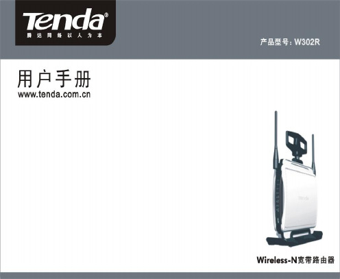
版权申明是深圳市吉祥腾达科技有限公司注册商标。
文中提及到的其它商标或商品名称均是他们所属公司的商标或注册商标。
本产品的所有部分,包括配件和软件,其版权属深圳市吉祥腾达科技有限公司所有,在未经过深圳市吉祥腾达科技有限公司许可的情况下,不得任意拷贝、抄袭、仿制或翻译成其它语言。
本手册中的所有图片和产品规格参数仅供参考,随着软件或硬件的升级会略有差异,如有变更,恕不另行通知,如需了解更多产品信息,请浏览我们的网站:http://目录第1章:产品介绍 (1)第2章:认识Wireless-N宽带路由器 (2)后面板接口说明及图示 (2)前面板图示及说明 (3)硬件安装 (4)第3章:连接到宽带路由器 (5)正确设置您的计算机网络配置 (5)验证网络正常连接 (8)登陆路由器 (10)第4章:基本配置 (11)设置向导 (11)第5章:高级设置 (15)LAN口设置 (15)WAN 设置—虚拟拨号(PPPoE) (16)WAN口设置—静态IP (17)MAC地址克隆 (18)域名服务器设置 (19)第6章:无线设置 (20)无线模式 (19)基本设置 (20)无线安全设置 (24)WPS 设置 (30)WDS 设置 (30)无线高级设置 (31)第7章:DHCP服务设置 (34)DHCP 客户端列表 (35)第8章:虚拟服务器 (35)单端口映射 (35)端口段映射 (38)端口触发 (38)ALG应用 (40)DMZ 主机 (41)UPnP 设置 (43)第9章:带宽控制 (43)第10章:安全设置 (44)客户端过滤 (45)URL 过滤 (46)MAC 地址过滤 (48)防网络攻击 (48)远端WEB管理 (49)本地WEB管理 (50)WAN口Ping (51)第11章:路由设置 (51)路由表 (51)静态路由 (52)第12章:系统工具 (53)时间设置 (53)动态DNS (53)备份/恢复设置 (55)重启路由器 (58)修改登录口令 (58)系统日志 (59)附录:产品特性 (59)第1章:产品介绍感谢您购买W302R Wireless-N宽带路由器(以下简称路由器)。
F2003 GSM IP MODEM无线数据终端说明书
Tel: 0592-6300320
Page 2 of 20 Fax:0592-5权声明
本文档所载的所有材料或内容受版权法的保护,所有版权由厦门四信通信科技有限公司 拥有,但注明引用其他方的内容除外。未经四信公司书面许可,任何人不得将本文档上的任 何内容以任何方式进行复制、经销、翻印、连接、传送等任何商业目的的使用,但对于非商 业目的的、个人使用的下载或打印(条件是不得修改,且须保留该材料中的版权说明或其他 所有权的说明)除外。
第二章 安装.....................................................................................................................................9 2.1 概述....................................................................................................................................9 2.2 开箱...................................................................................................................................9 2.3 安装与电缆连接................................................................................................................9 2.4 电源说明..........................................................................................................................11 2.5 指示灯说明......................................................................................................................11
UF302中文资料

UF300 THRU UF3010ULTRAFAST SWITCHING RECTIFIERVOLTAGE - 50 to 1000 Volts CURRENT - 3.0 AmperesFEATURESl Plastic package has Underwriters Laboratory Flammability Classification 94V-O utilizingFlame Retardant Epoxy Molding Compound l Void-free Plastic in DO-201AD packagel 3.0 ampere operation at T A =55¢J with no thermal runaway l Exceeds environmental standards of MIL-S-19500/228l Ultra fast switching for high efficiencyMECHANICAL DATACase: Molded plastic, DO-201ADTerminals: Axial leads, solderable per MIL-STD-202, Method 208Polarity: Band denotes cathode Mounting Position: AnyWeight: 0.04 ounce, 1.1 gramMAXIMUM RATINGS AND ELECTRICAL CHARACTERISTICS Ratings at 25¢J ambient temperature unless otherwise specified.Resistive or inductive load, 60 HzUF300UF301UF302UF304UF306UF308UF3010UNITS Peak Reverse Voltage, Pepetitive ; V RM 501002004006008001000V Maximum RMS Voltage 3570140280420560700V DC Blocking Voltage; VR501002004006008001000VAverage Forward Current, Io @T A =55¢J 3.8”lead length, 60Hz, resistive or inductive load 3.0APeak Forward Surge Current I FM (surge)8.3msec. single half sine-wave superimposed on rated load (JEDEC method)150A Maximum Forward Voltage V F @3.0A, 25¢J 1.001.10 1.70V Maximum Reverse Current, @ Rated T J =25¢J Reverse Voltage T J =100¢J10.0500£g A £g A Typical Junction capacitance (Note 1) CJ 75.050.0P F Typical Junction Resistance (Note 2) R £K JA 20.0¢J /W Reverse Recovery Time I F =.5A, I R =1A, Irr=.25A50505050757575ns Operating and Storage Temperature Range -55 TO +150¢JNOTES:1. Measured at 1 MHz and applied reverse voltage of 4.0 VDC2. Thermal resistance from junction to ambient and from junction to lead length 0.375”(9.5mm) P.C.B. mountedD O-201ADRATING AND CHARACTERISTIC CURVES UF300 THRU UF3010NOTE:1.Rise Time = 7ns max.Input Impedance = 1 megohm. 22pF 2.Rise Time = 10ns max. Source Impedance = 50 Ohms50 ns/cmFig. 1-REVERSE RECOVERY TIME CHARACTERISTIC AND TEST CIRCUIT DIAGRAMFORWARD VOLTAGE-VFM(Vpk)AMBIENT TEMPERATURE, ¢JFig. 2-FORWARD CHARACTERISTICSFig. 3-FORWARD CURRENT DERATING CURVEPERCENT OF RATED PEAK REVERSE VOLTAGE, %2040 NUMBER OF CYCLES AT 60HzFig. 4-TYPICAL REVERSE LEAKAGECHARACTERISTICSFig. 5-PEAK FORWARD SURGE CURRENT。
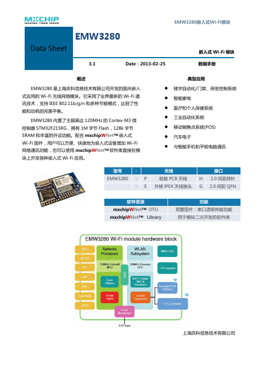
EMW3280中文手册
3.8.2 IEEE802.11b 模式............................................................................................................................................11
移动销售点系统(POS)
ed 汽车电子 reserv 与智能手机和平板电脑通讯
s 型号
-
天线
ht EMW3280 - P
板载 PCB 天线
ig- E 外接 IPEX 天线接头
All r软件资源
接口 H 2.0 间距排针 G 2.0 间距 QFN
功能
mxchipWNetTM -DTU
XCHIPmxchipWNetTM Library
5 6
ts 模块上的产品标签................................................................................................. 19 All righ RECOMMENDED REFLOW PROFILE ................................................................ 20
s 绝对最大参数:电压.......................................................................................................................... 8 ight 电压和电流........................................................................................................................................ 8 All r 数字 IO 口的参数 .............................................................................................................................. 9
罗克韦尔自动化-2080-um002_-zh-e.pdf-Micro830、Micro850 和 M

Micro830、Micro850 和 Micro870可编程控制器Micro810 控制器产品目录号 2080-LC10-12AWA、2080-LC10-12QWB、2080-LC10-12DWD、2080-LC10-12QBBMicro820 控制器产品目录号 2080-LC20-20AWB、2080-LC20-20AWBR、2080-LC20-20QWB、2080-LC20-20QWBR、2080-LC20-20QBB、2080-LC20-20QBBRMicro830 控制器产品目录号 2080-LC30-10QWB、2080-LC30-10QVB、2080-LC30-16AWB、2080-LC30-16QWB、2080-LC30-16QVB、2080-LC30-24QWB、2080-LC30-24QVB、2080-LC30-24QBB、2080-LC30-48AWB、2080-LC30-48QWB、2080-LC30-48QVB、2080-LC30-48QBBMicro850 控制器产品目录号 2080-LC50-24AWB、2080-L50E-24AWB、2080-LC50-24QWB、2080-L50E-24QWB、2080-LC50-24QVB、2080-L50E-24QVB、2080-LC50-24QBB、2080-L50E-24QBB、2080-LC50-48AWB、2080-L50E-48AWB、2080-LC50-48QWB、2080-L50E-48QWB、2080-LC50-48QWBK、2080-L50E-48QWBK、2080-LC50-48QVB、2080-L50E-48QVB、2080-LC50-48QBB、2080-L50E-48QBBMicro870 控制器产品目录号 2080-LC70-24AWB、2080-L70E-24AWB、2080-LC70-24QWB、2080-L70E-24QWB、2080-LC70-24QWBK、2080-L70E-24QWBK、2080-L70E-24QWBN、2080-LC70-24QBB、2080-L70E-24QBB、2080-LC70-24QBBK、2080-L70E-24QBBK、2080-L70E-24QBBN2罗克⻙尔⾃动化出版物2080-UM002M-ZH-E - 2022 年4 月Micro830、Micro850 和 Micro870 可编程控制器⽤⼾⼿册重要⽤⼾须知在安装、配置、操作或维护本产品之前,请阅读本文档以及“其他资源”章节所列的文档,了解关于安装、配置和操作该设备的信息。
MLW3022-00中文资料

Distinctive CharacteristicsActual SizeIndustry’s first miniature snap-in, lighted rocker switch. Actuators in various styles operate with firm, well-defined movements.Interlocking actuator prevents switch failure due to jamming or window locking.Two bezel sizes adapt to varied panel cutouts. Unique stainless steel retaining clips securely hold switches over a range of panel thicknesses, even when exposed to vibration.Space conserving front panel mounting with minimum behind panel dimension of .902” (22.9mm).Durable stainless steel housing prevents corrosion.Isolated lamp circuit for incandescent, LED, and neon lamps. Front panel relamping.Built-in protective cover shields contacts from dust.Epoxy sealed solder lug terminals lock out flux, dust, and other contaminants.Extended lamp terminal for ease of wiring.Matching indicators available and shown at end of section M.General SpecificationsElectrical CapacityPower Level: 5A @ 125V AC, 3A @ 250V AC, & 3A @ 30V DC;Other RatingsContact Resistance: 10 milliohms maximumInsulation Resistance: 200 megohms minimum @ 500V DCDielectric Strength:1,000V AC minimum between contacts for 1 minute minimum;1,500V AC minimum between contacts & case for 1 minute minimum Mechanical Life: 30,000 operations minimum Electrical Life:10,000 operations minimumNominal Operating Force:9.94N for rockers & 4.41N for paddlesAngle of Throw: 24° for On-None-(On); 28° for all other circuitsMaterials & FinishesHousing:Stainless steel Movable Contacts: Silver alloy Stationary Contacts:SilverBase:Phenolic resinCommon Terminal:Copper with silver plating End Terminals: Copper with silver platingLamp Terminals: Phosphor bronze with nickel platingEnvironmental DataOperating Temperature Range:–10°C through +50°C (+14°F through +122°F) Humidity: 90 ~ 95% humidity for 96 hours @ 40°C (104°F)Vibration:10 ~ 55Hz with peak-to-peak amplitude of 1.5mm traversing the frequency range & returning in 1 minute; 3 right angled directions for 2 hoursShock: 50G (490m/s 2) acceleration (tested in 3 right angled directions, with 3 shocks in each direction)InstallationCap Installation Force: 9.80N (2.2 lbf) for rockers;19.61N (4.4 lbf) for paddleSoldering Time & Temperature: Manual Soldering: See Profile A in Supplement section.Standards & CertificationsUL Recognized:All models recognized at 5A @ 125V AC & 3A @ 250V AC; UL File No. WOYR2.E44145Add “/U” to end of part number to order UL mark on switch C-UL Recognized:All models recognized at 5A @ 125V AC & 3A @ 250V AC; C-UL File No. WOYR8.E44145Add “/C-UL” to end of part number to order C-UL mark on switchTYPICAL SWITCH ORDERING EXAMPLECircuitIMPORTANT:Switches are supplied without UL & CSA mark-ings unless specified. Specific models & ratings noted on General Speci- fications page.TERMINALSSwitch Terminals .Lamp TerminalsCenter terminal is .020” (0.5mm) longerThk = (0.8) .031Thk = (0.8) .031LAMP CODES & SPECIFICATIONSElectrical specifications are determined at a basic temperature of 25°C. Lamp circuit is independent of switch operation.For dimension drawings of lamps see Accessories & Hardware section.For neon, if the source voltage is greater than rated voltage, a ballast resistor is required. The ballast resistor calculation and more lamp detail are shown in the Supplement.Incandescent & Neon Lamps for Solid & Design CapsVoltage V 6V AC 12V AC 18V AC 24V AC 28V AC 110V AC Current I80mA 50mA 35mA 25mA 22mA 1.5mA MSCP.159.215.398.215.247NA Endurance Hours 2,000 Average 15,000 Average Ambient Temperature Range–10°C ~ +50°C–10°C ~ +50°CRecommended Resistor for Neon: 33K ohms for 110V AC; 100K ohms for 220V ACNo Lamp Code 00 indicates that no lamp is used.00AT602N NeonT-11⁄2 Pilot Slide Base121806N24AT602Incandescent 28L(+)L(-)LED COLOR CODES & SPECIFICATIONSOPTIONAL BEZELSCAP TYPES & COLORSRA AT405 Rocke rAT438 Design RockerT-13⁄4 Pilot Slide BaseFor Incandescent or Neon LampsRB RC RDRE RF RGPAPB PC PDPE PF PGDB DCDD DFMaterial: Translucent Polycarbonate Standard Finish: GlossyBlack Rocker/Paddle not for use with lamp Opaque Black Rocker BaseLB LC LE LFAT4125 LED RockerSB SCSE SFAT4127 Sculptured RockerMaterial: Translucent Polycarbonate Standard Finish: GlossyColor Codes:BlackWhiteRedOrangeYellowGreenABCDEFBlueG1A AT204 Standard Bezel .787” (20.0mm) Wide1B1C1D1F 1G 1H1E 2A AT9201 Large Bezel .937” (23.8mm) Wide2B2C 2D2F 2G 2H2EDGTranslucent Colored Diffuser Rocker Base.157TYPICAL SWITCH DIMENSIONSWithout BezelSingle & Double PoleActuator in UP position Terminals 4, 5, & 6 are not on single pole modelsMLW3022-12PCStandard Bezel Single & Double PoleActuator in UP position Terminals 4, 5, & 6 are not on single pole modelsMLW3022-12RC-1ALarge BezelSingle & Double PoleActuator in UP position Terminals 4, 5, & 6 are not on single pole modelsMLW3022-12PC-2ASculptured Cap Single & Double PoleActuator in UP position Terminals 4, 5, & 6 are not on single pole modelsMLW3022-CSC-1APANEL CUTOUTS & THICKNESSESWithout Bezel.039” ~ .157” (1.0mm ~ 4.0mm)INSTALLATION & MAINTENANCEWith Standard Bezel AT204.039” ~ .118” (1.0mm ~ 3.0mm)With Large Bezel AT9201.039” ~ .118” (1.0mm ~ 3.0mm)Note: When changing LEDs, match the positive polarity markings on both lamp base and actuator block.LEGENDSGeneral information and basic specifications are presented here for customers who want to do their own legends.Shaded areas are printable areas..030S TO P S T A R TRecommended Print Method:Screen Print or Pad PrintEpoxy based ink is recommendedRockerDesign Rocker Bezel& LED RockerAdditional MethodsAn additional method for legends is engraving the lens. Maximum depth for engraving is.012” (0.3mm) on the cap lens. Enamel paint is recommended to fill the engraved area.Lamps and LEDs can be changed without removing the switch from the panel. The lamps and LEDs.AT107Lamp Extractor。
MOXA UC-2100-W Series硬件用户手册说明书

UC-2100-W Series Hardware User’s ManualVersion 1.0, September 2019/product© 2019 Moxa Inc. All rights reserved.UC-2100-W Series Hardware User’s Manual The software described in this manual is furnished under a license agreement and may be used only in accordance withthe terms of that agreement.Copyright Notice© 2019 Moxa Inc. All rights reserved.TrademarksThe MOXA logo is a registered trademark of Moxa Inc.All other trademarks or registered marks in this manual belong to their respective manufacturers.DisclaimerInformation in this document is subject to change without notice and does not represent a commitment on the part of Moxa.Moxa provides this document as is, without warranty of any kind, either expressed or implied, including, but not limited to, its particular purpose. Moxa reserves the right to make improvements and/or changes to this manual, or to the products and/or the programs described in this manual, at any time.Information provided in this manual is intended to be accurate and reliable. However, Moxa assumes no responsibility for its use, or for any infringements on the rights of third parties that may result from its use.This product might include unintentional technical or typographical errors. Changes are periodically made to the information herein to correct such errors, and these changes are incorporated into new editions of the publication.Technical Support Contact Information/supportMoxa AmericasToll-free: 1-888-669-2872 Tel: +1-714-528-6777 Fax: +1-714-528-6778Moxa China (Shanghai office) Toll-free: 800-820-5036Tel: +86-21-5258-9955 Fax: +86-21-5258-5505Moxa EuropeTel: +49-89-3 70 03 99-0 Fax: +49-89-3 70 03 99-99Moxa Asia-PacificTel: +886-2-8919-1230 Fax: +886-2-8919-1231Moxa IndiaTel: +91-80-4172-9088 Fax: +91-80-4132-1045Table of Contents1.Introduction ...................................................................................................................................... 1-1Overview ........................................................................................................................................... 1-2 Model Descriptions .............................................................................................................................. 1-2 Package Checklist ............................................................................................................................... 1-2 Product Features ................................................................................................................................ 1-2 Product Specifications ......................................................................................................................... 1-2 2.Hardware Introduction...................................................................................................................... 2-1Appearance ........................................................................................................................................ 2-2 LED Indicators .................................................................................................................................... 2-4 Reset Button ...................................................................................................................................... 2-4 Real-time Clock .................................................................................................................................. 2-4 Placement Options .............................................................................................................................. 2-5 Wall or Cabinet Mounting ............................................................................................................. 2-5DIN-rail Mounting (optional) ......................................................................................................... 2-5 3.Hardware Connection Description ..................................................................................................... 3-1Wiring Requirements ........................................................................................................................... 3-2 Connecting the Power .................................................................................................................. 3-2Grounding the Unit ...................................................................................................................... 3-2 Connecting to the Console Port ............................................................................................................. 3-3 Connecting to the Network ................................................................................................................... 3-3 Connecting to a Serial Device ............................................................................................................... 3-4 Inserting the SIM Card ........................................................................................................................ 3-4 Inserting a MicroSD Card (UC-2114/2116 only) ...................................................................................... 3-4 Adjusting the DIP Switch ..................................................................................................................... 3-5 A.Regulatory Approval Statements ....................................................................................................... A-11Introduction The UC-2100-W Series platform is designed for embedded data acquisition applications. The platform comes with one or two RS- 232/422/485 serial ports and dual 10/100 Mbps Ethernet LAN ports, as well as a Mini PCIe socket to support cellular modules. These versatile communication capabilities let users efficiently adapt the UC-2100-W Series platform to a variety of complex communications solutions.The following topics are covered in this chapter:❒Overview❒Model Descriptions❒Package Checklist❒Product Features❒Product SpecificationsUC-2100-W Series HW UM IntroductionOverviewThe UC-2100-W Series computing platform is designed for embedded data acquisition and processingapplications. The platform comes with up to two software-selectable RS-232/422/485 full-signal serial ports and single or dual Ethernet LAN ports. In addition, the Arm-based computing platform is available in various models that can fulfill diverse interface requirements, such as dual serial, LAN ports, and wireless connections.These versatile communication capabilities let users efficiently adapt the palm-sized UC-2100-W computing platform to a variety of complex communications solutions.Model DescriptionsThe UC-2100-W Series includes the following models:UC-2114-T-LX: Palm-sized industrial computing platform with 2 serial ports, 2 Ethernet ports, 2 CAN ports, -40 to 75°C operating temperature with CAT.M1/NB-IoT built-in.UC-2116-T-LX: Palm-sized industrial computing platform with 2 serial ports, 2 Ethernet ports, 2 CAN ports, -40 to 75°C operating temperature with CAT.M1/NB-IoT and GNSS built-in.Package ChecklistBefore installing a UC-2100-W Series platform, verify that the package contains the following items:•UC-2100-W Series platform•Console cable•Power jack•Quick Installation Guide (printed)•Warranty cardNOTE: Notify your sales representative if any of the above items are missing or damaged.Product Features•Armv7 Cortex-A8 1000 MHz processor•Integrated LTE Cat. M1/NB1 module with global band support•Dual-SIM slots•Moxa Industrial Linux with 10-year long-term support•Dual auto-sensing Ethernet ports (10/100 Mbps and 10/100/1000 Mbps)•Dual CAN ports with industrial CAN 2.0 A/B protocol supported•microSD socket for storage expansion•Programmable LEDs and a programmable button for easy installation and maintenance•-40 to 75°C operating temperature rangeFor a complete set of specifications, refer to the product datasheet available on the Moxa Website. Product SpecificationsNOTE The latest specifications for Moxa's products can be found at https://.2Hardware Introduction The UC-2100-W Series computing platform are compact and rugged, making them suitable for industrial applications. The LED indicators allow you to monitor performance and identify trouble spots quickly, and the multiple ports can be used to connect a variety of devices. The UC-2100-W Series comes with a reliable and stable hardware platform that lets you devote the bulk of your time to application development. In this chapter, we provide basic information about its various components.The following topics are covered in this chapter:❒Appearance❒LED Indicators❒Reset Button❒Real-time Clock❒Placement OptionsW all or Cabinet MountingD IN-rail Mounting (optional)Appearance Front ViewUC-2114UC-2116Dimensions [units: mm (in)] UC-2114UC-2116LED IndicatorsRefer to the following table for information about each LED. LED Name Status FunctionPower GreenPower is on, and the device is functioning normally Off Power is offEthernet (10/100 Mbps)GreenSteady On: 10 Mbps Ethernet link Blinking: Data transmission is in progress Yellow Steady On: 100 Mbps Ethernet link Blinking: Data transmission is in progressOffSpeed lower than 10 Mbps or the cable is not connected Ethernet(10/100/1000 Mbps)Green Steady On: 100 Mbps Ethernet link Blinking: Data transmission is in progress Yellow Steady On: 1000 Mbps Ethernet link Blinking: Data transmission is in progressOffSpeed lower than 10 Mbps or the cable is not connected Serial (Tx) Green Serial port is transmitting data Off Serial port is not transmitting data Serial (Rx) Yellow Serial port is receiving data Off Serial port is not receiving dataUserGreen/Yellow User ProgrammableLEDs that indicate the Wireless signal strengthYellow The number of glowing LEDs indicates the signal strength 3 LEDs: Excellent 2 LEDs : Good 1 LED : PoorOffWireless module is not detected CAN1/CAN2 (Tx) Green CAN port is transmitting data Off CAN port is not transmitting data CAN1/CAN2 (Rx)Green CAN port is receiving data OffCAN port is not receiving dataReset ButtonThe UC-2100-W is provided with a reset button, which is located on the side panel. To reboot the device, press the reset button less than 1 second. Press and hold the reset button between 7 to 9 seconds to reset the device to the factory default settings. When the reset button is held down, the User LED will blink twice every second. The User LED will become steady when you hold the button continuously for 7 to 9 seconds. Release the button within this period to load the factory default settings.Real-time ClockThe UC-2100-W’s real time clock is powered by a non-chargeable battery. We strongly recommend that you do not replace the lithium battery without help from a qualified Moxa support engineer. If you need to change the battery,contacttheMoxaRMAserviceteam(************).Placement OptionsThere are two sliders on the back of the unit for DIN-rail and wall mounting.Wall or Cabinet MountingMounting UC-2100-W on to a wall requires 2 screws. The heads of the screws should be less than 7.0 mm in diameter, the shafts should be less than 3 mm in diameter, and the length of the screws should be more than 8 mm, as shown in the figure at the bottom.NOTEBefore tightening the screws into the wall, make sure the screw head and shank size are suitable by inserting the screw into one of the keyhole-shaped apertures of the wall mounting plates.DIN-rail Mounting (optional)The UC-2100-W comes with an optional DIN-rail mounting kit for users to install the device onto a DIN rail. Install the DIN-rail mounting kit on the device’s two mounting ears, then install the computer onto a DIN-rail rack.3 Hardware Connection DescriptionIn this chapter, we describe how to connect the UC-2100-W to a network and various devices for first time testing purposes.The following topics are covered in this chapter:❒Wiring RequirementsC onnecting the PowerG rounding the Unit❒Connecting to the Console Port❒Connecting to the Network❒Connecting to a Serial Device❒Inserting the SIM Card❒Inserting a MicroSD Card (UC-2114/2116 only)❒Adjusting the DIP SwitchWiring RequirementsIn this section, we describe how to connect various devices to the platform. You should heed the following common safety precautions before proceeding with the installation of any electronic device:• Use separate paths to route wiring for power and devices. If power wiring and device wiring paths mustcross, make sure the wires are perpendicular at the intersection point.NOTE: Do not run signal or communication wiring and power wiring in the same wire conduit. To avoid interference, wires with different signal characteristics should be routed separately.• You can use the type of signal transmitted through a wire to determine which wires should be kept separate.The rule of thumb is that wiring that shares similar electrical characteristics can be bundled together. • Keep input wiring and output wiring separate.• When necessary, it is strongly advised that you label wiring to all devices in the system.Connecting the PowerTerminal BlockConnect the 9 to 48 VDC power line to the terminal block connector on the UC-2100-W Series platform. If the power is supplied properly, the “Power” LED will glow a solid green. The power input location and pin definition are shown in the adjacent diagram.Grounding the UnitGrounding and wire routing help limit the effects of noise due to electromagnetic interference (EMI). Run the ground connection from the ground screw to the grounding surface prior to connecting devices.SG: The Shielded Ground (sometimes called Protected Ground) contact is the right-most contact of the 3-pin power terminal block connector when viewed from the angle shown here. Connect the SG wire to an appropriate grounded metal surface.Connecting to the Console PortThe UC-2100-W’s console port is a 4-pin pin-header RS-232 port located on the top panel of the case. It is designed for serial console terminals, which are useful for identifying the boot up message, or for debugging when the system cannot boot up. Serial Console Port & PinoutsSerial Console CablePin Signal 1 TxD 2 RxD 3NC 4GNDConnecting to the NetworkThe Ethernet ports are located on the top or bottom side of the UC-2100-W platform. The pin assignments for the Ethernet port are shown in the following figures. If you are using your own cable, make sure that the pin assignments on the Ethernet cable connector match the pin assignments on the Ethernet port.Pin 10/100 Mbps10/100/1000 Mbps1 Tx+ TRD(0)+ 2Tx- TRD(0)- 3 Rx+ TRD(1)+ 4 – TRD(2)+ 5 – TRD(2)- 6 Rx- TRD(1)- 7 – TRD(3)+ 8–TRD(3)-Connecting to a Serial DeviceThe serial ports are located on the bottom panel of the UC-2100-W Series platform. Use a serial cable to connect your serial device to the computer’s serial port. These serial ports have male DB9 connectors and can be configured for RS-232, RS-422, or RS-485 communication. The pin location and assignments are shown in the following table.DB9 ConnectorRS-232/422/485 PinoutsPin RS-232 RS-422 RS-485 (4-wire)RS-485 (2-wire)1 DCD TxDA(-) TxDA(-)– 2 RxD TxDB(+) TxDB(+)– 3 TxD RxDB(+) RxDB(+) DataB(+) 4 DTR RxDA(-) RxDA(-) DataA(-) 5GND GND GND GND 6 DSR – – – 7 RTS – – – 8CTS–––Inserting the SIM CardYou will need to install a SIM card on your UC-2100-W Series platform. Follow these steps to install the SIM card.1. Remove the screw on the cover located on the right panel of theUC-2100-W platform.2. Insert the SIM card into the socket. Make sure you place the chip-side onthe bottom.3. To remove the SIM card, push in the SIM card and then release it to allowthe card to pop out.Inserting a MicroSD Card (UC-2114/2116 only)Both the UC-2114 and UC-2116 computers come with a storage socket that allows users to install one MicroSD card. Follow these steps to install the MicroSD card:1. The MicroSD socket is located below the right panel of the device.Unfasten the screw and remove the right panel cover.2. Insert the MicroSD card into the socket.Ensure that the card is inserted in the right direction.3. Replace the cover and fasten the screw on the cover to secure the cover. To remove the MicroSD card, push the card in and release it to allow the card to pop out.Adjusting the DIP SwitchThe UC-2114 and UC-2116 models come with one DIP switch for users to adjust the serial port parameters. To set up the DIP switch, do the following:1. Remove the screws on the DIP switch cover located on the rear panel of thedevice.2. Remove the thin film on the DIP switch and adjust the settings as required.Refer to the table below for the DIP switch settings. The default value is OFF.SW 1 2 3 4 Low High Term. – ON 1 K Ω 1 K Ω 120 Ω – OFF150 K Ω150 K Ω––ARegulatory Approval StatementsThis device complies with part 15 of the FCC Rules. Operation is subject to the following two conditions: (1) This device may not cause harmful interference, and (2) this device must accept any interference received, including interference that may cause undesired operation.Class A: FCC Warning! This equipment has been tested and found to comply with the limits for a Class A digital device, pursuant to part 15 of the FCC Rules. These limits are designed to provide reasonable protection against harmful interference when the equipment is operated in a commercial environment. This equipment generates, uses, and can radiate radio frequency energy and, if not installed and used in accordance with the instruction manual, may cause harmful interference to radio communications. Operation of this equipment in a residential area is likely to cause harmful interference in which case the users will be required to correct the interference at their own expense.European Community。
MN020X用户手册正文-中英文(2012-5-23)2-2
前言ForewordMN020X系列全自动耐压测试仪,是一种高性能电气强度专用测试仪器。
可软件设置输出电压、漏电流报警值、测试时间等,具有多种自动测试功能。
The MN020X Series Full Automatic V oltage-withstand Tester is a high performance electrical intensity tester which is used to set output voltage, leakage current alarm value, test time via software with various automatic test functions.该系列测试仪高压输出准确度高(优于2%),漏电流测试精度高(优于2%),可配置有RS-232计算机接口、遥控接口,既适用于生产线快速化流水检测,又适合于实验室多功能高精度要求。
The Tester has high voltage output accuracy(better than 2%),high leakage current test precision(better than 2%),equipped with RS-232 computer port, remote control port, is suitable for fast test in production line as well as high-precision test in labs.仪器的测量原理符合《GB4706.1》、《GB3883.1》、《GB4943》安全性能检测要求,可对采用基本绝缘、附加绝缘和加强绝缘的器具进行电气强度测试。
适用于家用电器、仪器仪表、办公设备、电动工具、绝缘材料的电气强度试验。
The test principle is in accordance with safety test requirement of 《GB4706.1》、《GB3883.1》、《GB4943》,and may test the electrical intensity of devices with basic insulation, appendix insulation or enhanced insulation, which is suitable for electrical intensity test of home appliance, instrument, office equipment, electrical tool and insulation material.第一章安全规则Chapter 1 Safety Regulation本规则确认高电压测试前应该注意的规定和事项!This is to regulate the precaution before the high voltage test!1.1 安全规定及标志Safety regulation and symbol●本测试仪的安全要求符合<GB4793.1>、<IEC1010-1>标准。
莫雅 UC-2100-W 系列 ARM 基于无线小型工业计算机说明书

UC-2100-W SeriesArm-based wireless-enabled palm-sized industrial computerFeatures and Benefits•Armv7Cortex-A81000MHz processor•Integrated LTE Cat.M1/NB1module with global band support•Dual-SIM slots•Moxa Industrial Linux with10-year long-term support•Dual auto-sensing Ethernet ports(10/100Mbps and10/100/1000Mbps)•Dual CAN ports with industrial CAN2.0A/B protocol supported•microSD socket for storage expansion•Programmable LEDs and a programmable button for easy installation andmaintenance•-40to75°C operating temperature rangeCertificationsIntroductionThe UC-2100-W Series computing platform is designed for embedded data acquisition and processing applications.The computer comes with up to two software selectable RS-232/422/485full-signal serial ports and single or dual LAN ports.This palm-sized series of Arm-based computing platforms includes a variety of models for a wide range of interface requirements,such as serial and LAN ports,and wireless connections.The versatile communication capabilities allow users to efficiently adapt the UC-2100-W Series for a variety of complex communications solutions running on a compact palm-sized computer.The UC-2100-W Series has a built-in Cortex-A8Arm-based processor that has been optimized for a variety of industrial solutions.With flexible interface options,this tiny embedded computer is a reliable and secure gateway for data acquisition and processing at field sites and is a useful communication platform for many other large-scale deployments.Models designed for wide-temperature applications are available for extreme environments such as those found in the Oil and Gas industry.Furthermore,all models use Moxa’s industrial-grade Linux platform,which provides optimized software features and superior long-term support.AppearanceUC-2114UC-2116SpecificationsComputerCPU Armv7Cortex-A81GHz DRAM512GB DDR3Storage Pre-installed8GB eMMCPre-installed OS Moxa Industrial Linux(Debian9,Kernel4.4)Computer InterfaceStorage Slot Micro SD Slot x1Ethernet Ports Auto-sensing10/100Mbps ports(RJ45connector)x1Auto-sensing10/100/1000Mbps ports(RJ45connector)x1Serial Ports RS-232/422/485ports x2,software-selectable(terminal block)CAN Ports CAN2.0A/B x2(5-pin terminal block)Cellular Antenna Connector SMA x1GPS Antenna Connector SMA x1Number of SIMs2SIM Format NanoConsole Port RS-232(TxD,RxD,GND),4-pin header output(115200,n,8,1)Buttons Reset buttonEthernet InterfaceMagnetic Isolation Protection 1.5kV(built-in)Serial InterfaceBaudrate50bps to921.6kbpsData Bits5,6,7,8Stop Bits1,1.5,2Parity None,Even,Odd,Space,MarkPull High/Low Resistor for RS-4851kilo-ohm,150kilo-ohmsESD Protection4kV,for all signalsFlow Control RTS/CTS,XON/XOFF,ADDC®(automatic data direction control)for RS-485,RTSToggle(RS-232only)Serial SignalsRS-232TxD,RxD,RTS,CTS,DTR,DSR,DCD,GNDRS-422Tx+,Tx-,Rx+,Rx-,GNDRS-485-2w Data+,Data-,GNDRS-485-4w Tx+,Tx-,Rx+,Rx-,GNDCAN InterfaceIndustrial Protocols CAN2.0A,CAN2.0BBaudrate10to1000kbpsSignals GND,CAN_L,CAN_SHLD,CAN_H,CAN_V+Isolation2kV(built-in)Cellular InterfaceBand Options LTE Bands:Band1(2100MHz)/Band2(1900MHz)/Band3(1800MHz)/Band4(1700MHz)/Band5(850MHz)/Band8(900MHz)/Band12(700MHz)/Band13(700MHz)/Band18(850MHz)/Band19(850MHz)/Band20(800MHz)/Band25(1900MHz)/Band26(850MHz)/Band28(700MHz)Carrier Approval:Verizon,AT&TLED IndicatorsSystem Power x1Programmable x1LAN2per port(10/100Mbps)Serial2per port(Tx,Rx)Wireless Signal Strength3CAN2per port(Tx,Rx)Power ParametersInput Voltage9to48VDCPower Consumption 5.8WInput Current0.6A@9VDC,0.12A@48VDCReliabilityAlert Tools External RTC(real-time clock)Automatic Reboot Trigger External WDT(watchdog timer)Physical CharacteristicsHousing MetalDimensions(with ears)111x99x34.5mm(4.37x3.90x1.36in)Weight396g(0.87lb)Installation Wall-mounting,DIN-rail mounting(with optional kit)Environmental LimitsOperating Temperature-40to75°C(-40to167°F)Storage Temperature(package included)-40to85°C(-40to185°F)Ambient Relative Humidity5to95%(non-condensing)Standards and CertificationsSafety EN62368-1,UL62368-1EMC EN55032/24EMI CISPR32,FCC Part15B Class AEMS IEC61000-4-2ESD:Contact:4kV;Air:8kVIEC61000-4-3RS:80MHz to1GHz:3V/mIEC61000-4-4EFT:Power:1kV;Signal:0.5kVIEC61000-4-5Surge:Power:0.5kV;Signal:1kVIEC61000-4-6CS:3VIEC61000-4-8PFMFShock IEC60068-2-27Vibration2Grms@IEC60068-2-64,random wave,5-500Hz,1hr per axis(without any USBdevices attached)Hazardous Locations Class I Division2,ATEX,IECEx1Green Product RoHS,CRoHS,WEEEMTBFTime UC-2114-T-LX:533,149hrsUC-2116-T-LX:496,650hrsStandards Telcordia(Bellcore)StandardWarrantyWarranty Period5yearsDetails See /warrantyPackage ContentsDevice1x UC-2100-W Series computerInstallation Kit1x power jackCable1x console cableDocumentation1x quick installation guide1x warranty card1.Class1Division2,ATEX,and IECEx certifications are underway.Please contact a Moxa sales representative for details.DimensionsUC-2114UC-2116Ordering InformationModel Name CPU RAM Storage Serial Ethernet CAN Cellular GPS Operating Temp.UC-2114-T-LX 1000MHz512MB8GB22(1Giga LAN)2BN-IoT/Cat.M1–-40to75°CUC-2116-T-LX 1000MHz512MB8GB22(1Giga LAN)2BN-IoT/Cat.M1Yes-40to75°CAccessories(sold separately)Power AdaptersPWR-24270-DT-S1Power adapter,input voltage90to264VAC,output voltage24V with2.5A DC load Power CordsPWC-C7US-2B-183Power cord with United States(US)plug,10A/125V,1.83mPWC-C7EU-2B-183Power cord with Continental Europe(EU)plug,2.5A/250V,1.83mPWC-C7UK-2B-183Power cord with United Kingdom(UK)plug,2.5A/250V,1.83mPWC-C7AU-2B-183Power cord with Australian(AU)plug,2.5A/250V,1.83mPWC-C7CN-2B-183Power cord with two-prong China(CN)plug,1.83mCablesCBL-F9DPF1x4-BK-100Console cable with4-pin connector,1mAntennasANT-LTEUS-ASM-01GSM/GPRS/EDGE/UMTS/HSPA/LTE,omni-directional rubber duck antenna,1dBiANT-GPS-OSM-05-3M BK Active GPS antenna,26dBi,1572MHz,L1band antenna for GPSANT-LTE-ASM-04BK LTE Stick antenna that covers704-960/1710-2620MHz providing omnidirectional radiation with a gainof4.5dBi.ANT-LTE-OSM-06-3m BK MIMO Multi-band antenna that covers700-2700/2400-2500/5150-5850MHz frequencies.Screw-fastenedmounting and full IP67waterproofing are available.ANT-LTE-OSM-03-3m BK Multi-band antenna that covers700-2700MHz.Specially designed for2G,3G,and4G applications.Magnetic mounting is availableANT-LTE-ASM-05BK LTE stick antenna that covers704-960/1710-2620MHz with a gain of5dBi.DIN-Rail Mounting KitsDK35A DIN-rail mounting brackets x2,screws x4©Moxa Inc.All rights reserved.Updated Nov05,2019.This document and any portion thereof may not be reproduced or used in any manner whatsoever without the express written permission of Moxa Inc.Product specifications subject to change without notice.Visit our website for the most up-to-date product information.。
NETGEAR_wg302说明书

NETGEAR WG302 快速安装手册第1步登录WG302无线接入点管理界面设置WG302,首先需要登录WG302的管理界面。
下面介绍两种登录管理页面的方法: 通过WG302默认的IP地址访问1.将WG302连接到计算机,如下图所示:2.将计算机的IP地址设置为192.168.0.x;3.登录AP管理界面(1)启动计算机的Internet Explorer或者Netscape Navigator等其他浏览器,在浏览器的地址栏键入http://192.168.0.227后,点击回车:(2)WG302会要求提供用户名和密码。
登录用户名:admin,密码:password,注意用户名和密码都是小写。
∙通过WG302默认AP名来访问,默认的AP名为netgear加上此设备MAC地址的后六位,如MAC地址为00:0F:B5:93:4F:FB,则AP名为netgear934ffb。
1. 将AP和计算机连接到同一个网络中2. 将计算机网卡的IP地址设为“自动获取IP地址”3. 登录AP管理界面(1)启动计算机的Internet Explorer或者Netscape Navigator等其他浏览器,在浏览器的地址栏键入http://netgear934ffb后,点击回车:(2)WG302会要求提供用户名和密码。
登录用户名:admin,密码:password,注意用户名和密码都是小写。
第2步WG302的IP地址及无线参数设置∙IP地址设置登录WG302管理界面,点击IP Settings选项,进入IP Setting页面。
WG302默认开启DHCP客户端功能。
1. 假如您的网络中有DHCP服务器,希望WG302获取一个动态IP地址,则无需做任何设置;2. 假如您希望给WG302指定一个IP地址,则将DHCP Client选项设为Disable,设置固定的IP地址,然后点击Apply即可。
∙无线参数设置点击Setup→Wireless Settings,进入Wireless Settings页面。
英菲(InfiNet)无线产品InfiMAN资料

与传统的点对多点系统比较,通过先进的多入多出技术和自适应的多点接 入协议,覆盖范围和链路可靠性都得到了很大的提高。
InfiMAN 2x2 系列可以给那些需要远距离覆盖提供快速以太网的数据、语 音以及视频业务的各类运营商提供独特的解决方案,(例如:WISP,各种 规模的组织,政府机构等),具有广泛的网络特性同时保证严格的服务质 量(QoS)控制。
·最高12瓦
·最高7瓦
·110-240V AC@ 50/60Hz ·110-240V AC@ 50/60Hz
·48伏直流电
·12-48伏直流电
·室外单元(ODU): 370x370x85mm 3.7kg
·室内单元(IDU-BS-G): 124x72x38mm 0.3kg
·室外单元(ODU): 240x240x51mm 2.3kg
40 MHz ·集成天线:
·双极化21/23/28dBi
·发射功率:18dBm ·接收机灵敏度: -67
~-101dBm ·频段:4.9~6.0GHz ·信道带宽:5/10/20/
40 MHz ·2个N型天线接口
·发射功率:18dBm ·接收机灵敏度: -67
~-101dBm ·频段:4.9~6.0GHz ·信道带宽:5/10/20/ 40 MHz ·集成19dBi双极化天线
QoS服务质量
拥有许多QoS排列,QoS在网络中 的透明的工作模式基于802.11p以及 ToS/DiffServ标准,针对任意负载及 最低抖动/时延优先级的流量保证其 完美的性能服务质量QoS特性 • 16个优先等级队列 • 支持IEEE802.1p • 支持IP ToS/DiffServ • 完全支持语音 • 流量限速(绝对,相对以及混合) • 流量重定向
高能立方AC-DC电源模块产品选型手册
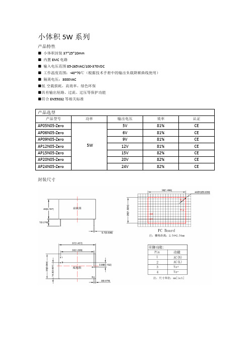
小体积5W系列产品特性■小体积封装37*25*20mm■内置EMC电路■输入电压范围85-265VAC/100-370VDC■工作温度范围:-40~70℃(根据技术手册中的输出负载降额曲线使用)■隔离电压:3000VAC■低空载损耗,高效率,绿色环保■具有输出短路、过流、过压等保护功能■符合EN55032等相关标准封装尺寸小体积7W系列产品特性■小体积封装37*28*20mm■内置EMC电路■输入电压范围85-265VAC/100-370VDC■工作温度范围:-40~70℃(根据技术手册中的输出负载降额曲线使用)■隔离电压:3000VAC■低空载损耗,高效率,绿色环保■具有输出短路、过流、过压等保护功能■符合EN55032等相关标准封装尺寸产品特性■小体积封装27*37*17mm■输入电压范围85-265VAC/100-370VDC■工作温度范围:-40~70℃(根据技术手册中的输出负载降额曲线使用)■隔离电压:3000VAC■低空载损耗,高效率,绿色环保■具有输出短路、过流、过压等保护功能封装尺寸产品特性■小体积封装25.5*39.5*22mm■输入电压范围85-265VAC/100-370VDC■工作温度范围:-40~70℃(根据技术手册中的输出负载降额曲线使用)■隔离电压:3000VAC■低空载损耗,高效率,绿色环保■具有输出短路、过流、过压等保护功能封装尺寸产品特性■小体积封装36*48*23mm■输入电压范围85-265VAC/100-370VDC■工作温度范围:-40~70℃(根据技术手册中的输出负载降额曲线使用)■隔离电压:3000VAC■低空载损耗,高效率,绿色环保■具有输出短路、过流、过压等保护功能封装尺寸产品特性■小体积封装36*48*23mm■输入电压范围85-265VAC/100-370VDC■工作温度范围:-40~70℃(根据技术手册中的输出负载降额曲线使用)■隔离电压:3000VAC■低空载损耗,高效率,绿色环保■具有输出短路、过流、过压等保护功能封装尺寸三线四相24W单路系列产品特性■小体积封装25.5*39.5*22mm■输入电压范围85-450VAC/100-630VDC■工作温度范围:-40~70℃(根据技术手册中的输出负载降额曲线使用)■隔离电压:3000VAC■低空载损耗,高效率,绿色环保■具有输出短路、过流、过压等保护功能封装尺寸24W正负双路输出系列产品特性■小体积封装25.5*39.5*22mm■输入电压范围85-265VAC/100-370VDC■工作温度范围:-40~70℃(根据技术手册中的输出负载降额曲线使用)■隔离电压:3000VAC■低空载损耗,高效率,绿色环保■具有输出短路、过流、过压等保护功能封装尺寸。
SF302中文资料
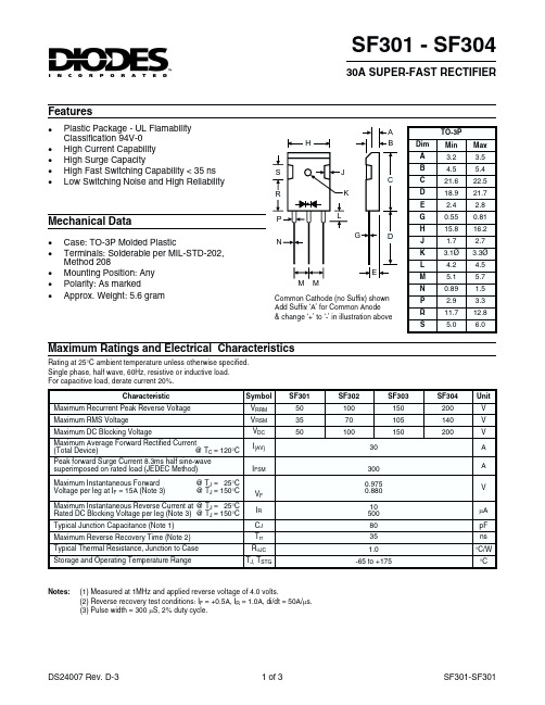
SF301 - SF30430A SUPER-FAST RECTIFIERFeatures·Case: TO-3P Molded Plastic·Terminals: Solderable per MIL-STD-202,Method 208·Mounting Position: Any ·Polarity: As marked·Approx. Weight: 5.6 gramMechanical DataMaximum Ratings and Electrical CharacteristicsCharacteristicSymbol SF301SF302SF303SF304Unit Maximum Recurrent Peak Reverse Voltage V RRM 50100150200V Maximum RMS Voltage V RSM 3570105140V Maximum DC Blocking VoltageV DC 50100150200V Maximum Average Forward Rectified Current (Total Device)@ T C = 120°C I (AV)30A Peak forward Surge Current 8.3ms half sine-wave superimposed on rated load (JEDEC Method)I FSM300A Maximum Instantaneous Forward @T J =25°C Voltage per leg at I F = 15A (Note 3)@T J = 150°CV F 0.9750.880V Maximum Instantaneous Reverse Current at @T J =25°C Rated DC Blocking Voltage per leg (Note 3)@T J = 150°C I R 10500m A Typical Junction Capacitance (Note 1)C J 80pF Maximum Reverse Recovery Time (Note 2)T rr 35ns Typical Thermal Resistance, Junction to Case R q JC 1.0°C/W Storage and Operating Temperature RangeT J,T STG-65 to +175°CNotes:(1)Measured at 1MHz and applied reverse voltage of 4.0 volts.(2)Reverse recovery test conditions: I F = +0.5A, I R = 1.0A,di/dt = 50A/m s.(3)Pulse width = 300m S, 2% duty cycle.Rating at 25°C ambient temperature unless otherwise specified.Single phase, half wave, 60Hz, resistive or inductive load.For capacitive load, derate current 20%.TO-3PDim Min Max A 3.2 3.5B4.55.4C 21.622.5D 18.921.7E 2.4 2.8G 0.550.81H15.816.2J 1.7 2.7K 3.1Ø 3.3ØL4.2 4.5M5.1 5.7N 0.89 1.5P 2.9 3.3R 11.712.8S5.06.0A BEGJ LMNP K S MHRDCCommon Cathode (no Suffix) shown Add Suffix ‘A’ for Common Anode & change ‘+’ to ‘-’ in illustration above·Plastic Package - UL Flamability Classification 94V-0·High Current Capability ·High Surge Capacity·High Fast Switching Capability < 35 ns ·Low Switching Noise and High ReliabilityI ,A V E R A G E F W D R E C T I F I E D C U R R E N T (A )A V 25507510012515005101520TEMPERATURE (°C)Fig.1,T ,Forward Current Derating CurveC 11010050100150200250300350400NUMBER OF CYCLES AT 60Hz Fig.4Peak Forward Surge CurrentI ,P E A K F W D S U R G E C U R R E N T (A )F S M 110100V ,REVERSE VOLTAGE (VOLTS)Fig.3Typical Junction CapacitanceR 101001000C ,J U N C T I O N C A P A C I T A N C E (p F )J 00.40.81.2 1.62.00.11.010100V ,INSTANTANEOUS FORWARD VOLTAGE (VOLTS)Fig.2Typical Forward CharacteristicsF I ,I N S T A N T A N E O U S F W D R E C T I F I E D C U R R E N T (A )P e r L e gF40801601202000.010.11.010V ,REVERSE VOLTAGE (VOLTS)Fig.5,Typical Reverse CharacteristicsR I ,I N S T A N T A N E O U S R E V E R S E C U R R E N T (µA )R -1.0A-0.25A+0.5A10W Non Inductive50W Non Inductive Notes:1.Rise Time =7ns max,nce =1MW 22pF2.Rise Time =10ns max Source Impedence =50W。
MP902技术规格书

MP902产品技术规范版本V ersion:V1.00发布日期Date:18/4/2008文件编号Document Number:xxxx深圳梦网科技发展有限公司本文档适用的产品是MP902彩信监控器。
本文档以MP902产品为例,主要介绍MP902产品的外观、硬件结构、功能、技术规格和模块有关指标的测试标准,用于帮助市场技术支持工程师提供技术支持及测试人员测试提供参考。
阅读对象本文档主要适用于以下工程师:产品工程师市场技术支持工程师测试工程师修改记录修订记录累积了每次文档更新的说明。
最新版本的文档包含以前所有文档版本的更新内容。
文档版本V1.0 (2008-04-18)第一次正式发布。
目录1 产品简介 (1)2 缩略语 (1)3外观和结构 (2)4功能 (3)4.1主要功能定义 (3)5主要技术规格 (4)5.1通讯协议及技术指标 (4)5.2射频接收 (4)5.3遥控接收 (4)5.4天线 (4)5.5主要性能指标 (5)5.6待机时间 (5)5.7工作条件 (5)6可靠性测试标准 (6)6.1跌落实验 (6)6.2振动实验 (6)6.3低温运行实验 (6)6.4低温存储实验 (7)6.5高温运行实验 (7)6.6高温存储实验 (7)6.7高温高湿实验 (8)6.8高低温冲击实验 (8)7 EMC/EMI测试标准 (8)7.1静电放电试验(ESD) (8)7.2射频电磁场辐射抗扰性试验 (9)7.3电快速瞬变脉冲群抗扰性试验 (9)7.4雷击浪涌抗扰性试验 (10)7.5射频电磁场传导抗扰性试验 (10)7.6电压瞬时跌落和短时中断的抗扰性试验 (11)7.7辐射发射试验 (11)8引用标准 (11)9产品齐套 (12)1产品简介深圳梦网科技发展有限公司是一家生产GSM/CDMA无线终端产品的国内知名企业,是国内最早开发和批量生产GSM、CDMA无线终端产品的厂商,拥有多年的研发与生产经验。
V90-B1.1彩信监控器是利用图像移动侦测和被动红外人体感应技术,将监控现场的异常用摄像头拍摄下来,经图像压缩,再经GSM模块通过移动通信网的彩信服务、GPRS功能,将现场拍摄到的画面传输到指定用户手机、邮箱或互联网管理平台的无线监控设备。
Mellanox WinOF-2 产品知识库说明书
Mellanox Technologies Mellanox WinOF-2 Known IssuesLast Updated: 01 March 2018Mellanox Technologies350 Oakmead Parkway Suite 100Sunnyvale , CA 94085U.S.A.Tel: (408) 970-3400Fax: (408) 970-3403© Copyright 2018. Mellanox Technologies Ltd. All Rights Reserved.Mellanox®, Mellanox logo, Accelio®, BridgeX®, CloudX logo, CompustorX®, Connect -IB®, ConnectX®, CoolBox®, CORE-Direct®, EZchip®, EZchip logo, EZappliance®, EZdesign®, EZdriver®, EZsystem®, GPUDirect®, InfiniHost®, InfiniBridge®, InfiniScale®, Kotura®, Kotura logo, Mellanox CloudRack®, Mellanox CloudXMellanox®, Mellanox Federal Systems®, Mellanox HostDirect®, Mellanox Multi-Host®, Mellanox Open Ethernet®, Mellanox OpenCloud®, Mellanox OpenCloud Logo®, Mellanox PeerDirect®, Mellanox ScalableHPC®, Mellanox StorageX®, Mellanox TuneX®, Mellanox Connect Accelerate Outperform logo , Mellanox Virtual Modular Switch®, MetroDX®, MetroX®, MLNX-OS®, NP-1c®, NP-2®, NP-3®, NPS®, Open Ethernet logo , PhyX®, PlatformX®, PSIPHY®, SiPhy®, StoreX®, SwitchX®, Tilera®, Tilera logo, TestX®, TuneX®, The Generation of Open Ethernet logo , UFM®, Unbreakable Link®, Virtual Protocol Interconnect®, Voltaire® and Voltaire logo are registered trademarks of Mellanox Technologies , Ltd.All other trademarks are property of their respective owners .For the most updated list of Mellanox trademarks, visit /page/trademarksNOTE:THIS HARDWARE, SOFTWARE OR TEST SUITE PRODUCT (“PRODUCT(S)”) AND ITS RELATED DOCUMENTATION ARE PROVIDED BY MELLANOX TECHNOLOGIES “AS -IS” WITH ALL FAULTS OF ANY KIND AND SOLELY FOR THE PURPOSE OF AIDING THE CUSTOMER IN TESTING APPLICATIONS THAT USE THE PRODUCTS IN DESIGNATED SOLUTIONS. THE CUSTOMER'S MANUFACTURING TEST ENVIRONMENT HAS NOT MET THE STANDARDS SET BY MELLANOX TECHNOLOGIES TO FULLY QUALIFY THE PRODUCT(S) AND/OR THE SYSTEM USING IT . THEREFORE, MELLANOX TECHNOLOGIES CANNOT AND DOES NOT GUARANTEE OR WARRANT THAT THE PRODUCTS WILL OPERATE WITH THE HIGHEST QUALITY. ANY EXPRESS OR IMPLIED WARRANTIES , INCLUDING, BUT NOT LIMITED TO, THE IMPLIED WARRANTIES OF MERCHANTABILITY , FITNESS FOR A PARTICULAR PURPOSE AND NONINFRINGEMENT ARE DISCLAIMED. IN NO EVENT SHALL MELLANOX BE LIABLE TO CUSTOMER OR ANY THIRD PARTIES FOR ANY DIRECT, INDIRECT, SPECIAL, EXEMPLARY, OR CONSEQUENTIAL DAMAGES OF ANY KIND (INCLUDING, BUT NOT LIMITED TO, PAYMENT FOR PROCUREMENT OF SUBSTITUTE GOODS OR SERVICES; LOSS OF USE, DATA, OR PROFITS; OR BUSINESS INTERRUPTION) HOWEVER CAUSED AND ON ANY THEORY OF LIABILITY, WHETHER IN CONTRACT, STRICT LIABILITY, OR TORT (INCLUDING NEGLIGENCE OR OTHERWISE) ARISING IN ANY WAY FROM THE USE OF THE PRODUCT(S) AND RELATED DOCUMENTATION EVEN IF ADVISED OF THE POSSIBILITY OF SUCHDAMAGE.Doc #: N/A 2Mellanox TechnologiesRev 1.03Mellanox Technologies Table of ContentsTable of Contents . . . . . . . . . . . . . . . . . . . . . . . . . . . . . . . . . . . . . . . . . . . . . . . . 3List Of Tables . . . . . . . . . . . . . . . . . . . . . . . . . . . . . . . . . . . . . . . . . . . . . . . . . . . . 4Chapter 1 Archived Known Issues . . . . . . . . . . . . . . . . . . . . . . . . . . . . . . . . . . . 5Rev 1.04Mellanox Technologies List Of TablesTable 1:Archived Known Issues . . . . . . . . . . . . . . . . . . . . . . . . . . . . . . . . . . . . . . . . . . . . . . . .5Archived Known Issues Rev 1.05Mellanox Technologies 1Archived Known IssuesThe following table describes archived known issues in the former releases on WinOF-2.Table 1 - Archived Known Issues (Sheet 1 of 5)Internal Ref.Issue1121688Description: Mellanox WinOF-2 Device Diagnostics and Mellanox WinOF-2 PCI Device Diag-nostics counters in Perfmon are available only on the adapter that was initialized first, which is thecounters’ owner.In case both adapters are viewed in Perfmon:1. The owner will receive correct values, while the second adapter will only receive zeros.2. If the owner goes down, the ownership will move to the second adapter.Workaround : N/AKeywords: WinOF-2 Device Diagnostics, Mellanox WinOF-2 PCI Device Diagnostics, Perfmon,ownershipDetected in version: 1.70.0.1961251Description: On a dual port device, when the first port is IPoIB and the second port is Ethernet, thedevice will not start over iSCSI and Windows 2012 in the Ethernet port.Workaround : N/AKeywords: IPoIB port, Ethernet port, ISCSI, Windows 2012Detected in version: 1.701000390Description: Configuring a different RoCE mode between VF and PF is not supportedWorkaround : N/AKeywords: RoCE, VF, PFDetected in version: 1.70917856Description: All folders under %PROGRAMFILES%Mellanox\MLNX_WINOF2 are deleted incase of upgrade failure. The old driver remains, and no connectivity loss should occur. The issueoccurs only when the upgrade fails after the old version was removed.Workaround : Following the upgrade failure, reinstall the new package folder.Keywords: Installation, setup, missing foldersDetected in version: 1.70915981Description: On IPoIB adapters, the network adapter and task manager network counters count allport traffic when only non-RDMA traffic should be shown.Workaround : N/AKeywords: IPoIB, counters, RDMADetected in version: 1.60939227Description: When upgrading from WinOF-2 1.50 to 1.60 or later, the MAC address used for theIPoIB interface changes.Workaround : N/AKeywords: IPoIB, MAC addressDetected in version: 1.60Rev 1.06Mellanox Technologies 928999Description: When installing a new driver, driver version queries via WMI may not be up-to-date,due to information caching in the WMI service.Workaround : Stop and restart the WMI service, running the following CMD commands:net stop winmgmtnet start winmgmtKeywords: Driver version queries, WMI, information cachingDetected in version: 1.60964973Description: SRQ limit event is not supported in the ND and NDK RDMA programming inter-faces.Workaround : N/AKeywords: SRQ, ND, NDK RDMADetected in version: 1.60900928Description: The packet sniffer is currently not supported in InfiniBand mode.Workaround : N/AKeywords: InfiniBand, packet snifferDetected in version: 1.50-Description: The installation process or restart of the driver does not close any RoCE userspace applications running in the background, and may cause a bug check as a result of a stuckcmdWorkaround : It is recommended to close all running RoCE user space applications prior toupgrading the driver.Keywords: Installation/Upgrade-Description: Installation/upgrade fails due to PNP failure to copy the driver files to the driverstore, and the following text is printed in the event logs: Fault bucket, type 0Event Name: PnPDriverImportError Response: Not availableAttached Files: C:\Users\<user>\AppData\Local\Temp\DMI151A.tmp.log.xmlC:\Program Files\Mellanox\ MLNX_WinOF2\Drivers\”Current OS”\mlx5.infWorkaround : Reboot the machine and reinstall.Keywords: Installation/Upgrade-Description: Installing both WinOF for ConnectX-3 and ConnectX-3 Pro, and WinOF-2 forConnectX-4 is supported only from WinOF version 5.00 and above.Workaround : N/AKeywords: Installation/UpgradeTable 1 - Archived Known Issues (Sheet 2 of 5)Internal Ref.IssueArchived Known Issues Rev 1.07Mellanox Technologies 654674Description: When trying to uninstall the mlx5 driver manually (by using pnputil/DPINST orDIFX API), additional hardware scan will be required before viewing the device in the DeviceManager or before reinstalling.This used to happen due to a bug in the NetCfgx.dll.(Microsoft case ID is: 115020112345121).Workaround : Rescan the hardware after performing the uninstallation.Keywords: Installation/Upgrade650489Description: While installing the driver on Windows Server 2012, and if SR-IOV mode isdisabled in the BIOS and enabled in the firmware, the server might reboot, and the BIOS willhang while loading.Workaround : To work in SR-IOV mode, enable SR-IOV in BIOS. Otherwise, disable SR-IOV in the firmware using mlxconfig.For further information on how to enable/disbale SR-IOV, please refer to the “Single Root I/OVirtualization (SR-IOV)” section in the User Manual.Keywords: Installation/Upgrade-Description: On machines configured with NVGRE encapsulation with the encapsulation taskoffload enabled, incoming VXLAN traffic on the interface may be reported with wrong check-sum status.Workaround : N/AKeywords: Virtualization-Description: Running Ntttcp without the “-a X” flag (X >1) in a NIC configured with10GbE may cause low bandwidth in TCP single streamWorkaround : Run Ntttcp with “-a 8” for best performanceKeywords: Performance-Description: RDMA read on single QP 100GbE RoCE cannot achieve more than 50Gb/s.Workaround :•Use more than one QP•Use Jumbo packets (4K)Keywords: Performance576556Description: “TCP RSC Average Packet Size” counter under network adapter does not countcorrectly. This is a known operating system issue.Workaround : N/AKeywords: GeneralWorkaroundTable 1 - Archived Known Issues (Sheet 3 of 5)Internal Ref.IssueRev 1.08Mellanox Technologies 683840Description: In Windows Server 2016, the following RDMA counters for VPorts that werecreated to use RDMA capability will show statistics for all the VPorts connected to the sameinterface and not for a specific VPort:•RDMA Inbound Bytes/sec•RDMA Inbound Frames/sec•RDMA Outbound Bytes/sec•RDMA Outbound Frames/secWorkaround : N/AKeywords: RDMA786035Description: Running applications on top of MS MPI may result in failure.Workaround : N/AKeywords: RDMA877750Description: Occasionally, the adapter card shows an error of duplicate IPv4 address whendisabling and enabling the adapter through Device Manager.Workaround : Reboot the machine instead of disabling and enabling it in the Device Manager.Keywords: Device Manager, IPv4825154Description: Mellanox WinOF-2 Device Diagnostic and PCI Device Diagnostic countersreported in PerfMon are per device. The counters that are reported per adapter under these setsshow the counters for all the devices and not only for the specific adapter.Workaround : N/AKeywords: perfmon, counters894614Description: The nd_*_bw and nd_*_lat tools do not work on Windows server 2012, Win-dows 8.1 and Windows Server 2012 R2. An error message appears, notifying that the api-ms-win-crt.dll is missing.Workaround : Windows update kb2999226 must be downloaded and installed, in order toobtain the universal c run time dlls. To download the update, go to https://support.micro-/en-us/kb/2999226.To verify that the update is installed, run the following powershell command:get-hotfix -id kb2999226Keywords: nd tools, Windows 2012, Windows 2012 R, missing dll, Universal C Runtime899853Description: Uninstallation of the driver does not reset all network adapter configurations tothe default values.Workaround : Upon completion of the uninstallation process, run the following powershellcommand for each network adapter, while replacing <AdapterName> with the name of the rel-evant network adapter:Reset-NetAdapterAdvancedProperty -Name "<AdapterName>" -DisplayName"*"Keywords: Uninstallation, network adapter configurations, Windows Server 2016, Windows10Table 1 - Archived Known Issues (Sheet 4 of 5)Internal Ref.IssueArchived Known Issues Rev 1.09Mellanox Technologies 778631Description: IB utils are currently not a part of the WinOF-2 packageWorkaround : Fabric diagnostic can be done from a managed switch or a different node in the fabric with IB utils support.Keywords: InfiniBand, IB utils, fabric diagnosticTable 1 - Archived Known Issues (Sheet 5 of 5)Internal Ref.Issue。
AP8022资料
Chipown
输出
直流输出电压 Vout(V)
输出纹波 Vpp(mv)
1.4 输入 A 90V /
1.2 0.84 0.5 0.1
A
A
A
A
空 1.5 1.2 0.84 0.5 0.1 空 载 A A A A A载
/ 12.00 12.00 12.00 12.01 / / 40 35 25 25
A.正面:
Chipown
B.背面:
4/F, Building F, IT industry Park No.21 Changjiang Road, Wuxi New Destrict Tel: +86(510)8521-7718 Ver 1.2
AP8022 Demo
内置振荡器减少了外围器件(调节振荡器频率所用的电容或电阻)的数量和 PCB 版 图的面积;
VDD 输入范围达到 30v,在辅助线圈输出变化很大时,仍能保证电路正常工组, 无需使用特殊的钳位措施来限定 VDD 的变化。
AP8022 DEMO 系统为反激式开关电源,单路输出额定电压为 12V,最大允许输出电 流 1.5A。
220V 11.98 11.99 12.00 12.00 12.00 12.01 50 40 35 30 25 20
260V 11.98 11.99 12.00 12.00 12.00 12.01 50 40 35 30 25 20
电压调整率
<1%
负载调整率
<1%
二.电源效率测试:
AC 输入
电压 电流 (V) (mA) 220 87.1
AP8022 Demo
Chipown
绕组 1: 绕组 2: 绕组 3:
fc302说明书

f c302说明书篇一:M SC302-说明书 MS C302配电隔离器功能向现场2/3线制变送器提供工作电源,同时采样变送器的输出电流,经过隔离转换后,输出到D CS或PLC。
也可用于4线制变送器,隔离变送器输出的电流信号。
型号规格及代码技术指标工作电源:24VD C±10% 功耗:≤2.5W配电电压:18.5~28.5V配电保护:最大短路电流,30m A输入阻抗:电流采样等效电阻≤100Ω输出负载:电流输出,≤350Ω电压输出,≥5kΩ 转换精度:±0.2%F.S温度漂移:±0.015% F.S/℃安装方法35m m导轨卡装;主机与底座可以插拔分离绝缘强度:输入/输出,≥2017VAC(1min)输入/电源,≥2017VAC(1m in)输出/电源,≥1000V AC(1min)绝缘电阻:输入/输出/电源,≥100MΩ(500VDC)工作条件工作温度:0~50℃存储温度:-40~85℃相对湿度:10~90%RH大气压力:86~106kPa外形尺寸图120mm*95mm*23m m篇二: Dan foss FC302变频器的使用Danf os sFC 300变频器使用1.初始化:14-22: 2 初始化变频器断电再次上电时参数初始化到默认值0—01: 10语言选择为中文。
- 1、下载文档前请自行甄别文档内容的完整性,平台不提供额外的编辑、内容补充、找答案等附加服务。
- 2、"仅部分预览"的文档,不可在线预览部分如存在完整性等问题,可反馈申请退款(可完整预览的文档不适用该条件!)。
- 3、如文档侵犯您的权益,请联系客服反馈,我们会尽快为您处理(人工客服工作时间:9:00-18:30)。
VOLTAGE RANGE 50 to 200 Volts CURRENT 3.0 Ampere
MAXIMUM RATINGS (@ T A =25 O C unless otherwise noted)
ELECTRICAL CHARACTERISTICS (@T A =25 O C unless otherwise noted)
RATINGS
Maximum Recurrent Peak Reverse Voltage Maximum RMS Voltage Maximum DC Blocking Voltage
Maximum Average Forward Rectified Current at T A = 55O C
Peak Forward Surge Current 8.3 ms single half sine-wave superimposed on rated load (JEDEC method)Typical Thermal Resistance (Note 1)Typical Junction Capacitance (Note 2)SYMBOL V RRM V DC I FSM C J T STG
V RMS UNITS Volts Volts Volts Amps 3.01004745Amps
0C/W 0
C/W 0C Storage Temperature Range
R q J A Typical Thermal Resistance (Note 1)12R q J L I O pF
Operating Temperature Range T J UFM301
50150-55 to + 150
C
UFM302
UFM303
100150357010550
100
150
UFM304
UFM301UFM302UFM303UFM304200200
1402006-11
CHARACTERISTICS
Maximum Average Reverse Current at Rated DC Blocking Voltage
V F SYMBOL I R m A Maximum Instantaneous Forward Voltage at 3.0A DC Volts 5500@T A = 25o C @T A = 100o
C
m A UNITS 0.9trr
Maximum Reverse Recovery Time (Note 4)
nSec 20
NOTES : 1. Thermal Resistance :Mounted on PCB.
2. Measured at 1 MHz and applied reverse voltage of 4.0 volts.
3. "Fully ROHS compliant","100% Sn plating (Pb-free)".
4. Test Conditions: I F = 0.5A, I R = -1.0A, I RR = -0.25A.
AMBIENT TEMPERATURE, (O C)I N S T A N T A N E O U S R E V E R S E C U R R E N T , (m A )
RATING AND CHARACTERISTICS CURVES ( UFM301 THRU UFM304 )
FIG.2 TYPICAL FORWARD CURRENT DERATING CURVE
FIG.1 TEST CIRCUIT DIAGRAM AND REVERSE RECOVERY TIME CHARACTERISTIC
PERCENT OF RATED PEAK REVERSE VOLTAGE, (%)
A V E R A G E F O R W A R D C U R R E N T , (A )
FIG.3 TYPICAL REVERSE CHARACTERISTICS
50 W
10 W
SET TIME BASE FOR 50/100 ns/cm
1 megohm. 22pF.
2. Rise Time = 10ns max. Source Impedance = 50 ohms.
NUMBER OF CYCLES AT 60Hz
P E A K F O R W A R D S U R G E C U R R E N T , (A )
INSTANTANEOUS FORWARD VOLTAGE, (V)
10
3020
50100
200
I N S T A N T A N
E O U S
F O R W A R D C U R R E N T , (A )
1.00.30.10.030.01
3.01020RATING AND CHARACTERISTICS CURVES ( UFM301 THRU UFM304 )
FIG.4 TYPICAL INSTANTANEOUS FORWARD CHARACTERISTICS
FIG.5 MAXIMUM NON-REPETITIVE FORWARD SURGE CURRENT
REVERSE VOLTAGE, (V)
J U N C T I O N C A P A C I T A N C E , (p F )
464020106020010021FIG.6 TYPICAL JUNCTION CAPACITANCE
Mounting Pad Layout
Dimensions in inches and (millimeters)
Rectron Inc reserves the right to make changes without notice to any product
specification herein, to make corrections, modifications, enhancements or other changes. Rectron Inc or anyone on its behalf assumes no responsibility or liabi- lity for any errors or inaccuracies. Data sheet specifications and its information contained are intended to provide a product description only. "Typical" paramet- ers which may be included on RECTRON data sheets and/ or specifications ca- n and do vary in different applications and actual performance may vary over ti- me. Rectron Inc does not assume any liability arising out of the application or use of any product or circuit.
Rectron products are not designed, intended or authorized for use in medical, life-saving implant or other applications intended for life-sustaining or other rela- ted applications where a failure or malfunction of component or circuitry may di- rectly or indirectly cause injury or threaten a life without expressed written appr- oval of Rectron Inc. Customers using or selling Rectron components for use in such applications do so at their own risk and shall agree to fully indemnify Rect- ron Inc and its subsidiaries harmless against all claims, damages and expendit- ures.
DISCLAIMER NOTICE。
