Mod240G通道切换器调试手册
DISCO_240电脑控台使用说明模板
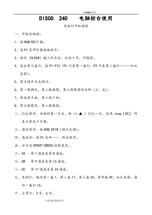
DISCO 240 电脑控台使用电脑灯开机编程一、开机后编程:1、按RUN/EDIT键。
2、选P1至P12健选编程号。
3、按住(CLEAR)键三秒左右,出现﹡字,可编程。
4、选出第几盏灯,按P1-P12(P1代表第一盏灯,P2代表第二盏灯………如此类推)。
5、第4路开光及频闪。
6、第一路换色,第二路换图,第三路图案的自转(正、反)。
7、第五路X轴,第六路Y轴。
8、第七路聚焦,第八路棱镜。
二、记忆程序:当编好每一步后,按(+ ▲)记忆一次,出现step[05],则表示第五个步骤。
三、推出程序:按RVN EPIN(橙红色健)。
四、选程序:按P1或P……..取出程序。
五、右手边SPEEP/CRDSS控制速度。
六、SA 第1通道至第8通道。
七、SB 第9通道至第16通道。
八、SC 第17通道至第24通道。
九、电脑灯:编码第一盏1,第二盏17,第三盏33,第四盏49。
如此类推,每加一盏加16。
十、正常灯:3号,6号。
SD-145电脑控台使用一、第一步:开机后PROGNAM键三秒左右,出现左下角闪烁点,即可编程。
二、第二步:按左手边1-12路选灯(第几盏)选定后。
按MID/ADD键,再按SCENS 1-8 表示第一个动作,一定要编完8个动作,再按回PROGNAM键三秒钟,完成编程。
编第二个程序时,消掉所有绿灯。
即推出所有程序,可以编下个程序,但在BANK按▲选第几程序。
三、可以按CHASE 1键来完成1-2或更多连接。
HPL 灯控台使用一、通过《集控/通道切换》单路及编组控制。
二、先将硅亮的壹路打着,在控台相对应的调光路推子推上。
三、编组:1、按住《集控/通道》切换为单路控制。
2、按住《控》键一下,点击需要编的数字,例如在19路集控红色,点击《控》键,再点击1和9,再按就在19路可以控制红色记录键两下,记录了刚才的编程。
3、调用出编组:控制走灯一、点击编程/通道键,转为编组模式,将已编好的颜色逐个推上。
(例如:需要红、绿、兰、白四色,先将红色推上,点击《效果》,再点击1.1,再点击《记录》两次,再将绿色推上,步骤同上,完成走灯。
智能AVI Advanced 4-Port DP KVM 切换器用户手册说明书

USER MANUALTable of contentTECHNICAL SPECIFICATIONS_____________________________________________________________3 WHAT’S IN THE BOX?_____________________________________________________________________4 SM-DPN FRONT AND REAR______________________________________________________________4 INSTALLATION____________________________________________________________________________5-7 LED’s BEHAVIOR__________________________________________________________________________11 SYSTEM OPERATION______________________________________________________________________12 TROUBLESHOOTING______________________________________________________________________12 TECHNICAL SUPPORT_____________________________________________________________________12 LIMITED WARRANTY STATEMENT________________________________________________________13SM-DPN-4S rear SM-DPN-4S frontinstallationSingle-Head Units:1.Ensure that power is turned off or disconnected from the unit and the computers.e a DP cable to connect the DP output port from each computer to thecorresponding DP IN ports of the unit.e a USB cable (Type-A to Type-B) to connect a USB port on each computer to therespective USB ports of the unit.4.Optionally connect a stereo audio cable (3.5mm to 3.5mm) to connect the audio outputof the computers to the AUDIO IN ports of the unit.5.Connect a monitor to the DP OUT console port of the unit using a DVI cable.6.Connect a USB keyboard and mouse in the two USB console ports.7.Optionally connect stereo speakers to the AUDIO OUT port of the unit.8.Finally, power on the KVM by connecting a 12VDC power supply to the powerconnector, and then turn on all the computers.Note: You can connect up to 2 computers to the 2 port KVM and up to 4 computers to the 4 port KVM.SM-DPN-4S ShownMulti -Head Units:1. Ensure that power is turned off or disconnected from the unit and the computers.2. Use DP cables to connect the DP output ports of each computer to the corresponding DP IN ports of the unit. For example, if using SM -DPN -4Q , the four DP ports of one computer must all be connected to one channel.The DP IN connectors that belong to the same channel are arranged vertically.3. Use a USB cable (Type -A to Type -B) to connect a USB port on each computer to the respective USB ports of the unit.4. Optionally connect a stereo audio cable (3.5mm on both ends) to connect the audio output of the computer to the AUDIO IN ports of the unit.5. Connect the monitors to the DP OUT console ports of the unit using DP cables.The DP IN ports on one row will be switched to the DP OUT of the same row.6. Connect a USB keyboard and mouse in the two USB console ports.7. Optionally connect stereo speakers to the AUDIO OUT port of the unit.8. Power on the KVM by connecting a 12VDC power supply to the power connector, and then turn on all the computers.Installation (continued)SM-DPN-4Q ShownInstallation (continued)EDID Learn:The KVM is designed to learn the connected monitor’s EDID upon power up. In the event of connecting a new monitor to the KVM, a power recycle is required.The KVM will indicate to the user the EDID learn process by flashing the front panel’s LEDs. Port one green and push button blue LEDs will both begin to flash for about 10 seconds. When the LEDs stop flashing, the EDID learn process is done.If the KVM has more than one video board (such as dual-head and quad-head models), then the unit will continue to learn the EDIDs of the connected monitors and indicate the progress of the process by flashing the next port selection green and push button blue LEDs respectively.The monitor must be connected to the video output connector located in the console space at the back of the KVM during the EDID learn process.If the read EDID from the connected monitor is identical to the current stored EDID in the KVM then the EDID learn function will be skipped.System operationThere are three ways to control the SM-DPN: Keyboard Hotkeys, RS-232 Serial Commands, and Front Panel Buttons. All modes of control will allow the user the set their desired configurations. front panel controlThe front panel buttons will function as the typical secure KVM switches. To switch to an input port, simply push the desired input button on the front-panel of the KVM. If an input port is selected, the LED of that port will turn on.There are 4 buttons on the front panel of the device, depending on the model. There will be an added EDID Learn function that can be triggered from the Front Panel, this will be triggered as follows: Hold down the First and Last button of Front Panel for 3 seconds to force Learn EDID. hotkey and rs232 serial controlThe SM-DPN may also be controlled via RS-232 commands. To use these commands, you must use HyperTerminal or an alternate terminal application. The settings for the connection are as follows: Baudrate 115200; Data Bits 8; Parity None; Stop Bits 1; Flow Control None.Once you have connected to the SM-DPN via Serial, you will see the SM-DPN information when the device starts up.The following commands can be used for RS-232 with available keyboard hotkeys:Custom hotkey triggersUsers are able to customize the keys that trigger Hotkeys. The default trigger for hot key function on the Keyboard is Ctrl +Ctrl. The trigger function can be used to change to double Ctrl, Shift, or Scroll Lock.To view hotkey trigger setting:Type on Keyboard: Alt + Alt + Alt + k + 0 + [Enter]The LED Light on the user’s keyboard will Flash indicating which trigger is currently activeNum Lock LED flash indicates CTRLCaps Lock LED flash indicates ShiftScroll Lock LED flash indicates Scroll LockTo change the hotkey trigger setting:Hotkey trigger twice + x + [1 | 2 | 3]1 -Ctrl2 -Shift3 -Scroll LockExample: If the hotkey trigger is Shift and would like to change to Scroll Lock,Type: Shift + Shift + x + 3User Console Interface – Display LED:Front Panel – Port Selection LED ’s:EDID Learn - Front Panel LED ’s:All LED ’s are turned on for 1 second. Then:∙ Port 1 LED ’s will flash until the end of the process.∙ Port 2 LED ’s will flash until the end of the process if a second video board exists (Dual -head KVM) ∙ Port 3 LED ’s will flash until the end of the process if a third video board exists (Quad -head KVM) ∙ Port 4 LED ’s will flash until the end of the process if a fourth video board exists (Quad -head KVM)IMPORTANT!Led ’s behaviorTroubleshootingNo Power∙ Make sure that the power adapter is securely connected to the power connector of the unit.∙ Check the output voltage of the power supply and make sure that the voltage value is around 12VDC.∙ Replace the power supply.No Video∙ Check if all the video cables are connected properly.∙ Connect the computer directly to the monitor to verify that your monitor and computer are functioning properly.∙ Restart the computersKeyboard is not working∙ Check if the keyboard is properly connected to the unit.∙ Check if the USB cables connecting the unit and the computers are properly connected.∙ Try connecting the USB on the computer to a different port.∙ Make sure that the keyboard works when directly connected to the computer.∙ Replace the keyboard.Mouse is not working∙ Check if the mouse is properly connected to the unit.∙ Try connecting the USB on the computer to a different port.∙ Make sure that the mouse works when directly connected to the computer.∙ Replace the mouse.No Audio∙ Check if all the audio cables are connected properly.∙ Connect the speakers directly to the computer to verify that the speakers and the comput-er audio are functioning properly.∙ Check the audio settings of the computer and verify that the audio output is through the speakers.Technical supportFor product inquiries, warranty questions, or technical questions, please contact *****************.Limited warranty statementA.Extent of limited warrantySmartAVI, Inc. warrants to the end-user customers that the SmartAVI product specified above will be free from defects in materials and workmanship for the duration of 1 year, which duration begins on the date of purchase by the customer. Customer is responsible for maintaining proof of date of purchase.SmartAVI limited warranty covers only those defects which arise as a result of normal use of the product, and do not apply to any:a. Improper or inadequate maintenance or modificationsb. Operations outside product specificationsc. Mechanical abuse and exposure to severe conditionsIf SmartAVI receives, during applicable warranty period, a notice of defect, SmartAVI will at its discretion replace or repair defective product. If SmartAVI is unable to replace or repair defective product covered by the SmartAVI warranty within reasonable period of time, SmartAVI shall refund the cost of the product.SmartAVI shall have no obligation to repair, replace or refund unit until customer returns defective product to SmartAVI.Any replacement product could be new or like new, provided that it has functionality at least equal to that of the product being replaced.SmartAVI limited warranty is valid in any country where the covered product is distributed by SmartAVI.B. Limitations of warrantyTo the extant allowed by local law, neither SmartAVI nor its third party suppliers make any other warranty or condition of any kind whether expressed or implied with respect to the SmartAVI product, and specifically disclaim implied warranties or conditions of merchantability, satisfactory quality, and fitness for a particular purpose.C. Limitations of liabilityTo the extent allowed by local law the remedies provided in this warranty statement are the customers sole and exclusive remedies.To the extant allowed by local law, except for the obligations specifically set forth in this warranty statement, in no event will SmartAVI or its third party suppliers be liable for direct, indirect, special, incidental, or consequential damages whether based on contract, tort or any other legal theory and whether advised of the possibility of such damages.D. Local lawTo the extent that this warranty statement is inconsistent with local law, this warrantystatement shall be considered modified to be consistent with such law.NOTICEThe information contained in this document is subject to change without notice. SmartAVI makes no warranty of any kind with regard to this material, including but not limited to, implied warranties of merchantability and fitness for particular purpose. SmartAVI will not be liable for errors contained herein or for incidental or consequential damages in connection with the furnishing, performance or use of this material. No part of this document may be photocopied, reproduced, or translated into another language without prior written consent from SmartAVI, Inc.20180109T el: (800) AVI-2131 • (702) 800-00052455 W Cheyenne Ave, Suite 112North Las Vegas, NV 89032。
DMX 2401 2042 240 通道 控台使用说明
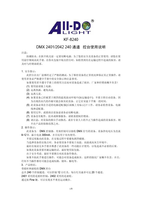
KF-8240DMX 2401/2042 240通道控台使用说明注意:防潮防水,在拆开机壳前一定要切断电源,为了您的安全及设备的正常使用,请您在使用前仔细阅读此手册。
在你从包装中取出控台时,如检查到有在运输过程中造成的损害,请及时与经销商联系。
1. 安全指示:此控台在出厂前都经过了严格的测试,为了维持设备的正常状况和保证其正常操作,请使用者务必严格遵守手册中的安全指示和注意事项。
如果使用者不遵守手册上的使用方法而对设备造成了损害,厂家和经销商概不负责!(1) 使用前请接上电源。
(2) 远离热源,避免高温。
(3) 远离儿童。
(4) 如果设备已经被置于剧烈的温度波动环境中(如运输途中),不要立即启动设备,因为出现的水汽的冷凝可能会损害此设备,让它在室温下平衡一段时间。
(5) 此设备必须在合适的电源适配器(后面板上有标示)下工作,请务必检查设备,电源线和适配器。
(6) 使用完毕,或要清洁设备前请务必切断电源。
(7) 设备没有配件,技术或维修服务,请联系授权经销商。
(8) 请注意:对设备的擅自手动修改,或非专业人士的不正当操作造成的设备损害,则不在产品的保修范围之内。
2. 操作指示:此设备为一DMX控制器,用来控制可以接收DMX信号的设备。
设备供电电压为直流9-12 V,最小电流300mA,并且仅用于室内使用。
不要过度振动此设备,在安装过程中要避免剧烈碰撞。
当选择设备的安装点时,务必使设备不要处于高温,高湿或高灰尘环境中。
最好在阅读完本手册并熟悉了此设备的一些功能后才使用,以免造成不必要的后果。
如果此设备需要再被运输的话,最好使用原包装。
出于安全考虑,最好不要擅自对此设备作修改。
如果不按此手册进行操作,可能会对设备造成损害,这样的情况厂家概不负责,并且,任何不当操作都有可能会造成短路,烧坏,触电等。
3.产品特征:带摇杆和滚轮的DMX控台总共240个控制通道,可以控制12台灯具,每台灯具最多可达20个通道。
HDNET-4P 四路HDMI自动切换器用户手册说明书
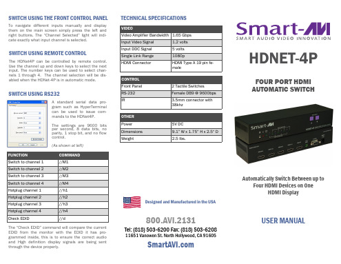
TECHNICAL SPECIFICATIONS
VIDEO
Video Amplifier Bandwidth 1.65 Gbps
Input Video Signal
1.2 volts
Input DDC Signal
5 volts
Single Link Range
1080p
HDMI Connector
3. Optionally connect RS-232 for control functions. 4. Connect the display monitor to the HDMI OUT on
the HDNET-4P. 5. Power on the HDNET-4P.
LEARNING EDID
The HDNet-4P offers an automatic switching mode, and when configured as an automatic switcher, it has the ability to switch to a selectable secondary input upon powering off of the primary input. HDNet4P will automatically switch to the next device when the higher input is powered off. This allows the user to control multiple devices with the HDNet-4P.
FOUR PORT HDMI AUTOMATIC SWITCH
Automatically Switch Between up to Four HDMI Devices on One HDMI Display
240调光台说明书
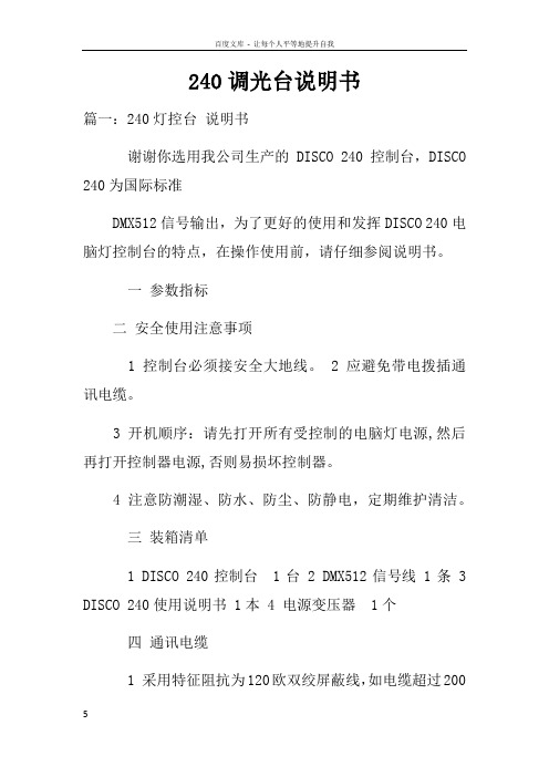
240调光台说明书篇一:240灯控台说明书谢谢你选用我公司生产的DISCO 240控制台,DISCO 240为国际标准DMX512信号输出,为了更好的使用和发挥DISCO 240电脑灯控制台的特点,在操作使用前,请仔细参阅说明书。
一参数指标二安全使用注意事项1 控制台必须接安全大地线。
2 应避免带电拨插通讯电缆。
3 开机顺序:请先打开所有受控制的电脑灯电源,然后再打开控制器电源,否则易损坏控制器。
4 注意防潮湿、防水、防尘、防静电,定期维护清洁。
三装箱清单1 DISCO 240控制台 1台2 DMX512信号线 1条3 DISCO 240使用说明书 1本4 电源变压器 1个四通讯电缆1 采用特征阻抗为120欧双绞屏蔽线,如电缆超过200米或灯数量较多,应加信号提升放大器,并在最后一台灯加接终端电阻(120欧/1W)。
2 通讯电缆1脚为地(GND),2脚为信号正,3脚为信号负,在使用过程中不可接反接错。
3 通讯电缆应单端接地屏蔽。
4 通讯电缆应避免同强电一齐布线。
五 DMX512地址分配DISCO 240控制台使用DMX512的1~240通道,其中1~192路为控制电脑灯用通道,可以控制16通道以内的电脑灯12台,从193开始为调光器用通道,地址分配如下:六通讯电缆连线及电脑灯地址码示意图注:当信号连接电缆过长时,需要加DMX信号放大器,并且在最后一台灯的信号座,加信号终端电阻(120欧/1W)七面板及功能区域图八面板功能区域说明九双功能键区说明篇二:240灯控台_说明书一参数指标五 DMX512地址分配DISCO 240控制台使用DMX512的1~240通道,其中1~192路为控制电脑灯用通道,可以控制16通道以内的电脑灯12台,从193开始为调光器用通道,地址分配如下:六通讯电缆连线及电脑灯地址码示意图注:七面板及功能区域图当信号连接电缆过长时,需要加DMX信号放大器,并且在最后一台灯的信号座,加信号终端电阻(120欧/1W)八面板功能区域说明九双功能键区说明篇三:调光台型号DISCO24016CH24DM512说明书调光台型号DISCO240,16CH*24DM*512说明书一;电脑灯的程序场编辑1.按(BLACK)键使该LED指示灯熄灭2.按(DEIT\RUN)键使该LED指示灯亮,进入编程状态3.按数字键(P1—P12)中任意一次,选择要编程的程序场编号,显示在LED的CHASE括号中。
无线模块2401调试方法(C51)
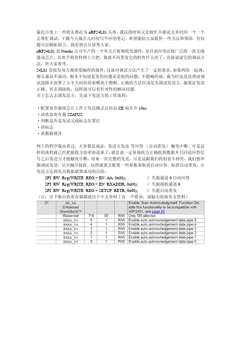
//*************************************SPI(nRF24L01)寄存器地址**************************************************** #define CONFIG #define EN_AA #define EN_RXADDR #define SETUP_AW #define SETUP_RETR #define RF_CH #define RF_SETUP #define STATUS #define OBSERVE_TX #define CD #define RX_ADDR_P0 #define RX_ADDR_P1 #define RX_ADDR_P2 #define RX_ADDR_P3 #define RX_ADDR_P4 #define RX_ADDR_P5 #define TX_ADDR #define RX_PW_P0 #define RX_PW_P1 #define RX_PW_P2 #define RX_PW_P3 #define RX_PW_P4 #define RX_PW_P5 #define FIFO_STATUS 0x00 0x01 0x02 0x03 0x04 0x05 0x06 0x07 0x08 0x09 0x0A 0x0B 0x0C 0x0D 0x0E 0x0F 0x10 0x11 0x12 0x13 0x14 0x15 0x16 0x17 // 配置收发状态,CRC 校验模式以及收发状态响应方式 // 自动应答功能设置 // 可用信道设置 // 收发地址宽度设置 // 自动重发功能设置 // 工作频率设置 // 发射速率、功耗功能设置 // 状态寄存器 // 发送监测功能 // 地址检测 // 频道 0 接收数据地址 // 频道 1 接收数据地址 // 频道 2 接收数据地址 // 频道 3 接收数据地址 // 频道 4 接收数据地址 // 频道 5 接收数据地址 // 发送地址寄存器 // 接收频道 0 接收数据长度 // 接收频道 0 接收数据长度 // 接收频道 0 接收数据长度 // 接收频道 0 接收数据长度 // 接收频道 0 接收数据长度 // 接收频道 0 接收数据长度 // FIFO 栈入栈出状态寄存器设置
Datavideo SE-500 4-通道混音器 切换器说明书
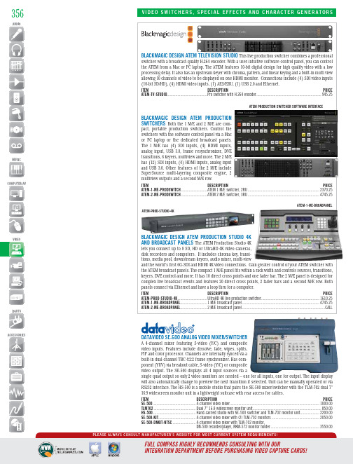
datavideo Se-500 analog video mixer/Switcher A 4-channel mixer featuring S-video (Y/C) and composite video inputs. Features include dissolve, fade, wipes, splits, PIP and color processor. Channels are internally synced via a ponent (YUV) via breakout cable, S-video (Y/C) or composite video output. The SE-500 displays all 4 input sources via asingle quad output so only 2 video monitors are needed – one for all inputs, one for output. The input display Blackmagic deSign atem televiSion Studio This live production switcher combines a professionaloduction pact, portable production switchers. Control the switchers with the software control panel via a Mac or PC laptop or the dedicated broadcast panels. The 1 M/E has (4) SDI inputs, (4) HDMI inputs, analog input, USB 3.0, frame resynchronizer, DVE transitions, 6 keyers, multiview and more. The 2 M/E has (12) SDI inputs, (4) HDMI inputs, analog input and USB 3.0. Other features of the 2 M/E include SuperSource multi-layering composite engine, 2 Blackmagic deSign atem Pr oduction Studio 4k The ATEM Production Studio 4K lets you connect up to 8 SD, HD or UltraHD 4K video cameras, tions, media pool, downstream keyers, audio mixer, multi-viewand the world’s first 6G-SDI and HDMI 4K video connections. Gain greater control of your ATEM switcher with atem-1-me-BroadPanelatem Production Switcher Software interfaceatem-Prod-Studio-4kFor expert advice - call: 800-356-5844M-F: 9:00-5:30 CentralDataViDeO Se-2000 HD-SDi This unit fea-tures 13 transitions with border, 5 indi-vidual speed keys (for instant selection with take effect), and the ability to insert up to 14 pre-stored logos. Includes 3 dedicated HD-SDI inputs, 1 DVI-D input andDataViDeO HS-2000 MObile ODuctiOn StuDiO/This unit features a 17" LCD monitor to display multiview out-puts, 1 DVI-D input, 3 HD-SDI inputs and 1 selectable DVI-D/HD-SDI input, a built-in 4-channel audio mixer, a 5-channel wired intercom with belt packs for camera ops. Monitor shows review input, program output, and picture-in-picture preview. Program output allows connection to external digital video recorder, which can be viewed on the unit’s screen. Also features luma key, built-in TBC and frame synchronizerson all inputs, and HD resolutions up to 1920x1080i DataViDeO Se-900 SD SwitcHeR SySteM This 8-input SD switch-er has an expand-able core feature set that includeschroma key cards and PIP. This2-piece switcher (control panel andrack mounted processor) is ideal for SD venues.The switcher accepts a mix of 8 input cards for DV, SDI,DVI, YUV and composite. Outputs include DV, SDI, composite,358Follow Us!inteliX HDMi/HDbaSet MatRiX SwitcHeRS Each output port allows the same signal to be routed to the HDMI connector and to a remote destination with an HDBaseT receiver. The HDBaseT ports support 1080p HDMI video with audio, bi-directional wide-band IR, HDCP, and matrix control via IR. Additional features include 2K resolution support, Deep Color, full 3D capabilities, control via IP, RS-232, IR, or front panel, and a full command set for RS232 and Ethernet control via 3rd party systems. Comes with an IR remote control that allows IR switching, IR eyes, and IR emitters.ITEM DE S CRIPTION PRICE DIGI-44B ........4 in/4 out HDMI/HDBaseT Matrix Switcher with 4 routing presets ........1764.00DIGI-88B ........8 in/8 out HDMI/HDBaseT Matrix Switcher with 8 routing presets ..............CALLinteliX FlX-8X8a MODulaR FleX MatRiX SySteM The FLX-8X8A is a card-based matrix distribution system, consisting of two input and two output slots. Insert any combination of HDMI, DVI, VGA, Y/Pb/Pr Component Video, and/or HDBaseT input cards with HDMI, DVI, and HDBaseT output cards. Use any input type with any output type. This matrix can drive both local and remote zone outputs via twisted-pair cabling. In addition to modules, the unit has built-in RS232 and ethernet connectors, front panel control, EDID management, and a 8x8 balanced stereo audio switcher for whole premise audio capabilities.ITEM DE S CRIPTION PRICE FLX-8X8A ..................8x8 flex matrix distribution system ...........................................4595.47FLX-HI4.....................4-port HDMI input card ...............................................................576.07FLX-DI4.....................4-port DVI input card ..................................................................576.07FLX-RI4.....................4-port RGB, YUV, SV, YC, CV scaling input card .......................1876.67FLX-BI4.....................4-port HDBaseT input card .......................................................1803.87FLX-HO4....................4-port HDMI output card .............................................................576.07FLX-DO4....................4-port DVI output card ................................................................576.07FLX-BO4....................4-port HDBaseT output card .....................................................1803.87Digi-88bPrices subject to change without notice. Call today or visit us online!HORita Kct-50cHaRacteR geneRatOR A stand-alone video charac-ter generator with built-in text editor, that works with a standard PC keyboard (no PC required) to superimpose captions and titles of up to nine lines of 20 characters each, on analog composite video. The horizontal and vertical size and position,black/white, mask on/off, and contrast for the characters is user adjustable. Date and time information can also be automatically inserted in a variety of formats. Up to 25 KCT-50s can be connected and controlled from a single PC keyboard.ITEM DE S CRIPTION PRICE KCT50........................Character generator ....................................................................379.28359A complete portable HD studio ina single unit. Single-person oper-ation of sound and picture using fad-ers, buttons and touch screen. Integratesan audio mixer, video switcher, multi-viewer touchscreen and USB video/audio streaming into a stand-alonedevice. Supports 12 input, 4-Channel video plus still channel for PanaSOnic aV-HS410 HD/SD SMaRt SwitcHeR This powerful, easy-to-usePanaSOnic ag-HMX100 Digital a/V MiXeR Integrating a HD/SD videoFORMat liVe HD/SD SwitcHeRThis half-rack unit-wide, 4:2:2 HD/SDing, built-in MultiViewer (4, 9, or 10images on a single display), chromakeyer, aux bus with an IP link toPanasonic's AWRP50 remote cameraLooking forvideoconverters?See pages364-368®gen10cOnVMaaS2360Follow Us!tV One S2 SwitcHeR/inPut eXPanSiOn MODuleS Any of the S2 Series can be used as standalone video and audio switcher or as expansion module for the C2 Scaler/Switcher Series. Only one S2 unit can be attached to a C2 product, but several S2 units can be daisy-chained to each other.ITEM DE S CRIPTION PRICE S2-101AA ..................1x2 audio power amplifier ...........................................................335.75S2-105CV ..................5x2 composite video switcher .....................................................250.75S2-105CVA ................5x2 composite video/audio switcher ...........................................335.75S2-105DVIA ...............5x1 DVI-D and stereo audio switcher ..........................................845.75S2-105PC ..................5x1 RGB/YPbPr switcher ..............................................................505.75S2-105PCA ................5x1 RGB/YPbPr switcher and stereo audio switcher ....................675.75S2-105YC ..................5x2 YC (S-Video) switcher ...........................................................250.75S2-105YCA ................5x2 YC (S-Video) and stereo audio switcher ...............................335.75S2-106AD ..................6x2 stereo audio switcher with full processing ...........................845.75S2-108HD ..................8x2 HD/SD-SDI routing switcher ................................................1440.75S2-109PC ..................9x1 RGB/YpbPr switcher ..............................................................675.75S2-110CV ..................10x2 composite video switcher ...................................................505.75S2-110YC ..................10x2 YC (S-Video) switcher .........................................................420.75S2-105PcaSOny McS-8M Multi-FOR Mat cOMPact SwitcHeR A multi-format switcher with a built-in audio mixer and a frame synchronizer. Features include preset DME wipe patterns, multi-viewer, keyer, 1-channel frame memory input, and a 3D Mode function. It operates in either HD or SD mode with the following inputs - (4) HD/SD-SDI, (3) HDMI (HD only), (3) analog composite (SD only) and (1) DVI-I. The 6-channel audio mixer has audio delay adjustment, a USB port and (2) XLR and (4) TRS outputs.ITEM DE S CRIPTION PRICE MCS-8M pact audio/video mixing switcher ............................................CALLOlanD V1600HD Ideal in live events or ing a high channel count and the ability to accept a variety of video input formats out of the box. All-in-one 14-channel (16-input) seamless switcher/mixer. Connect HS/SD-SDI x8, DVI-D x2, RGB x2, component x2,S-Video, and composite inputs. Also input still from a USB thumb drive. Output-3eX web 4-input video mixer with less switcher/mixer. input formats areOSS ViDeO cR OSSOVeR SOlO Multi-DeFinitiOn PR ODuctiOn SwitcHeR The CrossOver Solo is a powerful, all-in-one production switcher that fits small spaces and budgets. The main electronics and signal I/O are combined within the panel as a single unit. Features include a built-in multiviewer, input syn-chronization, (4) media store channels, chroma keyer, reference generator, robotic camera control and a rugged all metal construction. The unit has (10) source buttons, (12) HD-SDI inputs, (3) AUX bus outputs, (1) HD-SDI preview output and (2) HD-SDI program outputs.ITEM DE S CRIPTION PRICE CROSSOVER-SOLO .....All-in-one video switcher .................................................................CALLOur Sales Pros will provide you with the solutions you need.。
MCB240 快速使用指南说明书
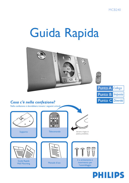
Antenna a
T-sfohrmaapdei TAntenna
Speaker Altoparlante (destro)
2
(right)
SpAletoapakrleanrte (sinistro) (left)
3
AC Cavp do paliomewntaezironecion cr.ad.
Tips
– Se la ricezione è scarsa, stendere un'estremità dell'antenna a T e tenere l'altra estremità ad angolo orizzontale rispetto alla prima. – Leggere il Manuale d'uso per maggiori istruzioni sulle funzioni DAB.
selezionare CD o premere CD sul telecomando.
2 Premere OPEN•CLOSE 0 sul pannello frontale del
sistema per aprire il piatto dei CD.
3 Inserire un disco con il lato stampato rivolto verso l'alto. Premere di nuovo OPEN•CLOSE 0 per chiudere il piatto.
finché "--:--" lampeggia sul display per impostare la normale modalità standby.
G120 CU240BE-2简明调试手册4005
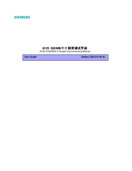
3.1 使用操作面板 BOP-2 调试 .................................................................................................................................13 3.2 STARTER 软件调试............................................................................................................................................21
第三章 调试工具介绍...................................................................................................................................................13
2.1 PM240 功率模块接线图........................................................................................................................................7 2.2 控制单元安装与接线 ............................................................................................................................................8
矩阵切换器说明书.(DOC)
shProfessional Matrix矩阵切换器用户手册在使用本系统前,请详细阅读本说明书.并请保管好该手册目录前言 (4)一、清单、外形及安装说明 (5)1、包装清单 (5)2、普通矩阵前后面板 (6)3、数模高清混插矩阵前面板 (7)4、机架安装说明 (10)二、功能特点及主要技术指标 (11)一、普通矩阵 (11)1、功能与用途 (11)2、主要技术指标 (11)二、数模高清混插矩阵 (12)3、功能与用途 (12)2、主要技术指标 (13)三、系统连接图 (15)四、矩阵的操作 (16)1、指示灯及面板按键 (16)2、遥控器的使用 (19)3、显示屏及显示的画面 (20)4、菜单总表及一般操作方法 (22)5、各菜单说明 (24)6、矩阵的切换 (33)7、控制软件 (35)五、注意事项及故障处理 (52)1、注意事项 (52)2、常见故障检修 (52)附录A、串口控制协议 (53)1、通信接口 (53)2、控制命令 (54)附录B、编程说明 (61)1、用 VB 编程控制矩阵 (61)2、用 VC 编程控制矩阵 (62)3、用C# 编程控制矩阵 (64)4、用 Delphi 编程控制矩阵 (66)前言感谢您使用本公司矩阵切换器,使用时请注意以下事项:1.本产品所使用电源必须有电源保护地线,输入、输出设备的电源保护地线要为同一保护地线。
确保设备的输入电源为AC 100~240V/50Hz。
2.使用计算机控制本产品时必须保证控制计算机与本产品的连接电源保护地线是同一个地线。
3.使用本产品时严禁带电插拔输入、输出信号线及RS232 通讯接口线。
4.严禁将本产品放在过热或过冷的地方工作,应保持工作环境通风良好。
严禁将化学物品洒在本产品上。
5.严禁对本产品的机械和电路设计进行更改或增减任何部件,否则厂家对此产生的任何结果不负责任。
6.严禁擅自打开机箱外壳,机器内有交流220V 高压,以免发生触电危险。
电子切换器组件和配件说明书
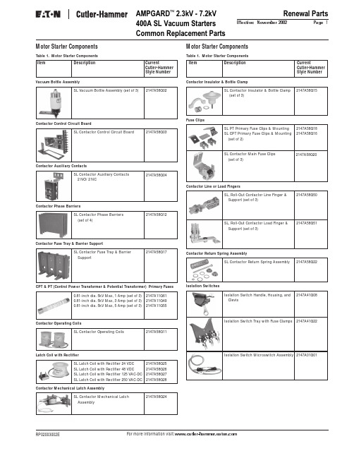
For more information visit: AMPGARD 2.3kV - 7.2kV 400A SL Vacuum StartersCommon Replacement PartsRenewal PartsPage 1Effective: November 2002RP02003002E SL Vacuum Bottle Assembly (set of 3)SL Contactor Control Circuit BoardSL Contactor Auxiliary Contacts 2 NO/ 2 NC0.81-inch dia. 5kV Max, 1 Amp (set of 3)0.81-inch dia. 5kV Max, 3 Amp (set of 3)0.81-inch dia. 5kV Max, 5 Amp (set of 3)SL Contactor Return Spring AssemblySL, Roll-Out Contactor Line Finger & Support (set of 3)SL, Roll-Out Contactor Load Finger & Support (set of 3)Isolation Switch Tray with Fuse Clamps 2147A58G022147A58G032147A58G042147A58G122147A11G612147A11G492147A11G552147A58G152147A58G182147A58G162147A58G172147A58G202147A58G222147A58G502147A58G512147A41G222147A01G01SL Latch Coil with Rectifier 24 VDC SL Latch Coil with Rectifier 48 VDC SL Latch Coil with Rectifier 125 VAC-DC SL Latch Coil with Rectifier 250 VAC-DC2147A58G252147A58G262147A58G272147A58G28SL Contactor Operating Coils2147A58G11Contactor Operating CoilsSL Contactor Mechanical Latch Assembly2147A58G24Motor Starter ComponentsTable 1. Motor Starter ComponentsItem DescriptionCurrentCutler-Hammer Style NumberMotor Starter ComponentsTable 1. Motor Starter ComponentsItem DescriptionCurrentCutler-Hammer Style NumberVacuum Bottle AssemblyContactor Control Circuit BoardContactor Auxiliary ContactsContactor Phase BarriersCPT & PT (Control Power Transformer & Potential Transformer) Primary FusesContactor Insulator & Bottle ClampFuse ClipsContactor Fuse Tray & Barrier SupportContactor Return Spring AssemblyContactor Line or Load FingersIsolation SwitchesSL Contactor Phase Barriers (set of 4)SL Contactor Insulator & Bottle Clamp (set of 3)SL PT Primary Fuse Clips & Mounting SL CPT Primary Fuse Clips & Mounting (set of 2)SL Contactor Fuse Tray & Barrier SupportSL Contactor Main Fuse Clips (set of 3)Isolation Switch Microswitch Assembly Latch Coil with RectifierContactor Mechanical Latch AssemblyIsolation Switch Handle, Housing, and Clevis2147A41G08Renewal PartsPage 2Effective: November 2002AMPGARD 2.3kV - 7.2kV 800A SJ Vacuum Starters Common Replacement PartsEaton CorporationCutler-Hammer business unit 1000 Cherrington ParkwayMoon Township, PA 15108-4312USAtel: 1-800-525-2000© 2002 Eaton Corporation All Rights Reserved Printed in USAForm No. RP02003002E November 2002Contactor CoilMagnet AssemblyBarrier AssembliesVacuum Bottle with Shunt, Support, & FingersIsolation SwitchesMiscellaneous Parts KitFuse PullerContactor Tune-up KitInterlocksL-63 Interlock (coil circuit)578D461G03L-64 Auxiliary Interlocks 1 NO 1 NC L-64 Auxiliary Interlocks 2 NO L-64 Auxiliary Interlocks 2 NC843D943G21843D943G22843D943G23Load or Line FingersMotor Starter ComponentsTable 1. Motor Starter Components800A Contactor Coils 120 VAC (set of 2)800A Contactor Coils 240 VAC (set of 2)800A Contactor Magnet Assembly with Coil 120 VAC800A Contactor Magnet Assembly with Coil 240 VAC800A Contactor Magnet Assembly without Coil800A Contactor Barrier Assembly800A Contactor Fuse Support & Barrier Assembly800A Contactor Fuse Load Fingers (between contactor & fuse) (set of 3)800A Contactor Line Fingers with Copper Support800A Contactor Line or Load Fingers without Copper Support2147A89G022147A89G012147A71G152147A89G062147A89G072147A88G022147A88G032147A88G042147A88G112147A88G12800A Contactor Miscellaneous Parts Kit 2147A88G15800A Contactor Fuse Puller2147A93G07800A Isolation Switch Handle, Housing, & Clevis2147A71G08800A Isolation Switch Tray Assembly with Line Fingers2147A81G22800A Contactor Tune-up Kit2147A99G042147A01G01Isolation Switch Microswitch Assembly Note: For additional information, call 1-800-523-3775.Motor Starter ComponentsTable 1. Motor Starter ComponentsCPT & PT (Control Power Transformer & Potential Transformer) Primary Fuses0.81-inch dia. 5kV Max, 1 Amp (set of 3)0.81-inch dia. 5kV Max, 3 Amp (set of 3)0.81-inch dia. 5kV Max, 5 Amp (set of 3)2147A11G612147A11G492147A11G551.00-inch dia. 5kV Max, 1 Amp (set of 3)1.00-inch dia. 5kV Max, 3 Amp (set of 3)1.00-inch dia. 5kV Max, 5 Amp (set of 3)2147A11G632147A11G462147A11G53800A Contactor Vacuum Bottle with Shunt, Support & Fingers (set of 3)2147A87G03Item DescriptionCurrentCutler-Hammer Style NumberItem DescriptionCurrentCutler-Hammer Style Number。
PR-0402 精细 4x2 4K60 HDMI 切换器快速入门指南说明书

© 2021 Harman. All rights reserved. SmartScale, NetLinx, Enova, AMX, AV FOR AN IT WORLD, and HARMAN, and their respective logos are registered trademarks of HARMAN. Oracle, Java and any other company or brand name referenced may be trademarks/registered trademarks of their respective companies.AMX does not assume responsibility for errors or omissions. AMX also reserves the right to alter specifications without prior notice at any time. The AMX Warranty and Return Policy and related documents can be viewed/downloaded at .3000 RESEARCH DRIVE, RICHARDSON, TX 75082 | 800.222.0193 | 469.624.8000 | +1.469.624.7400 | fax 469.624.71531000364570 REV: A Last Revised: 2021-06-24QUICK START GUIDE PR-0402 Precis 4x2 4K60 HDMI SwitcherOverviewThis guide pertains to the PR-0402 Precis 4x2 4K60 HDMI Switcher. The purpose of this document is to illustrate how the device is to be installedand set up in its simplest configuration by a trained technician.What’s in the boxThe following items are included with the PR-0402• [1] 12V/3A DC Power Adapter• [1] US Pins• [1] EU Pins• [1] UK Pins• [1] AU Pins• [3] 3-Pin Terminal Blocks• [4] Rubber FeetPowerActive power requirements:• Voltage, DC: 12V/3A• Power consumption (max): 9.8WEnvironmental RequirementsThe environmental requirements for the PR-0402 are as follows:• Operating Temperature: 32˚F (0˚C) to 104˚F (40˚C)• Storage Temperature: -4°F (-20°C) to 140°F (60°C)• Operating Humidity: 5% to 90% (RH (non-condensing)• Storage Humidity: 5% to 90% (RH (non-condensing) Installation1. Attach the proper cables from HDMI video source (such as a PC,Blu-ray player, game console, satellite/cable box, media server, etc.) to HDMI Input 1 on the 4x2 HDMI matrix switcher. Continue for HDMI Input 2-4.2. Attach the proper cables from the HDMI matrix switcher HDMIOutputports to displays, projectors or other sink devices.3. If required, connect an AV receiver, amplifier or other audio devicetothe audio output port on the PR-0402.4. Power on PR-0402 using the correct DC power cable (supplied in thebox) that meets your location’s requirements Switching OperationPR-0402 supports Auto switching and Manual control modes. Auto switching can be enabled or disabled using the AUTO button on the front panel, API Commands, or via the on-board web interface.A. When Auto switching is enabled, the unit automatically switchesfollowing the rules below:1. If more than one input port has an active signal when the switcherboots, the priority order is: HDMI1 => HDMI2 => HDMI3 => HDMI42. When a new active signal is connected to an input, that input willbe routed to both outputs.3. If the currently routed input is removed, the previous mostrecently selected input will be routed to both outputs.B. Manual switching is allowed only when Auto switching is disabled. Tomake a switch using manual mode:1. Press the appropriate Output Select Button2. Press the appropriate Input Select ButtonMounting Options (Rack Trays and Mounting Brackets) The PR-0402 can be mounted using V Style Surface Mounting Brackets, V Style Single Module Pole Mounting Kit, or the NMX-VRK V-Style Rack Shelf. For details, see .Identify the IP address of the PR-0402Press the RESET ID button twice to show the OSD INFO, and then the current IP address will be presented on the displays connected to the HDMI OUT ports.AMX Precis PR-Series Matrix Switcher Instruction Manual Additional documentation for this device is available at . Refer to the Instruction Manual - Precis PR-Series Matrix Switchers for additional details on installing, upgrading, and controlling the device.See the Important Safety Instructions, available to view or download from the .Consultez les Instructions de sécurité importantes, disponibles pour consultation ou téléchargement sur le site .。
路由器和通道调试手册

Use, duplication, or disclosure by the Government is
subject to restrictions as set forth in subparagraph
(c) of the Commercial Computer Software - Restricted
password casco//远程telnet登录密码
login
!
end
wri mem//保存路由器配置
2.修改完标准配置文件后,请采用上面步骤粘贴到路由器中,然后重新启动路由器,出现“xxx>”提示后,输入“en”,输入密码“casco”,进入配置模式,“xxx#”,其中“xxx”可以是任何字符。
#wri mem
4.网络命令
任务命令
登录远程主机telnet hostname|IP address
例:#telnet 172.20.50.1
网络侦测ping hostname|IP address
例:#ping 172.20.50.1
路由跟踪trace hostname|IP address
例:#trace 172.20.50.1
(1)路由器为新的(未曾设置过)
System Bootstrap, Version 12.0(3)T, RELEASE SOFTWARE (fc1)
Copyright (c) 1999 by cisco Systems, Inc.
C1700 platform with 32768 Kbytes of main memory
1 FastEthernet/IEEE 802.3 interface(s)
TC240 安装手册和操作说明说明书

Installation Manual and Operating InstructionsModel TC240DC/DC Power ConverterTrue Blue Power®is a division of Mid-Continent Instrument Co., Inc.Mid-Continent Instrument Co., Inc.dba Mid-Continent Instruments and Avionics9400 E. 34th Street N.FOREWORDThis manual provides information intended for use by persons who, in accordance with current regulatory requirements, are qualified to install this equipment. If further information is required, please contact:True Blue Powerc/o Mid-Continent Instrument Co., Inc.Attn: Customer Service Dept.9400 E. 34th Street N.Wichita, KS 67226 USAPH (316) 630-0101FX (316) 630-0723We welcome your comments concerning this manual. Although every effort has been made to keep it free of errors, some may occur. When reporting a specific problem, please describe it briefly and include the manual part number, the paragraph/figure/table reference and the page number. Send your comments to:True Blue Powerc/o Mid-Continent Instrument Co., Inc.Attn: Technical Publications9400 E. 34th Street N.Wichita, KS 67226 USAPH (316) 630-0101FX (316) 630-0723All products produced by Mid-Continent Instrument, Co., Inc., including those identified as Mid-Continent Instruments and Avionics or True Blue Power, are designed and manufactured in Wichita, KS, USA.Copyright 2016Mid-Continent Instrument Co., Inc.REVISION DETAILRevision Date Approved DetailA 05/23/16 SHO Initial releaseB 06/22/16 KJW Corrected typo, page 12, 4.2.3, ‘maximum.’5.2 Environmental Qualification Statement:∙ Section 4, changed from F2 to F1;∙ Section 4.5.1 Operating Low Temp changed from -55C to -40C∙ Section 4.5.3 Operating High Temp changed from+70C to +55C.C 12/02/2016 KJW Corrected description, Figure 3.3. Revised theEnvironmental Qualification Statement table forTemperature and Altitude, Section 4.D 10/24/17 KJW Changed Environmental Qualification Statement to add helicopter vibe levels.TABLE OF CONTENTSSECTION 1 GENERAL DESCRIPTIONINTRODUCTION 51.1SPECIFICATIONS 5 TECHNICAL1.2SECTION 2 INSTALLATION CONSIDERATIONS2.1 COOLING 6LOCATION 62.2EQUIPMENT2.3 ROUTING OF CABLES 62.4LIMITATIONS 6SECTION 3 INSTALLATION PROCEDUREINFORMATION 7 GENERAL3.13.2 UNPACKING AND INSPECTING EQUIPMENT 73.3 CABLE HARNESS 7Selection 7 GaugeWire3.3.1Information 7 AssignmentPin3.3.2HarnessVerification 83.3.3Adjustment 8 VoltageOutput3.3.43.4 MOUNTING 103.5CAUTION 10 INSTALLATION10COMPLETIONINSTALLATION3.6SECTION 4 OPERATION11PERFORMANCEELECTRICAL4.1FEATURES 12 PROTECTIVE4.2On/Off 124.2.1Remote12Limit4.2.2VoltageInput12Over-Temperature4.2.3Over-Current 12 Circuitand4.2.4ShortSECTION 5 CONFORMANCE5.1 INSTRUCTIONS FOR CONTINUED AIRWORTHINESS 1313STATEMENT5.2ENVIRONMENTALQUALIFICATIONSECTION 1 GENERAL DESCRIPTION1.1 INTRODUCTIONThe model TC240 DC/DC Power Converter is a lightweight power converter that translates a direct current (DC) input of 28 volts to an adjustable 5 to 18 volt direct current (DC) output.The input operating voltage (24–32VDC) makes the TC240 suitable for nearly any common general, business, or commercial aviation application and provides an adjustable DC output voltage of 5 to18VDC. The unit is rated for a nominal output of 240 watts to power avionics, instrumentation, personal charging, lighting, and many other applications. The TC240 DC/DC Converter is FAA certified to TSO-C71 and tested to rigorous environmental standards and levels of RTCA DO-160G. The small size and light weight in conjunction with its installation flexibility (inside or outside the pressure vessel) make it an ideal choice for aircraft power needs while reducing the challenges associated with other similar products.Highlighted features include short circuit protection, overload capability, low input voltage shut-down, temperature monitoring, reverse polarity protection, a self-resettable over-temperature disable and an optional remote enable (on/off) feature.The TC240 DC/DC converter has a robust Military-rated circular connector and a rugged aluminum case which dissipates heat and provides excellent mechanical strength. It is engineered to require no external cooling and contains no internal fans or cooling methods, which saves energy, reduces weight and allows more flexible installation locations. At only 0.70 pounds, it is lighter and smaller than any other certified solution in the aviation market today.1.2 TECHNICALSPECIFICATIONSElectrical Attributes:Input Voltage: Rated 28VDC nominal, Operating 24 – 32VDC.Input Current (full load): 10 amps max at nominal input voltageOutput Voltage 5 – 18VDC adjustableOutput Power: 240 watts nominalEfficiency: 95%nominalTable 1.1Physical Attributes:Weight: 0.70 lbs (0.32 kg)Dimensions:(not including connector mate) 2.75 inches long x 3.75 inches wide x 1.29 inches high (69.9 mm long x 95.3 mm wide x 32.8 mm high)Mating Connector Kit: 6430240-1 MCIA P/N 9018654 6430240-2 MCIA P/N 9018655Mounting: Base mount – orientation not criticalTable 1.2Qualifications:Certification: FAATSO-C71Environmental Qualification: RTCA DO-160G Environmental Category; See Section 5.2 Altitude: -15,000 feet to +55,000 feetTemperature: -55°C to +70°C (-67°F to +158°F)Table 1.3SECTION 2 PRE-INSTALLATION CONSIDERATIONS2.1 COOLINGThe TC240 product does not require external cooling or contain internal active cooling. Cooling of the unit occurs exclusively through passive conduction through the base or radiated cooling across the metal case. Additional cooling can be realized through convection (exposure to free moving air) or conduction (mounting to a thermally conductive metal surface). These methods are not required to achieve rated performance but can help prevent potential overheating and extend life when the unit is operated at full power or during overload conditions. Specifically, mounting the unit to a metal surface is preferred, but not required.2.2 EQUIPMENTLOCATIONThe TC240 is designed for mounting flexibility, allowing for installation inside or outside the pressure vessel with no requirement for temperature control. In addition to altitude and temperature resistance, the unit is also designed to withstand high levels of condensing humidity. However, installation locations where the unit could be subject to standing or direct water exposure should be avoided. The unit can be mounted in any orientation. Clearance should be provided for the mating connector and may require as much as five inches past the unit connector to allow for back shell access to the connector.OFCABLES2.3 ROUTINGThe wires and cable bundle associated with the unit are heavy gauge wire and carry significant power. Be aware of routing cables near other electronics or with other wire bundles that may be susceptible to high energy flow.Avoid sharp bends in cabling and routing near aircraft control cables. Also avoid proximity and contact with aircraft structures, avionics equipment, or other obstructions that could chafe wires during flight and cause undesirable effects.2.4 LIMITATIONSThe conditions and tests for TSO approval of this article are minimum performance standards. Those installing this article, on or in a specific type or class of aircraft, must determine that the aircraft installation conditions are within the TSO standards. TSO articles must receive additional installation approval prior to being operated on each aircraft. The article may be installed only according to 14 CFR Part 43 or the applicable airworthiness requirements.The TC240 is designed to operate at full rated load (per Figure 4.1) throughout the specified environmental temperature range (per section 5.2). Note that when operating at full power, the unit case can be hot to the touch. Reference the following examples of selected conditions when operating at maximum rated load of 240 watts (stabilized after 20 minutes):∙At an ambient test temperature of +23°C when not mounted to a metal surface, the maximum case temperature can reach +62°C. (+42°C when mounted to a metal surface) ∙At an ambient test temperature of +70°C when not mounted to a metal surface, the maximum case temperature can reach +87°C. (+68°C when mounted to a metal surface)Caution and consideration should be taken with respect to aircraft installation and operation.SECTION 3 INSTALLATION PROCEDURESINFORMATION3.1 GENERALThis section contains interconnect diagrams, mounting dimensions and other information pertaining to the installation of the TC240 DC/DC Converter. After installation of cabling and before installation of the equipment, ensure that power is applied only to the pins specified in the interconnect diagram.The following two versions of the unit are available. See Section 4.2.1 for additional details of the remote enable (on/off) feature and installation details within Section 3.Part Number Remote On/Off6430240-1 No (output always enabled)6430240-2 Yes (enable signal required)3.2 UNPACKING AND INSPECTING EQUIPMENTWhen unpacking this equipment, make a visual inspection for evidence of any damage that may have occurred during shipment. The following parts should be included:a. DC/DC Converter MCIA P/N 6430240-( )b. Connector Kit1) 6430240-1 MCIA P/N 90186542) 6430240-2 MCIA P/N 9018655c. Installation Manual MCIA P/N 9018640Equipment not provided:a. Mounting Hardware Four 6-32 x 1” (min) pan head screws#6 lock washers (optional)b. Cable Harness Wire See Section 3.3 for specificationsHARNESS3.3 CABLEConstruct the cable harness with regards to the instructions below, and using Connector Pinout of Table 3.1 or 3.2 and referencing Typical Wiring Diagrams of Figures 3.3 or 3.4, as applicable.Refer to Section 2: Pre-Installation Considerations in regards to routing precautions.3.3.1 Wire Gauge SelectionUse of PTFE, ETFE, TFE, Teflon, or Tefzel insulated wire is recommended for aircraft use.Use the following wire gauges for each of the pins in the connector:Pins A and B – 16 AWG stranded or solidPins C – 14 AWG or 16 AWG stranded or solidPins D (for -2) – 24 AWG stranded or solid3.3.2 Pin Assignment InformationPositive DC input – (24-32 VDC). Connect pin B to aircraft positive 28 VDC bus.(20 Amp circuit breaker recommended)DC Output – Connect pin C as the positive output voltage (adjustable)DC Return – Connect pin A to input power return or aircraft ground.Enable – 6430240-1: Not available6430240-2: Pin D to be grounded to enable power output(via switch or other means. See section 4.2.1 and figure 3.4 for related details)Figure 3.1Table 3.1 Pinout View of 6430240-1 Unit Connector6430240-1 Connector PinoutFigure 3.2Table 3.2 Pinout View of 6430240-2 Unit Connector6430240-2 Connector Pinout3.3.3 Harness VerificationWith the TC 240 Static Converter disconnected, activate the aircraft power bus that suppliesthe unit and use a multi-meter to verify that aircraft power and ground with appropriatevoltage is on the pins within the mating harness.3.3.4 Output Voltage AdjustmentThe output voltage can be set to any value between 5 and 18VDC.NOTE: The default output voltage is initially set to approximately 13.8VDC at the factory.The output voltage can be adjusted while the TC240 DC/DC Power Converter is connected tothe mating harness and aircraft power, but disconnected from the output load. Use a multi-meter at the load end of the harness to measure output voltage.The adjustment trimmer can be accessed by removing the screw near the label as shown inFigure 3.5. After removing the screw, a flat screwdriver (2mm) will fit into the hole and thetrimmer. Turn the trimmer carefully either clockwise to increase voltage or counter-clockwiseto decrease voltage. Replace the screw after adjustment is complete. Connector PinoutA DC Power ReturnB DC Power InputC DC Power Output Connector Pinout A DC Power Return B DC Power Input C DC Power OutputD EnableFigure 3.3: Typical 6430240-1 Aircraft Wiring Installation – Constant OnFigure 3.4: Typical 6430240-2 Aircraft Wiring Installation – Remote On/Off3.4 MOUNTINGRefer to Section 2: Pre-Installation Considerations in regards to equipment location.The TC240 DC/DC Converter is designed for base mounting only. Four 6-32 mounting holes should be provided in the aircraft in accordance with Figure 3.5. Secure the unit with four 6-32 pan head screws, or equivalent. A lock washer under the head of each screw is recommended.4X Ø0.15 Mounting Holesfor #6-32 X 1.0" (min)MS3102A-16-10POutput voltage adjustmentMS3102A-16-9PFigure 3.5TC240 DC/DC Converter Outline Drawing3.5 INSTALLATION CAUTIONUnder no circumstances should the output of the Converter be connected to another power output source or damage will occur to the unit or the connected power source.3.6 INSTALLATION COMPLETIONPrior to operating the unit in the aircraft, it is recommended to verify the output and functionality of the unit. In order to prevent accidental damage to other systems, it is best not to attach the output to other equipment or power busses prior to verification. Verify the output of the unit at the terminating end of the cable with a multi-meter to ensure proper voltage and polarity. Once verified, installation can be completed and functionality of the remote on/off feature (if used) should be checked.SECTION 4 OPERATION4.1 ELECTRICAL PERFORMANCEThe TC240 is designed as a non-isolated, buck topology, solid-state switch-mode power supply. The unitconverts a direct current voltage (VDC) input to a regulated 5-18 VDC output. It is capable of providing upto 240 watts of power to a variety of aircraft accessories including lights and onboard systems or portableconsumer product power. Rated output current, and thus power, is a function of the user-selected outputvoltage. See Figure 4.1 for maximum current vs. voltage.Figure 4.1TC240 Output Current Performance1012141618202224262857911131517O u t p u t C u r r e n t (A )Output Voltage (V)TC240 Output Current PerformanceMaximumContinuousFEATURES4.2 PROTECTIVE4.2.1 Remote On/OffThe TC240 DC/DC Converter (6430240-2 only) incorporates a remote on/off feature thatallows the user to enable or disable the output of the unit. By providing a ground on theappropriate pin, the user can enable the output of the unit via a remote mounted switch. (SeeFigure 3.4)4.2.2 Input Voltage LimitIf the input voltage exceeds the over-voltage threshold (34VDC), the output will be disabled.4.2.3 Over-TemperatureThe TC240 DC/DC Converter incorporates an internal temperature sensing device thatcontinually provides monitoring and feedback to the control circuits. When the unit senses aninternal condition that exceeds maximum temperature ratings, the output is disabled. TheConverter will continue to remain shut-down until the temperature returns to within acceptablelimits. This over-temperature reset occurs automatically without external interventionrequired.4.2.4 Short Circuit And Over-CurrentThe TC240 DC/DC Converter is capable of surviving a short circuit or over-current eventwithout permanent damage or effect to long-term reliability. The unit can provide over itsrated power output up to 277 watts for over 120 minutes (until over-temperature shutdownoccurs).The Converter monitors the DC output on a pulse-by-pulse scenario to determine a short -circuit or over-current situation. If detected, the output is limited by limiting the current outputto less than 20A. If the short-circuit or over-current situation is removed, the unit will return tonormal operation.SECTION 5 CONFORMANCE 5.1 INSTRUCTIONS FOR CONTINUED AIRWORTHINESSNo periodic scheduled maintenance or calibration is necessary for continued airworthiness of theTC240 DC/DC Converter. If the unit fails to perform to specifications, the unit must be removed andserviced by Mid-Continent Instruments and Avionics or their authorized designee.5.2 ENVIRONMENTAL QUALIFICATION STATEMENTPART NUMBER : 6430240MODEL NUMBER : TC240 NOMENCLATURE : DC/DC ConverterTSO NUMBER : C71MANUFACTURERS SPECIFICATIONS: Test Specification (TS) 688-P, Test Data Sheet (TDS) 688-PQUALIFICATION STANDARD : RTCA DO-160G, dated December 8, 2010CONDITIONS SECTION DESCRIPTION OF TESTTemperature and Altitude Low Temperature High Temperature Altitude Decompression Overpressure 4 4.5.2 4.5.4 4.6.1 4.6.2 4.6.3 Category F1 & F2Operating Low Temp = -40COperating High Temp = +70CAltitude = +55,000 ft.+8,000 to +55,000 ft.-15,000 ft.Temperature Variation 5 Category S2Humidity 6 Category B Operational Shock and Crash Safety7 Category B Vibration 8 Category R; Curve C, C1 [(RCC1)] Category U, Curve G [UG]Explosion 9 Category X Waterproofness 10 Category XFluids 11 Category X Sand and Dust 12 Category XFungus 13 Category F Salt Spray 14 Category XMagnetic Effect 15 Category ZPower Input 16 Category B(XX)Voltage Spike 17 Category BAudio Frequency Conducted Susceptibility18 Category R Induced Signal Susceptibility 19 Category XRadio Frequency Susceptibility 20 Category XEmission of Radio Freq Energy 21 Category MLightning Induced Transient Susceptibility22 Category X Lightning Direct Effects 23 Category XIcing 24 Category X ESD 25 Category A Flammability 26 Category X。
联网切换器说明书
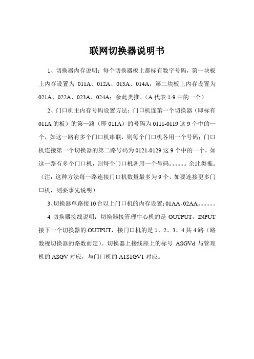
联网切换器说明书
1、切换器内存说明:每个切换器板上都标有数字号码,第一块板上内存设置为011A、012A、013A、014A;第二块板上内存设置为021A、022A、023A、024A;余此类推。
(A代表1-9中的一个)
2、门口机主内存号码设置方法:门口机连第一个切换器(即标有011A的板)的第一路(即011A)的号码为0111-0119这9个中的一个,如这一路有多个门口机串联,则每个门口机各用一个号码;门口机连接第一个切换器的第二路号码为0121-0129这9个中的一个,如这一路有多个门口机,则每个门口机各用一个号码。
余此类推。
(注:这种方法每一路连接门口机数量最多为9个,如要连接更多门口机,则要事先说明)
3、切换器单路接10台以上门口机的内存设置:01AA、02AA。
4切换器接线说明:切换器接管理中心机的是OUTPUT,INPUT 接下一个切换器的OUTPUT,接门口机的是1、2、3、4共4路(路数视切换器的路数而定)。
切换器上接线座上的标号ASGVd与管理机的ASGV对应,与门口机的A1S1GV1对应。
MOD800系列调制解调器说明书V1[1][1][1].41111
![MOD800系列调制解调器说明书V1[1][1][1].41111](https://img.taocdn.com/s3/m/a4631093daef5ef7ba0d3c95.png)
MOD800系列数据转换装置说明书V1.4许继电气二○○九年九月*本说明书可能修改,请注意最新版本目录一、概述 (1)二、主要特点和技术参数 (1)1、主要特点 (1)2、技术参数 (1)三、电路说明 (2)1、模拟通道(MODEM) (2)2、数字通道(DIGIT) (2)四、参数及功能设置 (3)1、模拟通道 (3)2、数字通道 (7)五、原理及机构说明 (8)1、MOD800A(单入单通道输出) (8)2、MOD800B(双入单通道输出) (9)3、MOD800C(单入双通道一数一模拟输出) (11)4、MOD800D(单入双通道输出) (12)5、MOD800E-1(双入双出双通道切换方式—双模) (13)6、MOD800E-2(双入双出双通道切换方式—1数1模) (15)7. MOD800F(双数字通道切换方式) (17)六、注意事项 (19)七、设备选型(输出数字接口默认为RS232,如选用RS422方式须在订货时说明,涉及到MOD800C-1、MOD800C-2、MOD800E-2、MOD800F四种型号) (19)附表1(端子定义图) (20)1、模拟通道口定义 (28)2、数字通道口定义(RS-232) (29)3、数字通道口定义(RS-422) (29)4、电源端口定义 (29)5、串行接口定义(DB9) (29)附表2(S1/S2/S4的设置) (31)MOD800系列数据转换装置一、概述MOD800系列数据转换装置是针对电力系统数据传输的技术特点而设计的,适用于在音频模拟通道或光纤数字通道上传输实时数据。
MOD800系列数据转换装置对数据信号内容不存储、不分析,对传输的数据代码格式没有限制,为客户提供了无记忆效应的“透明”通道。
几年来的现场应用表明,具有传输效率较高、时延较小、功能适用、性能可靠等优点,完全能满足实时通信的要求。
MOD800系列数据转换装置具有模拟通道和数字通道两种接口方式,模拟通道接口是由单片CPU、LSI及其外围元件组成的音频电路。
- 1、下载文档前请自行甄别文档内容的完整性,平台不提供额外的编辑、内容补充、找答案等附加服务。
- 2、"仅部分预览"的文档,不可在线预览部分如存在完整性等问题,可反馈申请退款(可完整预览的文档不适用该条件!)。
- 3、如文档侵犯您的权益,请联系客服反馈,我们会尽快为您处理(人工客服工作时间:9:00-18:30)。
Mod240G通道切换器调试手册
调试步骤如下:
1、准备调试计算机一台(Windows操作系统),RS232串口线一条(串口线为
2、
3针对应2、3针,不交叉,供货时备有专用线)。
2、打开附带的安装光盘。
把MOD240G.exe、Borlndmm.dll、Cc3260mt.dll复制到
调试计算机中,必须在同一文件夹中。
3、将计算机的串口与MOD240G前面板的PC口相连。
4、点击MOD240G.exe,出现如下界面:
5.点击图标(链接设备)。
出现如下结果,表明连接成功,可以设置参数。
如果出现如下结果,表明连接失败,
需做以下检查:
a.MOD240G数据传输终端的电源是否开启。
(如开启可关闭电源再重新开启,等
待10秒后设备复位完成重新连接。
)
b.关闭此程序,重新运行后再次链接。
c.检查RS232串口线连接是否正确,并且检查串口线是否完好(最好使用发货时
的专用串口线,有时用万用表测试没问题,可串口头太短,并不能插紧,导致
链接失败)。
d.检查计算机的串口是否完好,如果没有使用计算机自带的com1,进入“设置串
口”中设置成使用的串口。
6 、链接成功后、根据现场具体要求,给MOD240G装载程序(可以理解成镜像文件)。
在附带的安装光盘中一共有四种功能模式程序,如下:
1.双模拟通道方式程序名称:mod240e1.exe
2.1模拟1数字通道方式程序名称:mod240e2.exe
3.双数字通道方式程序名称:mod240f.exe
4.独立2路模拟通道方式程序名称:mod240a.exe
按自己需求装载程序。
点击“装载程序”,按提示步骤进行即可。
7、装载完程序后,选择菜单栏“设置运行参数”,弹出“设置参数”界面。
左面窗口:
用来设置通道参数。
参数值由用户的调度通信部门来确定,通过下拉框选定即可。
频率与速率绑定设置,预置了自动化远动系统常用的所有速率、频率
的组合方式,特殊的频率可以后续修改软件即可,硬件不做任何修改,发送、接收相位一般为同相,校验位:无。
电平设置:0dBm,也可根据现场情况任意设置。
对于MOD240G我们仅需设置通道1和通道2。
右边窗口:
用来设置切换方式,根据规约以及用户的要求不同来进行设置。
对于我们常用的CDT和IEC101规约,如果为双模拟通道,我们采用MOD240G 的默认方式即可。
默认方式如下:
主机A/B:切换方式;
数据输出A/B:切换输出;
通道1/2:切换方式
切换时间:根据客户要求选择,问答式建议6s到12s,波特率越低,切换时间应该越长;主动上送可以是3s或者6s。
采用这种设置后,MOD240G实现的功能如下:
注:SA、SB代表两台远动机串口;MA、MB代表两个调度的模拟通道
从案例中我们可以看出,程序默认SB口为主,当SB和SA都有数据上送时,仅向通道MA和MB发送SB口数据。
所以建议一般将远动主机连到SB。
