MJSR-51PL003中文资料
低压电机保护器使用说明
适用范围 重要电动机的综合保护 普通电动机的电流保护
SCT选型
SCT型号 SCT5 SCT10 SCT30 SCT100 电动机额定电流 5A及以下 10A及以下 30A及以下 100A及以下 SCT型号 SCT150 SCT200 SCT300 SCT400 电动机额定电流 150A及以下 200A及以下 300A及以下 400A及以下
菜单显示区显示实例(以 HLM-501H 为例)
参数查看显示实例(以 HLM-501H 为例) 地址:安徽省合肥市蜀山区新产业园稻香路 1 号 电话:0551-5357111 (商务)0551-5364943 (技术)
网址: 传真:0551-5364941 邮编:230031
,然后在短路电流数值下有下划光标闪烁。
实例图二 然后可按上移或下移键修改该参数,修改好后按确认键确认修改,修改成功后左下角出现 OK! ,如实例图 三显示。如果放弃修改则按取消键,返回到实例图一显示。
实例图三
HLM-501H/S 系列产品保护功能
短路保护 保护原理
Iset 为短路电流整定值,Tset 为保护延时整定值。 地址:安徽省合肥市蜀山区新产业园稻香路 1 号 电话:0551-5357111 (商务)0551-5364943 (技术) 网址: 传真:0551-5364941 邮编:230031 7
合肥徽力电气技术有限公司
Hefei Huili Electric Tech.Co.,Ltd.
故障类型为 16 进制编码,表示电机运行过程出现故障的原因,通信端口主要用于和显示终端通信以及 软件调试,装置状态显示装置状态和工况,复归按钮用于装置复归。 系统上电 依照说明正确接线后,接通工作电源,显示屏显示与主装置通信建立连接,连接后显示系统图、母线电压、 线路电流、有功功率以及功率因素显示: • 显示母线电压 • 显示电动机运行状态 • 运行指示灯红绿闪烁,表示装置工作中 • 通信灯在有通信时闪烁 • 状态指示灯显示当前电动机的运行状态,红灯为正转运行,绿灯为反转运行,灯熄灭为停车状态
晶体管启动器配件说明书

Length
Packing qty.
Screw head
SRWKITM5X10MM SRWKITM4X15MM SRWKITM5X23MM SRWKITM5X30MM
M5
10mm
M4
15mm
M5
23mm
M5
30mm
20
Pozidrive PZ2
20
Philips
20
Torx T20
20
Torx T20
- Graphite thermal pad for RG series with adhesive on one side
- Width x Height x Thickness = 14 x 35 x 0.13 mm
- Packing qty. 10 pcs.
Ordering Key
RFHT
- Phase change thermal pad for RF1 - Width x Height x Thickness = 19 x 21 x 0.13 mm - Packing qty. 10 pcs.
Suffix H8 added to SSR part no. refers to factory mounted DIN clip. Conditions apply. Please ask your Sales representative for further details.
Ordering Key
Description 250V module with LED 250V module with LED + varistor across output terminals 250V module with pins for easy removal of RP unit 250V module with pins for easy removal of RP unit + LED 600V module with LED
MJSR-51PS003中文资料

Harness Type (H) #26 AWG per MIL-W-16878/4 Type E Teflon, 7/34 stranded.
Length
All Yellow
Color Coded
3 (76.2)
H 020
H 027
6 (152.4)
H 019
H 016
8 (203.2)
H 026
All Yellow H 009 H 010 H 011 H 013 H 017 H 042
Color Coded H 004 H 005 H 006 H 048 H 046 H 041
Solid Uninsulated Type (L) #25 AWG gold plated solid copper.
Stainless steel, passivated & lubricated Stainless steel, passivated Stainless steel, passivated
Post, Polarizing
Stainless steel, passivated
.170 (4.32) MAX.
22
23
34
34 Contacts MJSV (shrouded)
Identification numbers are for reference only and do not appear on connectors.
*Low profile configuration **MJSV & MJSR
元器件交易网
Micro Center Jackscrew
MJS
The MJS jackscrew series provides a reliable interconnect for board-to-board, board-to-cable and in-line cable-to-cable applications. Layouts accommodating up to 76 MICROPIN/MICROSOCKETTM contacts are available, with the same wide range of options as are offered with the other MICRO Line products offered in this catalog.
埃特罗斯电气样本

ፆ 1,0 ੇ 0,9
(Ω) 0,8
0,7
0,6
0,5
0,4
0,3
0,2
0,1
0,0
1
3
5
7
9
ժၿናۅ
图d:阻抗-谐波次数曲线图
11
13
15
17
19
ၿհْຕ
06
非调谐补偿滤波应用场合
如果是工业配电系统,一般5次谐波为频率最低且幅值最大的谐波,对于这 样的配电网,选择非调谐补偿滤波回路的调谐频率次数应低于5次谐波。 右侧图示曲线为电抗率7%的非调谐补偿滤波回路阻抗特性,回路的调谐频 率为189Hz。接入非调谐补偿滤波回路后,可以避免5次及以上谐波的放 大,同时,非调谐补偿滤波回路在调谐频率以上的阻抗低于系统阻抗,回 路可以吸收部分调谐频率以上的谐波,起到滤波作用。
无功补偿和滤波概述
配电网无功补偿与谐波概述
无功功率补偿
在电力系统中,大部分负载在消耗有功功率的同时,也需要大量的无功 功率,这些无功功率并没有被负载真正消耗,而是以电场和磁场的形式 进行交换,因此无功功率将造成: ◎ 占用供电设备容量 ◎ 增加变压器和输电线路损耗 ◎ 降低设备供电电压 ◎ 产生无功罚款,增加用电成本
UA
I UB
ࠃྪۉ
ࠃۉజ၍ UA
Վუഗ r
I
ࢁజ၍
UB
ۉඹഗ
RN XN RT XT
XC
图a:电网简化图及其单线图
串联谐振:图c的曲线图分析了串联起来的变压器和电容器(图b所示)的电路阻抗和谐波次数关系,曲线图显示了发生在11次谐波频率附近的
串联谐振。 当频率接近串联谐振频率时,供电母线上一个相对较低的谐波电压将会引起很大的谐波电流。 较大的谐波电流将会使负载母线上出现较高的谐波电压,使正弦电压发生畸变。
OMRON MOS FET Relay数据手册说明书

1G 3V M 41P R 5I Smallest 40V MOS FET Relay In The Market (USOP Package Size); Designed to exhibit Low Output Capacitance and On Resistance (CxR=10pF·Ω)•Specifically Designed to low ON Resistance 1Ω (typ.)•Dielectric strength of 500Vrms between I/O.■Application Examples■■List of Models*The AC peak and DC value are given for the load voltage.■Absolute Maximum Ratings (Ta = 25°C)Note: The actual product is marked differently from theimage shown here.RoHS CompliantRefer to "Common Precautions ".•Semiconductor test equipment•Test & measurement equipment•Communication equipment •Data loggersNote: The actual product is marked differently from the image shown here.Package type Contact form TerminalsLoad voltage (peak value) *ModelMinimum package quantity Number per tape & reelUSOP41a(SPST-NO)Surface-mounting terminals40VG3VM-41PR5−G3VM-41PR5 (TR05)500ItemSymbol Rating Unit Measurement conditionsI n p u tLED forward currentI F 50mANote:1. The dielectric strength betweenthe input and output was checked by applying voltage between all pins as a group on the LED side and all pins as a group on the light-receiving side.LED forward current reduction rate ∆I F /°C −0.5 mA/°C Ta ≥25°C LED reverse voltage V R 5 V Connection temperature T J 125 °C O u t p u tLoad voltage (AC peak/DC)V OFF 40V Continuous load current (AC peak/DC)I O 300mA ON current reduction rate ∆I O /°C −3mA/°C Ta ≥25°CPulse ON currentlop 900mA t=100ms, Duty=1/10Connection temperature T J 125°C Dielectric strength between I/O (See note 1.)V I-O 500Vrms AC for 1 minAmbient operating temperature Ta −40~+85°CWith no icing or condensation Ambient storage temperature Tstg −40~+125°C With no icing or condensation Soldering temperature−260 °C10s2G3VM-41PR5MOS FET RelaysG 3V M 41P R 5I U S O P ■Recommended Operating ConditionsUse the G3VM under the following conditions so that the Relay will operate properly.■Engineering Data■Safety Precautions•Refer to "Common Precautions " for all G3VM models.ItemSymbol MinimumTypical MaximumUnit Load voltage (AC peak/DC)V DD −−32V Operating LED forward current I F 57.520mA Continuous load current (AC peak/DC)I O −−300mA Ambient operating temperatureTa−20−65°CLED forward current vs.Ambient temperatureContinuous load current vs.Ambient temperatureLED forward current vs.LED forward voltageContinuous load current vs.On-state voltageOn-state resistance vs.Ambient temperatureTrigger LED forward current vs.Ambient temperatureTurn ON, Turn OFF time vs.LED forward currentTurn ON, Turn OFF time vs.Ambient temperatureCurrent leakage vs. Load voltageOutput terminal capacitanceCOFF/COFF(0v) vs. Load voltageI F - TaAmbient temperature Ta (°C)L E D f o r w a r d c u r r en t I F (m A )102030405060-4020-204060801000I O - TaAmbient temperature Ta (°C)C o n t i n u o us l o a d c u r r e n t I O (m A )-40-20204060801000100200300400I F - V FLED forward voltage V F (V)L E D f o r w a r d c u r r e nt I F (m A )0.11101000.81 1.2 1.4 1.6I O - V ONOn-state voltage V ON (V)C o n t i n u o u s l o a d c u r r e n t I O (m A)-0.40.4-0.20.20-400-300-200-1000100200300400R ON - TaAmbient temperature Ta (°C)O n -s t a t e r e s i s t a n c e R O N (Ω)-40-200204060801000123I FT - TaAmbient temperature Ta (°C)T r i g g e r L E D f o r w a r d c u r r e n t I F T (m A )0123-40-2020406080100t ON , t OFF - I FLED forward current I F (mA)T u r n O N , T u r n O F F t i m e t O N , t O F F (µs )101001000110100t ON , t OFF - TaAmbient temperature Ta (°C)T u r n O N , T u r n O F F t i m e t O N , t O F F (µs)101001000-40-2020406080100I LEAK - V OFFLoad voltage V OFF (V)C u r r e n t l e a k a g e I L E A K (p A)10203040051015C OFF - V OFFLoad voltage V OFF (V)O u t p u t t e r m i n a l c a p a c i t a n c e C O F F /C O F F (0v )102030405000.20.40.60.81■Dimensions(Unit: mm)Note: The actual product is marked differently from the image shown here.Actual Mounting Pad Dimensions(Recommended Value, Top View)Note: The actual product is marked differently from the image shown here.Surface-mounting TerminalsWeight: 0.03g• Application examples provided in this document are for reference only. In actual applications, confirm equipment functions and safety before using the product.• Consult your OMRON representative before using the product under conditions which are not described in the manual or applying the product to nuclear control systems, railroad systems, aviation systems, vehicles, combustion systems, medical equipment, amusement machines, safety equipment, and other systems or equipment that may have a serious influence on lives and property if used improperly. Make sure that the ratings and performance characteristics of the product provide a margin of safety for the system or equipment, and be sure to provide the system or equipment with double safety mechanisms.Cat. No. K201-E1-010114(0114)(O)Note: Do not use this document to operate the Unit.OMRON CorporationELECTRONIC AND MECHANICAL COMPONENTS COMPANYContact: /ecb。
液晶电子工业有限公司产品数据手册:液晶电子电机启动器套件、联击器、热过载保护传感器说明书
T h e i n f o r m a t i o n p r o v i d e d i n t h i s d o c u m e n t a t i o n c o n t a i n s g e n e r a l d e s c r i p t i o n s a n d /o r t e c h n i c a l c h a r a c t e r i s t i c s o f t h e p e r f o r m a n c e o f t h e p r o d u c t s c o n t a i n e d h e r e i n .T h i s d o c u m e n t a t i o n i s n o t i n t e n d e d a s a s u b s t i t u t e f o r a n d i s n o t t o b e u s e d f o r d e t e r m i n i n g s u i t a b i l i t y o r r e l i a b i l i t y o f t h e s e p r o d u c t s f o r s p e c i f i c u s e r a p p l i c a t i o n s .I t i s t h e d u t y o f a n y s u c h u s e r o r i n t e g r a t o r t o p e r f o r m t h e a p p r o p r i a t e a n d c o m p l e t e r i s k a n a l y s i s , e v a l u a t i o n a n d t e s t i n g o f t h e p r o d u c t s w i t h r e s p e c t t o t h e r e l e v a n t s p e c i f i c a p p l i c a t i o n o r u s e t h e r e o f .N e i t h e r S c h n e i d e r E l e c t r i c I n d u s t r i e s S A S n o r a n y o f i t s a f f i l i a t e s o r s u b s i d i a r i e s s h a l l b e r e s p o n s i b l e o r l i a b l e f o r m i s u s e o f t h e i n f o r m a t i o n c o n t a i n e d h e r e i n .Product data sheetCharacteristicsLR9D32KITD18BDTESYS motor starter kit, LC1D18BD contactor,LR9D32 thermal overload relayProduct availability: Non-Stock - Not normally stocked in distribution facility MainRange TeSysProduct or componenttypeMotor starterContactor application Motor controlResistive loadUtilisation category AC-4AC-1AC-3Poles description3PPower pole contactcomposition3 NO[Ue] rated operationalvoltagePower circuit <= 690 V AC 25...400 HzPower circuit <= 300 V DC[Ie] rated operationalcurrent18 A 140 °F (60 °C)) <= 440 V AC AC-3 power cir-cuit32 A 140 °F (60 °C)) <= 440 V AC AC-1 power circuit Motor power kW4 KW 220...230 V AC 50/60 Hz AC-3)7.5 KW 380...400 V AC 50/60 Hz AC-3)9 KW 415...440 V AC 50/60 Hz AC-3)10 KW 500 V AC 50/60 Hz AC-3)10 KW 660...690 V AC 50/60 Hz AC-3)4 kW 400 V AC 50/60 Hz AC-4)Motor power HP (UL /CSA)1 Hp 115 V AC 50/60 Hz 1 phase3 Hp 230/240 V AC 50/60 Hz 1 phase5 Hp 200/208 V AC 50/60 Hz 3 phase5 Hp 230/240 V AC 50/60 Hz 3 phase10 Hp 460/480 V AC 50/60 Hz 3 phase15 hp 575/600 V AC 50/60 Hz 3 phaseControl circuit type DC standard[Uc] control circuit volt-age24 V DCAuxiliary contact com-position1 NO + 1 NC[Uimp] rated impulsewithstand voltage6 kV IEC 60947Overvoltage category III[Ith] conventional freeair thermal current10 A 140 °F (60 °C) signalling circuit32 A 140 °F (60 °C) power circuitIrms rated making ca-pacity140 A AC signalling circuit IEC 60947-5-1250 A DC signalling circuit IEC 60947-5-1300 A 440 V power circuit IEC 60947Rated breaking capacity300 A 440 V power circuit IEC 60947[Icw] rated short-timewithstand current145 A 104 °F (40 °C) - 10 s power circuit240 A 104 °F (40 °C) - 1 s power circuit40 A 104 °F (40 °C) - 10 min power circuit84 A 104 °F (40 °C) - 1 min power circuit100 A - 1 s signalling circuit120 A - 500 ms signalling circuit140 A - 100 ms signalling circuitAssociated fuse rating10 A gG signalling circuit IEC 60947-5-150 A gG <= 690 V type 1 power circuit35 A gG <= 690 V type 2 power circuitAverage impedance 2.5 mOhm - Ith 32 A 50 Hz power circuit[Ui] rated insulation volt-agePower circuit 690 V IEC 60947-4-1Power circuit 600 V CSAPower circuit 600 V ULSignalling circuit 690 V IEC 60947-1Signalling circuit 600 V CSASignalling circuit 600 V ULElectrical durability 1.65 Mcycles 18 A AC-3 <= 440 V1 Mcycles 32 A AC-1 <= 440 VPower dissipation perpole2.5 W AC-10.8 W AC-3Safety cover WithMounting support PlateRailStandards CSA C22.2 No 14EN 60947-4-1EN 60947-5-1IEC 60947-4-1IEC 60947-5-1UL 508Product certifications LROS (Lloyds register of shipping)DNVGLRINABVCCCULCSAGOSTConnections - terminals Control circuit screw clamp terminals 1 0.00…0.01 in² (1…4 mm²)flexible without cable endControl circuit screw clamp terminals 2 0.00…0.01 in² (1…4 mm²)flexible without cable endControl circuit screw clamp terminals 1 0.00…0.01 in² (1…4 mm²)flexible with cable endControl circuit screw clamp terminals 2 0.00…0.00 in² (1…2.5 mm²)flexible with cable endControl circuit screw clamp terminals 1 0.00…0.01 in² (1…4 mm²)solid without cable endControl circuit screw clamp terminals 2 0.00…0.01 in² (1…4 mm²)solid without cable endPower circuit screw clamp terminals 1 0.00…0.01 in²(1.5…6 mm²)flexible without cable endPower circuit screw clamp terminals 2 0.00…0.01 in²(1.5…6 mm²)flexible without cable endPower circuit screw clamp terminals 1 0.00…0.01 in²(1…6 mm²)flexible with cable endPower circuit screw clamp terminals 2 0.00…0.01 in²(1…4 mm²)flexible with cable endPower circuit screw clamp terminals 1 0.00…0.01 in²(1.5…6 mm²)solid without cable endPower circuit screw clamp terminals 2 0.00…0.01 in²(1.5…6 mm²)solid without cable endTightening torque Power circuit 15.05 lbf.in (1.7 N.m) screw clamp ter-minals flat Ø 6 mmPower circuit 15.05 lbf.in (1.7 N.m) screw clamp ter-minals Philips No 2Control circuit 15.05 lbf.in (1.7 N.m) screw clampterminals flat Ø 6 mmControl circuit 15.05 lbf.in (1.7 N.m) screw clamp ter-minals Philips No 2Operating time53.55...72.45 ms closing16...24 ms openingSafety reliability level B10d = 1369863 cycles contactor with nominal loadEN/ISO 13849-1B10d = 20000000 cycles contactor with mechanicalload EN/ISO 13849-1Mechanical durability30 McyclesMaximum operating rate3600 cyc/h 140 °F (60 °C)Relay application Motor protectionPhase failure sensitivity Phase difference > 40% 3 s IEC 60947-4-1 ComplementaryCoil technology With integral suppression deviceControl circuit voltage limits Drop-out 0.1...0.25 Uc DC 140 °F (60 °C))Operational 0.7...1.25 Uc DC 140 °F (60 °C))Time constant28 msInrush power in W 5.4 W 68 °F (20 °C))Hold-in power consumption in W 5.4 W 68 °F (20 °C)Auxiliary contacts type Mechanically linked 1 NO + 1 NC IEC 60947-5-1Mirror contact 1 NC IEC 60947-4-1Signalling circuit frequency25...400 HzMinimum switching current5 mA signalling circuitMinimum switching voltage17 V signalling circuitNon-overlap time 1.5 Ms on de-energisation between NC and NO contact1.5 ms on energisation between NC and NO contactInsulation resistance> 10 MOhm signalling circuitContact compatibility M4Motor power range4…6 KW 200…240 V 3 phase7…11 KW 380…440 V 3 phase7…11 kW 480…500 V 3 phaseMotor starter type Direct on-line contactorContactor coil voltage24 V DC standardThermal overload class Class 5 (30)Thermal protection adjustment range 6.4…32 AMaximum power consumption in W300 mWMounting support Under contactorPlate, with specific accessoriesRail, with specific accessories[Ue] rated operational voltage690 V power circuit660 V signalling circuit[Ui] rated insulation voltage Power circuit 1000 VSignalling circuit 690 VTripping threshold 1.25 In IEC 60947-4-1Control type Red push-button stop and manual resetWhite 2 microswitches adjustable trip classRed knob automatic resetGrey dial full-load current adjustmentTime range 1.5...4 min - automatic reset time[Ith] conventional free air thermal current5 A signalling circuitAssociated fuse rating5 A gG signalling circuit5 A BS signalling circuit[Uimp] rated impulse withstand voltage6 kVIP degree of protection Front face IP20 IEC 60529Front face IP20 VDE 0106Mechanical robustness Vibrations 10...150 Hz 6 Gn) IEC 60068-2-6Shocks 11 ms 15 gn) IEC 60068-2-7Connections - terminals Control circuit screw clamp terminals 1 0.00 in² (2.5 mm²) solid or flexible - with-out cable endPower circuit screw clamp terminals 1 0.02 in² (16 mm²) solid or flexible - withoutcable endTightening torque Control circuit 0.8 N.m screw clamp terminalsPower circuit 3.1 N.m screw clamp terminalsEnvironmentIP degree of protection IP20 front face IEC 60529Protective treatment TH IEC 60068-2-30Pollution degree3Ambient air temperature for operation23…140 °F (-5…60 °C)-40…158 °F (-40…70 °C) at UcPermissible ambient air temperature around the de-viceOperating altitude9842.52 ft (3000 m) withoutMechanical robustness Vibrations contactor open2 Gn, 5...300 HzVibrations contactor closed4 Gn, 5...300 HzShocks contactor open10 Gn for 11 msShocks contactor closed15 Gn for 11 msHeight 3.03 in (77 mm)Width 1.77 in (45 mm)Depth 3.74 in (95 mm)Net weight 1.08 lb(US) (0.49 kg)Standards UL 60947-4-1IEC 60947-4-1CSA C22.2GB 14048.4Product certifications CSACCCTÜVCULusAmbient air temperature for operation-13…158 °F (-25…70 °C) IEC 60255-8Ambient air temperature for storage-76…176 °F (-60…80 °C)Ambient air temperature for storage-67…176 °F (-55…80 °C)Operating altitude6561.68 ft (2000 m) without deratingFire resistance1562 °F (850 °C) IEC 60695-2-1Flame retardance V1 UL 94Electromagnetic compatibility Surge withstand 2 kV common mode IEC 61000-4-5Resistance to electrostatic discharge 8 kV IEC 61000-4-2Immunity to radiated radio-electrical interference 10 V/m IEC 61000-4-3Immunity to fast transients 2 kV IEC 61000-4-4Dielectric strength6 kV 50 Hz IEC 60255-5Height 2.85 in (72.5 mm)Width 1.77 in (45 mm)Depth 3.15 in (79.9 mm)Net weight0.40 lb(US) (0.18 kg)Ordering and shipping detailsCategory22350 - LR9D AND TESYS D STARTER KITSDiscount Schedule I12Package weight(Lbs)0.80 kg (1.76 lb(US))Returnability YesCountry of origin CNOffer SustainabilityEU RoHS Directive Under investigation。
电路保护用正温度系数(PTC)热敏电阻
b
电流 (对数)
c
E
RL
a
I
A
I
=
E - Vp RL
B
电压 (对数)
E
[保护门限电流范围]
1000
电流 (mA)
800 跳闸电流
600 保护门限电流
400 不工作电流
200
0 -20
0 20 40 60 周围温度 (℃)
[工作电流]
I0
I0 2
电流 (A)
R90C.pdf 05.07.22
目录
1
本产品目录中的POSISTORr 与“POSISTOR”是村田制作所的注册商标。
品名表示法 POSISTORr 的基本特性 选择指南 用途一览表 1 过载电流保护用 片状型
片状型规格与测试方法
2 过载电流保护用 窄电流偏差 30V系列 3 过载电流保护用 窄电流偏差 51/60V系列 4 过载电流保护用 窄电流偏差 140V系列 5 过载电流保护用 24/30/32V系列 6 过载电流保护用 56/80V系列 7 过载电流保护用 125/140V系列 8 过载电流保护用 250/265V系列 PTGL系列窄电流偏差规格与测试方法 PTGL系列规格与测试方法 9 过热传感用 片状型 片状型 (仅供参考) 片状窄偏差型 (仅供参考) 片状型规格与测试方法 片状窄偏差型规格与测试方法 10 过热传感用 引线型
例如)
代码 470 471
电阻值 47Ω 470Ω
y电阻值允许偏差 代号 M Q
电阻值允许偏差 ±20%
特定允许偏差
u特殊规格 代号 B1
特殊规格 结构和其他
i包装 代号 RA RB RK
江阴斯菲尔电能质量样本
SFR-MXD-2010-P7/480 SFR-MXD-30-P7/280
20
第七部分
7.1 7.2
21
7.3 7.4
22
7.5
23
第八部分
8.1 8.2
8.2.1
24
8.2.2
25
8.3
26
8.4 8.5
27
第九部分
9.1 9.2 9.3
28
9.5
29
9.6
30A~50A: 442×188×647 75A~120A: 600×600×2200 150A~240A: 800×800×2200 300A~400A: 1200×1000×2200
30
第十部分
10.1 通用型 (主要与LBK、LBKT、LBG等系列产品配套使用)
■ 型号说明
产品代号:无功功率补偿控制器
■ 主要功能
1、参数设置功能 过压值、欠压值、过温度值等保护定值的设置; 延时时间、投入、切除门限等投切限值的设置; 取样电流互感器变比的设置。
2、测量功能 取样互感器极性自动判别,接入时无需考虑极性要求; 配电电压、电流、功率因数、有功功率、无功功率测量;
3、控制功能 自动、手动控制电容器的投切。自动控制时,根据受控物理量(无
5、信号功能 各台电容器投运、退运信号显示,各台电容器容量信号显示; 配电参数越限信号(过压、欠压等)显示; 控制器本身或电容器故障显示;
34
■ 主要技术参数
项目 量程
电 过载
信压 功耗
号 量程
输电 过载
入流 功耗
频率 电源
通讯
报警输出
测量等级
3RW51 软起动器
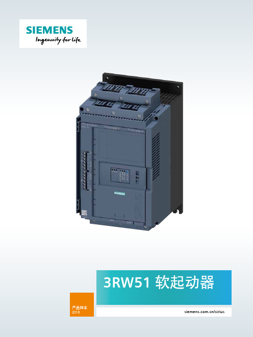
5873产品概述3RW51软起动器是西门子在对市场软起应用深刻了解的基础上研发推出的一款全新的国产软起动器产品。
可广泛应用于风机、泵、传送带、压缩机等需要对起动,停车进行控制的负载。
三相控制额定工作电压:200 ~ 480 VAC , -15% ~ 10%额定控制电源电压:110 ~ 250 V ,50/60 Hz ,-15% ~ 10%额定工作电流:13 ~ 987 A 外置旁路接触器标准接线及内三角接线带防护涂层控制板,可有效抵御灰尘、潮湿和腐蚀性气体可选的标准操作面板或高性能操作面板支持多种主流通讯协议具有模拟量输出,4 ~ 20mA ,0 ~ 10V 信号可选软转矩及泵停止功能软起动器的应用及选型帮助软起动器通过限制起动电流和起动转矩,能够可靠地防止起动过程中的机械冲击和电网压降。
通过对可控硅导通角的控制,来降低电机起动电压,并在设定的起动时间内,将电机起动电压升高到额定电压。
凭借这种电机电压的无阶跃控制,可以根据被驱机器的负载特性对电机进行调节,平缓加速机械设备,从而显著提高机械设备的运行性能,减少维护成本,延长使用寿命。
软起动器广泛应用于市政、冶金、石化、矿山、建筑、汽车、纺织、造纸等领域。
常用负载如下:水泵 — 有效改善水锤效应,保护管道、密封、阀门等机械部件风机 — 减少机械磨损及对电网的冲击,节约维修成本压缩机 — 实现平滑起动,延长电机使用寿命皮带运输机 — 减少机械冲击对皮带的损伤,避免运输物料的位移,保护运输对象等等。
•充分了解负载的特性及使用情况•软起动器的规格应始终大于电机的电流值(额定工作电流)。
对于出现偏离额定值的情况,应必须选择规格较大的软起动器。
•安装海拔高度:最高 5000 m ,1000 m 以上需考虑降容,具体降容系数见产品样本。
产品选型标准应用 CLASS10E重载CLASS20E以上选型仅供参考,如需更精确的选型,请使用软起动器模拟仿真选型工具选型https:///cs/document/101494917/simulation-tool-for-soft-starters-(sts)-v3-0-upd-1?dti=0&lc=de-WW重载CLASS20E产品选型标准应用 CLASS10E以上选型仅供参考,如需更精确的选型,请使用软起动器模拟仿真选型工具选型https:///cs/document/101494917/simulation-tool-for-soft-starters-(sts)-v3-0-upd-1?dti=0&lc=de-WW70 75通用数据符合标准:EN/IEC60947-4-2。
注塑机相关技术参数
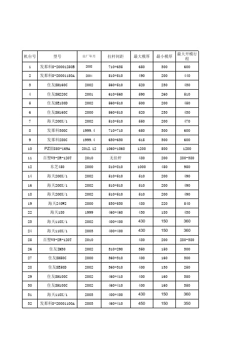
海天110X/1 东芝EC100S-2A 东芝EC100S-2A 住友SH130C 住友SH130C 住友SH130D 住友SH130D 发那科S-2000i150A 发那科S-2000i150A 发那科S-2000i150A 发那科S-2000i150A 东芝IS55OGS 东芝EC350C 东芝EC220C 住友SE180S 发那科S-2000i150A 发那科S-2000i150A 发那科S-2000i150A 发那科S-2000i150A 发那科S-2000i150A
430 550 550 430 430 450 450 490 490 490 490 1000 650
150 180 180 180 180 250 250 200 200 200 200 400
360 350 350 375 375 375 375 440 440 440 440 1200
2007.6 2007.1 2002 2002 2002 2002 2002 2005 2002 2002 2002 2002 2011 2011 2011 2011 2011
高速机
STAR 有信单臂 天行 天行
130823积康 110826 081207 101104 没更换过 080407 081205 110226 101222 新机 没更换过 110331 140116 110428 090924 100906 120204积康 120607腾明 120209北仑 131123红建
600*550 510*510 510*510 510*510 510*510 510*510 510*510 600*460 510*510 510*510 510*510 510*510 410*410 410*410 360*360 360*360 470*470
夏普M160M205零件手册中文_部分2

O第二纸盒给纸组件 (AR-M205)O第二纸盒给纸组件AR-RP6 MODEL目 录为确保安全性、可靠性,更换部品务必使用正规品。
指定的部品。
本手册仅供维修人员进行售后服务用,本手册内容如有更改,恕不通告。
SHARP CORPORATION部 品 手 册1234■外观给纸组件输送组件包装及附属品索引数码复合机选购件双面原稿输送器(RSPF)1外观1外观3输送组件3输送组件4包装及附属品4包装及附属品AR-D24单层纸盒AR-D25双层纸盒MODEL目 录为确保安全性、可靠性,更换部品务必使用正规品。
指定的部品。
本手册仅供维修人员进行售后服务用,本手册内容如有更改,恕不通告。
SHARP CORPORATION部 品 手 册123456■单层纸盒外观 (AR-D24)单层纸盒给纸组件 (AR-D24)双层纸盒外观 (AR-D25)双层纸盒给纸组件 (AR-D25)250页纸盒组件包装材料及附属品索引数码复合机选购件进纸组件1单层纸盒外观 (AR-D24)1单层纸盒外观 (AR-D24)2单层纸盒给纸组件 (AR-D24)2单层纸盒给纸组件 (AR-D24)4双层纸盒给纸组件 (AR-D25)4双层纸盒给纸组件 (AR-D25)5250页纸盒组件5250页纸盒组件6包装材料及附属品6包装材料及附属品■索引– 12 –COPYRIGHT © 2003 BY SHARP CORPORATION版权所有 翻印必究夏普办公设备(常熟)有限公司上海经营部中国上海浦东新金桥路28号新金桥大厦1601室 2003年10月中国印刷。
501 Valves 三方自动球式转值, Series 3PBV 型号 Plastic Pneuma
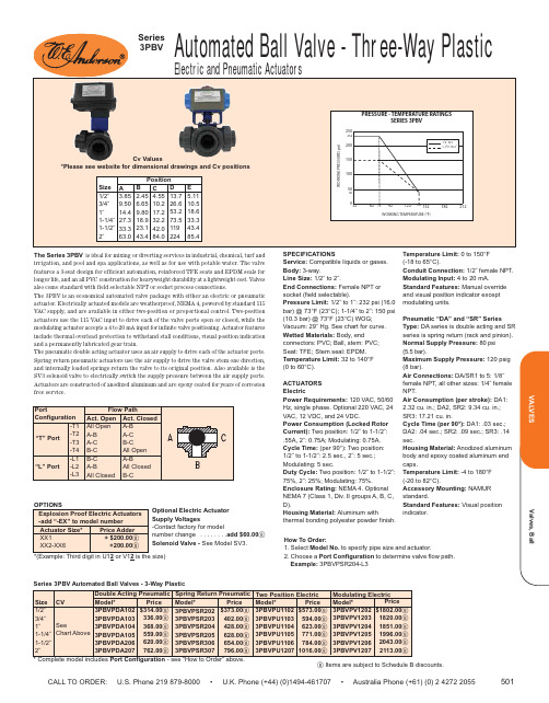
CALL TO ORDER: U.S. Phone 219 879-8000 • U.K. Phone (+44) (0)1494-461707 • Australia Phone (+61) (0) 2 4272 2055501The Series 3PBV is ideal for mixing or diverting services in industrial, chemical, turf and irrigation, and pool and spa applications, as well as for use with potable water. The valve features a 3-seat design for efficient automation, reinforced TFE seats and EPDM seals for longer life, and an all PVC construction for heavyweight durability at a lightweight cost. Valves also come standard with field selectable NPT or socket process connections.The 3PBV is an economical automated valve package with either an electric or pneumatic actuator. Electrically actuated models are weatherproof, NEMA 4, powered by standard 115VAC supply, and are available in either two-position or proportional control. Two-position actuators use the 115 VAC input to drive each of the valve ports open or closed, while the modulating actuator accepts a 4 to 20 mA input for infinite valve positioning. Actuator features include thermal overload protection to withstand stall conditions, visual position indication and a permanently lubricated gear train.The pneumatic double acting actuator uses an air supply to drive each of the actuator ports.Spring return pneumatic actuators use the air supply to drive the valve stem one direction,and internally loaded springs return the valve to its original position. Also available is the SV3 solenoid valve to electrically switch the supply pressure between the air supply ports.Actuators are constructed of anodized aluminum and are epoxy coated for years of corrosion free service.SPECIFICATIONSService:Compatible liquids or gases.Body:3-way.Line Size:1/2˝ to 2˝.End Connections:Female NPT or socket (field selectable).Pressure Limit:1/2˝ to 1˝: 232 psi (16.0bar) @ 73°F (23°C); 1-1/4˝ to 2˝: 150 psi (10.3 bar) @ 73°F (23°C) WOG;Vacuum: 29˝ Hg. See chart for curve.Wetted Materials:Body, endconnectors: PVC; Ball, stem: PVC; Seat: TFE;Stem seal: EPDM.Temperature Limit:32 to 140°F (0 to 60°C).ACTUATORS ElectricPower Requirements: 120 VAC, 50/60Hz, single phase. Optional 220 VAC, 24VAC, 12 VDC, and 24 VDC.Power Consumption (Locked Rotor Current):Two position: 1/2˝ to 1-1/2˝:.55A, 2˝: 0.75A; Modulating: 0.75A.Cycle Time:(per 90°): Two position:1/2˝ to 1-1/2˝: 2.5 sec., 2˝: 5 sec.;Modulating: 5 sec.Duty Cycle:Two position: 1/2˝ to 1-1/2˝:75%, 2˝: 25%; Modulating: 75%.Enclosure Rating:NEMA 4. Optional NEMA 7 (Class 1, Div. II groups A, B, C,D).Housing Material: Aluminum withthermal bonding polyester powder finish.Temperature Limit:0 to 150°F (-18 to 65°C).Conduit Connection:1/2˝ female NPT.Modulating Input:4 to 20 mA.Standard Features:Manual override and visual position indicator except modulating units.Pneumatic “DA” and “SR” SeriesType: DA series is double acting and SR series is spring return (rack and pinion).Normal Supply Pressure:80 psi (5.5 bar).Maximum Supply Pressure:120 psig (8 bar).Air Connections:DA/SR1 to 5: 1/8˝female NPT, all other sizes: 1/4˝ female NPT.Air Consumption (per stroke):DA1:2.32 cu. in.; DA2, SR2: 9.34 cu. in.;SR3: 17.21 cu. in.Cycle Time (per 90°):DA1: .03 sec.;DA2: .04 sec.; SR2: .09 sec.; SR3: .14sec.Housing Material:Anodized aluminum body and epoxy coated aluminum end caps.Temperature Limit:-4 to 180°F (-20 to 82°C).Accessory Mounting: NAMUR standard.Standard Features:Visual position indicator.How To Order:1. Select Model No.to specify pipe size and actuator.2. Choose a Port Configuration to determine valve flow path.Example:3PBVPSR204-L3*Please see website for dimensional drawings and Cv positions*(Example: Third digit in U12or V12b Items are subject to Schedule B discounts.Optional Electric ActuatorSupply Voltages-Contact factory for modelnumber change . . . . . . . .add $60.00b Solenoid Valve -See Model SV3.。
美国电解放PDF34K0250E3XN电解放纤维筋电容电流保护器说明说明书
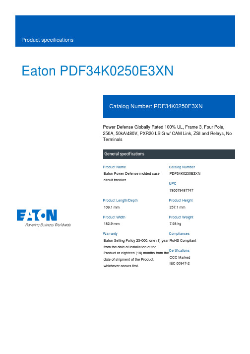
Eaton PDF34K0250E3XNPower Defense Globally Rated 100% UL, Frame 3, Four Pole, 250A, 50kA/480V, PXR20 LSIG w/ CAM Link, ZSI and Relays, No TerminalsEaton Power Defense molded case circuit breakerPDF34K0250E3XN 786679487747109.1 mm 257.1 mm 182.9 mm 7.68 kg Eaton Selling Policy 25-000, one (1) year from the date of installation of theProduct or eighteen (18) months from thedate of shipment of the Product,whichever occurs first.RoHS Compliant CCC MarkedIEC 60947-2Product NameCatalog Number UPCProduct Length/Depth Product Height Product Width Product Weight WarrantyCompliancesCertifications250 AComplete breaker 3Four-pole (100% N)PD3 Global (100% UL) Class APXR 20 LSIGCAM Link600 Vac600 V100% neutral protectionNo Terminals50 kAIC at 480 Vac10 kAIC Icu/ 5 kAIC Ics/ 21 kAIC Icm @690V (IEC)50 kAIC @480V (UL)85 kAIC Icu/ 85 kAIC Ics/ 187 kAIC Icm @240V (IEC)85 kAIC @240V (UL)35 kAIC Icu/ 35 kAIC Ics/ 73.5 kAIC Icm @440V (IEC)25 kAIC @600V (UL/CSA)35 kAIC Icu/ 22.5 kAIC Ics/ 73.5 kAIC Icm @480V Brazil (IEC) 10 kAIC Icu @250 Vdc25 kAIC Icu/ 10 kAIC Ics/ 52.5 kAIC Icm @525V South Africa (IEC)50 kAIC Icu/ 50 kAIC Ics/ 105 kAIC Icm @380-415V (IEC)Eaton Power Defense MCCB PDF34K0250E3XN 3D drawingConsulting application guide - molded case circuit breakers Power Xpert Protection Manager x32Power Xpert Protection Manager x64StrandAble terminals product aidPower Defense brochurePower Defense molded case circuit breaker selection poster Power Defense technical selling bookletMolded case circuit breakers catalogAmperage RatingCircuit breaker frame type FrameNumber of poles Circuit breaker type ClassTrip Type CommunicationVoltage ratingVoltage rating - maxProtectionTerminalsInterrupt rating Interrupt rating rangeTrip rating 3D CAD drawing package Application notesBrochuresCatalogs250 A Power Xpert Release trip units for Power Defense molded case circuitbreakersCertification reportsPDG3 UL authorization 250-600a TMTUPDG3 UL authorization 100-400aInstallation instructionsPower Defense Frame 3 Breaker Instructions (IL012107EN).pdfMultimediaPower Defense Frame 5 Trip Unit How-To VideoPower Defense Frame 2 Variable Depth Rotary Handle MechanismInstallation How-To VideoPower Defense molded case circuit breakersPower Defense Frame 3 Variable Depth Rotary Handle MechanismInstallation How-To VideoEaton Power Defense for superior arc flash safetyPower Defense BreakersPower Defense Frame 6 Trip Unit How-To VideoSpecifications and datasheetsEaton Specification Sheet - PDF34K0250E3XNTime/current curvesPower Defense time current curve Frame 3 - PD3White papersImplementation of arc flash mitigating solutions at industrial manufacturingfacilitiesMaking a better machineIntelligent circuit protection yields space savingsMolded case and low-voltage power circuit breaker healthIntelligent power starts with accurate, actionable dataMolded case and low-voltage breaker healthSafer by design: arc energy reduction techniquesEaton Corporation plc Eaton House30 Pembroke Road Dublin 4, Ireland © 2023 Eaton. All Rights Reserved. Eaton is a registered trademark.All other trademarks areproperty of their respectiveowners./socialmedia。
Uni-ram 重复利用沙砂喷洒器 UR007 系列用户手册说明书

USER MANUAL RECLAIMING SAND BLASTERSMODELSUR007 UR007-YEXPUR007-YJUNI-RAM CORPORATION • ONTARIO • CANADARevised 2010-03CONTENTSINTRODUCTION (3)CAUTIONS AND WARNINGS (3)PREPARATION (4)NOTES ON USE AND OPERATION (4)MAINTENANCE (5)TROUBLESHOOTING (5)FEATURES AND SPECIFICATIONS (5)REPLACEMENT PARTS (6)WARRANTY (7)INTRODUCTIONUni-ram holds many patents on designs used in its innovative products. Every machine is rigorously tested for compliance with stringent Quality Assurance standards. Follow the notes on preparation, use and operation to operate this machine safely and effectively. Ensure that this manual is readily available to the operator at all times. If you have any questions about the operation of this machine, contact:North America:Uni-ram Technical Service1-800-417- 9133Other Continents:Contact Your SupplierCAUTIONS AND WARNINGS• Wear safety glasses and follow all local safety regulations.• Do not leave the unit unattended when plugged in. Unplug from outlet when not in use and before servicing.• To reduce the risk of electric shock, do not use outdoors or near water or wet surfaces.• Do not use with a damaged Power Cord or Plug. If the unit is not working as it should or if it has been dropped, damaged, left outdoors or emersed into water, contact Uni-ram for service instructions.• Keep the Power Cord away from heat.• Do not use without a fi lter.• Turn off the Power Switch before unplugging.• Use only a properly installed, grounded outlet.• The fi lter is water resistant and washable in water. Do not use high pressure air or solvents to clean it.Cleaning with a soft brush is recommended.PREPARATIONNote: Item numbers given below refer to the parts listing on page 6.1. Check for transportation or handling damage.2. Lay the carton on its side and wheel the unit out. Do not stand it back up until Step 9.2. Make sure all parts and accessories are included.3. Remove all packing material.4. Remove the Vacuum Head Assembly and the Debris Container.5. Remove the two items stored underneath the Debris Container during shipping: Tubular Handle,Gun+Head Assembly.6. Install the Tubular Handle with the nuts and screws provided (see picture on Page 6).7. Remove the Hose Assembly from the bag and insert the Abrasive Hose (the smaller of the twohoses), which protrudes past the Vacuum Hose, through the hole at the back of the unit. Connect it to the air outlet underneath the base of the unit.8. Connect the Vacuum Hose to the connecting outlet on the container. Stand the unit back up.9. Pour 20-40 LB (11-18 kg) of abrasive through the strainer at the bottom into the Abrasive Containerunderneath. It is not necessary to remove the strainer.10. Connect the Vacuum Hose and Abrasive Hose to the Blast Head and the Air Line to the Blast Gun.Use the white clamp provided for the Abrasive Hose.11. Re-insert the Debris Container.12. Re-install the Vacuum Head and clamp in position.13. When ready to operate, connect the Power Cord and turn on the Power Switch.NOTES ON USE AND OPERATION1. Use Air Pressure between 75 and 100 PSI depending on the surface to be cleaned.2. Air Volume should be between 8 to 22 CFM (optimum: 16-20 CFM).3. Use one hand to hold the Blast Gun and the other to hold the Blast Head as shown below.4. Do not press downwards - the brush’s function is to reduce the escape of abrasive and to maintain avacuum for the effi cient recycling of the abrasive.5. Move both hands in the same direction.6. The blast area may be varied by lengthening or shortening the nozzle with the Lock Bolt (Item 30,Page 6).7. Careful placement of the brush over the area to be cleaned is very important. The bristlesshould be spread out so that the abrasive spray inside does not impact the bristles. This precaution will preserve the bristles, improve the vacuum effect, create better coverage and utimately result in better savings, safety and results.8. The fl at 1-1/4” brush (Part No. 27-611) is supplied with the unit. Four additional specialty brushes areavailable. The same precautions should be followed when using these brushes.9. When working on a 90° corner, alin the gun at a 45° angle to reach the deepest area. Move the gun ina slow rotating motion for the best results.FILTER PART NO.27-180 STANDARD27-172 HEPAMAINTENANCE1. After each use, knock the dust off the fi lter and after one hour of continuous use, lift off the VacuumHead and check for dust accumulation. Clean the fi lter with a soft brush, vacuum or low-pressure air.MODELUR007UR007-YEXP UR007-YJ POWER (V/W)120/1350240/1350200/1350STANDARD HOSE8.5 FT (2.5m)8.5 FT (2.5m)8.5 FT (2.5m)FILTRATIONCARTRIDGE CARTRIDGE CARTRIDGE SHIP WEIGHT (LB/KG)69/3169/3169/31SHIP SIZE (WDH)20X18X45”20X18X45”20X18X45”FEATURES AND SPECIFICATIONSUni-ram Reclaiming Sand Blasters allow sandblasting without personal breathing apparatus, face masks or separate dust removal. The abrasive media are recovered and re-used continuously for a 92% reduction in media consumption.• Can be used with most abrasives including:• Air fl ow: 8-22 CFM glass beads, metal shot, aluminum oxide,• Air pressure: variable to 150 PSI nut shells, plastic pearls, baking soda etc.• Fume grade fi lter standard, HEPA available • Uses standard air fi ttings • Motor Speed: 19,600 RPM SYMPTOMCAUSE AND REMEDY Decrease in blast performance Low air presure. Check compressor and hose connections forleaks. Check CFM and PSI input.Moisture in the abrasive.The air supply must be clean and dry.Abrasive is worn or too fi ne and does not cut the surface.Vacuum Filter needs cleaning; debris collects with the media.Gun blockage. Disconnect air and power, unscrew nozzle, use apaper clip or thin wire to clear the passageway.Decrease in vacuum performance Filter needs cleaning.Check vacuum lines for blockage or leakage.Check CFM input.Abrasive escapes from betweenbristles of brush Air pressure is too high.Check vacuum lines for blockage or leakage.TROUBLESHOOTINGREPLACEMENT PARTSGUN + HEAD ASSEMBLY 27-500OPTIONAL BRUSHES ITEMPART NO.DESCRIPTION 1Z9852Moulding, Head Cover 220-101-Y Head Cover 327-100S Vac Head Assy, Complete, 120V 4110-313Pull Handle 527-129*Motor Brush 6KIT-26123*Vac Motor Kit, 1350W, 120V 6.1KIT-26127*Vac Motor Kit, 1350W, 240V 6.2KIT-26125*Vac Motor Kit, 1350W, 100V 6a27-151Valve Stem Assy for U5047727-103Gasket Motor Mount 827-131Power Switch 120V 8.127-132Power Switch 240V 927-141Neon Lamp 100-120V 9.127-142Neon Lamp 220V 1027-112Thermal Separator Plate 1127-193Vacuum Head Seal Gasket 1227-218Rim Clamp 1327-180Filter, Regular 13.127-172HEPA Filter 1425-215Debris Container 1527-217Tubular Handle 1627-710Vacuum Hose Assy (8 )16.127-712Vacuum Hose Assy (10 FT)16+1827-700Complete Hose Assembly, 8’1727-721Hose End Cuff, 1.5”1827-731Abrasive Feeder Hose (8 FT)18.127-732Abrasive Feeder Hose (10 FT)1927-231Abrasive Screen 20Z123Abrasive Screen Knob 2111-161Wheel, 6” Heavy Duty Industrial 2227-381Axle Shaft 1/2” x 18” ZP 2327-384Wheel Cap, High Impact, 1/2” Axle 2427-378Swivel Caster, 2” Wheel 2520-250Impeller Assembly 2620-210-Y Body Tube Assembly 27U5047Blast Gun Assembly 27+3127-500Blast Gun+Head (U5047+27-570)2851-252Air Jet, 1/8” ID for Blast Guns 2952-055Steel Blast Nozzle 29.152-020Ceramic Blast Nozzle 29.252-010Carbide Blast Nozzle 3027-513Lock Bolt, 1/4” x 1/2”ITEM PART NO.DESCRIPTION 3127-570Blast Head incl. Brush (27-611)3227-571Blast Head without Brush 3327-512O Ring, D3303427-611Flat Brush 1-1/4”, Standard 34.127-612Flat Brush 1-3/4”, Optional 3627-621Inside Corner Brush (90º Male)3727-631Outside Corner Brush (90º Female)3827-650Brush and Holder (for thin edges)27-914Abrasive, #60, 25 LB Pail 51-270Valve Stem Assy for U5047* For units purchased before 2005-12, call before orderingFull Product WarrantyThese Uni-ram products have been engineered and manufactured to high performance standards. Each unit has been subjected to detailed factory testing before shipment.This product comes with a one-year full warranty from the date of purchase. Uni-ram Corporation reserves the right to repair or replace the unit, free of charge, to the original purchaser if a part is found to be defective in material or workmanship as determinedby factory service personnel. The items listed below under “Conditions of Warranty” as consumables are not covered.Uni-ram reserves the right to direct the customer to ship the unit collect to the Uni-ram factory or to an approved Service Center for repair using the Uni-ram Return Goods Procedure or to repair the unit on-site. To prevent damage in transport, the purchaser must ship the unit in the original packaging or use alternate adequate packaging. All units must be shipped clean and free of solvent.Conditions of Warranty:As Uni-ram Corporation has no control over the working conditions or circumstances under which the purchaser stores, handles or uses the product, Uni-ram makes no war-ranty or claim, either expressed or implied with respect to this product’s fi tness for any purpose or the result to be obtained from its use. This condition applies to the sale of all products and no representative or distributor of Uni-ram Corporation has the authority to waive or change these conditions.This warranty applies only to the original purchaser and does not apply if the unit has been misused, overloaded, neglected, altered or used for any purpose other than those specifi ed in the operating and installation instructions. Deterioration due to normal wear is not covered by this warranty. Damage due to accident, transportation, fi re, fl oodsor acts of God is also not covered. Units whose serial numbers have been altered or removed are not covered. The warranty is invalid if unauthorized abrasives are used in this unit. Unauthorized attempts at self-repair or alterations by the owner also invalidate this warranty. Interior or exterior fi nishes are not covered by this warranty.Consumable Items are not covered by this warranty.This warranty replaces all other warranties expressed or implied by statute or otherwise.To make a claim, call Uni-ram Service at 1-800-417-9133 and quote the serial number of the unit.。
Miller Revolution Premium R5 三点电信、电力和电缆护目具系列说明说明书
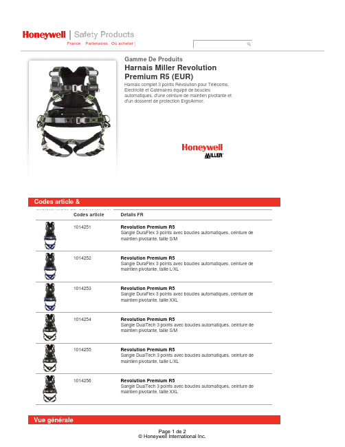
France PartenairesOù acheterCodes articleDetails FR 1014251Revolution Premium R5Sangle DuraFlex 3 points avec boucles automatiques, ceinture demaintien pivotante, taille S/M1014252Revolution Premium R5Sangle DuraFlex 3 points avec boucles automatiques, ceinture demaintien pivotante, taille L/XL1014253Revolution Premium R5Sangle DuraFlex 3 points avec boucles automatiques, ceinture demaintien pivotante, taille XXL1014254Revolution Premium R5Sangle DualTech 3 points avec boucles automatiques, ceinture demaintien pivotante, taille S/M1014255Revolution Premium R5Sangle DualTech 3 points avec boucles automatiques, ceinture demaintien pivotante, taille L/XL1014256Revolution Premium R5Sangle DualTech 3 points avec boucles automatiques, ceinture demaintien pivotante, taille XXLCodes article &Informations de commande Vue généraleHarnais Miller RevolutionPremium R5 (EUR)Gamme De ProduitsHarnais complet 3 points Révolution pour Télécoms,Electricité et Caténaires équipé de bouclesautomatiques, d'une ceinture de maintien pivotante etd'un dosseret de protection ErgoArmor.Harnais Miller Revolution Premium R5 (EUR)Caractéristiques principalesQuand l'innovation et le design révolutionnent le harnais antichute.Harnais complet 3 points à utiliser avec un dispositif d'antichute et un point d'amarrage adapté. La solution parfaite pour les Télécoms, l'intervention sur Eolienne, l'électricité et les caténaires. Les axes pivotants PivotLink se situent au niveau des hanches pour une plus grande liberté de mouvement de l'utilisateur, surtout lorsque ce dernier accède à desstructures nécessitant de monter ou descendre. La ceinture de maintien pivotante permet à l'utilisateur de se déplacer latéralement ou vers l'arrière sans aucune gêne. Une gamme de nombreux accessoires est disponible, à clipperdirectement sur le Pivot Link.Harnais disponible en 2 versions de sangle :Sangles DualTech : facile à mettre grâce à sa sangle double face distincte de chaque côté par ses couleurs et ses textures très contrastées. Conçue avec une mémoire de forme pour un meilleur ajustement sur l'utilisateur.Sangles DuraFlex : Les sangles extensibles et brevetées en élastomère s'adaptent à la morphologie de l'utilisateur, le laissant complètement libre de ses mouvements.Secteurs d'activité recommandésEnergieRisquesChute de hauteurRéglementationsConformes à la norme EN 361 et EN 358.Informations de garantieNos équipements de pointe fournissent aux ouvriers des outils indispensables pour assurer une protection optimale, en associant la mobilité et un confort exceptionnel.Nos sites de production européens sont certifiés ISO 9001. Chaque produit Miller ® by Sperian est réalisé conformément aux normes en vigueur afin de répondre aux demandes des clients les plus exigeants.Miller Revolution Instruction manual - 90014448 (EUR)/Supplementary/Documents_and_Downloads/Fall_Protection/Full_Body_Harness/40873/1033.aspxNotice90004212 harness EN 361, 358 (EUR)/Supplementary/Documents_and_Downloads/Fall_Protection/Full_Body_Harness/41640/1033.aspxNoticeLa formation est une partie essentielle de tout programme de sécurité. L’employeur est chargé de s’assurer que toute personne travaillant en hauteur est totalement formée à l’utilisation correcte des systèmes et des équipements deprotection individuelle.En savoir plus sur les formations…Miller TechniservPhone: +33 (0)2 48 52 40 42Email:****************************© Honeywell International Inc.。
Dwyer Instruments SERIES WE05 三段铝合金球控值说明书

APPLICATIONSDESCRIPTIONThe SERIES WE05 offers the best possible design for socket weld ball valves. The swing out body feature and seat arrangement allow for trouble-free welding installation. The Series WE05 incorporates a full port 3-piece SS ball valve for ideal flow rates with minimal pressure drop. The valve features a blowout proof stem for added safety, reinforced PTFE seats and seals for longer life, and a 316 SS (ASTM CF8M) ball for better performance. Actuators are directly mounted creating a compact assembly for tight spaces. Limit switches can be mounted directly to the valves, allowing for remote position indication. The Series WE05 can be configured with either an electric or pneumatic actuator. Electric actuators are available in weatherproof or explosion-proof, a variety of supply voltages and two-position modulating control. Two-position actuators use the supply voltage to drive the valve open or close, while the modulating actuator accepts a 4 to 20 mA input for valve positioning. Actuators feature thermal overload protection and a permanently lubricated gear train. The pneumatic double acting actuator uses an air supply to drive the valve open and closed. The actuator has two supply ports with one driving the valve open and the other driving the valve closed. Spring return pneumatic actuators use the air supply to open the valve and internally loaded springs return the valve to the closed position. Also available is the SV3 solenoid valve to electrically switch the air supply pressure between the air supply ports for opening and closing the valve. Actuators are constructed of anodized and epoxy coated aluminum for years of corrosion free service.• Gas or liquid flow control• Ideal for quick bubble tight shut-offHOW TO ORDER – HAND OPERATED & PNEUMATIC ACTUATORACCESSORIESSERIESWE05 - 316 SS 3-piece socket weld SIZE -C - 1/2˝-D - 3/4˝-E - 1˝-F - 1-1/4˝-G - 1-1/2˝-H - 2˝-I - 2-1/2˝-J - 3˝ACTUATORHD00 - Hand operatedDA01 - Double acting (1/2˝ to 3/4˝)DA02 - Double acting (1˝ to 1-1/4˝)DA03 - Double acting (1-1/2˝ to 2˝)DA04 - Double acting (2-1/2˝)DA05 - Double acting (3˝)SR02 - Spring return (1/2˝ to 3/4˝) SR03 - Spring return (1˝ to 1-1/4˝)SR04 - Spring return (1-1/2˝) SR05 - Spring return (2˝)SR07 - Spring return (2-1/2˝ to 3˝)POSITIONER AND SWITCHES 00 - 42AD0 exp limit switch01 - 45VD0 exp position transmitter 02 - 42AD0-B ATEX limit switch 03 - 42AD0-IE IECEX limit switch 04 - QV-210101 poly limit switch 06 - VPS and P1 prox switch 07 - 265ER-D5 positioner 08 - 265ER-D5 positioner09 - 285ER-D5 smart positioner SOLENOID -N - No Solenoid-A - NEMA 4X NAMUR solenoidOPTIONS-NO - Fail open spring return actuatorSOLENOID VOLTAGE N - No Solenoid A - 110 VAC B - 220 VACC - 24 VACD - 24 VDCE - 12 VDCWE05X-XXX-X-XUse the bold characters from the chart below to construct a product code.W/ PNEUMATIC ACTUATORImportant Notice: Dwyer Instruments, Inc. reserves the right to make changes to or discontinue any product or service identified in this publication without notice. Dwyer advises its customers to obtain theW/ ELECTRIC ACTUATORW/ EXPLOSION-PROOF ELECTRIC ACTUATORHOW TO ORDER – HAND OPERATED & PNEUMATIC ACTUATORSERIESWE05 - 316 SS 3-piece socket weld Size -C - 1/2˝-D - 3/4˝-E - 1˝-F - 1-1/4˝-G - 1-1/2˝-H - 2˝-J - 2-1/2˝-J - 3˝ActuatorTD01 - NEMA 4X two-position (1/2˝ to 1-1/4˝)TD02 - NEMA 4X two-position (1-1/2˝ to 2˝)TD03 - NEMA 4X two-position (2-1/2˝ to 3˝)MD01 - NEMA 4X modulating(1/2˝ to 1-1/2˝)MD02 - NEMA 4X modulating (2˝)MD03 - NEMA 4X modulating (2-1/2˝ to 3˝)TI01 - Exp two-position (1/2˝ to 3/4˝)TI02 - Exp two-position (1˝ to 1-1/4˝)TI03 - Exp two-position (1-1/2˝) TI04 - Exp two-position (2˝)TI05 - Exp two-position (2-1/2˝ to 3˝)MI01 - Exp electric modulating (1/2˝ to 3/4˝) MI02 - Exp electric modulating (1˝ to 1-1/4˝) MI03 - Exp electric modulating (1-1/2˝) MI04 - Exp electric modulating (2˝)MI05 - Exp electric modulating (2-1/2˝ to 3˝)ACTUATOR VOLTAGE -A - 110 VAC -B - 220 VAC -C - 24 VAC -D - 24 VDCWE05-XX-XUse the bold characters from the chart below to construct a product code.。
SIRIUS 软启动器 3RW52 产品说明书
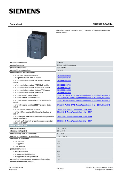
77 A 68 A 62 A
133 A 118 A 107 A
200 ... 480 V 200 ... 480 V -15 % 10 % -15 %
雷诺尔软起说明书1
4.1主回路………………………………………………………………………………………
4.2控制端子……………………………………………………………………………………
4.3控制电路端子连接…………………………………………………………………………
JJR系列软软起动器覆盖5.5~500KW广泛应用于冶金、化工、建筑、水泥、矿山、环保等所有工业领域的电机传动设备,是传统的星三角起动、电抗器起动、自耦降压起动器最理想的更新换代产品。
典型应用简介
◆水泵——利用泵控制功能,在起动和停止时,减少液流冲击所产生的泵流水锤现象,节省了系统维修费用;
◆球磨机——利用电压斜坡起动,减少齿轮转矩的磨损,减少维修工作量,即节省了时间又节约了开支;
※请检查你的工作电压是否正确
4.3.3通讯接口与模拟电流信号输出(参见图4.5.1)
◆标准485串口用于与上位PC机通讯,除了控制软起、软停,还可监控运行电流、故障状态等。
接口端子1:×1外引+5
接口端子4:×4接受器的反相输入和驱动器的反相输出端(B)
接口端子5:×5信号地
接口端子6:×6接受器输入和驱动器输出(A)
警告:
1、不允许输入端子(R、S、T)接到输出端U、V、W
2、不允许在输出端U、V、W接电容,否则会损坏起动器。
4.5基本电路图框图和端子
5.键盘及显示说明
JJR系列起动器设有五位显示和六个控制按键,见下图:
5.1各键说明:
RUN—起动键,在起动准备状态下按此键可使电机起动。
STOP/RST—停止/复位键,电机运行时按此键进入停车,编程状态或故障状态下按此键回到准备状态。
519细纱机说明书

519细纱机说明书3电气设备本机电气设备采用了程控器(PLC)及液晶数字显示器、接近开关及变频器(变频变速时)等一系列电子监测元器件和仪表,机电一体化程度高,可由程控器自动控制纺纱过程。
操作部分集中于车尾面板上,另在车头安装有主要的操作按钮,可在车头、车尾控制开车,使用方便。
3.1电源三相交流电380V50Hz(三相五线制)地线接地电阻<4Q电源进线位置见EJM128A-FT1(双速)或EJM128A-FT2(变频)地脚平面图。
3.2主要设备3.2.1用于主传动的三相交流异步电动机1台,本机的代号M4,装于车尾吸棉箱下。
420锭以下用15/81.5,420锭及以上至480锭以下用17/9kW,480锭及以上用18.5/11kW或22/11kW。
若采用变频变速时,主电机功率分别为15kW、17kW、18.5kW和22.5kW。
3.2.2用于断头吸棉风机的三相交流异步电动机1台,代号M1,装于车尾吸棉箱内,420锭及以下用1.5kW,420-480锭,用2.2kW,480锭以上用3kW。
3.2.3用于钢领板自动下降和复位的三相交流异步电动机1台,0.12kW,代号M2。
装于车头内。
3.2.4配气圈时用于气圈环上升和下降的三相交流异步电动机1台,0.37kW,代号M5,装于车头下部二墙板处。
3.2.5电气控制板上,装有程序控制器一台代号A1及全机的接触器、继电器等设备,装于车尾电气箱内。
3.2.6用于锭速及输出下罗拉线速度检测定长记录的接近开关2只,代号4S、5S,分别装于车尾内主轴上和输出下罗拉尾段处。
3.2.7用于显示锭子速度,前罗拉速度,捻度并显示各班长度及累计长度,能定长设定满管自动落纱的显示仪1台,代号A3,使用方法请参阅显示仪的使用说明书。
3.2.8用于主轴制动的单片式电磁离合器1只,代号Y2。
3.2.9行程开关2只,代号1S1、S3.它们分别控制满管,钢领板自动下降,开门停车等动作。
清灰时序控制仪
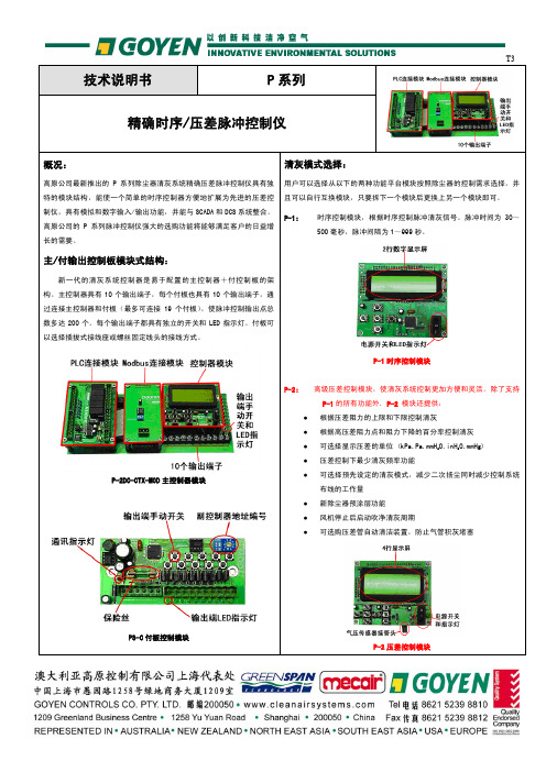
控制仪电路板尺寸
电路板
尺寸
英寸
毫米
主控制器线路板 10.3in x 4.3in 260mm x 108mm
小型付控制板 4.3in x 2.0in 108mm x 50mm
大型付控制板 6.3in x 2.4in 160mm x 60mm
外壳规范
电路板
说明
外观
金属外壳,可向上打开的封盖;插销关闭封盖方式;前部观察窗;
当系统安装有 P-2 时,可远程转换控制器的压差控制/时序控制模式 对系统中其它仪器进行监测(例如交流耦合粉尘监测探头) 远程启动时序清灰周期 在清灰系统的气包上可安装一个低压开关 取消运行状态报警 远程取消线圈故障、低气包压力、超高阻力和辅助仪器报警状态 可安装高原公司的气管清洁器,用于清洁连接压力阻力、或除尘器上的压差计的压差气管 远程监控控制器的供电状态 远程监控控制器脉冲周期或脉冲间隔的状态 远程监控脉冲控制器的电路状态 远程监控故障线圈的发生和位置 远程监控运行报警状态 远程监控压差上限报警状态 远程监控系统的实时压差阻力,自带输出电流
用户可以选择从以下的两种功能平台模块按照除尘器的控制需求选择,并 且可以自行互换模块,只要拆下一个模块后更换上另一个模块即可。
P-1:
时序控制模块,根据时序控制脉冲清灰信号。脉冲时间为 30~ 500 毫秒,脉冲间隔为 1~999 秒。
主/付输出控制板模块式结构:
新一代的清灰系统控制器是易于配置的主控制器+付控制板的架 构。主控制器具有 10 个输出端子,每个付板也具有 10 个输出端子,通 过连接主控制器和付板(最多可连接 19 个付板),使脉冲控制输出点总 数多达 200 个。每个输出端子都具有独立的开关和 LED 指示灯。付板可 以选择插拔式接线座或螺丝固定线头的接线方式。
- 1、下载文档前请自行甄别文档内容的完整性,平台不提供额外的编辑、内容补充、找答案等附加服务。
- 2、"仅部分预览"的文档,不可在线预览部分如存在完整性等问题,可反馈申请退款(可完整预览的文档不适用该条件!)。
- 3、如文档侵犯您的权益,请联系客服反馈,我们会尽快为您处理(人工客服工作时间:9:00-18:30)。
Micropin
Copper alloy, 50 miro-inch gold
Microsocket
Copper alloy, 50 micro-inch gold
Insulator
Jackscrew Retainer, Jackscrew Insert, Threaded Post, Polarizing
Stainless steel, passivated & lubricated Stainless steel, passivated Stainless steel, passivated
Post, Polarizing
Stainless steel, passivated
.170 (4.32) MAX.
color coded to MIL-STD-681
System I.
(L) 1
- 1/2" uninsulated solid #25
AWG gold plated copper.
(L) 2
- 1" uninsulated solid #25 AWG
gold plated copper.
* See Termination Codes shown below.
All Yellow H 009 H 010 H 011 H 013 H 017 H 042
Color Coded H 004 H 005 H 006 H 048 H 046 H 041
Solid Uninsulated Type (L) #25 AWG gold plated solid copper.
1 13 15 26 Contacts
1
61
7
10 11
11
16 19
16 Contacts**
10 18 28 28 Contacts**
17 34 51
1 18 35
21 44 66
51 Contacts
1 23 45 66 Contacts
MJSB/MJSU (unshrouded)
1
12
13
Polyester, black color Polyphenylene sulfide, black color Stainless steel, passivated Stainless steel, passivated Stainless steel, passivated Stainless steel, passivated
Shrouded Receptacle (16-28*-34)
MJSV/MJSR
A
.080 (2.03)
.065 (1.65)
.285 (7.24) MAX. D
C
Face View
A
MJS
.170 ± .010 (4.32 ± 0.25) POLARIZING PIN (OPTIONAL WITH LOSS OF CONTACT)
R MJS * - 26 P H 001
TERMINATION CODE*
(H) 001 - 18" , 7/34 strand, #26 AWG,
MIL-W-16878/4, Type E Teflon,
yellow.
(H) 003 - 18", 7/34 strand, #26 AWG,
MIL-W-16878/4, Type E Teflon,
.110 MAX. (2.79)
Receptacle
Part Number MJSB or MJSU-10P MJSB or MJSU-10S MJSB or MJSU-26P MJSB or MJSU-26S MJSB or MJSU-51P MJSB or MJSU-51S MJSB or MJSU-66P MJSB or MJSU-66S
Plug
B Max. .190 (4.83) .190 (4.83) .190 (4.83) .190 (4.83) .260 (6.60) .260 (6.60) .260 (6.60) .260 (6.60)
C Bsc. .290 (7.37) .290 (7.37) .690 (17.53) .690 (17.53) .940 (23.88) .940 (23.88) 1.190 (30.23) 1.190 (30.23)
RoHS COMPLIANCE
SERIES
INSULATOR MATERIAL
CONTACT ARRANGEMENT
CONTACT TYPE
TERMINATION TYPE
TERMINATION CODES
CONTACT TYPE P - Pin S - Socket
TERMINATION TYPE H - Insulated wire harness. I - Integral tail (MJSV-28S only). L - Solid - uninsulated wire. S - Solder pot to accept #26 AWG harness wire. T - Thru bundle pigtail (MJSV-28P only).
元器件交易网
Micro Center Jackscrew
MJS
The MJS jackscrew series provides a reliable interconnect for board-to-board, board-to-cable and in-line cable-to-cable applications. Layouts accommodating up to 76 MICROPIN/MICROSOCKETTM contacts are available, with the same wide range of options as are offered with the other MICRO Line products offered in this catalog.
22
23
34
34 Contacts MJSV (shrouded)
Identification numbers are for reference only and do not appear on connectors.
*Low profile configuration **MJSV & MJSR
1-64 UNC-2A THREAD
A Max. .378 (9.60) .378 (9.60) .778 (19.76) .778 (19.76) 1.028 (26.11) 1.028 (26.11) 1.280 (32.51) 1.280 (32.51)
1-64 UNC-2B THREAD
.332 (8.43) MAX.
Harness Type (H) #26 AWG per MIL-W-16878/4 Type E Teflon, 7/34 stranded.
Length
All Yellow
Color Coded
3 (76.2)H 0源自0H 0276 (152.4)
H 019
H 016
8 (203.2)
H 026
1-64 UNC-2B THREAD B
1-64 UNC-2A THREAD
Plug
.205 (5.21) MAX. .090 ± .010 (2.29 ± 0.25)
.285 (7.24) MAX.
B
.110 (2.79) MAX.
C
Face View
SHROUDED STANDARD MATERIALS AND FINISHES
Copper alloy, 50 miro-inch gold
Microsocket
Copper alloy, 50 micro-inch gold
Insulator
Diallyl phthalate, green color or polyetherimide, natural color
Jackscrew Retainer, Jackscrew Insert, Threaded
How to Order
SERIES MJS - Micro Center Jackscrew
INSULATOR MATERIAL B - Diallyl phthalate V - Polyester U - Polyetherimide R - Polyphenylene sulfide
CONTACT ARRANGEMENTS Unshrounded Receptacle: 10, 26, 51, 66 Shrouded Receptacle; 10, 26, 34, 38, 42, 76 Low Profile Plug and Receptacle (shrouded): 28
Receptacle
.145 (3.68) DIA. MAX.
Part Number
A Max.
B Max.
C
D
Ref.
± .006 (0.15)
MJSV or MJSR-16P
.700 (17.78)
.345 (8.76)
.545 (13.84)
.175 (4.45)
MJSV or MJSR-16S
Termination
Termination
Code
Length
Code
Length
L61 .125 (3.18) L14 .750 (19.05)
L56 .150 (3.81) L2 1.000 (25.40)
L57 .190 (4.83) L7 1.500 (38.10)
