lab3动态路由
配置动态路由RIP(三个三层交换机Vlan互通)

配置动态路由RIP(三个三层交换机Vlan互通)网络拓扑如下:配置如下:第一个交换机:1、重命名设备Switch#conf tEnter configuration commands, one per line. End with CNTL/Z.Switch(config)#hostname S12、创建Vlan 10、20、30S1#vlan databaseS1(vlan)#vlan 10 name toyotaVLAN 10 added:Name: toyotaS1(vlan)#vlan 20 name LexusVLAN 20 added:Name: LexusS1(vlan)#vlan 30 name ShareVLAN 30 added:Name: Share3、将网口1-5给Vlan10,网口21-24给Vlan20,将G1做扩展相互通信使用.S1(config)#interface range fastEthernet 0/1-5S1(config-if-range)#switchport access vlan 10S1(config-if-range)#exitS1(config)#interface range fastEthernet 0/21-24S1(config-if-range)#switchport access vlan 20S1(config-if-range)#exitS1(config)#interface gigabitEthernet 0/1S1(config-if)#switchport access vlan 30S1(config-if)#exit4、Vlan 配置上IPS1(config)#interface vlan 10S1(config-if)#ip address 10.6.1.2 255.255.255.0S1(config-if)#exitS1(config)#interface vlan 20S1(config-if)#ip address 10.6.2.2 255.255.255.0S1(config-if)#exitS1(config)#interface vlan 30S1(config-if)#ip address 10.6.3.2 255.255.255.0S1(config-if)#exit5、台式机测试网络,测试OKA、如发现仅能ping所属Vlan的地址,需要在三层启动IP routing6、其他二个交换机配置类似,需注意中间的S2交换机,需将G0/1、G0/2都划给Vlan30,G0/1连接S1,G0/2连接S37、配置动态路由,并查看路由状态。
LAB3 局域网组网入门

实验三局域网组网入门一、实验目的(1)了解局域网组网的基本组件;(2)掌握局域网组件之间的互连;(3)初步掌握小型网络的拓朴设计;(4)学会使用网络模拟器Packet Tracer 软件。
二、实验设备CISCO公司的Packet Tracer 5.3 软件,该软件可以模拟网络设计与网络组建。
网络拓朴图(两层结构的网络):三、实验内容1、安装Packet Tracer 软件。
2、使用网络模拟器Packet Tracer设计如上图所示的网络拓朴。
3、设置44、测试网络连通性:(1)PC0 ping PC1,是否通?是(1)PC0 ping PC2,是否通?是(1)PC0 ping Server0,是否通?是(1)PC2 ping Server0,是否通?是5四、讨论1、说明两种查看计算机IP 地址的方法,一种查看MAC地址的方法。
答:1:右键网络连接属性查看IP地址。
2:通过运行ipconfig查看计算机IP地址。
3:查看MAC地址使用命令运行ipconfig /all。
2、如何确认计算机与交换机之间是否连好线?答:1:查看交换机端口对应的指示灯是否已亮,如已亮说明网线已经连好。
2:查看计算机的本地连接,如出现“网络电缆没有插好”的提示,或本地连接图标上出现小红叉则说明网线没有连好。
3、如何查看网卡是否正常工作?答:1:ping127.0.0.1,ping通了就说明网卡正常工作。
2:单击网络适配器,双击相应的网络适配器,在出现网络适配器的属性窗口检测网卡是否工作正常。
4、如何使用IP地址127.0.0.1?答:可以通过ping来对回送地址连通性的测试来检查网卡工作是否正常。
5、如果连接在同一局域网中的两台计算机具有相同的IP地址,会出现什么情况?答:网络连接出现三角形警告符号,无法连接使用网络。
6、如果在局域网中,某台计算机ping 同一网段的其它计算机均通,但仅一台主机不通,则故障的可能原因有哪些?答:不通的主机网卡有问题或者网络设置不正确或者物理线路有问题。
NA-NP-IE实验

0
08/05/2009
央邦IT实验室
暑期网络工程大学 实验手册
央邦 IT 培训实验手册
CCNA 部分
Lab 1 路由器的基本配置 实验要求
1. 2. 3. 4. 5. 6. 7. 8. 掌握路由器的用户模式、特权模式、配置模式的切换。 配置路由器的特权密码,明文密码为 ccna、密文密码为 cisco。 配置路由器的 console 登录密码为 cisco、远程登录密码是 cisco。 配置路由器 Ethernet 0/0 的接口 IP 为 10.50.x.1/8,并打开接口 掌握常用的 show 命令 使用 tftp 软件,将路由器上的 IOS 映像文件下载到本地计算机作备份。 用本地计算机的 IOS 映像文件上传到路由器,掌握如果升级路由器 IOS。 将 flash 中的 IOS 映像文件删除,在 ROMMON 模式下恢复路由器的 IOS。
央邦IT实验室
暑期网络工程大学 实验手册
CCNA部分 .............................................................................................................................................. 1 LAB 1 路由器的基本配置 ................................................................................................................... 1 LAB 2 配置静态路由 .......................................................................
lab 3 DHCP服务器配置与管理-学生版

实验3 DHCP服务器配置与管理【实验目的】1.掌握配置IP地址的方法;2.安装和配置DHCP服务器。
【实验设备和环境】1.多台具备Windows Server 2008 2R系统的计算机和局域网网络环境;2.6人一组。
【实验内容和测试要求】实验ip规划和准备:DHCP服务器端的网络配置设置:必须有静态的IP地址和子网掩码。
实验中,需设置自己的主机为当前的DHCP服务器端。
DHCP服务器的TCP/IP设置如下:DHCP服务器的TCP/IP设置如下:IP地址192.168.组号.学号后两位子网掩码255.255.255.0网关192.168.组号.2541.安装DHCP服务器,在“开始->管理工具->服务器管理器->添加角色->”,在向导里面选择“DHCP”。
操作如下图2.继续相关设置第一种配置DHCP服务器方法(安装时配置)3.选择网络连接绑定4、确认安装选择之后,开始安装。
5、安装结果6、查看安装结果第二种配置DHCP服务器方法(安装后配置)2.配置DHCP服务器,要求如下:(1) 新建作用域名为dhcp学号后两位(2) IP地址的范围为192.168.组号.2-192.168.组号.240中的一段// 1-30 31-60(小组内自行分配)(3) 掩码长度为24位(4) 排除地址范围为192.168.组号.学号后两位(5) 租约期限3小时(6) 该DHCP服务器同时向客户机分配以下地址:①路由器(默认网关) 的IP地址为192.168.组号.254②DNS的IP地址为192.168.组号.1,父域名称为xky学号后两位.cn,服务器名为dns.xky学号后两位.cn。
(7) 将IP地址192.168.组号.106保留。
(8) 激活此作用域。
3.DHCP设置后的验证(1) 在客户端:①将客户机设置成自动获取ip地址。
②cmd 进入命令界面利用ipconfig /all 可查看自动获取的Ip地址和相关配置信息;利用ipconfig /release 可释放获得的IP地址;利用ipconfig /renew 可重新获得IP地址。
LAB-3:传输控制TCP及用户数据报UDP协议分析-2013
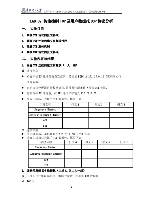
LAB-3:传输控制TCP及用户数据报UDP协议分析一.实验目的1.掌握TCP协议的报文格式2.掌握TCP连接的建立和释放过程3.理解TCP重传机制4.掌握UDP协议的报文格式二.实验内容与步骤1.检查TCP连接的建立和释放(一人一组)1)连接建立●检查本机IP地址是否设置正常,是否能PING通172.27.0.20(实训中心内部服务器)●启动协议分析器进行数据捕获,并设置过滤条件(提取TCP协议)●打开本机IE浏览器,在URL地址栏中输入172.27.0.20●检查主机捕获的握手TCP数据包,填写下表:2)●关闭浏览器,本机断开与172.27.0.20的TCP连接●2.编辑并发送UDP数据报(主机A、B二人一组)1)主机A打开协议编辑器,编辑并发送主机B的UDP数据报:a)MAC层:目的MAC地址:接收方MAC地址源MAC地址:发送方MAC地址协议类型或数据长度:0800,即IP协议b)IP层:总长度:包括IP层、UDP层和数据长度高层协议类型:17,即UDP协议首部校验和:其它所有字段填充完毕后填充此字段源IP地址:发送方IP地址目的IP地址:接收方IP地址c)UDP层:源端口1030,目的端口大于1024的端口号有效负载长度:UDP层及其上层协议长度d)其它字段默认,计算校验和2)在主机B上启动协议分析器捕获数据,并设置过滤条件(提取UDP协议)3)主机A发送已编辑好的数据报4)主机B停止捕获数据,在捕获到的数据中查找主机A所发送的数据报5)记录主机B捕获到的UDP数据格式:三.实验结果分析与思考1. 实验步骤1中,结合TCP连接过程中所填的表,理解TCP的三次握手建立连接和四次握手的释放连接过程,理解序号、确认号等字段在TCP可靠连接中所起的作用。
2.为什么在TCP连接过程中要使用三次握手?如果不这样做可能会出现什么情况?3.实验步骤2中计算UDP协议的“校验和”时要包括哪些内容?为什么要包含“伪首部”?4.试比较UDP和IP的不可靠程度?四.实验报告1.按上述实验步骤与内容撰写实验报告(抄袭他人实验结果,双方均不计成绩)2.说明实验网络拓朴结构、时间、地点及同级成员名单。
思科 路由与交换基础实验lab3
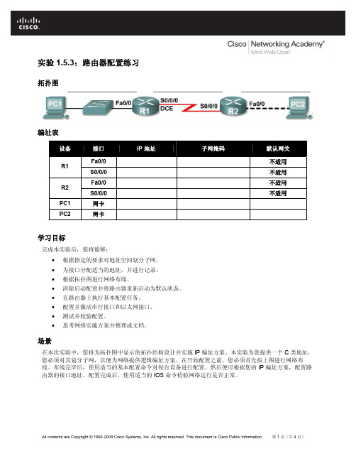
实验 1.5.3:路由器配置练习拓扑图编址表设备接口IP 地址子网掩码默认网关Fa0/0 不适用R1S0/0/0 不适用Fa0/0 不适用R2S0/0/0 不适用PC1 网卡PC2 网卡学习目标完成本实验后,您将能够:•根据指定的要求对地址空间划分子网。
•为接口分配适当的地址,并进行记录。
•根据拓扑图进行网络布线。
•清除启动配置并将路由器重新启动为默认状态。
•在路由器上执行基本配置任务。
•配置并激活串行接口和以太网接口。
•测试并校验配置。
•思考网络实施方案并整理成文档。
场景在本次实验中,您将为拓扑图中显示的拓扑结构设计并实施 IP 编址方案。
本实验为您提供一个 C 类地址,您必须对其划分子网,以便为网络提供逻辑编址方案。
在开始配置之前,您必须首先按上图进行网络布线。
布线完毕后,使用适当的基本配置命令对每台设备进行配置。
然后便可根据您的 IP 编址方案,配置路由器的接口地址。
配置完成后,使用适当的 IOS 命令检验网络运行是否正常。
任务 1:对地址空间划分子网。
步骤 1:研究网络要求。
在您的网络设计中,您可以使用 192.168.1.0/24 地址空间。
实验网络的要求如下:•连接到路由器 R1 的网络需要足够的 IP 地址来支持 20 台主机。
•连接到路由器 R2 的网络需要足够的 IP 地址来支持 20 台主机。
•路由器 R1 和路由器 R2 之间的链路的每一端都需要 IP 地址。
(注意:网络设备的接口也是主机 IP 地址,上述编址方案包括了这些地址。
)步骤 2:创建网络设计时请思考以下问题。
该网络需要多少个子网? ____________________该网络的子网掩码是什么(以点分十进制格式表示)? ____________________ 以斜杠格式表示的网络子网掩码是什么? ____________________每个子网可支持多少台主机? ____________________步骤 3:为拓扑图分配子网地址。
LAB配置策略路由PBR

05
lab配置策略路由pbr总结
实验收获
深入理解了策略路由PBR的实现原理
01
通过配置策略路由,可以实现数据包根据特定规则进行路由,
提升了网络的灵活性和可扩展性。
学会了Lab配置方法
02
在实验中采用Lab配置方式,可以更加直观地展示网络设备的
配置过程,提高配置效率。
掌握VPC的配置和调试技巧
03
通过实验,熟悉了VPC的配置和调试技巧,可以更好地应对复
杂网络场景。
实验不足之处
实验过程中没有考虑到负载均衡的问题
在实验过程中,没有对负载均衡进行详细的研究和配置,导致网络设备在高负载 时可能出现性能瓶颈。
实验环境与实际场景的差异
由于实验环境的限制,实验中使用的网络拓扑和设备型号可能与实际场景存在差 异,影响实验结果的可推广性。
交换机
02
Cisco 3750,具备高性能、灵活性和可扩展性,支持二层和三
层功能。
PC机
03
运行Windows或Linux操作系统的计算机,用于网络配置和测
试。
02
策略路由基本概念
什么是策略路由
策略路由是一种网络路由技术,它可以根据不同的路由策略 将数据包从一个网络转发到另一个网络。
策略路由可以根据数据包的目的地址、源地址、传输协议等 因素来选择不同的路由路径,从而实现更加灵活和智能的路 由控制。
未来改进方向
完善负载均衡的配置
在未来的实验中,可以深入研究负载均衡的配置方法,实现网络设备的负载均衡,提高网 络设备的性能表现。
丰富实验环境和拓扑
可以尝试使用更多种类的网络设备和应用场景,丰富实验环境和拓扑,提高实验结果的可 推广性。
Lab3 多路复用器设计
实验三多路复用器设计(数据选择器)一、 实验前准备1.EXCD-1可编程片上系统开发板;2.下载线;3.5V电源。
二、 实验目的1.学习使用ISE软件,并用VHDL语言设计多路复用器;2.使用USB电缆下载逻辑电路到FPGA,并能根据电路原理调试电路使其正常工作;3.掌握数字电路集成设计的过程。
三、 实验原理多路复用器即数据选择器,用来将N个输入通道的数据复用到一个输出通道上,多路复用器在数字系统中有着非常重要的应用。
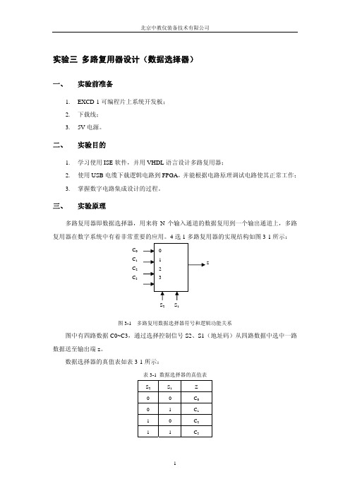
4选1多路复用器的实现结构如图3-1所示:图3-1 多路复用数据选择器符号和逻辑功能关系图中有四路数据C0~C3,通过选择控制信号S2、S1(地址码)从四路数据中选中一路数据送至输出端z。
数据选择器的真值表如表3-1所示:表3-1 数据选择器的真值表S2S1 Z0 0 C00 1 C11 0 C21 1 C3四、 实验内容用VHDL语言设计四选一数据选择器,其中拨码开关SW3~SW0为数据端,拨码开关SW7~SW6为选择控制信号输入端, D0为输出端,通过SW7和SW6的值来确定选择哪一路输出。
四选一数据选择器真值表如下表所示:表3-2 四选一数据选择器真值表控制端(s)信号端(c3~c0)输出端(z) SW7 SW6 SW3 SW2 SW1 SW0 D00 0 ×××0 亮0 0 ××× 1 灭0 1 ××0 ×亮0 1 ×× 1 ×灭1 0 ×0 ××亮1 0 × 1 ××灭其他其他0 ×××亮其他其他 1 ×××灭由表3-4可知,当控制信号输入端SW7、SW6为00时,选中四路输入数据中的SW0,此时输出端D0为SW0的数据,实验现象表现为SW0可以控制输出D0 的亮灭,其他三个数据输入端SW1、SW2和SW3的数据没有被选择,即SW1、SW2和SW3不能控制输出D0的状态。
LAB配置策略路由PBR

测试法
在配置策略路由之前和之后,分别进行网络性能测试,比较测试结果
以验证配置的效果。
结果展示与分析
性能提升
负载均衡
安全增强
灵活控制
通过策略路由的配置,网络性能 得到显著提升,响应时间缩短, 吞吐量增加。
策略路由可以实现网络流量的负 载均衡,提高网络资源利用率, 降低单台服务器的负载。
通过策略路由,可以实现网络流 量的安全控制,有效防范网络攻 击,增强网络安全性能。
网络拓扑
Lab环境
实验环境包括两个汇聚层交换机、两个接入层交换机、两个汇聚层路由器和 一个核心路由器。
网络拓扑结构
核心路由器通过汇聚层路由器与两个汇聚层交换机相连,每个汇聚层交换机 下面连接两个接入层交换机,每个接入层交换机下面连接三个PC,共计24个 PC。
02
lab配置
配置物理接口
1 2
连接性
lab配置策略路由pbr
xx年xx月xx日
目 录
• 实验环境及网络拓扑 • lab配置 • pbr实验 • 策略路由实验 • 结果验证与分析 • 总结与展望
01
实验环境及网络拓扑
实验环境
CentOS
操作系统采用CentOS,需要安装所需的网络管理工具和命 令行工具。
Vmware ESXi
虚拟化平台使用Vmware ESXi,创建虚拟机并配置网络连接 。
设备配置
网络连接配置:配置各设备之间的网络连接关系,包 括IP地址、子网掩码、网关等。
pbr配置流程
确定路由策略
明确数据包的源、目的地址和传输协议,以及相 应的路由策略。
配置策略路由
根据路由策略,配置数据包转发的下一跳地址或 传输协议。
实验3动态路由的设置RIP

动态路由的设置(2学时)【实验名称】动态路由配置(RIP V2配置)。
【实验目的】掌握在路由器上配置RIP V2。
【技术原理】RIP(Routing Information Protocols,路由信息协议)是应用较早、使用较普遍的IGP(Interior Gateway Protocol,内部网关协议),适用于小型同类网络,是典型的距离矢量(distance-vector)协议。
RIP协议跳数做为衡量路径开销的,RIP协议里规定最大跳数为15。
RIP协议有两个版本RIPv1和RIPv2。
RIPv1属于有类路由协议,不支持VLSM(变长子网掩码),RIPv1是以广播的形式进行路由信息的更新的;更新周期为30秒。
RIPv2属于无类路由协议,支持VLSM(变长子网掩码),RIPv2是以组播的形式进行路由信息的更新的,组播地址是224.0.0.9。
RIPv2还支持基于端口的认证,提高网络的安全性。
【实现功能】实现网络的互连互通,从而实现信息的共享和传递。
【实验设备】路由器3台,交换机3台,PC6台,连线若干【实验拓扑】实验要求按照上述网络拓扑图和实验指导进行配置,并对所有主机和路由其端口的IP地址进行设置,然后进行动态路由的设置,测试各子网之间的连通性。
查看各路由器的路由表,应能看到所有5个子网。
实验指导1、各路由器的路由配置如下Router0的配置Router>enRouter#conf tEnter configuration commands, one per line. End with CNTL/Z.Router(config)#int f0/0Router(config-if)#ip address 192.168.5.1 255.255.255.0Router(config-if)#no shutdownRouter(config-if)#int s2/0Router(config-if)#ip address 192.168.1.1 255.255.255.0Router(config-if)#clock rate 64000 !DCE端配置时钟频率Router(config-if)#no shutdownRouter(config-if)#exitRouter(config)#route rip !配置RIP路由协议Router(config-router)#network 192.168.1.0 !声明路由器的直连网络Router(config-router)#network 192.168.5.0Router(config-router)#version 2 !RIP版本为RIPv2Router(config-router)#exitRouter(config)#exitRouter#show ip route !查看路由表Codes: C - connected, S - static, I - IGRP, R - RIP, M - mobile, B - BGPD - EIGRP, EX - EIGRP external, O - OSPF, IA - OSPF inter areaN1 - OSPF NSSA external type 1, N2 - OSPF NSSA external type 2E1 - OSPF external type 1, E2 - OSPF external type 2, E - EGPi - IS-IS, L1 - IS-IS level-1, L2 - IS-IS level-2, ia - IS-IS inter area* - candidate default, U - per-user static route, o - ODRP - periodic downloaded static routeGateway of last resort is not setC 192.168.1.0/24 is directly connected, Serial2/0R 192.168.2.0/24 [120/1] via 192.168.1.2, 00:00:07, Serial2/0R 192.168.3.0/24 [120/2] via 192.168.1.2, 00:00:07, Serial2/0R 192.168.4.0/24 [120/1] via 192.168.1.2, 00:00:07, Serial2/0C 192.168.5.0/24 is directly connected, FastEthernet0/0Router#Router1的配置Router>enRouter#conf tEnter configuration commands, one per line. End with CNTL/Z. Router(config)#int s2/0Router(config-if)#ip add 192.168.1.2 255.255.255.0Router(config-if)#no shutdownRouter(config-if)#Router(config-if)#int f0/0Router(config-if)#ip add 192.168.4.1 255.255.255.0Router(config-if)#no shutdownRouter(config)#int s3/0Router(config-if)#ip add 192.168.2.1 255.255.255.0Router(config-if)#clock rate 64000Router(config-if)#no shutdownRouter(config-if)#exitRouter(config)#route ripRouter(config-router)#network 192.168.1.0Router(config-router)#network 192.168.4.0Router(config-router)#network 192.168.2.0Router(config-router)#version 2Router(config-router)#exitRouter(config)#exitRouter#show ip routeCodes: C - connected, S - static, I - IGRP, R - RIP, M - mobile, B - BGPD - EIGRP, EX - EIGRP external, O - OSPF, IA - OSPF inter areaN1 - OSPF NSSA external type 1, N2 - OSPF NSSA external type 2E1 - OSPF external type 1, E2 - OSPF external type 2, E - EGPi - IS-IS, L1 - IS-IS level-1, L2 - IS-IS level-2, ia - IS-IS inter area* - candidate default, U - per-user static route, o - ODRP - periodic downloaded static routeGateway of last resort is not setC 192.168.1.0/24 is directly connected, Serial2/0C 192.168.2.0/24 is directly connected, Serial3/0R 192.168.3.0/24 [120/1] via 192.168.2.2, 00:00:20, Serial3/0C 192.168.4.0/24 is directly connected, FastEthernet0/0R 192.168.5.0/24 [120/1] via 192.168.1.1, 00:00:12, Serial2/0 Router#Router2的配置Router>enRouter#conf tEnter configuration commands, one per line. End with CNTL/Z. Router(config)#int s2/0Router(config-if)#ip add 192.168.2.2 255.255.255.0Router(config-if)#no shutdownRouter(config-if)#int f0/0Router(config-if)#ip add 192.168.3.1 255.255.255.0Router(config-if)#no shutdownRouter(config-if)#exitRouter(config)#route ripRouter(config-router)#network 192.168.2.0Router(config-router)#network 192.168.3.0Router(config-router)#version 2Router(config-router)#exitRouter(config)#exitRouter#show ip routeCodes: C - connected, S - static, I - IGRP, R - RIP, M - mobile, B - BGPD - EIGRP, EX - EIGRP external, O - OSPF, IA - OSPF inter areaN1 - OSPF NSSA external type 1, N2 - OSPF NSSA external type 2E1 - OSPF external type 1, E2 - OSPF external type 2, E - EGPi - IS-IS, L1 - IS-IS level-1, L2 - IS-IS level-2, ia - IS-IS inter area* - candidate default, U - per-user static route, o - ODRP - periodic downloaded static routeGateway of last resort is not setR 192.168.1.0/24 [120/1] via 192.168.2.1, 00:00:15, Serial2/0C 192.168.2.0/24 is directly connected, Serial2/0C 192.168.3.0/24 is directly connected, FastEthernet0/0R 192.168.4.0/24 [120/1] via 192.168.2.1, 00:00:15, Serial2/0R 192.168.5.0/24 [120/2] via 192.168.2.1, 00:00:15, Serial2/02、PC机的配置略,但要注意PC0、PC1的网关为192.168.5.1,网络地址为192.168.5.0PC2、PC31的网关为192.168.4.1,网络地址为192.168.4.0PC4、PC5的网关为192.168.3.1,网络地址为192.168.3.0 测试利用PING测试,任意两台PC之间均能连通。
清华大学操作系统lab3实验报告范文
清华大学操作系统lab3实验报告范文实验3:虚拟内存管理练习1:给未被映射的地址映射上物理页ptep=get_pet(mm->dir,addr,1);if(ptep==NULL){//页表项不存在cprintf("get_pteindo_pgfaultfailed\n"); gotofailed;}if(某ptep==0){//物理页不在内存之中//判断是否可以分配新页if(pgdir_alloc_page(mm->pgdir,addr,perm)==NULL){ cprintf("pgdir_alloc_pageindo_pgfaultfailed\n"); gotofailed;}}ele{if(wap_init_ok){tructPage某page=NULL;ret=wap_in(mm,addr,&page);if(ret!=0){//判断页面可否换入cprintf("wap_inindo_pgfaultfailed\n");gotofailed;}//建立映射page_inert(mm->pgdir,page,addr,perm);wap_map_wappable(mm,addr,page,1);}ele{cprintf("nowap_init_okbutptepi%某,failed\n",某ptep); gotofailed;}}ret=0;failed:returnret;}练习2:补充完成基于FIFO算法_fifo_map_wappable(tructmm_truct某mm,uintptr_taddr,tructPage某page,intwap_in){lit_entry_t某head=(lit_entry_t某)mm->m_priv;lit_entry_t某entry=&(page->pra_page_link);aert(entry!=NULL&&head!=NULL);lit_add(head,entry);return0;}pra_page_link用来构造按页的第一次访问时间进行排序的一个链表,这个链表的开始表示第一次访问时间最近的页,链表的尾部表示第一次访问时间最远的页。
Lab 3 - Firewall

Aruba Advanced Technical TrainingLab 3Firewalls and RolesGoals∙Configure destinations and services∙Configure firewall rules∙Configure firewall policies∙Create and configure roles∙Apply firewall policies to interfacesConfigure Destination and Service Aliases NetdestinationThe netdestination command allows multiple networks and ranges of networks to be configured with easy to understand alias names assigned to them.1.Set up a new netdestination called “Internal_Network” where “x” equals yourTable’s su bnet.CLI:# conf t(config) # netdestination Internal_Network(config-dest) # network 172.16.x.0 255.255.255.0(config-dest) # endGUI:a.Navigate the following menu path Configuration→Security→Advanced→Destinationsb.Click on the Add button to begin adding a new destination the destination “Internal_Network”, and click the Add buttond.In the Add Rule section, use the following settings:i.Rule Type = networkii.IP Address = 172.16.x.0work Mask/Range = 255.255.255.0e.Click on the Add button to accept these rulesf.Click on the Apply button to save this netdestinationThis command could be used to create netdestinations to be used with firewallrules to allow access to certain portions of the network, but not others.2.Create netdestinations for the other subnets in the class, including the networkthat the server is connected to (11.2.1.0/24). Use “Backbone” as the name for thenetwork the server is connected to, and “Tablex_Network” as the namingconvention for each of the netdestinations.Netservicenetservice is similar to “netdestination”, but allows you to create aliases for commonly used network protocols such as HTTP, FTP, SMTP, etc.1.Examine the pre-configured services. Then create a new service called “svc-test1”. This service will use TCP po rt 1818.CLI:# show running-config# conf t(config) # netservice svc-test1 tcp 1818(config) # endGUI:a.Navigate the following menu path Configuration→Security→Advanced→Servicesb.Click on the Add button to begin adding a new servicec.In the Add Rule section, use the following settings:i.Service Name = svc-test1ii.Protocol = TCPiii.Starting Port = 1818d.Click on the Apply button to save this netservice2.Services can also exist across a range of port numbers. For example, “svc-dhcp”uses UDP ports 67 and 68. Create a new service “svc-test2” with a range of UDP ports from 1900 to 19213.Services can also be defined by IP protocol. For example, “svc-esp” is IPprotocol 50. Create a new service “svc-test3” with an IP protocol number 250. Create Firewall PoliciesFirewall rules can be constructed using netdestination and netservice aliases, or they can be created using specific addresses. Using names instead of addresses can simplify the configuration and make it easier to understand.1.Examine the pre-configured firewall policies. Then create a new firewall policycalled “Internet_Only”. This policy can be used to restrict access only to theInternet by denying access to the internal network. You will use theInternal_Network netdestination you created early to accomplish this. Whenreviewing the firewall policies using the CLI, look for “ip access-list session”, which is what all firewall policies begin with. Also notice that the use ofnetservice names makes the policies very easy to understand.CLI:# show running-config# conf t(config)# ip access-list session Internet_Only(config-sess-Internet_Only)# user alias Internal_Network any deny (config-sess-Internet_Only)# user any any permit(config-sess-Internet_Only)# endGUI:a.Navigate the following menu path Configuration→Security→Policiesb.Click on the Add button to begin adding a new Firewall Policy the policy “Internet_Only”, and click the Add buttond.In the Rules section, add your first rule using the following settings:i.Source = userii.Destination = Aliasiii.Alias = Internal_Networkiv.Service = anyv.Action = drope.Add a second rule to this policy using the following settings:i.Source = userii.Destination = anyiii.Service = anyiv.Action = permitf.The rules must be in this order since the firewall processes them sequentiallyand stops processing once a match is found.g.When the rules are properly created, click the Apply button to save this policy2.Now insert a new line into the firewall policy you just created. The purpose ofthis new rule will be to deny access to one more network. The rule needs to be at priority/position 2, so that it is executed before the “any any permit” statement:CLI:# conf t(config)# ip access-list session Internet_Only(config-sess-Internet_Only)# user network 124.13.2.0255.255.255.0 any deny position 2(config-sess-Internet_Only)# endGUI:a.Navigate the following menu path Configuration→Security→Policiesb.Next to the “Internet_Only” policy, click on the Edit button to begin editingthis Firewall Policyc.In the Rules section, click on the Add button to add a new rule using thefollowing settings:i.Source = userii.Destination = networkiii.Host IP = 124.13.2.0iv.Mask = 255.255.255.0v.Service = anyvi.Action = dropd.After all of the settings are entered, click on the Add button to accept this newrule, and then click on the up arrow next to the rule to move it to the 2ndposition in the list.e.Click on Apply to save the changes to this firewall policy.Create RolesOnce firewall policies have been defined, they need to be applied to roles. In this section, you will create a new role and edit an existing role. As part of these tasks, you will assign firewall policies to these roles1.Examine the pre-configured user-roles. Then create a role named “employee” andthen assign the “allowall” pol icy to the role.CLI:# show running-config | begin user-role# conf t(config)# user-role employee(config-role)# session-acl allowall(config-role)# endGUI:a.Navigate the following menu path Configuration→Security→Rolesb.Click on the Add button to begin adding a new User Rolec.In the Role Name field, enter “employee”d.In the Firewall Policies section, click on Add to add a policy to this rolee.Select the radio button next to “Choose from Configured Policies” and selectthe policy “allowall” from the dro p down menu. Click on the Done button to accept this firewall policy.f.Scroll to the bottom of the window, and click on the Apply button to savethese changes.2.Now view the role you just created. First, view the summary of all roles:# show rights3.Nex t, view the rights for the role “employee”:# show rights employee4.There is an existing role called “guest”. View the rights for the role and thenmodify the role to allow Internet access using the firewall policy you created earlier.CLI:# show rights guest# conf t(config)# user-role guest(config-role)# session-acl Internet_Only(config-role)# endGUI:a.Navigate the following menu path Configuration→Security→Rolesb.Next to the “Guest” role, click on the Edit button to begin editing this UserRole.c.In the Firewall Policies section, click on Add to add a policy to this role.d.Select the radio button next to “Choose from Configured Policies” and select“Internet_Only” from the drop down selection box.e.Click on the Done button to accept this policy.f.At the bottom of the window, click on Apply to save the changes to this role.View ACL and Firewall Activitye the following command to view firewall and ACL activity. This is animportant command to use when troubleshooting firewall problems. Note thatsince you applied this policy to an unused port, you will not have any data.CLI:# show acl hitsGUI:a.Navigate the following menu path Monitoring→Switch → Firewall Hits Save ConfigDon’t forget to save all of your configuration changes by typi ng the commandcopy running-config startup-config (or “Save Configuration” in the GUI). This saves the running-config to flash (startup-config).ExerciseNow that you have become familiar with firewalls, role derivations, and ACLs, use these skills to create a realistic configuration for a customer. You may work together with the entire class to solve this exercise. This is to be a pencil and paper exercise. Do not configure these policies on the switch.The customer is a large financial services firm that wants to deploy secure wireless access. They have four classes of users on the network – employees, contractors, guests, and the IT staff. Here are the important IP addresses for this customer:Corporate network: 10.16.0.0/16Mail server: 10.16.22.5 and 10.16.22.6Intranet server: 10.16.22.9DNS server: 10.16.22.11, 10.16.23.11, and 10.16.26.11DHCP server: 10.16.22.10Out-of-band network management subnet: 10.16.30.0/24The company would like employees to have full access to the network, except for the out-of-band network management subnet. Employees should also have full Internet access.Guests should have only Internet access using HTTP, POP3, SMTP, IPSEC, and PPTP, the corporate DNS and DHCP servers and should be prevented from accessing any other network service inside the company.Contractors should have the same access that normal employees have, but should not be allowed to use the Internet.The IT staff should have full access to the entire network.。
ospfv3的原理和应用

OSPFv3的原理和应用1. OSPFv3简介OSPFv3(Open Shortest Path First version 3)是一种用于IPv6网络的动态路由协议。
它是IPv6网络中最常用的内部网关协议(IGP),用于计算和选择最佳路径,实现IPv6网络的自动路由分发。
2. OSPFv3的工作原理OSPFv3基于链路状态路由协议(Link State Routing Protocol),通过交换链路状态信息来计算网络中的最短路径。
下面是OSPFv3的工作原理的步骤:1.邻居发现:路由器通过发送Hello消息来建立与相邻路由器的邻居关系。
Hello消息中包含路由器的标识和接口及其启用OSPFv3状态的信息。
2.建立邻居关系:当两个路由器接收到对方的Hello消息,并验证消息中的信息正确时,它们就会建立邻居关系。
邻居关系的建立要求路由器具有相同的Area ID。
3.链路状态数据库同步:邻居关系建立后,路由器会交换链路状态数据库(Link State Database)中的信息,使路由器之间的数据库保持同步。
链路状态数据库记录了网络中所有路由器和链路的信息。
4.最短路径计算:路由器使用Dijkstra算法来计算网络中的最短路径。
该算法基于链路状态数据库中的信息,通过计算最短路径树来确定每个目的地的最短路径。
5.路由表更新:最短路径计算完成后,每个路由器都会更新自己的路由表,将所选的最佳路径添加到路由表中。
这样,路由器就能够根据路由表中的信息来转发数据包。
3. OSPFv3的应用OSPFv3广泛应用于IPv6网络中,为网络提供高效的动态路由功能。
下面是OSPFv3在实际应用中的几个方面:1.企业网络:OSPFv3被广泛用于企业网络中,特别是大型企业网络。
它能够自动计算最佳路由,确保数据在网络中的快速传输。
2.服务提供商网络:许多大型互联网服务提供商(ISP)使用OSPFv3作为核心路由协议,以提供高可靠性和高性能的网络连接。
两台三层交换机单区域OSPF动态路由实验
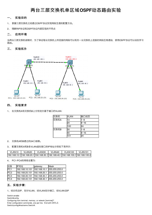
两台三层交换机单区域OSPF动态路由实验⼀、实验⽬的1、掌握三层交换机之间通过OSPF协议实现⽹段互通的配置⽅法。
2、理解RIP协议和OSPF协议内部实现的不同点⼆、应⽤环境当两台三层交换机级联时,为了保证每台交换机上所连接的⽹段可以和另⼀台交换机上连接的⽹段互相通信,使⽤OSPF协议可以动态学习路由。
三、实验拓扑四、实验要求1、在交换机A和交换机B上分别划分基于端⼝的VLAN:交换机VLAN 端⼝成员交换机A101~8209~1610024交换机B301~8409~16101242、交换机A和B通过的24⼝级联。
3、配置交换机A和B各VLAN虚拟接⼝的IP地址分别如下表所⽰:VLAN10VLAN20VLAN30VLAN40VLAN100VLAN101192.168.10.1192.168.20.1192.168.30.1192.168.40.1192.168.100.1192.168.100.24、 PC1-PC4的⽹络设置为:设备IP地址gateway MaskPC1 192.168.10.101192.168.10.1255.255.255.0PC2 192.168.20.101192.168.20.1255.255.255.0PC3192.168.30.101192.168.30.1255.255.255.0PC4 192.168.40.101 192.168.40.1255.255.255.0五、实验步骤:1、给主机设IP,划分VLAN,给VLAN划分端⼝,给VLAN设IPSwitch>enableSwitch#configConfiguring from terminal, memory, or network [terminal]?Enter configuration commands, one per line. End with CNTL/Z.Switch(config)#hostname SwitchASwitchA(config)#vlan 100SwitchA(config-vlan)#exitSwitchA(config)#vlan 10SwitchA(config-vlan)#exitSwitchA(config)#vlan 20SwitchA(config-vlan)#exitSwitchA(config)#interface fastEthernet 0/24SwitchA(config-if)#switchport access vlan 100SwitchA(config)#interface range fastEthernet 0/1-10SwitchA(config-if-range)#switchport access vlan 10SwitchA(config-if-range)#interface range fastEthernet 0/11-20SwitchA(config-if-range)#switchport access vlan 20SwitchA(config-if-range)#exitSwitchA(config)#SwitchA(config)#interface vlan 100SwitchA(config-if)#ip address 192.168.100.1 255.255.255.0SwitchA(config-if)#no shutdownSwitchA(config-if)#interface vlan 10SwitchA(config-if)#ip address 192.168.10.1 255.255.255.0SwitchA(config-if)#no shutdownSwitchA(config-if)#interface vlan 20SwitchA(config-if)#ip address 192.168.20.1 255.255.255.0SwitchA(config-if)#no shutdownSwitchA(config-if)#exit查看SwitchA(config)#router ?eigrp Enhanced Interior Gateway Routing Protocol (EIGRP)ospf Open Shortest Path First (OSPF)rip Routing Information Protocol (RIP)SwitchA(config)#router ospf ?<1-65535> Process ID2、启⽤ospf 动态路由、宣告⽹段(network ⽹络地址反掩码区域号)SwitchA(config)#router ospf 1SwitchA(config-router)#network 192.168.10.0 0.0.0.255 area 0 SwitchA(config-router)#network 192.168.20.0 0.0.0.255 area 0 SwitchA(config-router)#network 192.168.100.0 0.0.0.255 area 0 SwitchA(config-router)# 3、当两个交换机都设置完成后,查看设置的结果如下:SwitchA#show ip routePS:另⼀个交换机配置与之类似六、实验结果:1、没有OSPF路由协议之前:PC1与PC2,PC3与PC4可以互通。
Lab配置策略路由PBR

案例二:云服务提供商的流量优化
总结词
利用PBR策略,提高云服务提供商的网络 性能和用户体验。
VS
详细描述
云服务提供商需要为用户提供高效、稳定 的网络服务。通过PBR策略,可以根据用 户需求和网络状况动态调整流量路径,优 化网络资源利用率。同时,可以识别并隔 离异常流量,减少对正常业务的影响,提 高用户满意度。
挑战
随着网络规模的扩大和复杂度的提升,PBR 的部署和维护难度逐渐增加,需要解决一系 列技术和管理难题。
THANKS
谢谢您的观看
02
03
配置动作
根据匹配条件,配置相应的动作,如 重定向目的IP地址、重定向端口、修改 TTL值等。
验证配置
测试连通性
01
通过ping命令或其他工具测试网络的连通性,确保配
置正确。
检查路由表
02 查看设备的路由表,确保策略路由和PBR规则已正确
应用。
监控流量
03
使用抓包工具或网络监控工具,监控经过策略路由和
PBR简介
01
02
03
PBR(Policy-Based Routing) 是一种路由策略技术,它允许管 理员根据特定的策略和条件来控 制数据包的路由路径。
PBR可以根据源IP地址、目的IP 地址、应用协议、端口号等条件 来制定路由策略,实现更加灵活 和细粒度的路由控制。
PBR可以与传统的路由协议(如 BGP、OSPF等)结合使用,提 供更加智能和高效的路由选择。
PBR规则的数据包,确保规则生效。
03
Lab配置策略路由PBR的案例分 析
案例一:企业网络流量管理
总结词
通过PBR策略,优化企业网络流量,提高网络性能。
Mit6.824Lab3KVRaft实现

Mit6.824Lab3KVRaft实现paperLab3 之前,结合 Lab2 的实现以及 Raft 论⽂进⾏实现 Lab3,即基于 Lab2 实现的 Raft 库构建容错键/值存储服务。
的 paper 中给出的进⾏理解本架构,下⾯会给出个⼈理解的通俗版本的图,来帮助理解。
其次,如果读过paper和Raft论⽂,应该会清楚⼀个要点:每个KVServer(raftServerId) 对应paper架构图⾥的 State Machine,也就是状态机,⽽每个 KVServer 对应 Lab2 实现的 Raft peer,并且 KVServer 之间是借助 Raft Service 来实现共识性,不直接交互的。
根据 paper ⾥对 Lab3 要求的描述,可以清楚 KVServer 通过ClientId可以知道 Client 的请求来⾃具体哪个客户端,同时保存每个客户端的请求信息和状态,所以每个客户端请求过来时,都赋予了⼀个刚⽣成的唯⼀ID,并且同⼀个请求对应唯⼀的序列号(ClientId),这两个 ID 就可以确定唯⼀性请求。
这些在 client.go 和 server.go 就有具体代码和注释说明。
客户端的Id⽤ nrand() 随机⽣成唯⼀ID,经过测试最多有7个客户端ID且不会重复,每个 Client 维护⼀个 lastRequestId,通过mathrand(len(KVServer))⽣成,表⽰每⼀次请求的 Seq 序列号 clientId。
KVServer lastRequestId,使得 Client 并发调⽤时,能通过最新的 RequestId,得到最新的结果,保证应⽤程序的强⼀致性,这个强⼀致性通过定时器实现⼀段时间内(500ms)的分布式数据强⼀致性。
请求和响应流程请求响应流程,以Put/Get为例⼦:KVServer 收到 Client 的Request请求后,通过raft.Start() 提交Op给raft 库, 然后通过Chan机制,等待Raft 返回结果到 waitApplyCh,也就是等待Raft应⽤⽇志到状态机后,才通过给chan缓冲区放⼊响应数据来响应给KVServer。
三层交换机与路由器动态路由rip配置

三层交换机与路由器动态路由rip 配置交换机配置:Switch >en Switch #conf tSwitch (config)hostname S1 S1(config)#ip routing (开启路由功能) S1(config)#vlan 10 S1(config-vlan)#exit S1(config)#vlan 20 S1(config-vlan)#exitS1(config)#int f0/2(将端口分配给VLAN )IP 地址:192.168.1.2 掩码:255.255.255.0 IP 地址:192.168.2.2 掩码:255.255.255.0 192.168.3.0/24192.168.2.0/24192.168.1.0/24 F0/2:192.168.1.1 F0/1:192.168.3.1F0/1:192.168.3.2F0/2:192.168.2.1aln 10V aln 30S1(config-if)#sw acc vlan 10S1(config-if)#exitS1(config)#int f0/1(将端口分配给VLAN)S1(config-if)#sw acc vlan 20S1(config-if)#exit(配置三层交换机端口的路由功能)S1(config)#int vlan 10S1(config-if)#ip add 192.168.1.1 255.255.255.0 S1(config-if)#no shutdownS1(config-if)#exitS1(config)#int vlan 20S1(config-if)#ip add 192.168.3.1 255.255.255.0 S1(config-if)#no shutdownS1(config-if)#exitS1(config)#router rip(配置动态路由rip协议) S1(config-router)#network 192.168.1.0S1(config-router)#network 192.168.3.0S1(config-router)#endSwitch >enSwitch #conf tSwitch (config)hostname S1S2(config)#ip routing(开启路由功能)S2(config)#vlan 20S2(config-vlan)#exitS2(config)#vlan 30S2(config-vlan)#exitS2(config)#int f0/1(将端口分配给VLAN)S2(config-if)#sw acc vlan 20S2(config-if)#exitS2(config)#int f0/2(将端口分配给VLAN)S2(config-if)#sw acc vlan30S2(config-if)#exit(配置三层交换机端口的路由功能)S2config)#int vlan 20S2(config-if)# ip add 192.168.3.2 255.255.255.0 S2(config-if)#no shutdownS2(config-if)#exitS2(config)#int vlan 30S2(config-if)# ip add 192.168.2.1 255.255.255.0 S2(config-if)#no shutdownS2(config-if)#exitS2(config)#router ripS2(config-router)#network 192.168.2.0S2(config-router)#network 192.168.3.0S2(config-router)#end原理:PC0 ->Ping ->PC1 这过程是怎么实现的?S1S2其原理是:两个使用IP协议的站点PC0、PC1通过第三层交换机进行通信,发送站点PC0开始发送时,两个站点不在同一子网内,如发送站PC0要与目的站PC1通信,发送站PC0要向“缺省网关”发出ARP(地址解析)封包,而“缺省网关”的IP地址其实是三层交换机的三层交换模块。
实验30(2)三层交换机OSPF动态路由

实验30(2)三层交换机OSPF动态路由实验三⼗(2)、三层交换机OSPF 动态路由⼀、实验⽬的1、掌握三层交换机之间通过OSPF 协议实现⽹段互通的配置⽅法。
2、理解RIP 协议和OSPF 协议内部实现的不同点⼆、应⽤环境当两台三层交换机级联时,为了保证每台交换机上所连接的⽹段可以和另⼀台交换机上连接的⽹段互相通信,使⽤OSPF 协议可以动态学习路由。
本实验交换机使⽤的软件版本DCNOS 版本均⾼于 6.1.0.0。
三、实验设备1、DCRS-7604(或6804)交换机1 台2、DCRS-5526S 交换机1 台3、PC 机2-4 台4、Console 线1-2 根5、直通⽹线2-4 根四、实验拓扑五、实验要求1、在交换机A 和交换机B 上分别划分基于端⼝的VLAN:2、交换机 A 和 B 通过的 24 ⼝级联。
3、配置交换机 A 和 B 各 VLAN 虚拟接⼝的 IP 地址分别如下表所4、5、验证:没有 OSPF 路由协议之前:PC1 与 PC2,PC3 与 PC4 可以互通。
PC1、PC2 与 PC3、PC4 不通。
配置 OSPF 路由协议之后:四台 PC 之间都可以互通。
若实验结果和理论相符,则本实验完成。
六、实验步骤第⼀步:交换机全部恢复出⼚设置,配置交换机的VLAN 信息(同实验27)交换机A :DCRS-7604#confDCRS-7604(Config)#vlan 10DCRS-7604(Config-Vlan10)#switchport interface ethernet 1/1-8 Set the port Ethernet1/1 access vlan 10 successfully Set the port Ethernet1/2 access vlan 10 successfully Set the port Ethernet1/3 access vlan 10 successfully Set the port Ethernet1/4 access vlan 10 successfully Set the port Ethernet1/5 access vlan 10 successfully Set the port Ethernet1/6 access vlan 10 successfully Set the port Ethernet1/7 access vlan 10 successfully Set the port Ethernet1/8 access vlan 10 successfullyDCRS-7604(Config-Vlan10)#exit DCRS-7604(Config)#vlan 20DCRS-7604(Config-Vlan20)#switchport interface ethernet 1/9-16 Set the port Ethernet1/9 access vlan 20 successfullySet the port Ethernet1/10 access vlan 20 successfullySet the port Ethernet1/11 access vlan 20 successfullySet the port Ethernet1/12 access vlan 20 successfullySet the port Ethernet1/13 access vlan 20 successfullySet the port Ethernet1/14 access vlan 20 successfullySet the port Ethernet1/15 access vlan 20 successfullySet the port Ethernet1/16 access vlan 20 successfullyDCRS-7604(Config-Vlan20)#exitDCRS-7604(Config)#vlan 100DCRS-7604(Config-Vlan100)#switchport interface ethernet 1/24Set the port Ethernet1/24 access vlan 100 successfullyDCRS-7604(Config-Vlan100)#exitDCRS-7604(Config)#验证配置:DCRS-7604#show vlanVLAN Name Type Media Ports---------------------------------------------------------------------------1 default Static ENET Ethernet1/17 Ethernet1/18Ethernet1/19 Ethernet1/20Ethernet1/21 Ethernet1/22Ethernet1/23 Ethernet1/25Ethernet1/26 Ethernet1/27Ethernet1/2810 VLAN0010 Static ENET Ethernet1/1 Ethernet1/2Ethernet1/3 Ethernet1/4Ethernet1/5 Ethernet1/6Ethernet1/7 Ethernet1/8 20 VLAN0020 Static ENET Ethernet1/9 Ethernet1/10Ethernet1/11 Ethernet1/12Ethernet1/13 Ethernet1/14Ethernet1/15 Ethernet1/16 100 VLAN0100 Static ENET Ethernet1/24DCRS-7604#交换机B:DCRS-5526S(Config)#vlan 30DCRS-5526S(Config-Vlan30)#switchport interface ethernet 0/0/1-8 Set the port Ethernet0/0/1 access vlan 30 successfully Set the port Ethernet0/0/2 access vlan 30 successfullySet the port Ethernet0/0/3 access vlan 30 successfullySet the port Ethernet0/0/4 access vlan 30 successfullySet the port Ethernet0/0/5 access vlan 30 successfullySet the port Ethernet0/0/6 access vlan 30 successfullySet the port Ethernet0/0/7 access vlan 30 successfullySet the port Ethernet0/0/8 access vlan 30 successfullyDCRS-5526S(Config-Vlan30)#exitDCRS-5526S(Config)#vlan 40DCRS-5526S(Config-Vlan40)#switchport interface ethernet 0/0/9-16Set the port Ethernet0/0/9 access vlan 40 successfullySet the port Ethernet0/0/10 access vlan 40 successfullySet the port Ethernet0/0/11 access vlan 40 successfullySet the port Ethernet0/0/12 access vlan 40 successfullySet the port Ethernet0/0/13 access vlan 40 successfullySet the port Ethernet0/0/14 access vlan 40 successfullySet the port Ethernet0/0/15 access vlan 40 successfullySet the port Ethernet0/0/16 access vlan 40 successfullyDCRS-5526S(Config-Vlan40)#exitDCRS-5526S(Config)#vlan 101DCRS-5526S(Config-Vlan101)#switchport interface ethernet 0/0/24Set the port Ethernet0/0/24 access vlan 101 successfullyDCRS-5526S(Config-Vlan101)#exitDCRS-5526S(Config)#验证配置:DCRS-5526S#show vlanVLAN Name Type Media Ports----------------------------------- ---------------------------------------1 default Static ENET Ethernet0/0/17 Ethernet0/0/18Ethernet0/0/19 Ethernet0/0/20Ethernet0/0/21 Ethernet0/0/22Ethernet0/0/2330 VLAN0030 Static ENET Ethernet0/0/1 Ethernet0/0/2Ethernet0/0/3 Ethernet0/0/4Ethernet0/0/5 Ethernet0/0/6Ethernet0/0/7 Ethernet0/0/840 VLAN0040 Static ENET Ethernet0/0/9 Ethernet0/0/10Ethernet0/0/11 Ethernet0/0/12Ethernet0/0/13 Ethernet0/0/14Ethernet0/0/15 Ethernet0/0/16 101 VLAN0101 Static ENET Ethernet0/0/24 DCRS-5526S#第⼆步:配置交换机各vlan虚接⼝的IP地址(同实验27)交换机A:DCRS-7604(Config)#int vlan 10DCRS-7604(Config-If-Vlan10)#ip address 192.168.10.1 255.255.255.0 DCRS-7604(Config-If-Vlan10)#no shutDCRS-7604(Config-If-Vlan10)#exitDCRS-7604(Config)#int vlan 20DCRS-7604(Config-If-Vlan20)#ip address 192.168.20.1 255.255.255.0 DCRS-7604(Config-If-Vlan20)#no shutDCRS-7604(Config-If-Vlan20)#exitDCRS-7604(Config)#int vlan 100DCRS-7604(Config-If-Vlan100)#ip address 192.168.100.1 255.255.255.0 DCRS-7604(Config-If-Vlan100)#no shutDCRS-7604(Config-If-Vlan100)#DCRS-7604(Config-If-Vlan100)#exitDCRS-7604(Config)#交换机B:DCRS-5526S(Config)#int vlan 30DCRS-5526S(Config-If-Vlan30)#ip address 192.168.30.1 255.255.255.0 DCRS-5526S(Config-If-Vlan30)#no shutDCRS-5526S(Config-If-Vlan30)#exitDCRS-5526S(Config)#interface vlan 40DCRS-5526S(Config-If-Vlan40)#ip address 192.168.40.1 255.255.255.0 DCRS-5526S(Config-If-Vlan40)#exitDCRS-5526S(Config)#int vlan 101DCRS-5526S(Config-If-Vlan101)#ip address 192.168.100.2 255.255.255.0 DCRS-5526S(Config-If-Vlan101)#exitDCRS-5526S(Config)#第三步:配置各PC的IP地址,注意配置⽹关(同实验27)第四步:验证PC之间是否连通?查看路由表,进⼀步分析上⼀步的现象原因。
计算机网络实践教程第26章 三层交换机动态路由配置

26.2 试验目的与任务
试验目的
掌握三层交换机RIP协议实现网段互通的配置方法 掌握三层交换机OSPF协议实现网段互通的配置方法 理解动态路由工作方式 配置交换机VLAN 配置RIP协议 配置OSPF协议
试验任务
拓扑示意
26.3 试验过程
配置交换机VLAN 配置PC机IP地址 保存交换机配置 配置RIP协议 恢复交换机配置 配置OSPF协议
26.1.3 OSPF协议
OSPF协议即“开放最短路径优先协议”。它是一种 基于链路状态的自治系统内部的动态路由协议。自治 系统是一个自我管理的互连网络,如企业、学校、小 区网络。 OSPF协议支持各种规模的网络,最多可以支持几百 台三层交换机;路由拓扑结构变化后OSPF能够立即 发送链路状态更新数据包,收敛迅速
Байду номын сангаас
26.1.2 RIP配置基本命令
举例:
SwitchC(config)#router rip \\打开RIP协议 SwitchC(config-router)#version 2 \\设置所有接口收发RIP数据报的 版本 SwitchC(config-router)#network vlan 10 \\设定运行RIP协议的网段 SwitchC(config-router)#network vlan 20
实验26 三层交换机动态路由配置
26.1 知识准备
RIP协议 RIP配置基本命令 OSPF协议 OSPF配置基本命令
26.1.1 RIP协议
专门用于小型简单网络中 距离向量路由协议
距离代价超过15跳的路由将被视为不可达
路由表维护
- 1、下载文档前请自行甄别文档内容的完整性,平台不提供额外的编辑、内容补充、找答案等附加服务。
- 2、"仅部分预览"的文档,不可在线预览部分如存在完整性等问题,可反馈申请退款(可完整预览的文档不适用该条件!)。
- 3、如文档侵犯您的权益,请联系客服反馈,我们会尽快为您处理(人工客服工作时间:9:00-18:30)。
实验3:动态路由所需设备:
1.Cisco 2611两台。
2.带有以太网接口PC两台。
3.Cisco 1900交换机一台
本实验所讨论命令:
●rouer rip
●network [172.16.20.0]
网络拓扑:
实验内容:
动态路由
使用协议查找并更新路由表的配置就是动态路由(这比使用静态或默认路由容易,但它需要一定的路由器CPU处理时间和网络连接带宽)。
路由协议定义了路由器与相邻路由器通信时所使用的一组规则。
路由信息协议(RIP)时一个真正的距离矢量路由选择协议。
它每隔30秒就送出自己完整的路由表到所有激活的接口。
RIP只使用跳计数来决定到达远程网络的最佳方式,并且在默认时它所允许的最大跳数为15跳,也就是说16跳的距离将被认为是不可达的。
在小型网络中,RIP会运转良好,但是对于慢速W AN链接的大型网络或者对于安装大量路由器的网络来说,它的效率就很低了。
配置RIP
使用router rip命令和network命令来添加RIP路由选择协议。
这个network命令告诉路由选择协议要通告的是哪一个网络。
Router#config t
Rouer(config)#rouer rip
Rouer(config-router)#network 172.16.0.0
Rouer(config-router)#^Z
注意,RIP有一个值为120的管理距离。
默认时静态路由的管理距离为1,由于目前已经配置有静态路由,使用RIP信息的路由表将不会被传播。
你需要做的第一件事情就是删除每台路由器上的这些静态路
由。
使用no ip route命令可以完成这一工作。
