TMS320F2809ZGMS中文资料
TMS320F2812中文手册

TMS320F2812中文手册第1章芯片结构及性能概述TMS320C2000系列是美国TI公司推出的最佳测控应用的定点DSP芯片,其主流产品分为四个系列:C20x、C24x、C27x和C28x。
C20x可用于通信设备、数字相机、嵌入式家电设备等;C24x主要用于数字马达控制、电机控制、工业自动化、电力转换系统等。
近年来,TI公司又推出了具有更高性能的改进型C27x和C28x系列芯片,进一步增强了芯片的接口能力和嵌入功能,从而拓宽了数字信号处理器的应用领域。
TMS320C28x系列是TI公司最新推出的DSP芯片,是目前国际市场上最先进、功能最强大的32位定点DSP芯片。
它既具有数字信号处理能力,又具有强大的事件管理能力和嵌入式控制功能,特别适用于有大批量数据处理的测控场合,如工业自动化控制、电力电子技术应用、智能化仪器仪表及电机、马达伺服控制系统等。
本章将介绍TMS320C28x系列芯片的结构、性能及特点,并给出该系列芯片的引脚分布及引脚功能。
1.1 TMS320C28x 系列芯片的结构及性能C28x系列的主要片种为TMS320F2810和TMS320F2812。
两种芯片的差别是:F2812内含128K×16位的片内Flash存储器,有外部存储器接口,而F2810仅有64K×16位的片内Flash存储器,且无外部存储器接口。
其硬件特征如表1-1所示。
表1-1 硬件特征特征 F2810 F2812 指令周期(150MHz) 6.67ns 6.67ns SRAM(16位/字)18K 18K 3.3V片内Flash(16位/字) 64K 128K 片内Flash/SRAM的密钥有有有有 Boot ROM掩膜ROM 有有外部存储器接口无有事件管理器A和B(EVA和EVB)EVA、EVB EVA、EVB*通用定时器 4 4*比较寄存器/脉宽调制 16 16*捕获/正交解码脉冲电路 6/2 6/2 看门狗定时器有有 12位的ADC 有有*通道数 16 16TMS320C28x系列DSP的CPU与外设(上) ?2?续表特征 F2810 F2812 32位的CPU定时器 3 3 串行外围接口有有串行通信接口(SCI)A和B SCIA、SCIB SCIA、SCIB 控制器局域网络有有多通道缓冲串行接口有有数字输入/输出引脚(共享)有有外部中断源 3 3 核心电压1.8V 核心电压1.8V 供电电压 I/O电压3.3V I/O电压3.3V 封装128针PBK 179针GHH,176针PGF 温度选择‡ A:-40? ~ +85? PGF和GHH PBK S:-40? ~ +125? 仅适用于TMS 仅适用于TMS 产品状况‡‡产品预览(PP) AI AI 高级信息(AI)(TMP)‡‡‡ (TMP)‡‡‡ 产品数据(PD)注:‡ “S”是温度选择(-40? ~ +125?)的特征化数据,仅对TMS是适用的。
TMS320F2809原理图
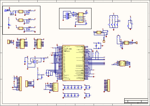
1122334455667788DDCCBBAATitle N umberR evisionS iz e A 2D ate:2010-7-28S heet of F ile:E:\Protel F iles\..\TM S 320F 2809.S chD ocD raw n B y:G PIO12/TZ1/C AN TX B /S PIS IM OB1V S S 2V DD IO3G PIO29/S C ITXD A/TZ64G PIO33/S C LA /EPW M S Y NC O/AD C S OC B O 5G PIO30/C AN R X A 6G PIO31/C AN TX A7G PIO14/TZ3/S C ITXD B /S PIC LK B 8G PIO15/TZ4/S C IR XD B /S PIS TEB 9V DD 10V S S11V DD 1A1812V S S 1AG NG 13V S S A214V DD A215A DC IN A716A DC IN A617A DC IN A518A DC IN A419A DC IN A320A DC IN A221A DC IN A122A DC IN A023A DC L O 24V S S AIO 25V DD AIO 26A DC IN B 027A DC IN B 128A DC IN B 229A DC IN B 330A DC IN B 431A DC IN B 532A DC IN B 633A DC IN B 734A DC R EF IN 35A DC R EF M 36A DC R EF P 37A DC R ES EX T 38V S S 2AG ND 39V DD 2A1840V S S 41V DD 42G PIO3443G PIO1/EPW M 1B /S PIS IM O D 44G PIO2/EPW M 2A 45V DD IO46G PIO0/EPW M 1A47G PIO3/EPW M 2B /S PIS OM ID 48V S S49G PIO16/S PIS IM O A/C AN TX B /T Z550G PIO4/EPW M 3A51G PIO17/S PIS OM IA/C AN R X B /T Z652G PIO5/EPW M 3B /S PIC LK D/EC A P153G PIO18/S PIC LK A/S C ITXD B 54V S S55G PIO6/EPW M 4A/EPW M S Y NC I/EPW M S YN C O56G PIO19/S PIS TEA /S C IR X DB57G PIO7/EPW M 4B /S PIS TED /EC AP258V DD59G PIO8/EPW M 5A/C A NTX B /AD C S OC AO60G PIO9/EPW M 5B /S C ITXD B /EC A P361V S S62G PIO20/EQE P1A/S PIS IM O C /C AN TX B63G PIO10/EPW M 6A/C A NR X B /AD C S OC B O 64V DD IO65X C LK OU T 66G PIO21/EQE P1B /S PIS OM IC /C AN R XB67V DD68V S S 69G PIO11/EPW M 6B /S C IR XD B /EC A P470G PIO22/EQE P1S /S PIC LKC /S C ITX DB 71G PIO23/EQE P1I/S PIS TE C /S C IR XD B 72TD I73TM S 74TC K 75TD O 76V S S 77X R S 78G PIO27/EC A P4/E QEP2S /S PIS TE B79EM U 080EM U 181V DD IO 82G PIO24/EC A P1/E QEP2A/S PIS IM O B83G PIO25/EC A P2/E QEP2B /S PIS O M IB91TR S T84V DD 85X 286V S S 87X 188V S S 89X C LK IN90G PIO28/S C IR XD A/TZ592V DD93V S S 94G PIO13/TZ2/C AN R X B /S PIS O M IB95V DD 3VF L96TE S T197TE S T298G PIO26/EC A P3/E QEP2I/S PIC LK B99G PIO32/S DA A/EPW M S YN C I/A DC S OC A O100U 1TM S 320F 2809PZ A1220MY 124pFC 1724pF C 18G NDX 1X 2X 1X 2123J1PW R 2.5G ND47uFC 1G ND1V out 2V in3TA B4U 2S PX 1117M 3-L -5-0G ND G NDV C C0.1uF C 3100uFC 2G ND1V out2V in3TA B 4U 3S PX 1117M 3-L -3-3V C CV DD 3.30.1uFC 5100uFC 4V DD 1.80.1uFC 7100uFC 6G NDG NDG ND1V out 2V in 3TA B4U 4S PX 1117M 3-L -1-8V C CR 1R 2R 31KR 5D 1LE D2V C CG NDA VD D3.3A VD D1.8A GN DA VC CR 412345P1EN C O DERO E11A 12A 24A 36A 48Y 412Y 314Y 216Y 118Y 83Y 75Y 67Y 59G ND10A 511A 613A 715A 817O E219V C C 20U 5S N 74HC 244D WO E19T/R1A 13B 117A 24B 216A 35B 315A 46B 414A 57B 513A 68B 612A 79B 711A 02B 018V C C 20G ND10U 8S N 74HC 245D WQ EPIQ EPI Q EPBQ EPB Q EPA Q EPA C A NR XO G NDV C CG NDG NDV DD 3.3CA NR X Q EP1I Q EP1A Q EP1B R S R /W LC M E NC A NT X C A NT XO LE N LR /W LR S G NDV DD 3.3R /W D 0D 1D 2D 3D 4D 5D 6D 7G NDD B 0D B 1D B 2D B 3D B 4D B 5D B 6D B 7TX D1G ND 2V C C 3R X D4V ref5C A NL 6C A NH 7R s8U 10PC A82C 250V C C20KR 2120KR 23G NDG NDV C C1122P6C A N_B US0.1uFC 20V C CV DD 3.310KR 1710KR 1810KR 2010KR 22K EY1K EY2K EY3K EY4G NDK E Y I N TN W O LS C LS D A V C C10KR 251KR 24R S T 1G NDX R S47uFC 211310118129147C 1+1C 2+4G ND15C 1-3V C C 16C 2-5V -6V +2U 6M AX 3232ES E1234567891110J3D C onnector 9G NDTX R XTXS C IR X D S C ITX D R XG NDV C C0.1uF C 130.1uF C 140.1uFC 160.1uFC 154.7KR 15 4.7KR 162.2KR 14V DD 3.3G NDX TR S TnEM U 0EM U 1X TDO X TC K X TM S X TDIX TR S Tn EM U 1G NDX TM S X TDI V DD 3.3X TDO EM U 033R 19X TC KTM S 1TD I 3TR S T2G ND 4PD (VD DIO)5N C6TD O 7G ND 8TC K_R E T 9G ND10TC K 11G ND 12EM U 013EM U 114J4JTA G HEA DE R1234567891011121314151617181920P2LC D10K R 6V C C G ND200R 7V C CG NDV OLR S LR /W LE ND 0D 1D 2D 3D 4D 5D 6D 7LE D+N R S T G ND V C CD AT29D AT3/C S1C MD /D I2V S S 3V DD4C L K/S C K 5V S S6D AT0/DO7D AT1/IR Q 8C A R D _IN S ER T 10G ND 11G NDJ2S DS TE B S IM OB C L KB S O M IB G NDV DD 3.310KR 11N IN TG NDV DD 3.310KR 8G ND85234671U 7O P07C SV C C30KV R 10.1uFC 100.1uFC 8A GN DG NDA DR E F IN V DD 3.31KR 910KR 10G ND0.1uFC 9A DINB 7S 1S W -DPDTA DINA 0A DINA 1A DINA 2A DINA 3A DINA 4A DINA 5A DINA 6A DINA 7A DINB 0A DINB 1A DINB 2A DINB 3A DINB 4A DINB 5A DINB 6A DINB 7A DR E F IN2.2uF C 122.2uF C 112.2KR 1200R 13A VD D3.3A GN DPW M 1A 12345678P3M OT ORV DD 3.3G NDPW M 1A PW M 1BPW M 2A PW M 2B PW M 2A PW M 1B PW M 2B D B 0D B 1D B 2D B 3D B 4D B 5D B 6D B 7R SR /W N W OL K EYIN TS IM OA S O M IAC L KA S TE A Q EP1A Q EP1B LC M E N Q EP1I S IM OB S O M IB C L KBS TE B S C IR X D S C ITX DC A NR X C A NT X S C LS D AV out1G ND 2V DD 3S D A4S C L 5A 06U 9D AC 7571G NDV C CS D AS C L0.1uFC 1912P4N IN T X R S C L KO UT V DD 1.8G ND 0.1uFC 42_P V DD 3.3G ND0.1uFC 3_P 0.1uFC 10_P A VD D1.8A GN D 0.1uF C 12_P 0.1uF C 15_P 0.1uF C 40_P 0.1uFC 46_P G NDG NDV DD 1.80.1uFC 59_P 0.1uFC 68_P 0.1uFC 85_P 0.1uFC 93_P 0.1uFC 96_P A GN DV DD 3.3G NDV DD 1.8A VD D1.8V DD 3.30.1uFC 65_P 0.1uFC 82_P A VD D3.3A GN D0.1uFC 26_P TP TP_VrefTPTP_5TPTP_1.8TPTP_3.3A GN DA DINA 0A DINA 1A DINA 2A DINA 3A DINA 4A DINA 5A DINA 6A DINA 7A DINB 0A DINB 1A DINB 2A DINB 3A DINB 4A DINB 5A DINB 6A DINB 71234567891011121314151617P5H eader 17C A NT XO C A NR XO。
TMS320f280x 数据手册NEW
TMS320F2809, TMS320F2808, TMS320F2806, TMS320F2802, TMS320F2801TMS320C2802, TMS320C2801,and TMS320F2801x DSPs数据手册著作编号:SPRS230J2003年-2007年9月修正除非有其他说明,本文档中包含了自发布日起的产品数据信息。
同时,产品也与德州仪器的每期标准规范说明书一致。
对产品的处理不包括所有参数的测试。
目录修订历史1 F280x,C2801x,C280x DSPs1.1特点1.2商标2 介绍2.1 引脚分配2.2 信号描述3 功能概况3.1 内存映射3.2 简单描述3.2.1 C28X CPU3.2.2 存储器总线(哈佛总线结构)3.2.3 外设总线3.2.4 实时JTAG接口和分析3.2.5 FLASH存储器3.2.6 ROM存储器3.2.7 M0,M1 SARAMs3.2.8 L0,L1,H0 SARAMs3.2.9 BOOT ROM3.2.10 安全性3.2.11 外设中断扩展(PIE)模块3.2.12 外部中断(XINT1,XINT2,XNMI)3.2.13 振荡器和锁相环(PLL)电路3.2.14 看门狗3.2.15 外部时钟3.2.16 低功耗模式3.2.17 外设框架3.2.18 通用输入输出(GPIO)复用引脚3.2.19 32位CPU定时器(0,1,2)3.2.20 控制外设3.2.21 串口外设3.3 寄存器映射3.4 器件仿真寄存器3.5 中断3.5.1 外部中断3.6 系统控制3.6.1 OSC和PLL模块3.6.2 看门狗模块3.7 低功耗模式模块4 外设4.1 32位CPU定时器0/1/24.2 增强型PWM模块(ePWM1/2/3/4/5/6)4.3 高精度PWM(HRPWM)4.4 增强型CAP模块(eCAP1/2/3/4)4.6 增强型AD转换模块4.6.1 ADC不用时引脚连接4.6.2 ADC寄存器4.7 增强型CAN模块(e-CAN-A和eCAN-B)4.8 SCI模组(SCI-A,SCI-B)4.9 SPI模组(SPI-A,SPI-B,SPI-C,SPI-D)4.10 I2C总线4.11 GPIO复用引脚5 器件支持5.1 器件和开发工具名称5.2 文档支持6 电路规范6.1 绝对最大额定值6.2 推荐运行条件6.3 电气特性6.4 电流消耗6.4.1 减小电流消耗6.4.2 电流消耗图表6.5 DSP无信号缓冲区时的引脚冲突连接6.6 时序参数模型6.6.1 时序参数的一般注意事项6.6.2 测试负荷电路6.7 时钟要求和特性6.8 上电时序6.8.1 电源管理和监控电路解决方案6.9 通用输入输出(GPIO)多路复用器6.9.1 GPIO-输出时序6.9.2 GPIO-输入时序6.10 增强型控制外设6.10.1 增强型脉宽调制(ePWM)时序6.10.2 Trip-Zone 输入时序6.10.3 外部中断时序6.10.4 I2C电路特性和时序6.10.5 串行外设接口(SPI)主动模式时序6.10.6串行外设接口(SPI)被动模式时序6.10.7 片上模-数转换器6.10.7.1 ADC上电控制位时序6.11 详细描述6.12 FLASH时序6.13 ROM时序(仅适用于C280x)7 从F280X到C280X的移植7.1 移植方法8 机械数据图形列表2-1 TMS320F2809,TMS320F2808 100-pin PZ LQFP(Top V iew)2-2 TMS320F2806 100-pin PZ LQFP(Top V iew)2-3 TMS320F2802,TMS320F2801,TMS320C2802,TMS320C2801,100-pin PZ LQFP(Top V iew)2-4 TMS320F2801x 100-Pin PZ LQFP(Top V iew)2-5 TMS320F2809,TMS320F2808,TMS320F2806,TMS320F2802,TMS320F2801,TMS320F28016,TMS320F28015,TMS320C2802,TMS320C2801 100-ball GGM and ZGM MicroStar BGA(Bottom View) 3-1 原理框图3-2 F2809内存映射3-3 F2808内存映射3-4 F2806内存映射3-5 F2802,C2802内存映射3-6 F2801, F28015,F28016,C2801内存映射3-7 外设中断资源3-8 使用外设中断模块时的中断复用3-9 时钟和复位电路3-10 OSC和PLL 方块图3-11 3.3V外部晶振的使用3-12 1.8V外部晶振的使用3-13 内部晶振的使用3-14 看门狗模块4-1 CPU定时器4-2 CPU定时器中断信号和输出信号4-3 280x系统的多路PWM模块4-4 ePWM4-5 eCAP功能方块图4-6 eQEP功能方块图4-7 ADC模块方块图4-8 使用内部参考时的ADC引脚连接4-9使用外部参考时的ADC引脚连接4-10 eCAN方块图和接口电路4-11 Ecan-A存储映射4-12 Ecan-B存储映射4-13 串行通信接口模组方块图4-14 SPI模组方块图(被动模式)4-15 I2C接口设计4-16 GPIO复用引脚方块图4-17 使用取样窗口的条件5-1 TMS320X280X器件命名举例6-1 典型的运行电流相对频率(F2808)6-2 典型的运行电流相对频率(F2808)6-3 无信号缓冲时的硬件连接6-4 3.3V测试负荷电路6-5 时钟时序6-7 热复位6-8 有效写入PLLCR寄存器的举例6-9 通用输出时序6-10 采样模式6-11 通用输入时序6-12 空闲进入和退出时序6-13 备用进入和退出时序6-14 使用通用IO口的中断唤醒6-15 PWM HI-Z特性6-16 ADCSOCAO or ADCSOCBO 时序6-17 外部中断时序6-18 SPI主动模式外部时序(CLOCK PHASE = 0)6-19 SPI主动模式外部时序(CLOCK PHASE = 1)6-20 SPI被动模式外部时序(CLOCK PHASE = 0)6-21 SPI被动模式外部时序(CLOCK PHASE = 1)6-22 ADC上电控制位时序6-23 ADC 模拟输入阻抗模式6-24 单通道模式时序6-25多通道模式时序表单列表2-1 硬件特性(100MHZ器件)2-2 硬件特性(60MHZ器件)2-3 信号描述3-1 F2809的FLASH段地址3-2 F2808的FLASH段地址3-3 F2802、F2806的FLASH段地址3-4 F2801、F28015、F28016的FLASH段地址3-5 使用代码保护模式的影响3-6 等待状态3-7 自举模式选择3-8 外部frame0寄存器3-9 外部frame1寄存器3-10 外部frame2寄存器3-11 器件硬件寄存器3-12 PIE外部中断3-13 PIE配置和控制寄存器3-14 外部中断寄存器3-15 PLL,Clocking,Watchdog,and Low-Power Mode 寄存器3-16 PLLCR寄存器位定义3-17 可能的PLL配置模式3-18 低功耗模式4-1 CPU定时器0,1,2配置和控制寄存器4-2 ePWM控制和标准寄存器4-4 eQEP控制和标准寄存器4-5 ADC寄存器4-6 3.3V eCAN收发器4-7 CAN寄存器MAP4-8 SCI-A寄存器4-9 SCI-B寄存器4-10 SPI-A寄存器4-11 SPI-B寄存器4-12 SPI-C寄存器4-13 SPI-D寄存器4-14 SPI-C寄存器4-15 GPIO寄存器4-16 F2808 GPIO复用表6-1 系统时钟为100MHZ时TMS320F2809,TMS320F2808的电流消耗6-2系统时钟为100MHZ时TMS320F2806的电流消耗6-3系统时钟为100MHZ时TMS320F2802,TMS320F2801的电流消耗6-4系统时钟为100MHZ时TMS320C2802,TMS320C2801的电流消耗6-5各种外设的典型电流消耗(100MHZ时)6-6 TMS320x280x时钟表和命名(100MHZ器件)6-7 TMS320x280x时钟表和命名(60MHZ器件)6-8 输入时钟频率6-9 XCLKIN时序要求-PLL enabled6-10 XCLKIN时序要求-PLL disabled6-11 XCLKOUT 开关特性(PLL bypassed or enabled)6-12 电源管理和监控电路解决方案6-13 Reset(XRS)时序要求6-14 通用输出开关特性6-15 通用输入时序要求6-16 IDLE模式时序要求6-17 IDLE模式开关特性6-18 STANDBY模式时序要求6-19 STANDBY模式开关特性6-20 HALT模式时序要求6-21 HALT模式开关特性6-22 ePWM时序要求6-23 ePWM开关特性6-24 Trip-Zone 输入时序要求6-25 高精度PWM特性(SYSCLKOUT=(60~100MHZ)6-26 eCAP时序要求6-27 eCAP开关特性6-28 eQEP时序要求6-29 eQEP开关特性6-30 外部ADC启动转换开关特性6-31 外部中断时序要求6-32 外部重点开关特性6-34 SPI主动模式外部时序(Clock Phase=0)6-35 SPI主动模式外部时序(Clock Phase=1)6-36 SPI被动模式外部时序(Clock Phase=0)6-37 SPI被动模式外部时序(Clock Phase=0)6-38 ADC电器特性(通过推荐运行条件验证)6-39 ADC上电延时6-40 不同ADC配置时的电流消耗(ADCCLK=12.5MHZ)6-41 单通道模式时序6-42 多通道模式时序6-43 Flash耐性6-44 SYSCLKOUT=100MHZ时的Flash参数6-45 Flash/OTP进入时序6-46 不同频率时的最大最小要求Flash/OTP等待状态6-47 ROM/OTP进入时序6-48不同频率时的最大最小要求ROM/OTP等待状态8-1 F280x Thermal Model 100-pin GGM Results8-2 F280x Thermal Model 100-pin PZ Results8-3 C280x Thermal Model 100-pin GGM Results8-4 C280x Thermal Model 100-pin PZ Results8-5 F2809 Thermal Model 100-pin GGM Results8-6 F2809 Thermal Model 100-pin PZ Results版本历史注意:早期版本的页码可能和当前版本页码有所不同该数据手册自SPRS230I到SPRS230J修正该文档因保证技术的准确性,已经被再次审阅。
MEMORY存储芯片TMS320F28035PNS中文规格书

6TMS320C6745,TMS320C6747SPRS377F –SEPTEMBER 2008–REVISED JUNE 2014Submit Documentation FeedbackProduct Folder Links:TMS320C6745TMS320C6747Revision History Copyright ©2008–2014,Texas Instruments Incorporated2Revision HistoryNOTE:Page numbers for previous revisions may differ from page numbers in the current version.This data manual revision history highlights the changes made to the SPRS377E device-specific data manual to make it an SPRS377F revision.Scope:Applicable updates to the TMS320C6747/C6745Fixed-and Floating-Point Digital Signal Processor device family,specifically relating to the TMS320C6747and TMS320C6745devices,which are all now in the production data (PD)stage of development,have been incorporated.Revision HistorySEEADDITIONS/MODIFICATIONS/DELETIONS Global•Turned on Navigation Icons on top of first page.•Updated Features,Applications,and Description for consistency and translation.•Moved Trademarks information from first page to within Section 7,Device and Documentation Support.•Moved ESDS Warning to within Section 7,Device and Documentation Support.Section 1.1FeaturesDeleted Highlights rmation was duplicated elsewhere in Features.Section 1.2ApplicationsAdded NEW section.Section 1.3DescriptionAdded NEW Device Information Table.Section 3.3.2.3C674x CPUTable 3-2,C674x Cache Registers:•Updated/Changed REGISTER DESCRIPTION for BYTE ADDRESSES 0000,0020,and 0040from "...See the System reference Guide..."to "See the Technical Reference Manual..."Section 3.6Terminal Functions Table 3-21,Universal Serial Bus (USB)Terminal Functions:•Updated/Changed USB0_VDDA12DESCRIPTION from "...must always be connected via a 1μFcapacitor..."to "...is recommended to be connected via a 0.22-μF capacitor..."Section 3.6.11Universal Asynchronous Receiver/Transmitter s (UART0,UART1,UART2)Table 3-16,Universal Asynchronous Receiver/Transmitter (UART)Terminal Functions:•Updated/Changed footnote from "...DSP Reference Guide -Literature Number SPRUFK4..."to "...DSP Technical Reference Manual (SPRUH91)..."Section 3.6.21Reserved and NoConnectTable 3-26,Reserved and No Connect Terminal Functions:•Updated/Changed RSV4DESCRIPTION from "...This pin may be tied high or low."to "...For proper device operation,this pin must be tied low or to CVDD."Section 3.6.23Unused USB0(USB2.0)and USB1(USB1.1)PinConfigurationsMoved to within Section 3.6,Terminal Functions Table 3-28,Unused USB0and USB1Pin Configurations:•Updated/Changed USB0_VDDA12Configuration by combining both Configuration columns and changing text to "Internal USB0PHY output connected to an external..."Section 5Device OperatingConditionsSection 5.2,Handling Ratings:•Split handling,ratings,and certifications from the Abs Max table and placed in NEW Handling Ratings table.Section 5.4Notes onRecommendedPower-On Hours(POH)Table 5-1,Recommended Power-On Hours:•Added Silicon Revision column.Section 6.10.6EMIFA ElectricalData/Timing Table 6-22,EMIFA Asynchronous Memory Switching Characteristics:•Updated/Changed the MIN,NOM,and MAX equations for NO.3,10,15,and 24from "...(EWC*16)..."to "...EWC..."Section 5.3,Recommended Operating Conditions:•Added "Unless specifically indicated"to "These I/O specifications apply to ..."footnote8TMS320C6745,TMS320C6747SPRS377F –SEPTEMBER 2008–REVISED JUNE 2014Submit Documentation FeedbackProduct Folder Links:TMS320C6745TMS320C6747Device Overview Copyright ©2008–2014,Texas Instruments Incorporated3Device Overview3.1Device CharacteristicsTable 3-1provides an overview of the C6745/6747low power digital signal processor.The table shows significant features of the device,including the capacity of on-chip RAM,peripherals,and the package type with pin count.Table 3-1.Characteristics of the C6745/C6747ProcessorHARDWARE FEATURESC6745C6747PeripheralsNot all peripherals pinsare available at the same time (for moredetail,see the Device Configurations section).EMIFB16bit,up to 128MB SDRAM 16/32bit,up to 256MB SDRAM EMIFAAsynchronous (8-bit bus width)RAM,Flash,NOR,NAND Asynchronous (8/16-bit bus width)RAM,Flash,16bit up to 128MB SDRAM,NOR,NAND Flash Card InterfaceMMC and SD cards supported.EDMA332independent channels,8QDMA channels,2Transfer controllers Timers264-Bit General Purpose (each configurable as 2separate 32-bit timers,1configurable as Watch Dog)UART3(one with RTS and CTS flow control)SPI2(each with one hardware chip select)I 2C2(both Master/Slave)Multichannel AudioSerial Port [McASP]2(each with transmit/receive,FIFO buffer,16/9serializers)3(each with transmit/receive,FIFO buffer,16/9serializers)10/100Ethernet MAC with Management Data I/O 1(RMII Interface)eHRPWM 6Single Edge,6Dual Edge Symmetric,or 3Dual Edge Asymmetric Outputs eCAP 332-bit capture inputs or 332-bit auxiliary PWM outputs eQEP232-bit QEP channels with 4inputs/channel UHPI-1(16-bit multiplexed address/data)USB 2.0(USB0)Full Speed Host Or Device with On-Chip PHY High-Speed OTG Controller with on-chip OTG PHY USB 1.1(USB1)-Full-Speed OHCI (as host)with on-chip PHY General-PurposeInput/Output Port8banks of 16-bit LCD Controller-1RTC-1(32KHz oscillator and seperate power trail.Provides time and date tracking and alarm capability.)PRU Subsystem(PRUSS)2Programmable PRU Cores On-Chip Memory Size (Bytes)320KB RAM 448KB RAMOrganization DSP 32KB L1Program (L1P)/Cache (up to 32KB)32KB L1Data (L1D)/Cache (up to 32KB)256KB Unified Mapped RAM/Cache (L2)DSP Memories can be made accessible to EDMA3,and other peripherals.-ADDITIONAL MEMORY128KB RAMC674x CPU ID +CPU Rev ID Control Status Register (CSR.[31:16])0x1400C674x MegamoduleRevision Revision ID Register (MM_REVID[15:0])0x0000。
tms320f28335中文数据手册介绍

常见DSP芯片的主频介绍

TMS320VC54xx:最高主频160MHz。
TMS320VC55xx:最高主频300MHz。
4)TMS320C6000系列:
TMS320C62xx:最高主频300MHz。
TMS320C67xx:最高主频230MHz。
TMS320C64xx:最高主频720MHz。
DSP可以降频使用吗?
可以,DSP的主频均有一定的工作范围,因此DSP均可以降频使用
TMS320LF24xxA-最高主频40MHz。
TMS320LF28xx-最高主频150MHz。
2)TMS320C3x系列:
TMS320C30:最高主频25MHz。
TMS320C31PQL80:最高主频40MHz。
TMS320C32PCM60:最高主频30MHz。
TMS320VC33PGE150:最高主频75MHz。
目录
常见DSP芯片的主频介绍
TI的DSP最高主频可以从芯片的型号中获得,但每一个系列不一定相同。
1)TMS320C2000系列:
TMS320F206-最高主频20MHz。
TMS320C203/C206-最高主频40MHz。
TMS320F24x-最Байду номын сангаас主频20MHz。
TMS320LF24xx-最高主频30MHz。
常见DSP芯片的主频介绍
作者:发布时间:2011-06-23文章来源:指数网用户
TAG:
--------------------------------------------------------------------------------
TMS320F2812中文手册

TMS320F2812中文手册第1章芯片结构及性能概述TMS320C2000系列是美国TI公司推出的最佳测控应用的定点DSP芯片,其主流产品分为四个系列:C20x、C24x、C27x和C28x。
C20x可用于通信设备、数字相机、嵌入式家电设备等;C24x主要用于数字马达控制、电机控制、工业自动化、电力转换系统等。
近年来,TI公司又推出了具有更高性能的改进型C27x和C28x系列芯片,进一步增强了芯片的接口能力和嵌入功能,从而拓宽了数字信号处理器的应用领域。
TMS320C28x系列是TI公司最新推出的DSP芯片,是目前国际市场上最先进、功能最强大的32位定点DSP芯片。
它既具有数字信号处理能力,又具有强大的事件管理能力和嵌入式控制功能,特别适用于有大批量数据处理的测控场合,如工业自动化控制、电力电子技术应用、智能化仪器仪表及电机、马达伺服控制系统等。
本章将介绍TMS320C28x系列芯片的结构、性能及特点,并给出该系列芯片的引脚分布及引脚功能。
1.1 TMS320C28x 系列芯片的结构及性能C28x系列的主要片种为TMS320F2810和TMS320F2812。
两种芯片的差别是:F2812内含128K×16位的片内Flash存储器,有外部存储器接口,而F2810仅有64K×16位的片内Flash存储器,且无外部存储器接口。
其硬件特征如表1-1所示。
表1-1 硬件特征特征 F2810 F2812 指令周期(150MHz) 6.67ns 6.67ns SRAM(16位/字)18K 18K 3.3V片内Flash(16位/字) 64K 128K 片内Flash/SRAM的密钥有有有有 Boot ROM掩膜ROM 有有外部存储器接口无有事件管理器A和B(EVA和EVB)EVA、EVB EVA、EVB*通用定时器 4 4*比较寄存器/脉宽调制 16 16*捕获/正交解码脉冲电路 6/2 6/2 看门狗定时器有有 12位的ADC 有有*通道数 16 16TMS320C28x系列DSP的CPU与外设(上) ?2?续表特征 F2810 F2812 32位的CPU定时器 3 3 串行外围接口有有串行通信接口(SCI)A和B SCIA、SCIB SCIA、SCIB 控制器局域网络有有多通道缓冲串行接口有有数字输入/输出引脚(共享)有有外部中断源 3 3 核心电压1.8V 核心电压1.8V 供电电压 I/O电压3.3V I/O电压3.3V 封装128针PBK 179针GHH,176针PGF 温度选择‡ A:-40? ~ +85? PGF和GHH PBK S:-40? ~ +125? 仅适用于TMS 仅适用于TMS 产品状况‡‡产品预览(PP) AI AI 高级信息(AI)(TMP)‡‡‡ (TMP)‡‡‡ 产品数据(PD)注:‡ “S”是温度选择(-40? ~ +125?)的特征化数据,仅对TMS是适用的。
西门子 NXGPro+ 控制系统手册_操作手册说明书
3.4
单元通讯的协议 ............................................................................................................ 36
3.5
NXGpro+ 高级安全 .......................................................................................................37
3.2
功率拓扑 ......................................................................................................................34
3.3
控制系统概述 ...............................................................................................................35
NXGPro+ 控制系统手册
NXGPro+ 控制系统手册
操作手册
AC
A5E50491925J
安全性信息
1
安全注意事项
2
控制系统简介
3
NXGPro+ 控制系统简介
4
硬件用户界面说明
5
参数配置/地址
6
运行控制系统
7
高级的操作功能
8
软件用户界面
9
运行软件
10
故障和报警检修
11
合肥工业大学科技成果——智能体感平衡车驱动控制系统
合肥工业大学科技成果——智能体感平衡车驱动控制系统所属领域电子信息成果简介智能体感平衡车控制系统是用于独轮车、双轮车、带扶手车、滑板车等各类智能体感车的驱动控制系统,包括硬件系统和软件系统。
智能体感平衡车领域,从2014年开始兴起,2015年逐步推广,2016年有望更加普及。
其主要功能是为各类体感车提供安全、稳定的控制。
选用合适的主处理器,通过加速度计和陀螺仪进行测量数据和处理数据,进而精确判断车辆倾角,运用最优的控制算法控制电机,进而驱动控制器,实现对智能体感车快速、安全、稳定的驱动控制,同时加入安全保护算法和安全装置,提高安全、可靠性。
2015年,已经完成了主控芯片,电机、驱动器、传感器等的选型,有了数据融合技术和驱动器控制技术等方面的成熟技术积累,并已开发出性能较为稳定的驱动控制板。
应用创新1、控制板主处理器采用功能强大和可扩展性强的TIMS320F2809DSP,驱动芯片采用集成型三相无刷电机前置驱动器DRV8301,实现直流无刷电机的电流、速度和位置的闭环控制,且控制稳定可靠。
2、驱动控制器的软件算法上加入各类安全保护算法,并在硬件板上集成了温度报警、安全闪烁灯等安全装置,大大提高了控制器的安全可靠性、通用性。
3、实现了使用手机APP进行体感车的运动模式、灯光、音乐等的控制及电流、温度等信息的监控。
4、软件程序系统构架清晰、完整,预留丰富功能接口,便于开发应用到各类体感系统。
技术创新1、加速度计与陀螺仪数据融合处理技术将二者信号进行融合使测得的倾角更准确。
2、系统采用三内阻采样技术采集电流信号,无需使用电流传感器,性价比高,启动和运行全程FOC控制。
3、基于霍尔传感器实现无编码器位置控制,适用于一般对成本要求较高的场合。
4、系统已实现不采用硬件开关,通过采集倾角、电流、轮速等信息实现“体感开关”,经济、安全、环保。
5、系统具有软启动功能,即启动时适应人体重心,平稳过渡到体感功能,体验舒适。
半导体传感器TMS320F2808PZA中文规格书

TMS320F2810, TMS320F2810-Q1, TMS320F2811, TMS320F2811-Q1TMS320F2812, TMS320F2812-Q1SPRS174V – APRIL 2001 – REVISED FEBRUARY 2021Copyright © 2021 Texas Instruments Incorporated Submit Document Feedback17 Product Folder Links: TMS320F2810TMS320F2810-Q1TMS320F2811TMS320F2811-Q1TMS320F2812TMS320F2812-Q1TMS320F2810, TMS320F2810-Q1, TMS320F2811, TMS320F2811-Q1TMS320F2812, TMS320F2812-Q1SPRS174V – APRIL 2001 – REVISED FEBRUARY 20218.9 Thermal Resistance Characteristics for 176-Pin PGF Package(1)These values are based on a JEDEC defined 2S2P system (with the exception of the Theta JC [RΘJC] value, which is based on aJEDEC defined 1S0P system) and will change based on environment as well as application. For more information, see these EIA/JEDEC standards:•JESD51-2, Integrated Circuits Thermal Test Method Environmental Conditions - Natural Convection (Still Air)•JESD51-3, Low Effective Thermal Conductivity Test Board for Leaded Surface Mount Packages•JESD51-7, High Effective Thermal Conductivity Test Board for Leaded Surface Mount Packages•JESD51-9, Test Boards for Area Array Surface Mount Package Thermal Measurements8.10 Thermal Resistance Characteristics for 128-Pin PBK Package(1)These values are based on a JEDEC defined 2S2P system (with the exception of the Theta JC [RΘJC] value, which is based on aJEDEC defined 1S0P system) and will change based on environment as well as application. For more information, see these EIA/JEDEC standards:•JESD51-2, Integrated Circuits Thermal Test Method Environmental Conditions - Natural Convection (Still Air)•JESD51-3, Low Effective Thermal Conductivity Test Board for Leaded Surface Mount Packages•JESD51-7, High Effective Thermal Conductivity Test Board for Leaded Surface Mount Packages•JESD51-9, Test Boards for Area Array Surface Mount Package Thermal Measurements8.11 Thermal Design ConsiderationsBased on the end application design and operational profile, the I DD and I DDIO currents could vary. Systems that exceed the recommended maximum power dissipation in the end product may require additional thermal enhancements. Ambient temperature (T A) varies with the end application and product design. The critical factor that affects reliability and functionality is T J, the junction temperature, not the ambient temperature. Hence, care should be taken to keep T J within the specified limits. T case should be measured to estimate the operating junction temperature T J. T case is normally measured at the center of the package top-side surface. The thermal application report Semiconductor and IC Package Thermal Metrics helps to understand the thermal metrics and definitions.26Submit Document Feedback Copyright © 2021 Texas Instruments Incorporated Product Folder Links: TMS320F2810TMS320F2810-Q1TMS320F2811TMS320F2811-Q1TMS320F2812TMS320F2812-Q1。
TMS320F206PZA中文资料
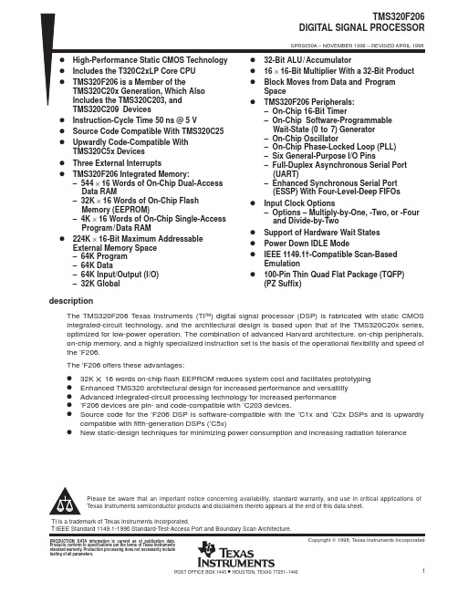
D D D D
D D D D D
32-Bit ALU / Accumulator 16 × 16-Bit Multiplier With a 32-Bit Product Block Moves from Data and Program Space TMS320F206 Peripherals: – On-Chip 16-Bit Timer – On-Chip Software-Programmable Wait-State (0 to 7) Generator – On-Chip Oscillator – On-Chip Phase-Locked Loop (PLL) – Six General-Purpose I/O Pins – Full-Duplex Asynchronous Serial Port (UART) – Enhanced Synchronous Serial Port (ESSP) With Four-Level-Deep FIFOs Input Clock Options – Options – Multiply-by-One, -Two, or -Four and Divide-by-Two Support of Hardware Wait States Power Down IDLE Mode IEEE 1149.1†-Compatible Scan-Based Emulation 100-Pin Thin Quad Flat Package (TQFP) (PZ Suffix)
2
POST OFFICE BOX 1443
TEST MP / MC DIV1 V CCP DIV 2 HOLDA V DD IO2 IO3 PLL5V V DD CLKIN/X2 X1 VSS CLKOUT1 V CCP NMI HOLD / INT1 INT2 INT3 VSS D0 D1 D2 VSS
TMS320F2808开发板硬件手册2

TMS320F2808开发板用户手册(Ver1.2)1产品简介21产品照片TMS320F2808增强版是一套基于 TMS320F2808DSP的学习开发平台,既可作为开发板供用户学习使用,也可作为系统板嵌入到用户的产品供用户进行二次开发以便缩短产品开发周期。
1.2开发板特性1USB接口多功能调试器不要求用户电脑具有并口和串口;支持程序的下载与在线仿真;支持虚拟 UART串行通信;2)多种仿真模式自仿真:板载仿真器仿真开发板自身的 CPU;仿真它:板载仿真器仿真其它 DSP/DSC开发板;它仿真:自身的 CPU可以由其它仿真器来仿真,如 XDS510、XDS560等;3)系统资源1. DSP处理器 TMS320F2808,32位定点高速数字处理器,最高工作频率 100M 2.正交编码器接口3. 4个 LED灯4. 2个直流电机接口,工作电压 4.5-36V,最大驱动电流 1A5. 1路 CAN总线接口,可以直接应用于工业现场6. USB转 UART通信接口,方便与上位机实现通讯7.字符 LCD接口/图形 LCD接口8. 4个按键,方便用户配合 LCD实现人机对话9. 16路电压型 AD输入接口 (其中一路可以用电位器调节输入电压 )10. SD卡接口 (通过 SPI接口操作 SD卡、提供 FAT32程序代码 )11.板载 USB仿真器12. PWM语音输出电路(提供 PWM音乐播放实验代码) 13. DC5V外部电源输入接口4)代码及实验项目1.用户程序烧写实验(烧写后可脱机运行)2.正交编码器实验(位置读取、速度计算)3.跑马灯实验4.直流电机控制实验5. CAN总线收发实验6. SCI发送接收实验7. 1602字符 LCD显示实验8.键盘扫描实验9. SD卡读写实验 [注:SD卡自购 ]10.定时器等所有片内外设实验11. PWM音乐播放实验12. AD转换实验13.综合实验以上项目均提供 C语言版本的程序源代码,并有详细中文注释。
MEMORY存储芯片TMS320F28335PGFA中文规格书
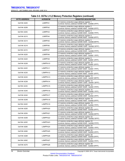
16TMS320C6745,TMS320C6747SPRS377F –SEPTEMBER 2008–REVISED JUNE 2014Submit Documentation FeedbackProduct Folder Links:TMS320C6745TMS320C6747Device OverviewCopyright ©2008–2014,Texas Instruments Incorporated Table 3-3.C674x L1/L2Memory Protection Registers (continued)BYTE ADDRESSACRONYM REGISTER DESCRIPTION 0x0184A204L2MPPA1L2memory protection page attribute register 1(controls memory address 0x00802000-0x00803FFF)0x0184A208L2MPPA2L2memory protection page attribute register 2(controls memory address 0x00804000-0x00805FFF)0x0184A20CL2MPPA3L2memory protection page attribute register 3(controls memory address 0x00806000-0x00807FFF)0x0184A210L2MPPA4L2memory protection page attribute register 4(controls memory address 0x00808000-0x00809FFF)0x0184A214L2MPPA5L2memory protection page attribute register 5(controls memory address 0x0080A000-0x0080BFFF)0x0184A218L2MPPA6L2memory protection page attribute register 6(controls memory address 0x0080C000-0x0080DFFF)0x0184A21CL2MPPA7L2memory protection page attribute register 7(controls memory address 0x0080E000-0x0080FFFF)0x0184A220L2MPPA8L2memory protection page attribute register 8(controls memory address 0x00810000-0x00811FFF)0x0184A224L2MPPA9L2memory protection page attribute register 9(controls memory address 0x00812000-0x00813FFF)0x0184A228L2MPPA10L2memory protection page attribute register 10(controls memory address 0x00814000-0x00815FFF)0x0184A22CL2MPPA11L2memory protection page attribute register 11(controls memory address 0x00816000-0x00817FFF)0x0184A230L2MPPA12L2memory protection page attribute register 12(controls memory address 0x00818000-0x00819FFF)0x0184A234L2MPPA13L2memory protection page attribute register 13(controls memory address 0x0081A000-0x0081BFFF)0x0184A238L2MPPA14L2memory protection page attribute register 14(controls memory address 0x0081C000-0x0081DFFF)0x0184A23CL2MPPA15L2memory protection page attribute register 15(controls memory address 0x0081E000-0x0081FFFF)0x0184A240L2MPPA16L2memory protection page attribute register 16(controls memory address 0x00820000-0x00821FFF)0x0184A244L2MPPA17L2memory protection page attribute register 17(controls memory address 0x00822000-0x00823FFF)0x0184A248L2MPPA18L2memory protection page attribute register 18(controls memory address 0x00824000-0x00825FFF)0x0184A24CL2MPPA19L2memory protection page attribute register 19(controls memory address 0x00826000-0x00827FFF)0x0184A250L2MPPA20L2memory protection page attribute register 20(controls memory address 0x00828000-0x00829FFF)0x0184A254L2MPPA21L2memory protection page attribute register 21(controls memory address 0x0082A000-0x0082BFFF)0x0184A258L2MPPA22L2memory protection page attribute register 22(controls memory address 0x0082C000-0x0082DFFF)0x0184A25CL2MPPA23L2memory protection page attribute register 23(controls memory address 0x0082E000-0x0082FFFF)0x0184A260L2MPPA24L2memory protection page attribute register 24(controls memory address 0x00830000-0x00831FFF)0x0184A264L2MPPA25L2memory protection page attribute register 25(controls memory address 0x00832000-0x00833FFF)0x0184A268L2MPPA26L2memory protection page attribute register 26(controls memory address 0x00834000-0x00835FFF)0x0184A26CL2MPPA27L2memory protection page attribute register 27(controls memory address 0x00836000-0x00837FFF)0x0184A270L2MPPA28L2memory protection page attribute register 28(controls memory address 0x00838000-0x00839FFF)。
tms320f28030引 读写

tms320f28030引读写一、概述TMS320F28030是一款基于TexasInstruments的TMS320C28x系列DSP芯片,广泛应用于工业控制、电机控制、音频处理等领域。
该芯片具有丰富的外设和接口,提供了强大的数据处理能力。
在使用TMS320F28030时,需要了解其引脚定义和读写操作方法,以便正确连接硬件和编写代码。
二、引脚说明TMS320F28030芯片共有40个引脚,分为电源、地、控制、输入输出、时钟等几个部分。
其中,需要特别关注以下引脚:1.外部存储器接口(EMIF)引脚:用于连接外部存储器,如SD 卡、RAM等。
2.通用输入输出(GPIO)引脚:用于连接外部设备或其他芯片的接口。
3.时钟(CLK)引脚:用于设置系统时钟。
三、读写操作TMS320F28030芯片的读写操作可以通过软件编程实现。
下面介绍一些常用的读写操作方法:1.读取寄存器值:可以通过访问芯片的寄存器地址,读取相应寄存器的值。
例如,要读取GPIO口的值,可以通过访问相应的寄存器地址来读取该口的状态。
2.写入寄存器值:可以将数据写入指定的寄存器地址,从而对芯片进行配置或控制。
例如,要设置GPIO口的输出模式,可以将相应的数据写入相应的寄存器地址。
3.读写内存:可以通过EMIF接口读写外部存储器的数据。
例如,要读取SD卡中的数据,需要先通过EMIF接口将SD卡与芯片连接,然后通过读写内存操作来读取数据。
四、注意事项在进行读写操作时,需要注意以下几点:1.正确设置时钟和时序,以确保读写操作的正确性和可靠性。
2.避免对正在使用的寄存器进行读写操作,以免造成系统崩溃或数据丢失。
3.在进行读写操作时,需要考虑到芯片的功耗和发热情况,以延长芯片的使用寿命。
五、总结本文介绍了TMS320F28030芯片的引脚说明和读写操作方法,希望能对使用该芯片的用户提供帮助。
在使用该芯片时,需要仔细阅读相关文档和资料,并按照正确的步骤进行操作,以确保系统的稳定性和可靠性。
MEMORY存储芯片TMS320F28032PAGT中文规格书
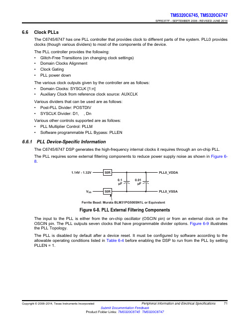
1.14V - 1.32V V SS PLL0_VDDAPLL0_VSSA 71TMS320C6745,TMS320C6747SPRS377F –SEPTEMBER 2008–REVISED JUNE 2014Submit Documentation FeedbackProduct Folder Links:TMS320C6745TMS320C6747Peripheral Information and Electrical SpecificationsCopyright ©2008–2014,Texas Instruments Incorporated 6.6Clock PLLsThe C6745/6747has one PLL controller that provides clock to different parts of the system.PLL0provides clocks (though various dividers)to most of the components of the device.The PLL controller provides the following:•Glitch-Free Transitions (on changing clock settings)•Domain Clocks Alignment•Clock Gating•PLL power downThe various clock outputs given by the controller are as follows:•Domain Clocks:SYSCLK [1:n]•Auxiliary Clock from reference clock source:AUXCLKVarious dividers that can be used are as follows:•Post-PLL Divider:POSTDIV•SYSCLK Divider:D1,¼,DnVarious other controls supported are as follows:•PLL Multiplier Control:PLLM•Software programmable PLL Bypass:PLLEN6.6.1PLL Device-Specific InformationThe C6745/6747DSP generates the high-frequency internal clocks it requires through an on-chip PLL.The PLL requires some external filtering components to reduce power supply noise as shown in Figure 6-8.Figure 6-8.PLL External Filtering ComponentsThe input to the PLL is either from the on-chip oscillator (OSCIN pin)or from an external clock on the OSCIN pin.The PLL outputs seven clocks that have programmable divider options.Figure 6-9illustrates the PLL Topology.The PLL is disabled by default after a device reset.It must be configured by software according to the allowable operating conditions listed in Table 6-4before enabling the DSP to run from the PLL by setting PLLEN =1.79TMS320C6745,TMS320C6747SPRS377F –SEPTEMBER 2008–REVISED JUNE 2014Submit Documentation FeedbackProduct Folder Links:TMS320C6745TMS320C6747Peripheral Information and Electrical SpecificationsCopyright ©2008–2014,Texas Instruments Incorporated 6.8General-Purpose Input/Output (GPIO)The GPIO peripheral provides general-purpose pins that can be configured as either inputs or outputs.When configured as an output,a write to an internal register can control the state driven on the output pin.When configured as an input,the state of the input is detectable by reading the state of an internal register.In addition,the GPIO peripheral can produce CPU interrupts and EDMA events in different interrupt/event generation modes.The GPIO peripheral provides generic connections to external devices.The GPIO pins are grouped into banks of 16pins per bank (i.e.,bank 0consists of GPIO [0:15]).The C6745/6747GPIO peripheral supports the following:•Up to 128Pins on ZKB and up to 109Pins on PTP package configurable as GPIO•External Interrupt and DMA request Capability–Every GPIO pin may be configured to generate an interrupt request on detection of rising and/or falling edges on the pin.–The interrupt requests within each bank are combined (logical or)to create eight unique bank level interrupt requests.–The bank level interrupt service routine may poll the INTSTATx register for its bank to determine which pin(s)have triggered the interrupt.–GPIO Banks 0,1,2,3,4,5,6,and 7Interrupts assigned to DSP Events 65,41,49,52,54,59,62and 72respectively–Additionally,GPIO Banks 0,1,2,3,4,and 5Interrupts assigned to EDMA events 6,7,22,23,28,and 29respectively.•Set/clear functionality:Firmware writes 1to corresponding bit position(s)to set or to clear GPIO signal(s).This allows multiple firmware processes to toggle GPIO output signals without critical section protection (disable interrupts,program GPIO,re-enable interrupts,to prevent context switching to anther process during GPIO programming).•Separate Input/Output registers•Output register in addition to set/clear so that,if preferred by firmware,some GPIO output signals can be toggled by direct write to the output register(s).•Output register,when read,reflects output drive status.This,in addition to the input register reflecting pin status and open-drain I/O cell,allows wired logic be implemented.The memory map for the GPIO registers is shown in Table 6-8.See the TMS320C6745/C6747DSP Peripherals Overview Reference Guide.(SPRUFK9)for more details.6.8.1GPIO Register Description(s)Table 6-8.GPIO RegistersBYTE ADDRESSACRONYM REGISTER DESCRIPTION 0x01E26000REV Peripheral Revision Register 0x01E26004-Reserved 0x01E26008BINTEN GPIO Interrupt Per-Bank Enable Register GPIO BANKS 0AND 10x01E26010DIR01GPIO Banks 0and 1Direction Register 0x01E26014OUT_DATA01GPIO Banks 0and 1Output Data Register 0x01E26018SET_DATA01GPIO Banks 0and 1Set Data Register 0x01E2601CCLR_DATA01GPIO Banks 0and 1Clear Data Register 0x01E26020IN_DATA01GPIO Banks 0and 1Input Data Register 0x01E26024SET_RIS_TRIG01GPIO Banks 0and 1Set Rising Edge Interrupt Register 0x01E26028CLR_RIS_TRIG01GPIO Banks 0and 1Clear Rising Edge Interrupt Register 0x01E2602CSET_FAL_TRIG01GPIO Banks 0and 1Set Falling Edge Interrupt Register 0x01E26030CLR_FAL_TRIG01GPIO Banks 0and 1Clear Falling Edge Interrupt Register。
由TMS320F2808组成的DSP最小系统硬件电路及扩展应用
由TMS320F2808组成的DSP最小系统硬件电路及扩
展应用
通过介绍了新一代美国德州仪器(TI)公司C2000平台上的定点DSP芯片TMS320F2808的性能特点和硬件结构、外设模块,给出了由TMS320F2808组成的DSP最小应用系统,并介绍了各部分电路的设计方案
TMS320F2808是德州仪器(TI)公司推出的C2000平台上的定点DSP芯片,具有低成本、低功耗和高性能处理能力,特别适用于大量数据处理的测控领域和复杂运算的电机控制领域。
本文在介绍TMS320F2808的性能基础上设计了以TMS320F2808 DSP为核心的最小应用系统,并给出了各部分具体硬件电路的设计和典型扩展应用。
1 TMS320F2808特点
TMS320F2808是美国TI公司推出的C2000平台上的32位定点DSP 芯片,具有低成本、低功耗和高性能处理能力,外设功能增强且极具价格优势,采用100引脚封装,所有产品引脚兼容,具有高达64 kB的闪存和100MIPS的性能。
片上集成了丰富而又先进的增强型外设,如16路PWM输出通道、6路HRPWM输出通道、4个eCAP输入接口、6个32位/16位定。
- 1、下载文档前请自行甄别文档内容的完整性,平台不提供额外的编辑、内容补充、找答案等附加服务。
- 2、"仅部分预览"的文档,不可在线预览部分如存在完整性等问题,可反馈申请退款(可完整预览的文档不适用该条件!)。
- 3、如文档侵犯您的权益,请联系客服反馈,我们会尽快为您处理(人工客服工作时间:9:00-18:30)。
TMS320F2809,TMS320F2808,TMS320F2806 TMS320F2802,TMS320F2801TMS320C2802,TMS320C2801,and TMS320F2801x DSPsData ManualLiterature Number:SPRS230JOctober2003–Revised September2007PRODUCTION DATA information is current as of publication date.Products conform to specifications per the terms of the TexasInstruments standard warranty.Production processing does notnecessarily include testing of all parameters.ContentsTMS320F2809,TMS320F2808,TMS320F2806TMS320F2802,TMS320F2801TMS320C2802,TMS320C2801,and TMS320F2801x DSPsSPRS230J–OCTOBER 2003–REVISED SEPTEMBER 2007Revision History ...........................................................................................................................91F280x,F2801x,C280x DSPs . (11)1.1Features .....................................................................................................................111.2Getting Started (122)Introduction (13)2.1Pin Assignments ............................................................................................................152.2Signal Descriptions (213)Functional Overview (27)3.1Memory Maps ...............................................................................................................283.2Brief Descriptions ...........................................................................................................363.2.1C28x CPU .......................................................................................................363.2.2Memory Bus (Harvard Bus Architecture)....................................................................363.2.3Peripheral Bus ..................................................................................................363.2.4Real-Time JTAG and Analysis ................................................................................363.2.5Flash ..............................................................................................................373.2.6ROM ...............................................................................................................373.2.7M0,M1SARAMs ...............................................................................................373.2.8L0,L1,H0SARAMs ............................................................................................373.2.9Boot ROM ........................................................................................................373.2.10Security ..........................................................................................................393.2.11Peripheral Interrupt Expansion (PIE)Block ..................................................................403.2.12External Interrupts (XINT1,XINT2,XNMI)...................................................................403.2.13Oscillator and PLL ..............................................................................................403.2.14Watchdog ........................................................................................................403.2.15Peripheral Clocking .............................................................................................403.2.16Low-Power Modes ..............................................................................................403.2.17Peripheral Frames 0,1,2(PFn)..............................................................................413.2.18General-Purpose Input/Output (GPIO)Multiplexer .........................................................413.2.1932-Bit CPU-Timers (0,1,2)...................................................................................413.2.20Control Peripherals .............................................................................................413.2.21Serial Port Peripherals .........................................................................................423.3Register Map ................................................................................................................423.4Device Emulation Registers ...............................................................................................443.5Interrupts ....................................................................................................................443.5.1External Interrupts ..............................................................................................473.6System Control .............................................................................................................483.6.1OSC and PLL Block ............................................................................................493.6.2Watchdog Block .................................................................................................523.7Low-Power Modes Block (534)Peripherals (54)4.132-Bit CPU-Timers 0/1/2..................................................................................................544.2Enhanced PWM Modules (ePWM1/2/3/4/5/6)..........................................................................564.3Hi-Resolution PWM (HRPWM)...........................................................................................584.4Enhanced CAP Modules (eCAP1/2/3/4)................................................................................584.5Enhanced QEP Modules (eQEP1/2).....................................................................................614.6Enhanced Analog-to-Digital Converter (ADC)Module ................................................................634.6.1ADC Connections if the ADC Is Not Used ...................................................................664.6.2ADC Registers ...................................................................................................674.7Enhanced Controller Area Network (eCAN)Modules (eCAN-A and eCAN-B).....................................684.8Serial Communications Interface (SCI)Modules (SCI-A,SCI-B)....................................................73Contents 2Submit Documentation FeedbackTMS320F2809,TMS320F2808,TMS320F2806TMS320F2802,TMS320F2801TMS320C2802,TMS320C2801,and TMS320F2801x DSPsSPRS230J–OCTOBER2003–REVISED SEPTEMBER20074.9Serial Peripheral Interface(SPI)Modules(SPI-A,SPI-B,SPI-C,SPI-D) (76)4.10Inter-Integrated Circuit(I2C) (80)4.11GPIO MUX (82)5Device Support (86)5.1Device and Development Support Tool Nomenclature (86)5.2Documentation Support (88)6Electrical Specifications (91)6.1Absolute Maximum Ratings (91)6.2Recommended Operating Conditions (92)6.3Electrical Characteristics (92)6.4Current Consumption (93)6.4.1Reducing Current Consumption (97)6.4.2Current Consumption Graphs (98)6.5Emulator Connection Without Signal Buffering for the DSP (99)6.6Timing Parameter Symbology (100)6.6.1General Notes on Timing Parameters (100)6.6.2Test Load Circuit (101)6.6.3Device Clock Table (101)6.7Clock Requirements and Characteristics (103)6.8Power Sequencing (104)6.8.1Power Management and Supervisory Circuit Solutions (104)6.9General-Purpose Input/Output(GPIO) (107)6.9.1GPIO-Output Timing (107)6.9.2GPIO-Input Timing (108)6.9.3Sampling Window Width for Input Signals (109)6.9.4Low-Power Mode Wakeup Timing (110)6.10Enhanced Control Peripherals (113)6.10.1Enhanced Pulse Width Modulator(ePWM)Timing (113)6.10.2Trip-Zone Input Timing (113)6.10.3External Interrupt Timing (115)6.10.4I2C Electrical Specification and Timing (116)6.10.5Serial Peripheral Interface(SPI)Master Mode Timing (116)6.10.6SPI Slave Mode Timing (120)6.10.7On-Chip Analog-to-Digital Converter (123)6.11Detailed Descriptions (128)6.12Flash Timing (129)6.13ROM Timing(C280x only) (130)7Migrating From F280x Devices to C280x Devices (131)7.1Migration Issues (131)8Mechanical Data (132)Contents3TMS320F2809,TMS320F2808,TMS320F2806TMS320F2802,TMS320F2801TMS320C2802,TMS320C2801,and TMS320F2801x DSPsSPRS230J–OCTOBER2003–REVISED SEPTEMBER2007List of Figures2-1TMS320F2809,TMS320F2808100-Pin PZ LQFP(Top View) (16)2-2TMS320F2806100-Pin PZ LQFP(Top View) (17)2-3TMS320F2802,TMS320F2801,TMS320C2802,TMS320C2801100-Pin PZ LQFP(Top View) (18)2-4TMS320F2801x100-Pin PZ LQFP(Top View) (19)2-5TMS320F2809,TMS320F2808,TMS320F2806,TMS320F2802,TMS320F2801,TMS320F28016,TMS320F28015,TMS320C2802,TMS320C2801100-Ball GGM and ZGM MicroStar BGA™(Bottom View) (20)3-1Functional Block Diagram (27)3-2F2809Memory Map (28)3-3F2808Memory Map (29)3-4F2806Memory Map (30)3-5F2802,C2802Memory Map (31)3-6F2801,F28015,F28016,C2801Memory Map (32)3-7External and PIE Interrupt Sources (45)3-8Multiplexing of Interrupts Using the PIE Block (46)3-9Clock and Reset Domains (48)3-10OSC and PLL Block Diagram (49)3-11Using a3.3-V External Oscillator (50)3-12Using a1.8-V External Oscillator (50)3-13Using the Internal Oscillator (50)3-14Watchdog Module (52)4-1CPU-Timers (54)4-2CPU-Timer Interrupt Signals and Output Signal (55)4-3Multiple PWM Modules in a280x System (56)4-4ePWM Sub-Modules Showing Critical Internal Signal Interconnections (58)4-5eCAP Functional Block Diagram (59)4-6eQEP Functional Block Diagram (61)4-7Block Diagram of the ADC Module (64)4-8ADC Pin Connections With Internal Reference (65)4-9ADC Pin Connections With External Reference (66)4-10eCAN Block Diagram and Interface Circuit (69)4-11eCAN-A Memory Map (70)4-12eCAN-B Memory Map (71)4-13Serial Communications Interface(SCI)Module Block Diagram (75)4-14SPI Module Block Diagram(Slave Mode) (79)4-15I2C Peripheral Module Interfaces (81)4-16GPIO MUX Block Diagram (82)4-17Qualification Using Sampling Window (85)5-1Example of TMS320x280x Device Nomenclature (87)4Submit Documentation Feedback List of FiguresTMS320F2809,TMS320F2808,TMS320F2806TMS320F2802,TMS320F2801TMS320C2802,TMS320C2801,and TMS320F2801x DSPsSPRS230J–OCTOBER2003–REVISED SEPTEMBER2007 6-1Typical Operational Current Versus Frequency(F2808) (98)6-2Typical Operational Power Versus Frequency(F2808) (98)6-3Emulator Connection Without Signal Buffering for the DSP (99)6-4 3.3-V Test Load Circuit (101)6-5Clock Timing (104)6-6Power-on Reset (105)6-7Warm Reset (106)6-8Example of Effect of Writing Into PLLCR Register (107)6-9General-Purpose Output Timing (107)6-10Sampling Mode (108)6-11General-Purpose Input Timing (109)6-12IDLE Entry and Exit Timing (110)6-13STANDBY Entry and Exit Timing Diagram (111)6-14HALT Wake-Up Using GPIOn (112)6-15PWM Hi-Z Characteristics (113)6-16ADCSOCAO or ADCSOCBO Timing (115)6-17External Interrupt Timing (115)6-18SPI Master Mode External Timing(Clock Phase=0) (118)6-19SPI Master Mode External Timing(Clock Phase=1) (120)6-20SPI Slave Mode External Timing(Clock Phase=0) (121)6-21SPI Slave Mode External Timing(Clock Phase=1) (122)6-22ADC Power-Up Control Bit Timing (124)6-23ADC Analog Input Impedance Model (125)6-24Sequential Sampling Mode(Single-Channel)Timing (126)6-25Simultaneous Sampling Mode Timing (127)List of Figures5TMS320F2809,TMS320F2808,TMS320F2806TMS320F2802,TMS320F2801TMS320C2802,TMS320C2801,and TMS320F2801x DSPsSPRS230J–OCTOBER2003–REVISED SEPTEMBER2007List of Tables2-1Hardware Features(100-MHz Devices) (14)2-2Hardware Features(60-MHz Devices) (15)2-3Signal Descriptions (21)3-1Addresses of Flash Sectors in F2809 (33)3-2Addresses of Flash Sectors in F2808 (33)3-3Addresses of Flash Sectors in F2806,F2802 (33)3-4Addresses of Flash Sectors in F2801,F28015,F28016 (34)3-5Impact of Using the Code Security Module (34)3-6Wait-states (35)3-7Boot Mode Selection (38)3-8Peripheral Frame0Registers (43)3-9Peripheral Frame1Registers (43)3-10Peripheral Frame2Registers (44)3-11Device Emulation Registers (44)3-12PIE Peripheral Interrupts (46)3-13PIE Configuration and Control Registers (47)3-14External Interrupt Registers (47)3-15PLL,Clocking,Watchdog,and Low-Power Mode Registers (49)3-16PLLCR Register Bit Definitions (51)3-17Possible PLL Configuration Modes (51)3-18Low-Power Modes (53)4-1CPU-Timers0,1,2Configuration and Control Registers (55)4-2ePWM Control and Status Registers (57)4-3eCAP Control and Status Registers (59)4-4eQEP Control and Status Registers (62)4-5ADC Registers (67)4-6 3.3-V eCAN Transceivers (69)4-7CAN Register Map (72)4-8SCI-A Registers (74)4-9SCI-B Registers (74)4-10SPI-A Registers (77)4-11SPI-B Registers (77)4-12SPI-C Registers (78)4-13SPI-D Registers (78)4-14I2C-A Registers (81)4-15GPIO Registers (83)4-16F2808GPIO MUX Table (84)6-1TMS320F2809,TMS320F2808Current Consumption by Power-Supply Pins at100-MHz SYSCLKOUT (93)6-2TMS320F2806Current Consumption by Power-Supply Pins at100-MHz SYSCLKOUT (94)6Submit Documentation Feedback List of TablesTMS320F2809,TMS320F2808,TMS320F2806TMS320F2802,TMS320F2801TMS320C2802,TMS320C2801,and TMS320F2801x DSPsSPRS230J–OCTOBER2003–REVISED SEPTEMBER2007 6-3TMS320F2802,TMS320F2801Current Consumption by Power-Supply Pins at100-MHz SYSCLKOUT (95)6-4TMS320C2802,TMS320C2801Current Consumption by Power-Supply Pins at100-MHz SYSCLKOUT (96)6-5Typical Current Consumption by Various Peripherals(at100MHz) (97)6-6TMS320x280x Clock Table and Nomenclature(100-MHz Devices) (101)6-7TMS320x280x Clock Table and Nomenclature(60-MHz Devices) (102)6-8Input Clock Frequency (103)6-9XCLKIN Timing Requirements-PLL Enabled (103)6-10XCLKIN Timing Requirements-PLL Disabled (103)6-11XCLKOUT Switching Characteristics(PLL Bypassed or Enabled) (103)6-12Power Management and Supervisory Circuit Solutions (104)6-13Reset(XRS)Timing Requirements (106)6-14General-Purpose Output Switching Characteristics (107)6-15General-Purpose Input Timing Requirements (108)6-16IDLE Mode Timing Requirements (110)6-17IDLE Mode Switching Characteristics (110)6-18STANDBY Mode Timing Requirements (110)6-19STANDBY Mode Switching Characteristics (111)6-20HALT Mode Timing Requirements (111)6-21HALT Mode Switching Characteristics (112)6-22ePWM Timing Requirements (113)6-23ePWM Switching Characteristics (113)6-24Trip-Zone input Timing Requirements (113)6-25High Resolution PWM Characteristics at SYSCLKOUT=(60-100MHz) (114)6-26Enhanced Capture(eCAP)Timing Requirement (114)6-27eCAP Switching Characteristics (114)6-28Enhanced Quadrature Encoder Pulse(eQEP)Timing Requirements (114)6-29eQEP Switching Characteristics (114)6-30External ADC Start-of-Conversion Switching Characteristics (114)6-31External Interrupt Timing Requirements (115)6-32External Interrupt Switching Characteristics (115)6-33I2C Timing (116)6-34SPI Master Mode External Timing(Clock Phase=0) (117)6-35SPI Master Mode External Timing(Clock Phase=1) (119)6-36SPI Slave Mode External Timing(Clock Phase=0) (120)6-37SPI Slave Mode External Timing(Clock Phase=1) (121)6-38ADC Electrical Characteristics(over recommended operating conditions) (123)6-39ADC Power-Up Delays (124)6-40Current Consumption for Different ADC Configurations(at12.5-MHz ADCCLK) (124)6-41Sequential Sampling Mode Timing (126)6-42Simultaneous Sampling Mode Timing (127)6-43Flash Endurance (129)List of Tables7TMS320F2809,TMS320F2808,TMS320F2806TMS320F2802,TMS320F2801TMS320C2802,TMS320C2801,and TMS320F2801x DSPsSPRS230J–OCTOBER2003–REVISED SEPTEMBER20076-44Flash Parameters at100-MHz SYSCLKOUT (129)6-45Flash/OTP Access Timing (129)6-46Minimum Required Flash/OTP Wait-States at Different Frequencies (130)6-47ROM/OTP Access Timing (130)6-48ROM/ROM(OTP area)Minimum Required Wait-States at Different Frequencies (130)8-1F280x Thermal Model100-pin GGM Results (132)8-2F280x Thermal Model100-pin PZ Results (132)8-3C280x Thermal Model100-pin GGM Results (132)8-4C280x Thermal Model100-pin PZ Results (132)8-5F2809Thermal Model100-pin GGM Results (132)8-6F2809Thermal Model100-pin PZ Results (133)8Submit Documentation Feedback List of TablesRevision HistoryTMS320F2809,TMS320F2808,TMS320F2806TMS320F2802,TMS320F2801TMS320C2802,TMS320C2801,and TMS320F2801x DSPsSPRS230J–OCTOBER 2003–REVISED SEPTEMBER 2007NOTE:Page numbers for previous revisions may differ from page numbers in the current version.This data manual was revised from SPRS230I to SPRS230J.This document has been reviewed for technical accuracy;the technical content is up to date as of the specified release date with the following changes:Technical Changes Made for Revision JLocation Additions,Deletions,ChangesSection 2.1Modified first paragraph in section on pin assignmentsFigure 2-3Modified the TMS320F2802,TMS320F2801,TMS320C2802,TMS320C2801100-Pin PZ LQFP pinmapFigure 2-5Added 2801x devices to title of pinmap for GGM and ZGM packages Table 2-3Changed description of EPWM5A and EPWM6A Figure 3-5Added a note to the 2802memory map Figure 3-6Added a note to the 2801,2801x memory map Table 3-6Modified Wait-states table Table 3-6Modified section on ROMSection 3.2.10Deleted part of note in section on security Section 3.2.19Modified section on 32-bit CPU timersFigure 3-7Modified External and PIE Interrupt Sources figure and added two paragraphs following figure Figure 4-2Modified figureSection 4.3Deleted note in HRPWM sectionRevision History 9TMS320F2809,TMS320F2808,TMS320F2806TMS320F2802,TMS320F2801TMS320C2802,TMS320C2801,and TMS320F2801x DSPsSPRS230J–OCTOBER2003–REVISED SEPTEMBER200710Submit Documentation Feedback Revision History1F280x,F2801x,C280x DSPs1.1FeaturesTMS320F2809,TMS320F2808,TMS320F2806TMS320F2802,TMS320F2801TMS320C2802,TMS320C2801,and TMS320F2801x DSPsSPRS230J–OCTOBER 2003–REVISED SEPTEMBER 2007•High-Performance Static CMOS Technology •Enhanced Control Peripherals –100MHz (10-ns Cycle Time)–Up to 16PWM Outputs–60MHz (16.67-ns Cycle Time)–Up to 6HRPWM Outputs With 150ps MEP Resolution–Low-Power (1.8-V Core,3.3-V I/O)Design –Up to Four Capture Inputs•JTAG Boundary Scan Support (1)–Up to Two Quadrature Encoder Interfaces •High-Performance 32-Bit CPU (TMS320C28x)–Up to Six 32-bit/Six 16-bit Timers –16x 16and 32x 32MAC Operations •Serial Port Peripherals –16x 16Dual MAC–Up to 4SPI Modules–Harvard Bus Architecture –Up to 2SCI (UART)Modules –Atomic Operations–Up to 2CAN Modules–Fast Interrupt Response and Processing –One Inter-Integrated-Circuit (I2C)Bus –Unified Memory Programming Model •12-Bit ADC,16Channels–Code-Efficient (in C/C++and Assembly)–2x 8Channel Input Multiplexer •On-Chip Memory–Two Sample-and-Hold–F2809:128K X 16Flash,18K X 16SARAM –Single/Simultaneous Conversions F2808:64K X 16Flash,18K X 16SARAM F2806:32K X 16Flash,10K X 16SARAM –Fast Conversion Rate:F2802:32K X 16Flash,6K X 16SARAM 80ns -12.5MSPS (F2809only)F2801:16K X 16Flash,6K X 16SARAM 160ns -6.25MSPS (280x)F2801x:16K X 16Flash,6K X 16SARAM 267ns -3.75MSPS (F2801x)–1K x 16OTP ROM (Flash Devices Only)–Internal or External Reference –C2802:32K X 16ROM,6K X 16SARAM •Up to 35Individually Programmable,C2801:16K X 16ROM,6K X 16SARAM Multiplexed GPIO Pins With Input Filtering •Boot ROM (4K x 16)•Advanced Emulation Features–With Software Boot Modes (via SCI,SPI,–Analysis and Breakpoint Functions CAN,I2C,and Parallel I/O)–Real-Time Debug via Hardware –Standard Math Tables •Development Support Includes•Clock and System Control–ANSI C/C++Compiler/Assembler/Linker –Dynamic PLL Ratio Changes Supported –Code Composer Studio™IDE –On-Chip Oscillator–DSP/BIOS™–Watchdog Timer Module–Digital Motor Control and Digital Power •Any GPIO A Pin Can Be Connected to One of Software Librariesthe Three External Core Interrupts•Low-Power Modes and Power Savings•Peripheral Interrupt Expansion (PIE)Block –IDLE,STANDBY,HALT Modes Supported That Supports All 43Peripheral Interrupts –Disable Individual Peripheral Clocks •128-Bit Security Key/Lock•Package Options–Protects Flash/OTP/L0/L1Blocks–Thin Quad Flatpack (PZ)–Prevents Firmware Reverse Engineering –MicroStar BGA™(GGM,ZGM)•Three 32-Bit CPU Timers•Temperature Options:–A:-40C to 85C (PZ,GGM,ZGM)–S:-40C to 125C (PZ,GGM,ZGM)–Q:-40C to 125C (PZ)(1)IEEE Standard 1149.1-1990Standard Test Access Port and Boundary Scan ArchitecturePlease be aware that an important notice concerning availability,standard warranty,and use in critical applications of Texas Instruments semiconductor products and disclaimers thereto appears at the end of this document.Code Composer Studio,DSP/BIOS,MicroStar BGA,TMS320C28x,C28x,TMS320C2000are trademarks of Texas Instruments.eZdsp is a trademark of Spectrum Digital.PRODUCTION DATA information is current as of publication date.Copyright ©2003–2007,Texas Instruments IncorporatedProducts conform to specifications per the terms of the Texas Instruments standard warranty.Production processing does not necessarily include testing of all parameters.1.2Getting StartedTMS320F2809,TMS320F2808,TMS320F2806TMS320F2802,TMS320F2801TMS320C2802,TMS320C2801,and TMS320F2801x DSPsSPRS230J–OCTOBER 2003–REVISED SEPTEMBER 2007This section gives a brief overview of the steps to take when first developing for a C28x device.For more detail on each of these steps,see the following:•Getting Started With TMS320C28x™Digital Signal Controllers (literature number SPRAAM0).•C2000Getting Started Website (/c2000getstarted)Step 1.Acquire the appropriate development toolsThe quickest way to begin working with a C28x device is to acquire an eZdsp™kit for initial development,which,in one package,includes:•On-board JTAG emulation via USB or parallel port •Appropriate emulation driver•Code Composer Studio™IDE for eZdspOnce you have become familiar with the device and begin developing on your own hardware,purchase Code Composer Studio™IDE separately for software development and a JTAG emulation tool to get started on your project.Step 2.Download starter softwareTo simplify programming for C28x devices,it is recommended that users download and use the C/C++Header Files and Example(s)to begin developing software for the C28x devices and their various peripherals.After downloading the appropriate header file package for your device,refer to the following resources for step-by-step instructions on how to run the peripheral examples and use the header file structure for your own software•The Quick Start Readme in the /doc directory to run your first application.•Programming TMS320x28xx and 28xxx Peripherals in C/C++Application Report (literature number SPRAA85)Step 3.Download flash programming softwareMany C28x devices include on-chip flash memory and tools that allow you to program the flash with your software IP.•Flash Tools:C28x Flash Tools•TMS320F281x Flash Programming Solutions (literature number SPRB169)•Running an Application from Internal Flash Memory on the TMS320F28xx DSP (literature number SPRA958)Step 4.Move on to more advanced topicsFor more application software and other advanced topics,visit the TI website at or /c2000getstarted .12F280x,F2801x,C280x DSPs Submit Documentation Feedback2IntroductionTMS320F2809,TMS320F2808,TMS320F2806TMS320F2802,TMS320F2801 TMS320C2802,TMS320C2801,and TMS320F2801x DSPsSPRS230J–OCTOBER2003–REVISED SEPTEMBER2007The TMS320F2809,TMS320F2808,TMS320F2806,TMS320F2802,TMS320F2801,TMS320F28015, TMS320F28016,TMS320C2802,and TMS320C2801,devices,members of the TMS320C28x™DSP generation,are highly integrated,high-performance solutions for demanding control applications.Throughout this document,TMS320F2809,TMS320F2808,TMS320F2806,TMS320F2802, TMS320F2801,TMS320C2802,TMS320C2801,TMS320F28015,and TMS32028016are abbreviated as F2809,F2808,F2806,F2802,F2801,F28015,F28016,C2802,and C2801,respectively.TMS320F28015 and TMS320F28016are abbreviated as F2801x.Table2-1provides a summary of features for each device.Submit Documentation Feedback Introduction13TMS320F2809,TMS320F2808,TMS320F2806TMS320F2802,TMS320F2801TMS320C2802,TMS320C2801,and TMS320F2801x DSPsSPRS230J–OCTOBER2003–REVISED SEPTEMBER2007Table2-1.Hardware Features(100-MHz Devices)FEATURE F2809F2808F2806F2802F2801Instruction cycle(at100MHz)10ns10ns10ns10ns10ns18K18K10K6K6K Single-access RAM(SARAM)(16-bit word)(L0,L1,M0,M1,(L0,L1,M0,M1,(L0,L1,M0,M1)(L0,M0,M1)(L0,M0,M1)H0)H0)3.3-V on-chip flash(16-bit word)128K64K32K32K16KOn-chip ROM(16-bit word)–––––Code security for on-chip flash/SARAM/OTP blocks Yes Yes Yes Yes YesBoot ROM(4K X16)Yes Yes Yes Yes YesOne-time programmable(OTP)ROM1K1K1K1K1K(16-bit word)PWM outputs ePWM1/2/3/4/5/6ePWM1/2/3/4/5/6ePWM1/2/3/4/5/6ePWM1/2/3ePWM1/2/3ePWM1A/2A/3A/ePWM1A/2A/ePWM1A/2A/HRPWM channels ePWM1A/2A/3A ePWM1A/2A/3A4A/5A/6A3A/4A3A/4A32-bit CAPTURE inputs or auxiliary PWM outputs eCAP1/2/3/4eCAP1/2/3/4eCAP1/2/3/4eCAP1/2eCAP1/232-bit QEP channels(four inputs/channel)eQEP1/2eQEP1/2eQEP1/2eQEP1eQEP1 Watchdog timer Yes Yes Yes Yes Yes12-Bit,16-channel ADC conversion time80ns160ns160ns160ns160ns32-Bit CPU timers33333Serial Peripheral Interface(SPI)SPI-A/B/C/D SPI-A/B/C/D SPI-A/B/C/D SPI-A/B SPI-A/B Serial Communications Interface(SCI)SCI-A/B SCI-A/B SCI-A/B SCI-A SCI-A Enhanced Controller Area Network(eCAN)eCAN-A/B eCAN-A/B eCAN-A eCAN-A eCAN-A Inter-Integrated Circuit(I2C)I2C-A I2C-A I2C-A I2C-A I2C-A Digital I/O pins(shared)3535353535 External interrupts33333 Supply voltage 1.8-V Core,3.3-V I/O Yes Yes Yes Yes Yes100-Pin PZ Yes Yes Yes Yes Yes Packaging100-Ball GGM,ZGM Yes Yes Yes Yes YesA:-40°C to85°C(PZ,GGM,ZGM)(PZ,GGM,ZGM)(PZ,GGM,ZGM)(PZ,GGM,ZGM)(PZ,GGM,ZGM) Temperature options S:-40°C to125°C(PZ,GGM,ZGM)(PZ,GGM,ZGM)(PZ,GGM,ZGM)(PZ,GGM,ZGM)(PZ,GGM,ZGM) Q:-40°C to125°C(PZ)(PZ)(PZ)(PZ)(PZ) Product status(1)TMS TMS TMS TMS TMS (1)See Section5.1,Device and Development Support Nomenclature for descriptions of device stages.14Introduction2.1Pin AssignmentsTMS320F2809,TMS320F2808,TMS320F2806TMS320F2802,TMS320F2801 TMS320C2802,TMS320C2801,and TMS320F2801x DSPsSPRS230J–OCTOBER2003–REVISED SEPTEMBER2007 Table2-2.Hardware Features(60-MHz Devices)FEATURE F2802-60F2801-60F28016F28015Instruction cycle(at60MHz)16.67ns16.67ns16.67ns16.67ns6K6K6K6KSingle-access RAM(SARAM)(16-bit word)(L0,M0,M1)(L0,M0,M1)(L0,M0,M1)(L0,M0,M1)3.3-V on-chip flash(16-bit word)32K16K16K16KOn-chip ROM(16-bit word)––––Code security for on-chip flash/SARAM/OTPYes Yes Yes YesblocksBoot ROM(4K X16)Yes Yes Yes YesOne-time programmable(OTP)ROM1K1K1K1K(16-bit word)PWM outputs ePWM1/2/3ePWM1/2/3ePWM1/2/3/4ePWM1/2/3/4 HRPWM channels ePWM1A/2A/3A ePWM1A/2A/3A ePWM1A/2A/3A/4A ePWM1A/2A/3A/4A32-bit CAPTURE inputs or auxiliary PWMeCAP1/2eCAP1/2eCAP1/2eCAP1/2 outputs32-bit QEP channels(four inputs/channel)eQEP1eQEP1--Watchdog timer Yes Yes Yes YesNo.of channels1616161612-Bit ADC MSPS 3.75 3.75 3.75 3.75Conversion time267ns267ns267ns267ns32-Bit CPU timers3333Serial Peripheral Interface(SPI)SPI-A/B SPI-A/B SPI-A SPI-ASerial Communications Interface(SCI)SCI-A SCI-A SCI-A SCI-A Enhanced Controller Area Network(eCAN)eCAN-A eCAN-A eCAN-A-Inter-Integrated Circuit(I2C)I2C-A I2C-A I2C-A I2C-ADigital I/O pins(shared)35353535External interrupts33331.8-V Core, 1.8-V Core, 1.8-V Core, 1.8-V Core, Supply voltage3.3-V I/O 3.3-V I/O 3.3-V I/O 3.3-V I/O100-Pin PZ Yes Yes Yes Yes Packaging100-Ball GGM,ZGM Yes Yes Yes YesA:-40°C to85°C(PZ,GGM,ZGM)(PZ,GGM,ZGM)(PZ,GGM,ZGM)(PZ,GGM,ZGM) Temperature options S:-40°C to125°C(PZ GGM,ZGM)(PZ,GGM,ZGM)(PZ,GGM,ZGM)(PZ,GGM,ZGM) Q:-40°C to125°C(PZ)(PZ)(PZ)(PZ)Product status(1)TMS TMS TMS TMS(1)See Section5.1,Device and Development Support Nomenclature for descriptions of device stages.The TMS320F2809,TMS320F2808,TMS320F2806,TMS320F2802,TMS320F2801,TMS320C2802, TMS320C2801,TMS320F28015,and TMS320F28016100-pin PZ low-profile quad flatpack(LQFP)pin assignments are shown in Figure2-1,Figure2-2,Figure2-3,and Figure2-4.The100-ball GGM and ZGM ball grid array(BGA)terminal assignments are shown in Figure2-5.Table2-3describes the function(s)of each pin.Submit Documentation Feedback Introduction15。
