JL-420i PCB桌面型分板机
【微计算机信息】_总线控制器_期刊发文热词逐年推荐_20140723
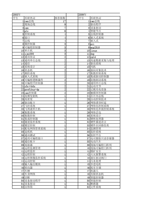
数控系统 控制器局域网总线 控制器 微处理器 开放式主机控制器接口 建模 广义预测控制 嵌入式网关 嵌入式操作系统 嵌入式linux 多机通信 多功能车辆总线 外设组件互连标准 增广状态向量 图像采集 图像传感器 双ahb总线 单片机 分布式控制 冗余控制系统 关节控制器 仿人机器人 以太网 从设备 中断 三级控制 μ clinux wdm verilog us/os-ⅱ toucan tms320vc5509 tms320lf2407 sopc sd卡 s3c2410 rs422 rs-485总线 rs-232 profibus-dp现场总线 plc pci9054 pca82c250 pc/104总线 ncs mmc卡 mcp2515 lpc2368 lpc2294 linux系统 i2c总线 hdl gprs fpga
科研热词 can总线 现场总线 can plc 控制系统 接口 总线 微控制器 可编程控制器 单片机 sja1000 通讯协议 通用串行总线 通信 系统设计 状态机 测控系统 嵌入式系统 可编程逻辑器件 可编程序控制器 s3c44b0x profibus-dp can控制器 高频发射机 高密度 驱动板卡 飞控系统 飞利浦单片机 集散系统 集散控制 集成控制器 隧道监控系统 镀层控制 配电网络管理系统 造纸机 通讯测试 通用可编程接口 通信板卡 连接器 远程监测管理 远程监控 远程控制 远程图像监控系统 运动控制 输入输出模块 转向器 车辆 车身网络 诊断 设备驱动程序 设备驱动 自络简
科研热词 can总线 驱动程序 设备驱动 智能节点 总线控制器 嵌入式系统 嵌入式 pci mcp2510 linux dsp cpld 高速数据采集与处理 驱动系统 风机 面向对象技术 集散控制系统 集成驱动控制器 防抱制动系统 通用串行总线 运动关节 记载光电设备 触摸屏控制器 芯片内总线 自动控制技术 网络诱导时延 网络化控制系统 网络化串级控制系统 网络丢包 系统设计 硬核处理器 硬件描述语言 硬件在回路仿真 监测管理 监控系统 监控平台 电可擦除只读存储器 电动汽车 现场可编程门阵列(fpga) 现场可编程门阵列 煤矿安全 火灾报警系统 液压驱动阀门 污水处理 步进电机 机车空调 机器人 有限状态机 智能控制器 智能控制 断路器111 112 113 114 115 116 117 118 119 120 121 122 123 124 125 126 127 128 129 130 131 132 133 134 135 136 137 138 139 140 141 142 143 144 145 146 147 148 149 150 151 152 153 154 155 156 157 158 159 160
钣金中英文术语
钣金工艺专业术语按基本工艺顺序:1、剪料:指材料经过剪板机得到矩形工件的工艺过程。
2、下料:指工件经过LASER切割或数控冲床冲裁的工艺过程。
3、落料:指在普通冲床或其他设备上使用模具加工得到产品形状的工艺过程。
4、冲孔:指工件由普通冲床和模具加工孔的工艺过程。
5、折弯:指工件由折弯机成型的工艺过程。
6、成形:指在普通冲床或其他设备上使用模具使工件变形的工艺过程。
7、抽孔:也叫“翻边”,指在普通冲床或其他设备上使用模具对工件形成圆孔边翻起的工艺过程。
8、攻牙:指在工件上加工出内螺纹的工艺过程。
9、扩孔:指用钻头或铣刀把工件上小孔加工为大孔的工艺过程。
10、沉孔:指为配合类似沉头螺钉一类的连接件,而在工件上加工出有锥度的孔的工艺过程。
11、压铆:指采用冲床或油压机把压铆螺母、压铆螺钉或压铆螺母柱等紧固件牢固地压接在工件上的工艺过程12、涨铆:指先将工件沉孔,再采用冲床或油压机把涨铆螺母牢固地压接在工件上的工艺过程。
13、拉母:指采用类似铆接的工艺。
用拉母枪把拉铆螺母(POP)等连接件牢固地连接在工件上的工艺过程。
14、拉铆:指以拉铆枪为工具用拉钉将两个或两个以上工件紧密地连接在一起的工艺过程。
15、铆接:用铆钉将两个或两个以上工件面对面连接在一起的工艺过程,若是沉头铆接,需将工件先进行沉孔。
16、冲凸包:指在冲床或油压机用模具使工件形成凸起形状的工艺过程。
17、冲撕裂:也叫“冲桥”,指在冲床或油压机用模具使工件形成像桥一样形状的工艺过程。
18、冲印:指使用模具在工件上冲出文字、符号或其他印迹的工艺过程。
19、切角:指在冲床或油压机上使用模具对工件角进行切除的工艺过程。
20、冲网孔:指在普通冲床或或数控冲床上用模具对工件冲出网状的孔。
21、拍平:指对有一定形状的工件过渡到平整的工艺过程。
22、钻孔:指在钻床或铣床上使用钻头对工件进行打孔的工艺过程。
23、倒角:指使用模具、锉刀、打磨机等对工件的尖角进行加工的工艺过程。
西门子凯姆尼茨工厂采用自动化小型零件拣选系统说明书

SiemensChemnitz, GermanyLarger capacities on a smaller areaDematic optimises Siemens small parts warehouse in collaboration with STILLThe company decided to switch to a goods-to-person small item picking system featuring an AutoStore ™ system. Long-time partner, Still Intralogistics Consulting, developed the new logistics concept, which included the automation of the small parts warehouse with an AutoStore system. Siemens commissioned intralogistics specialist Dematic with thecompact small parts picking system and the direct connection to the conveyor system.Around 46,000 switchgears and customised electroniccomponents for the global market are manufactured annually at Siemens WKC. Over the years, the volume and throughput in the warehouse have increased significantly. This made it necessary to reorganise the entire warehouse management: “Until then, we were still working with a manual modular rack warehouse,” reports Carsten Sambo, Head of Inbound Logistics, Siemens WKC. However, the former manual warehouse was no longer meeting current requirements.Development, engineering, production,testing, and pre-commissioning — theSiemens plant for Combination Technology in Chemnitz, Germany (Siemens WKC) is a leader in switchgear construction for machine tools and production machines in Europe. Here, the technology corporation manufactures advanced electrical equipment as well as assemblies and devices formachine and plant manufacturers worldwide. This also includes projects in the logistics and automotive industries. Its previous manual shelf storage system for small parts hadreached its capacity limits, so Siemens WKC was looking for a more efficient solution.“With the new warehouse, we are well prepared for the future ...”Carsten SamboHead of Inbound Logistics, Siemens WKCC A S E S T UD YAutomation of the Production Warehouse with AutoStoreSiemens initiated the search for a new solution: “Our goal was to make planning and production as efficient as possible. At the same time, the lead time was to be reduced and, of course, the costs were to be lowered,” explains Sambo. The new storage systems, including the conveyor technology, needed to be installed on the same floor space in the existing building and during ongoing operations.Long-time partner, Still Intralogistics Consulting, took on the initial planning of the logistics concept. This included automating the small parts warehouse with an AutoStoresystem to improve the supply of small parts to production. “We already had very good experience with an AutoStore storage system at a Siemens plant in Bad Neustadt (EWN),” explains Sambo. It accommodates up to four times more stock than the previous manual system. After only a short introductory phase, the Siemens WKC also achieved improved picking performance with 75 retrieval positions per hour (previously only 30 retrieval positions per hour). With the help of thesystem, this performance will increase by at least another 15 per cent.As a global distribution partner for AutoStore, Dematic was brought in for its extensive experience and expertise. Siemens commissioned Dematic (a sister company of STILL in the KION Group) as a system integrator to implement the AutoStore system and connect it using Dematic conveyor technology for automation that optimizes the material flow for production supply. A major advantage of this unit load picking solution is that it requires very little space. Siemens can use the space gained for storing larger material items, such as enclosures for switchgear. STILL supplied a racking system for around 12,000 storage locations and 2,100 square metres of platform space as part of the overall logistics concept. Capacities significantly increasedThe conveyor system implemented by Dematic has two levels. In the goods receiving area, incoming parcels are first scanned and transported to the upper level via a lift. There, the goods are automatically and randomly distributed to the eight transfer stations. Empty AutoStore totes from the lower level go to the workstations. The totes are loaded with inventory and conveyed to the automatic small parts store. A scale checks the weight of the totes to ensure that they do not exceed the permissible maximum weight of 30 kilograms. Transfer cells automatically deliver the totes into the AutoStore system where the mobile robots can then take the inventory and store it. The compact AutoStore system itself occupies an area of only 760 square metres. It contains a total of more than 45,000 bins, which are divided into different compartments and can thus hold several different products.With a request comes from production, the picking process starts — the provision of goods to the internal logistics, which prepares the materials according to production requirements and makes them available for production. The inventory for the orders are collected by the 34 mobile robots that travel on top of the AutoStore system. They pick the boxes from the grid and bring them to the port, where employees can carry out their picking activities without interruption. Previously, they had to travel long distances to pick the individual items. With the same number of employees, Siemens can now handle more orders in less time. “The system is highly efficient and with significantly fewer errors in the picking process,” says CarstenSambo.TECHNICAL DATA • 8 Transfer Stations• AutoStore ® foot print: 760 suqare metres • 45,000 bins • 34 robots • 5 picking ports•7.000 different picking positions dailyp o w e r t h e f u t u r e o f c o m m e r c e d e m a t i c .c o m2O r d e r -N o . C E _C S -1080-E N | 09/21 +49 69 583025-0CUSTOMER BENEFITS • Four times more stock in the same floor space• No more unproductive walking routes • Lower error rate• Decentralised organisation of robots minimises downtime• Modular design allows for easy expandability •Forecasting function and night shift reallocation allows faster access to the required goodsABOUT THE CUSTOMERThe Siemens Systems Engineering Plant (WKC) in Chemnitz has a long tradition in controlcabinet construction for machine tools as well as a wide range of industries in general mechanical and plant engineering. This also includesprojects in the logistics and automotive sectors. The range of services includes the completespectrum from application engineering, material logistics and assembly of electrical equipment to testing and pre-commissioning. Deliveries are made to customers worldwide. The specific scope of services is determined individually by the respective customer on an order-by-order basis. WKC is also a recognized competence centre for the climatization of control cabinets. It has his own test laboratory with associated possibilities for performing load test. WKC is in addition a certified UL panel shop.Equipped for the futureThe AutoStore system can store up to four times more stock in the same footprint than conventional storage systems.“The cube-storage system is a self-supporting aluminium grid whose modular structure allows containers to be stacked closely next to and on top of each other. Furthermore, it is organised in a decentralised manner — if a robot breaksdown, the system continues to run,” explains Sambo, adding, “We have daily call-offs of more than 7,000 different picking positions. To be able to access the required goods quickly in the morning, we have programmed a forecast function for stock removal or night shift transfer.” Overnight, the demand for the next day is checked. The determined materials are transferred from the lowest levels of the AutoStore system to the upper area of the grid. “This ensures that the required containers can be accessed quickly with the start of the early shift.”The small parts warehouse concept was developed with close collaboration among Siemens, Dematic, and STILL. In the end, Sambo sums it up, “We are now well prepared for the future, with scalability already taken into account during the planning stage. We’ve been able to increase the storage and picking capacities as well as make the entire warehouse management more efficient.” The fact that the production supply was maintained without interruptions during installation was a personal highlight for the Siemens project manager.。
西门子MM420变频器简明操作手册
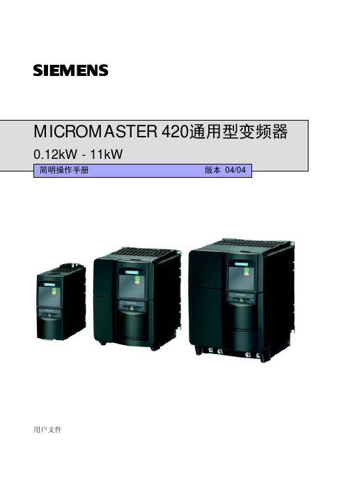
0.12kW - 11kW
简明操作手册
版本 04/04
用户文件
警告, 注意和说明
以下的“警告”,“注意”和“说明”是为了您的安全而提出的,是防止设备或与其连接的机械部 件受到损伤而采取的一项措施。在处理 MICROMASTER420 变频器的相关事项时,通常都要涉及 本节中列出的“警告”,“注意”和“说明”,它们分为以下几类:常规的,有关运输和存放,调 试,操作,维修以及拆卸和废品处理。
2
电气安装 .............................................................................................................................................2-1
6.2.1
串行接口 (USS) ..................................................................................................6-4
6.2.2 命令信号源的选择 ..............................................................................................6-4
2.1
技术规格 ..............................................................................................................................2-1
珠海莱联自动划片机教学
珠海莱联自动划片机教学珠海莱联自动划片机教学一、引言在科技不断进步的时代,自动化技术的应用已经深入到各个行业中,其中包括了制造业。
作为制造业中的关键环节,切割技术的发展对于产品质量和生产效率有着至关重要的影响。
在针对电子元件和半导体等脆性材料进行切割时,传统的手工操作往往容易引发材料损坏和不均匀的切割面质量。
为了解决这一问题,珠海莱联自动划片机应运而生。
本文将对珠海莱联自动划片机进行深入解析,并为读者提供详细的教学。
二、珠海莱联自动划片机的原理1. 切割原理珠海莱联自动划片机采用的是先进的切割技术,主要基于高速旋转的切割刀片与待切割材料的相对运动,通过刀片对材料进行切割,实现高精度、高效率的划片操作。
切割过程中,自动划片机根据预设的参数和划片路径,控制切割机械手在三维空间内精确移动,同时控制切割刀片的旋转速度和切割力度,以保证切割操作的稳定性和精准度。
2. 排列原理在自动划片机的切割过程中,我们通常需要将待切割材料按照一定规则排列,以提高生产效率并减少材料浪费。
珠海莱联自动划片机通过先进的排列算法和图像识别技术,能够自动检测和识别待切割材料的尺寸、形状和位置,进而智能地调整划片路径和顺序,以实现材料的最佳排列。
三、珠海莱联自动划片机的特点和优势1. 高精度珠海莱联自动划片机采用先进的传感器和控制系统,能够精确测量和控制切割力度、切割速度和切割角度等参数,以达到最佳的切割效果。
其精确的位置控制和图像识别功能,可以在划片过程中检测材料的位置偏差并实时调整切割路径,从而保证切割的精准度和一致性。
2. 高效率相比传统的手工划片操作,珠海莱联自动划片机具有更高的生产效率。
自动划片机可以连续、稳定地工作,大大提高了划片速度和生产能力。
自动划片机的智能排列功能,能够根据材料尺寸和形状的不同,自动调整划片路径和顺序,以实现最佳的排样效果,减少材料浪费。
3. 安全性在切割过程中,珠海莱联自动划片机注重使用者的安全。
浩宝回流焊

贰 页面介绍
系统主页面:
➢ 实时显示回流焊炉当前生产状态:等待、加热、恒温、降温、报警。 ➢ 当前工作模式 ➢ 当前炉子实际温度及设置温度 ➢ 当前炉子运输实际速度及设定速度 ➢ 当前炉子导轨实际宽度及设定宽度 ➢ 当日产品生产数量/总数量 ➢ 当前炉子风机设定频率和风机工作状态 ➢ 当前氧气分析仪工作状态和氮气浓度值 ➢ 当前控制按钮状态
肆
设备维护保养
检查各个原点信号灯是否正常工作
说明:本设备上共有 2 组,2 个原点信号开关,分别控制 X,Y 轴原点信号。正常情况下 到位信号灯会熄灭,无遮盖时信号灯亮灯。
肆
设备维护保养
丝杆、导轨部分润滑保养
说明:丝杆、导轨是设备运行的主要传动部件,保养方面最为重要,以保证设备的传动和 定位精度。进行年度大保养时要注意清除陈油及灰尘,重新涂注新油
肆
设备维护保养
丝杆、导轨部分润滑保养
说明:丝杆、导轨是设备运行的主要传动部件,保养方面最为重要,以保证设备的传动和 定位精度。进行年度大保养时要注意清除陈油及灰尘,重新涂注新油
肆
设备维护保养
过滤网保养
说明:使用链条清洗剂兑水(1:5-8)浸泡20分钟。加热水效果更佳
肆
设备维护保养
散热风扇保养
说明:使用气枪对散热风扇进行清洁
壹 设备技术参数
壹 设备技术参数
壹 设备技术参数
壹 设备技术参数
贰
页面介绍
贰 页面介绍
面板操作介绍:分为单轨与双轨两种
贰 页面介绍
面板操作介绍:
注意:导轨宽窄调节与上炉开启均设有极限保护开关, 在极限位置只有反向动作有效; 操作时需注意安全, 如有异常可及时松开或按下紧急制停止动作。
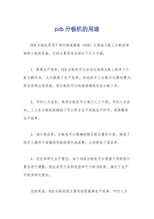
pcb分板机的用途
pcb分板机的用途
PCB分板机是用于将印刷电路板(PCB)从原始大板上分割成单
独的小板的设备。
它的主要用途包括以下几个方面:
1. 提高生产效率,PCB分板机可以自动化地将大板上的多个小
板分割开来,大大提高了生产效率。
传统的手工分板方式费时费力,而且容易出现误差,而分板机可以快速准确地完成分板工作。
2. 节约人力成本,使用分板机可以减少人工干预,节约人力成本。
工人在分板机的辅助下可以更专注于其他生产环节,提高整体
生产效率。
3. 减少废品率,分板机可以精确控制分板位置和力度,避免了
因手工操作不准确而导致的损坏或浪费,从而降低了废品率。
4. 适应多样化生产需求,由于PCB分板机可以根据不同的设计要求进行调整,因此适用于各种类型和尺寸的PCB板,满足了生产
中的多样化需求。
总的来说,PCB分板机的主要用途是提高生产效率、节约人力
成本、减少废品率,并且适应多样化的生产需求。
这些特点使得分板机在电子制造行业中起着非常重要的作用。
PCB工序设备产能估算
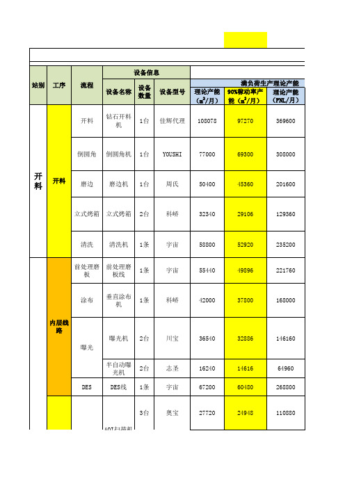
啤机
啤
4台
荣华
30643
27579
510720set
PTH前处理 磨板
去毛刺机
1条
宇宙
沉铜/
沉铜
自动沉铜 线
1条
全板电
镀
全板电镀
全板电镀 线
1条
湿
制 程
整板清洗
整板清洗 线
1条
部
分
图形电镀
图形电镀 线
1条
图形电
镀/蚀
刻
蚀刻(褪 膜/蚀刻/ SES线 1条 褪锡)
前处理磨 前处理磨
板
板线
1条
竞铭 竞铭 宇宙
308000 201600
立式烤箱 立式烤箱 2台
科峤
32340
29106
129360
清洗
清洗机 1条
宇宙
前处理磨 前处理磨
板
板线
1条
宇宙
涂布
垂直涂布 机
1条
内层线 路
曝光
曝光机 2台
半自动曝 光机
2台
DES
DES线 1条
科峤
川宝 志圣 宇宙
58800 55440 42000
36540 16240 67200
1140
11472
1485
11580
125330
4476
199584 152064
7128 5431
99792
3564
1119
1332
1782 1358
19896 8016
891
(5052)
135475set
1320
290
374976set
13392
自动化方案
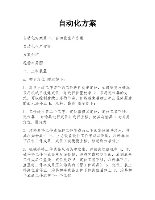
自动化方案自动化方案篇一:自动化生产方案自动化生产方案方案介绍现场布局图一. 上料装置a. 初步定位图示如下:1. 对从上道工序留下的工件进行初步定位,如遇到突发情况采用机械手视觉定位,并进行位置校准2. 采用定位器的方式,可以控制后续工序的节奏,并能避免后续工序出现问题后前面无法停止 b. 取料,翻身图示如下:1. 工件进入第二个工序,定位器将其定位,定位工装下移,定位器-1对治具进行定位并进行上移,使其与治具-1对齐并定位,固定好2. 顶料器将工件成品和工件半成品从下面定位好并顶出,使其压如治具-1中,上方吸盘吸住工件半成品正面,压料器向下压住工件成品,定位工装缓慢上移,移动到位后停止3. 机械手将工件成品从治具中取出,并放到切割机中4. 机械手将工件半成品从反面吸住,并将其翻转到正面,放到原来工件成品位置处,定位放好5. 定位工装下移,压料器下压,直至将工件半成品压入治具内(原工件成品)6. 定位工装上移到位后停止,治具和半成品工件下移到位后停止7. 治具和半成品工件流向下一个工位备注:a.本方案的工件成品指贴片机此工序成品。
b.本方案的工件半成品指贴片机只贴了一面,另外一面需要流回前工序再贴的工件。
C.如果更换产品需要更换相应工装和治具。
c. 翻身后定位图示如下:1. 定位器弹起,治具停止,调节时间2. 流向下一个工位d. 成品返回图示如下:1. 传送带-1将治具送至传送带-22. 传送带-2将治具传回前方工位二. 切割装置图示如下:自动化方案篇二:自动化方案浙江亚龙教育装备股份引领教育新理念 0 创造教育新环境目录一、二、三、四、五、六、七、八、九、十、十一、报价表.................................................... ...................................................... .......................... 1 YL-235A型光机电一体化实训考核装置 ........................................................................... 2 YL-335B型自动生产线实训考核装备 ................................................... ............................ 7 YL-381F型透明液压系统综合实训装置.................................................... ...................... 16 YL-381D型液压拆装综合实训装置 ................................................... .............................. 20 YL-380A型PLC控制的气动实训装置(单面) .................................................. ............... 22 YL-569型0i mate TD数控车床实训设备 ................................................... ..................... 25 YL-558型0i mate MD数控铣床实训设备(变频主轴) (28)YL-558型0i mate MD数控铣床实训设备(伺服主轴) (31)YL-559型802C数控四合一机床实训设备 ..................................... 错误!未定义书签。
威图电柜的选型手册

800 2000 500 699 1896 7187.746
1 7187.804 2829.200 2830.200
800 2000 600 699 1896 7187.747
1 7187.803 2833.200 2834.200
800 2000 800 699 1896 7187.748
1 7187.807 2848.200 2849.200
800 2000 500 699 1896 7187.805
1 7187.804 2829.200 2830.200
800 2000 600 699 1896 7187.806
1 7187.803 2833.200 2834.200
800 2000 800 699 1896 7187.808
1 7187.807 2848.200 2849.200
2 7187.803 2916.200 2917.200
800 2000 500
- - 7187.741 1 7187.804 2829.200 2830.200
800 2000 600
- - 7187.742 1 7187.803 2833.200 2834.200
800 2000 800
- - 7187.743 1 7187.807 2848.200 2849.200
垂直型材(顶视),这种型材 和迷宫式密封提供较高的稳 定性和保护类别。
2
进入中国市场已有十二年的德国威图公司,集几十年工业 机柜系统开发生产的经验,以追求高品质及不断创新的理 念,为进一步满足中国市场的需要,推出了针对中国市场 的基本型产品线,涵盖了机柜,机箱,机柜空调及附件等 全系列产品。该系列产品采用九折型材、纳米陶瓷涂层、 电泳底漆、发泡密封等先进工艺技术,100% 的本地化生产, 可以满足客户对机柜系统的基本需求,为同类产品制定了 新的标准,为中国用户提供了更多的选择。
常见应用广泛的PCB自动分板机的6种型号简介
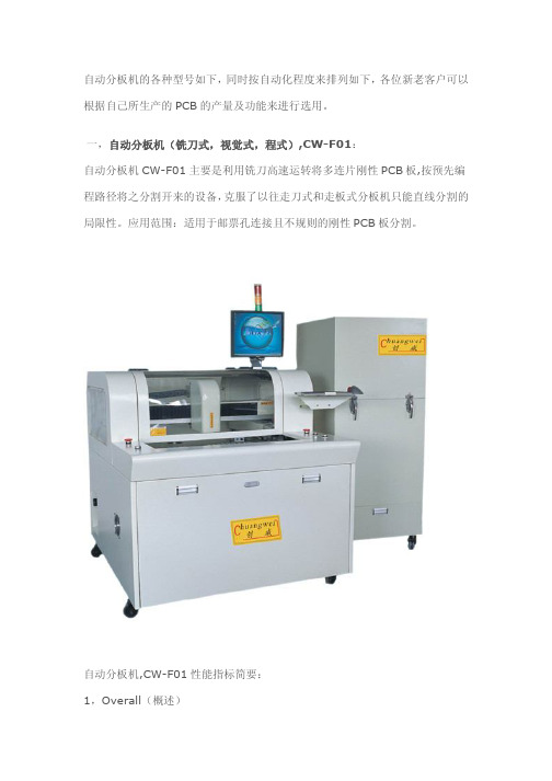
自动分板机的各种型号如下,同时按自动化程度来排列如下,各位新老客户可以根据自己所生产的PCB的产量及功能来进行选用。
一,自动分板机(铣刀式,视觉式,程式),CW-F01:自动分板机CW-F01主要是利用铣刀高速运转将多连片刚性PCB板,按预先编程路径将之分割开来的设备,克服了以往走刀式和走板式分板机只能直线分割的局限性。
应用范围:适用于邮票孔连接且不规则的刚性PCB板分割。
自动分板机,CW-F01性能指标简要:1,Overall(概述)设备尺寸:1220mm*1450mm*1420mm重量:500KG底脚可调高度: 60~110mm2,Manipulator(机械手)操纵马达类型: Panasonic MINAS A4系列操纵马达重复精度: 0.001mm各轴最大工作范围: 680mm*360mm*50mm3,Work station(工作台)板的定位方式:治具定位、万能顶针定位、视觉校正上下板方式:人工放置分板最大尺寸:320mm*320mm板最大厚度:5mm二,气动式模具冲床自动分板机,CWPE(使用气动驱动模具冲切分板的方式,让一整块FPC拼板在330*220(MM)的范围的可进行一次性分切。
)1、分板机型号:CWPE2、输入电压:110/220VAC3、工作气压:0.50-0.70干燥气源4、冲切出力(吨数):3(可定制做到30吨)5、放板工作面积:330*220(MM)6、重量:530 (KG)7、机器尺寸:730*810*1700(MM)三,机构式模具冲床自动分板机,CWPL(使用机构运动方式驱动模具冲切分板,让一整块FPC拼板在460*320(MM)的范围的可进行一次性分切。
)1、分板机型号:CWPL2、输入电压:110/220VAC3、冲切出力(吨数):8T4、放板工作面积:460*320 (MM)5、机器重量:680 (KG)6、机器尺寸:930*880*1230(MM)四,走刀式自动分板机,CWV-1A分板机型号:CWV-1A最大分板长度:460mm(可订制不同长度)分板速度:可调节分四档100,200,300,500mm/sec分板厚度:0.6-3.5mm使用电压和功率:220VAC -- 90W机器重量:55kg机器尺寸:770*510*450mm五,加装输送带的走刀式自动分板机,CWV-2A1、分板机型号:CWV-2A2、最大分板长度:460mm(可订制不同长度)3、分板速度:可调节分四档100,200,300,500mm/sec4、分板厚度:0.6-3.5mm5、输送带长度:1350mm(可订制不同长度)6、使用电压和功率:220VAC -- 150W7、机器重量:75kg8、机器尺寸:770*460*570mm六,走板式LED自动分板机,三刀式LED铝基板自动分板机,CWVC-3S(特别擅长于分切各种长的LED铝基板,如0.8m,1.2m,2m,4m等LED铝基板,至今为至此型号已成功用于中山,天津,江苏等地的多家LED行业客户。
271-140342 使用手册 操作 安装 维修说明书
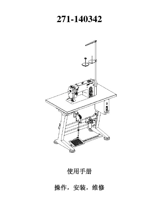
271-140342使用手册操作安装维修前言本手册目的是帮助用户熟悉本机并且根据介绍充分合理发挥各种功能应用本手册包含如何安全正确和经济使用本机的重要信息遵守本手册可避免危险发生减少维修成本和停工增加机器的可靠性和寿命本手册可补充现存的国家事故预防和环境保护规定本手册必须每台机器一册任何使用本机的人员必须阅读和使用本手册这表示-- 操作包括准备在缝纫过程中的故障排除清洁润滑-- 维修保养检查修理等-- 运输用户还必须保证只能由授权的人员使用本机用户必须每班至少检查机器一次看看是否有明显的损坏并且及时报告可能危及安全的任何变化包括工作性能用户必须确保只在理想的工作状况下使用本机器切勿拆卸任何安全装置或使之失去功能为了安装其它装置维修或保养如需要拆下安全装置一旦完成保养和维修工作后必须重新再装上未经同意修改本机器生产商对由此造成的损坏不负责任请遵守机器上的所有安全和危险劝告机器上所有黄底黑字的标示标出了十分危险的部位例如被压扁割伤针刺或撞坏的危险除了遵守本使用手册的规章外也请遵守一般安全和事故预防规定一般安全措施不遵守下列安全措施会引起人身伤害或损坏机器1本机使用前应充分了解本使用手册并由受过相应培训的人员操作2使用本机前同时请阅读电机安全规定和说明书3本机只可用作规定用途不允许在没有安全装置情况下使用本机请遵守所有的有关安全规定4在更换定规零部件例如机针压脚针板送料牙和梭芯在穿线离开工位维修过程中必须断开本机的主电源开关5每日的维护工作必须由受过相应培训的人员完成6维修转换和特别保养工作必须由技术人员或受过相应培训的人员完成7对于气动装置上的保养或维修工作断开机器和空压机的连接最大本7-10帕在断开前减少油水分离器的压力除此以外只可由受过相应培训的技术人员进行调整和检查功能8电器部分的工作必须由技术人员或受过相应培训的人员完成9不允许对带电的零部件和机构进行操作除非按DIN VDE 0105规范的规定10机器的转换或改动必须得到我们的同意并且遵守所有的安全措施11维修时只可使用得到我们批准的替换件12整套机器必须符合EC条例禁止只使用机头非标准配套必须绝对遵照这些标志标出的安全说明小心人身伤害同时也请注意一般安全说明目录页码前言和一般安全信息第1部分271-140342型直流驱动平缝机的操作说明1产品介绍 (7)2正确使用 (7)3具体机种 (7)4选购装置 (8)5技术规格 (8)6操作 (10)6.1 穿面线 (10)6.2 调节面线张力 (10)6.3 放松面线张力 (10)6.4 绕底线 (11)6.5 装梭芯 (12)6.6 调节底线张力 (13)6.7 更换机针 (14)6.8 调节夹线器 (15)6.9 调节压脚压力 (16)6.10 调节针距 (16)6.11 压脚提升 (17)6.12 使压脚停于高位 (17)6.13 机头上的键盘 (18)7缝纫 (18)8保养 (21)8.1 清洁和检查 (21)8.2 润滑 (22)1产品介绍杜克普爱华271-274平缝机为用途较广泛的特殊缝纫机2正确使用271-274为可用于缝纫薄料的特殊缝纫机这类缝料通常为织物或皮革通常用与服装和室内装饰业另外也可用本机进行技术缝然而操作人员必须了解可能产生的困难因为一方面这类应用相当少另一方面又是多种多样的根据了解的结果采取相应的预防措施线缝通常用规格达到30/2NM化纤线或30/3NM包芯线的缝纫线要使用其它缝线必须首先估计由此造成的故障如有必要采取相应的措施缝纫机只可在干燥和干净的环境内安装和使用如果在其它没有达到上述要求的环境中使用本机可能有必要采取进一步的得到认可的措施见EN60204-311999作为工业机生产商我们认为至少是半熟练的操作人员使用本产品所以认定他们知道所有通常的操作适用范围安全情况3具体机型基本型单针双锁式线迹缝纫机配备下送料和剪线器用于薄到中厚料针迹长度4mm内藏式驱动直流驱动电机271-140342型作为基本型号具有自动电磁加固和电磁压脚提升标准配备线缝过程中加固和高低针位功能单行线迹并且开始或取消加固配备Efka DC1500 缝纫电机E27用于薄料到中厚料活压脚4选购装置机器上不提供选购装置然而通过备品备件订购在价格表中提到的271-140342的所有选购装置都可装到机器上5技术规格271系列271-140342线迹类型 301旋梭类型小针数 1 机针型号 134797 或Sy 195 501机针规格最大取决于E no. [Nm] 70-120最大的面线规格 30/3最大针距--向前[mm ] --向后[ mm ] 4 4最大缝速 [min-1] 5500出厂标准缝速 [min-1] 4800压脚行程--抬起时[mm] 8工作压力[ bar] --空气消耗[NL] --长度宽度高度[mm] 500╳175╳380重量[kg ] 35设计的电压范围[V/Hz] 1╳190-240V50/60出厂时设计的电压[V/Hz] 1╳230V50/60Hz设计功率 [KV A] 0,5噪音根据DIN45635-48-A-1-KL2车间相应的释放值Lc [dB(A)] 82针距[Mm] 3 2 缝速 [Min-1] 4800缝料G1 DIN 23328 2层图a. 正确的线迹交织点处在缝料的中央图b. 面线张力不足或底线张力太强图c. 面线张力太强或底线张力不足6.1穿面线小心受伤 断开电源开关只有缝纫机关闭时才可穿面线-- 如图所示把线团放到线架上第14页 -- 按前一页上的图穿面线6.2面线张力调节调节面线预张力在剪线时面线的主夹线板4是分开的为了安全剪线有必要在剪线过程中使面线保持微弱的张力这就要通过面线预夹线板1同时面线预夹线板1影响面线线头的剪线长度从而影响到下一可靠始缝要求的缝线长度基本位置 转动调节螺母2直至其前面碰到螺栓3 开始缝线太短 顺时针转动调节螺母2 开始缝线太长逆时针转动调节螺母2调节主夹线板面线预夹线板1和主夹线板4一起决定线缝要求的缝线张力见图a. 调节 相应转动调节螺母4 增加张力 顺时针转动调节螺母4 减小张力逆时针转动调节螺母463放松面线张力自动在剪线时主夹线板4自动打开-- 把梭芯放到绕线器轴1上-- 如图所示穿线-- 顺时针在梭芯上绕线-- 拉线头通过剪线夹并割断-- 逆梭芯摆动绕线器盖3-- 合上主开关-- 开始缝纫过程-- 当到达设定的梭芯满线量见维修说明绕线器自动断开小心受伤断开电源开关只有缝纫机关闭时才可装梭芯拆下梭芯-- 抬起梭芯套定位器1-- 同时取下梭芯套2和梭芯-- 从梭芯套2上取下空梭芯安装绕满线的梭芯-- 把绕满线的梭芯3放入梭芯套2中-- 拉底线穿过夹线簧6下的开槽4下面并穿过孔5 -- 从梭芯套2中拉出底线约5厘米拉线时梭芯必须按箭头所示方向转动-- 再把梭芯套2装入旋梭中-- 关上梭芯套定位器16.6调节底线张力小心受伤断开电源开关只有缝纫机关闭时才可调节底线张力调节底线张力底线张力必须调节到使线缝象第六节的图a.所示-- 如果建议底线张力例如为30克则15克应通过制动簧1获得另15克通过夹线簧4获得-- 下面为夹线簧4的基本调节梭芯套必须以自重缓慢落下见章节6.5的图制动簧1在剪线过程中阻止梭芯继续出线一个程序中调节二夹线值的方法如下-- 向后转动调节螺钉3直至夹线簧4的张力完全放松-- 通过转动螺钉2调节制动簧1使建议的底线张力值的一半通过制动簧获得-- 把梭芯装入梭芯套中并穿底线见章节6.5-- 把梭芯套和梭芯放入旋梭中-- 转动手轮直至缝纫机缝出一线迹-- 借助面线拉底线到针孔的上部-- 以45°的角度按缝纫方向引底线力量应感觉到约为张力值的一半然后拧紧螺钉3到建议的张力值6.7更换机针小心受伤断开电源开关只有缝纫机关闭时才可更换机针-- 松开螺钉1卸下机针-- 在针杆4的孔中向上推新机针直至不动注意槽2必须面向梭尖3见草图-- 拧紧螺钉1注意换成不同规格的机针后必须校正旋梭到机针的间隙见维修手册不遵照上面的校正会引起下列问题-- 换成了较细的机针-- 换成了较粗的机针-- 跳针-- 断线-- 损坏梭尖-- 损坏机针形成线迹要求的面线数量由调线器2调节只有调节精确的调线器才能确保理想的缝纫效果调线器的调节取决于下列因素 -- 针迹长度 -- 缝料厚度-- 所用缝线的特性调节正确时面线环6必须滑过旋梭不过分略微有一点张力小心受伤 断开电源开关只有缝纫机关闭时才可调节夹线器-- 松开螺钉5 --调节调线器2垂直线3和刻度尺4作为调节的辅助指导值 2.5-- 拧紧螺钉5需要的压脚压力由调节螺钉1调节-- 松开锁紧螺母2-- 增加压脚压力=顺时针转动调节螺钉1减小压脚压力=逆时针转动调节螺钉1-- 再拧紧锁紧螺母26.10调节针距调节盘向前缝纫的针距由调节盘3设定倒缝的针距由调节盘4设定6.11压脚提升电磁压脚提升-- 踩踏板后半部踏板保持在这个位置压脚保持抬起-- 终缝处完全踩住压脚后部以启动剪线器并抬起压脚6.12使压脚处在提升状态机械或电磁抬起的压脚可通过按钮1使压脚保持在提升状态例如绕底线-- 机器空转时踩压脚后半部压脚抬起-- 按下按钮1并松开踏板抬起的压脚保持提升状态-- 再踩压脚后半部压脚被松开6.13机壳上的键盘没有功能设定或取消始缝或终缝加固 如果起始或结束加固一般是开着的则操作该键关闭下一次加固 如果起始或结束加固一般是关着的则操作该键下一次将加固把机针定在高位或低位该键的功能可通过参数F-140DA 220C 建立 1=机针高位2=机针高位/低位3=单线迹4=单线迹针距较短如果线迹改变正在处理中 工厂设定1=机针高位手工倒缝 只要键被按着机器一直倒缝黄灯LED 显示器: 当 LED 亮着选中的功能发生作用绿灯显示直流驱动电机开启 小心受伤直流驱动电机合上时绿色LED 亮不应进行下列工作--穿面线后底线--更换梭芯更换机针 --调节夹线器--运动部位的所有工作7缝纫缝纫时必须先具备下列条件-- 下列功能在控制面板上设定 开始和结尾加固开剪线前后缝纫压脚位置低 剪线前机针位置低位置1 -- 主开关合上-- 上一次缝纫过程为终缝加固和剪线缝纫过程中操作和功能顺序缝纫程序操作 / 解释缝纫开始前初始位置- 踏板在自然位置缝纫机空载机针上压脚下.踩踏板后部压脚抬起在始缝时缝料定位 -- 缝料定位- 松开踏板压脚下落到缝料上始缝时向前踩踏板并且不放开始线缝 -起始加固然后机器继续缝纫速度由踏板决定按键1取消加固线缝开始时没有加固 -- 向前踩踏板- 机器缝纫速度由踏板决定在线缝中间中断缝纫程序- 松开踏板自然状态位置机器停在第1位置机针下位- 压脚在下面踩踏板后半部缝纫角度 -机器停在第1位置机针下位压脚抬起- 围绕机针转缝料缝纫程序操作 / 解释终缝时结束线缝- 完全踩住踏板后部并踩住不放终缝加固剪线机器停在第2位压脚抬起卸下缝料按键1取消加固终缝不加固结束线缝 -完全踩住踏板后部终缝不加固剪线机器停在第2位压脚位置由踏板位置决定a)踩住踏板后部并踩住不放- 压脚抬起b) 放松踏板自然状态位置- 压脚落下-小心受伤断开电源开关只有缝纫机关闭时才可保养机器保养工作必须至少按表格中列出的保养间隔进行参见栏目中的工作时间当加工棉绒成分较多的面料保养间隔应缩短8.1清洁和检查保持机器清洁可防止故障发生保养工作措施工作时间机头- 清除灰尘线头和切屑需特别清洁的地方- 针板下- 送布牙连杆- 旋梭周围- 梭芯套- 剪线器- 机针部分8- 清洁挡油板机头下-清除垃圾和切屑40小心受伤润滑油会引起皮肤发炎避免与皮肤长时间接触如果皮肤碰到了润滑油请彻底洗干净注意润滑油的处理和排放有专门的规定把用过的润滑油送到指定的接收点请保护环境切勿泄漏本机器加油只可使用埃索SP-NK10润滑油或符合下列规格的相当产品-- 40° C 时粘度10 mm 2 /s-- 燃点 150 °C所有杜克普爱华代理商都供应ESSO SP-NK 10零件号为2升装 9047 0000135升装 9047 000014机头加油-- 每星期检查储油器1油位不能低于MIN 标记如有必要通过油窗的加油孔加油到MAX标记旋梭加油-- 每星期检查储油器2油位不能低于MIN标记如有必要加油到MAX标记。
AT4202 04 08多路温度测试仪用户手册说明书

用户手册User’s GuideAT4202/04/08多路温度测试仪Rev.B4固件说明:适用于主程序RevA2.0及以上的版本@Instruments常州安柏精密仪器有限公司.江苏省常州市钟楼区宝龙61-3层销售服务电子邮件: *****************技术支持电子邮件: ****************©2005-2015 Applent Instruments Ltd.AT4202/4204/4208 用户手册2声明根据国际版权法,未经常州安柏精密仪器有限公司(Applent Instruments Inc.)事先允许和书面同意,不得以任何形式复制本文内容。
安全信息为避免可能的电击和人身安全,请遵循以下指南进行操作。
免责声明用户在开始使用仪器前请仔细阅读以下安全信息,对于用户由于未遵守下列条款而造成的人身安全和财产损失,安柏仪器将不承担任何责任。
仪器接地 为防止电击危险,请连接好电源地线。
不可在爆炸性气体环境使用仪器不可在易燃易爆气体、蒸汽或多灰尘的环境下使用仪器。
在此类环境使用任何电子设备,都是对人身安全的冒险。
不可打开仪器外壳非专业维护人员不可打开仪器外壳,以试图维修仪器。
仪器在关机后一段时间内仍存在未释放干净的电荷,这可能对人身造成电击危险。
不要超出本说明书指定的方式使用仪器超出范围,仪器所提供的保护措施将失效。
警告:不要加直流电压或电流到测试端,否则会损坏仪器。
安全标志:设备由双重绝缘或加强绝缘保护废弃电气和电子设备 (WEEE) 指令 2002/96/EC切勿丢弃在垃圾桶内有限担保和责任范围 3有限担保和责任范围常州安柏精密仪器有限公司(以下简称Applent)保证您购买的每一台AT4202/4204/4208在质量和计量上都是完全合格的。
此项保证不包括保险丝以及因疏忽、误用、污染、意外或非正常状况使用造成的损坏。
本项保证仅适用于原购买者,并且不可转让。
自发货之日起,Applent提供玖拾(90)天保换和贰年免费保修,此保证也包括VFD或LCD。
QBL4208-x-1k NEMA17(42mm)3相BLDC电机加小型光增量编码器套件说明书
QBL4208-100-04-025-1K QBL4208-61-04-013-1KEncoder +Motor Kits for BLDCQBL4208-x-1k Hardware ManualHardware Version V1.00|Document Revision V1.40•16.04.2021QBL4208-x-1k is a NEMA17(42mm)3-phase BLDC motor including a small size optical incremental encoder kit.Besides the standard HALL sensor signals,it comes with an encoder resolution of 64lines (4096counts).Trinamic’s BLDC motors are quality motors for universal use.They feature a long life due to ball bearings and no wearing out parts.Features •Low Cost•High Resolution •Small Dimension•Standard Incremental Encoder Inter-face•Including optional HALL SensorsApplications•Closed Loop Servo Motors •Industrial Automation•Automated Equipment •RoboticsSimplified Block Diagram©2021TRINAMIC Motion Control GmbH &Co.KG,Hamburg,Germany Terms of delivery and rights to technical change reserved.QBL4208-x-1k Hardware Manual•Hardware Version V1.00|Document Revision V1.40•16.04.20212/17 Contents1Order Codes3 2Motor Specifications and Characteristics42.1Technical and Mechanical Parameters (4)2.2Torque-Speed Diagrams (5)2.2.1QBL4208-61-04-013-1k (5)2.2.2QBL4208-100-04-025-1k (6)3Technical Specifications of the Encoders63.1Electrical Encoder Parameters (6)3.2Mechanical Encoder Parameters (7)3.3Environmental Encoder Parameters (7)4Connectors and Signals74.1Motor Connector (7)4.2Hall Signal Connector (8)4.3Encoder Connector (8)4.4Encoder Wave Form (9)5Mechanical Drawings9 6Motor Sizing116.1Peak Torque Requirement (11)6.2RMS Torque Requirement (11)6.3Motor Velocity (11)7Figures Index13 8Tables Index14 9Supplemental Directives159.1Producer Information (15)9.2Copyright (15)9.3Trademark Designations and Symbols (15)9.4Target User (15)9.5Disclaimer:Life Support Systems (15)9.6Disclaimer:Intended Use (15)9.7Collateral Documents&Tools (16)10Revision History1710.1Hardware Revision (17)10.2Document Revision (17)QBL4208-x-1k Hardware Manual•Hardware Version V1.00|Document Revision V1.40•16.04.20213/17 1Order CodesOrder Code Old Order Code Description Size mm(LxWxH)42x42x79QBL4208-61-04-013-1k QBL4208-61-04-013-1024-AT Motor+Encoder Mod-ule,NEMA173-phaseBLDC motor(3.5A/0.13Nm,4000rpm,round shaft)with inte-grated HALL sensorsand incremental en-coder kit,resolutionof64lpr(4.096cpr),ABN,TTL42x42x118 QBL4208-100-04-025-1k QBL4208-100-04-025-1024-AT Motor+Encoder Mod-ule,NEMA173-phaseBLDC motor(7.0A/0.25Nm,4000rpm,round shaft)with inte-grated HALL sensorsand incremental en-coder kit,resolutionof64lpr(4.096cpr),ABN,TTLTable1:Order codesOther encoder resolutions,signal output types,and customized motor options(without HALL signals for example)on request.QBL4208-x-1k Hardware Manual•Hardware Version V1.00|Document Revision V1.40•16.04.20214/172Motor Specifications and CharacteristicsTRINAMIC’s BLDC motors are quality motors for universal use.They feature a long life due to ball bearings and no wearing out parts.These BLDC motors give a goodfit to the TRINAMIC family of medium and high current BLDC motor modules and custom/customized solutions.2.1Technical and Mechanical ParametersThe main characteristics are:•Hall Effect Angle:120°electric angle•Shaft run out:0.025mm•Insulation Class:B•Radial Play:0.02mm450G load•Max Radial Force:28N(10mm fromflange)•Max Axial Force:10N•Dielectric Strength:500VDC For One Minute•Insulation Resistance:100M Ohm min.500VDC•Recommended Ambient Temp.:-20to+40°C•Bearing:Brushless motorsfitted with ball bearings•Coil windings in delta topologySpecifications Unit QBL4208-61-04-013-1k QBL4208-100-04-025-1k No.of Poles88No.of Phases33Rated Voltage V2424Rated Phase Current A 3.47 6.95Rated Speed RPM40004000Rated Torque Nm0.1250.25Max Peak Torque Nm0.380.75Torque Constant Nm/A0.0360.036Line to Line ResistanceΩ0.720.28Line to Line Inductance mH 1.20.54Max Peak Current A10.620Length(LMAX)mm61100Rotor Inertia kgm2x10−64896Mass kg0.450.8Table2:Electrical and Mechanical Characteristics MotorQBL4208-x-1k Hardware Manual•Hardware Version V1.00|Document Revision V1.40•16.04.20215/172.2Torque-Speed DiagramsThe torque-speedfigures detail motor torque characteristics measured in block commutation.Please be careful not to operate the motors outside the bluefield.This is possible for short times only because of a resulting high coil temperature.The motors have insulation class B.The bluefield is described by rated speed and rated torque.2.2.1QBL4208-61-04-013-1kVelocity vs.torque measured with24V supply voltage.Figure1:QBL4208-61-04-013-1k velocity vs.torque characteristicQBL4208-x-1k Hardware Manual•Hardware Version V1.00|Document Revision V1.40•16.04.20216/172.2.2QBL4208-100-04-025-1kVelocity vs.torque measured with24V supply voltage.Figure2:QBL4208-100-04-025-1k velocity vs.torque characteristics3Technical Specifications of the Encoders3.1Electrical Encoder ParametersParameter Min Typ Max Unit Supply voltage 4.55 5.5VSupply current110mARise/fall time10ns Frequency1500kHz Output Voltage"‘H"’ 2.4VInput Voltage"‘L"’0.4VMax.output current20mADisc lines64lines Resolution4096incrementsTable3:Electrical Characteristics EncoderQBL4208-x-1k Hardware Manual•Hardware Version V1.00|Document Revision V1.40•16.04.20217/17 3.2Mechanical Encoder ParametersParameter Min Typ Max Unit Hollow Diameter(symbol D in drawings)5/6.35mm Starting Torque0.8Ncm Shaft Loading Axial50N Shaft Loading Radial80N Max.RPM6000rpm Net weight30gTable4:Mechanical Specifications3.3Environmental Encoder ParametersParameter DescriptionOperating Temperature-20–+85°CStorage Temperature-20–+85°COperating Humidity RH85%max,non collecting Shock490m/s2,3Dx2times Vibration 1.2mm,10-55kHz,3Dx30min Protection IP40Table5:Environmental Specifications4Connectors and Signals4.1Motor Connector#Color Wire Type Signal Name1Yellow UL1430AWG20Phase U2Red UL1430AWG20Phase V3Black UL1430AWG20Phase WTable7:Connector and signals of motorQBL4208-x-1k Hardware Manual•Hardware Version V1.00|Document Revision V1.40•16.04.20218/17 4.2Hall Signal Connector#Color Wire Type Signal Name1Red UL1430AWG26VCC Hall Sensor+5VDC to+24VDC2Blue UL1430AWG26HALL A3Green UL1430AWG26HALL B4White UL1430AWG26HALL C5Black UL1430AWG26GND,Sensor GroundTable9:HALL sensor connector and signals4.3Encoder Connector#Color Wire Type Signal Name1Red UL2517AWG28VCC2Black UL2517AWG28GND3White UL2517AWG28A+4White/Black UL2517AWG28Black A-5Green UL2517AWG28B+6Green/Black UL2517AWG28B-7Yellow UL2517AWG28Z+8Yellow/Black UL2517AWG28Z-9Blue UL2517AWG28ShieldTable11:Connector and signals of the encoderThe required encoder cable connector is a Molex type5023800900CLIK-MATE™crimp housing using Molex type5023810000CLIK-MATE™crimp terminals.Figure3:Connection and circuit diagram for the line driver outputsQBL4208-x-1k Hardware Manual•Hardware Version V1.00|Document Revision V1.40•16.04.20219/17 4.4Encoder Wave FormFigure4:Example wave form for CCW rotation5Mechanical DrawingsFigure5:Dimensions of motor&encoder kit(all units=mm)Motor Type Body LengthQBL4208-61-04-013-1k61mmQBL4208-100-04-013-1k100mmTable13:Motor lengthFigure6:Length of motor wires/cables(all units=mm)6Motor SizingFor the optimum solution it is important tofit the motor to the application.The three key parameters are peak torque requirement,RMS torque requirement and motor velocity.6.1Peak Torque RequirementPeak torque TP is the sum of the torque due to acceleration of inertia(T I),load(T L)and friction(T F):T P=T J+T L+T FThe torque due to inertia is the product of the load(including motor rotor)inertia and the load accelera-tion:T J=T+aThe torque due to the load is defined by the configuration of the mechanical system coupled to the motor. The system also determines the amount of torque required to overcome the friction.6.2RMS Torque RequirementRoot-Mean-Square or RMS torque is a value used to approximate the average continuous torque require-ment.Its statistical approximation is with•t1:acceleration time•t2:run time•t3:deceleration time•t4:time in a moveT RMS=T2P+(T L+T F)2∗t2+(T J−T L−T F)2∗t3t1+t2+t3+t46.3Motor VelocityThe motor velocity is also dictated by the configuration of the mechanical system that is coupled to the motor shaft,and by the type of move that is to be affected.For example,a single velocity application would require a motor with rated velocity equal to the average move velocity.A point to point positioning would require a motor with a rated velocity higher than the average move velocity.(The higher velocity would account for acceleration,deceleration and run times of the motion profile).Figure6.1:Trapezoidal move and triangular move relates rated motor velocity to average move velocity for two point to point positioning move profiles.Table14:Trapezoidal and triangular move symbols7Figures Index1QBL4208-61-04-013-1k velocity vs.torque characteristic (5)2QBL4208-100-04-025-1k velocity vs.torque characteristics (6)3Connection and circuit diagram for the line driver outputs.........84Example wave form for CCW rotation9 5Dimensions of motor&encoder kit (all units=mm). (9)6Length of motor wires/cables(all units=mm) (10)8Tables Index1Order codes (3)2Electrical and Mechanical Characteris-tics Motor (4)3Electrical Characteristics Encoder (6)4Mechanical Specifications (7)5Environmental Specifications (7)7Connector and signals of motor...79HALL sensor connector and signals.8 11Connector and signals of the encoder8 13Motor length (9)14Trapezoidal and triangular move sym-bols (12)15Hardware Revision (17)16Document Revision (17)9Supplemental Directives9.1Producer Information9.2CopyrightTRINAMIC owns the content of this user manual in its entirety,including but not limited to pictures,logos, trademarks,and resources.©Copyright2021TRINAMIC.All rights reserved.Electronically published by TRINAMIC,Germany.Redistribution of sources or derived formats(for example,Portable Document Format or Hypertext Markup Language)must retain the above copyright notice,and the complete data sheet,user manual,and doc-umentation of this product including associated application notes;and a reference to other available product-related documentation.9.3Trademark Designations and SymbolsTrademark designations and symbols used in this documentation indicate that a product or feature is owned and registered as trademark and/or patent either by TRINAMIC or by other manufacturers,whose products are used or referred to in combination with TRINAMIC’s products and TRINAMIC’s product doc-umentation.This Hardware Manual is a non-commercial publication that seeks to provide concise scientific and tech-nical user information to the target user.Thus,trademark designations and symbols are only entered in the Short Spec of this document that introduces the product at a quick glance.The trademark designation /symbol is also entered when the product or feature name occurs for thefirst time in the document.All trademarks and brand names used are property of their respective owners.9.4Target UserThe documentation provided here,is for programmers and engineers only,who are equipped with the necessary skills and have been trained to work with this type of product.The Target User knows how to responsibly make use of this product without causing harm to himself or others,and without causing damage to systems or devices,in which the user incorporates the product.9.5Disclaimer:Life Support SystemsTRINAMIC Motion Control GmbH&Co.KG does not authorize or warrant any of its products for use in life support systems,without the specific written consent of TRINAMIC Motion Control GmbH&Co.KG. Life support systems are equipment intended to support or sustain life,and whose failure to perform, when properly used in accordance with instructions provided,can be reasonably expected to result in personal injury or death.Information given in this document is believed to be accurate and reliable.However,no responsibility is assumed for the consequences of its use nor for any infringement of patents or other rights of third parties which may result from its use.Specifications are subject to change without notice.9.6Disclaimer:Intended UseThe data specified in this user manual is intended solely for the purpose of product description.No rep-resentations or warranties,either express or implied,of merchantability,fitness for a particular purposeor of any other nature are made hereunder with respect to information/specification or the products to which information refers and no guarantee with respect to compliance to the intended use is given.In particular,this also applies to the stated possible applications or areas of applications of the product. TRINAMIC products are not designed for and must not be used in connection with any applications where the failure of such products would reasonably be expected to result in significant personal injury or death (safety-Critical Applications)without TRINAMIC’s specific written consent.TRINAMIC products are not designed nor intended for use in military or aerospace applications or environ-ments or in automotive applications unless specifically designated for such use by TRINAMIC.TRINAMIC conveys no patent,copyright,mask work right or other trade mark right to this product.TRINAMIC as-sumes no liability for any patent and/or other trade mark rights of a third party resulting from processing or handling of the product and/or any other use of the product.9.7Collateral Documents&ToolsThis product documentation is related and/or associated with additional tool kits,firmware and other items,as provided on the product page at:.10Revision History10.1Hardware RevisionTable15:Hardware Revision 10.2Document RevisionTable16:Document RevisionQBL4208-100-04-025-1K QBL4208-61-04-013-1K。
工业机器人设备清单

空气动力机械智能制造公共实训基地设备预算清单模块一工业机器人基础工作室一、工业机器人基本技能工作室总体概述工业机器人基本技能实训方案以6轴机器人工作站为核心,配套装配了操作对象承载平台、工具墙、零件箱、学习讨论区、资讯区、机器人安全工作围栏等设施设备及基础教材、仿真软件、工学结合工作页等教学配套。
为工业机器人基本技能实训提供了综合的、完整的、工学结合的解决方案。
针对工业机器人应用维护专业基础技能训练与实习,该阶属于机电工学结合类技能向工业机器人过渡的关键环节,通过简单易操作的机器人本体操作的学习,加强安全意识与规范意识的培养,让学生掌握如何与工业机器人“打交道”。
工业机器人基本技能工作室案例照片(仅供参考)(图片仅供参考、以实际二、工业机器人基本技能工作室配置清单个;高强度铝合金手电筒(3节7号电池)6LED 1个;专业级手动黄油枪400cc 1个;手用黄油枪尖嘴头 1个;手用黄油枪软管12" 1个;德式轴用直口卡簧钳7" 1把;活动扳手10" 1把;木柄安装锤45MM 1把;T 系列双头螺丝批#1&5MM×150MM 1个;2.5MM系列钢柄快脱棘轮扳手 1把;预置式扭力扳手3件套;9件套公制长球头内六角扳手 1套;塑料工具箱19" 1把;吊带1条;卸扣 2个;工业听诊器 1把10、护栏①范围:2980mm×2980mm×920mm②材质:铝型材★含工业机器人拆装与调试课程资源包1、《工业机器人拆装与调试》教材配套教学ppt一套,试题3套、课程标准1套(现场演示)2、★《工业机器人拆装与调试》跨终端网络课程1门:★基于html5开发,课程栏目满足自适应,功能栏目为首页、课程简介、课程学习、★模拟考试(可进行在线考试)、拓展资源;(现场演示)3、《工业机器人拆装与调试》网络课程符合scorm封装标准4、★7个机器人拆装重难点微课;(现场演示)5、批量六关节机器人拆装素材库、视频素材库、教材配套素材库6、提供资源能学辅教,设备与网络课程及资源库能够完整对应。
pcb分板机基本操作流程

pcb分板机基本操作流程PCB分板机(也称为分板设备)是一种用于将PCB(Printed Circuit Board,印刷电路板)从一个大面积板材中分割成多个独立电路板的设备。
以下是一个基本的PCB分板机操作流程。
1.准备工作a.检查分板机的所有部件和工具是否完好无损。
b.确保分板机的电源已连接并处于正常工作状态。
c.准备好需要分割的PCB板材和所需的分板方案。
2.设置分板参数a.打开分板机的控制界面。
b.输入所需的分板参数,如分割方式、分割路径、分割速度等。
c.检查参数设置是否正确,并进行必要的调整。
3.安装PCB板材a.将需要分割的PCB板材安装到分板机的工作台上。
b.调整PCB板材的位置和方向,确保其与切割路径对齐。
4.确定起始点a.使用分板机的光电感应系统,确定PCB板材的起始点。
b.将感应系统对准PCB板材的起始位置,并进行校准。
5.进行分板a.启动分板机,使刀具开始切割PCB板材。
b.根据设定的分割路径,精确地分割出独立的电路板。
c.根据分板机的工作原理,可能需要进行多次切割操作。
6.确认分板结果a.检查分板后的各个电路板是否完整且正常。
b.检查是否出现任何不良分割,如断裂、割伤、划痕等。
7.将分板后的电路板取出a.将分板后的电路板从分板机的工作台上取出。
b.将电路板放置在合适的位置,以便进行后续的组装、焊接等工艺。
8.清理和维护a.清理分板机的工作台和刀具,以保持其正常工作状态。
b.定期进行维护和保养,包括清洁、润滑和更换磨损的部件。
以上是一个基本的PCB分板机操作流程。
在实际操作中,根据不同的分板机型号和不同工艺的要求,可能还需要进行一些特殊的操作步骤和参数设置。
因此,在操作前,最好仔细研究和理解所使用分板机的用户手册,并遵循其操作指导。
强力电动木柴裂解机-用户手册说明书

INSTRUCTION MANUAL 1500W ELECTRIC 4 TON LOG SPLITTERModel No: THLS-4 -- Product No: 193892002ASSEMBLY REQUIREDSAVE THESE INSTRUCTIONSSPARES & SUPPORT: 01793 333212Please read & understand this manual, paying attention to the safety instructions,before use.The manufacturer reserves the right to change the product specification and liveryaccording to continued product improvements.All images used are for illustration purposes only.CONTENTSSPECIFICATIONSIMPORTANT INFORMATIONGENERAL SAFETY INSTRUCTIONSSET UP & PREPARATION FOR OPERATIONWIRING & HYDRAULIC DIAGRAMSOPERATIONCHECKING & REPLACING HYDRAULIC OILTROUBLE SHOOTINGMAINTENANCE & STORAGEEC DECLARATION OF CONFORMITYPARTS LISTS & DIAGRAMWARRANTYIf you require any assistance with regards to the contents or operation of yourmachine, please contact us:∙Tel: 01793 333212 - Mon to Friday 8.00am to 5.30pm(excl. Bank Holidays)∙Email:************************************.uk SPECIFICATIONSThe manufacturer reserves the right to change the product specification and livery according to continued product improvements.* The diameter of the log is not the only factor that determines how easy it will be to split. A small log can be difficult to split when it has knots or is a particularly hard wood.IMPORTANT INFORMATIONHYDRAULIC OILThis machine is supplied with Hydraulic oil from the factory, to allow the machine to be used straight from the carton. Do check the oil level (instructions available in the manual) prior to the first use and periodically thereafter.ELECTRICAL REQUIREMENTSConnect the main leads to a standard 230V+10% (50Hz+1Hz) electrical supply which has protection devices for under-voltage, over-voltage, over-current as well as a residual current device (RCD) with maximum residual current rated at 0.03A.EXTENSIONS LEADSImproper use of extension leads may cause inefficient operation of the log splitter which can result in overheating. Be sure the extension lead is no longer than 10m and its cross-section is no less than 2.5mm² to allow sufficient current flow to the motor. Avoid use of loose or inadequately insulated connections. Connections must be made with a protected material suitable for outdoor use.WORKING CONDITIONSThis log splitter is a domestic use model. It is designed for operating under ambient temperatures between +5°C and 40°C and for installation at altitudes no more than 1000m above M.S.L. The surrounding humidity should be less than 50% at 40°C. It can be stored or transported under ambient temperatures between -25°C and 55°C.INSPECT YOUR LOGMake sure there are no nails or foreign objects in logs to be split. The ends of the logs must be cut square. Branches must be cut off entirely so that the trunk is relatively smooth.GENERAL SAFETY INSTRUCTIONSIt is important that you read and understand the owner’s manual and labels affixed to the machine. Learn its application and limitations as well as the specific potential hazards. Retain these instructions for future reference. The operator is responsible for following the warnings & instructions in this manual and on the product.before using it.10mSafety alert symbol. Used to alert you to potential personal injury hazards. Obey all safety messages that follow this symbol to avoid possible injury.DANGERIndicates an imminently hazardous situation which, if not avoided, will result in serious injury.WARNINGIndicates a potentially hazardous situation which, if not avoided, could result in serious injuryCAUTIONIndicates a potentially hazardous situation which, if not avoided, may result in minor or moderate injury. CAUTIONUsed without the safety alert symbol indicates a potentially hazardous situation which, if not avoided, may result in property damage.STAY ALERTDo not operate the machine while under the influence of drugs, alcohol, or any medication that could affect your ability to use it properly. Do not use this machine when you are tired or distracted from the job at hand. Be aware of what you are doing at all times. Use common sense.AVOID DANGEROUS CONDITIONSMake sure there is adequate surrounding workspace. Cluttered areas invite injuries.Keep your work area clean with sufficient light. Keep the area around the machine clear of obstructions, grease, oil, rubbish and other debris which could cause persons to fall onto moving parts.INSPECT YOUR MACHINECheck all bolts, nuts, and screws for tightness before each use, especially those securing guards and drive mechanisms. Vibration during use, may cause these to loosen.Form a habit of checking to see that all other tools/equipment are removed from the working area before turning it on.Replace damaged, missing or failed parts before using it. Warning labels carry important information. Replace any missing or damaged warning labels.DRESS PROPERLYDo not wear loose clothing, gloves, scarfs, neckties or jewelry (rings, wrist watches), which can be caught in moving parts. Protective electrically non-conductive gloves and non-skid heavy duty footwear are highly recommended when working. Wear a face or dust mask if the operation is dusty. Always wear safety glasses/goggles and/or face shields. Everyday eyeglasses have only impact resistant lenses; they are not safety glasses/goggles. Wear protective hair covering to contain long hair, preventing it from getting caught in machinery.AVOID ELECTRICAL SHOCKCheck that the electric circuit is adequately protected and that it corresponds with the power, voltage and frequency of the motor. Check that there is a ground connection, and a regulation differential switch further up the circuit. Ground the log splitter. Prevent body contact with grounded surfaces: pipes, radiators, ranges, and refrigerator enclosures. Never open the pushbutton box on the motor. Should this be necessary, contact a qualified electrician. Make sure your fingers do not touch the plug’s metal prongs when plugging or unplugging the log splitter.KEEP BYSTANDERS AND CHILDREN AWAYKeep unauthorised persons a minimum distance of 10 metres away from the machine.If approached, stop the machine immediately.Do not allow children to handle, climb on or in the machine.DO NOT OVERREACHKeep proper footing and balance at all times when using the machine. Never stand on the machine. Serious injury could occur if the machine is tipped or if the moving parts are unintentionally contacted. Do not store anything above or near the machine, where anyone might stand on the machine to reach them.AVOID INJURY FROM UNEXPECTED ACCIDENTKeep hands & feet out of the way of all moving parts. Do not place any part of your body or any tool e.g. in the machine during operation.DO NOT FORCE TOOLAlways work within the rated capacity. Do not use the machine for a purpose for which it was not intended.NEVER LEAVE MACHINE RUNNING UNATTENDEDDo not leave the machine unattended until it has come to a complete stop.MAINTAIN YOUR MACHINE WITH CAREClean the machine immediately after use. Keep the machine clean to ensure it operates to its full & safest performance. When maintaining this machine, only the manufacturer’s original replacement parts should be used. The use of non-original manufacturer parts may invalidate your warranty.PROTECT THE ENVIRONMENTTake left over materials to an authorised collection point or follow the stipulations in the country where the machine is used. Do not discharge into drains, soil or water.STORE IDLE EQUIPMENTWhen not in use, the machine should be stored in a dry location. Keep the machine away from children and others not qualified to use it.This symbol on the product or on its packaging indicates that this product may not be treated as household waste. Instead it shall be handed over to the applicable collection point for the recycling of electrical and electronic equipment.For more detailed information about recycling of this product, please contact your local council office, your household waste disposal service or shop where you purchased the product.SET UP & PREPARATION FOR OPERATIONFamiliarise yourself with the controls and features of this log splitter in the illustrations.1.Log Pusher2.Work Table3.Wedge4.Handle5.Support Leg6.Log Retaining Plates7.Switch8.Motor9.Electric Motor Switch Case10.Wheels (short distances ONLY).11.Hydraulic Control Lever12.Control Lever Guard13.Bleed Screw14. Oil Drain Bolt w/ Dipstick15.Max Pressure Limiting ScrewBLEED SCREWIMPORTANTBefore operating the log splitter, the Bleed Screw should be loosened a few rotations until air can go in and out of the oil tank smoothly. Air flow through the Bleed Screw hole should be noticeable while the log splitter is working. Before moving the log splitter, make sure the Bleed Screw is tightened to avoid oil leaks.FAILURE TO LOOSEN THE BLEED SCREW WILL KEEP THE SEALED AIR IN HYDRAULIC SYSTEM COMPRESSED. SUCH CONTINUOUS AIR COMPRESSION WILL BLOW OUT THE SEALS OF THE HYDRAULIC SYSTEM AND CAN CAUSE PERMANENT DAMAGE TO THE LOG SPLITTER, WHICH IS NOT COVERED UNDER THE TERMS & CONDITIONS OF THE MANUFACTURERS WARRANTY.MAX PRESSURE LIMITING SCREWDO NOT ADJUSTThe max pressure was set by the manufacturer. The max pressure limiting screw is sealed with glue to ensure the log splitter works under pressure no more than is listed in the specifications. The setting was made by a qualified mechanic with professional instruments. Unauthorised resetting will reduce the performance of the hydraulic pump or RESULT IN SERIOUS INJURY AS WELL AS DAMAGE TO THE MACHINE.WIRING DIAGRAM HYDRAULIC DIAGRAMOPERATIONThis log splitter is equipped with “ZHB” control system that must be operated with both hands – the left hand controls the hydraulic control lever while right hand controls the pushbutton switch. The log splitter will freeze if either hand is removed. The log pusher will only start to return backwards to the starting position after both hands release the controls. During use the log pusher will move towards the splitting wedge putting pressure on the log.The trigger type lockout device is used to avoid accidental Hydraulic Control Lever activation. To operate the Hydraulic Control Lever, draw the Trigger backward with your index finger before pushing the Hydraulic Control Lever forward.Never force the log splitter for more than 5 seconds. Do not keep pressure on it to splitexcessively hard wood.After 5 seconds of constant use, the oil under pressure will be overheated and the machine could be damaged. For such extremely hard logs, rotate it by 90o to see whether it can be split in a different direction (the log should still be split with the grain as shown in the diagrams in this manual). In any case, if you are not able to split the log, this means that its hardness exceeds the capacity of the machine and thus that log should be discarded to protect the log splitter.Always set logs firmly on the log retainingplates and work table. Make sure that thelog will not twist, rock or slip while beingsplit. Do not force the blade by splitting thelog on the upper part of the wedge (asshown in the diagram).This will break theblade or damage the machine.Break the log in the direction of its growing grain. Do not place log across the log splitter for splitting. It may be dangerous and may seriously damage the machine.Do not attempt to split 2 pieces of logs at the same time. One of them may be thrown by the machine which could cause serious injuries to the user.FREEING A JAMMED LOG∙ Release both controls.∙ After the log pusher moves back andcompletely stops at its starting position, insert a wedge of wood under the jammed log.∙ Start the log splitter to push the wedgewood to go completely under the jammed one.∙ Repeat above procedure with sharpersloped wedges of wood until the log is completely freed.DANGERDo not try to knock the jammed log off. This will damage the machine or may launch the log and cause serious injuries.SHARPENING THE SPLITTING WEDGEAfter using the log splitter for some time, sharpen the splitting wedge using a fine-toothed file and smooth any burrs or crushed areas along the cutting edge.RAM ADJUSTMENTThe Handy 4 Ton Log Splitter is fitted with a Ram Adjustment Knob which reduces any unnecessary movement of the ram, allowing for quicker and more efficient use of the tool.RamAdjustmentKnobWARNINGWhen adjusting the ram movement, do not put your hands between the hand knob and the log splitter mechanism, as accidental release of the Control Handle would cause the returning hand knob and handle to trap and crush your hand against the splitter.∙To adjust the ram movement, first undo the hand knob.∙Then without a log on the work table depress the Control Handle and the start button.∙When the gap between the ram and the splitting wedge is the intended size, release the start button, but continue to hold the Control Handle to keep the ram in place.∙Slide the hand knob along the pipe to set the gap size. The closer you move the Ram Adjustment Knob towards the log splitter, and the more you slide it down the pipe, the smaller the gap will be left between the ram and the splitting wedge.∙If the gap is correct you should place the hand knob against the log splitter.∙If the gap is too small you can leave an equivalent space between the knob and the log splitter so that the ram returns further back.∙If the gap is too small, you must press the start button to reduce it before setting the Ram Adjustment Knob.∙Once you have set the hand knob at the desiredposition, retighten it to adjust the movement of theram.∙Make sure that your hand is clear of the hand knobarea. You can now release the Control Handle. Theram should now return to the desired positionwhenever you release the start button and ControlHandle. You can repeat these steps if furtheradjustment is required.CHECKING & REPLACING HYDRAULIC OILThe log splitter is supplied with a full hydraulic oil tank;however, you should check if hydraulic oil needs to beadded, in case of leakage during transit, prior to your firstoperation.You should also replace the hydraulic oil in the log splitterafter every 150 hours of use.Periodically check the oil level to ensure it is between the 2grooves around the Dipstick. To check the oil.∙Stand the machine up at the wheel end.∙Release the Dipstick located on the end of the machinewith an 8mm Allen Key.∙If the oil level is lower than the bottom mark on theDipstick and refill the oil.∙The oil level should be between the 2 grooves.Follow the steps below to check and replace hydraulic oil.∙Make sure all moving parts stop and the log splitter isunplugged.∙Using an 8mm Allen Key, unscrew the Dipstick & removeit.∙Tip the log splitter onto the Support Leg side over aminimum 4 litre capacity container to drain thehydraulic oil off.∙Tip the log splitter on the motor side.∙Refill with fresh hydraulic oil as per the hydraulic oilcapacity indicated in the specifications.∙Clean the Dipstick and put it back into the oil tank whilekeeping the log splitter held upright.∙Make sure the level of the refilled oil is just between the2 grooves around the Dipstick.∙Clean the Oil Drain Bolt before replacing it. Make surethey are tightened to avoid leaks before lowering thelog splitter back to a horizontal position.The following hydraulic oils or equivalent are recommend for the log splitter’s hydraulic transmission system:HANDY PARTS Log Splitter Oil WPL110 (1 Litre), WPL113 (5 Litre)SHELL Tellus 22MOBIL DTE 11ARAL Vitam GF 22BP Energol HLP-HM 22TROUBLE SHOOTINGMAINTENANCE & STORAGEAlways ensure the Bleed Screw is fully tightened when the machine is not in use.When not in use, the machine should be stored in a dry location. Keep the machine away from children and others not qualified to use it. Avoid direct sunlight.Do not store anything above or near the machine, where anyone might stand on the machine to reach them.EC DECLARATION OF CONFORMITY We Handy Distribution Ltd - SN3 5HY (Importer) declare that the product: Designation: 1500w Electric 4 Ton Log SplitterModel(s): THLS-4Product No. 193892002Type/Serial No. As per rating label on machineComplies with the following directives:2006/42/EC - Machinery Directive2006/95/EC - Low Voltage DirectiveThe conformity assessment procedure followed was in accordance with EN609-1:1999+A1:03+A2:09, EN60204-1, EN 954-1:1996, 6.2.2,EN982, EN 292-2:1991, 5.5 EN ISO 4413:2010,Notified Body:TUV Rheinland / CCIC (Qingdao) Co., Ltd.Addresses:6F, No.2 Bldg, No.175 Zhuzhou Rd., Qingdao 266101, P. R. ChinaTillystrasse 2, 90431 Nurnberg, GERMANYAuthorised signatory & technical file holderDate:01/11/2016Signature:Name:Mr. Simon BelcherPosition:Managing DirectorCompany:Handy Distribution LtdAddress:Murdock Rd, Dorcan, Swindon, Wiltshire, SN3 5HY.PARTS DIAGRAM – THLS-4 (193892002)GJ HANDY & CO LTD USER WARRANTY POLICY Users Statement of WarrantyEach new machine is warranted against defective material or assembly of material under normal usage. The warranty applies to the original purchaser and covers faulty parts and the labour involved in replacing and repairing those parts, which are of original manufacture.Period of WarrantyAll Webb & Webb Pro machines plus Sanli engines.a) 2 years from the original date of sale to the first domestic user.b)90 days from the original date of sale to the professional/commercial user.c)90 days from the original date of sale when used for hire.d) A reduced warranty period of 90 days applies to those items which are subject to normal wearand tear (e.g. but not limited to wheels, tyres, cutter bars, cylinders, bottom blades, belts,cables, grass bags, spark plugs).e)Engines as per the manufacturer’s warranty statement which will be supplied with the machine.f)90 days from the original date of purchase for Replacement Spare Parts (unless normal wear &tear component, which are covered for 30 days).g)All machines’ must be serviced within the first 12 months from the original date of purchase tocomply with the warranty, failure to do so will invalidate the 2nd year of the warranty.All Handy, Mowerland and Q-Garden products.a) 1 year from the original date of sale to the first domestic user.b)90 days from the original date of sale to the professional/commercial user.c)90 days from the original date of sale when used for hire.d) A reduced warranty period of 90 days applies to those items which are subject to normal wearand tear (e.g. but not limited to wheels, tyres, cutter bars, cylinders, bottom blades, belts,cables, collection bags, spark plugs).e)Engines as per the manufacturer’s warranty statement which will be supplied with the machine.f)90 days from the original date of purchase for Replacement Spare Parts (unless normal wear &tear component, which are covered for 30 days).All warranty repairs must be undertaken by an authorised service dealer. These dealers have been accredited by GJ Handy & Co Ltd and agree to only use genuine parts and follow our repair procedures.Version 04 (10-16)GJ HANDY & CO LTD USER WARRANTY POLICYNot covered by this warrantya)The warranty policy does not cover any depreciation or damages caused by ordinary wear,rusting or corrosion, lack of correct maintenance or operation, misuse, abuse, lack oftransportation or accident.b)The warranty policy does not cover any costs necessary for the standard periodic maintenanceservices instructed by the operator’s manual, or service parts replacement which would include oil, filters, tyres, belts, brake linings, fuses, blades, seals and other service parts unless it can be proven that the item has evidence of faulty manufacture.c)The warranty policy will not cover failure or damage caused as a result of parts or accessoriesbeing modified without the written approval of GJ Handy & Co Ltd.d)The warranty policy will not cover the unit if non-genuine parts have been fitted and as a resultdamage has occurred to the unit.e)The warranty policy is non-transferable and is only applicable to the original purchaser. Disclaimera)This warranty is only a remedy for defect of products. GJ Handy & Co Ltd will never warranty interms of the merchantability or the fitness for a particular purpose.b)No person is authorised to make any warranties, representations or promises, expressed orimplied, on behalf of GJ Handy & Co Ltd, or to modify the terms conditions or limitation of this warranty policy in any way.c)Neither GJ Handy & Co Ltd nor any company affiliated with GJ Handy & Co Ltd shall be liable inany event or manner whatsoever for incidental or consequential damages or injuries, including, but not limited to, loss of crops, loss of profit, out of pocket expenses or profits, rental ofsubstitute equipment or other commercial losses.Generala)Most warrantable failures show up within the first few weeks of use. These failures are usuallystraightforward and warranty assessment is relatively easy.b)Failures relating to cutter decks and belts need careful investigation, as the cause may notalways be straightforward. Look for damage to blades and pulleys especially when the cutter belt or blade boss have snapped or cracked as this could be due to impact damage.c)Customers should always refer to the operator/instruction manual when any disputed problemarises, you will find most areas covered within the manual.Version 04 (10-16)For spares or support of your handy product,please contact us:Tel: 01793 333212(Mon – Fri 8.00am to 5.30pm excl. Bank Holidays) Email:************************************.ukTo see our range of garden machinery & equipment visit: Making gardening easier & affordable since 1938 Distributed by Handy Distribution, Murdock Road, Dorcan, Swindon, SN3 5HY。
- 1、下载文档前请自行甄别文档内容的完整性,平台不提供额外的编辑、内容补充、找答案等附加服务。
- 2、"仅部分预览"的文档,不可在线预览部分如存在完整性等问题,可反馈申请退款(可完整预览的文档不适用该条件!)。
- 3、如文档侵犯您的权益,请联系客服反馈,我们会尽快为您处理(人工客服工作时间:9:00-18:30)。
JL-420i是专业分割多连板PCB,及切割PCB板边而设计的专用机。 JL-420i利用高转速主軸电机來切割,有效地降低切割压力,同时使用高精度伺服马达, 使切割精度更符合要求。 优良的设计,高品质的组装.
桌 面 型
东莞市捷 利电子有限公司
DO NG GUA N JI ELI ELE CT RON IC C O., LT D
PCB SEPARATOR
JL-110 集尘器是专门用來收集下吸尘切割过程 中的粉尘,碎片。
內部使用高马力马达,及高效风扇,集尘效率 高。
马达规格 输出功率 吸入风量 吸入静压 入风口直径 出风口直径 噪 音 过滤方式 过滤袋寸尺 过滤袋数量 净 重 尺 寸 1.5HP 380V 50/60Hz 3相 1.1KW 165m³ /H 2000mmAq 38mm 150mm <60dB 集尘布袋滤式 Φ120*H500mm 8pcs 80Kg 650*400*1300mm
•干淨
使用下切式铣刀,並配合下吸式集尘设计,以及高效率集尘机, 能有效地解決粉尘問題。
cutting pressure downward
cutting tooth
下切式铣刀
下吸式集尘设计
高效集尘机
东莞市捷 利电子有限公司
DO NG GUA N JI ELI ELE CT RON IC C O., LT D
•友善的人机介面
十分容易使用的人机介面,有效減少程式制作時間。
20 x 4 LCD面板
容易学易懂的操作环境
东莞市捷 利电子有限公司
DO NG GUA N JI ELI ELE CT RON IC C O., LT D
最大切割尺寸 銑刀直徑 定位精度 切割精度 行 程 最大運動速度 最大切割速度 主軸轉速 運動功能
280mm(L) x 260mm(W) 可根据PCB大小定做 0.6 ~ 3.0 ±0.01mm ±0.1mm以內(治具,銑刀..等影響) X: 280mm, Y: 300mm, Z: 60mm X,Y: 500mm/sec, Z: 400mm/sec X,Y: 100mm/sec, 日本高速主轴 Max 40000rpm 直线;圆弧;L型 ;U型
东莞市捷 利电子有限公司
DO NG GUA N JI ELI ELE CT RON IC C O., LT D
JL-420i
PCB 桌面型分板机 PCB Separator
东莞市捷 利电子有限公司
DO NG GUA N JI ELI ELE CT RON IC C O., LT D
JL-420i
Separator
程式製作
控制軸數 X, Y, Z 驱动方式 電 源
直接座標輸入或手動教導
3 轴(X, Y, Z) 韩国步进伺服马达 2 相 AC220V 50Hz / 60Hz 0.5KW
尺
重量
寸
800 x 620 x 597 mm
大約 120 kg
东莞市捷 利电子有限公司
DO NG GUA N JI ELI ELE CT RON IC C O., LT D
