3G基站现场无线测试简述
3G无线外场测试解决方案

3G无线外场测试解决方案无线外场测试主要通过测试手机模拟用户的行为进行话音或数据业务的拨打,与此同时接收机作为独立的测试设备进行无线环境的信号强度、内外部干扰测试。
测试中,测试系统将记录下手机状态、服务/相邻小区的信息、网络参数设置、信令消息、数据吞吐量、信号强度等。
通过分析测试中遇到的故障数据,找出网络无线侧所存在的问题。
对于3G 网络,我们不仅要对传统的话音业务进行测试,考评一些关键指标,如:AggEc/Io、RSSI、RSCP、软切换等,还有对数据业务进行测试,记录底层的数据吞吐量和误块率、应用层的速率、时延等参数。
另外,由于在今后的3G 网络中,会提供多种无线数据应用,如FTP、HTTP、EMAIL、MMS、视频电话和流媒体等,这些业务可能会涉及到不同的应用协议、不同的应用服务器,一旦这些地方出了问题,也会导致用户在使用无线数据业务时的感知度下降。
安捷伦公司的E6474A 是一个统一的无线网络优化测试平台。
它可以支持GSM/GPRS、EDGE、IS95/CDMA2000、EvDo、WCDMA/HSDPA 等测试技术;可以同时支持最多八个终端进行语音和数据业务的自动拨打测试;系统采用模块化的配置,各测试终端均可以直接通过USB 线或串口线连接到测试电脑;测试前,可以对各个终端进行单独的任务配置;测试界面友好,其中的曲线图、自定义参数表格、地图和告警等功能设置灵活,工程师可以根据自己习惯进行参数的显示及图表风格设置,这些设置均可以在测试前后完成或修改,以达到满足个性化的测试观察需求;测试后的数据可以在平台中通过检索回放来进行分析,或者将数据输入到后分析软件中进行分析,对于没有专业分析软件的用户,我们还提供数据导出功能,可以选择自己需要的数据导出成通用的格式,。
无线通信基站电磁环境测试方法

无线通信基站电磁环境测试方法一、提纲1.电磁辐射与人体健康2.无线通信基站电磁环境测试方法的重要性3.无线通信基站电磁环境测试方法4.现有无线通信基站电磁环境测试方法的不足5.如何完善无线通信基站电磁环境测试方法二、电磁辐射与人体健康电磁辐射是指不同频率电磁波对人体产生的辐射,如手机、电视、电脑等设备产生的无线电波。
当前,电子通信技术的发展越来越快,使得人们生活的方便得到了极大的提升,但同时,电磁辐射带来的危害也日益显著。
长期接触电磁辐射会对人体健康造成负面影响。
长期暴露在较强的电磁场环境下,人体的免疫系统、生殖系统、神经系统、生长发育、心血管系统等都可能会受到不同程度的损伤,引起类似于头痛、焦虑、失眠等不适的感觉。
同时,一些长期的神经和心理疾病,如焦虑症、抑郁症、失眠等也可以由暴露在电磁场环境下引起。
三、无线通信基站电磁环境测试方法的重要性无线通信基站电磁环境测试的主要目的是测量基站产生的电磁辐射对周围环境和人体健康的影响。
首先,亟需明确的问题是,电磁辐射是有可能影响到人体健康的,那么如何在不影响通信效果的前提下,确保基站产生的电磁辐射在规定的安全范围内,保证公众的身体健康和身体安全是无线通信基站电磁环境测试方法的重要意义。
四、无线通信基站电磁环境测试方法无线通信基站电磁环境测试方法是通过对无线通信基站所产生的电磁辐射进行精细测量,以便评估环境中可能出现的电磁辐射问题,并根据存在的问题制定具有预期效果的改进方案。
一般来说,这种测试通常需要使用射频场强仪和信号分析仪等专业仪器设备。
主要的测量参数包括射频辐射场强度和射频功率密度等。
五、现有无线通信基站电磁环境测试方法的不足目前,一些无线通信基站电磁环境测试方法存在多方面的不足。
首先,测试的有效期较短,无法及时更新,导致测试结果可能不够准确。
其次,目前的测试方法往往是基于模拟场景,无法反映真实环境中的复杂变异性,测试精度难以保证。
此外,低频电性质方面的测试不能满足高频电磁波的需求。
3G基站测试方案探讨
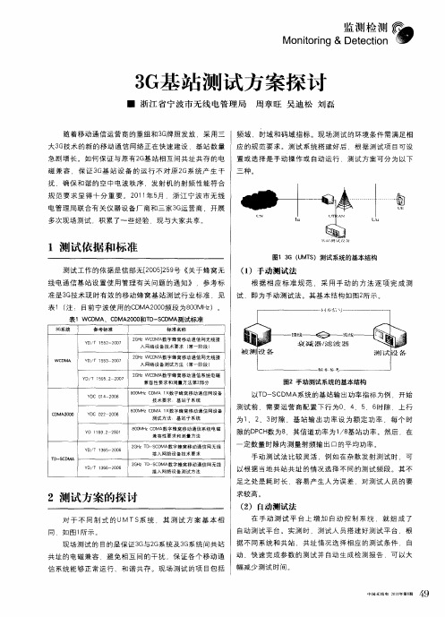
Y / 3 0 7 D T 1 5 2 0 5
2 H D 数宇蜂窝移动通信婀无线接 G z WC MA
八网络设 备测试 方法 ( 第一阶段 )
Y / 5 2 2 0 2 H D 数字蜂窝移动通信系统电磁 D T 19 0 7 5 G z WC MA 兼容性要求和测量方法第2 部分
Y C 0 2 ∞8 D 2 2
8 0 H D A 1 数字蜂 窝移 动通信 网设备 0M zC M × 测试方法 基站子 系统 8 0 z C M 数字蜂 窝移动通信 系统 电磁 0 MH D A 兼容性要求和测量 方法 2 H D S D 数字蜂窝移动通信网无线 G zT - C MA 接 入 网络 设 备 技 术 要 求 2 H D S D 数字蜂窝移动通信网无线 G zT — C MA 接 入 网络 设 备 测 试 方 法
监 测 检 测
Mont ig & De e t i n or tci on
3 基 站 测试 方 案 探 讨 G
■ 浙 江 省 宁 波市 无 线 电 管理 局 周章 旺 吴 迪 松 刘 磊
随 着 移 动 通 信 运 营 商 的 重 组 和 3 牌 照发 放 ,采 用 三 频 域 、 时 域 和 码 域 指 标 。 现 场 测 试 的环 境 条 件 需 满 足 相 G 大3 技 术 的 新 的 移 动 通 信 网络 正 在 快 速 建 设 ,基 站 数 量 应 的规 范 要 求 。 测 试 系统 搭 建 好 后 ,根 据 测 试 项 目可 设 G 急剧 增 长 。 如 何 保 证 与原 有 2 基 站 相 互 间共 址 共 存 的 电 置 或 选 择 是 手 动 操 作 或 自动 运 行 测 试 方 案 可 分 为 以 下 G 磁 兼 容 ,保 证 3 基 站 设 备 的 运 行 不 对 原 2 系 统 产 生 干 三 种 。 G G 扰 确 保 和 谐 的 空 中 电 波 秩 序 ,发 射 机 的射 频 性 能 符 合 规 范 要 求显 得 十 分 重 要 。 2 1 年 5 ,浙 江 宁 波 市 无 线 0 1 月 电 管 理 局 联 合 有 关 仪 器 设 备 厂 商 和 三 家 3 运 营商 ,开 展 G
关于第三代移动通信基站和网络测试解决方案
关于第三代移动通信基站和网络测试解决方案一、基站综合测试仪网络运行质量不仅影响客户的满意度、而且关系到运营成本问题,最终直接影响运行维护商的利润。
所以网络维护工作的好坏,是留住客户并谋取最大利润的关键因素。
实际操作中,网络维护成本和网络运行质量之间,往往是鱼与熊掌不可兼得。
Aeroflex推出的3G基站测试解决方案,可以帮助运行维护商在大幅度降低运行维护成本的同时,高效率高水平的提高网络运行质量;从而很好的解决了网络维护成本和网络运行质量两者之间的矛盾。
全面而高效的测试能力从根本上帮助运行维护商提高工作效率、建立完善的故障检测体系、并且降低了针对同样的问题进行重复劳动的可能性。
该测试解决方案便于操作,检测速度快,极大地提高了现场技术人员的工作效率。
不过如果基站运行错误,那么实际的覆盖范围会小一些,也就是里面圆圈所表示的区域。
这就意味着在灰色区域中的用户可能会出现掉话现象,甚至失去有效信号。
这种情况至少也会降低网络性能和效率。
所有CDMA系统都存在小区呼吸效应。
小区呼吸效应增加了网络维护工作的难度和复杂度,而有效的管理小区呼吸效应是确保实际的覆盖范围和规划的覆盖范围保持一致的关键。
人们经常忽略基站接收机对整个网络运行质量的影响。
如果接收机的灵敏度低于规定指标,那么对更多远程移动终端的信号进行解调操作的难度就会增加。
如果灵敏度较差,那么随着通信等级的提升,小区呼吸效应的影响会更加明显。
还可以从另一个角度看基站接收机运行是否良好对整个网络运行质量的影响。
在第3代技术中,发射机和接收机的运行是密切相关的。
接收机如果出现任何问题,都可能影响到发射机的运行性能。
如果基站的接收机不够敏感,会出现一些调整,比如说,功能控制环路会使每个移动终端增加输出功率,以便为上行链路保持目标误码率。
因为每个移动终端都可视为所有其它移动终端的干涉源,而多重接入系统通过在代码域内共享功率来完成操作,所以会降低上行链路的能量,从而使所有用户的网络性能下降。
无线网络测试

无线网络测试一、引言随着移动互联网应用的广泛普及,无线网络已经成为人们使用互联网的主要方式之一。
无线网络包括移动通信网络和无线局域网两种类型,它们将我们的生活变得更加便利。
但是,网络的稳定性和速度也成为人们非常关心的问题。
在这种情况下,进行无线网络测试就显得非常重要。
本文将从无线网络测试的基本原理、测试方法、测试指标以及测试工具等方面进行讲解,希望能够为广大用户提供一个全面的无线网络测试指南。
二、无线网络测试的基本原理无线网络测试是对无线网络中传输速率、延迟、数据包丢失率等各个方面进行测试的过程。
其中,无线网络测试设备包括测试手机、测试仪器等。
在实际测试中,测试手机通常需要配置一定的测试软件,测试仪器则需要支持多种测试功能。
在无线网络测试过程中,用户的数据将通过无线信号传输到基站,再通过有线网络传输到目标服务器。
整个传输过程中,信号衰减、干扰等因素会对数据传输速率、延迟、丢包率等指标产生影响。
三、无线网络测试的方法无线网络测试主要有实测方法和仿真方法两种。
1. 实测方法实测方法是指通过实际测试设备和网络环境来测试无线网络的各项性能指标。
它是最直接、最真实的测试方法,可以反映出网络实际的性能水平。
在进行实测测试时,需要在真实的网络环境下进行测试,这样才能尽可能真实地反映出网络性能指标。
2. 仿真方法仿真方法是指通过软件模拟无线网络环境进行测试的方法。
响应时间、延迟、带宽等参数可以通过软件进行设置和模拟,从而进行测试。
该方法具有模拟环境可控、测试操作简单等优点,但模拟结果可能与实际情况存在误差。
四、无线网络测试的指标无线网络测试主要涉及以下几个指标:1. 传输速率无线网络传输速率是指在单位时间内传输的数据量。
通常用Mbps或Kbps表示。
在测试中,通过下载和上传等操作可以测量出无线网络的传输速率。
2. 延迟延迟是指从发送数据包到接收端收到数据包所需的时间。
通常用ms或us表示。
无线网络的延迟主要由信号传输时间、网络处理时间等因素决定。
3G基站的测试
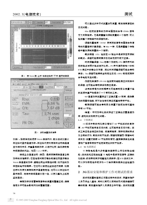
752002.3[电信技术]3G 的出现意味着需要测试更多的基站、检查新的更加复杂的参数,同时出现破坏性干扰的概率也正在不断提高。
由于新的安装项目中共存了多个阶段的2G 、2.5G 和其他无线系统,并且G SM 、T DM A 、cdm aOne 、HSCS D 、G PRS 、E DGE 、EG PRS 、IS -136B/HS 和IS -95B 系统在多年内都有可能同时运行,这样,基站已经成为不能预测的、连续变化的、为不断增长的各种移动设备服务的老技术平台和新技术平台的组合。
在一个基站中,可能会遇到几种蜂窝系统发出的信息及各种来源的干扰,如广播、寻呼和本地网络服务。
小区基站人员必须采用新的BT S (基站)测试战略和工具,以应对这些挑战,并跟上移动通信技术的发展。
迅速、精确的测试对安装时检验BT S 性能及高效诊断可能会中断服务的一系列问题至关重要。
1新的BTS 测试在测试战略中,首先应在BT S 环境的每个阶段评估所有关键的3G 性能参数,包括确定干扰、分析RF 系统中的业务信号、检验T 1电路、保证核心网络可靠的传输能力,下面将更加详细地进行介绍。
3G 系统比以前几代系统要复杂得多,它要求提供更高的数据速率、支持更多的用户、承载更多的业务。
这就要求测试必须灵活,并能够在引入新的性能水平时进一步发展。
同时还必须对其他几种技术和其他类型的BT S 无线系统完成测试。
而用户没有时间或资本对可能遇到的每类信号采用不同的测试仪,因此测试工具必须能够配置,用户只需按一个按键或插入插件模块就可以从一个标准迅速切换到下一个标准。
最重要的是,必须迅速获得适当的解决方案。
因为没有时间处理复杂的仪器控件或试图解释原始数据,所以测试工具必须以清楚、简单、可用的格式显示结果,这样维护人员不需要经过全面的培训。
1.1BTS 无线系统测试跳频系统的性能对无线系统中的功率、时间、调制和波形质量特点依赖性最大。
应确定RF 载波的质量,在码域中进行通道测试。
无线网络测试
无线网络测试无线网络测试是指对无线网络的性能、覆盖范围、信号强度和稳定性等进行评估和优化的过程。
随着移动设备的普及和网络需求的增加,无线网络测试成为了保障网络质量和用户体验的重要环节。
本文将从测试的目的、步骤、常用工具和注意事项等方面介绍无线网络测试的相关内容。
一、测试目的无线网络测试的主要目的是评估无线网络的性能和可用性,发现问题并提供优化建议。
具体而言,无线网络测试的目标包括:1. 评估覆盖范围:测试无线网络的信号强度和覆盖范围,确保在不同区域都能正常连接和使用无线网络。
2. 评估信号强度:测试无线网络的信号强度和稳定性,以确保用户在不同位置都能获得良好的信号质量和数据传输速度。
3. 检测干扰源:通过测试,发现可能对无线网络产生干扰的环境因素或设备,以便采取相应的干扰消除措施。
4. 测试安全性:检测无线网络的安全性,防止未经授权的用户入侵或非法使用无线网络资源。
二、测试步骤无线网络测试可以通过以下步骤进行:1. 规划测试场景:根据实际需求,选择测试地点和测试时间,以保证测试结果的准确性和可靠性。
2. 准备测试设备:选择合适的测试设备,包括无线测试仪、无线网卡、天线等。
确保设备的正常工作和准确的测试数据收集。
3. 进行基础测试:测试无线网络的连接速度、延迟、丢包率等基本指标,并记录测试数据。
4. 进行覆盖测试:在不同区域测试无线网络的信号强度和覆盖范围,如室内、室外、远离基站等。
5. 进行干扰测试:检测周围环境可能存在的干扰源,如电磁波、其他无线网络等,并评估其对无线网络的影响。
6. 进行安全性测试:测试无线网络的安全性,包括密码破解、入侵检测等,确保网络资源的安全可靠。
7. 分析测试结果:根据测试数据和实际需求,对测试结果进行分析和评估,总结问题并提出优化建议。
三、常用工具在无线网络测试中,常用的测试工具包括:1. 无线测试仪:用于收集无线网络的信号强度、速度等相关数据,并进行测试结果的分析和报告的生成。
3G基站发射机性能测试与分析
3G 基站发射机性能测试与分析在当前快速发展的第三代无线通信系统中,为了达到更高的传输率需要采用高度复杂的调制系统,这给工程师带来了新的挑战,本文向中国测试和测量工程师简要介绍了3G 基站发射机需要测试和分析的关键参数及其意义。
在当前快速发展的第三代无线通信系统较之先前的第二代无线网络极大的改善了系统性能和服务质量。
为了达到更高的传输率,3G采用高度复杂的调制系统〃各种3G 基站系统的快速发展对WCDMA 射频部分、码域部分性能稳定运行提出了更高的要求,UMTS 基站系统的维护测量日益要求测量人员进行频域、时域、幅度域、调制域等全方位的性能评估〃这给工程师带来了新的挑战〃WCDMA UMTS Node B 发射机的特征描述包括射频频谱描述和码域解调描述两大部分,基于这种描述的测量可以使用具有解调功能的手持式频谱分析仪进行。
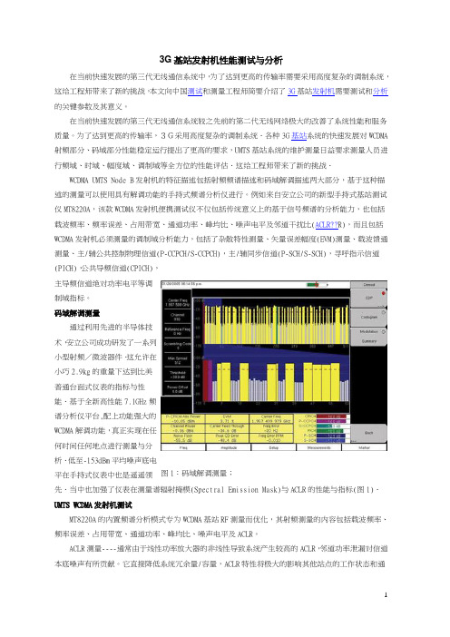
例如来自安立公司的新型手持式基站测试仪MT8220A ,该款WCDMA 发射机便携测试仪不仅包括传统意义上的基于信号频谱的分析能力,也包括载波频率、频率误差、占用带宽、通道功率、峰均比、噪声电平及邻道干扰比(ACLR??R),而且包括WCDMA 发射机必须测量的调制域分析能力,包括了杂散特性测量、矢量误差幅度(EVM)测量、载波馈通测量、主/辅公共控制物理信道(P-CCPCH/S-CCPCH),主/辅同步信道(P-SCH/S-SCH),寻呼指示信道(PICH),公共导频信道(CPICH),主导频信道绝对功率电平等调制域指标。
码域解调测量通过利用先进的半导体技术,安立公司成功研发了一系列小型射频/微波器件〃这允许在小巧2.9kg 的重量下达到比美普通台面式仪表的指标与性能〃基于全新高性能7.1GHz 频谱分析仪平台,配上功能强大的WCDMA 解调功能,真正实现在任何时间任何地点进行测量与分析〃低至-153dBm 平均噪声底电平在手持式仪表中也是遥遥领先〃当中也加强了仪表在测量谱辐射掩模(Spectral Emission Mask)与ACLR 的性能与指标(图1)〃 UMTS WCDMA 发射机测试MT8220A 的内置频谱分析模式专为WCDMA 基站RF 测量而优化,其射频测量的内容包括载波频率、频率误差、占用带宽、通道功率、峰均比、噪声电平及ACLR 。
基站测试规范要求及测试原理概览-WCDMA
4. Set the code domain power of the DPCH under test to Pmax-28 dB by means determined by the manufacturer. The power levels for the other code channels used in step 2 shall remain unchanged
1. BTS transmits Test Model 1 at Pmax. 2. Measure the mean power by MS8609A.
Specification: 2.7dB
4
6.2.2 CPICH Power Accuracy
BTS
B0472 High Power ATT Tx
信道号 = 5 * (FDL – FDL_Offset), FDL_low <= FDL<= FDL_high
3
6.2.1 Base Station Maximum Output Power
BTS
B0472 High Power ATT Tx
ATT
MS2690A
clock
Test Model 1 (Pmax)
工作波段和频率
Operating Band I II III IV V VI VII VIII IX X UL Frequencies UE transmit, Node B receive 1920 – 1980 MHz 1850 –1910 MHz 1710 -1785 MHz 1710 -1755MHz 824 - 849MHz 830 - 840 MHz 2500 - 2570 MHz 880 – 915 MHz 1749.9 - 1784.9 MHz 1710 – 1770 MHz DL frequencies UE receive, Node B transmit 2110 – 2170 MHz 1930 – 1990 MHz 1805 - 1880 MHz 2110 - 2155MHz 869 - 894MHz 875 - 885 MHz 2620 - 2690 MHz 925 – 960 MHz 1844.9 - 1879.9 MHz 2110 – 2170 MHz
3G基站TS 25.141 FSIQ和SMIQ测试

Products: FSIQ, SMIQTests on 3G-Base Stations to TS 25.141with FSIQ and SMIQThis application note describes how to measure the various WCDMA signals which are used for transmitter tests on FDD base stations with an FSIQ signal analyzer, and how to generate the diverse stimulus signals needed for receiver and performance tests with an SMIQ signal generator.The demo program 3GdemoBS is included. Run 3GDemoBS to set up the instruments and carry out the tests to TS 25.141 via remote control. The demo program is distributed as source code; adopt the remote control commands and test sequences for your own test routines, and integrate FSIQ and SMIQ into yourtest systems with maximum ease.Contents1Overview (4)2Installing of the demo program 3GDemoBS (5)3Principles of Operation (6)First steps with the demo program (6)Advanced information about the demo program (8)Uncertainty of the complete test system (9)4 (9)5 (9)6Transmitter Tests (10)Test set up for transmitter tests (11)Transmitter tests step by step (12)Base station maximum output power (6.2.1) (13)CPICH power accuracy (6.2.2) (14)Frequency error (6.3) (17)Power control steps (6.4.2) (19)Power control dynamic range (6.4.3) (21)Total power dynamic range (6.4.4) (23)Occupied bandwidth (6.5.1) (25)Spectrum emission mask (6.5.2.1) (27)Adjacent Channel Leakage Power Ratio (6.5.2.2) (29)Spurious emissions (6.5.3) (31)Spurious emissions Category A (6.5.3.4.1) (32)Spurious emmisions Category B (6.5.3.4.2) (33)Protection of the base station receiver (6.5.3.4.3) (33)Co-existence with GSM 900 (6.5.3.4.4) (34)Co-existence with DCS 1800 (6.5.3.4.5) (34)Co-existence with PHS (6.5.3.4.6) (35)Co-existence with services in adjacent bands (6.5.3.4.7) (35)Co-existence with UTRA-TDD (6.5.3.4.8) (36)Transmit intermodulation (6.6) (36)Error Vector Magnitude (6.7.1) (37)Peak Code Domain Error (6.7.2) (39)7Receiver Tests (41)Test Setup for Receiver tests (41)Receiver Test Demonstration Step by Step (42)Reference Sensitivity Level (7.2) (43)Dynamic Range (7.3) (45)Adjacent Channel Selectivity (7.4) (46)Blocking Characteristics (7.5) (48)Intermodulation Characteristics (7.6) (49)Spurious Emissions (7.7) (51)Verification of Internal BER Calculation (7.8) (53)8PerformanceTests (53)Test Setup for Performance Tests (54)Performance Test Demonstration Step by Step (55)Demodulation of DCH in Static Propagation Conditions (8.2) (55)Demodulation of DCH in Multipath Fading Conditions (8.3) (57)Demodulation of DCH in Moving Propagation Conditions (8.4) (60)Demodulation of DCH in Birth / Death Conditions (8.5) (61)Verification of Internal BLER Calculation (8.6) (62)9Test Signals Only (63)Synchronising Base Station and SMIQ (64)Generating Test Signals (64)10Literature (65)11Abbreviations (66)12Hardware and Software Requirements (67)3GDemoBS Hardware Requirements for PC (67)3GDemoBS Software Requirements for PC (67)Options required for FSIQ and SMIQ (67)13Ordering information (70)14Contact (70)1OverviewThis application note describes how to measure the various WCDMAsignals which are used for transmitter tests on FDD base stations with anFSIQ signal analyzer, and how to generate the diverse stimulus signalsneeded for receiver and performance tests with an SMIQ signal generator.The demo program 3GdemoBS is included. Run 3GDemoBS to set up theinstruments and carry out the tests to TS 25.141 via remote control.Figure 1 shows the basic test set up for this application note:Fig. 1: Basic test set upThe combination of SMIQ and FSIQ can run every test that the specificationTS 25.141 stipulates. Some tests, however, need two SMIQ generators, oradditional signal sources for interference. For these cases, the program3GDemoBS demonstrates the principle of the tests, and generates thesingle signals subsequently.The program 3GDemoBS can also set up the SMIQ to provide any type oftest model and uplink reference measurement channel without running atest.Demo Mode:If there is no base station available, simulate the downlink signal with SMIQ.For receiver and performance tests, monitor the uplink test signal withFSIQ. Both tasks are supported by 3GDemoBS automatically.The demo program is distributed as source code; adopt the remote controlcommands and test sequences for your own test routines, and integrateFSIQ and SMIQ into your test systems with maximum ease.To modify the code and generate a version of your own, you need theLabWindows CVI software from National Instruments Rev. 5.5 or higher.The following pages describe how to use the 3GDemoBS demo programand give a detailed description of each transmitter, receiver andperformance test.Notes:For 3GPP base stations, Rohde & Schwarz offers theTS9850 Test System, for measurements at the air interfaceCMU200 / 300 Universal Radio Communication Tester, seesection Ordering Information.An overview of the application notes currently available for3GPP from Rohde & Schwarz is given in section 10 onpage 65.For a list of abbreviations used in this application note, seesection 11 on page 66.2Installing of the demo program 3GDemoBSThe 3GPP tests require some specific hardware and software options inboth the SMIQ generator and FSIQ analyzer.1. Check the hardware and software requirements. See the section 12 onpage 67.2. Install the 3GDemoBS demo program on your computer. You need thefour files:• 3GDemoBS.MSI• DistFile.cap• Setup.ini• Setup.exeDownload the sites from --> products --> Application NotesSearch for 1MA38.If the Microsoft Installer is not yet available at your PC, download itfrom the R&S website containing 1MA38, and install it first.3. Run Setup.exe.4. Follow the instructions of the installation dialog.Note:If the installation program finds an older version of 3GdemoBS onyour computer, it will deinstall this version first. After thedeinstallation, run Setup.exe again to install the new version.3Principles of OperationFirst steps with the demo programFor running transmitter tests, you need the FSIQ analyzer. For receiver andperformance tests with the demo program, you need at least one SMIQgenerator.Note: To navigate through the 3GDemoBS program without anyinstruments connected, continue from step 3.1. Connect the FSIQ analyzer and SMIQ generator to the controller via theIEEE bus.2. Switch the analyzer and the generator on. Wait until initialisation iscompleted.3. Run 3GDemoBS.exe.On program start, the demo program checks whether the FSIQ and SMIQare connected to the IEC/IEEE-bus, and stores the correspondingaddresses. If only one or no instrument is detected, a message is output toindicate that the missing instruments will be simulated.After a program start with both analyzer and generator connected, the userpanel comes up:Fig. 2: 3GDemoBS user panelIn the TEST field above, the type of test (e.g. Transmitter Test), and the testitself (e.g. 6.2.1 Base Station Maximum Output Power) are selected.Clicking Test Help will give you an overview of the test purpose and the method of test.Set instrument parameters in the two fields GENERATOR and ANALYZER. Enter the frequency and level for the generator and analyzer. Three buttons control the program flow, LEDs indicate the instrument status.Tests results are displayed in the RESULTS window on the left.To run a test:1. Prepare and connect the Device Under Test (DUT).2. Select the test from the test list in the TEST field.3. Adjust frequency and level, if necessary, in the parameter field.4. Configure the instruments by clicking the Configure button.5. Start the test by clicking the Start button.6. Check the results in the RESULTS window.Clicking the Configure button sets up both FSIQ and SMIQ completely. If you don't need both instruments, you can disable the program control for the unused device. This speeds up the configuration process considerably. This also applies if you want to make two tests subsequently which need the same generator configuration, for example, configure the generator for the first test, and disable the program control for the generator before you click the Configure button for the second test. This will be described more in detail later.Once the instruments are configured, you can repeat a test by clicking Start again (without a new configuration).Special features:Signal Settings Demo:To run 3GDemoBS program without a base station, SMIQ and FSIQ have to be set up with the output from the generator connected to the input of the analyzer. Activating the checkbox Signal Settings Demo presets the instrument levels so that the test can be easily monitored. Please note that these levels are very different from the levels stipulated by test specification TS 25.141.If you change to another test, click the Configure button to set appropriate new demo levels.For the transmitter test Power Control Steps, the activated checkbox makes the SMIQ simulate the downlink signal of the base station. If the checkbox is deactivated, the SMIQ will generate an uplink signal to control the output power of the DUT.For the uplink signals of chapter Test signals only, an activated Signal Settings Demo checkbox switches the SMIQ to trigger free run and internal10 MHz reference. If deactivated, trigger and reference are set to external to synchronize with the base station.Break:Clicking this button breaks a running test. However, as SMIQ always finishes a current configuration, the break is not necessarily instantaneous. To get familiar with the program, connect the output of your SMIQ generator to the input of your FSIQ analyzer, and run some tests.Advanced information about the demo programRemote control:You can disable the program control for one or both instruments with the remote control checkboxes on the user panel (see Fig. 2). The entry fields for frequency and level disappear.ØFor simulation of the base station tests, the control for FSIQ and SMIQ has to be switched on.ØFor transmitter tests on a base station, switch the remote control of SMIQ off.ØFor BER measurements switch the remote control of FSIQ off.See the sections Transmitter, Receiver, and Performance Tests for more information.Synchronizing SMIQ and FSIQ:If the Configure button is clicked, the connected instruments are reset first. This switches the SMIQ generator to internal reference, whereas the reference setting of the FSIQ analyzer is not affected.To synchronize the generator and the analyzer, connect the 10 MHz ports of the instruments to each other and switch the FSIQ to external reference (Hardkey SETUP, Softkey REFERENCE INT / EXT).Program Version:The version of the demo program, and the version of the test specification (TS 25.141) the program applies to, are shown in the lower left corner of the user panel (Fig. 2).Modifying tests:The demo program is supplied with its source code. It is written using LabWindows CVI. To modify the code and generate a version of your own, you need the LabWindows CVI software from National Instruments (Rev.5.5 or higher).The transmitter tests are contained in the file t_tests.c, the receivertests in the file r_tests.c, the performance tests in the file p_tests.c,and the generation of the test signals in the file test_sigs.c. Edit thesefiles to change or add remote control commands, or to modify the testsequence.For the configuration of the downlink and uplink signals, see the filesignals.c.The other program files control the user interface, the program flow, and theremote control.After code modifications, recompile the program and build a new version.Uncertainty of the complete test systemFor the complete test set up, you need additional components, such aspower attenuators, cables, couplers and filters. Because they all havesome impact on the test results, no PASS / FAIL verdict is given by thedemo program.Note:Enter your external attenuation on the FSIQ analyzer asreference level offset (Hardkey REF, Softkey REF LEVELOFFSET) after the configuration of the instrument.4.Left intentionally free.5.Left intentionally free.6Transmitter TestsTransmitter tests are measurements on the base station downlink signal,the base station transmitter is active. For the downlink, TS 25.141 specifiesfour different test signals, the test models, to make sure that measurementresults from different base stations can be compared.Table 1 gives a summary of the transmitter tests stipulated by TS 25.141.Table 1: Summary of the transmitter testsThe left column of table 1 contains the number of the chapter in the test specification, the right one the test model that has to be used. All of these tests can be made with the FSIQ analyzer.Test set up for transmitter testsFigure 4 shows the general test set up for the transmitter tests.Fig. 4: General test set up for the transmitter testsThe signals from the base station TX port are recorded and analyzed by FSIQ.Both the SMIQ generator and the FSIQ Analyzer are remote controlled by a PC running 3GDemoBS.ØFigure 4 only shows the principle test set up. For the actual measurement system set up for each test, see Appendix B of the test specification TS 25.141.ØInsert an attenuator (with sufficient attenuation) which can cope with the high power applied at the base station TX output. The maximum input power at the FSIQ connector must not exceed + 30 dBm.ØEnter the insertion loss between the base station and the analyzer as a reference level offset on the FSIQ.The analyzer will then display the levels from the RF port of the base station. Either enter the value manually after of the instruments have been configured, or, add the following IEEE command to the config routine of the respective test and recompile the program.For example, for 50 dB ext. attenuation:disp:trace1:y:rlevel:offset50dbAfter this, recompile the program and build a new version.If you simulate the base station with the SMIQ, it provides the required test model.Transmitter tests step by step1. Connect your DUT to the analyzer as described in TS 25.141. Insert anattenuator (with sufficient attenuation) between the base station TX output and the FSIQ analyzer.2. Select the test from the demo program user panel.3. If you do not need the generator, disable the SMIQ’s control in theremote control checkbox. This speeds up the configuration.4. Start the configuration by clicking the Configure button.After clicking the Configure button, the connected instruments are reset. Reset switches the SMIQ to internal reference, whereas the FSIQ’s reference setting will be not affected.If remote control for the SMIQ generator is enabled, extensive calculation of the required test model inside the SMIQ takes place, which can take up to one minute.While configuration of SMIQ or FSIQ is running, the Configured LEDs are yellow. When configuration is completed, the Configured LEDs go green. The instruments are now correctly configured; the RF output of the SMIQ generator is still switched off.5. Enter the insertion loss between the base station and the analyzer as areference level offset on the FSIQ. This can be done manually, or, by adding the following IEEE command to the config routine of the respective test. For example, for a 50dB external attenuationdisp:trace1:y:rlevel:offset50dbDo not forget to recompile the program and build a new executable. 6. Start the selected test by clicking the Start button.Clicking the Start button switches the RF output of the SMIQ generator on and starts the analyzer. When the measurement is completed, results are displayed on the analyzer and in the RESULTS window.While a test is running, the Running LEDs are green. When the measurement is completed, the Running LED of the analyzer goes out and the Idle LED lights.The generator continues running.Notes:For the transmitter tests, no changes of the instrument settings are performed by the demo program after clickingStart. So, you can repeat a measurement by clicking theStart button again without reconfiguring; you can modify thesetting of the instruments manually between two starts, asrequired.If you want to change to another test which still uses thesame test model, to avoid a time consuming recalculationof the test model, disable the remote control of thegenerator before clicking the Configure button.After a test, check whether an underflow or overflow hasoccurred. Both will be indicated on the analyzer’s screen.The input attenuation of the FSIQ is set to auto by default.For best results, adjust it manually to achieve the optimum(rms) mixer level of –12 dBm. (The mixer level equals theinput level minus the input attenuation.)For basic information about the transmitter tests with FSIQ,see the application note 1EF44 [6] available from theRohde & Schwarz website.Base station maximum output power (6.2.1) Maximum output power, Pmax, of the base station is the mean power level per carrier measured at the antenna connector.The test purpose is to verify the accuracy of the maximum output power across the frequency range and under normal and extreme conditions for all transmitters in the base station.ØFor measurements on a base station, disable the remote control of SMIQ from the 3GDemoBS user panel. Insert an attenuator (with sufficient attenuation) which can cope with the high power applied at the base station TX output.ØFor simulation, connect SMIQ output to the input of the FSIQ, and activate Signal Settings Demo on the 3GDemoBS user panel. The level of SMIQ will be set to -20 dBm.Test procedure on a base station:1. Set the DUT to transmit a signal modulated with the channelcombination of test model 1.2. From the 3GDemoBS user panel select test 6.2.1 Base stationmaximum output power.3. Enter Frequency and Levels.4. Configure the test set up by clicking the Configure button.5. When the configuration is completed, enter your external attenuationon the FSIQ analyzer (Hardkey REF, Softkey REF LEVEL OFFSET).6. Start the test by clicking the Start button on the user panel.7. Check results in the RESULTS window.Test results:In normal conditions, the Base station maximum output power shall remain within +2.0 dB and –2.0 dB of the manufacturer's rated output power.In extreme conditions, the Base station maximum output power shall remain within +2.5 dB and –2.5 dB of the manufacturer's rated output power.Fig. 5 shows a measurement result displayed on the analyzer. The power of the testsignal was set to -20 dBm; cables and connectors caused additional loss.Fig. 5: Base station maximum output power: results displayed on theanalyzerCPICH power accuracy (6.2.2)CPICH power accuracy is defined as the maximum deviation between the ordered channel power and the power in that channel measured at the TX antenna interface.The purpose of the test is to verify that the base station under test delivers CPICH power within margins.ØFor measurements on a base station, disable the remote control of SMIQ from the 3GDemoBS user panel. Insert an attenuator (with sufficient attenuation) which can cope with the high power applied at the base station TX output.ØFor simulation, connect SMIQ output to the input of the FSIQ, and activate Signal Settings Demo on the 3GDemoBS user panel. The total output power of SMIQ will be set to -20 dBm. For the test model 2 used here, the levels of CPICH and CCPCH have to be 10 dB lower.Test procedure on a base station:1. Disable inner loop power control at the base station.2.Set up the base station to transmit at maximum total power as specifiedby the supplier.3. Set up the base station to transmit a signal modulated with the channelcombination of test model 2.4. From the 3GDemoBS user panel select test 6.2.2 CPICH poweraccuracy.5. Enter Frequency and Levels.6. Configure the test set up by clicking the Configure button.7. When the configuration is completed, enter your external attenuation onthe FSIQ analyzer (Hardkey REF, Softkey REF LEVEL OFFSET).8. Start the test by clicking the Start button.9. Check results in the RESULTS window.Test results:In normal conditions, the measurement results shall remain within +2.7 dB and –2.7 dB of the manufacturer's rated output power.In extreme conditions, measurement results shall remain within +3.2 dB and –3.2 dB of the manufacturer's rated output power.Fig. 6 shows the result output from the demo program, Fig. 7 the result displayed on the analyzer. The total power of the testsignal was set to -20 dBm. CPICH and CCPCH have to be 10 dB lower; cables and connectors caused additional loss.Fig. 6: CPICH power accuracy: results output from the demo programFig. 7: CPICH power accuracy: results displayed on the analyzerFrequency error (6.3)Frequency error is the measure of the difference between the actual BS transmit frequency and the assigned frequency.ØFor measurements on a base station, disable the remote control of SMIQ from the 3GDemoBS user panel. Insert an attenuator (with sufficient attenuation) which can cope with the high power applied at the base station TX output.ØTo achieve sufficient accuracy to meet the requirements for this test, you need a high precision external reference for FSIQ, such as a Rubidium or a Cesium standard.ØFor simulation, connect SMIQ output to the input of the FSIQ, and activate Signal Settings Demo on the 3GDemoBS user panel.Test procedure on a base station:1. Set up the base station to transmit at a total power of Pmax - 3 dB.2. Set up the base station to transmit a signal modulated with the channelcombination of test model 4.3. Connect a high precision external reference to FSIQ.4. Set FSIQ to external reference (Hardkey SETUP, SoftkeyREFERENCE INT / EXT).5. From the 3GDemoBS user panel select test6.3 Frequency error.6. Enter Frequency and Levels.7. Configure the test set up by clicking the Configure button.8. Start the test by clicking the Start button.9. Check results in the RESULTS window.10. Repeat the test with total power of Pmax - 18 dB.Test results:The Frequency Error shall be within the range (–0.05 PPM – 12 Hz) to (+0.05 PPM + 12 Hz).Fig. 8 shows the result output from the demo program, Fig. 9 the result displayed on the analyzer.Fig. 8: Frequency error: results output of the demo programFig. 9: Frequency error: results displayed on the analyzerPower control steps (6.4.2)This test measures the power control step and the combined output power change.The power control step is the required step change in the downlink transmitter output power of a code channel in response to the corresponding power control command. The combined output power change is the required total change in the downlink transmitter output power of a code channel in response to multiple consecutive power control commands corresponding to that code channel.For this test, a user equipment simulator or uplink generator has to set and send alternating TPC bits in the uplink signal to the base station to control the power of the downlink signal for one channel. The FSIQ as a code domain analyzer evaluates the power changes versus time.With 3GDemoBS, the setting of the checkbox Signal Settings Demo defines whether the SMIQ shall play either the role of the uplink generator, or simulate the downlink signal of a base station.ØTo simulate the downlink signal, activate the checkbox Signal Settings Demo.ØTo generate the uplink signal, deactivate the checkbox Signal Settings Demo.SMIQ generating an uplink signal:The slot and frame timing of the uplink signal must be fitted to the slot and frame timing of the base station playing the role of a master, and providing trigger and 10 MHz reference signals for the SMIQ generator.A suitable trigger is for example a signal indicating the Super Frame Number (SFN) restart which is output by most of the base stations. A trigger input for the SFN signal is available at the PAR DATA connector on the rear panel of the SMIQ generator.Use an SMIQ-Z5 adapter which provides BNC connectors for all pins of the PAR DATA connector.1. Connect the 10 MHz reference signal of the base station to the REFconnector on SMIQ’s rear panel.2. Connect the SFN restart signal of the base station to the TRIG IN pinof the PAR DATA port.3. Connect FSIQ - inserting an attenuator (with sufficient attenuation) - tothe base station TX port.4. Start base station transmission with channel configuration of test model2.5. Establish downlink power control.6. From the 3GDemoBS user panel select test 6.4.2 Power control steps.7. Disable the checkbox Signal Settings Demo.8. Enter Frequency and Levels.9. Configure the test set up by clicking the Configure button.10. When the configuration is completed, enter your external attenuation onthe FSIQ analyzer (Hardkey REF, Softkey REF LEVEL OFFSET).11. Start the test by clicking the Start button.12. Check the power steps on the analyzer.Note:For further details on synchronizing SMIQ and base station, download the application note 1GP41 [6] from the Rohde &Schwarz website.SMIQ simulating the downlink signal:1. Connect SMIQ output to the input of the FSIQ.2. From the 3GDemoBS user panel select test 6.4.2 Power control steps.3. Activate the checkbox Signal Settings Demo.4. Enter Frequencies.5. Configure the instruments by clicking the Configure button.6. Start the test by clicking the Start button.7. Check power steps on the analyzer.Test results:Test 6.4.2 consists of two parts. Part a) uses alternating TPC bits to check the single power steps, part b) uses 10 consecutive equal steps to measure the combined output tolerance.Fig.10 shows the result output of 3GDemoBS for 10 1dB-steps, Fig. 11 the result displayed on the analyzer.Fig. 10: Power control steps: output from the demo programFig. 11: Power control steps: result displayed on the analyzerPower control dynamic range (6.4.3)The power control dynamic range is the difference between the maximum and the minimum transmit output power of one code channel for a specified reference condition. So, this test comprises two measurements.ØFor measurements on a base station, disable the remote control of SMIQ from the 3GDemoBS user panel. Insert an attenuator (with sufficient attenuation) which can cope with the high power applied at the base station TX output.ØFor simulation, connect SMIQ output to the input of the FSIQ, and activate Signal Settings Demo on the 3GDemoBS user panel. The total output power of SMIQ will be set to -20 dBm. The level of the DPCHused here has to be 3 dB lower.Test procedure on a base station:1. Use the channel configuration of Test model2.2. Set the power of the DPCH under test to Pmax -3 dB. Adjust powerlevels for other code channels as necessary.3. From the 3GDemoBS user panel, select test 6.4.3 Power controldynamic range.4. Enter Frequency and Levels.5. Configure the test set up by clicking the Configure button.6. When the configuration is completed, enter your external attenuation onthe FSIQ analyzer (Hardkey REF, SoftkeyREF LEVEL OFFSET).7. Start the test by clicking the Start button.8. Check results in the RESULTS window.9. Set power of the DPCH under test to the minimum value by meansdetermined by the manufacturer. Power levels for other code channels shall remain unchanged.10. Repeat the measurement.Test results:The maximum power shall be Pmax –3.2 dB or greater; the minimum power shall be Pmax –27.8 dB or less.Fig.12 shows the result output from the demo program, Fig. 13 the result displayed on the analyzer. The total power of the testsignal was set to -20 dBm, the DPCH to 3 dB lower. Cables and connectors caused additional loss.Fig. 12: Power control dynamic range: output from the demo program。
移动通信基站设备及网络的测试

移动通信基站设备及网络的测试移动通信基站设备及网络的测试⒈引言⑴背景⑵目的⑶范围⒉测试策略⑴测试目标⑵测试方法和技术⑶测试资源和环境⒊测试准备⑴测试计划⑵测试用例和测试数据⑶测试工具和设备⑷测试团队组织和分工⒋功能测试⑴基本功能测试⒋⑴信号强度和覆盖测试⒋⑵呼叫功能测试⑵特殊功能测试⒋⑴数据传输功能测试⒋⑵位置跟踪和切换功能测试⑶异常情况测试⒋⑴故障处理和恢复测试⒋⑵超负荷处理测试⒌性能测试⑴无线信号参数测试⒌⑴信号覆盖范围测试⒌⑵信号传输速率测试⑵数据传输性能测试⒌⑴带宽测试⒌⑵延迟测试⒍安全性测试⑴用户身份验证测试⑵数据加密和解密测试⑶安全漏洞测试⒎可靠性测试⑴故障恢复测试⑵负载和稳定性测试⒏用户体验测试⑴呼叫质量测试⑵数据传输质量测试⑶网络速度和稳定性测试⒐测试总结和建议⑴测试结果总结⑵测试问题和风险分析⑶改进建议附件:⒈测试用例表⒊测试数据示例法律名词及注释:⒈移动通信基站设备:用于无线信号的发送和接收,提供移动通信服务的设备。
⒉网络:由一组基站设备组成的多个无线通信传输链路所构成的网络。
⒊信号强度:指基站设备发送的无线信号的强度。
⒋覆盖范围:指基站设备无线信号覆盖的区域范围。
⒌呼叫功能:指基站设备提供的呼叫功能,包括拨打方式和接听方式等功能。
⒍数据传输功能:指基站设备提供的数据传输功能,包括短信、彩信、互联网访问等功能。
⒎位置跟踪功能:指基站设备对移动用户位置的跟踪和定位功能。
⒏切换功能:指基站设备在移动用户从一个基站覆盖区域切换到另一个基站覆盖区域时的无缝切换功能。
⒐故障处理和恢复:指基站设备在故障发生时的处理和恢复能力。
⒑超负荷处理:指基站设备在大量用户同时访问时的处理能力。
移动通信基站设备及网络的测试范文精简处理
移动通信基站设备及网络的测试移动通信基站设备及网络的测试1. 引言2. 移动通信基站设备的测试移动通信基站设备的测试是确保其硬件和软件功能正常运行的关键步骤。
这包括对基站设备的物理连接、电源和天线的功能进行检测,以及对设备的信号处理、编码解码和调度等核心功能进行测试。
测试还包括对设备的能耗、传输效率和容量等性能指标进行评估。
常用的移动基站设备测试方法包括传统的测试仪器和虚拟化测试环境。
传统的测试仪器包括频谱分析仪、信号发生器和信号源等,用于对基站设备的无线信号和频谱进行测试。
虚拟化测试环境利用软件定义网络和虚拟设备模拟真实网络环境,进行基站设备的功能和性能测试。
3. 移动通信网络的测试移动通信网络的测试是确保网络的性能和容量满足用户需求的重要步骤。
测试内容包括对网络的覆盖范围、信号强度、呼叫可靠性和数据传输速率等进行评估。
测试还涉及到对网络的拥塞控制、动态频谱分配和移动性管理等关键技术进行验证。
移动通信网络的测试方法包括现场测试和仿真测试。
现场测试利用专业测试设备和工具对实际网络进行测试,包括对基站信号和网络性能的测量。
仿真测试利用模拟软件和工具对网络的性能和容量进行模拟和评估。
4. 移动通信网络的安全测试移动通信网络的安全测试是确保网络的安全性和可信性的关键步骤。
测试内容包括对网络的认证、加密和身份验证等安全机制进行验证,以及对网络的防护、入侵检测和漏洞扫描等关键技术进行测试。
移动通信网络的安全测试方法包括渗透测试和安全审计。
渗透测试是通过模拟攻击和漏洞利用对网络进行测试,以评估网络的安全性。
安全审计是对网络的配置、策略和日志进行分析和审查,以发现潜在的安全威胁和漏洞。
5. 常用的测试工具和技术移动通信基站设备和网络的测试涉及到许多常用的测试工具和技术。
常用的测试工具包括频谱分析仪、信号发生器、网络分析仪和虚拟化测试平台等。
常用的测试技术包括数据包分析、信号测量、频谱分析和网络协议分析等。
常见的测试工具包括Keysight、Anritsu和Rohde & Schwarz 等公司的设备,用于对无线信号和网络性能进行测试。
移动通信基站设备及网络的测试2023简版
移动通信基站设备及网络的移动通信基站设备及网络的1. 简介移动通信基站是移动通信网络的关键设备之一,负责信号的发射、接收,并提供无线网络覆盖。
对于保证移动通信网络的性能稳定和高效运行,需要进行基站设备及网络的。
本文将介绍移动通信基站设备及网络的内容和方法。
2. 内容移动通信基站设备及网络的主要包括以下内容:2.1 信号覆盖信号覆盖是评估基站信号覆盖范围和质量的重要。
通过在不同位置进行,检测信号强度、信号质量等参数,评估基站的覆盖范围和性能。
2.2 信道容量信道容量是评估基站信道资源使用效率的。
通过模拟多用户接入基站,系统的容量,评估基站在高负荷情况下的性能和稳定性。
2.3 话音质量话音质量是评估基站语音通话质量的。
通过模拟通话场景,话音传输的清晰度、延迟、丢包率等参数,评估基站的语音通话质量。
2.4 数据传输数据传输是评估基站数据传输能力的。
通过模拟大规模数据传输场景,基站的数据传输速率、延迟、丢包率等参数,评估基站的数据传输性能。
2.5 干扰分析干扰分析是评估基站干扰抑制能力的。
通过模拟干扰场景,基站对于干扰信号的抑制效果,评估基站的干扰抑制能力。
3. 方法移动通信基站设备及网络的可以采用以下方法:3.1 实地实地是通过在实际场景中进行,获取真实的数据。
人员可以选择不同位置进行,使用专业的仪器进行数据采集和分析,得出结果。
3.2 模拟环境模拟环境是通过搭建基站环境进行,模拟不同的场景。
人员可以使用仿真工具和设备,模拟不同的信号强度、干扰场景等,进行。
3.3 实验室实验室是在控制环境下进行,通过搭建实验室平台进行。
人员可以使用设备模拟基站和用户设备,进行各项。
4. 工具和设备进行移动通信基站设备及网络的时,可以使用以下工具和设备:- 移动通信仪器:如信号发生器、方式等,用于采集数据和分析信号质量等参数。
- 仿真工具:如网络仿真器,用于模拟不同的环境和场景。
- 基站模拟器:用于模拟基站设备,进行实验室。
移动通信基站设备及网络的测试精简版范文
移动通信基站设备及网络的移动通信基站设备及网络的1. 的目的移动通信基站设备及网络的主要是为了确保其按照设计要求正常运行,保证通信质量和网络性能的稳定和可靠。
2. 内容移动通信基站设备及网络的包括但不限于以下内容:基站硬件设备的功能:基站硬件设备各个模块的功能是否正常,包括天线、信号处理单元、收发模块等。
信号质量:基站发出的信号质量,如功率、频谱等是否符合要求。
邻区关系:基站与周围基站的邻区关系是否正确,保证无线资源的合理利用。
数据传输:基站的数据传输性能,包括数据吞吐量、延迟等指标。
故障恢复:基站在故障发生后的恢复能力,如切换到备份系统、自动重启等。
3. 方法移动通信基站设备及网络的可以采用以下方法:实验室:在实验室环境中搭建基站设备及网络,在控制条件下进行各项。
室内:在室内环境中基站设备及网络的覆盖范围、信号强度等指标。
室外:在真实的室外环境中基站设备及网络的覆盖范围、干扰情况等指标。
上网:通过模拟用户上网行为,基站设备及网络的数据传输性能。
4. 工具移动通信基站设备及网络的可以使用以下工具:Spectrum Analyzer:用于信号的频谱特征。
Network Analyzer:用于分析网络的性能和带宽利用率。
Protocol Analyzer:用于监测和分析通信协议的传输过程。
Drive Test Tool:用于在实际场景中网络覆盖范围和信号质量。
Traffic Generator:用于模拟用户上网行为,数据传输性能。
5. 报告移动通信基站设备及网络的结果应编写报告,包括目的、内容、方法、结果和结论等内容。
报告应准确、清晰地描述过程和结果,提出问题和改进建议,并由相关部门核实和批准。
以上就是移动通信基站设备及网络的的基本内容,通过科学的方法和工具,可以确保基站设备及网络的正常运行,提供稳定可靠的通信服务。
无线测试知识点总结

无线测试知识点总结一、无线测试概述无线测试是指对无线通信系统进行测试,以验证其性能、可靠性和安全性。
无线测试通常涉及到测试设备本身、无线网络和应用程序等各方面。
无线测试可以帮助开发者发现问题并解决问题,确保无线通信系统能够稳定运行。
二、无线测试的重要性无线通信系统的发展和普及,使得无线测试变得越来越重要。
无线通信系统的快速发展和技术更新换代,带来了无线通信系统的复杂度和不确定性,因此无线测试显得尤为重要。
无线测试可以确保无线通信系统的可靠性和安全性,保护用户的利益,保障通信系统的正常运行。
三、无线测试的技术要点无线测试技术要点包括:测试环境搭建、测试用例设计、测试设备和工具选择、测试数据分析和测试报告撰写等方面。
1. 测试环境搭建测试环境搭建是无线测试的基础,合理的测试环境可以有效地提高测试效率和测试覆盖率。
测试环境搭建涉及到测试设备的选择和连接、测试场景的模拟以及测试数据的采集和分析等方面。
2. 测试用例设计测试用例设计是无线测试的关键,测试用例设计要充分考虑无线通信系统的特性和用户需求,确保测试覆盖全面、有效。
测试用例设计需要根据不同的无线通信系统和应用场景进行分类和设计,同时要考虑到系统的复杂性和不确定性。
3. 测试设备和工具选择测试设备和工具的选择是无线测试的关键,不同的测试设备和工具有不同的测试功能和性能。
测试设备和工具的选择需要充分考虑无线通信系统的特性和测试要求,同时也要考虑到测试成本和人力成本等方面。
4. 测试数据分析测试数据分析是无线测试的核心,通过分析测试数据可以发现系统的问题和异常,为无线通信系统的优化和改进提供依据。
测试数据分析需要使用一些测试分析工具,同时也需要对测试数据做出合理的解释和推断。
5. 测试报告撰写测试报告撰写是无线测试的结果呈现,测试报告需要清晰、准确地描述测试过程和测试结果,为无线通信系统的优化和改进提供决策支持。
测试报告需要充分考虑无线通信系统的特性和用户需求,同时也要符合相关的测试标准和规范。
移动通信基站设备及网络的测试精简版

移动通信基站设备及网络的测试1. 引言移动通信基站设备是支撑移动通信网络运行的重要组成部分,它们承担着信号传输、数据处理和网络连接等任务。
为了保证移动通信网络的稳定运行和性能优化,需要对移动通信基站设备及网络进行全面的测试。
2. 移动通信基站设备测试2.1 基站设备安全性测试基站设备运行在复杂的环境中,面临一系列安全威胁。
在部署基站设备前,需要进行安全性测试,以确保设备的安全性和防护能力。
安全性测试主要包括以下方面:设备的物理安全:测试设备的防水、防尘、抗震等能力。
设备的网络安全:测试设备的网络接口的安全性,防止网络攻击和未经授权的访问。
设备的软件安全:测试设备的软件系统的安全性,防止恶意软件的攻击和篡改。
2.2 基站设备性能测试基站设备的性能直接影响移动通信网络的质量和用户体验。
需要进行性能测试来评估基站设备的性能参数,包括:信号传输质量:测试设备的信号传输强度、信道容量和覆盖范围等指标。
数据处理能力:测试设备的数据处理速度、吞吐量和响应时间等指标。
时延和抖动:测试设备在处理数据时的延迟和抖动情况,对实时通信的影响。
2.3 基站设备可靠性测试基站设备的可靠性是保证移动通信网络稳定运行的关键。
可靠性测试主要包括以下方面:设备的故障恢复性:测试设备在发生故障时的自动恢复能力。
设备的冗余性和容错性:测试设备的冗余配置和容错能力,确保网络不受单点故障的影响。
设备的可用性:测试设备的可用性,包括设备的可维护性和可升级性。
3. 移动通信网络测试3.1 网络覆盖测试移动通信网络的覆盖范围直接影响到用户的通信质量和体验。
需要进行网络覆盖测试,评估网络信号的强度和覆盖范围。
覆盖测试包括以下内容:无线信号强度测试:测试不同位置的信号强度,评估信号的衰减情况。
信号覆盖范围测试:测试信号的覆盖范围,评估网络的扩展能力。
3.2 网络容量测试移动通信网络需要支持大量的用户连接和传输数据。
需要进行网络容量测试,评估网络的容量和传输性能。
3G基站现场无线测试简述
3G 基站现场无线测试简述
3G 基站,无论CDMA2000 1x、EV-DO、WCDMA、还是TD- SCDMA 都采用了更加复杂的无线技术,如码分多址、复杂调制、精确功率
控制等。
TD-SCDMA 还采用了时隙突发和灵活的链路分配,其安装和维护测试工作就更加复杂,需要全新的测试方法与测试工具。
本文以TD-SCDMA
为例来介绍基站现场测试,大部分内容同样适用于其他3G 系统。
对3G 基站进行现场测试的仪表必须具备全面的分析功能,能够分析频域、时域、码域、调制域性能指标。
此外还需要考虑仪表的便携性和坚固性。
安立公司集多年手持式仪表开发的成功经验推出的MS272xB 系列手持
式频谱仪和MT8222A/MT8221B 基站综合测试仪(图1),能充分满足上述测试需要,支持所有2G/3G 制式。
本文所述各项测试均基于上述仪表的功能。
图1 功能强大的基站综合测试仪MT8222A
基于方便合理的原则,应首先使用空中接口测量方式在合适的地点检。
3G无线基础知识讲义

以及144k/s的传输速度。CDMA被认为是第三代移动通信
(3G)技术的首选,目前的标准有WCDMA、CDMA 2000、
TD-SCDMA。
一个重要的提示:了宽/窄带的分水岭数据 问题(骨干网传输速率在2.5Gbyte以上、 接入网传输速率达到1Mbyte的网络定义为 宽带),所以显然所有2G和2.5G的产品和 技术都不是宽带技术,而能称得上宽带技 术的只有3G及其后续技术。据说现在是有 人要跳过3G,直接研究4G,不过具体的细 节就不知道了。
3G支持语音和数据
语音和数据信号在许多重要的方面不同: 语音信号可以错误但不能容忍时延;数据 信号能够允许时延但不能容忍错误。因此, 为数据而优化的网络不适合于传送语音信 号。反之,为语音而优化的网络也不适于 数据信号。WLAN主要用于支持数据信号, 与此形成对比的是,3G网络被设计用于同 时支持语音和数据信号。
3G、WLAN、Bluetooth这三种技术本质上 是互补性的,尽管它们可能在边缘上是竞 争的。
下表是由三种技术之间大致的关系:
可以看到这三种技术存在着某些关联,但差异也是相当明 显的。
WLAN目前得到广泛应用的技术是802.11家族,它是
IEEE在1997年发表的第一个无线局域网标准,而现在媒体
移动用户已经超过5亿,覆盖了1/12的人口,GSM技术在
世界数字移动电话领域所占的比例已经超过70%。由于
GSM相对模拟移动通讯技术是第二代移动通信技术,所以
简称2G。目前,我国拥有2.6亿GSM用户(数据截止5月底,
中国移动GSM用户数量1.9亿,中国联通GSM用户数量0.7
亿),中国移动成为世界第一大GSM运营网络。
系统为主的欧洲厂商,日本公司也或多或少参与其中,包
3G测试小结
一些主要功能 提供MEID号 [移动设备ID/ESN]
配备音频编译的模块
写入紧急拨号号码 [119,110,112等]
*提供频段接入频点 [相当于我们看的 电视节目的频道]
IMSI号码 [相当于网络子系统识别的手机号] 提供网络接入频点 提供紧急呼叫号码 根据IMSI号提供相应的数字服务 [短信/通话/彩信/数据] 存储短信 存储号码
• 蜂窝电话或移动电话是当前最普遍应用的无线通信方式。蜂窝电话覆 盖区通常分为多个小区。每个小区由一个基站发射机覆盖。理论上,小 区的形状为蜂窝状六边形,这也是蜂窝电话名称的来源。当前广泛使用 的移动电话系统标准包括:GSM,CDMA和TDMA。运营商已经开始提供下一 代的3G移动通信服务,其主导标准为EVDOCDMA,TDSCDMA,WCDMA。
• 无线电技术是通过无线电波传播信号的技术。
• 无线电技术的原理在于,导体中电流强弱的改变会产生无 线电波。利用这一现象,通过调制可将信息加载于无线电 波之上。当电波通过空间传播到达收信端,电波引起的电 磁场变化又会在导体中产生电流。 通过解调将信息从电 流变化中提取出来,就达到了信息传递的目的。
无线电的用途
• 蜂窝网络被广泛采用的原因是源于一个数学猜想,正六边形被认为是使用最少个 结点可以覆盖最大面积的图形,出于节约设备构建成本的考虑,正六边形是最好的选择。 这样形成的网络覆盖在一起,形状非常象蜂窝,因此被称作蜂窝网络。
目前主流通讯服务提供上绝大部分采用蜂窝网络。什么是蜂窝网络呢?简单地说,就 是把移动电话的服务区别分为一个个正六边形的子区,每个小区设一个基站。形成了形状 酷似“蜂窝”的结构,因而把这种移动通信方式称为蜂窝移动通信方式。蜂窝网络又可分
无线指标测试范文

无线指标测试范文1.介绍随着无线技术的不断发展,无线设备的性能和功能也不断提升。
无线指标测试是一项评估和验证无线设备性能的重要工作。
通过对无线设备的各项指标进行测试,可以确保设备的性能符合设计要求,并满足用户的需求。
2.测试项目2.2 覆盖范围(Coverage Range):测试无线设备的信号覆盖范围。
通过测试可以评估设备的信号传输距离以及在不同环境下的抗干扰能力。
2.3 连接稳定性(Connection Stability):测试无线设备的连接稳定性,包括信号断连、重连速度以及信号强度变化等。
通过测试可以评估设备在高负荷、高干扰环境下的表现。
2.4 吞吐量(Throughput):测试无线设备在高负荷下的数据吞吐量。
通过测试可以评估设备在多用户同时连接的场景下的性能。
2.5 传输延迟(Latency):测试无线设备的数据传输延迟。
通过测试可以评估设备在实时数据传输场景下的性能,如视频通话、游戏等。
2.6 能耗(Power Consumption):测试无线设备的能耗情况。
通过测试可以评估设备在不同使用场景下的电池寿命以及功耗控制能力。
3.测试方法3.1实际场景测试:将无线设备放置在真实的使用环境中进行测试。
通过测试可以模拟真实使用场景下的性能表现,如家庭、办公室、公共场所等。
3.2实验室测试:在受控的实验室环境中进行测试。
通过测试可以排除外部干扰因素,更精确地评估设备的性能指标。
常用的测试设备包括信号发生器、功率计、频谱分析仪等。
4.测试工具进行无线指标测试需要使用一系列专业的测试工具4.1信号发生器:用于产生不同频率和幅度的信号,模拟不同的无线信号环境。
4.2功率计:用于测量无线设备的发送和接收功率,评估设备的发射功率和灵敏度。
4.3频谱分析仪:用于测量不同频段的无线信号,并分析信号的频率、幅度、带宽等特征。
4.4数据包分析仪:用于捕获和分析无线数据包,评估设备的传输质量和稳定性。
4.5无线基站模拟器:用于模拟无线基站,测试无线设备的连接性能和吞吐量。
- 1、下载文档前请自行甄别文档内容的完整性,平台不提供额外的编辑、内容补充、找答案等附加服务。
- 2、"仅部分预览"的文档,不可在线预览部分如存在完整性等问题,可反馈申请退款(可完整预览的文档不适用该条件!)。
- 3、如文档侵犯您的权益,请联系客服反馈,我们会尽快为您处理(人工客服工作时间:9:00-18:30)。
3G基站现场无线测试简述
3G基站,无论CDMA2000 1x、EV-DO、WCDMA、还是TD-SCDMA都采用了更加复杂的无线技术,如码分多址、复杂调制、精确功率控制等。
TD-SCDMA还采用了时隙突发和灵活的链路分配,其安装和维护测试工作就更加复杂,需要全新的测试方法与测试工具。
本文以TD-SCDMA为例来介绍基站现场测试,大部分内容同样适用于其他3G系统。
对3G基站进行现场测试的仪表必须具备全面的分析功能,能够分析频域、时域、码域、调制域性能指标。
此外还需要考虑仪表的便携性和坚固性。
安立公司集多年手持式仪表开发的成功经验推出的MS272xB系列手持式频谱仪和MT8222A/MT8221B基站综合测试仪(图1),能充分满足上述测试需要,支持所有2G/3G制式。
本文所述各项测试均基于上述仪表的功能。
图1 功能强大的基站综合测试仪MT8222A基于方便合理的原则,应首先使用空中接口测量方式在合适的地点检查基站发射机的信号覆盖和信号质量,争取在空口测试中对基站状态做出准确判断。
如难以判断空口测量结果或需要精确测量发射功率,则需要直接连接基站进行测试。
测试步骤。
图2 3G基站测试步骤为获得稳定可靠的空口测量结果,必须找到合适的测量地点,该地点要求具备较高的导频优势。
一般要求导频优势大于10dB。
下面介绍主要的测试项目和定义。
1 基站覆盖和同频干扰测试图3 基站覆盖和同频干扰测试界面同步码与导频优势:同步码扫描显示了当前位置所有激活的同步码。
多个强同步码会造成同道干扰,要求在95%覆盖区域内,与主同步码信号强度之差在10dB以内的同步码数量不超过3个。
导频优势可以帮助确定合适的空口测量地点,一般要求大于10dB。
下行导频时隙功率:下行导频时隙功率可以检查覆盖情况,测试数据还可以下载到地图软件进行分析。
要求在95%覆盖区域内大于-88dBm。
2 多径测试图4 Ec/Io 和Tau测试界面Ec/Io和Tau这两项空中接口测试项目用来帮助解决覆盖问题,可以同时对6个最强的同步码进行测试。
如果需要进一步的细节,在码域功率测试界面会给出扰码信息。
Ec/Io:测量6个最强基站同步码的信号强度(信干比)。
要求在95%的覆盖区域内大于-2dB。
Tau:表示了基站距测试地点的距离。
要求最强同步码基站距离测试地点最近。
3 射频指标测试图5 信道功率、占用带宽测试界面信道功率决定了小区覆盖面积,1.5dB的功率变化就意味着大约15%的覆盖面积变化。
测试结果与额定值之间的误差不应超过±1.0dB。
应直接连接基站进行信道功率测量,高精度功率计选件可提供±0.16dB的测量精度。
占用带宽测量99%信号功率所占带宽,典型值在1.3~1.6 MHz之间。
超过1.6 MHz则意味着会对相邻频点造成干扰。
4 时隙功率图6 下行空时隙功率、时隙峰均值比测试界面下行空时隙功率测量可以帮助判断基站造成的干扰状况以及对上行信号的自干扰程度,因为这些测量可以反映出基站发射机是否能够充分关闭。
要求测量结果小于-82dBm(直接连接基站测量)。
时隙峰均值比指的是时隙的峰值功率和平均功率的比值。
如果峰均值比太低,则很有可能是放大器压缩了信号,并会由此产生失真。
典型值应该大于6dB。
5 信号质量测试图7 误差矢量幅度(EVM)、峰值码域误差、频率误差、噪声底电平测试界面EVM表示了误差在信号中所占的比例。
测量结果应该小于12.5%(直接连接基站测试)。
峰值码域误差指的是最差码道的误差矢量幅度(以dB表示),该指标用来监测由于信道板问题或者放大器压缩所造成的最严重信号失真情况。
测量结果应小于-28dB(扩频因子为16)。
频率误差用于判断基站载波频率是否精确。
只要测试仪表和GPS时钟同步在一起,就可以在空口上精确测量载波频率误差。
指标要求:大区制基站小于±0.05ppm,小区制基站小于±0.1ppm噪声底电平是通用的码域信号质量测量指标,任何类型的码域调制误差都会升高码域的噪声底电平。
测量结果要求小于-20dB。
本文小结3G网络要求更加全面的基站无线性能测试,测试仪表需要具备上述测量功能才能对3G基站和网络性能进行准确判断。
功能全面的高性能手持式仪表是完成上述测试的最佳工具。
本文仅对3G基站测试进行了简单论述,安立公司还为用户准备了更加全面详细的3G基站测试指南和系统测试解决方案。
