DG406BP25中文资料
ADP-101-G1 通用多功能保护测控装置技术和使用说明书
装置初始操作密码是 001。
序号 1
版本号 V1.00
文档修改摘要 第一版
修改日期 2012-11-05
目录
1 概述 .........................................................................................................................................1 1.1 应用范围 ..........................................................................................................................1 1.2 保护配置和功能 ..............................................................................................................1 1.2.1 保护配置 ...................................................................................................................1 1.2.2 测控功能 ...................................................................................................................1 1.2.3 保护信息功能 ...........................................................................................................1 1.3 性能特征 ..........................................................................................................................2
CD4069中文资料

CD4069中文资料CC4069由六个COS/MOS反相器电路组成。
此器件主要用作通用反相器、即用于不需要中功率TTL驱动和逻辑电平转换的电路中。
838电子CD4069引脚功能图交流测试电路和波形切换时间Absolute Maximum Ratings 绝对最大额定值:DC Supply Voltage 直流供电电压(VDD)-0.5V to +18 VDCInput Voltage输入电压(VIN)-0.5V to VDD +0.5 VDCStorage Temperature Range储存温度范围(TS)-65℃to +150℃Power Dissipation功耗(PD)Dual-In-Line 普通双列封装700 mWSmall Outline 小外形封装500 mWLead Temperature 焊接温度(TL)Soldering, 10 seconds)(焊接10秒)260℃IOLLOW Level OutputCurrent 输出低电平电流 (Note 4) VDD = 5V, VO = 0.4V 0.52 0.44 0.88 0.36 mAVDD = 10V, VO = 0.5V 1.3 1.1 2.25 0.9 VDD = 15V, VO =1.5V3.63.08.82.4IOHHIGH Level OutputCurrent 输出高电平电流 (Note 4) VDD = 5V, VO = 4.6V -0.52 -0.44 -0.88 -0.36 mAVDD = 10V, VO = 9.5V -1.3 -1.1 -2.25 -0.9 VDD = 15V, VO =13.5V -3.6-3.0 -8.8-2.4IINInputCurrent 输入电流 VDD = 15V, VIN = 0V-0.30 -10-5 -0.30 -1.0 μA VDD = 15V, VIN = 15V0.3010-50.301.0AC Electrical Characteristics 交流电气特性:Symbol符号Parameter 参数Conditions 条件 最小 典型 最大Units 单位tPHLor tPLHPropagation Delay Time from Input to Output 输入输出传播延迟时间VDD = 5V 50 90 nsVDD = 10V 30 60 VDD = 15V 25 50 tTHL or tTLH Transition Time 过渡时间 VDD = 5V80 150 ns VDD = 10V 50 100 VDD = 15V40 80 CIN Average Input Capacitance 平均输入电容 Any Gate6 15 pF CPDPower Dissipation Capacitance 功耗电容Any Gate(Note6)12pF精确长延时电路原理如上图所示。
辽宁衬氟截止阀参数

辽宁衬氟截止阀参数
辽宁衬氟截止阀是一种常用的阀门,它的主要作用是控制管道中的流体,防止流体倒流或泄漏。
该阀门采用衬氟材料制成,具有耐腐蚀、耐高温、耐磨损等特点,适用于化工、石油、制药等行业。
以下是辽宁衬氟截止阀的参数:
1. 阀门口径:DN15-DN300
2. 阀门压力等级:PN1.6MPa-PN10MPa
3. 阀门适用温度:-40℃-200℃
4. 阀门材质:铸钢、不锈钢、碳钢等
5. 阀门连接方式:法兰、螺纹、对夹等
6. 阀门结构形式:直通式、角式、倾斜式等
7. 阀门密封材料:PTFE、FEP等
8. 阀门执行机构:手动、电动、气动等
以上是辽宁衬氟截止阀的主要参数,不同的使用场合需要选择不同的
参数。
例如,在高温、高压的环境下,需要选择耐高温、耐压的材质
和密封材料;在化工行业,需要选择耐腐蚀的材质和密封材料。
此外,辽宁衬氟截止阀还具有以下优点:
1. 密封性好:采用PTFE、FEP等材料制成的密封圈,具有良好的密封性能,能够有效防止流体泄漏。
2. 耐腐蚀性强:衬氟材料具有良好的耐腐蚀性能,能够适应各种腐蚀
介质。
3. 耐磨损性好:衬氟材料具有良好的耐磨损性能,能够适应高速流体
的冲刷。
4. 操作方便:阀门执行机构可以选择手动、电动、气动等方式,操作
方便,能够满足不同的使用需求。
总之,辽宁衬氟截止阀是一种性能优良、使用方便的阀门,适用于各
种行业的流体控制。
在选择阀门时,需要根据具体的使用场合和要求,选择合适的参数和材质。
肖特基二极管参数表
肖特基二极管参数表【原创版】目录一、肖特基二极管概述二、肖特基二极管参数表详解三、肖特基二极管的应用场景四、结论正文一、肖特基二极管概述肖特基二极管,又称为肖特基势垒二极管,是一种金属与半导体接触的整流器件。
它具有很高的工作效率和较低的正向电压降。
肖特基二极管广泛应用于整流、限幅、开关和稳压等电路中。
二、肖特基二极管参数表详解肖特基二极管参数表主要包括以下几个方面:1.最大重复峰值反向电压(VRRM):表示二极管能够承受的最大重复峰值反向电压。
例如,MBR10200CT 肖特基二极管的 VRRM 为 200V。
2.最大直流闭锁电压(VDC):表示二极管在最大直流电压下仍能保持导通状态的电压值。
例如,MBR10200CT 肖特基二极管的 VDC 为 200V。
3.最大正向平均整流电流(I(AV)):表示二极管在最大正向电压下能够通过的平均整流电流。
例如,MBR10200CT 肖特基二极管的 I(AV) 为10.0A。
4.最大瞬时正向电压(VF):表示二极管在最大正向电流下对应的正向电压。
例如,MBR10200CT 肖特基二极管的 VF 为 0.92V。
5.额定直流阻断电压下的最大直流反向电流(IR):表示二极管在最大直流阻断电压下能够承受的最大直流反向电流。
例如,MBR10200CT 肖特基二极管的 IR 分别为 0.1mA(TA25)和 20.0mA(TA125)。
6.工作温度和存储温度范围(TJ,TSTG):表示二极管能够正常工作的温度范围和存储温度范围。
例如,MBR10200CT 肖特基二极管的 TJ,TSTG 为 -65to 175。
三、肖特基二极管的应用场景肖特基二极管广泛应用于以下场景:1.整流电路:将交流电转换为直流电,例如在电源电路中。
2.限幅电路:限制信号波形的幅值,例如在音频处理电路中。
3.开关电路:实现开关控制功能,例如在场效应管开关电路中。
4.稳压电路:稳定输出电压,例如在稳压电源电路中。
406补口机说明书

科威技术管道自动爬行器(管道内防腐补口机)GD-BK-406/711-DC使用说明书胜利油田胜利油建公司科威智能技术有限公司目录一、安全注意事项 (2)二、GD系列爬行器简介 (3)三、补口机工作原理及各部组成 (4)四、施工要求、操作程序及注意事项 (7)1管道内防腐补口工艺条件 (7)2补口具体要求 (7)3管内作业操作程序 (8)五、维护与保养 (8)一、在使用本产品前,请您仔细阅读本使用说明书为了安全的使用GD系列管道爬行器,使用者应熟悉的了解设备说明书,请您仔细阅读以下注意事项,由于不遵守该使用及说明书中规定的注意事项,所引起的任何故障和损失均不在厂家的保修范围内。
请妥善保管好文件,如有相关疑问,请与我们的客服人员及时联系。
安全注意事项:•该机务必由合格的技术人员根据制造商的指示和具体工艺的要求负责使用、维修及保养。
•第一次使用前,如设备有明显的损坏,请勿通电,请及时与厂家技术服务人员联系。
•在保养、维修之前应确保拔下蓄电池仓插头。
•请勿尝试自行拆卸机器内部部件,或让无经验、不合格的人员进行维修,可能会严重损坏爬行器并造成人身伤害。
•爬行器仅由授权的技术人员进行维修,且仅应使用原厂配件。
•爬行器在使用和保管过程中应注意防水、防火、防潮、防尘。
•爬行器在管外调试运行时,•人员应远离除锈刷盘和喷杯处,以免除锈钢刷打击及涂料甩出伤人或污染衣服。
•由于管道涂料及稀释剂等对出料管为高腐蚀原料,请使用前仔细观察前端出料管是否可以继续使用。
若不宜继续使用,请及时更换。
•运输及搬运时请注意避免喷杯轴、除锈刷盘、无线天线等地方的碰撞撞击,以免造成变形,影响使用。
•补口机进入管道施工前,应先对管道内进行清理工作,防止机器卡机的现象。
二、GD系列爬行器简介GD-BK系列钢质管道内防腐补口机适用于对钢质管道的内环焊缝区域进行除锈、清理及喷涂常温固化液体涂料,以实现对钢质管道内涂层的内防补口。
采用蓄电池直流供电,更加安全方便,施工距离也更加长远。
冷却工质pg25
冷却工质pg25全文共四篇示例,供读者参考第一篇示例:冷却工质PG25是一种常用的制冷剂,广泛应用于空调、冰箱、冷冻箱等制冷设备中。
它具有良好的热传导性能和稳定的化学性质,能够在广泛的温度范围内工作。
本文将详细介绍冷却工质PG25的特性、用途及其在制冷领域中的应用。
一、冷却工质PG25的特性冷却工质PG25是一种无色无臭的液体,化学名称为聚氧乙烯及聚丙烯醚。
它具有较低的粘度和表面张力,能够快速传导热量,提高制冷效率。
它具有较高的稳定性和化学惰性,不易发生化学反应,能够保持制冷系统的长期稳定运行。
冷却工质PG25的密度适中,易于携带和储存,同时也能够在不同温度下保持稳定的液态状态。
它具有良好的温度控制性能,能够满足不同制冷设备的需求。
冷却工质PG25还具有较高的可再生性,对环境友好,不会对大气层造成污染。
冷却工质PG25主要应用于制冷设备中,如空调、冰箱、冷冻箱等。
它能够有效降低设备的工作温度,提高制冷效率,延长设备的使用寿命。
冷却工质PG25还被广泛用于工业生产中,如化工工艺、医药生产、食品加工等领域。
冷却工质PG25还可以用作传热介质,在工业设备中起到冷却和保护的作用。
它能够有效传导热量,降低设备的温度,防止设备过热损坏。
冷却工质PG25还可以用于温度控制系统中,根据需要实现设备的精确控制。
冷却工质PG25在制冷领域中有着广泛的应用。
它被广泛用于空调系统中,作为制冷剂来实现室内空气的冷却和循环。
冷却工质PG25能够有效降低空调系统的工作温度,提高系统的效率,使室内空气保持舒适的温度。
第二篇示例:冷却工质PG25是一种高效的冷却介质,广泛应用于工业领域中的冷却系统中。
它具有优异的散热性能和稳定的化学性质,能够有效地将热量从工业设备中带走,确保设备正常运行。
PG25是一种聚合物冷却剂,通常与水混合使用。
在冷却系统中,PG25的使用可以降低水的结冰温度,提高冷却效果,延长设备的使用寿命。
PG25具有一定的粘度,使得在冷却系统中能够很好地流动,并且可以有效地吸收和散发热量。
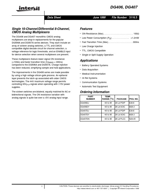
DG406中文资料
CAUTION: Stresses above those listed in “Absolute Maximum Ratings” may cause permanent damage to the device. This is a stress only rating and operation of the device at these or any other conditions above those indicated in the operational sections of this specification is not implied.
NOTES: 1. Signals on SX, DX, EN or AX exceeding V+ or V- are clamped by internal diodes. Limit diode current to maximum current ratings. 2. θJA is measured with the component mounted on an evaluation PC board in free air.
DG406, DG407
DG407 (PLCC) TOP VIEW
DG407 (PDIP, SOIC) TOP VIEW
V+ 1 DB 2 NC 3 S8B 4 S7B 5 S6B 6 S5B 7 S4B 8 S3B 9 S2B 10 S1B 11 GND 12 NC 13 NC 14
28 DA 27 V-
These multiplexers feature lower signal ON resistance (<100Ω) and faster transition time (tTRANS < 300ns) compared to the DG506A and DG507A. Charge injection has been reduced, simplifying sample and hold applications.
高科特实际产品说明书
4
Specifications are subject to change without notice (21.06.2021)
Solid State Relays Accessories, Screw Kits Types SRWKIT…
Ordering Key
Screw Kit Screw size Screw length
0.5 Nm -20° to + 70°C [-4 to +158°F] -40° to + 100°C [-40° to +212°F] DIN EN 50022, 50035
DIN Adaptor for 1-phase SSRs
DIN rail adaptor module for mounting the 1-phase SSR series RA, RD, RM, RS and RAM directly on DIN rail.
Type
UL style 2547 UL style 2464 UL style 2464 UL style 2464 UL style 2464 UL style 2464
Cable size
0.14mm2 0.14mm2 0.14mm2 0.25mm2 0.14mm2 0.14mm2
Termination
- Width x Height x Thickness = 35 x 43 x 0.25 mm
- Packing qty. 50 pcs.
RZHT
- Graphite thermal pad for RZ3 series with adhesive on one side
- Width x Height x Thickness = 70 x 77 x 0.25 mm
zl30406中文资料_数据手册_IC数据表
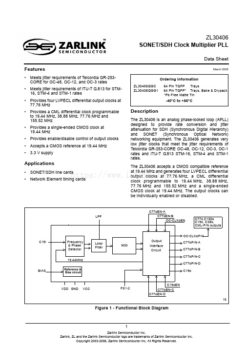
1Features•Meets jitter requirements of Telcordia GR-253-CORE for OC-48, OC-12, and OC-3 rates •Meets jitter requirements of ITU-T G.813 for STM-16, STM-4 and STM-1 rates•Provides four LVPECL differential output clocks at 77.76MHz•Provides a CML differential clock programmable to 19.44MHz, 38.88MHz, 77.76MHz and 155.52MHz•Provides a single-ended CMOS clock at 19.44MHz•Provides enable/disable control of output clocks •Accepts a CMOS reference at 19.44MHz •3.3V supplyApplications•SONET/SDH line cards •Network Element timing cardsDescriptionThe ZL30406 is an analog phase-locked loop (APLL)designed to provide rate conversion and jitter attenuation for SDH (Synchronous Digital Hierarchy)and SONET (Synchronous Optical Network)networking equipment. The ZL30406 generates very low jitter clocks that meet the jitter requirements of Telcordia GR-253-CORE OC-48, OC-12, OC-3, OC-1rates and ITU-T G.813 STM-16, STM-4 and STM-1rates.The ZL30406 accepts a CMOS compatible reference at 19.44MHz and generates four LVPECL differential output clocks at 77.76MHz, a CML differential clock programmable to 19.44MHz, 38.88MHz,77.76MHz and 155.52MHz and a single-ended CMOS clock at 19.44MHz. The output clocks can be individually enabled or disabled.March 2006Ordering InformationZL30406QGC 64 Pin TQFP TraysZL30406QGG164 Pin TQFP*Trays, Bake & Drypack *Pb Free Matte Tin-40°C to +85°CFigure 1 - Functional Block DiagramFrequency Detector VCOC77oP/N-A Interface CircuitLPFFS1-2C77oP/N-B C77oP/N-C VDD GND VCC C77oP/N-D C19oC19oEN OC-CLKoP/NOC-CLKoENC155o CML-P/N outputsLoop FilterC77oEN-C C19iC77o , C19o, C38o, C77oEN-BBIASC77oEN-AC77oEN-D& Phase Output19.44MHz15Reference &Bias circuitZL30406SONET/SDH Clock Multiplier PLLData Sheethttps:///ZL30406Data SheetFigure 2 - TQFP 64 pin (Top View)Change SummaryThe following table captures the changes from the February 2005 issue.Pin DescriptionPage ItemChange1Updated Ordering Information.Pin Description TablePin #Name Description1GND Ground. 0 volt.2VCC1Positive Analog Power Supply. +3.3V ±10%3VCC Positive Analog Power Supply. +3.3V ±10%45OC-CLKoN OC-CLKoP SONET/SDH Clock (CML Output). These outputs provide a programmable differential CML clock at 19.44MHz, 38.88MHz, 77.76MHz and 155.52MHz. The output frequency is selected with FS2 and FS1 pins.6GND Ground. 0 volt7VCC2Positive Analog Power Supply. +3.3V ±10%505254565860626434363840444648423230282624222018GND VDD GND VCC VDD VDD GNDGND NC GND GND NC GND C19o VCC G N D N C C 19o E N F S 1 F S 2 I C N C V D D C 19i V D D N C N C V D D G N D V C C C 77o P -C C 77o N -C G N D V C C C 77o P -B C 77o N -B G N D V C C C 77o P -A C 77o N -A G N D C 77o P -D C 77o N -D V C C 161412106428GND VCC1VCCOC-CLKoN OC-CLKoPGND VCC2LPF C77oEN-B C77oEN-DGND BIASOC-CLKoEN C77oEN-A C77oEN-C GND G N D G N D G N DGND ZL3040665 - EP_GNDhttps:///ZL30406Data Sheet8LPF Low Pass Filter (Analog). Connect to this pin external RC network (R F and C F ) for the low pass filter.9GND Ground. 0 volt 10GND Ground. 0 volt11BIAS Bias. See Figure 11 for the recommended bias circuit.12OC-CLKoENSONET/SDH Clock Enable (CMOS Input). If tied high this control pin enables the OC-CLKoP/N differential driver. Pulling this input low disables the output clock without deactivating differential drivers.13C77oEN-AC77 Clock Output Enable A (CMOS Input). If tied high this control pinenables the C77oP/N-A output clock. Pulling this input low disables the output clock without deactivating differential drivers.14C77oEN-BC77 Clock Output Enable B (CMOS Input). If tied high this control pinenables the C77oP/N-B output clock. Pulling this input low disables the output clock without deactivating differential drivers.15C77oEN-CC77 Clock Output Enable C (CMOS Input). If tied high this control pinenables the C77oP/N-C output clock. Pulling this input low disables the output clock without deactivating differential drivers.16C77oEN-DC77 Clock Output Enable D (CMOS Input). If tied high this control pinenables the C77oP/N-D output clock. Pulling this input low disables the outputclock without deactivating differential drivers.17GND Ground. 0 volt18VDD Positive Digital Power Supply. +3.3V ±10%19NC No internal bonding Connection. Leave unconnected.20NC No internal bonding Connection. Leave unconnected.21NC No internal bonding Connection. Leave unconnected.22VDD Positive Digital Power Supply. +3.3V ±10%23IC Internal Connection. Connect this pin to Ground (GND).2425FS2FS1Frequency Select 2-1 (CMOS Input). These inputs program the clockfrequency on the OC-CLKo output. The possible output frequencies are 19.44MHz (00), 38.88MHz (01), 77.76MHz (10), 155.52MHz (11).26C19oENC19o Output Enable (CMOS Input). If tied high this control pin enables the C19o output clock. Pulling this pin low forces output driver into a high impedance state.27GND Ground. 0 volt28C19i C19 Reference Input (CMOS Input). This pin is a single-ended input reference source used for synchronization. This pin accepts 19.44MHz. 29VDD Positive Digital Power Supply. +3.3V ±10%30GND Ground. 0 volt31NC No internal bonding Connection. Leave unconnected.32GNDGround. 0 volt.Pin Description Table (continued)Pin #Name Descriptionhttps:///ZL30406Data Sheet33GND Ground. 0 volt34VDD Positive Digital Power Supply. +3.3V ±10%35C19o C19 Clock Output (CMOS Output). This pin provides a single-ended CMOS clock at 19.44MHz.36GND Ground. 0 volt37NC No internal bonding Connection. Leave unconnected.38GND Ground. 0 volt 39GND Ground. 0 volt40NC No internal bonding Connection. Leave unconnected.41GND Ground. 0 volt42VDD Positive Digital Power Supply. +3.3V ±10%43GND Ground. 0 volt44VCC Positive Analog Power Supply. +3.3V ±10%45GND Ground. 0 volt46VDD Positive Digital Power Supply. +3.3V ±10%47VCC Positive Analog Power Supply. +3.3V ±10%48GNDGround. 0 volt49VCC Positive Analog Power Supply. +3.3V ±10%.5051C77oN-D C77oP-D C77 Clock Output (LVPECL Output). These outputs provide a differentialLVPECL clock at 77.76MHz. Unused LVPECL port should be left unterminated to decrease supply current.52GND Ground. 0 volt53VCC Positive Analog Power Supply. +3.3V ±10%.5455C77oP-C C77oN-C C77 Clock Output (LVPECL Output). These outputs provide a differential LVPECL clock at 77.76MHz. Unused LVPECL port should be left unterminated to decrease supply current. 56GND Ground. 0 volt57VCC Positive Analog Power Supply. +3.3V ±10%.5859C77oN-B C77oP-B C77 Clock Output (LVPECL Output). These outputs provide a differential LVPECL clock at 77.76MHz. Unused LVPECL port should be left unterminated to decrease supply current.60GND Ground. 0 volt61VCC Positive Analog Power Supply. +3.3V ±10%.6263C77oP-A C77oN-A C77 Clock Output (LVPECL Output). These outputs provide a differential LVPECL clock at 77.76MHz. Unused LVPECL port should be left unterminated to decrease supply current.64GND Ground. 0 volt65EP_GND Exposed die Pad Ground. 0 volt (connect to GND)Pin Description Table (continued)Pin #Name Descriptionhttps:///ZL30406Data Sheet1.0 Functional DescriptionThe ZL30406 is an analog phased-locked loop which provides rate conversion and jitter attenuation for SONET/SDH OC-48/STM-16, OC-12/STM-4 and OC-3/STM-1 applications. A functional block diagram of the ZL30406 is shown in Figure 1 and a brief description is presented in the following sections.1.1 Frequency/Phase DetectorThe Frequency/Phase Detector compares the frequency/phase of the input reference signal with the feedback signal from the Frequency Divider circuit and provides an error signal corresponding to the frequency/phase difference between the two. This error signal is passed to the Loop Filter circuit and averaged to control the VCO frequency.1.2 Loop FilterThe Loop Filter is a low pass filter. This low pass filter ensures that the network jitter requirements are met for an input reference frequency of 19.44MHz. The corner frequency of the Loop Filter is configurable with an external capacitor and resistor connected to the LPF pin and ground as shown below.Figure 3 - External Loop Filter1.3 VCOThe voltage-controlled oscillator (VCO) receives the filtered error signal from the Loop Filter, and based on the voltage of the error signal, generates a primary frequency. The VCO output is connected to the Output Interface Circuit that divides VCO frequency and buffers generated clocks.R F C FInternal Loop FilterZL30406LPFRF=8.2 k Ω, CF=470 nF (for 14 kHz PLL bandwidth)https:///ZL30406Data Sheet1.4 Output Interface CircuitThe output of the VCO is used by the Output Interface Circuit to provide four LVPECL differential clocks at 77.76MHz, one programmable CML differential clock (19.44MHz, 38.88MHz, 77.76MHz, 155.52MHz) controlled with FS1-2 pins and a single-ended 19.44MHz output clock. This block provides also a 19.44MHz feedback clock that closes PLL loop. Each output clock can be enabled or disabled individually with the associated Output Enable pin.To reduce power consumption and achieve the lowest possible intrinsic jitter the unused output clocks must be disabled. If any of the LVPECL outputs are disabled they must be left open without any terminations.The output clock frequency of the OC-CLKo CML differential output clock is selected with FS1-2 pins as shown in the following table.Output Clocks Output Enable PinsC77oP/N-A C77oEN-A C77oP/N-B C77oEN-B C77oP/N-C C77oEN-C C77oP/N-D C77oEN-D OC-CLKoP/NOC-CLKoEN C19oC19oENTable 1 - Output Enable ControlFS2FS1OC-CLKo Frequency 0019.44 MHz 0138.88 MHz 1077.76 MHz 11155.52 MHzTable 2 - OC-CLKo Clock Frequency Selectionhttps:///ZL30406Data Sheet2.0 Applications2.1 Ultra-Low Jitter SONET/SDH Equipment ClocksThe ZL30406 functionality and performance complements the entire family of the Zarlink’s advanced network synchronization PLLs. Its superior jitter filtering characteristics exceed requirements of SONET/SDH optical interfaces operating at OC-48/STM-16 rate (2.5Gbit/s). The ZL30406 in combination with the MT90401 or the ZL30407 (SONET/SDH Network Element PLLs) provides the core building blocks for high quality equipment clocks suitable for network synchronization (see Figure 4).Figure 4 - SONET/SDH Equipment Timing CardMT90401ZL30406OC-CLKo CML38.88 MHz, 19.44 MHz77.76 MHz19.44 MHzC77oA LVPECLC77oB LVPECLC77oC LVPECLC77oD LVPECLC19o CMOSC19iC19o CMOS C155o LVDS C34o/C44o CMOS C16o CMOS C8o CMOS C6o CMOS 19.44 MHz C2o CMOS C1.5o CMOS F8o CMOS F0o CMOS77.76 MHz77.76 MHz77.76 MHz155.52 MHzC4o CMOS 34.368 MHz or 44.736 MHz 16.384 MHz 8.192 MHz 6.312 MHz 4.096 MHz 2.048 MHz 1.544 MHz 8 kHz 8 kHzPRI SECPRIOR SECOR LOCK HOLDOVERRefSel RefAlign R F LPFC FO C -C L K o E N155.52 MHz, 77.76 MHz C 77o E N -AC 77o E N -BC 77o E N -CC 77o E N -DC 19o E ND S C SR /W A 0 - A 6D 0 - D 7uPData PortController PortSynchronization Reference ClocksNote: Only main functional connections are shown20 MHz C 20iF16o CMOS OCXO8 kHz or ZL30407https:///ZL30406Data SheetThe ZL30406 in combination with the MT9046 provides an optimum solution for SONET/SDH line cards (see Figure 5).Figure 5 - SONET/SDH Line CardMT9046ZL30406OC-CLKo CML 38.88 MHz, 19.44 MHz77.76 MHz 19.44 MHzC77oA LVPECLC77oB LVPECL C77oC LVPECL C77oD LVPECL C19o CMOS C19iC19o CMOS C16o CMOS C8o CMOS C6o CMOS 19.44 MHz C2o CMOS C1.5o CMOS F8o CMOS F0o CMOS77.76 MHz 77.76 MHz 77.76 MHzC4o CMOS 16.384 MHz 8.192 MHz 6.312 MHz 4.096 MHz 2.048 MHz 1.544 MHz 8 kHz 8 kHzPRI SECLOCK HOLDOVERRSELR 1LPFC 1O C -C L K o E N155.52 MHz, 77.76 MHzC 77o E N -AC 77o E N -BC 77o E N -CC 77o E N -DC 19o E NM S 1F S 2F L O C K uCSynchronization Reference ClocksNote: Only main functional connections are shown20 MHz F16o CMOS TCXO8 kHz C 2R 1 = 680 ΩC 1 = 820 nF C 2 = 22 nFC20iM S 2F S 1P C C i Hardware ControlT C L Rhttps:///ZL30406Data Sheet2.2 Recommended Interface Circuit 2.2.1 LVPECL to LVPECL InterfaceThe C77oP/N-A, C77oP/N-B, C77oP/N-B, and C77oP/N-D outputs provide differential LVPECL clocks at 77.76MHz. The LVPECL output drivers require a 50Ω termination connected to the VCC-2V source for each output terminal at the terminating end as shown below. The terminating resistors should be placed as close as possible to the LVPECL receiver.Figure 6 - LVPECL to LVPECL Interface2.2.2 CML to CML InterfaceThe CMLP/N output provides a differential CML/LVDS compatible clock at 19.44MHz, 38.88MHz, 77.76MHz,155.52MHz selected with FS1-2 pins. The output drivers require a 50Ω load at the terminating end if the receiver is CML type.Figure 7 - CML to CML InterfaceLVPECL LVPECL ZL30406Z=50 ΩZ=50 ΩC77oP-AC77oN-AReceiverGNDTypical resistor values: R1 = 130Ω, R2 =82ΩR1R2VCC=+3.3 VR1R2VCC0.1 uF+3.3 VDriverZL30406CML Z=50 ΩCML50 ΩOC-CLKoPOC-CLKoNDriverGNDVCCReceiver0.1 uF+3.3 V50 ΩZ=50 Ω0.1 uF0.1 uFLow Impedance DC bias sourcehttps:///ZL30406Data Sheet2.2.3 CML to LVDS InterfaceTo configure the driver as an LVDS driver, external biasing resistors are required to set up the common mode voltage as specified by ANSI/TIA/EIA-644 LVDS standard. The standard specifies the V CM (common mode voltage)as minimum 1.125V, typical 1.2V, and maximum 1.375V. The following figure provides a recommendation for LVDS applications.Figure 8 - LVDS Termination2.2.4 CML to LVPECL InterfaceIn the case when more than four 77.76 MHz clocks are required to drive LVPECL receivers then the unused OC-CLKo clock (CML output) can be configured to output the 77.76 MHz clock and interface to the LVPECL receiver asis shown in the Figure 9. The terminating resistors should be placed as close as possible to the LVPECL receiver.Figure 9 - CML to LVPECL InterfaceZL30406CML Z=50 ΩZ=50 ΩDriver0.1 uF+3.3 VGNDVCCLVDS 10 nF10 nFReceiverR1R2VCC=+3.3 VR1R2100ΩTypical resistor values: R1 = 16 k Ω, R2 = 10 k ΩOC-CLKoPOC-CLKoNLVPECL CML ZL30406Z=50 ΩZ=50 ΩReceiverGNDTypical resistor values: R1 = 82 Ω, R2 =130 ΩR1R2VCC=+3.3 VR1R2VCC0.1 uF+3.3 VDriver10 nF10 nFOC-CLKoPOC-CLKoN77.76MHz https:///ZL30406Data Sheet2.3 Tristating LVPECL OutputsThe ZL30406 has four differential 77.76MHz LVPECL outputs, which can be used to drive four different OC-3/OC-12/OC-48 devices such as framers, mappers and SERDES. In the case where fewer than four clocks are required,a user can disable unused LVPECL outputs on the ZL30406 by pulling the corresponding enable pins low. When disabled, voltage at the both pins of the differential LVPECL output will be pulled up to Vcc - 0.7V.For applications requiring the LVPECL outputs to be in a tri-state mode, external AC coupling capacitors can be used as shown in Figure 10. Typically this might be required in hot swappable applications.Resistors R1 and R2 are required for DC bias of the LVPECL driver. Capacitors C1 and C2 are used as AC coupling capacitors. During disable mode (C77oEN pin pulled low) those capacitors present infinite impedance to the DC signal and to the receiving device this looks like a tristated (High-Z) output. Resistors R3, R4, R5 and R6are used to terminate the transmission line with 50 ohm impedance and to generate DC bias voltage for the LVPECL receiver. If the LVPECL receiver has an integrated 50 ohm termination and bias source, resistors R3, R4,R5 and R6 should not be populated.Figure 10 - Tristatable LVPECL OutputsZ=50Z=50C77oENZL304060.1 uC10.1 uC2R482.5R682.5R5127R3127R1200R22003.3 V 3.3 V https:///ZL30406Data Sheet 2.4 Power Supply and BIAS Circuit Filtering RecommendationsFigure 11 presents a complete filtering arrangement that is recommended for applications requiring maximum jitter performance. The level of required filtering is subject to further optimization and simplification. Please check Zarlink’s web site for updates.Figure 11 - Power Supply and BIAS circuit filteringZL30406Data Sheet3.0 Characteristics†Voltages are with respect to ground unless otherwise stated.‡Exceeding these values may cause permanent damage. Functional operation under these conditions is not implied.†Voltages are with respect to ground unless otherwise stated.‡Typical figures are for design aid only: not guaranteed and not subject to production testing.‡Absolute Maximum Ratings †CharacteristicsSym Min.‡Max.‡Units 1Supply voltage V DDR , V CCRTBD TBD V 2Voltage on any pin V PIN -0.5V CC + 0.5V DD + 0.5V 3Current on any pin I PIN -0.530mA 4ESD Rating V ESD 1500V 5Storage temperature T ST -55125°C 6Package power dissipationP PD1.8WRecommended Operating Conditions †CharacteristicsSym.Min.Typ.‡Max.Units Notes1Operating Temperature T OP -4025+85°C 2Positive SupplyV DD , V CC V CC_VCO3.03.33.6VDC Electrical Characteristics †CharacteristicsSym.Min.Typ.‡Max.Units Notes 1Supply CurrentI DD +I CC140155mALVPECL, CMLdrivers disabled and unterminated 2Incremental Supply Current to single LVPECL driver (driver enabled and terminated, see Figure 6)I LVPECL40mANote 1,23Incremental Supply Current to CML driver (driver enabled and terminated, see Figure 7)I CML24mA Note 34CMOS: High-level input voltageV IH 0.7V DDV DD V 5CMOS: Low-level input voltageV IL 00.3V DDV 6CMOS: Input leakage current, C19iI IL1uAV I = V DD or 0Vhttps:///ZL30406Data Sheet†: Voltages are with respect to ground unless otherwise stated.‡:Typical figures are for design aid only: not guaranteed and not subject to production testing.Note:Supply voltage and operating temperature are as per Recommended Operating ConditionsNote 1:The I LVPECL current is determined by termination network connected to LVPECL outputs. More than 25% of this current flowsoutside the chip and it does not contribute to the internal power dissipation. Note 2:LVPECL outputs terminated with Z T = 50Ω resistors biased to V CC -2V (see Figure 6)Note 3:CML outputs terminated with Z T = 50Ω resistors connected to low impedance DC bias voltage source (see Figure 7)7CMOS: Input bias current for pulled-down inputs: FS1, FS2, C77oEN-A, C77oEN-C, C77oEN-D, OC-CLKoEN I B-PU300uAV I = V DD8CMOS: Input bias current for pulled-up inputs: , C77oEN-B, C19o_ENI B-PD90uAV I = 0V9CMOS: High-level output voltageV OH 2.4V I OH = 8 mA 10CMOS: Low-level output voltageV OL 0.4V I OL = 4 mA 11CMOS: C19o output rise time (18pF)T R 1.8 3.3ns 18 pF load 12CMOS: C19o output fall time (18pF)T F1.1 1.4ns 18 pF load 13LVPECL: Differential output voltageIV OD_LVPECL I 1.30V Note 214LVPECL: Offset voltageV OS_LVPECLVcc-1.38Vcc-1.27Vcc-1.15V Note 215LVPECL: Output rise/fall times T RF 260ps Note 216CML: Differential output voltageIV OD_CML I 0.70V Note 317CML: Offset voltage (Also referred to as common mode voltage)V OS_CMLVcc-0.58Vcc-0.54Vcc-0.50VNote 318CML: Output rise/fall timesT RF120ps Note 3DC Electrical Characteristics † (continued)CharacteristicsSym.Min.Typ.‡Max.Units Notes https:///ZL30406Data SheetFigure 12 - Output Timing Parameter Measurement Voltage Levels† Supply voltage and operating temperature are as per Recommended Operating Conditions.‡Typical figures are for design aid only: not guaranteed and not subject to production testing.Figure 13 - C19i Input to C19o and C77o Output TimingAC Electrical Characteristics †- Output Timing Parameters Measurement Voltage LevelsCharacteristicsSym CMOS ‡LVPECL CMLUnits 1Threshold VoltageV T-CMOS V T-LVPECL V T-CML0.5V DD0.5V OD_LVPECL0.5V OD_CMLV2Rise and Fall Threshold Voltage High V HM 0.7V DD 0.8V OD_LVPECL 0.8V OD_CML V 3Rise and Fall Threshold Voltage LowV LM0.3V DD0.2V OD_LVPECL0.2V OD_CMLVAC Electrical Characteristics †- C19i Input to C19o and C77o Output TimingCharacteristicsSym.Min.Typ.‡Max.Units Notes1C19i to C19o delay t C19D 6.7ns 2C19i to C77oA delayt C77D-4nsV T All SignalsV HM V LMt IF , t OFt IR , t ORTiming Reference Pointshttps:///ZL30406Data Sheet AC Electrical Characteristics† - C19i Input to OC-CLKo Output Delay Timing (CML)Characteristics Sym.Min.Typ.‡Max.Units Notes1C19i to OC-CLKo(19) delay t OC-CLK19D 3.2ns2C19i to OC-CLKo(38) delay t OC-CLK38D 3.0ns3C19i to OC-CLKo(77) delay t OC-CLK77D 2.7ns4C19i to OC-CLKo(155) delay t OC-CLK155D 2.4ns† Supply voltage and operating temperature are as per Recommended Operating Conditions.‡Typical figures are for design aid only: not guaranteed and not subject to production testing.Figure 14 - C19i Input to OC-CLKo Output TimingZL30406Data SheetAC Electrical Characteristics†- C77 Clocks Output TimingCharacteristics Sym.Min.Typ.‡Max.Units Notes 1C77oA to C77oB t C77D-AB100ps2C77oA to C77oC t C77D-AC100ps3C77oA to C77oD t C77D-AD100ps† Supply voltage and operating temperature are as per Recommended Operating Conditions.‡Typical figures are for design aid only: not guaranteed and not subject to production testing.Figure 15 - C77oB, C77oC, C77oD Outputs TimingZL30406Data SheetPerformance Characteristics - Functional- (V CC = 3.3V ±10%; T A = -40 to 85°C )†Typical figures are for design aid only: not guaranteed and not subject to production testing.‡Loop Filter components: R F =8.2 k Ω, C F =470 nF†Typical figures are for design aid only: not guaranteed and not subject to production testing.‡Loop Filter components: R F =8.2 k Ω, C F =470 nFCharacteristicsMin.Max.Units Notes1Pull-in range ±1000ppm 2Lock Time300msPerformance Characteristics: Output Jitter Generation - GR-253-CORE conformance - (V CC = 3.3V ±10%; T A = -40 to 85°C)GR-253-CORE Jitter Generation Requirements ZL30406 Jitter Generation Performance Interface (CategoryII)JitterMeasurementFilter Limit in UI Equivalent limit in time domainTyp.†Max.‡Units 1OC-48STS-4812kHz - 20MHz0.1 UIpp 40.2-16.9ps P-P 0.01UI RMS 4.02 1.3 2.1ps RMS 2OC-12STS-1212kHz - 5MHz0.1 UIpp161-9.0ps P-P 0.01UI RMS16.10.71.3ps RMSPerformance Characteristics: Output Jitter Generation - ETSI EN 300 462-7-1 conformance - (V CC = 3.3V ±10%;T A = -40 to 85°C)EN 300 462-7-1 Jitter Generation RequirementsZL30406 Jitter Generation Performance Interface JitterMeasurementFilter Limit in UI Equivalent limit in time domainTyp.†Max.‡Units 1STM-161MHz to 20MHz0.1 UIpp40.2-12.6ps P-P -- 1.0 1.5ps RMS 5kHz to 20MHz0.5UIpp201-17.1ps P-P -- 1.3 2.2ps RMS 2STM-4250kHz to 5MHz0.1 UIpp161- 5.8ps P-P --0.460.9ps RMS 1kHz to 5MHz0.5 UIpp804-29.8ps P-P -- 2.43.2ps RMShttps:///ZL30406Data Sheet†Typical figures are for design aid only: not guaranteed and not subject to production testing.‡Loop Filter components: R F =8.2 k Ω, C F =470 nFPerformance Characteristics: Output Jitter Generation - G.813 conformance (Option 1 and 2) - (V CC = 3.3V±10%; T A = -40 to 85°C)G.813 Jitter Generation RequirementsZL30406 Jitter Generation PerformanceInterfaceJitterMeasurementFilter Limit in UIEquivalent limit in time domainTyp.†Max.‡UnitsOption 11STM-161MHz to 20MHz0.1 UIpp40.2-12.6ps P-P -- 1.0 1.5ps RMS 5kHz to 20MHz0.5 UIpp201-17.1ps P-P -- 1.3 2.2ps RMS 2STM-4250kHz to 5MHz0.1 UIpp161- 5.8ps P-P --0.460.9ps RMS 1kHz to 5MHz0.5 UIpp804-29.8ps P-P --2.43.2ps RMS Option 23STM-1612kHz - 20MHz0.1 UIpp 40.2-16.9ps P-P -- 1.32.1ps RMS 4STM-412kHz - 5MHz0.1 UIpp161-9.0ps P-P --0.71.3ps RMShttps:///。
乐泰各类胶粘剂型号及简介

单液 黑色,高可靠性,高Glob的EO-1060,低CTE值
EO-1060
单液 黑色比EO-1016更低的离子含量和CTE值,填加了calcium carbonate ,适合固化後的打磨。
抗冲击性能好,抗剥离强度高,能填充间隙
4201耐热型
橡胶增加型,中等粘度,耐冲击,耐高温(120℃),热老化强度是普通的10倍
414塑料粘接型
耐湿性,耐候性好。用于粘接塑料。
415金属粘接型
高粘度,抗冲击性能好。用于粘接金属。
454表面不敏感型
通用型,高粘度。用于惰性表面,粘接多孔、酸性及吸收性的材料。
是大间隙填充理想的用胶。它是一种结构胶,能提供环氧树脂的强度、瞬干胶的固化速度。
在几分钟内固化。特别的配方耐溶剂性能好
用于粘接刚性材料,如将铁氧体粘到电机的电镀金属件或扬声器零件上,也适于粘接金属和玻璃,配用促进剂7649。
326快速固化
它是一种高强度多用途粘接剂,一种能提供环氧树脂的强度以及瞬干胶的固化速度的结构胶。耐溶剂性好。
乐
泰
结
构
胶
乐泰厌氧结构胶具有环氧胶的强度,瞬干胶的固化速度。对金属,塑料,磁材料有广泛粘接性能。应用于电机,变压器,发动机等众多领域
低粘度,流动性较好,快速固化,配用促进剂7649。
319通用型
具有耐溶性,适合用于粘接刚性材料如金属、玻璃和某些塑料。
坚固、柔韧、耐冲击强度高
324耐冲击
需用于粘接表平材料(flat parts),配用促进剂7075
乐泰各类胶粘剂型号及简介
乐
泰
瞬
干
胶
乐泰瞬干胶在工业上得到了最广泛的应用。乐泰瞬干胶涵盖了各种粘度,不同固化速度。充分适应各种充间隙及与被粘接材料。
cd4069中文资料_数据手册_参数

NS 14 2000 Green (RoHS & no Sb/Br)
CU NIPDAU
Level-1-260C-UNLIM -55 to 125
NS 14 2000 Green (RoHS & no Sb/Br)
CU NIPDAU
Level-1-260C-UNLIM -55 to 125
PW
14
90 Green (RoHS
(5) Multiple Device Markings will be inside parentheses. Only one Device Marking contained in parentheses and separated by a "~" will appear on a device. If a line is indented then it is a continuation of the previous line and the two combined represent the entire Device Marking for that device.
ACTIVE TSSOP
ACTIVE
CDIP
D
14
50 Green (RoHS
& no Sb/Br)
CU NIPDAU
Level-1-260C-UNLIM -55 to 125
D
14 2500 Green (RoHS CU NIPDAU | CU SN Level-1-260C-UNLIM -55 to 125
Copyright 2003, Texas Instruments Incorporated
PACKAGE OPTION ADDENDUM
ADG406中文资料
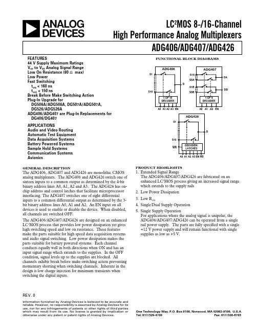
APPLICATIONS Audio and Video Routing Automatic Test Equipment Data Acquisition Systems Battery Powered Systems Sample Hold Systems Communication Systems Avionics
VIN = 0 or VDD f = 1 MHz
RL = 300 Ω, CL = 35 pF; V1 = ± 10 V, V2 = ϯ10 V; Test Circuit 5 RL = 300 Ω, CL = 35 pF; VS = +5 V, Test Circuit 6 RL = 300 Ω, CL = 35 pF; VS = +5 V, Test Circuit 7 RL = 300 Ω, CL = 35 pF; VS = +5 V, Test Circuit 7
Test Conditions/Comments
ANALOG SWITCH Analog Signal Range RON
RON Match
LEAKAGE CURRENTS Source OFF Leakage IS (OFF) Drain OFF Leakage ID (OFF) ADG406, ADG426 ADG407 Channel ON Leakage ID, IS (ON) ADG406, ADG426 ADG407
DG系列使用说明书
DG系列大钩使用说明书兰州兰石国民油井石油工程有限公司2005年1月目 录前言1. 技术规范 (1)2. 结构说明 (1)3. 使用与维护保养 (2)4. 润滑 (3)5. 运输﹑保管 (3)6. 附表 (3)7. 附图 (4)图1 DG大钩图2 制动装置前 言DG大钩是石油钻机的提升设备之一,它和游车一起构成钻机提升系统的可动部分。
在钻井作业中,主要用于悬吊钻杆柱。
DG大钩能与符合API规范的相同(或相当)级别的游车﹑水龙头配套使用。
为了帮助广大用户对该系列产品的性能特点有所了解,以便正确合理地使用大钩,本说明书对大钩的技术规范﹑结构特点﹑使用及维护保养等分别作了比较详细的介绍。
所以,正确使用本说明书,对延长大钩寿命保证安全可靠性,提高生产效率都有着重要意义。
我公司为用户所需备件提供了大钩的《零件图册》,若用户需要请按大钩《零件图册》选订,并注明图号﹑名称。
每台大钩上均有出厂编号,若用户订购备件或查询有关事宜,必须指明大钩的型号和出厂编号。
厂家有权在任何时候更改大钩的型号或设计而不通知用户也不对用户承担任何义务。
兰州兰石国民油井石油工程有限公司推荐用户使用本公司产品的替换零件,使用非本公司的替换零件会使你的产品性能下降。
兰州兰石国民油井石油工程有限公司1.技术规范表1大钩技术规范2. 结构说明DG大钩的钩身、吊环、吊环座是由特种合金钢铸造而成。
下筒体、钩杆是由合金锻造钢制成,所以该系列大钩有较高的承载能力。
大钩吊环(1)与吊环座(3)用吊环销(2)连接,下筒体(8)与钩身(9)用左旋螺纹连接,并用止动块防止螺纹松动,钩身和筒体可沿钩杆(15)上下运动,筒体和弹簧座(17)内装有青铜衬套(16)和(19),以减少钩杆的磨损。
筒体内装有内﹑外弹簧(7﹑6),起钻时能使立根松扣后向上弹起。
轴承采用推力滚子轴承(18)。
DG大钩是完全按照API SPEC 8A规范设计制造的。
大钩装配好后开有液流通道的弹簧座把钩身和筒体内的空腔分为两部分。
BPG400 真空规管中文手册
IR 090热阴极电离复合真空计使用说明书BG 804 171 BE目录产品标识有效范围使用范围工作原理注册商标1 安全1.1 使用符号1.2 人员素质1.3 一般安全规则1.4 赔偿责任与保修2 技术参数3 安装3.1 真空连接3.1.1 拆卸和安装电子学单元3.1.2 安装延伸件3.2 电源连接3.2.1 与COMBIV AC IT23一起使用3.2.2 与其它测量仪器一起使用4 运行4.1 测量原理,测量特性4.2 真空计工作原理4.3 除气4.4 显示器4.5 RS232C接口4.5.1 功能说明4.5.1.1 IR090输出4.5.1.2 IR090输入5 维护5.1 维护5.2 真空计调整5.3 真空计清洗5.4 安装障板5.5 更换障板5.6 更换规管5.7 故障查找6 拆卸7 产品返修8 附件9 备件10 废物处理附录A. 测量讯号与压强的关系B. 气体种类与压强的关系污染申报表参阅本说明书中的章节,采用符号(→XY)。
参阅其它文献,采用符号(→[Z])。
产品标识与Leybold Inficon联系时,请标明产品标牌上给出的信息。
将信息复制在标牌的复印件上。
有效范围本说明书适用于下列件号的产品不带显示器120 90 (法兰DN 25 ISO-KF)120 92 (法兰DN 40 CF-R)带显示器120 91 (法兰DN 25 ISO-KF)120 94 (法兰DN 40 CF-R)产品的件号在标牌上标明。
本公司保留对说明书不预先通知的技术更改权。
使用范围I R090用于在压强5×10⁻¹⁰…1000毫巴范围内非易燃性气体和气体混合物的真空测量。
真空计规管是SKY Smart真空计规管系列的一个组成部分。
可与COMBIV AC IT23或其它测量仪器一起工作。
工作原理在整个测量范围内,热阴极电离复合真空计有连续的测量特性。
它的测量讯号是对数压强输出。
真空计的功能包括BA规热阴极电离测量系统(用于p<2.0×10⁻²毫巴)和皮拉尼测量系统(用于p>5.5×10⁻³毫巴)。
CB-B 25型 齿轮泵

上海第二工业大学
Shanghai Second Polytechnic University
目录
工业工程系
一. 课题要求 ..............................................................................................................................3 二. 溢流阀的工作原理 ................................................................................................................3 三. 齿轮泵的结构及各零件间的装配关系....................................................................................4 四. 绘制齿轮泵装配图的提示 .....................................................................................................7 五. CB-B 25 型齿轮泵零件明细表 ..............................................................................................7 六. CB-B 25 型齿轮泵的零件图..................................................................................................9
辽宁衬氟截止阀参数

辽宁衬氟截止阀参数
辽宁衬氟截止阀是一种常用的阀门,其主要参数包括以下几个方面:
1. 型号:辽宁衬氟截止阀的型号一般由阀门的规格、连接方式、结构形式等因素决定。
2. 压力等级:辽宁衬氟截止阀的压力等级通常根据介质的工作压力、温度等因素来确定,常见的压力等级包括PN10、PN16、PN25、PN40等。
3. 连接方式:辽宁衬氟截止阀的连接方式有法兰连接、对夹连接、螺纹连接等多种方式。
4. 材质:辽宁衬氟截止阀的主要材质通常包括阀体、阀盖、阀杆等部件的材质,一般选择高强度、耐腐蚀的材料,如碳钢、不锈钢、合金钢等。
5. 温度范围:辽宁衬氟截止阀的适用温度范围一般由阀门的材质、密封材料等因素来决定,一般可适用于-50℃至+200℃的温度范围。
6. 适用介质:辽宁衬氟截止阀适用于酸、碱、盐等腐蚀性介质,如硝酸、氢氟酸、盐酸、氢氧化钠等。
以上是辽宁衬氟截止阀的主要参数介绍,不同型号和规格的阀门参数可能会有所不同,具体选型应根据实际情况来确定。
- 1 -。
DG406DJ+中文资料

DG406DJ+中文资料General DescriptionMaxim’s redesigned DG406 and DG407 CMOS analog multiplexers now feature guaranteed matching between channels (8?, max) and flatness over the specified sig-nal range (9?, max). These low on-resistance muxes (100?, max) conduct equally well in either direction and feature guaranteed low charge injection (15pC, max). In addition, these new muxes offer low input off-leakage current over temperature—less than 5nA at +85°C.The DG406 is a 1 of 16 multiplexer/demultiplexer and the DG407 is a dual 8-channel multiplexer/demultiplex-er. Both muxes operate with a +4.5V to +30V single supply and with ±4.5V to ±20V dual supplies. ESD pro-tection is guaranteed to be greater than 2000V per Method 3015.7 of MIL-STD 883. These improved muxes are pin-compatible plug-in upgrades for the industry standard DG406 and DG407.________________________ApplicationsSample-and-Hold Circuits Test EquipmentGuidance and Control Systems Communications Systems Data-Acquisition Systems Audio Signal Routing____________________________FeaturesPin-Compatible Plug-In Upgrade for Industry Standard DG406/DG407Guaranteed Matching Between Channels, 8?(max)?Guaranteed On-Resistance Flatness, 9?(max)?Guaranteed Low Charge Injection, 15pC (max)?Low On-Resistance 100?(max)?Input Leakage, 5nA (max) at +85°C Low Power Consumption, 1.25mW (max)?Rail-to-Rail SignalHandlingDigital Input Controls TTL/CMOS Compatible ?ESD Protection >2000V per Method 3015.7DG406/DG407Improved, 16-Channel/Dual 8-Channel,CMOS Analog Multiplexers________________________________________________________________ Maxim Integrated Products1_________________Pin Configurations19-4729; Rev 5; 8/04Ordering Information continued at end of data sheet.* Contact factory for dice specifications. Ordering Information_______________Functional DiagramsFor pricing, delivery, and ordering information,please contact Maxim/Dallas Direct!at 1-888-629-4642, or visit Maxim’s website at .D G 406/D G 407Improved, 16-Channel/Dual 8-Channel,CMOS Analog Multiplexers2___________________________________________________________________ ____________________ABSOLUTE MAXIMUM RATINGSELECTRICAL CHARACTERISTICS—Dual Supplies(V+ = 15V, V- = -15V, GND = 0V, V AH = +2.4V, V AL = +0.8V, T A = T MIN to T MAX , unless otherwise noted.)Stresses beyond those listed under “Absolute Maximum Ratings” may cause permanent damage to the device. These are stress ratings only, and functional operation of the device at these or any other conditions beyond those indicated in the operational sections of the specifications is not implied. Exposureto absolute maximum rating conditions for extended periods may affect device reliability.(Voltage Referenced to V-)V+............................................................................-0.3V, 44V GND.........................................................................-0.3V, 25V Digital Inputs, S, D (Note 1)....................(V- - 2V) to (V+ + 2V) or 30mA (whichever occurs first)Continuous Current (any terminal)......................................30mA Peak Current, S or D(pulsed at 1ms, 10% duty cycle max)..........................100mA Continuous Power Dissipation (T A = +70°C)28-Pin Plastic DIP (derate 9.09mW/°C above +70°C)..727mW 28-Pin Wide SO (derate 12.50mW/°C above +70°C)...1000mW 28-Pin PLCC (derate 10.53mW/°C above +70°C)........842mW 28-Pin CERDIP (derate 16.67mW/°C above +70°C)...1333mW 28-Pin TSSOP (derate 12.8mW/°C above +70°C)......1025mW Operating Temperature RangesDG406/DG407C_ ...............................................0°C to +70°C DG406/DG407D_ ............................................-40°C to +85°C DG406/DG407AK..........................................-55°C to +125°C Storage Temperature Range.............................-65°C to +150°C Lead Temperature (soldering, 10s).................................+300°CNote 1:Signals on S_, D_, A0, A1, A2, A3, or EN exceeding V+ or V- are clamped by internal diodes. Limit forward current to max-imum current ratings.DG406/DG407Improved, 16-Channel/Dual 8-Channel,CMOS Analog Multiplexers_______________________________________________________________________________________3ELECTRICAL CHARACTERISTICS—Dual Supplies (continued) (V+ = 15V, V- = -15V, GND = 0V, V AH = +2.4V, V AL = +0.8V, T A = T MIN to T MAX , unless otherwise noted.)D G 406/D G 407Improved, 16-Channel/Dual 8-Channel,CMOS Analog Multiplexers4___________________________________________________________________ ____________________ELECTRICAL CHARACTERISTICS—Single Supply(V+ = 12V, V- = 0V, GND = 0V, V AH = +2.4V, V AL = +0.8V, T A = T MIN to T MAX , unless otherwise noted.)Note 2:The algebraic convention where the most negative value is a minimum and the most positive value a maximum is used inthis data sheet.Note 3:Guaranteed by design.Note 4:?R ON = R ON(MAX)- R ON(MIN).On-resistance match between channels and flatness are guaranteed only with specifiedvoltages. Flatness is defined as the difference between the maximum and minimum value of on-resistance as measured at the extremes of the specified analog signal range.Note 5:Leakage parameters are 100% tested at the maximum-rated hot temperature and guaranteed by correlation at +25°C.Note 6:Off-isolation = 20log V D /V S , where V D =output and V S = input to off switch.DG406/DG407Improved, 16-Channel/Dual 8-Channel,CMOS Analog Multiplexers________________________________________________________________ _______________________5120140160ON-RESISTANCE vs. V D (DUAL SUPPLIES)1000204060-2020-1515-1010-55080V D (V)r D S (O N ) (?)120ON-RESISTANCE vs. V DAND TEMPERATURE (DUAL SUPPLIES) 1000204060-1515-1010-55080V D (V)r D S (O N ) (?)280320360400ON-RESISTANCE vs. V D (SINGLE SUPPLY) 24040801201601520105200V D (V)r D S (O N ) (?)120140160ON-RESISTANCE vs. V D AND TEMPERATURE (SINGLE SUPPLY)10002040601510580V D (V)r D S (O N ) (?)30CHARGE INJECTION vs. V D20-30-20-100-1515-1010-55010V D (V)Q j (p C )100.0001-55125OFF LEAKAGE vs. TEMPERATURE 1TEMPERATURE (°C)O F F L E A K A G E (n A ) 250.010.001-35-15650.1100100045851055100.0001-55125ON LEAKAGE vs. TEMPERATURE1TEMPERATURE (°C)O N L E A K A G E (n A )250.010.001-35-15650.11001000458510551000.001-55125SUPPLY CURRENT vs. TEMPERATURE10TEMPERATURE (°C)I +, I - (μA )250.10.01-35-1565145851055__________________________________________Typical OperatingCharacteristics(T A = +25°C, unless otherwise noted.)__________Applications InformationOperation with Supply VoltagesOther than ±15VUsing supply voltages other than ±15V reduces the analog signal range. The DG406/DG407 switches oper-ate with ±4.5V to ±20V bipolar supplies or with a +4.5V to +30V single su pply; connect V- to GND when operat-ing with a single supply. Also, both device types can operate with unbalanced supplies such as +24V and -5V. The Typical Operating Characteristics graphs show typical on-resistance with 20V, 15V, 10V, and 5V supplies. (Switching times increase by a factor of two or more for operation at 5V.)Overvoltage ProtectionProper power-supply sequencing is recommended for all CMOS devices. Do not exceed the absolute maxi-mum ratings because stresses beyond the listed rat-ings may cause permanent damage to the devices.Always sequence V+ on first, then V-, followed by the logic inputs and analog signals. If power-supply sequencing is not possible, add two small signal diodes in series with supply pins for overvoltage pro-tection (Figure 1). Adding diodes reduces the analogsignal range to 1V above V+ and 1V below V-, but low switch resistance and low leakage characteristics are unaffected. Device operation is unchanged, and the difference between V+ and V- should not exceed +44V.D G 406/D G 407Improved, 16-Channel/Dual 8-Channel,CMOS Analog Multiplexers6___________________________________________________________________ ____________________Bidirectional OutputD28Address Inputs A3–A014–17Enable InputsEN 18Bidirectional Analog Inputs S1–S819–26Negative Supply Voltage Input V-27Ground GND 12Bidirectional Analog Inputs S16–S94–11DG406PIN No Connection. Not internally connected.N.C.2, 3, 13Positive Supply Voltage Input V+1FUNCTIONNAME_____________________________________________________________Pi n DescriptionsDiodesDG406/DG407Improved, 16-Channel/Dual 8-Channel,CMOS Analog Multiplexers________________________________________________________________ _______________________7______________________________________________T estCircuits/Timing DiagramsFigure 2. Transition Time D G 406/D G 407Improved, 16-Channel/Dual 8-Channel,CMOS Analog Multiplexers8___________________________________________________________________ _____________________________________________________T est Circuits/Timing Diagrams (continued)Figure 5. Charge InjectionDG406/DG407Improved, 16-Channel/Dual 8-Channel,CMOS Analog Multiplexers________________________________________________________________ _______________________9_________________________________T est Circuits/Timing Diagrams (continued)Figure 8. Source/Drain CapacitanceD G 406/D G 407Improved, 16-Channel/Dual 8-Channel,CMOS Analog Multiplexers10__________________________________________________________________ ____________________________Pin Configurations/Functional Diagrams/Truth T ables (continued)A2A1A0EN ON Switch X 0000111100001111X 0011001100110011X 010101010101010101111111111111111None 12345678910111213141516DG406LOGIC “0” V AL ≤ 0.8V, LOGIC “1” =V AH ≥ 2.4VA3X 0000000011111111A2A1A0EN ON Switch X 00001111X 00110011X 01010101011111111None 12345678DG407LOGIC “0” V AL ≤ 0.8V, LOGIC “1” = V AH ≥ 2.4VDG406/DG407Improved, 16-Channel/Dual 8-Channel,High-Performance, CMOS Analog Multiplexers________________________________________________________________ ______________________11_Ordering Information (continued)* Contact factory for dice specifications.__Functional Diagrams (continued)D G 406/D G 407Improved,16-Channel/Dual 8-Channel,CMOS Analog Multiplexers12__________________________________________________________________ ______________________________________________________________________________Chip TopographiesGNDS1 S2 S3 S4 S5 S6 S7 S8ENA0A1A2A3N.C.0.184"(4.67mm)0.078"(1.98mm)S9S10S11S12S13S14S15S16N.C.V-D V+GND S1A S2A S3A S4A S5A S6A S7A S8AENA0A1A2N.C.N.C.0.184"(4.67mm)0.078"(1.98mm)S1B S2B S3B S4B S5B S6B S7B S8B DBV-DA V+DG406 TRANSISTOR COUNT: 269SUBSTRATE IS INTERNALLY CONNECTED TO V+DG407 TRANSISTOR COUNT: 269SUBSTRATE IS INTERNALLY CONNECTED TO V+DG406DG407N.C. = NO INTERNAL CONNECTIONDG406/DG407Improved, 16-Channel/Dual 8-Channel,High-Performance, CMOS Analog MultiplexersMaxim cannot assume responsibility for use of any circuitry other than circuitry entirely embodied in a Maxim product. No circuit patent licenses are implied. Maxim reserves the right to change the circuitry and specifications without notice at any time.Maxim Integrated Products, 120 San Gabriel Drive, Sunnyvale, CA 94086 408-737-7600 ____________________13?2004 Maxim Integrated ProductsPrinted USAis a registered trademark of Maxim Integrated Products.Package Information(The package drawing(s) in this data sheet may not reflectthe most current specifications. For the latest package outline information go to /packages .)。
Cigwa 4065B 双钳式泄漏电流表图文简介

羲嘉Cigwa4065B双钳式泄漏电流表(变压器铁芯接地电流表)
◆产品概况
●为最大限度提高现场测试抗干扰能力,特别配套设计具有磁屏蔽效应的主、副电流钳,测量数据
稳定可靠。
两钳钳口外形独特,可根据接地线或载流线的截面形状选择电流钳进行测量。
测量接地线泄露电流时,优先选用小窗口钳进行测量。
●主测量钳ML40钳口尺寸为40mm×65mm,最小量程为20mA,最高分辨率0.01mA,适合测量
≤65mm扁钢及≤40mm×40mm角钢接地线上的弱小泄露电流。
●副测量钳ML10钳口尺寸仅为φ8,尖嘴形钳头,适合测量圆钢接地线上的泄露电流及在导线密集
的地方测量载流线电流。
●采用字高20mm段式液晶显示器,现场观测读数清晰,一目了然。
●采用软件校准方式,长期稳定性好。
●出于环保及使用方便考虑,表内预装锂电池,欠点指示,一次充足电后连续工作时间达50小时。
◆技术指标
●显示位数:4位
●采样速率:每秒1次
●主测量钳型号:ML40钳口尺寸:40×65 量程:20mA/100mA/500mA/2.5A/10A
●副测量钳型号:ML10 钳口尺寸:φ8 量程:200mA/1A/5A/25A
●自动量程切换
●最高分辨率:0.01mA
●误差:±(0.5%读数+2)。
- 1、下载文档前请自行甄别文档内容的完整性,平台不提供额外的编辑、内容补充、找答案等附加服务。
- 2、"仅部分预览"的文档,不可在线预览部分如存在完整性等问题,可反馈申请退款(可完整预览的文档不适用该条件!)。
- 3、如文档侵犯您的权益,请联系客服反馈,我们会尽快为您处理(人工客服工作时间:9:00-18:30)。
1/19APPLICATIONSs Variable speed A.C. motor drive inverters (VSD-AC).s Uninterruptable Power Supplies s High Voltage Converters.s Choppers.s Welding.s Induction Heating.s DC/DC Converters.FEATURESs Double Side Cooling.s High Reliability In Service.s High Voltage Capability.s Fault Protection Without Fuses.s High Surge Current Capability.s Turn-off Capability Allows Reduction In EquipmentSize And Weight. Low Noise Emission Reduces Acoustic Cladding Necessary For Environmental Requirements.KEY PARAMETERSI TCM1000A V DRM 2500VI T(AV)400A dV D /dt 1000V/µsdi T /dt300A/µs Outline type code: P.See Package Details for further information.VOLTAGE RATINGSCURRENT RATINGSSymbol ParameterConditionsMax.I TCM T HS = 80o C. Double side cooled. Half sine 50Hz.V D = V DRM , T j = 125o C, di GQ /dt = 30A/µs, Cs = 1.0µF RMS on-state currentA A A 1000400630Units Repetitive peak controllable on-state current T HS = 80o C. Double side cooled. Half sine 50Hz.I T(RMS)I T(AV)Mean on-state current 2500DG406BP25ConditionsType NumberT vj = 125o C, I DM = 50mA,I RRM = 50mARepetitive Peak Off-state Voltage V DRM V Repetitive Peak Reverse VoltageV RRM V 16DG406BP25Gate Turn-off ThyristorReplaces March 1998 version, DS4090-2.3DS4090-3.0 January 20002/19SURGE RATINGSConditions8.00.32 x 106kA A 2s Surge (non-repetitive) on-state current I 2t for fusing10ms half sine. T j = 125o C 10ms half sine. T j =125o Cdi T /dtCritical rate of rise of on-state current300500V/µs Max.Units Rate of rise of off-state voltagePeak stray inductance in snubber circuitdV D /dt200nH1000V/µs To 66% V DRM ; V RG = -2V, T j = 125o CI TSM Symbol ParameterI 2t V D = 2000V, I T = 1000A, T j = 125o C, I FG ≥ 30A,Rise time > 1.0µsA/µs To 66% V DRM ; R GK ≤ 1.5Ω, T j = 125o C L SGATE RATINGSSymbol ParameterConditionsV Units Max.1610Min.-20-Peak reverse gate voltage Peak forward gate current Average forward gate power Peak reverse gate powerRate of rise of reverse gate current Minimum permissable on time Minimum permissable off time1560-2015--µs10070V RGM This value maybe exceeded during turn-offI FGM P FG(AV)P RGM di GQ /dt t ON(min)t OFF(min)µs A/µs kW W A THERMAL RATINGS AND MECHANICAL DATASymbolParameterConditionsMax.Min.R th(c-hs)Contact thermal resistance R th(j-hs)--0.1-0.009oC/W per contactCathode side cooledDouble side cooledUnits-0.041oC/W Anode side cooled oC/W 0.07Virtual junction temperatureT OP /T stgOperating junction/storage temperature range -Clamping force-12515.011.0-40kNoC/WClamping force 12.0kN With mounting compoundDC thermal resistance - junction to heatsink surfaceT vj 125oC oC-I T = 1000A, V D = V DRM , T j = 125o C,di GQ /dt = 30A/µs, Cs = 1.0µF3/19CHARACTERISTICSConditionsPeak reverse current On-state voltage V TM Peak off-state current Reverse gate cathode current 50-Turn-on energy Gate trigger currentDelay time Rise time Fall timeGate controlled turn-off time Turn-off energy Storage time Turn-off gate charge Total turn-off gate charge Peak reverse gate current-3000V RGM = 16V, No gate/cathode resistor µC I T = 1000A, V DM = 2500V Snubber Cap Cs = 1.0µF,di GQ /dt = 30A/µsT j = 125o C unless stated otherwise Symbol ParameterI DM I RRM V GT Gate trigger voltage I GT I RGM E ON t d t r E OFF t gs t gf t gq Q GQ Q GQT I GQMMin.Max.Units - 2.5V V DRM = 2500V, V RG = 0V -50mA At V RRM-50mA V D = 24V, I T = 100A, T j = 25o C - 1.0V V D = 24V, I T = 100A, T j = 25o C - 1.5A mA mJ 1040-V D = 2000VI T = 1000A, dI T /dt = 300A/µs I FG = 30A, rise time ≤ 1.0µsµs 1.5-- 3.0µs -2300mJ -14.0µs µs 1.5-µs 15.5--6000µC -420AAt 1000A peak, I G(ON) = 4A d.c.CURVESTCM S 4/195/1900.010.020.030.040.0010.010.11.010Time - (s)T h e r m a l i m p e d a n c e - ˚C /Wdc1000.05051015200.00010.0010.010.1 1.0Pulse duration - (s)P e a k h a l f s i n e w a v e o n -s t a t e c u r r e n t - (k A )Fig.4 Maximum (limit) transient thermal impedance - double side cooledFig.5 Surge (non-repetitive) on-state current vs timeFig.7 Steady state sinusoidal wave conduction loss - double side cooled 6/197/19Fig.11 Turn-on energy vs peak forward gate current Fig.12 Turn-on energy vs rate of rise of on-state current 8/19Fig.14 Delay time & rise time vs peak forward gate current9/19Fig.16 Turn-off energy vs rate of rise of reverse gate current 10/1911/1912/19Fig.22 Gate fall time vs on-state current13/1914/19Fig.26 Turn-off gate charge vs on-state current15/1916/19Fig.29 General switching waveforms17/1918/19PACKAGE DETAILSFor further package information, please contact your local Customer Service Centre. All dimensions in mm, unless stated otherwise.DO NOT SCALE.ASSOCIATED PUBLICATIONSTitleApplication NoteNumber Calculating the junction temperature or power semiconductors AN4506GTO gate drive unitsAN4571Recommendations for clamping power semiconductors AN4839Use of V TO, r Ton-state characteristicAN5001Impoved gate drive for GTO series connectionsAN517719/19POWER ASSEMBLY CAPABILITYThe Power Assembly group was set up to provide a support service for those customers requiring more than the basic semiconduc-tor, and has developed a flexible range of heatsink / clamping systems in line with advances in device types and the voltage and current capability of our semiconductors.We offer an extensive range of air and liquid cooled assemblies covering the full range of circuit designs in general use today. The Assembly group continues to offer high quality engineering support dedicated to designing new units to satisfy the growing needs of our customers.Using the up to date CAD methods our team of design and applications engineers aim to provide the Power Assembly Complete solution (PACs).DEVICE CLAMPSDisc devices require the correct clamping force to ensure their safe operation. The PACs range offers a varied selection of pre-loaded clamps to suit all of our manufactured devices. This include cube clamps for single side cooling of ‘T’ 22mm Clamps are available for single or double side cooling, with high insulation versions for high voltage assemblies.Please refer to our application note on device clamping, AN4839HEATSINKSPower Assembly has it’s own proprietary range of extruded aluminium heatsinks. They have been designed to optimise theperformance or our semiconductors. Data with respect to air natural, forced air and liquid cooling (with flow rates) is available on request.For further information on device clamps, heatsinks and assemblies, please contact your nearest Sales Representative or the factory.CUSTOMER SERVICE CENTRESFrance, Benelux, Italy and Spain T el: +33 (0)1 69 18 90 00. Fax: +33 (0)1 64 46 54 50North America T el: 011-800-5554-5554. Fax: 011-800-5444-5444UK, Germany, Scandinavia & Rest Of World T el: +44 (0)1522 500500. Fax: +44 (0)1522 500020SALES OFFICESFrance, Benelux, Italy and Spain T el: +33 (0)1 69 18 90 00. Fax: +33 (0)1 64 46 54 50Germany T el: 07351 827723North America T el: (613) 723-7035. Fax: (613) 723-1518. T oll Free: 1.888.33.DYNEX (39639) /T el: (831) 440-1988. Fax: (831) 440-1989 / Tel: (949) 733-3005. Fax: (949) 733-2986.UK, Germany, Scandinavia & Rest Of World Tel: +44 (0)1522 500500. Fax: +44 (0)1522 500020These offices are supported by Representatives and Distributors in many countries world-wide.© Dynex Semiconductor 2000 Publication No. DS4090-3 Issue No. 3.0 January 2000TECHNICAL DOCUMENTATION – NOT FOR RESALE. PRINTED IN UNITED KINGDOMHEADQUARTERS OPERATIONS DYNEX SEMICONDUCTOR LTD Doddington Road, Lincoln.Lincolnshire. LN6 3LF. United Kingdom.Tel: 00-44-(0)1522-500500Fax: 00-44-(0)1522-500550DYNEX POWER INC.Unit 7 - 58 Antares Drive,Nepean, Ontario, Canada K2E 7W6.T el: 613.723.7035Fax: 613.723.1518T oll Free: 1.888.33.DYNEX (39639)This publication is issued to provide information only which (unless agreed by the Company in writing) may not be used, applied or reproduced for any purpose nor form part of any order or contract nor to be regarded as a representation relating to the products or services concerned. No warranty or guarantee express or implied is made regarding the capability, performance or suitability of any product or service. The Company reserves the right to alter without prior notice the specification, design or price of any product or service. Information concerning possible methods of use is provided as a guide only and does not constitute any guarantee that such methods of use will be satisfactory in a specific piece of equipment. It is the user's responsibility to fully determine the performance and suitability of any equipment using such information and to ensure that any publication or data used is up to date and has not been superseded. These products are not suitable for use in any medical products whose failure to perform may result in significant injuryor death to the user. All products and materials are sold and services provided subject to the Company's conditions of sale, which are available on request.All brand names and product names used in this publication are trademarks, registered trademarks or trade names of their respective owners.e-mail: power_solutions@Datasheet Annotations:Dynex Semiconductor annotate datasheets in the top right hard corner of the front page, to indicate product status. The annotations are as follows:-Target Information: This is the most tentative form of information and represents a very preliminary specification. No actual design work on the product has been started.Preliminary Information: The product is in design and development. The datasheet represents the product as it is understood but details may change.Advance Information: The product design is complete and final characterisation for volume production is well in hand.No Annotation: The product parameters are fixed and the product is available to datasheet specification.。
