说明书BZ-75-4
乙肝扶正胶囊生产工艺规程

目的建立乙肝扶正胶囊工艺规程,使产品生产规范化,标准化,保证生产的产品质量稳定、均一和有效。
范围适用于乙肝扶正胶囊生产全过程。
责任主管副总经理,技术开发部部长,质量管理部部长,生产部部长,车间主任、技术员。
标准依据中华人民共和国卫生部部颁标准第一册《中华人民共和国药典》2005年版一部工艺规程的编制及管理规程(SMP.JS-GJ-16)内容1 产品概述1.1 品名:乙肝扶正胶囊汉语拼音:Yigan Fuzheng Jiaonang1.2 剂型:胶囊剂1.3 性状:本品为胶囊剂,内容物为棕褐色的粉末;味苦。
1.4 功能主治:补肝肾,益气活血。
用于乙型肝炎,辩证属于肝肾两虚证候。
临床表现为:肝区隐痛不适,全身乏力,腰膝酸软,气短心悸,自汗,头晕,纳少,舌淡,脉弱。
1.5 用法用量:口服,一次4粒,一日3次;儿童酌减或遵医嘱。
1.6 规格:每粒装0.25g。
1.7 贮藏:密闭,防潮。
1.8 有效期:36个月。
1.9 批准文号:国药准字Z22020310号2 处方和依据2.1 处方2.2 处方依据:中华人民共和国卫生部部标准WS3-B-0001-893 生产工艺流程图乙肝扶正胶囊生产工艺流程及环境区域划分示意图温度18-26℃相对湿度45-65%4 乙肝扶正胶囊质量控制要点5操作过程及工艺条件5.1 原材料的炮制:见中药材前处理工艺规程(SMP.JS-GG-12)5.2 煎煮:二人复核投料,按批配方量称取净料何首乌46.4kg,虎杖77.3kg,贯众154.6kg,石榴皮18.6kg,沙苑子31kg,麻黄18.6kg,每味药材平均分成二份,分别投入到3m3多能提取罐中,执行“TQ30型多能提取罐标准操作规程”(SOP.SC-SZ-35),分别加水煎煮提取2次,第一次加水1040kg,室温浸泡30分钟,加热煎煮3小时,第二次加水870kg,加热煎煮2小时,提取液经管道过滤器选用100目不锈钢筛网过滤。
合并滤液,置4000L提取液贮罐中。
调节型说明书(兰陵调节型)
3
一种保护机构。开度机构用于指示阀门开、关方向和位置。 5.MCU 数字控制模块组成及功能概述
MCU 数字控制模块由 CPU 芯片,A/D 转换电路、复位电路、标度转换电路、电动手操电路、死区及运 动禁止时间调整电路组成。其系统方框图如图 3:
时 间 调 整 电 路
死 区 及 运 动 禁 止
复位电路 CPU 芯片 电动手操电路
A/D
标
转
度
换
转
电
换
路
电
路
图 3 MCU 数字控制模块方框图
来自控制系统
4~20mA
来自阀位信号
CPU 芯片是 MCU 数字控制模块的核心控制部分,接收其它各电路的信号,进行运算处理,协调数字控制
模块的各部分工作。
标度转换电路将自动控制系统及阀位变送器传送来的直流 4~20mA 信号转换成 1~5V 电压信号。
ZB1TD28
YDTF80M2-4Ⅰ YDTF80L-4Ⅰ
0.25 0.37
0.62 1.22
50 80
35
25
55
40
ZB2TD1300 ZC4TD4950 ZC5TD112600
YDTF100M1-4Ⅱ YDTF100L1-4Ⅱ YDTF100L2-4Ⅱ YDTF2100L2-4Ⅳ YDTF2132M1-4Ⅳ YDTF2132M2-4Ⅳ YDTF2132L1-4Ⅴ YDTF2132L2-4Ⅴ
调节型电动执行机构
使用说明书
中华人民共和国常州电站辅机总厂有限公司
一、概述
调节型电动执行机构是 ZB 型、ZC 型、QB 型电动装置的派生产品。该产品有直行程、角行程和多 转式三大系列。适用于工业过程的闭环控制系统,能可靠地对闸阀、截止阀、节流阀、蝶阀以及各种调节 阀实行精确控制,可以满足Ⅲ型Ⅱ型仪表和 S 型辅助控制单元的配套使用要求。主要应用于电站、冶金、 化工、污水处理、通风、空气调节等领域。本产品按结构型式分有分体式和整体式,前者将 数字式伺服放 大器和执行机构分别安装,后者将数字式伺服放大器直接装入执行机构内部;按工作环境分有隔爆型和普 通型两种。本产品性能指标达到 JB/T8219—1999《工业过程测量和控制系统用电动执行机构》要求,对于 隔爆型其防爆性能指标符合 GB3836.1—2000《爆炸性气体环境用电气设备通用要求》、GB3836.2—2000《爆 炸性气体环境用电器设备隔爆型“d”》要求。
Carrier 7300 7500 家用和铁路版 X4 冷却单元产品说明书

THIS DOCUMENT AND THE INFORMATION CO NTAINED THEREIN IS PROPRIETARY TO CARRIER CORPORATION A ND SHALL NOT BE USED OR DISCLOSED TO OTHERS, IN WHOLE OR IN PART, WITHOUT THE WRITTEN AUTHORIZATION OF CARRIER COR PORATION.
1.1 UNIT INSTALLATION
G
1.1.1 MOUNTING HOLE PLUG INSTALLATION
1.2 BATTERY INSTALLATION, INCLUDING DRAIN HOSE
1.3 COMPLETION OF PRE-DELIVERY INSPECTION (PDI)PER MODEL
SEE SEPARATE PARTS LIST
INSTALLATION INSTRUCTIONS
X4 7300/7500 TRAILER & RAIL
SUPERSEDES:
DRAWING NO.
REV
98-02586 1 8 SHEET OF G
PART CLASSIFICATION: US EAR99
5.0 ALL DIMENSIONS SHOWN ARE IN INCHES, WITH THE METRIC CONVERSIONS IN [MILLIMETERS].
6.0 PRE-DELIVERY INSPECTION AND WARRANTY REGISTRATION DOCUMENTS ARE SHIPPED WITH UNIT AND ARE LOCATED IN THE SIDE DOOR POCKET WITH UNIT MANUAL AND SCHEMATIC.
浦发拓温暖系统热泵分系列产品说明书
Product DataSplit System Heat Pump4TWR4018G1000A Array 4TWR4024G1000A4TWR4030G1000A4TWR4036G1000A4TWR4042G1000A4TWR4048G1000A4TWR4060G1000AN o t e:“Graphics in this document are for representationonly.Actual model may differ in appearance.”April202022-1765-13J-E NProduct Specifications(a)Certified in accordance with the Unitary Air-conditioner equipment certification program which is based on AHRI standard210/240.(b)Calculated in accordance with N.E.C.Only use HACR circuit breakers or fuses.(c)Reference the outdoor unit ship-with literature for refrigerant piping length and lift guidelines.Reference the refrigerant piping software pub#32-3312-xx or refrigerant piping application guide SS-APG006-xx for long line sets or specialty applications(xx denotes latest revision).(d)The outdoor condensing units are factory charged with the system charge required for the outdoor condensing unit,ten(10)feet of tested connecting line,and the smallest rated indoor evaporative coil match.Always verify proper system charge via subcooling(TXV/EEV)or superheat(fixed orifice)per the unit nameplate.(e)25,30,35and50foot linesets available.For a complete listing of lineset options available from equipment or supply stores,refer to the Trane Residentialand Light Commercial Product Handbook.P r o d u c t S p e c i f i c a t i o n s(a)Certified in accordance with the Unitary Air-conditioner equipment certification program which is based on AHRI standard210/240.(b)Calculated in accordance with N.E.C.Only use HACR circuit breakers or fuses.(c)Reference the outdoor unit ship-with literature for refrigerant piping length and lift guidelines.Reference the refrigerant piping software pub#32-3312-xx or refrigerant piping application guide SS-APG006-xx for long line sets or specialty applications(xx denotes latest revision).(d)The outdoor condensing units are factory charged with the system charge required for the outdoor condensing unit,ten(10)feet of tested connecting line,and the smallest rated indoor evaporative coil match.Always verify proper system charge via subcooling(TXV/EEV)or superheat(fixed orifice)per the unit nameplate.(e)25,30,35and50foot linesets available.For a complete listing of lineset options available from equipment or supply stores,refer to the Trane Residentialand Light Commercial Product Handbook.Accessory Description and UsageA n t i-S h o r t C y c l e T i m e r—Solid state timing device that prevents compressor recycling untilfive(5)minutes have elapsed after satisfying call or power e in area withquestionable power delivery,commercial applications,long lineset,etc.E v a p o r a t i o n D e f r o s t C o n t r o l—SPST Temperature actuated switch that cycles the condenseroff as indoor coil reaches freeze-up ed for low ambient cooling to30°F with TXV.R u b b e r I s o l a t o r s—Five(5)large rubber donuts to isolate condensing unit from transmittingenergy into mounting frame or e on any application where sound transmission needs tobe minimized.H a r d S t a r t K i t—Start capacitor and relay to assist compressor motor e in areas withmarginal power supply,on long linesets,low ambient conditions,etc.E x t r e m e C o n d i t i o n M o u n t K i t—Bracket kits to securely mount condensing unit to a frame orpad without removing any e in areas with high winds,or on commercial roof tops,etc.A H R I S t a n d a r d C a p a c i t y R a t i n g C o n d i t i o n sAHRI Standard210/240Rating Conditions1.Cooling80°F DB,67°F WB air entering indoor coil,95°F DB air entering outdoor coil.2.High Temperature Heating47°F DB,43°F WB air entering outdoor coil,70°F DB air enteringindoor coil.3.Low Temperature Heating17°F DB air entering indoor coil.4.Rated indoor airflow for heating is the same as for cooling.A H R I S t a n d a r d270R a t i n g C o n d i t i o n s—(Noise rating numbers are determiend with the unit incooling operations.)Standard Noise Rating number is at95°F outdoor air.Model NomenclatureOutdoor Units3 = 134 = 145 = 15Schematic DiagramsFigure 1. 1.5,2.0,2.5&3.5TonModelsFigure 2. 1.5,2.0,2.5&3.5TonModelsS c h e m a t i c D i a g r a m sFigure 3. 3.0TonS c h e m a t i c D i a g r a m sFigure 4.4and 5TonModelsS c h e m a t i c D i a g r a m sFigure 5.4and 5TonModelsS c h e m a t i c D i a g r a m sOutline DrawingMechanical Specification OptionsG e n e r a lThe outdoor condensing units are factory charged with the system charge required for theoutdoor condensing unit,ten(10)feet of tested connecting line,and the smallest rated indoorevaporative coil match.This unit is designed to operate at outdoor ambient temperatures as highas115°F.Cooling capacities are matched with a wide selection of air handlers and furnace coilsthat are AHRI certified.The unit is certified to UL1995.Exterior is designed for outdoorapplication.C a s i n gUnit casing is constructed of heavy gauge,galvanized steel and painted with a weather-resistantpowder paint finish.The corner panels are prepainted.All panels are subjected to our1,000hoursalt spray test.R e f r i g e r a n t C o n t r o l sRefrigeration system controls include condenser fan,compressor contactor and low and highpressure switches.A factory supplied,field installed liquid line drier is standard.C o m p r e s s o rThe compressor features internal over temperature and pressure protection.Other featuresinclude:Centrifugal oil pump and low vibration and noise.C o n d e n s e r C o i lThe outdoor coil provides low airflow resistance and efficient heat transfer.The coil is protectedon all four sides by louvered panels.L o w A m b i e n t C o o l i n gAs manufactured,this system has a cooling capacity to55°F.The addition of an evaporatordefrost control permits operation to40°F.The addition of an evaporator defrost control with TXVpermits low ambient cooling to30°F.The addition of the BAYLOAM107A low ambient kit permits ambient cooling to20°F.T h e r m o s t a t s—Cooling only and heat/cooling(manual and automatic change over).Sub-base tomatch thermostat and locking thermostat cover.22-1765-13J-EN11Trane-by Trane Technologies(NYSE:TT),a global innovator-creates comfortable,energy efficient indoor environments for commercial and residential applications.For more information,please visit or .The AHRI Certified mark indicates Trane U.S.Inc.participation in the AHRI Certification program.For verification of individual certified products,go to ahridirectory. org.Trane has a policy of continuous data improvement and it reserves the right to change design and specifications without notice.We are committed to using environmentally conscious print practices.22-1765-13J-EN28Apr2020Supersedes22-1765-13H-EN(October2019)©2020Trane。
科学物理 Tesla 变压器说明书

3B SCIENTIFIC ® PHYSICSBedienungsanleitung06/15 LW/ALF1 Spulenabgriff2 Zündspule3 Grundplatte4 4-mm-Sicherheitsbuchsen5 Funkenstrecke (Zündkerze)6 Primärspule7 Sekundärspule8 Kugelelektrode, kurz 9 Kugelelektrode, lang∙Vorsicht! Umsichtiges Experimentieren von befähigtem Fachpersonal erforderlich! Lehre-rexperiment!∙ Betrieb nur im Innenbereich!∙Der Betrieb des Tesla-Transformators darf ausschließlich entsprechend dieser Beschrei-bung mit dem mitgelieferten Zubehör erfol-gen!∙Der Tesla-Transformator erzeugt hochfre-quente elektromagnetische Wellen. Wegen der großen Bandbreite kann der Transforma-tor empfindliche elektronische Geräte in un-mittelbarer Nähe stören oder zerstören. Des-halb dürfen solche Geräte nur im Abstand von mindestens fünf Metern aufgestellt werden. ∙Die vom Teslatransformator ausgestrahlten Frequenzen liegen im Bereich zahlreicher Funkfrequenzen. Die Inbetriebnahme darf daher nur kurzzeitig für Ausbildungszwecke erfolgen.∙Wenn sich Personen mit Herzschrittmachern und anderen elektronischen Steuergeräten in der Nähe des Tesla-Transformators aufhal-ten, darf dieser nicht in Betrieb genommen werden. Lebensgefahr!∙Es darf kein Betrieb des Gerätes durch schockgefährdete (kranke) Menschen erfol-gen!∙Keine Experimente an Tieren oder anderen Lebewesen mit dem Tesla-Transformator durchführen!∙Der Teslatrafo darf mit keinen Flüssigkeiten in Berührung kommen oder feucht werden!∙Bei Beschädigungen oder Fehlern den Tesla-Trafo nicht selbst reparieren!∙Es dürfen keine Metall- oder andere leitende Teile des Tesla-Transformators berührt wer-den. Von der Hochspannungsspule ist ein Si-cherheitsabstand von 20 cm einzuhalten, um Funkenüberschläge zu vermeiden.∙Nicht in der Nähe von feuergefährlichen Ma-terialien oder entzündlichen Flüssigkeiten und Gasen bzw. Dämpfen verwenden –Funken-bildung!∙Bei der Entwicklung des Tesla-Transformators wurde ein optimaler Kompro-miss zwischen seiner Leistungsfähigkeit und Universalität seines Einsatzes bei Einhaltung der erforderlichen Sicherheitsvorkehrungen geschlossen.∙Auf einen absoluten Berührungsschutz der Spannung führenden Teile wurde bewusst verzichtet, damit die Schüler Aufbau und Wir-kungsweise des Gerätes in allen Details gut erkennen können.∙Die Sicherheit des Experimentierenden ist in jeder Hinsicht vollständig garantiert, wenn Veränderungen am Tesla-Transformator (Va-riieren der Primärwindungszahl) und an der experimentellen Anordnung nur bei ausge-schaltetem Gerät vorgenommen werden. Es besteht bei keinem Experiment die Notwen-digkeit, bei angelegter Spannung am Tesla-Transformator Teile des Transformators oder der Experimentieranordnung zu berühren.∙Die Eingangsspannung des Teslatransforma-tors bereitet in ihrer Handhabung keinerlei Si-cherheitsrisiko (20 V), die Primärstromstärke(3 A) ebenfalls nicht.∙Entsprechendes gilt für die Ausgangsspan-nung und Stromstärke. Die Sekundärspan-nung hat eine Frequenz von 200 kHz bis 1200 kHz. bei einer Spannung von ca.100000 V. Die maximale Stromstärke liegt bei etwa 0,08 mA.Der Tesla-Transformator dient der Demonstration und Untersuchung der physikalischen Gesetz-mäßigkeiten hochfrequenter elektromagnetischer Wellen.Im Einzelnen ermöglicht der Tesla-Transformator die Demonstration folgender Phänomene:∙Erzeugung hochfrequenter elektromagneti-scher Schwingungen in einem Schwingkreis geringer Induktivität und Kapazität∙Abschirmung hochfrequenter elektromagneti-scher Schwingungen∙Berührungsloses Leuchten einer Leuchtstoff-lampe im hochfrequenten Feld∙Koronaentladung∙Funkenentladung∙Drahtlose Energieübertragung durch Hertz’sche Wellen∙Durchdringungsfähigkeit und Absorption Hertzscher Wellen∙Stehende Wellen auf einer Tesla-Spule2.1 AufbauDie Sekundärspule wird zentrisch in die Primär-spule eingeführt und eingesteckt. Man schließt den Tesla-Transformator über die Anschluss-buchsen (4) an eine Wechselspannungsquelle an.2.2 FunktionsprinzipMit einer Halbwelle der Versorgungsspannung wird über die Zündspule ein Kondensator gela-den, der sich über die Funkenstrecke (Zündker-ze) und die Primärwicklung des Tesla-Transformators entlädt.An der Primärwicklung entsteht eine gedämpfte Schwingung, die Energie auf die Sekundärspule überträgt. Dort entsteht eine elektromagnetische Schwingung im Bereich von 200 kHz bis 1200 kHz.In der Sekundärspule entsteht eine hochfrequen-te Hochspannung von mehr als 100 kV. Dabei schwingt die Sekundärspule in Resonanz zum Schwingkreis.1 Tesla-Transformator1 Kugelelektrode, kurz1 Kugelelektrode, lang1 Nadelelektrode mit Sprührad1 Handspule1 Sekundärspule1 Leuchstoffröhre mit Halterung1 ReflektorAbmessungenTransformator: 330x200x120 mm3 Sekundärspule: 240 mm x 75 mm Ø Masse Transformator: ca. 3 kg WindungszahlPrimärspule: 9Sekundärspule: 1150Primärspannung: 20 V ACSekundärspannung: ca. 100 kVZusatzspule 1000967 AC/DC Netzgerät, 30 V, 6 A @230V 1003593 oderAC/DC Netzgerät, 30 V, 6 A @230V 1003593∙Bei allen nachstehend beschriebenen Expe-rimenten ist ein Netzgerät mit einstellbarer Wechselspannung von 15 ... 24 V (max. 4 A) erforderlich. Zur Inbetriebnahme wird die Ver-sorgungsspannung erhöht, bis an der Zünd-kerze eine periodische Funkenentladung ein-tritt.∙Das Gerät ist nicht für Dauerbetrieb geeignet.Nach 5 Minuten Betriebsdauer sollte eine Ab-kühlung von mindestens 15 Minuten eingehal-ten werden.7.1 Abschirmung elektromagnetischerSchwingungen∙Der Tesla-Transformator wird ohne Sekun-därspule betrieben. Auf den Kunststoffring der Primärspule wird die Handspule gelegt.∙Der Abgriff der Primärspule ist auf höchste Position zu bringen. Nach der Inbetriebnahme des Tesla-Transformators wird in der Hand-spule eine Spannung induziert (Leuchten der Glühlampe).∙Danach wird zwischen Primärspule und Handspule der Reflektor geschoben. Die Aluminiumfolie schirmt die elektromagneti-schen Schwingungen ab. Die Lampe an der Handspule leuchtet nicht mehr. 7.2 Thomson’sche Schwingungsgleichung∙Der Tesla-Transformator wird mit einer Se-kundärspule betrieben. In die Buchse an der Oberseite wird die Nadelelektrode gesteckt. ∙Nach dem Anlegen der Spannung tritt an der Nadelspitze eine Koronaentladung auf. Durch Variieren der Abgriffposition (Veränderung der Primärspuleninduktivität) wird das Maxi-mum der Entladung eingestellt. (Spannungs-überhöhung bei Resonanz).∙Danach werden zwei Sekundärspulen überei-nander gesteckt und in die obere Spule die Nadelelektrode eingesetzt.∙Die Resonanz tritt bei höherer Primärwin-dungszahl auf, da das Sekundärspulenpaar jetzt die doppelte Windungszahl besitzt. Die Eigenfrequenz ist dadurch geringer gewor-den.∙Durch Vergrößern der Windungszahl des Schwingkreises verringert sich die Resonanz-frequenz.7.3 Korona-Entladung∙Der Tesla-Transformator wird mit zwei Se-kundärspulen und aufgesetzter Nadelelekt-rode betrieben.∙Die Windungszahl der Schwingkreisspule wird auf 7 eingestellt. An der Spitze der Nadel tritt eine Koronaentladung infolge der hohen Spannung auf.7.4 Elektrischer Wind∙Der Transformator wird mit einer Sekundär-spule bei einer Primärwindungszahl von 4 be-trieben. Auf die Sekundärspule wird die Na-delelektrode mit Sprührad gesetzt.∙Die Enden des S-förmigen Sprührades laufen spitz aus. Dort treten infolge der hohen elektrischen Feldstärke Elektronen aus Sie lagern sich an Luftmoleküle an, die abgesto-ßen werden. Die Bewegung der Luftmoleküle bewirkt einen Rückstoß, welcher das Rad in Bewegung setzt.7.5 Funkenentladung∙Der Transformator wird mit nur einer Sekun-därspule bei einer Primärwindungszahl von 4 betrieben. Auf die Sekundärspule wird die Nadelelektrode gesetzt.∙In die zweite Erdungsbuchse wird die lange Kugelelektrode gesteckt und deren Kugel zur Nadelspitze hin ausgerichtet.∙Zwischen Kugel und Nadelspitze springen lebhaft einige Zentimeter lange Funken über.7.6 Drahtlose Energieübertragung∙Der Transformator wird mit einer Sekundär-spule und aufgesteckter Kugelelektrode be-trieben.∙Eine zweite Sekundärspule wird mit Aufstell-fuß und Halterung für Leuchtstoffröhre in ca.1 m Abstand vom Tesla-Transformator aufge-stellt.∙Die Erdungsbuchsen zwischen Aufstellfuß und Tesla-Transformator sind mit einer Labor-Leitung zu verbinden.∙Nach der Inbetriebnahme des Tesla-Transformators ist im teilweise abgedunkelten Raum ein Leuchten der Röhre erkennbar. Es findet eine drahtlose Energieübertragung zwi-schen den Spulen statt.∙Mit dem Reflektor, zwischen den Spulen auf-gestellt, kann die abschirmende Wirkung der Metallfolie demonstriert werden.7.7 Stehende Wellen auf der Tesla-Spule∙Der Tesla-Transformator wird mit zwei ver-bundenen Spulen betrieben. Am oberen Ende befindet sich die kleine Kugelelektrode. Die Primärwindungszahl wird auf 8 eingestellt.∙Man führt die Handspule von oben her über das Spulenpaar langsam nach unten. Mit zu-nehmender Tiefe leuchtet die Lampe heller.Die Sekundärspule schwingt als λ/4-Dipol.Am oberen Ende tritt ein Stromknoten auf, am unteren Ende ein Strombauch.∙Man verringert die Windungszahl der Primär-spule auf 3 und führt wiederum die Handspule vom oberen Ende der Tesla-Spule langsam nach unten. Am oberen Ende tritt ein Strom-knoten auf, die Glühlampe leuchtet nicht oder schwach.∙Beim weiteren Bewegen nach unten sind noch zwei Schwingungsbäuche und ein Schwingungsknoten nachweisbar. Die Tesla-Spule schwingt als 3/4-λ-Dipol.∙Gerät an einem sauberen, trockenen und staubfreien Platz aufbewahren.∙Vor der Reinigung Gerät von der Stromver-sorgung trennen.∙Zur Reinigung keine aggressiven Reiniger oder Lösungsmittel verwenden.∙Zum Reinigen ein weiches, feuchtes Tuch benutzen.∙Die Verpackung ist bei den örtlichen Recyc-lingstellen zu entsorgen.∙Sofern das Gerätselbst verschrottetwerden soll, so gehörtdieses nicht in dennormalen Hausmüll. Essind die lokalen Vor-schriften zur Entsor-gung von Elektro-schrott einzuhalten.3B Scientific GmbH ▪ Rudorffweg 8 ▪ 21031 Hamburg ▪ Deutschland ▪ 。
BZ产品指南-MPPT500、MPPT250、BZ7、BZ240、M20+、M25、X8、X16和L
BZ Products specification guide for models MPPT500, MPPT250, BZ 7, BZ240, M20+, M25, X8, X16 and LPM10u.MPPT 500 SOLAR CONTROL SPECIFICATIONS:Charge current 12 volts 42 amps max Charge current 24 volts 21amps max Charge current 48 volts 11 amps max Surge current 48 amps @12 volts Output voltage range 12. 24 or 48 volts Surge current 28 amps @24 volts Float voltage 14.1, 28.2 or 56.4 volts Surge current 15 amps @48 volts Digital meter 1/2” LCD display DC volts range 0-99.9 volts ±.5% Array voltage open circuit 100 volts open circuit DC amps range 0-99.9 amps ±.75% Max PV input power 500 watts Temp. comp. -18mV/° C nominal PV input voltage Auto ranging PV input 12 to 48 volts nominal Min battery voltage 10 volts Efficiency >95% @ 35 amps Operating temp. -20 to + 60° C Storage temp. -30 to + 70° CFloat voltage range 12.5 to 15.5 volts Weight 3 poundsStandby current .025 amps nominal Float regulation ± .05 volts nominal Wire size # 2 max AWG Mounting # 6 screwsBattery size 200 AH minimum Reverse current . 01 amps nominal Float voltage 14.1, 28.1, 56.2 volts Size 8.6 X 6 2.5” Lightning protection MOV 1000watt Finish Beige powder coat Wiring 1”conduit Battery sensor 5 ‘ sensor cable MPPT 250 SOLAR CONTROL SPECIFICATIONS:PV charge current 25 amps continuous Digital meter 1/2” LCD display Surge current 35 amps 10 min. DC volts range 0-99.9 volts ±.5% Array voltage open circuit 50 volts open circuit DC amps range 0-99.9 amps ±.75% Max input power 250 watts Temp. comp. -18mV/° C nominal PV input voltage Auto ranging PV input 12 or 24 volts nominal Min battery voltage 10 volts Efficiency >95% @ 20 amps Operating temp. -20 to + 60° C Storage temp. -30 to + 70° CFloat voltage range 12.5 to 15.5 volts Weight 2 poundsOperating current .15 amps nominal Float regulation ± .05 volts nominal Wire size # 12 max AWG Mounting # 6 screwsBattery size 100 AH minimum Reverse current . 01 amps nominal Float voltage 14.1 volts Aux batt charger 13.8 volts .1 amp max. Lightning protection MOV 1000watt Finish Black powder coat Size 7.8”X5.1”X2.5” LVD current 15 amps maxLVD disconnect 12.0 volts LVD reconnect 12.6 voltsBZ 7 SOLAR CONTROL SPECIFICATIONS:PV charge current 7 amps continuous Surge current 12 amps 15 minArray voltage 12 Volts 30 volts open circuit Control PWM shunt control Array voltage 24 Volts 60 volts open circuit Voltage drop < 0.5 volts @ 7 amps Array voltage 36 Volts 80 volts open circuit Temp. Comp. -18mV/° CArray voltage 48 Volts 100 volts open circuit Battery size 120 amp hour min Float voltage range 12 to 15 volts Float voltage 14.1 VDC (12 volt nom) Float voltage range 25 to 31 volts Float voltage 28.2 VDC (24 volt nom) Float voltage range 37 to 45 volts Float voltage 42.3 VDC (36 volt nom) Float voltage range 50 to 65 volts Float voltage 56.4 VDC (48 volt nom) Operating current . 02 amps nominal Float regulation ± .1 volts nominalWire size # 16 AWG Wire length 18” strandedReverse current .01 amps nominal Size 2” X 4” X 1” Operating temp. -30 to + 60° C Storage temp. -30 to + 80° C Lightning Protection 10MM MOV Weight 8 ouncesBZ 240 SOLAR CONTROL SPECIFICATIONS:PV charge current 14 amps continuous Surge current 20 amps 15 minArray voltage 30 volts open circuit Control PWM shunt control Surge voltage MOV clamp 33 VDC Temp. Comp. -18mV/° C nominalMin battery voltage Zero volts Voltage drop <.6 volts @ 14 amps Operating temp. -20 to + 50° C Storage temp. -30 to + 70°Float voltage range 12.5 to 15.5 volts Weight 1 poundOperating current .02 amps nominal Float regulation ± .05 volts nominalWire size # 12 AWG max Battery size 120 amp hour min Reverse current .01 amps nominal Float voltage 14.1 volts DCWire access 1/2” conduit Size 4.7” X 4.7” X 1.5” Lightning protection 10MM MOV Mounting flush/surface #6 screws Red Led on > 11.7 VDC Yellow Led on > 12.7 VDCGreen Led on >13.5 VDC Finish Black powder coatM20+ SOLAR CONTROL SPECIFICATIONS:Note for 24 volt systems voltages doublePV charge current 25 amps continuous Digital Meter .5” LCD displaySurge current 40 amps 10 min DC volts range 0-99.9 volts ± .5% Array voltage 30 volts (60) DC amps range 0-99.9 amps± .75% Surge voltage MOV clamp Temp. Comp. -18mV/° C nominalMin battery voltage Zero volts Voltage drop <.6 volts @ 20 amps Operating temp. -20 to + 60° C Storage temp. -30 to + 70°Float voltage range 12.5 to 15.5 volts Weight 1 poundOperating current .02 amps nominal Float regulation ± .05 volts nominalWire size #14 to #2 AWG Mounting 4 ea # 6 screwsPV fuse 40 amp AGC max Battery fuse 40 amp AGC max Battery size 120 A/H minimum Reverse current .01 amps nominalWire access 1/2” conduit Size 4.7” X 6.4” X 1.5” Lightning protection 10MM MOV Float voltage 14.1 (28.2) factory setting M25 SOLAR CONTROL SPECIFICATIONS:Note for 24 volt systems Battery and LED meter voltages double.PV charge current 25 amps continuous Digital Meter .5” LCD displaySurge current 40 amps 10 min. DC volts range 0-99.9 volts ± .5% Array voltage open circuit 60 volts DC amps range 0-99.9 amps ± .75% Surge voltage 75 volts Temp. comp. -18mV/° C nominalMin Battery voltage Zero volts Voltage drop <.6 volts @ 25 amps Operating temp. -20 to + 60° C Storage temp. -30 to + 80° CFloat voltage range 12.5 to 15.5 volts Weight 2 poundsOperating current . 05 amps nominal Float regulation ± .05 volts nominalWire size # 2 max AWG Mounting # 6 screwsBattery size 120 AH minimum Reverse current .01 amps nominalWire access 1/2” conduit holes Float voltage 14.1 (28.2) volts Lightning protection MOV 1000 watt Size (meter) 5 3/4” X 3 1/4” Auxiliary Charger 13.8 volts .1 amp (fixed) Size (control) 6” X 7” X 1 1/2”Meter cable 25’ Finish Black powder coatLED battery gage Red = 12.2 volts, Yellow = 12.7 volts, # 2 Green = 13.2 volts # 1 Green = 13.7 voltsX8/X16 VOLTAGE CONVERTER SPECIFICATIONS:Enclosure NEMA 3R 8”X 8”X 4” Knock outs 1/2” & 3/4”Input Voltage 100 VDC Max Output voltage 13.8 and 27.6 VDC Output current X8 8 amps 14 amp surge Output noise < 100mv @ 6 amps Output current X16 16 amps 22 amp surge Output noise < 100mv @ 14 amps Shut off voltage 24 VDC 20 VDC ± 1 VDC Shutoff voltage 48 VDC 44 VDC ± 2 VDCTurn on voltage 24 VDC 22 VDC ± 1VDC Turn on voltage 48 VDC 48 VDC ± 1VDC Control switch on/remote/off Remote logic open=on closed= off Standby current .05 amps nominal Efficiency >95% @ 75% full load Output fuse X8 10 amp ATO type Output fuse x16 20 amp ATO type Input indicator Red led lights when battery voltage is presentOutput indicator Yellow led lights when output voltage is presentLPM10u LED BATTTERY METER SPECIFICATIONS:Led Display 100% >12.8, 25.6, 51.2 VDC ±5%50% = 11.8, 23.6, 47.2 VDC ±5%10% = 11.0, 22.0, 44.0 VDC ±5%Current drain .01 amps typical Temp range -10° C to + 50° CSize 2”X4”X1” Wire 18” #22 strandedReverse polarity protected Not water proof。
DYT BZ 磁力耦合器安装维护手册(DYT-BZ75)
DYT-BZ75磁力耦合器安装维护手册目录1. 安全注意事项 (1)2. DYT BZ型磁力耦合器介绍 (1)2.1. 什么是DYT BZ型磁力耦合器 (1)2.2. DYT BZ型磁力耦合器保护措施 (1)2.3. DYT BZ型磁力耦合器特点 (2)2.4. DYT BZ型磁力耦合器结构示意图 (2)2.5. DYT BZ型磁力耦合器匹配负载功率范围 (3)3. 检查包装箱及注意事项 (3)3.1. 检查包装箱 (3)3.2. 注意事项 (3)4. 安装 (4)4.1. 准备工作 (4)4.2. 安装轮毂 (4)4.2.1. 径向跳动公差要求 (4)4.2.2. 轴向端面跳动公差要求 (4)4.2.3. 电机轴和负载轴的安装要求 (4)4.3. 安装胀紧套 (5)4.4. 安装DYT BZ型磁力耦合器方法 (6)4.4.1. 整体安装法 (6)4.4.2. 拆分安装法 (7)5. 调试运行 (7)5.1. 注意事项 (7)5.2. 安装防护罩 (7)5.3. 调试运行 (7)5.4. 安装调整和维护 (8)5.5. 系统调试 (8)6. 保修 (8)6.1. 保质期 (8)6.2. 更换零配件 (8)7. 附录A 工具和安装人员要求 (9)8. 附录B 锁紧螺栓规格和规定的紧固件扭矩 (10)9. 附录C 磁力耦合器安装检查表 (10)10. 附录D 磁力耦合器系统调试数据表 (1)1.安全注意事项●在安装时,导体盘、工具和紧固件与磁体盘保持一定安全距离,磁体盘具有非常大的吸引力,被吸附上很难分开。
注意导体盘与磁体盘的安装,防止身体压伤;●在调试、运行时,工作人员需要戴护目镜,避免穿戴宽松的服饰,戴手套等物品,可能会发生意外事故;●在调试时,检查周围是否有零散的具有导磁性物品,可能会被吸附到磁体盘上,使磁力耦合器发生故障;●在正式运行前,DYT BZ型磁力耦合器必须安装防护罩。
2.DYT BZ型磁力耦合器介绍2.1.什么是DYT BZ型磁力耦合器DYT BZ型磁力耦合器是利用磁感应原理进行传递扭矩的装置。
滤油机说明书

●动力变压器油的现场带电过滤●高压变压器油的高效优质净化●废变压器油的回收优质再生利用●其它低粘度润滑油的高效优质净化ZL系列高效真空滤油机使用说明书重庆万美机电有限公司重庆万美滤油机研究所研制(使用本机前请先详阅此说明书)前言感谢您使用万美牌滤油机。
您能成为我们的用户,接受我们的服务,是我们莫大的荣幸。
为了使您尽快熟练地正确操作、使用万美牌滤油机,达到理想的滤油效果,我们随机配备了内容详细的使用说明书。
另外还有随机零配件,内容视具体机型而定。
在第一次安装和使用之前,请务必仔细阅读随机配送的所有资料,这会有助于您更好地使用万美滤油机。
如因您未按照所配资料的要求而操作,由此引起的任何损失,万美有限公司将不承担责任。
如您对本说明书未提出书面异议,则表明您默示同意本说明书的全部内容。
为了满足用户所提出的特殊要求或万美在技术上的不断创新,我们会对滤油机做一些改进,这样可能产生设备实物与设备使用说明书在某些细节上不一致的情况。
对这种情况,我们会加装一些说明资料来弥补这些不一致。
万美和万美标徽已经在中华人民共和国商标局注册。
本说明书中的信息如有变动,恕不另行通知。
版权所有,翻版必究。
未经重庆万美机电有限公司书面许可,不准以任何方式对本说明书进行复制。
在编写本说明书时难免会有错误和疏漏之处,请多加包涵并热切欢迎您的指正。
如果您在使用万美牌滤油机的过程中遇到什么困难和发现什么问题,请打我们的服务热线。
服务热线为:023——68929189。
谢谢您的合作。
公司简介重庆万美机电有限公司是专业从事滤油净化设备开发制造的高新技术企业,已获得多项专利、专有证书和荣誉证书,在业内率先通过I S O9001国际质量保证体系认证。
万美公司汇聚了一大批科技人才和专业生产技术人员,公司成员70%具备大专以上学历,由分离工程专家及油品分析工程师领导组成的滤油技术研发中心,长期致力于滤油净化技术的研究与开拓,根据各种油液的性质和用途,针对性地研制出28大系列200多个品种的滤油设备,满足了各个行业对各种油品的过滤净化需要。
埃森·莫尔尔ZB型温度过载保护器说明说明书

Eaton 278434Eaton Moeller® series ZB Overload relay, ZB12, Ir= 0.4 - 0.6 A, 1 N/O, 1 N/C, Direct mounting, IP20General specificationsEaton Moeller® series ZB Thermal overload relay278434401508278434888 mm 67 mm 45 mm 0.141 kgCECSA File No.: 012528 IEC/EN 60947 UL File No.: E29184 UL 60947-4-1 CSACSA Class No.: 3211-03 IEC/EN 60947-4-1UL Category Control No.: NKCR ULCSA-C22.2 No. 60947-4-1-14 VDE 0660Product NameCatalog Number EANProduct Length/Depth Product Height Product Width Product Weight Certifications0.6 A2 x (0.75 - 2.5) mm², Control circuit cables2 x (1 - 4) mm², Main cables1 x (0.75 - 2.5) mm², Control circuit cables1 x (1 - 4) mm², Main cablesIs the panel builder's responsibility. The specifications for the switchgear must be observed.8 mm25 °CMeets the product standard's requirements.Is the panel builder's responsibility. The specifications for the switchgear must be observed.Direct mountingDirect attachmentDoes not apply, since the entire switchgear needs to be evaluated.10 mm40 °CPush-buttonAutomatic1 A, Class J/CC, max. Fuse, SCCR (UL/CSA)100 kA, Fuse, SCCR (UL/CSA)Is the panel builder's responsibility.DA-DC-00004842.pdf DA-DC-00004852.pdfETN.ZB12-0,6IL03407195ZIL03407015ZDA-CS-zb12DA-CD-zb12Rated operational current for specified heat dissipation (In) Terminal capacity (flexible with ferrule)10.11 Short-circuit ratingStripping length (control circuit cable)Ambient operating temperature (enclosed) - min10.4 Clearances and creepage distances10.12 Electromagnetic compatibilityMounting method10.2.5 LiftingStripping length (main cable)Ambient operating temperature (enclosed) - maxReset functionShort-circuit current rating (high fault at 600 V)10.8 Connections for external conductors Declarations of conformity eCAD model Instrucciones de instalación mCAD modelScrew sizeM4, Terminal screwM3.5, Terminal screw, Control circuit cablesAdjustable current range - min0.4 AProtectionFinger and back-of-hand proof, Protection against direct contact when actuated from front (EN 50274)Ambient operating temperature - max55 °CClimatic proofingDamp heat, cyclic, to IEC 60068-2-30Damp heat, constant, to IEC 60068-2-78FeaturesReset pushbutton manual/autoTrip-free releaseTest/off buttonPhase-failure sensitivity (according to IEC/EN 60947, VDE 0660 Part 102)Static heat dissipation, non-current-dependent Pvs0 WElectrical connection type of main circuitScrew connection10.9.3 Impulse withstand voltageIs the panel builder's responsibility.Ambient operating temperature - min-25 °C10.6 Incorporation of switching devices and componentsDoes not apply, since the entire switchgear needs to be evaluated.10.5 Protection against electric shockDoes not apply, since the entire switchgear needs to be evaluated.Safe isolation440 V AC, Between main circuits, According to EN 61140240 V AC, Between auxiliary contacts, According to EN 61140 440 V AC, Between auxiliary contacts and main contacts, According to EN 61140Rated operational current (Ie) at AC-15, 220 V, 230 V, 240 V1.5 AClassCLASS 10 A10.13 Mechanical functionThe device meets the requirements, provided the information in the instruction leaflet (IL) is observed.10.2.6 Mechanical impactDoes not apply, since the entire switchgear needs to be evaluated.Number of contacts (normally closed contacts)110.3 Degree of protection of assembliesDoes not apply, since the entire switchgear needs to be evaluated.Rated operational current (Ie) at AC-15, 380 V, 400 V, 415 V 0.9 AHeat dissipation per pole, current-dependent Pvid1.6 WProduct categoryAccessoriesOverload relay ZB up to 150AOverload release current setting - min0.4 ARated operational current (Ie) at DC-13, 60 V0.75 AEquipment heat dissipation, current-dependent Pvid4.8 WHeat dissipation capacity Pdiss0 WSuitable forBranch circuits, (UL/CSA)Temperature compensation≤ 0.25 %/K, residual error for T > 40° ContinuousTerminal capacity (solid)2 x (0.75 - 4) mm², Control circuit cables1 x (1 - 6) mm², Main cables2 x (1 - 6) mm², Main cables1 x (0.75 - 4) mm², Control circuit cablesNumber of auxiliary contacts (normally closed contacts)110.2.3.2 Verification of resistance of insulating materials to normal heatMeets the product standard's requirements.10.2.3.3 Resist. of insul. mat. to abnormal heat/fire by internal elect. effectsMeets the product standard's requirements.Rated operational current (Ie) at DC-13, 220 V, 230 V0.2 AConventional thermal current ith of auxiliary contacts (1-pole, open)6 AOverload release current setting - max0.6 ATerminal capacity (solid/stranded AWG)2 x (18 - 14), Control circuit cables18 - 8, Main cables10.9.2 Power-frequency electric strengthIs the panel builder's responsibility.Degree of protectionIP20Overvoltage categoryIIINumber of auxiliary contacts (change-over contacts)Pollution degree310.7 Internal electrical circuits and connectionsIs the panel builder's responsibility.Rated impulse withstand voltage (Uimp)4000 V (auxiliary and control circuits)6000 V AC10.10 Temperature riseThe panel builder is responsible for the temperature rise calculation. Eaton will provide heat dissipation data for the devices.Adjustable current range - max0.6 AFrame sizeZB12Screwdriver size2, Terminal screw, Pozidriv screwdriver1 x 6 mm, Terminal screw, Standard screwdriverRated operational current (Ie) at AC-15, 120 V1.5 A10.2.2 Corrosion resistanceMeets the product standard's requirements.10.2.4 Resistance to ultra-violet (UV) radiationMeets the product standard's requirements.10.2.7 InscriptionsMeets the product standard's requirements.Number of contacts (normally open contacts)1Short-circuit protection rating4 A gG/gL, Fuse, Type “2” coordination25 A gG/gL, Fuse, Type “1” coordinationMax. 6 A gG/gL, fuse, Without welding, Auxiliary and control circuitsNumber of auxiliary contacts (normally open contacts)1Rated operational current (Ie) at DC-13, 110 V0.4 ARated operational voltage (Ue) - max690 VShock resistance10 g, Mechanical, Sinusoidal, Shock duration 10 msRated operational current (Ie) at DC-13, 24 V0.9 ASwitching capacity (auxiliary contacts, pilot duty)R300, DC operated (UL/CSA)B300 at opposite polarity, AC operated (UL/CSA)B600 at opposite polarity, AC operated (UL/CSA)Eaton Corporation plc Eaton House30 Pembroke Road Dublin 4, Ireland © 2023 Eaton. Todos los derechos reservados. Eaton is a registered trademark.All other trademarks areproperty of their respectiveowners./socialmedia。
TG96-系列汽车车身面漆技术指标

耐紫外老化
(250h)
QUV失光率≤10%,
ΔE≤2.5
GB/T 1865
拟制
审核
批准
日期
深圳市**涂料有限公司
文件编号
TC-BZ-75
标准或规范
版本/状态
C/2
TG96-系列汽车车身面漆技术指标
页码
2/2
注:
1.以上带“*”项如无特殊要求并不需每批产品都进行检验,由检验者每年进行一次复检。
2.第4、11、13~18项应在相应的电泳底漆、面漆复合涂层上进行测试,使用0.8~1.5mm的普通冷轧钢板,面漆厚度为35±5μm。
GB/T 1734
15*
耐汽油性
(90#汽油,常温4h)
不起泡、不起皱、不脱落,允许轻微变色
GB/T 1734
16*
耐酸性
(0.05mol/L硫酸,常温24h)
不起泡、不起皱、不脱落,允许轻微变色
17*
耐碱性
(0.1mol/LNaOH,55℃4h)
不起泡、不起皱、不脱落,允许轻微变色
GB/T 1763
3.检验第8项时,如果目测漆膜与标准板有色差,但色差仪测出色差ΔE≤0.3,结果以色差仪为准。
4.配套稀释剂:0-109E
5.第2项测固含条件为:130℃/1h。
深圳市**涂料有限公司
文件编号
TC-BZ-75
标准或规范
版本/状态
C/2
TG96-系列汽车车身面漆技术指标
页码
1/2
技术要求:
序号
检验项目
技术指标
检验方法
1
原漆状况
无异味、无分层、允许少量沉淀、分散目测2*固含量/%
拜伦汽车拆件指南:Nissan 75 英寸床拆卸指南说明书
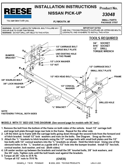
IMPORTANT NOTES USE ONLY TOWING PRODUCTS SUPPLIED OR APPROVED BOLTS,LOCKNUTS, AND WASHERS TO INSTALL THIS HITCHWARNING: DO NOT LUBRICATE THREADS, BOLT FAILURE MAYOCCUR DUE TO OVER TIGHTENING.WARNING: DO NOT DRILL OR WELD TO THIS HITCH .INSTALLATION INSTRUCTIONSProduct No.33048TOOLS REQUIREDYou can take it with you.SMALL PARTSPACKAGE 37557PLYMOUTH, MI(OVER)NISSAN PICK-UP 3/4”SOCKET 9/16”SOCKET 1/2”DRILL TORQUE WRENCH 1/2” CARRIAGE BOLTLARGE BOLT PLATE1/2” LOCK WASHER1/2” NUT USE EXISTING HOLE IN THE FRAMESMALL BOLT PLATEBUMPERBRACKET 3/8” LOCK WASHER3/8” NUT MODELS WITH 75” BED USE THIS DIAGRAM (See second page for models with 56” bed.)1. Remove the bolt from the bottom of the frame on both sides of the vehicle. Insert 1/2” carriage bolt and large bolt plate through large rear hole in the frame. Repeat for the other side.2.Lift the hitch up to frame with the carriage bolts going down through the second hole from the forward end of hitch bracket. Install 1/2" lock washers and nuts on the bolts. See Diagram. Snug up the nuts.3.Attach the “L” brackets to hitch brackets using the 1/2" carriage bolts with small bolt plates and the 1/2”hex bolts with 1/2” conical washers into the "L" brackets as shown. Hold the hitch level. Using one of the obround holes in the “L” bracket as a guide drill a 1/2" hole into the bumper bracket. Install 1/2" hex bolt,conical washer, lock washer, and nut. (Both sides)4. Lift center section up between the brackets and install the 3/8” knurled bolts, 3/8” lock washers, and the 3/8” nuts. Tighten nuts until the bolt heads seat against the brackets.5. Torque all 3/8” nuts to 35 ft.*lb.Torque all 1/2” nuts to 70 ft.*lb.1/2” CARRIAGE BOLT1/2” HEX HEAD BOLT1/2” CONICALWASHER “L” BRACKETFRAME3/8” KNURLED BOLTDRILLED HOLENOTE:FASTENERS TYPICAL, BOTH SIDESTHIS PRODUCT COMPLIES WITH SAFETY SPECIFICATION AND REQUIREMENTS FOR THE STATE OF NEW YORK AND VESC REGULATION V-5 FOR CONNECTION DEVICES AND TOWING SYSTEMS. WEIGHT DISTRIBUTING HITCH RATING IS 5000 LB. MAX. GROSS TRAILER WEIGHT AND 550 LB. MAX.TONGUE WEIGHT. WEIGHT CARRYING HITCH RATING IS 4000 LB. MAX. GROSS TRAILER WEIGHT AND 400 LB. MAX. TONGUE WEIGHT. CONSULT VEHICLE OWNERS MANUAL FOR TOWING RECOMMENDATIONS AND LIMITATIONS.LIMITED WARRANTY USE EXISTING HOLEIN THE FRAME 1/2” CARRIAGE BOLT1/2” LOCK WASHERLARGE BOLT PLATE1/2” NUT3/8” KNURLED BOLT3/8” LOCK WASHER3/8” NUT Towing Products warrants its Hitches, custom Hitch Receivers, and Sway Controls from date of purchase against defects in material andworkmanship under normal use and service, ordinary wear excepted, for the ownership life of the original consumer purchaser. Towing Products will replace FREE OF CHARGE any part which proves defective in material or workmanship when presented to any Towing Products dealer,Towing Products Warehouse, or returned to factory, TRANSPORTATION CHARGES PREPAID, at the address below. THIS WARRANTY IS LIMITED TO DEFECTIVE PARTS REPLACEMENT ONLY. LABOR CHARGES AND/OR DAMAGE INCURRED IN INSTALLATION ORREPLACEMENT AS WELL AS INCIDENTAL AND CONSEQUENTIAL DAMAGES CONNECTED THEREWITH ARE EXCLUDED. Some states do not allow the exclusion or limitation of incidental or consequential damages, so the above limitation or exclusion may not apply to you. Any damage to the Hitch, Custom Hitch receiver or Sway Control as a result of misuse, abuse, neglect, accident, improper installation, or any use violative of instructions furnished by Towing Products , WILL VOID THE WARRANTY.This warranty gives you specific legal rights, and you may also have other rights which vary from state to state. In the event of a problem with warranty service or performance, you may be able to go to a small claims court, a state court, or a federal district court.Towing Products PO Box 810247774 Anchor Ct.Plymouth, MI 48170Towing Products 2351 Winston Park Drive Oakville, Ontario Canada L6H6R7MODELS WITH 56” BED USE THIS DIAGRAM (See page one for models with 75” bed.)1. Remove the bolt from the bottom of the frame on both sides of the vehicle. Insert 1/2” carriage bolt andlarge bolt plate through large rear hole in the frame. Repeat for the other side.2. Lift the hitch up to the frame with the carriage bolts going down through the second hole from rear in thehitch bracket. Install 1/2" lock washers and 1/2" nuts on the bolts. See the diagram above.3. Using the front hole in the bracket as a guide, drill a 1/2" hole in the frame. Insert a 1/2" carriage boltwith a small bolt plate down through the frame and the hitch bracket. Install a 1/2" lock washer and 1/2" nuton the bolt. Repeat for the other side. See the diagram above.4. Lift center section up between the brackets and install the 3/8” knurled bolts, 3/8” lock washers, andthe 3/8” nuts. Tighten nuts until the bolt heads seat against the brackets.5. Torque all 3/8” nuts to 35 ft.*lb.Torque all 1/2” nuts to 70 ft.*lb.NOTE: The above installation can be used for models with 75” beds, but longer ball mounts andweight distributing shanks will be required.1/2” CARRIAGE BOLT SMALL BOLT PLATEFRAMEUSE FORWARD HOLEAS A GUIDE TO DRILL1/2” HOLE IN FRAME.NOTE:FASTENERS TYPICAL, BOTH SIDESUSE SECOND HOLEAS SHOWN.DRILL HOLE IN FRAME FOR THIS BOLT。
电气标准操纵盘系列说明书
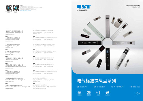
产品以实物为准,效果图仅供参考。
由于本公司持续的产品升级造成的内容变更,恕不另行通知。
版权所有 © 上海贝思特电气有限公司Copyright © Shanghai BST Electric Co.,Ltd.版本号 BST-DQ-HMI- C-22.1.00官方微信官方微信地址:总机: 传真:客服:苏州市吴中区越溪友翔路16号(0512)6637 6666 (0512)6285 67204000-300124苏州默纳克控制技术有限公司Suzhou Monarch Control Technology Co.Ltd地址:总机: 传真:客服:长春汇通光电技术有限公司Changchun Weton Optoelectronic Technology Co., Ltd深圳市宝安区宝城70区留仙二路鸿威工业区E栋(0755)2979 9595 (0755)2961 98974000-300124地址:总机: 传真:客服:深圳市汇川技术股份有限公司Shenzhen Inovance Technology Co.,Ltd地址:总机: 传真:上海市浦东新区航头镇大麦湾工业园航帆路2号(201316)(021)58224368 (021)58223128上海贝思特电气有限公司Shanghai BST Electric Co., Ltd.地址:总机: 传真:浙江省嘉兴市嘉善县姚庄镇福泰路28号(314117)(0573)8477 5858 (0573)8477 5858贝思特电气(嘉兴)有限公司Jiaxing BST Electric Co., Ltd.地址:总机: 传真:浙江省嘉兴市嘉善县姚庄镇福泰路28号(314117)(0573)8477 5858 (0573)8477 5858贝思特机电(嘉兴)有限公司BST Machinery & Electronics (Jiaxing) Co., Ltd地址:总机: 传真:上海市浦东新区航头镇大麦湾工业园航同路2号(201316)(021)58224368 (021)58223128上海贝恩科电缆有限公司Shanghai BNK Cable Co.,Ltd地址:总机: 传真:天津市北辰区津围公路宜兴埠北辰科技园(300400)(022)58102100 (022)58102100*832天津贝思特电气有限公司Tianjing BST Electric Co., Ltd.地址:总机: 传真:广东省佛山市顺德区均安镇沙头智安北路4号(528329)(0757)87663829 (0757)87663211 广东默嘉贝电气有限公司Guangdong MJB Electric Co., Ltd.长春市高新开发区众恒路456号(0431)8105 0600 0105 0611 (0431)8105 0866(0431)8105 0766 8105 07880507091113151718常规系列212519PC/玻璃系列01模块化系列(EN81-20/50)2729全高系列常规系列 | 模块化系列 | PC/玻璃系列 | 全高系列BCGCM008 系列芯子兼容并行、RS485、CAN可替换的铭牌不同楼层可定制相应的按钮板模块化操纵盘EN81-20/50注意:RS485通讯的COP指令板,转接板等需要单独购买小盒子安装。
说明书(乙醇消毒液)

说明书(乙醇消毒液)
乙醇消毒液说明书
【药品名称】
通用名称:乙醇消毒液
商品名称:75%医用酒精(乙醇消毒液)
拼音全码:75%YiYong JiuJing(YiChun XiaoDuYe)
【成分及含量】主要成分为药用乙醇,药用乙醇含量750±50g/L。
【性状】无色透明液体
【产品说明】本品可灭杀肠道致病菌、化脓性球菌和致病性酵母菌等一般细菌繁殖体。
【使用范围】本品适用皮肤表面消毒和一般物体表面消毒。
【包装规格】100ml;220ml;500 ml;1000 ml
【使用方法】
1、皮肤消毒:原液涂擦消毒,作用时间1-3分钟。
2、物体表面消毒:原液擦拭或浸泡消毒物品,作用1.5-3分钟。
【注意事项】
1、本品为外用消毒剂,不得口服,置于儿童不易触及处。
2、本品易燃,远离火源。
3、酒精过敏者慎用。
4、不宜用于脂溶性物体表面的消毒。
【储存条件】避光,置于阴凉、干燥、通风处密封保存。
【有效期】24 月
【卫生许可证号】黔卫计消证字2015第0001号
【执行标准】Q/BZ CP1002-01
【生产企业】贵州省欣紫鸿药用辅料有限公司
【地址】贵州省丹寨县金钟开发区
【邮编】557500
【联系电话】0855-*******。
- 1、下载文档前请自行甄别文档内容的完整性,平台不提供额外的编辑、内容补充、找答案等附加服务。
- 2、"仅部分预览"的文档,不可在线预览部分如存在完整性等问题,可反馈申请退款(可完整预览的文档不适用该条件!)。
- 3、如文档侵犯您的权益,请联系客服反馈,我们会尽快为您处理(人工客服工作时间:9:00-18:30)。
BZ-75-4型
煤矿用气雾阻化泵
使
用
说
明
书
山东中煤工矿物资集团有限公司
煤矿用气雾阻化泵使用说明书
一.概述
BZ-75-4型煤矿用阻化多用泵(以下简称阻化泵)主要用于煤矿井下喷射阻化剂溶液和喷洒阻化汽雾,防止煤炭自燃发火。
在开采有自燃型单一煤层或多分层煤层时,采用阻化剂溶液防火,向采空区残煤喷射阻化剂溶液,抑制残煤自燃,是一种有效方法。
在煤巷中发生高冒并沉积大量浮煤时,可将自制带孔的铁管插入高冒处,与阻化泵的高压胶管连接,将阻化剂溶液喷洒在高冒浮煤上,预防自燃发火。
向采空区喷射阻化剂汽雾,能够取得较好的防火效果,而且经济适用。
阻化汽雾防火,是将雾化喷头设置在采空区漏风点,通过液压泵向可移动的雾化喷头供液,向采空区残煤喷射阻化液雾。
型号说明:
MPa)
L/min)
执行标准:MT/T699—1997
Q/HTY07-2012
GB3836-2010
使用环境:
——环境温度:0℃- +40℃;
——空气相对湿度:≤98%(+25℃);
——大气压力:80kPa-106kPa
——煤矿井下巷道内。
二、结构特征与工作原理:
阻化泵是由防爆电机用三角皮带带动液压泵从动轮以700~800r/min进行工作的,液压泵在曲轴转动一转时,分别在三个唧筒内的三套进水和出水阀组件的作用下进行三次吸水和排水,使具有一定压力的水充满了气室座,由于电机的连续运转,曲轴带动连杆连续推动滑块部件作往复直线运动,从而使阻化泵连续工作。
空气室是用来调节阻化泵流量和压力稳定的,阻化剂溶液是呈翻腾状进入空气室的,使空气室中的空气逐渐溶解在药液中而慢慢减少,一般经过3~4小时的连续运转,空气室内将全部是药液,影响压力的稳定和阻化泵的使用寿命。
压力表为直管标杆式,它的优点是抗震动、耐疲劳、不易损坏。
调压阀是用来调节工作压力的。
调压手柄向顺时针方向扳手是卸压;调压手柄向逆时针方向扳足是加压。
三、技术特征
1、阻化泵是阻化剂防火技术中的关键设备,随机还配备了必要的管路、过滤器及阀门等系统配件。
2、阻化泵即可用喷枪直接向残煤喷射阻化剂,又可利用于雾化喷头喷雾,还可用于向煤体压注阻化剂。
3、阻化泵体积小、重量轻,运输携带方便,尤其对于井下自然条件较差,设备和人员运行不方便,难以运进较大设备的地点最为合适。
4、只需2~3名作业人员,另外配置一辆盛装阻化剂溶液的矿车就可以进行工作。
5、主要技术规格:
型式:煤矿井下轻便型担架式
外形尺寸:(长X宽X高)1500X360X450mm
转速:700~800r/min
额定流量:40L/min
工作压力:1~2.5Mpa
电压:660V/1140V
功率:3.0kw
备件:
管路:内径13mm
喷枪:孔径4mm长度为310mm喷枪一根。
四孔雾化喷头:切向离心式,孔径1.3mm,0.4 m3/h(工作泵压1.5Mpa)。
四、外形尺寸、重量
重量 78kg
五、调试
1、检查及组装:本阻化泵在出厂前已组装完毕并通过各项技术检验合格,但
在运输途中难免震动,故在使用前,除应认真阅读本说明书外,还应卸下防护罩,检查各部件螺丝不得松动,并注意三角带应松紧适宜与二轮平直(可用阻化泵及电机的底脚螺栓调整),再装好防护罩。
2、打开曲轴箱的加油盖,注入GB443-84规定的N15机械油,加到油窗的油位线为止。
3、打开防爆电机的街线盖,接上380V或660V的电源。
4、将带有吸滤网的吸液管与阻化泵的吸液口接上,带有吸滤网的一端置入装满阻化剂溶液的矿车内,将Φ30mm的高压胶管与阻化泵的排液口接上,再连接喷枪或雾化喷头。
5、启动和调压:
(1)启动前,应先将调压手轮向(低)的方向旋松几圈再把调压手柄顺时针方向扳手“卸压“,将吸滤网放入清水中,再送电试喷,要求各接头无渗漏且流量、压力、射程及喷洒状态应达到要求,若启动后不吸水就应该停机查明原因。
(2)启动后,如果电机和阻化泵都运转正常,排液无问题就可以把调压手柄往逆时针方向扳手:加压“再把调压手轮象:高“的方向旋紧至所需压力。
6、压力表所示压力都以由低到高调为准,由高到低调误差较大,可利用调压手柄来回扳动几次,即可指出常压力。
7、阻化泵不可脱水空转,欲停止工作时,必须将调压手柄扳到卸压位置,待阻化泵压力降低后方可停机以免损坏设备。
六、使用、操作步骤
1、开动整机之前,必须将吸水滤网放入水中,将调压阀手柄向顺时针方向搬足。
正确启动动力机。
2、启动后,使之运行10分钟到15分钟期间不要加压。
3、液压泵不能脱水运转,以防止活塞碗损坏。
4、使用中需要加压时,可将调压阀手柄向反时针方向搬动,旋下调压阀手柄,直到压力指示器指示所需的压力。
5、当泵的工作情况正常时,打开截止阀进行喷洒。
6、使用安全警示:1)使用压力最大不可超过3Mpa!
2)连接件松动马上紧固!
七、故障原因分析及排除
八、安全保护及事故处理
1、如果电机不能启动或过热,应立即停机检查,排除故障,防止烧坏电机。
2、进行井下防灭火作业时,应按矿井防灭火规范的要求设立自燃发火观测站点,制定救灾方案及避灾路线,保障操作人员安全。
3、进行井下防灭火作业时,必须根据方案设计要求,防止意外事故。
4、警告:运转时不可用手触摸皮带;不可用手转动皮带轮;不可无皮带外罩运转。
九、保养、维护
1、日常使用:每天工作结束后,须将清水继续喷洒数分钟,祛除阻化泵和管路内的残液。
停机后拆下吸水管,再转动几下皮带轮,以排除阻化泵内的存水,延长设备的使用寿命。
2、定期更换润滑油:当液压泵实际使用200小时左右(不足200小时应每季度)须更换曲轴箱内润滑油一次。
更换时,先旋下油塞和加油盖,将油污放净,然后从加油口处灌入相同牌号机械油,将内部清洗干净;再注入GB443-84规定的N15机械油,切勿用其它油类代替。
如果换油时间未到,发现吸水座下小孔滴液、油位上升、变白或成乳化液体等(说明曲轴箱有药液进入)应立即换油,并更换吸水座内的山形密封圈。
3、长期储存:如长时间不用,应将残液彻底排除干净;卸下三角带、喷枪(雾化喷头)、吸、排液胶管,清洗干净,盘好胶管并将接头对接,阻化泵吸、排液口包好,慎防煤尘等污物进入;擦净阻化泵表面尘污,放置在干燥、通风的库内储存。
4、警告:严禁带电开盖!在维修中严禁损伤防爆面!
十、运输、贮存
1、装备在运输贮存过程中应保持干燥。
2、装备在运输时贮存过程中不可倒置。
3、开箱时应注意检查设置及配件是否完整。
十一、其它
1、订购本产品时应说明产品型号、规格、输送介质等。
2、本单位备有各种配件,用户可来电联系。
请说明主机型号规格,零件名称
及数量,本单位可代办托运。
3、阻化剂的选择:阻化剂种类有多种,一般根据具体煤层的阻化率试验结果
进行选择。
其溶液的浓度、用量及作业时间、地点等应根据煤层条件(自然倾向性、地质构造、煤层水分、工作面丢煤量、采空区漏风状况等参数)确定,以达到最佳技术经济效益。
