MM3575A02VBE_Specifications_Draft.1
GMW14575 试验测试标准
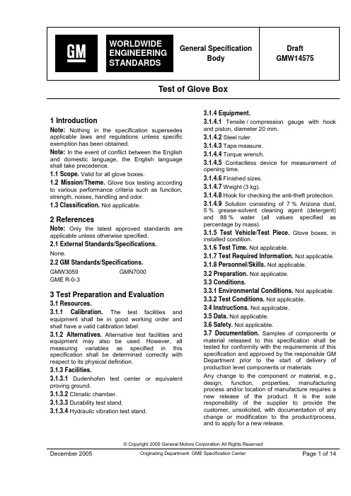
Test of Glove Box© Copyright 2005 General Motors Corporation All Rights ReservedDecember 2005 Originating Department: GME Specification CenterPage 1 of 141 IntroductionNote: Nothing in the specification supersedes applicable laws and regulations unless specific exemption has been obtained.Note: In the event of conflict between the English and domestic language, the English language shall take precedence.1.1 Scope. Valid for all glove boxes.1.2 Mission/Theme. Glove box testing according to various performance criteria such as function, strength, noises, handling and odor. 1.3 Classification. Not applicable.2 ReferencesNote: Only the latest approved standards are applicable unless otherwise specified. 2.1 External Standards/Specifications. None.2.2 GM Standards/Specifications.GMW3059 GMN7000 GME R-0-33 Test Preparation and Evaluation3.1 Resources.3.1.1 Calibration. The test facilities and equipment shall be in good working order and shall have a valid calibration label.3.1.2 Alternatives. Alternative test facilities and equipment may also be used. However, all measuring variables as specified in this specification shall be determined correctly with respect to its physical definition. 3.1.3 Facilities.3.1.3.1 Dudenhofen test center or equivalent proving ground.3.1.3.2 Climatic chamber. 3.1.3.3 Durability test stand.3.1.3.4 Hydraulic vibration test stand.3.1.4 Equipment.3.1.4.1 Tensile / compression gauge with hook and piston, diameter 20 mm. 3.1.4.2 Steel ruler. 3.1.4.3 Tape measure. 3.1.4.4 Torque wrench.3.1.4.5 Contactless device for measurement of opening time.3.1.4.6 Finished sizes. 3.1.4.7 Weight (3 kg).3.1.4.8 Hook for checking the anti-theft protection. 3.1.4.9 Solution consisting of 7 % Arizona dust, 5 % grease-solvent cleaning agent (detergent) and 88 % water (all values specified as percentage by mass).3.1.5 Test Vehicle/Test Piece. Glove boxes, in installed condition.3.1.6 Test Time. Not applicable.3.1.7 Test Required Information. Not applicable. 3.1.8 Personnel/Skills. Not applicable. 3.2 Preparation. Not applicable. 3.3 Conditions.3.3.1 Environmental Conditions. Not applicable. 3.3.2 Test Conditions. Not applicable. 3.4 Instructions. Not applicable. 3.5 Data. Not applicable. 3.6 Safety. Not applicable.3.7 Documentation. Samples of components or material released to this specification shall be tested for conformity with the requirements of this specification and approved by the responsible GM Department prior to the start of delivery of production level components or materials.Any change to the component or material, e.g., design, function, properties, manufacturing process and/or location of manufacture requires a new release of the product. It is the sole responsibility of the supplier to provide the customer, unsolicited, with documentation of any change or modification to the product/process, and to apply for a new release.If not otherwise agreed to the entire verification test shall be repeated and documented by the supplier prior to start of delivery of the modified or changed product. In some cases a shorter test can be agreed to between the responsible GM Department and the supplier.3.7.1 Test Results. Variables are provided for values which are not explicitly listed. The values are given in appendix G. Deviations of these values will be defined in the according drawing. Subjective evaluation shall be performed according to GMN7000.The results shall be entered in the relevant data sheets (Appendices B to E).3.7.2 Deviations from Test Procedure. Deviations from the requirements of the test procedures shall have been agreed upon. Such requirements shall be specified on component drawings, test certificates, reports, etc.3.4.2.1 The durability test shall be performed at temperatures of: • (-30 ± 2) °C • (+20 ± 2) °C •(+80 ± 2) °C3.4.2.2 All performance requirements shall be fulfilled within a temperature range of (-30...+80) °C. 3.4.2.3 The following 3 temperature ranges shall be selected for the test: 4 Requirements and Procedure4.1 General. The glove box shall be checked forconformance to the current development, drawing or release status before commencement of each test.All fasteners shall be present, undamaged and correctly installed. If this is not the case, the fasteners shall be supplemented or corrected. Any modifications shall be noted.4.2 Measurement of Release Force F1. The tensile / compression gauge with hook shall be used for measuring the release force F1.The hook shall be applied directly to the opening handle of the glove box and shall release the locking mechanism, causing the glove box lid to open.Measurement shall be performed horizontally. The release force F1 shall be measured individually for the left, right and center of the release handle in the vehicle longitudinal direction.Three measurement values shall be recorded for each measurement.Required release force F1 as specified by appendix G. Deviations of these values will be defined in according drawing.4.3 Measurement of Closing Force F2 / Locking Force F3. The tensile / compression gauge with piston (diameter 20 mm) shall be used to measure the closing/locking force.Measurement of the locking force shall be© Copyright 2005 General Motors Corporation All Rights ReservedDecember 2005 Page 3 of 14Closing force F2 designates the maximum force required to contact with the locking mechanism from the opened position. Locking force F3 is the maximum force required to complete locking from the point of contact with the locking mechanism. Three measurement values shall be recorded for each measurement.For the required closing force F2 or locking force F3 and point of application S1 see appendix G. Deviations of these values will be defined in according drawing.4.4 Measurement of the Key Torque MD1. For lockable glove boxes, the key torque shall be measured with the torque wrench.The torque wrench shall be applied directly to the key and shall turn it to the opening and closing directions.See relevant drawing for the required key torque MD1.4.5 Measurement of Opening Time T1 (Version with Lid Brake). The measurement of the opening time takes place by means of an automatic stop watch, which measures the time contactless e.g. over a light barrier starting from the time of release up to the completely opened position. A time study by hand is too inaccurate and therefore not permitted.To perform the measurement, it is advisable to deactivate the locking mechanism, hold the lid in the closed position and start measuring automatically as soon as the lid starts to move. The specifications for the opening time are temperature-dependent. The value is defined by the average travelling speed V to consider the possible different designs of the systems. The allowed speed V is listed in the appendix.Definition how calculate the allowed opening time from speed requirements:1 Measure the max. opening angle α. Measurethe distance R from hinge to the point that actuates the contactless stopwatch or light barrier.2 The traverse path S and the allowed openingtime t is calculated as follows:VR V S t R S ⋅⋅⋅⋅==⇒⋅⋅⋅=36023602απαπ 4.6 Load Test at driving conditions. Before the test, the actuating forces shall be measured according to paragraph 4.2 to 4.5. Noises occurring when stationary and during driving operation shall be evaluated according to GMN7000.Subject to the volume of the glove box the following weights should be used: •V < 6l with 2 kg• V ≥ 6l with 3 kgThe dimensions of the weight shall be (210 x 150) mm; the height shall vary according to the material used.The program P3 shall then be driven on the test track according to GME R-0-3 (2000 km, Belgian block wave road).There shall be no damage or impairment of function in the glove box after the test.The operating forces shall conform to the specifications before and after the test. In addition, there shall be no deterioration in noise behavior when stationary and during driving operation.4.7 Load Test glove box shelf: For the measurement of the deflection and firmness of the glove box shelf a glove compartment is fastened as component part without tension on a device. The tensile / compression gauge with piston (diameter 20 mm) shall be used. The load shall be induced in the middle of the glove box shelf, 20mm from the rear edge (referring to driving direction).The deformation on that point is measured with the help of a dial gauge, which is positioned on the lower side of the shelf (see figure 2). The values are to be documented.GMW14575 GM WORLDWIDE ENGINEERING STANDARDS© Copyright 2005 General Motors Corporation All Rights ReservedPage 4 of 14 December 2005Figure 2: Measurement of deflection and firmness of the glove box shelfThe specified forces and values for deformation are listed in appendix G. Deviations of these values are given in according drawing.Any deviations which are established in the glove box shall be examined and recorded.4.8 Closing and Opening Behavior Test. The closing and opening behavior of the glove box shall be tested from the driver's and passenger's seats when stationary and during driving operation. The following points shall be evaluated: • Perfect closing of the box at any point of application.• Opening of the box when stationary and during driving operation.• Noises when releasing, opening or closing. • Noises from the opening stop of the lid.•Swinging back of the lid on reaching the opening stop.Perfect opening and closing of the glove box shall be possible from the driver's and passenger's seats when stationary and during driving operation. The glove box lid shall open automatically after being released.Rating ≥ 7 shall be attained for the following characteristics according to GMN7000: • Closing and opening behavior•Closing and opening noise (functional noise)• Noise from the opening stopSignificant swinging back of the lid is not permissible.4.9 Illumination Test.4.9.1 The glove box interior shall be checked for sufficient illumination.Rating ≥ 7 shall be attained according to GMN7000.4.9.2 For vehicles with illumination switch the illumination shall be switched off when the lid is closed.4.9.3 A check shall be made for evidence of light diffusion through surrounding parts when the glove box illumination is switched on.4.9.4 For vehicles with permanent illumination (without switch), there shall be no light diffusion through surrounding parts or through the glove box lid joint when the glove box illumination is switched on.4.9.5 The tests in paragraph 4.9.3 and 4.9.4 shall be performed in the dark if possible.© Copyright 2005 General Motors Corporation All Rights ReservedDecember 2005 Page 5 of 144.10 View Protection Test. The contents of the closed glove box shall not be visible from outside. 4.11 Anti-theft Protection Test. The anti-theft protection shall be tested with the glove box locked using the hook and tensile / compression gauge.The hook shall be attached to both the upper edge and center of the glove box lid (see Figure 3) and then be pulled in the lid opening direction with the tensile / compression balance.See relevant drawing for the required break-open force F4.Displacement of the lock as a result of pushing therelease handle using the tensile / compression gauge with hook (see Figure 4) when the glove box is locked.The minimum pull-out force F5 is specified in the relevant drawing. The release handle shall not break away or become unclipped from the lid up to this value.In addition, the lid shall not open.Any damage shall be examined and recorded.4.12.2 Vehicles without Lockable Glove Boxes. The force shall be applied horizontally at the release handle using the tensile / compression gauge with hook (see Figure 4). The lid shall be held shut to prevent it from opening.The minimum pull-out force F5 is specified in the relevant drawing. The release handle shall not break away or become unclipped from the lid up to this value.Any damage shall be examined and recorded.Figure 4: Testing the pull-out force of the release handle F5values are given in according drawing.The minimum pull-out force F6 is specified in the appendix G. Deviations of these values are given in according drawing.Any damage to the glove box shall be examined and recorded.GMW14575 GM WORLDWIDE ENGINEERING STANDARDS© Copyright 2005 General Motors Corporation All Rights ReservedPage 6 of 14 December 2005Figure 5: Open Glove Box Deflection4.14 Durability Test. The durability test consists of a fatigue test (paragraph 4.14.1) and a vibration test (paragraph 4.14.2).The same test piece shall be used for the fatigue test and the vibration test. The sequence may be changed.The opening time (only Boxes with a damped lid) and opening and closing forces shall be measured and the noises occurring on opening and closing shall be evaluated according to GMN7000 before the test, between the fatigue test and the vibration test and at the end of the durability test.Furthermore, the test piece shall be installed in a new vehicle and evaluated for noise before and after the complete test.The results shall be noted accordingly.4.14.1 Fatigue Test. The removed glove box shall be installed in a rigid aluminum profile frame at the original bolting points and in the installation position on the durability test stand.The reliability shall be 97.8 % or greater at 50 % confidence for one severe customer usage with an assumed Weibull slope of 1.5.That means: Test 6 parts to failure up to a maximum of 3 times life to the following cycling temperature profile.Measure efforts before cycling and after each life. Normalize part to (+23 ± 5) °C after hot and cold cycles to avoid inducing thermal shock.4.14.1.1 Glove Box Operational Cycles.One life equals 10 000 cycles consisting of unlatching, opening, closing, and latching the door. • Run 7000 cycles at (+23 ± 5) °C • Run 1000 cycles at (+85 ± 5) °C • Run 1000 cycles at (-30 ± 5) °C•Run 1000 cycles at (+40 ± 5) °C and 95 % Relative Humidity (RH)Cycle at a maximum of 10 cycles per minute. For damped devices, adjust cold temperature cycle from (-30…-20) °C and if necessary decrease cycles per minute. 4.14.1.2 Storage Compartment Lock Operational Cycle.One life equals 1000 cycles of inserting key, locking, pulling out key, inserting key, unlocking, and pulling out key. • Run 700 cycles at (+23 ± 5) °C • Run 100 cycles at (+85 ± 5) °C •Run 100 cycles at (-30 ± 5) °C• Run 100 cycles at (+40 ± 5) °C and 95 % RH Cycle at a maximum of 5 cycles per minute.© Copyright 2005 General Motors Corporation All Rights ReservedDecember 2005 Page 7 of 144.14.2 Vibration Test. The demounted glove box shall be installed in a rigid aluminum profile frame at the original bolting points and in the installation position on the hydraulic oscillation test stand.For glove boxes in which the lid simultaneously forms part of the box (Hopper type), test steps 1 to 3 (see paragraph 4.14.2.1 to paragraph 4.14.2.3) shall be performed twice, halving the test period each time.The first run shall be performed without additional loading of the lid or box. A weight of 3 kg shall be attached to the center of the lid or box for the second run (see paragraph 4.5 for dimensions). 4.14.2.1 Test Step 1.Vibration stress begins with a frequency of (5....15) Hz (frequency cycle run in 100 s) and a maximum acceleration of ± 1 g at (+23 ± 5) °C. The test period is 40 h at (+23 ± 5) °C. 4.14.2.2 Test Step 2.In the second step of the test, the maximum acceleration shall be increased to ± 1.5 g at a frequency of (5....15) Hz.The test period is 30 h at (+23 ± 5) °C. 4.14.2.3 Test Step 3.In the third step of the test, the ambient temperature shall be set to +80 °C for 1 h with a frequency of (5....15) Hz and a maximum acceleration of ± 1.5 g.4.14.3 Requirements. There shall be no damage to the glove box after the durability test. Any damage shall be examined and recorded.The actuation forces (see paragraph 4.2 to 4.4) and opening times (see paragraph 4.5), if necessary, shall conform to the specifications of the individual tests (see relevant drawing) after testing is completed. Deviations from the initial measurements shall be recorded.After testing, the opening and closing behavior (see paragraph 4.8) shall attain Rating 7 according to GMN7000. Deviations from the initial measurements shall be recorded.Noises from the glove box during driving operation shall not be permitted after the durability test. Deviations from the initial measurements shall be recorded.5 Provisions for Shipping6 Notes6.1 Glossary. Not applicable.6.2 Acronyms, Abbreviations, and Symbols. Not applicable.7 Additional Paragraphs7.1 All parts or systems supplied to this specification must comply with the requirements of GMW3059, Restricted and Reportable Substances for Parts.7.2 This document is based on GME 01113.8 Coding SystemThis specification shall be referenced in other documents, drawings, VTS, CTS, etc. as follows: GMW145759 Release and Revisions9.1 Release. This standard originated in (replace with date [month/year] standard number was issued). It was first approved by (replace with approving organization’s name) in (replace with original approval date [month/year]). It was first published in (replace with original publication date [month/year]). 9.2 Revisions.Appendix AList of Measuring DevicesDate of measurement:© Copyright 2005 General Motors Corporation All Rights ReservedPage 8 of 14 December 2005Appendix BData Sheet 1Project: Test temperature:Vehicle no.: Date:Design status: Tester:Test location:© Copyright 2005 General Motors Corporation All Rights ReservedDecember 2005 Page 9 of 14Appendix CData Sheet 2Project: Test temperature:Vehicle no.: Date:Design status: Tester:Test location:© Copyright 2005 General Motors Corporation All Rights ReservedPage 10 of 14 December 2005Appendix DData Sheet 3Project: Test temperature:Vehicle no.: Date:Design status: Tester:Test location:© Copyright 2005 General Motors Corporation All Rights ReservedAppendix EData Sheet 4Project: Test temperature:Vehicle no.: Date:Design status: Tester:Test location:© Copyright 2005 General Motors Corporation All Rights ReservedAppendix FData Sheet 5Project: Test temperature:Vehicle no.: Date:Design status: Tester:Test location:© Copyright 2005 General Motors Corporation All Rights ReservedAppendix GRequirement SheetNote1: Above operating efforts apply through all temperature ranges and to parts that have and have not been cycled. Note 2: Requires Finite Element Analysis (FEA) applies to all misuse forces. Test 2 parts until breaks and note failure mode. Note 3: Only check opening time when damped.© Copyright 2005 General Motors Corporation All Rights Reserved。
Hewlett-Packard Model 355C, 355D, 355E, and 355F V
\-'"
Model355C/D/E/F
Page 3
Do not exceed the RF power rating of
0.5W auerage, or 2450W peak with a
maximum pulse width of 200 ps. Do not connect an attenuator RF input or output connector to greater than !5 Vdc.
(J luFttl!
r6Clf 6- o- o-
OPERATING
\-
AND SERVICE MANUAL
355C 355D 355E 355F
VHF ATTENUATOR
U
Printed: AU G UST 1980
\-
@@
rcE H"=&TJJ
If the attenuator must be connected to a
deuice with a potential gxeater than x5 Vdc, use a blocking capacitor.
Accessories Supplied
The 355E and 355F programmable attenuators are
trically. A procedure for checking electrical per-
formance is given under "Operator's Check" (see
PERFORMANCE TESTS). If the contents of the shipment are incomplete, if there is mechanical damage or defect, or if the instrument does not pass the electrical performance test, notify the nearest Hewlett-Packard office. If the shipping con-
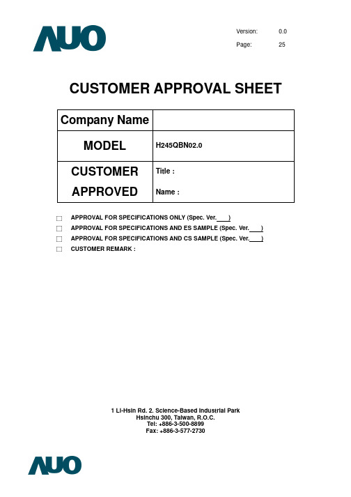
H245QBN02__+Specification_20120824
--
262k Colors
8
NTSC Ratio
%
50
9
Display Mode
--
ECB Normally white
10
Weight
g
2.4g
11Inteຫໍສະໝຸດ face1-Lane MIPI I/F
12
Viewing angle
CR>10:1 at 50 degree
Note 1: Not include FPCs extrude stucture.
1V8
-0.3 ~ +5.0
V
VIN
-0.3 ~ (1.8+0.5)
V
1
LED Current
ILED
25
mA
2
Operating Temperature
TOP
-20 ~ +70
°C
3
Storage Temperature
TSTG
-30 ~ +80
°C
3
Humidity
H
5% ~ 95%
RH
3
(1)Applies to DISP_D0_N, DISP_D0_P, DISP_CLK_N, DISP_CLK_P, DISP_SYNC, DISP_RESET_L (2) Applies for each LED individually (3) See Section 7 for specific temperature and humidity test conditions.
© 2012 AU Optronics All Rights Reserved, Do Not Copy.
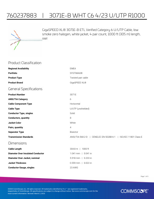
GigaSPEED XL 3071E-B ETL Verified Category 6 U UTP
GigaSPEED XL® 3071E-B ETL Verified Category 6 U/UTP Cable, lowsmoke zero halogen, white jacket, 4 pair count, 1000 ft (305 m) length,reelProduct ClassificationRegional Availability EMEAPortfolio SYSTIMAX®Product Type Twisted pair cableProduct Brand GigaSPEED XL®General SpecificationsProduct Number3071EANSI/TIA Category6Cable Component Type HorizontalCable Type U/UTP (unshielded)Conductor Type, singles SolidConductors, quantity8Jacket Color WhitePairs, quantity4Separator Type BisectorTransmission Standards ANSI/TIA-568.2-D | CENELEC EN 50288-6-1 | ISO/IEC 11801 Class E DimensionsCable Length304.8 m | 1000 ftDiameter Over Insulated Conductor 1.041 mm | 0.041 inDiameter Over Jacket, nominal 5.918 mm | 0.233 inJacket Thickness0.559 mm | 0.022 inConductor Gauge, singles23 AWG13Page ofCross Section DrawingElectrical Specificationsdc Resistance Unbalance, maximum 5 %dc Resistance, maximum7.61 ohms/100 m | 2.32 ohms/100 ftDielectric Strength, minimum2500 VdcMutual Capacitance at Frequency 5.6 nF/100 m @ 1 kHzNominal Velocity of Propagation (NVP)70 %Operating Frequency, maximum300 MHzOperating Voltage, maximum80 VRemote Powering Fully complies with the recommendations set forth by IEEE 802.3bt (Type4) for the safe delivery of power over LAN cable when installed accordingto ISO/IEC 14763-2, CENELEC EN 50174-1, CENELEC EN 50174-2 or TIATSB-184-ASegregation Class cMaterial SpecificationsConductor Material Bare copperInsulation Material PolyolefinJacket Material Low Smoke Zero Halogen (LSZH)Separator Material PolyolefinPage of23Mechanical SpecificationsPulling Tension, maximum11.34 kg | 25 lbEnvironmental SpecificationsInstallation temperature0 °C to +60 °C (+32 °F to +140 °F)Operating Temperature-20 °C to +60 °C (-4 °F to +140 °F)Acid Gas Test Method EN 50267-2-3EN50575 CPR Cable EuroClass Fire Performance B2caEN50575 CPR Cable EuroClass Smoke Rating s1aEN50575 CPR Cable EuroClass Droplets Rating d0EN50575 CPR Cable EuroClass Acidity Rating a1Environmental Space Low Smoke Zero Halogen (LSZH)Smoke Test Method IEC 61034-2Packaging and WeightsCable weight38.097 kg/km | 25.6 lb/kftPackaging Type ReelRegulatory Compliance/CertificationsAgency ClassificationCENELEC EN 50575 compliant, Declaration of Performance (DoP) availableCHINA-ROHS Below maximum concentration valueISO 9001:2015Designed, manufactured and/or distributed under this quality management system REACH-SVHC Compliant as per SVHC revision on /ProductCompliance ROHSCompliantPage of33。
ProductTypeList-optiMOS(20-250V)

N-Channel MOSFETs: OptiMOS™ (20V…250V) Product TypeProduct TypeBSN045NE2LSBSN011NE2LSBSN011NE2LSIBSN012N03LSBSN012N03LSIBSN048N03LSBSB012NE2LXBSB014N04LX3 GBSB015N04NX3 GBSB017N03LX3 GBSB012N03LX3 GBSB028N06NN3 GBSB044N08NN3 GBSB056N10NN3 GBSB013NE2LXIBSB008NE2LXBSB280N15NZ3 G BSB165N15NZ3 G BSB012NE2LXI BSF024N03LT3 G BSF050N03LQ3 G BSF030NE2LQ BSF134N10NJ3 G BSF110N06NT3 G BSF450NE7NH3 G BSF035NE2LQ IPB015N04L G IPB027N10N3 G IPB035N08N3 G IPB015N04N G IPB019N06L3 G IPB083N10N3 G IPB042N10N3 G IPB054N06N3 GIPB037N06N3 G IPB097N08N3 G IPB055N03L G IPB054N08N3 G IPB042N03L G IPB022N04L G IPB065N03L G IPB072N15N3 G IPB025N08N3 G IPB080N03L G IPB081N06L3 G IPB147N03L G IPB096N03L G IPB136N08N3 GIPB090N06N3 G IPB029N06N3 G IPB049NE7N3 G IPB031NE7N3 G IPB020NE7N3 G IPB123N10N3 G IPB038N12N3 G IPB144N12N3 G IPB320N20N3 G IPB107N20N3 G IPB200N25N3 G IPB600N25N3 G BUZ32 H3045A BUZ31 H3045A IPB108N15N3 G BUZ30A H3045AIPB107N20NA IPB057N06N IPB026N06N IPB230N06L3 G IPB067N08N3 G IPB034N03L G IPB009N03L G IPB011N04L G IPB011N04N G IPB016N06L3 G IPB017N06N3 G IPB019N08N3 G IPB020N04N G IPB025N10N3 G IPB030N08N3 GIPB036N12N3 G IPB065N15N3 G IPB010N06NIPB014N06NSPD07N20 GIPD031N06L3 G IPD034N06N3 G IPD035N06L3 G IPD036N04L GIPD038N06N3 G IPD048N06L3 G IPD053N08N3 G SPD50N03S2L-06 G SPD30N03S2L-07 G IPD068N10N3 G SPD50N03S2-07 GIPD082N10N3 G IPD088N06N3 G IPD096N08N3 G SPD30N03S2L-10 G IPD127N06L GIPD135N08N3 G IPD160N04L GIPD170N04N GIPD200N15N3 G SPD30N03S2L-20 G IPD220N06L3 G IPD25CN10N GIPD250N06N3 G IPD33CN10N GIPD350N06L GIPD640N06L G IPD78CN10N G IPD800N06N G IPD122N10N3 G IPD180N10N3 G IPD110N12N3 G IPD031N03L G IPD040N03L G IPD050N03L G IPD060N03L G IPD075N03L G IPD090N03L G IPD320N20N3 G IPD600N25N3 G IPD530N15N3 G IPD105N03L G IPD135N03L GIPD025N06N IPD053N06N IPI023NE7N3 G IPI034NE7N3 G IPI052NE7N3 G IPI126N10N3 G IPI180N10N3 G IPI041N12N3 G IPI076N12N3 G IPI147N12N3 G IPI045N10N3 G IPI086N10N3 G IPI030N10N3 G IPI04CN10N G IPI072N10N3 G IPI26CN10N G IPI35CN10N GIPI075N15N3 G IPI200N15N3 G IPI024N06N3 G IPI032N06N3 G IPI040N06N3 G IPI037N08N3 G IPI320N20N3 G IPI110N20N3 G IPI200N25N3 G IPI600N25N3 G IPI111N15N3 G IPI530N15N3 G IPI020N06NIPI029N06N BUZ31 H3046 IPI084N06L3 GIPU135N08N3 G IPS110N12N3 G IPS060N03L G IPS075N03L G IPS031N03L G IPS040N03L G IPS090N03L G IPS105N03L G IPS135N03L G IPS050N03L G BSZ0908ND BSZ0907ND BSC0921NDI BSC0923NDI BSC0924NDI BSC0925ND BSC0910NDI BSC0911NDBSZ035N03LS G BSZ035N03MS G BSZ040N04LS G BSZ042N04NS G BSZ050N03LS G BSZ050N03MS G BSZ058N03LS G BSZ058N03MS G BSZ067N06LS3 G BSZ076N06NS3 G BSZ088N03MS G BSZ088N03LS G BSZ097N04LS G BSZ100N06LS3 G BSZ100N03MS GBSZ105N04NS G BSZ110N06NS3 G BSZ123N08NS3 G BSZ130N03MS G BSZ130N03LS G BSZ165N04NS G BSZ340N08NS3 G BSZ440N10NS3 G BSZ160N10NS3 G BSZ900N15NS3 G BSZ520N15NS3 G BSZ0909NSBSZ240N12NS3 G BSZ12DN20NS3 G BSZ16DN25NS3 GBSZ42DN25NS3 G BSZ900N20NS3 G BSZ060NE2LS BSZ065N03LS BSZ036NE2LS BSZ018NE2LS BSZ0901NSBSZ0901NSIBSZ0902NSBSZ0904NSIBSZ0902NSIBSZ018NE2LSI BSZ042N06NS BSZ023N04LS BSZ150N10LS3 G BSO615N GBSO033N03MS GBSO083N03MS G BSO110N03MS G BSO330N02K G BSO150N03MD G BSO220N03MD G BSC010NE2LS BSC050NE2LS BSC046N02KS G BSC019N02KS G BSC014N03LS G BSC016N03LS G BSC014N03MS G BSC016N04LS G BSC016N03MS G BSC017N04NS G BSC018N04LS GBSC020N03MS G BSC020N03LS G BSC025N03MS G BSC027N04LS G BSC025N03LS G BSC028N06LS3 G BSC030N03MS G BSC030N04NS G BSC030N03LS G BSC031N06NS3 G BSC034N03LS G BSC035N04LS G BSC042N03MS G BSC042N03LS GBSC050N03MS G BSC050N04LS G BSC050N03LS G BSC054N04NS G BSC057N03MS G BSC057N03LS G BSC057N08NS3 G BSC059N04LS G BSC060N10NS3 G BSC067N06LS3 G BSC076N06NS3 G BSC079N10NS GBSC080N03LS G BSC082N10LS G BSC090N03MS G BSC090N03LS G BSC093N04LS G BSC100N03MS G BSC100N10NSF G BSC100N06LS3 G BSC105N10LSF G BSC110N06NS3 G BSC118N10NS G BSC120N03MS G BSC120N03LS GBSC123N10LS G BSC152N10NSF G BSC190N15NS3 G BSC159N10LSF G BSC196N10NS G BSC205N10LS G BSC252N10NSF G BSC265N10LSF G BSC340N08NS3 G BSC042NE7NS3 G BSC160N10NS3 G BSC440N10NS3 G BSC077N12NS3 G BSC190N12NS3 G BSC520N15NS3 GBSC600N25NS3 G BSC026N02KS G BSC070N10NS3 G BSC109N10NS3 G BSC0909NSBSC360N15NS3 G BSC0908NSBSC240N12NS3 G BSC900N20NS3 G BSC12DN20NS3 G BSC16DN25NS3 G BSC22DN20NS3 G BSC018NE2LS BSC024NE2LS BSC011N03LS BSC052N03LSBSC0902NSBSC032NE2LS BSC0901NSIBSC0904NSIBSC010NE2LSI BSC0902NSIBSC014NE2LSI BSC018NE2LSI BSC011N03LSI BSC0906NSBSC009NE2LS BSC036NE7NS3 G BSC046N10NS3 G BSC028N06NS BSC010N04LSI BSC014N04LS BSC014N04LSIBSC039N06NS BSC014N06NS BSC010N04LS BSC500N20NS3 G BSC022N04LS BSC072N03LD G BSC150N03LD G BSC750N10ND G IPP023NE7N3 G IPP034NE7N3 G IPP052NE7N3 G BUZ31L HBUZ73 HBUZ73A HBUZ73AL HBUZ73L HIPP180N10N3 G IPP041N12N3 G IPP048N12N3 G IPP076N12N3 G IPP114N12N3 G IPP147N12N3 G IPP030N10N3 G IPP045N10N3 G IPP04CN10N G IPP05CN10N G IPP072N10N3 G IPP086N10N3 G IPP12CN10L G IPP16CN10N G IPP075N15N3 G IPP200N15N3 G IPP034N03L GIPP055N03L G IPP065N03L G IPP080N03L G IPP096N03L G IPP114N03L G IPP015N04N G IPP023N04N G IPP039N04L G IPP041N04N G IPP024N06N3 G IPP032N06N3 G IPP037N06L3 G IPP040N06N3 G IPP052N06L3 G IPP057N06N3 G IPP084N06L3 G IPP093N06N3 GIPP028N08N3 G IPP037N08N3 G IPP057N08N3 G IPP070N08N3 G IPP100N08N3 G IPP139N08N3 G IPP320N20N3 G IPP110N20N3 G IPP200N25N3 G IPP600N25N3 G BUZ31 HBUZ32 HIPP111N15N3 G BUZ30A HIPP065N04N G IPP530N15N3 GIPP048N04N G IPP110N20NA IPP147N03L G IPP029N06N IPP020N06N IPP040N06N IPP060N06N IPA028N08N3 G IPA037N08N3 G IPA057N08N3 G IPA100N08N3 G IPA045N10N3 G IPA086N10N3 G IPA126N10N3 G IPA180N10N3 G IPA030N10N3 GIPA105N15N3 G IPA032N06N3 G IPA057N06N3 G IPA093N06N3 G IPT004N03L IPT007N06N IPT020N10N3 IPT059N15N3Datasheet Group Product Status /dgdl/BSN045NE2LS_rev1.0.pdf?fBlade 3x3 (USON-6)in production olderId=db3a304313b8b5a60113cee8763b02d7&fileId=db3a30433d68e984013d7ca959855780/dgdl/BSN011NE2LS_rev1.3.pdf?fBlade 3x3 (USON-6)in production olderId=db3a304313b8b5a60113cee8763b02d7&fileId=db3a30433d68e984013d7cbfeef05815Blade 3x3 (USON-6)in production /dgdl/BSN011NE2LSI_rev1.3.pdf?folderId=db3a304313b8b5a60113cee8763b02d7&fileId=db3a30433d68e984013d7ccf22ee58e4Blade 3x3 (USON-6)in production /dgdl/BSN012N03LS_rev1.3.pdf?folderId=db3a304313b8b5a60113cee8763b02d7&fileId=db3a30433d68e984013d7cde510c594c/dgdl/BSN012N03LSI_rev1.3.pdf?Blade 3x3 (USON-6)in production folderId=db3a304313b8b5a60113cee8763b02d7&fileId=db3a30433d68e984013d7cea5f8559f4Blade 3x3 (USON-6)in production /dgdl/BSN048N03LS_rev1.0.pdf?folderId=db3a304313b8b5a60113cee8763b02d7&fileId=db3a30433d68e984013d7cf6d2e25a60/dgdl/BSB012NE2LX_Rev+2.3.pdfCanPAK™ M-size in production?folderId=db3a304326dfb1300126fb3bec803f1a&fileId=db3a304326dfb1300126fb6a32613f3dCanPAK™ M-size in production /dgdl/BSB014N04LX3+G_Rev+2.3.pdf?folderId=db3a304313b8b5a60113cee8763b02d7&fileId=db3a304320d39d590121a02c6c737a9bCanPAK™ M-size in production /dgdl/BSB015N04NX3+G_Rev+2.4.pdf?folderId=db3a304313b8b5a60113cee8763b02d7&fileId=db3a304320d39d590121a03bbfcd7aacCanPAK™ M-size in production /dgdl/BSB017N03LX3+G_Rev+2.2.pdf?folderId=db3a304313b8b5a60113cee8763b02d7&fileId=db3a304320d39d590121a04b132c7abb/dgdl/BSB012N03LX3+G_Rev_+2CanPAK™ M-size in production.1_pdf.pdf?folderId=db3a304313b8b5a60113cee8763b02d7&fileId=db3a304320d39d590121a0112ce07a8b/dgdl/BSB028N06NN3_G_rev2.0.CanPAK™ M-size in production pdf?folderId=db3a30431441fb5d01148ca9f1be0e77&fileId=db3a30432e25b009012e29fda4e23838/dgdl/BSB044N08NN3_G_rev2.0.CanPAK™ M-size in production pdf?folderId=db3a304313b8b5a60113cee8763b02d7&fileId=db3a30435819ae2e012e385cde7b70d4CanPAK™ M-size in production /dgdl/BSB056N10NN3+G_Rev+2.5.pdf?folderId=db3a304313b8b5a60113cee8763b02d7&fileId=db3a30442e152e91012e390b9a631459/dgdl/BSB013NE2LXI_Rev+2.3.pdCanPAK™ M-size in production f?folderId=db3a304313b8b5a60113cee8763b02d7&fileId=db3a30432e398416012e47a158802577/dgdl/BSB008NE2LX_Rev+1.3.pdfCanPAK™ M-size in production?folderId=db3a304313b8b5a60113cee8763b02d7&fileId=db3a30432e564707012e5745ca7d000eCanPAK™ M-size in production /dgdl/BSB280N15NZ3+G+Rev+2.5_.pdf?folderId=db3a304326623792012669f6bee2224b&fileId=db3a30432e779412012e7b0b544c3852CanPAK™ M-size in production /dgdl/BSB165N15NZ3+G+Rev+2.2.pdf?folderId=db3a304326623792012669f6bee2224b&fileId=db3a30432e779412012e7b04a1353843/dgdl/BSB012NE2LXI_rev1+1.pdfCanPAK™ M-size coming soon?folderId=db3a304313b8b5a60113cee8763b02d7&fileId=db3a30433f764301013f805e3eb247c1CanPAK™ S-size in production /dgdl/BSF024N03LT3+G_Rev+2.1_pdf.pdf?folderId=db3a30431ddc9372011ebafa04517f8b&fileId=db3a30432239cccd012282adaadf7bc8CanPAK™ S-size in production /dgdl/BSF050N03LQ3+G_Rev+2.2.pdf?folderId=db3a304313b8b5a60113cee8763b02d7&fileId=db3a304320d39d590121a0f584407b1cCanPAK™ S-size in production /dgdl/BSF030NE2LQ_Rev+2.3.pdf?folderId=db3a304313b8b5a60113cee8763b02d7&fileId=db3a30432e398416012e47a8f0792588/dgdl/BSF134N10NJ3+G_Rev+2.5CanPAK™ S-size in production.pdf?folderId=db3a304313b8b5a60113cee8763b02d7&fileId=db3a30432e779412012e7afa4a6c3834CanPAK™ S-size in production /dgdl/BSF110N06NT3_G_rev2.0.pdf?folderId=db3a304313b8b5a60113cee8763b02d7&fileId=db3a3043382e837301387b92fdc80c37CanPAK™ S-size in production /dgdl/BSF450NE7NH3G_rev2.0.pdf?folderId=db3a304313b8b5a60113cee8763b02d7&fileId=db3a30433a047ba0013a687e2ae403daCanPAK™ S-size coming soon /dgdl/BSF035NE2LQ_rev1+1.pdf?folderId=db3a304313b8b5a60113cee8763b02d7&fileId=db3a30433f764301013f7fe8a925463cD2PAK (TO-263)in production /dgdl/IPB015N04L_rev1.2.pdf?folderId=db3a304313b8b5a60113cee8763b02d7&fileId=db3a30431936bc4b0119382488c359d3D2PAK (TO-263)in production /dgdl/IPB027N10N3+G_Rev2.4.pdf?folderId=db3a304313b8b5a60113cee8763b02d7&fileId=db3a30431ce5fb52011d1ed9348e15efD2PAK (TO-263)in production /dgdl/IPP037N08N3_Rev2.3.pdf?folderId=db3a304313b8b5a60113cee8763b02d7&fileId=db3a30431add1d95011ae8426111565bD2PAK (TO-263)in production /dgdl/IPB015N04N_rev2.2.pdf?folderId=db3a3043156fd5730115c7d50620107c&fileId=db3a30431689f4420116c474de8f0845/dgdl/IPB019N06L3_Rev2.2.pdf?fD2PAK (TO-263)in production olderId=db3a30431441fb5d01148ca9f1be0e77&fileId=db3a30431ddc9372011e2600a49e467b/dgdl/IPP086N10N3+G_Rev2.5.pdD2PAK (TO-263)in productionf?folderId=db3a304313b8b5a60113cee8763b02d7&fileId=db3a30431ce5fb52011d1ac5c8fa1358/dgdl/IPP045N10N3+G_Rev2.5.pdD2PAK (TO-263)in productionf?folderId=db3a304313b8b5a60113cee8763b02d7&fileId=db3a30431ce5fb52011d1e8b0cc31586D2PAK (TO-263)not for new design /dgdl/IPP_B057N06N3_Rev2.2.pdf?folderId=db3a30431441fb5d01148ca9f1be0e77&fileId=db3a30431ddc9372011e2b439f1d4d93/dgdl/IPP037N06L3_Rev2.7.pdf?fD2PAK (TO-263)in production olderId=db3a304313b8b5a60113cee8763b02d7&fileId=db3a30431b3e89eb011b4561341f7d38D2PAK (TO-263)in production /dgdl/IPP040N06N3_Rev1.03.pdf?folderId=db3a3043163797a6011637c252b10018&fileId=db3a304317a7483601182c2d4f447647D2PAK (TO-263)in production /dgdl/IPP_I_B100N08N3_Rev2.2.pdf?folderId=db3a304313b8b5a60113cee8763b02d7&fileId=db3a30431ddc9372011e071f53b82619D2PAK (TO-263)in production /dgdl/IPP055N03L_rev2.0.pdf?folderId=db3a30431441fb5d01148c401f250e27&fileId=db3a30431441fb5d01148d01ee1c0e91/dgdl/IPP057N08N3_Rev1.2.pdf?fD2PAK (TO-263)in production olderId=db3a304313b8b5a60113cee8763b02d7&fileId=db3a304317a748360117cf0cf5951d06/dgdl/IPP042N03L_rev2.0.pdf?foldD2PAK (TO-263)in production erId=db3a30431441fb5d01148c401f250e27&fileId=db3a30431441fb5d01148d012d010e8eD2PAK (TO-263)discontinued /dgdl/IPB022N04L_rev2.0.pdf?folderId=db3a304313b8b5a60113cee8763b02d7&fileId=db3a30431936bc4b01193836c99c5a08D2PAK (TO-263)in production /dgdl/IPP065N03L_rev2.0.pdf?folderId=db3a30431441fb5d01148c401f250e27&fileId=db3a30431441fb5d011492371ebc0fe2/dgdl/IPP075N15N3+G_Rev2.06.pD2PAK (TO-263)in production df?folderId=db3a304313b8b5a60113cee7c66a02d6&fileId=db3a304319c6f18c0119cd76cc527ab6/dgdl/IPB025N08N3_Rev1.2.pdf?fD2PAK (TO-263)in production olderId=db3a304313b8b5a60113cee8763b02d7&fileId=db3a304317a748360117d35658bc066bD2PAK (TO-263)in production /dgdl/IPP080N03L_rev2.0.pdf?folderId=db3a30431441fb5d01148c401f250e27&fileId=db3a30431441fb5d01148d028c300e94D2PAK (TO-263)in production /dgdl/IPP_B084N06L3_Rev2.23.pdf?folderId=db3a304313b8b5a60113cee8763b02d7&fileId=db3a30431b3e89eb011b4592273f7db2/dgdl/IPP147N03L_rev2.0.pdf?foldD2PAK (TO-263)in production erId=db3a30431441fb5d01148c401f250e27&fileId=db3a30431441fb5d01148d08f1f30e9aD2PAK (TO-263)in production /dgdl/IPP096N03L_rev2.0.pdf?folderId=db3a30431441fb5d01148c401f250e27&fileId=db3a30431441fb5d01148d0849910e97/dgdl/IPP139N08N3_Rev2.5.pdf?fD2PAK (TO-263)in production olderId=db3a304313b8b5a60113cee8763b02d7&fileId=db3a30431add1d95011ae8a77e3656c2?folderId=db3a304313b8b5a60113cee7c66a02d6&fileId=db3a304319c6f18c0119cd1cc23279beD2PAK (TO-263)in production /dgdl/IPP_B093N06N3_Rev1.2.pdf?folderId=db3a3043163797a6011637c252b10018&fileId=db3a304317a7483601182c3043a67656D2PAK (TO-263)in production /dgdl/IPP032N06N3_Rev2.2.pdf?folderId=db3a30431441fb5d01148ca9f1be0e77&fileId=db3a30431ddc9372011e2a84ff084cc8/dgdl/IPB049NE7N3_Rev2.2.pdf?fD2PAK (TO-263)in production olderId=db3a304313b8b5a60113cee8763b02d7&fileId=db3a304320d39d590121a517a48e0bb9D2PAK (TO-263)in production /dgdl/IPB031NE7N3_Rev2.2.pdf?folderId=db3a304313b8b5a60113cee8763b02d7&fileId=db3a304320d39d590121a52a87680bc8/dgdl/IPB020NE7N3_Rev2.2.pdf?fD2PAK (TO-263)in production olderId=db3a304313b8b5a60113cee8763b02d7&fileId=db3a304320d39d590121e31c838554d3D2PAK (TO-263)in production /dgdl/IPP126N10N3+G_Rev2.3.pdf?folderId=db3a304313b8b5a60113cee8763b02d7&fileId=db3a30432239cccd012260508e027f74D2PAK (TO-263)in production /dgdl/IPP_I_B041N12N3_Rev2.2.pdf?folderId=db3a304313b8b5a60113cee8763b02d7&fileId=db3a30432239cccd0122a75b86467ca4D2PAK (TO-263)in production /dgdl/IPP_I_B147N12N3+G_Rev2.6.pdf?folderId=db3a304313b8b5a60113cee8763b02d7&fileId=db3a30432239cccd0122a79a30f57d01D2PAK (TO-263)in production /dgdl/IPP_B_I_320N20N3+G+Rev2.3.pdf?folderId=db3a3043163797a6011637d4bae7003b&fileId=db3a3043243b5f170124967064ba184aD2PAK (TO-263)in production /dgdl/IPP_I_110N20N3+G_IPB107N20N3+G+Rev2.3.pdf?folderId=db3a3043163797a6011637d4bae7003b&fileId=db3a3043243b5f170124968e7d1f18e7/dgdl/IPP_B_I_200N25N3+G+RevD2PAK (TO-263)in production2.4.pdf?folderId=db3a3043163797a6011637d4bae7003b&fileId=db3a3043243b5f17012496b87e9f1971/dgdl/IPP_B_600N25N3+G+Rev2.D2PAK (TO-263)in production3.pdf?folderId=db3a3043163797a6011637d4bae7003b&fileId=db3a3043243b5f17012496c9548d199cD2PAK (TO-263)not for new design /dgdl/BUZ32+H3045A+rev+2.2.pdf?folderId=db3a304325305e6d012596c6ca7b290a&fileId=db3a304325305e6d01259718c8d8291eD2PAK (TO-263)not for new design /dgdl/BUZ31+H3045+A+Rev+2.1.pdf?folderId=db3a304325305e6d012596c6ca7b290a&fileId=db3a304325305e6d0125971c90292922D2PAK (TO-263)in production /dgdl/IPP_I111N15N3+G_IPB108N15N3+G_Rev2.1.pdf?folderId=db3a304325305e6d01254a567c041b4e&fileId=db3a304325305e6d01254a5795541b4fD2PAK (TO-263)in production /dgdl/Buz30a+H3045A+Rev+2.2.pdf?folderId=db3a304325305e6d012596c6ca7b290a&fileId=db3a304325305e6d012596cd45e4290folderId=db3a304326623792012669f6bee2224b&fileId=db3a30432662379201266a1f6dd2227c/dgdl/IPP110N20NA_IPB107N20NA+Rev2.1.pdf?folderId=db3a304325305e6d012596c6ca7b290a&fileId=db3a3043300464130130307ce52a20a3D2PAK (TO-263)in production/dgdl/IPB057N06N_Rev2.2.pdf?folderId=db3a304313b8b5a60113cee8763b02d7&fileId=db3a30433727a44301372c2ed50b49b3D2PAK (TO-263)in production/dgdl/IPB026N06N_Rev2.2.pdf?folderId=db3a304313b8b5a60113cee8763b02d7&fileId=db3a3043372d5cc8013754c7b2a74f7cD2PAK (TO-263)in production/dgdl/IPP_B230N06L3_Rev2.2_.pdf?folderId=db3a30431441fb5d01148ca9f1be0e77&fileId=db3a30431ddc9372011e2aab4a564d14D2PAK (TO-263)discontinued/dgdl/IPP070N08N3_Rev2.3.pdf?folderId=db3a304313b8b5a60113cee8763b02d7&fileId=db3a30431add1d95011ae849e8f1566bD2PAK (TO-263)in production/dgdl/IPP034N03L_rev2.0.pdf?folderId=db3a304313b8b5a60113cee8ed2a02db&fileId=db3a304313b8b5a60113d3c9730503e7D2PAK (TO-263)in production/dgdl/IPB009N03L_rev1.3.pdf?fold erId=db3a3043156fd5730115c7d50620107c&fileId=db3a3 0431689f4420116d426b6770ca3D2PAK 7pin (TO-2637pin)in production/dgdl/IPB011N04L_rev1.3.pdf?fold erId=db3a3043156fd5730115c7d50620107c&fileId=db3a3 0431689f4420116c451f4e20825D2PAK 7pin (TO-2637pin)in production/dgdl/IPB011N04N_rev1+4.pdf?fol derId=db3a3043163797a6011643468e7505a4&fileId=db3 a3043163797a601164373e07005f8D2PAK 7pin (TO-2637pin)in production/dgdl/IPB016N06L3_Rev2.3.pdf?f olderId=db3a30431441fb5d01148ca9f1be0e77&fileId=db3 a30431ddc9372011e261543e54693D2PAK 7pin (TO-2637pin)in production/dgdl/IPB017N06N3_Rev2.2.pdf?f olderId=db3a30431441fb5d01148ca9f1be0e77&fileId=db3 a30431ddc9372011e264a7ab746ea D2PAK 7pin (TO-2637pin)in production/dgdl/IPB019N08N3_Rev2.3.pdf?f olderId=db3a304313b8b5a60113cee8763b02d7&fileId=db 3a30431add1d95011ae87fdf90569f D2PAK 7pin (TO-2637pin)in production/dgdl/IPB020N04N_rev1.3.pdf?fol derId=db3a304313b8b5a60113cee8763b02d7&fileId=db3 a30431936bc4b0119382c70a859ed D2PAK 7pin (TO-2637pin)in production/dgdl/IPB025N10N3+G_Rev2.03.p df?folderId=db3a304313b8b5a60113cee8763b02d7&fileId =db3a30431ce5fb52011d1ab1d9d51349D2PAK 7pin (TO-2637pin)in production/dgdl/IPB030N08N3_Rev2.3.pdf?f olderId=db3a304313b8b5a60113cee8763b02d7&fileId=db 3a30431add1d95011ae88a47a856b1D2PAK 7pin (TO-2637pin)in productiondf?folderId=db3a304313b8b5a60113cee8763b02d7&fileId=db3a30431ce5fb52011d1ed1fd3915e07pin)/dgdl/IPB036N12N3+G_Rev2.2.pd f?folderId=db3a304313b8b5a60113cee8763b02d7&fileId= db3a304323b87bc20123c7030ed51f56D2PAK 7pin (TO-2637pin)in production/dgdl/IPB065N15N3+G_Rev2.1.pd f?folderId=db3a304326623792012669f6bee2224b&fileId= db3a30432662379201266a0379d1225c D2PAK 7pin (TO-2637pin)in production/dgdl/IPB010N06N_Rev2.1.pdf?fol derId=db3a304313b8b5a60113cee8763b02d7&fileId=db3 a3043353fdc1601355341f17a485f D2PAK 7pin (TO-2637pin)in production/dgdl/IPB014N06N_Rev2.2.pdf?fol derId=db3a304313b8b5a60113cee8763b02d7&fileId=db3 a3043353fdc160135534e951e4873D2PAK 7pin (TO-2637pin)in production/dgdl/spd07n20_Rev+2.5.pdf?folderId=db3a30431a5c32f2011a809773886508&fileId=db3a30431f848401011fc73c3e60796aDPAK (TO-252)in production/dgdl/IPD031N06L3_Rev2.0.pdf?folderId=db3a30431441fb5d01148ca9f1be0e77&fileId=db3a30431ddc9372011e2a9f6a9d4d02DPAK (TO-252)in production/dgdl/IPD034N06N3_Rev2.0.pdf?folderId=db3a30431441fb5d01148ca9f1be0e77&fileId=db3a30431ddc9372011e2a97343b4cf3DPAK (TO-252)in production/dgdl/IPD035N06L3_Rev2.3.pdf?folderId=db3a304313b8b5a60113cee8763b02d7&fileId=db3a30431b3e89eb011b4558ed7f7d14DPAK (TO-252)in production/dgdl/IPD036N04L_rev1.0.pdf?folderId=db3a3043163797a6011643468e7505a4&fileId=db3a3043163797a6011643476a6505a5DPAK (TO-252)in production/dgdl/IPD038N06N3_Rev1.02.pdf?folderId=db3a3043132679fb0113346bdc4505a3&fileId=db3a304317a7483601181bf8dae11675DPAK (TO-252)in production/dgdl/IPD048N06L3_Rev2.0.pdf?folderId=db3a30431441fb5d01148ca9f1be0e77&fileId=db3a30431ddc9372011e2b4f496e4db0DPAK (TO-252)in production/dgdl/IPD053N08N3_Rev1.0.pdf?folderId=db3a304313b8b5a60113cee8763b02d7&fileId=db3a304317a748360117cf072cf31ce8DPAK (TO-252)in production/dgdl/SPD50N03S2L-06+rev+1.2.pdf?folderId=db3a304313b8b5a60113cee8763b02d7&fileId=db3a30431b3e89eb011b9718a1a20e3cDPAK (TO-252)in production/dgdl/SPD30N03S2L-07+rev+1.2.pdf?folderId=db3a304313b8b5a60113cee8763b02d7&fileId=db3a30431b3e89eb011b92c6dcba0f89DPAK (TO-252)in production/dgdl/IPD068N10N3+G_Rev2.1.pdf?folderId=db3a304313b8b5a60113cee8763b02d7&fileId=db3a30431ce5fb52011d1eb7aeb615d1DPAK (TO-252)in production/dgdl/SPD50N03S2-07+rev+1.2.pdf?folderId=db3a304313b8b5a60113cee8763b02d7&fileId=db3a30431b3e89eb011b97117df80e2aDPAK (TO-252)in productionolderId=db3a30431441fb5d01148ca9f1be0e77&fileId=db3a30431ddc9372011e2b5528634dc0DPAK (TO-252)in production /dgdl/IPP086N10N3+G_Rev2.5.pdf?folderId=db3a304313b8b5a60113cee8763b02d7&fileId=db3a30431ce5fb52011d1ac5c8fa1358DPAK (TO-252)in production /dgdl/IPD088N06N3_Rev2.0.pdf?folderId=db3a30431441fb5d01148ca9f1be0e77&fileId=db3a30431ddc9372011e2b2351db4d5c/dgdl/IPD096N08N3_Rev2+1.pdf?DPAK (TO-252)in production folderId=db3a304313b8b5a60113cee8763b02d7&fileId=db3a30431ce5fb52011d1f35150315feDPAK (TO-252)in production /dgdl/SPD30N03S2L-10+rev+1.2.pdf?folderId=db3a304313b8b5a60113cee8763b02d7&fileId=db3a30431b3e89eb011b96e752ea0e08/dgdl/IPD127N06LG%2BRev1.2.pDPAK (TO-252)not for new design df?folderId=db3a30431a5c32f2011a809773886508&fileId=db3a30431f848401011fc786d4077a24DPAK (TO-252)in production /dgdl/IPD135N08N3_Rev2.1.pdf?folderId=db3a304313b8b5a60113cee8763b02d7&fileId=db3a30431add1d95011ae8b1143256d4/dgdl/IPD160N04L_rev1.0.pdf?folDPAK (TO-252)not for new design derId=db3a3043163797a6011643468e7505a4&fileId=db3a3043163797a60116436401cf05cfDPAK (TO-252)not for new design /dgdl/IPD170N04N_rev1.0.pdf?folderId=db3a3043163797a6011643468e7505a4&fileId=db3a3043163797a601164367820f05dd/dgdl/IPD200N15N3_Rev2.05.pdfDPAK (TO-252)in production?folderId=db3a304313b8b5a60113cee7c66a02d6&fileId=db3a304319c6f18c0119cd1cc23279beDPAK (TO-252)in production /dgdl/SPD30N03S2L-20+rev+1.2.pdf?folderId=db3a304313b8b5a60113cee8763b02d7&fileId=db3a30431b3e89eb011b96f227b90e19/dgdl/IPD220N06L3_Rev2.0.pdf?fDPAK (TO-252)not for new design olderId=db3a30431441fb5d01148ca9f1be0e77&fileId=db3a30431ddc9372011e266fb35e471aDPAK (TO-252)in production /dgdl/IPP26CN10N_Rev1.08.pdf?folderId=db3a304412b407950112b408e8c90004&fileId=db3a304412b407950112b42b420244aa/dgdl/IPD250N06N3_Rev2.0.pdf?fDPAK (TO-252)not for new design olderId=db3a30431441fb5d01148ca9f1be0e77&fileId=db3a30431ddc9372011e268ceca1474fDPAK (TO-252)in production /dgdl/IPP35CN10N_Rev1.09.pdf?folderId=db3a304412b407950112b408e8c90004&fileId=db3a304412b407950112b42b457b44b1DPAK (TO-252)in production /dgdl/IPD350N06L+G++Rev1.3.pdf?folderId=db3a304313b8b5a60113cee8763b02d7&fileId=db3a30431be39b97011c320778777982?folderId=db3a304313b8b5a60113cee8763b02d7&fileId=db3a30431be39b97011c31db9a4f795cDPAK (TO-252)in production /dgdl/IPD640N06L%2BG%2BRev1.4.pdf?folderId=db3a30431ddc9372011ebafa04517f8b&fileId=db3a30431f848401011fcafb4ac00440DPAK (TO-252)in production /dgdl/IPP80CN10N_Rev1.09.pdf?folderId=db3a304412b407950112b408e8c90004&fileId=db3a304412b407950112b42c2aaf468dDPAK (TO-252)not for new design /dgdl/IPD800N06N%2BG%2BRev1.3.pdf?folderId=db3a30431ddc9372011ebafa04517f8b&fileId=db3a30431f848401011fcaff7887044fDPAK (TO-252)in production /dgdl/IPD122N10N3+G_Rev2.2.pdf?folderId=db3a304313b8b5a60113cee8763b02d7&fileId=db3a30432239cccd0122604a0b2e7f65DPAK (TO-252)in production /dgdl/IPD180N10N3+G_Rev2.2.pdf?folderId=db3a304313b8b5a60113cee8763b02d7&fileId=db3a30432239cccd01226070a4bb7fb9DPAK (TO-252)in production /dgdl/IPD_S110N12N3+G_Rev2.2.pdf?folderId=db3a304313b8b5a60113cee8763b02d7&fileId=db3a30432239cccd0122a7a49e2b7d1dDPAK (TO-252)in production /dgdl/IPD031N03L_rev2+1.pdf?folderId=db3a304313b8b5a60113cee8763b02d7&fileId=db3a30432313ff5e01239e2ed62a6fffDPAK (TO-252)in production /dgdl/IPD040N03LG_rev1%5B1%5D.02.pdf?folderId=db3a304313b8b5a60113cee8763b02d7&fileId=db3a30432313ff5e01239e343d7c700fDPAK (TO-252)in production /dgdl/IPD050N03LG_rev1%5B1%5D.02.pdf?folderId=db3a304313b8b5a60113cee8763b02d7&fileId=db3a30432313ff5e01239e47dbfe701f/dgdl/IPD060N03LG_rev2.0.pdf?fDPAK (TO-252)in production olderId=db3a304313b8b5a60113cee8763b02d7&fileId=db3a30432313ff5e01239e4d33a3702f/dgdl/IPD075N03LG_rev1%5B1%DPAK (TO-252)in production5D.1.pdf?folderId=db3a304313b8b5a60113cee8763b02d7&fileId=db3a30432313ff5e01239e56990c7047/dgdl/IPD090N03LG_rev2.0_.pdf?DPAK (TO-252)in production folderId=db3a304313b8b5a60113cee8763b02d7&fileId=db3a30432313ff5e01239eac54cb707bDPAK (TO-252)in production /dgdl/IPD320N20N3+G+Rev2.3.pdf?folderId=db3a3043163797a6011637d4bae7003b&fileId=db3a3043243b5f1701249669796017f3/dgdl/IPD600N25N3+G+Rev2.3.pDPAK (TO-252)in productiondf?folderId=db3a3043163797a6011637d4bae7003b&fileId=db3a3043243b5f17012496b03c67195bDPAK (TO-252)in production /dgdl/IPD530N15N3_Rev2.5.pdf?folderId=db3a304326623792012669f6bee2224b&fileId=db3a30432662379201266a1f6dd2227c/dgdl/IPD105N03LG_rev2.1.pdf?fDPAK (TO-252)in production olderId=db3a304313b8b5a60113cee8ed2a02db&fileId=db3a3043271faefd0127b84794a33348/dgdl/IPD135N03LG_rev2.1.pdf?fDPAK (TO-252)in production olderId=db3a304313b8b5a60113cee8ed2a02db&fileId=db3a304327b897500127b8b9540f0003DPAK (TO-252)not for new design /dgdl/IPP12CN10N_Rev1.07.pdf?folderId=db3a304412b407950112b408e8c90004&fileId=db3a304412b407950112b42c236e467cDPAK (TO-252)in production /dgdl/IPD025N06N_Rev2.3.pdf?folderId=db3a304313b8b5a60113cee8763b02d7&fileId=db3a304336415dec0136531648062c76/dgdl/IPD053N06N_Rev2.2.pdf?foDPAK (TO-252)in production lderId=db3a304313b8b5a60113cee8763b02d7&fileId=db3a30433727a44301372c22c4c3499fI2PAK (TO-262)in production /dgdl/IPP_I023NE7N3_Rev2+11.pdf?folderId=db3a304313b8b5a60113cee8763b02d7&fileId=db3a304320d39d5901210a9da8c22702I2PAK (TO-262)in production /dgdl/IPP_I034NE7N3_Rev2+01.pdf?folderId=db3a304313b8b5a60113cee8763b02d7&fileId=db3a304320d39d5901210ab6d74b2720I2PAK (TO-262)in production /dgdl/IPP_I052NE7N3_Rev2+01.pdf?folderId=db3a304313b8b5a60113cee8763b02d7&fileId=db3a304320d39d5901210ac80a8c273d/dgdl/IPP126N10N3+G_Rev2.3.pdI2PAK (TO-262)in productionf?folderId=db3a304313b8b5a60113cee8763b02d7&fileId=db3a30432239cccd012260508e027f74I2PAK (TO-262)in production /dgdl/IPP180N10N3+G+Rev2.2.pdf?folderId=db3a304313b8b5a60113cee8763b02d7&fileId=db3a30432239cccd01226066faa07f9dI2PAK (TO-262)in production /dgdl/IPP_I_B041N12N3_Rev2.2.pdf?folderId=db3a304313b8b5a60113cee8763b02d7&fileId=db3a30432239cccd0122a75b86467ca4I2PAK (TO-262)in production /dgdl/IPP_I076N12N3+G_Rev2.3.pdf?folderId=db3a304313b8b5a60113cee8763b02d7&fileId=db3a30432239cccd0122a77a83ab7cd4I2PAK (TO-262)in production /dgdl/IPP_I_B147N12N3+G_Rev2.6.pdf?folderId=db3a304313b8b5a60113cee8763b02d7&fileId=db3a30432239cccd0122a79a30f57d01I2PAK (TO-262)in production /dgdl/IPP045N10N3+G_Rev2.5.pdf?folderId=db3a304313b8b5a60113cee8763b02d7&fileId=db3a30431ce5fb52011d1e8b0cc31586I2PAK (TO-262)in production /dgdl/IPP086N10N3+G_Rev2.5.pdf?folderId=db3a304313b8b5a60113cee8763b02d7&fileId=db3a30431ce5fb52011d1ac5c8fa1358I2PAK (TO-262)in production /dgdl/IPP030N10N3+G_Rev2%5B1%5D.1.pdf?folderId=db3a304313b8b5a60113cee8763b02d7&fileId=db3a30432313ff5e0123939fdbcf03c9/dgdl/IPP04CN10N_Rev1.4.pdf?foI2PAK (TO-262)not for new design lderId=db3a304313b8b5a60113cee8763b02d7&fileId=db3a30432313ff5e012393a80d1d03d8/dgdl/IPP072N10N3+G_Rev2%5BI2PAK (TO-262)in production1%5D.1.pdf?folderId=db3a304313b8b5a60113cee8763b02d7&fileId=db3a30432313ff5e012393bed2d20405/dgdl/IPP26CN10N_Rev1.08.pdf?fI2PAK (TO-262)discontinued olderId=db3a304313b8b5a60113cee8763b02d7&fileId=db3a30432313ff5e012393d285660441I2PAK (TO-262)discontinued /dgdl/IPP35CN10N_Rev1.09.pdf?folderId=db3a304313b8b5a60113cee8763b02d7&fileId=db3a304317a748360117cf1876cc1d1a。
MM3513A01NRH_规格书_100914
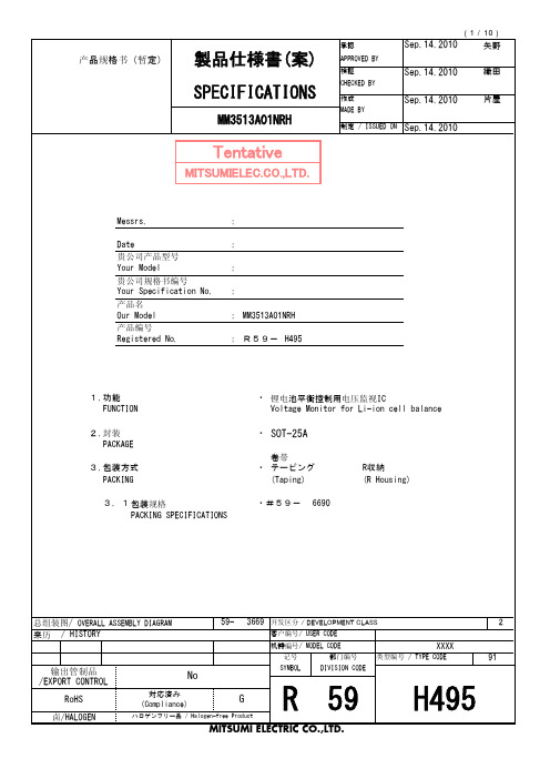
1.功能 FUNCTION
2.封装 PACKAGE
3.包装方式 PACKING
3.1 包装规格 PACKING SPECIFICATIONS
・ 锂电池平衡控制用电压监视IC Voltage Monitor for Li-ion cell balance
・ SOT-25A
卷带 ・ テーピング
(Taping)
℃
9. 电气特性 Electrical characteristics
项目 Parameter 动作输入电压 Operating input voltage
记号 Symbol VDD1
条件 Conditions VDD-VSS
最小 Min.
1.5
标准 Typ.
-
Topr=25℃
最大 Max.
单位 Unit
0.005 0.010 0.015 V C
T=25℃ VDD=3.4V→4.6V
0.20 0.25 0.30 s C
检测延时时间 Detection delay time
tVdet
T=-5~60℃
*4
VDD=3.4V→4.6V
0.18
0.25 0.33
s
C
T=-30~70℃ *4 VDD=3.4V→4.6V
检测电压 Detection voltage
*3
Vdet
T=-5~60℃ R1=330Ω
*4 4.125 4.150 4.175 V C
T=-30~70℃ R1=330Ω
*4 4.105 4.150 4.195 V
C
滞后电压 Hysteresis voltage
*3
Vhys
T=-30~70℃ R1=330Ω
SMSC EVB-USB2514BC 用户手册说明书

Copyright © 2009 SMSC or its subsidiaries. All rights reserved.Circuit diagrams and other information relating to SMSC products are included as a means of illustrating typical applications. Consequently, complete information sufficient for construction purposes is not necessarily given. Although the information has been checked and is believed to be accurate, no responsibility is assumed for inaccuracies. SMSC reserves the right to make changes to specifications and product descriptions at any time without notice. Contact your local SMSC sales office to obtain the latest specifications before placing your product order. The provision of this information does not convey to the purchaser of the described semiconductor devices any licenses under any patent rights or other intellectual property rights of SMSC or others. All sales are expressly conditional on your agreement to the terms and conditions of the most recently dated version of SMSC's standard Terms of Sale Agreement dated before the date of your order (the "Terms of Sale Agreement").The product may contain design defects or errors known as anomalies which may cause the product's functions to deviate from published specifications. Anomaly sheets are available upon request. SMSC products are not designed, intended, authorized or warranted for use in any life support or other application where product failure could cause or contribute to personal injury or severe property damage. Any and all such uses without prior written approval of an Officer of SMSC and further testing and/or modification will be fully at the risk of the customer. Copies of this document or other SMSC literature, as well as the T erms of Sale Agreement, may be obtained by visiting SMSC’s website at . SMSC is a registered trademark of Standard Microsystems Corporation (“SMSC”). Product names and company names are the trademarks of their respective holders.SMSC DISCLAIMS AND EXCLUDES ANY AND ALL WARRANTIES, INCLUDING WITHOUT LIMITATION ANY AND ALL IMPLIED WARRANTIES OF MERCHANTABILITY, FITNESS FOR A PARTICULAR PURPOSE, TITLE, AND AGAINST INFRINGEMENT AND THE LIKE, AND ANY AND ALL WARRANTIES ARISING FROM ANY COURSE OF DEALING OR USAGE OF TRADE. IN NO EVENT SHALL SMSC BE LIABLE FOR ANY DIRECT, INCIDENTAL, INDIRECT,SPECIAL, PUNITIVE, OR CONSEQUENTIAL DAMAGES; OR FOR LOST DATA, PROFITS, SAVINGS OR REVENUES OF ANY KIND; REGARDLESS OF THE FORM OF ACTION, WHETHER BASED ON CONTRACT; TORT; NEGLIGENCE OF SMSC OR OTHERS; STRICT LIABILITY; BREACH OF WARRANTY; OR OTHERWISE; WHETHER OR NOT ANY REMEDY OF BUYER IS HELD TO HAVE FAILED OF ITS ESSENTIAL PURPOSE, AND WHETHER OR NOT SMSC HAS BEEN ADVISED OF THE POSSIBILITY OF SUCH DAMAGES.EVB-USB2514BC Evaluation Board Revision AUser GuideEVB-USB2514BC Evaluation Board Revision A User GuideRevision 0.3 (05-19-09)2SMSC EVB-USB2514BC Revision A1 OverviewThe SMSC USB2514B MultiTRAK™ is a Low-Power, Full-Featured, OEM configurable, Hi-Speed USB 2.0 compliant hub with four downstream ports. Each of these downstream ports in the USB2514B device is capable of supporting battery charging. The EVB-USB2514BC Evaluation Board demonstrates a standalone application for the hub with all the features listed below and demonstrates advanced power saving options and configurable port assignments.1.1 Features36-pin QFN RoHS compliant package.Four USB 2.0 downstream hub ports with individual port power and over-current sense (OCS). Hi-Speed (480 Mbps), Full-Speed (12 Mbps), and Low-Speed (1.5 Mbps) compatible. USB Battery Charging is supported on downstream USB Port 1 to a full 1.5 A.USB Battery Charging is supported on all other downstream USB ports to 500 mA (optional). (In actual use, the port 5 V path, port power controllers, and OCS circuits must be chosen to fully support the specification [ex., USB Port 1]). Multi-Transaction Translator is enabled.Supports internal default hub configuration. Optionally supports configuration from external EEPROM.Low cost 4-Layer space saving design with two outer signal layers, a power inner layer, and a ground inner layer.Individual port over-current sensing.Individual port power control with LEDs for port power indication. Self-powered operation.Operates from a single voltage (5.0 VDC, regulated) external power supply. Single onboard 3.3 VDC regulator.Red LED indicator for “Active” hub state (optional).EMI suppression provided by selection of capacitors and inner power/ground PCB layers. ESD component footprints provided (optional). Single crystal clock source.Schematics, layout, and bill of materials are available to minimize new product development time.1.2 General DescriptionThe EVB-USB2514BC is an evaluation and demonstration platform featuring the USB2514B Ultra Fast USB 2.0 Hub on a 4-layer RoHS compliant printed circuit board.The EVB-USB2514BC is designed to demonstrate the unique features of this device using a low cost PCB implementation with individual port power control for the downstream USB 2.0 ports. Downstream USB 2.0 port 1 includes a high current port power controller to fully support USB battery charging as a high current walk up port.The EVB-USB2514BC is designed to support internal default configuration settings and an external I 2C ®1 EEPROM (optional) for custom configured functionality. A location is provided for an external I 2C EEPROM device for configuration at U6. Figure 2.1 and Figure 2.2 show the top and bottom level silk screen and copper layers.1.I 2C is a registered trademark of Philips Corporation.EVB-USB2514BC Evaluation Board Revision A User GuideSMSC EVB-USB2514BC Revision A 3Revision 0.3 (05-19-09)2 Hardware Configuration2.1Hardware DescriptionThe EVB-USB2514BC has one onboard regulator, which generates 3.3 VDC from an external 5 VDC regulated power supply. The USB2514B generates its own 1.2 VDC for internal use with on-chip 1.2VDC regulators. The internal 1.2 VDC regulator to the oscillator and the PLL is turned off during suspend to minimize suspend current. The USB2514B consumes power from the 3.3 VDC supply.Downstream port power is distributed by three power switches that consume power from the 5 VDC supply. U2 supplies power to the high current downstream port 1. U1 and U3 supply power to the other three ports at 500 mA. Upstream and downstream port connectors have USB 2.0 compliant decoupling and a separate shield ground.2.1.1Port AssignmentDownstream ports are numbered 1 through 4 with individual port power controllers. The USB2514B allows any or all of the downstream ports to be configured for high current battery USB charging, and the EVB-USB2514BC is designed to demonstrate that feature. Downstream port 1 is assigned as the default battery charging port with a high current port power controller installed.2.1.2USB2514B ConfigurationDefault : The EVB-USB2514B has been set up to support an internal default configuration as determined by the state of the CFG_SEL2, CFG_SEL1, and CFG_SEL0 pins immediately after reset.The vendor ID, product ID, language ID, device ID, and other choices have been set using ROM code defaults.EEPROM Option : The EVB-USB2514B can load configuration from an external two-wire, I 2C EEPROM U6. The EEPROM must be installed at U6, and the configuration option resistors on the CFG_SEL2, CFG_SEL1, and CFG_SEL0 pins changed to enable this option. The EEPROM may be pre-programmed before installation, or be programmed with the USB host using provided SMSC USBDM applications. This option allows access to all of the configuration registers and ID strings for the USB2514B device for detailed functional analysis and exercise as desired. The EVB-USB2514B is compatible with I 2C EEPROMs from several manufacturers. The memory capacity must be at least 512 bytes.2.1.3Powered State LEDAn optional LED (LED5) indicates when +5 VDC power is present.2.1.4Activity LEDAn optional LED (LED6) indicates when the USB2514B is active (configured and not suspended).2.1.5Port Power LEDsLED1, LED2, LED3, and LED4 indicate when port power is available to the associated downstream USB port.2.1.6Connector DescriptionThe EVB-USB2514B has a set of standard USB style connectors, one of type B for the upstream port and four of type A for downstream ports. Power is supplied via a 2.0 mm power jack. Table 2.1 lists all of the connectors. For more details on the pinout of these connectors, please see the EVB-USB2514BC schematics on the CD-ROM included with your EVB-USB2514BC.EVB-USB2514BC Evaluation Board Revision A User GuideRevision 0.3 (05-19-09)4SMSC EVB-USB2514BC Revision A2.1.7Layout ConsiderationsThe EVB-USB2514B is designed on four PCB layers--two signal layers and two supply layers. The PCB layer stackup is shown in Table 2.2. All signals are routed on top and bottom layers. Internal layers are ground and power. Note that the differential signals from the USB2514B match the upstream and downstream port placement simplifying routing of critical signals.Table 2.1 Connector DescriptionCONNECTORTYPE DESCRIPTION J1USB A Downstream USB Port 1J2USB A Downstream USB Port 2J3USB A Downstream USB Port 3J4USB A Downstream USB Port 4J5USB B Upstream USB Port 0J6Power Jack 2.0 mm+5 VDC Power SupplyTable 2.2 PCB layer stackComponent Side Solder mask Layer 1 1.9 - 2.8 mil, finished Pre-preg 4.25 mil, +/- 0.25 mil FR-4Layer 2 -- GND1.3 mil (nominal)Core~24 mil FR-4Layer 3 -- POWER1.3 mil (nominal)Pre-preg 4.25 mil, +/- 0.25 mil FR-4Layer 4 1.9 -2.8 mil, finishedSolder mask Solder SideEVB-USB2514BC Evaluation Board Revision A User GuideSMSC EVB-USB2514BC Revision A 5Revision 0.3 (05-19-09)Component side top layer is shown in Figure 2.1 with silk screen information to identify component locations.Figure 2.1 EVB_USB2514B Top Layer - Component SideEVB-USB2514BC Evaluation Board Revision A User GuideRevision 0.3 (05-19-09)6SMSC EVB-USB2514BC Revision AFigure 2.2 EVB_USB2514B Bottom Layer - Solder SideEVB-USB2514BC Evaluation Board Revision A User GuideSMSC EVB-USB2514BC Revision A 7Revision 0.3 (05-19-09)3 Revision HistoryNAME REVISION LEVEL ANDDATE SECTION/FIGURE/ENTRY CORRECTIONC. JohnsonRev 0.3(05-19-09)Section 1.1, "Features"Changed “Low cost 4-Layer space saving design, two outer signal layers: - power and ground inner layers.” to “Low cost 4-Layer space saving design with two outer signal layers, a power inner layer, and a ground inner layer.”Appended “with LEDs for port powerindication” to “Individual port power control.”Removed redundant item “Port OCS/port power control interface...”Removed unsupported feature “3.3 VDC power LED indicator.”Appended “(optional)” to “Red LED indicator for “Active” hub state.”Changed “Schematics, layout, and bill of materials are included to minimize new product development time.” to “Schematics, layout, and bill of materials are available to minimize new product development time.”Section 1.2, "General Description"Removed the incorrect reference to a socket in the last paragraph.Removed the redundant Figure 1.1.Section 2.1, "Hardware Description"Changed the last sentence into two sentences for clarity.Moved the last sentence of section 2.1.1 to the end of this section.Section 2.1.2, "USB2514B Configuration"Changed the first sentence to “...support an internal default configuration...”Correct a typographical error “U4” to “U6” in the second paragraph.Section 2.1.6, "Connector Description"Correct the last sentence to reference the schematics on the included CDROM.Section 2.1.7, "Layout Considerations"Revise the first sentence punctuation from “... PCB layers , two...” to “... PCB layers -- two...”.EVB-USB2514BC Evaluation Board Revision A User GuideRevision 0.3 (05-19-09)8SMSC EVB-USB2514BC Revision AE. WangRev. 0.2(05-11-09)Per E. Wang: Removed xD-Picture Card disclaimer from Cover Master PageSMSC makes the following part-numbered device available for purchase only by customers who are xD-Picture Card licensees: USB2660. By purchasing or ordering any of such devices, Buyer represents, warrants, and agrees that Buyer is a duly licensedLicensee under an xD-Picture CardTM License Agreement with Fuji Photo Film Co., Ltd., Olympus Optical Co., Ltd., and ToshibaCorporation; and that Buyer will maintain in effect such xD-Picture Card license and will give SMSC reasonable advance notice of any termination or expiration of such xD-Picture Card license, but in no event less than five days advance notice. SMSC may discontinue making such devices available for purchase by Buyer and/ordiscontinue further deliveries of such devices if such xD-Picture Card license shall expire, terminate, or cease to be in force, or if Buyer is or becomes in default of such xD-Picture Card license.VariousAdded hyphen before pin in “#-pin QFN” Downstream = Removed spaces Over-current = Added hyphenation Mbits/s = Changed to MbpsRemoved hyphen between “silk screen” “High Speed” = “Hi-Speed” per USB-IF USB2.0 = USB 2.0Added registered trademark and footnote for I 2C technology.Applied consistent capitalization throughoutApplied hyperlinked cross-referencing Figure 1.1 instead of “Figure 1”Trademarks only and acronyms are only described when first mentioned--all other instances have been deletedVariousA space appears between units and units of measurement per 1.the SI Style Guide,2.The Chicago Manual of Style , and3.Matt Young’s The Technical Writer’s Handbook .Section 1.1, "Features" Removed “Features the USB2514B in a...”Section 2.1, "Hardware Description"“The USB2514B generates is own” now reads “its own”.The phrase “for use using on-chip 1.2 VDC regulators.” now reads “for use with on-chip 1.2 VDC regulators. use with on-chip 1.2 VDC regulators.Added a comma after “U3”.Section 2.1.1, "Port Assignment"Changed “5 Volt power” to “5 volts of power”Changed “battry charging port” to “battery...”NAME REVISION LEVEL ANDDATE SECTION/FIGURE/ENTRYCORRECTIONEVB-USB2514BC Evaluation Board Revision A User GuideSMSC EVB-USB2514BC Revision A 9Revision 0.3 (05-19-09)E. WangRev. 0.2(05-11-09)Section 2.1.2, "USB2514B Configuration"Applied bold formatting to keyword subheadings:1.Default2.EEPROM OptionRemoved “and” before “device ID”.Added a comma after CFG_SEL1 when it appeared in a series.The phrase “are set using...” now reads “have been set using ROM code defaults”Section 2.1.6, "Connector Description"Changed “the connectors” to “these connectors”.Added the following cross-references to the end of the last sentence “see the schematics shown in Figure 2.1 and Figure 2.2”.Figure 2.1 and Figure 2.2Updated Figure titles fromEVB_USB660 and EVB_USB2517 to EVB_USB2514BSection 1.2, "General Description," on page 2Per E. Wang:“Customized configured” now reads “custom configured”.Per T. Phan:1.References to 1.8 V have been changed to 1.2 V (3 instances)2.The first paragraph:The EVB-USB2514BC is an evaluation and demonstration platform featuring theUSB2514B Ultra Fast USB 2.0 Hub, Flash Media Controller, and Protocol Bridge Combo on a 4-layer RoHS compliant printed circuit board.now reads:The EVB-USB2514BC is an evaluation and demonstration platform featuring theUSB2514B Ultra Fast USB 2.0 Hub on a 4-layer RoHS compliant printed circuit board.Per C. Johnson:3.Deleted the third paragraph:The EVB-USB2514BC is compatible with Microsoft Vista, Windows XP , Windows ME, Windows 2k SP4, Apple OSx and Linux Mass Storage Class Drivers.C. JohnsonRev. 0.1 (04-09-09)Initial document creation.NAME REVISION LEVEL ANDDATE SECTION/FIGURE/ENTRY CORRECTIONEVB-USB2514BC Evaluation Board Revision A User Guide ArrayRevision 0.3 (05-19-09)10SMSC EVB-USB2514BC Revision A。
PLM20K44产品说明书

2012-12-21
U516
x
U510
x
U512, , U514, U505
x
U506
x
U508, U509
x
U507
x
U900
x
U902
x
D3, D304, D307, D504
x
D303, D305
27V.25W5%SOT-23 COAEXPFC52-A01 COAEXPFC70-A01 COAEXPFC70-A03
COCIPI4X2-A01
COSP05FB 6R8.33W5%1206 2R7.33W5%1206 10K.125W1%0805
22n630VMKP7.5 T50WFETD29 T16A400-5x20AL T3A15400-5x20
Q3, Q7, Q307, Q308, Q508 Q4, Q5, Q8, Q9, Q400, Q401, Q403, Q507, Q404, Q12
Q408
Q11 Q10, Q500 Q509
Q505 U300, U401
U407, U408, U504
Ic Operational Amplifier Lm833 SOIC Narrow body Ic dual gate driver FAN3224CMX SOIC-8 Pulse Width Modulator PFC type 1 rev.03a Final Assembly 01
Ic Comparator Lm339D
Ic Digital Isolator SI8441-C Ic Inverting Scmitt trigger 74AHC1G14 SOT353-1 Diode Signal Bas21 SOT-23 Diode Power 1n4006 Diode Zener 6V2 .225W 2% SOT-23
不干胶贴签机URS标准
不干胶贴签机URS标准1. 综述1.1目的本文件对不干胶贴签机的设计、制造、控制系统、检查和测试、文件、包装和交付做了说明。
供应商按照此文件进行设备的设计、制造、检查和测试、包装和交付、调试FAT(包括试运行与验证)、最终检查等活动。
供应商提供的货物应完全符合本文件要求及相关标准和规范,并须对需方所提供的URS负保密责任。
1.2工艺过程该机将被用于小容量注射制剂的贴标工序,安瓿瓶通过贴标机上料台人工上料,通过本URS的贴标机完成安瓿瓶的贴标工艺过程。
该机应能高速度及高稳定性地完成不同规格安瓿瓶的贴标任务。
2.工艺用户需求2.1法规标准中国相应的规范和新版GMP要求中国安全、质量、环保法规2.2工作时间供应商应保证设备在下列条件下正常连续运行:有效工作周数:每年48周每周工作天数:5天每天运行时间:12小时2.3工作环境温度:0~40℃湿度:30~95%2.4物料规格安瓿瓶:1ml、直径: mm、高度: mm标签:(L) *(W) mm、透明不干胶标签瓶托:(L) *(W) *(H) mm、每托放支药品3.供应服务范围所有本文件说明的设备、附属零部件、辅助设备等整套装置;保障设备性能良好所必须的所有部件。
所有原材料、零部件、设备、电气及控制系统都要保留原始资料,并且必须经过检查并形成文件。
供货商应对其提供的材料、零部件和设备及其可追溯性负全部责任。
提供安装调试、验证、试运行所需要的所有配件、仪器和工具。
4.技术要求4.1生产工艺要求4.2厂房设施及公用系统要求4.3机械部分要求4.4电控部分要求4.5 EHS要求5.服务要求5.1FAT要求5.2包装运输要求5.3文件资料要求5.4备品零件要求5.5安装调试要求5.6 SAT要求5.7培训要求5.8 保修要求6.项目实施要求6.1质量项目计划6.2制造进度。
QAlibria QMS-C-AS-051-02 商品说明书

Multi-Touch System Dashboard
• Visual representation of system configuration
• Intuitive control • Quick access to system components
Handy VNA Tools
• S-parameter measurements • QuickView graphical tool for data
verification
Automatic Configuration of Probes, Substrates and Standards
• Easy and error-free operation for beginners
Configuration Monitor
• Tracking of the VNA type, probe configuration and calibration methods
Probe Configuration Tools
• Probe type and orientation • Intuitive VNA port mapping • Recently used models
Quick Access Widgets
• Calibration reference plane • Standards models • re-configuration
Intelligent Hardware Recognition
• Automated reconfiguration of the automated/manual work flow
• No need to configure VNA and probe system
MCP2517xFD CAN FD母板商品说明书
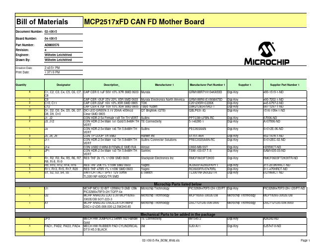
PIC32MX470F512H-120/PT Digi-Key
PIC32MX470F512H TQFP-64
U2
MCHP ANALOG LDO 3.3V MCP1826S- Microchip Technology
MCP1826S-3302E/DB
Microchip Technology
3302E/DB SOT-223-3
Bill of Materials
Document Number: 02-10615
Board Number:
04-10615
Part Number: Revision: Engineer: Drawn By:
ADM00576 4 Wilhelm Leichtfried Wilhelm Leichtfried
Digi-Key Digi-Key
Digi-Key
Digi-Key Digi-Key
Digi-Key Digi-Key
Digi-Key
Digi-Key Digi-Key Digi-Key
Microchip Parts listed below
U1
MCHP MCU 32-BIT 120MHz 512kB 128k Microchip Technology
02-10615-R4_BOM_Web.xls
Page 2
CON HDR-2.54 Male 1x1 Gold 5.84MH TH TE Connectivity
5-146280-1
VERT
CON HDR-2.54 Male 1x2 Tin 5.84MH TH Sullins Connector Solutions
PREC002SAAN-RC
国家电子NI 9227 四通道、五臂、24位、同时、渠道间隔离模拟输入模块操作指南和规格说明书
Caution Ensure that hazardous voltage wiring is performed only by qualified personnel adhering to local electrical standards. Caution Do not mix hazardous voltage circuits and human-accessible circuits on the same module. Caution Make sure that devices and circuits connected to the module are properly insulated from human contact.
Services /services
2 | | NI 9227 Operating Instructions and Specifications
Safety Guidelines
Operate the NI 9227 only as described in these operating instructions.
Figure 5. Input Circuitry for One Channel of the NI 9227
AI+C
Amplifier Prefilter
NI 9227
NI 9227 Operating Instructions and Specifications | © National Instruments | 9
Related Information
SAFEB1G57KE0F00R15
Criteria No visible damage should be induceபைடு நூலகம் and the electrical performance should meet Table 1.
PCB R10 5 Supporter Part 45 2
J T
(2) (3)
(0.20)
0.6max.
5-0.325±0.050
(2) (1) (5)
(3)
2-0.25±0.05
(0.075)
Marking : Laser Printing : Manufacturer symbol : EIAJ Code Terminal (Surface) : Au thickness 0.5...1.0m (Typ. 0.6m) Terminal (Base) : Ni thickness 2.0...6.0m (Typ. 4.0m) Terminal Number (1) : Unbalance Port (4) : Unbalance Port Others : Ground Weight : 3.21.0mg Coplanarity : 0.1mm max. Unit : mm
1575.5MHz 1.3dB max. 40 dB min. 41 dB min. 40 dB min. 40 dB min. 40 dB min. 37 dB min. 1.1 dB min. 40 dB min. 43 dB min 44 dB min 43 dB min 43 dB min. 45 dB min 40 dB min 30 dB min. 0.6dB max. 1.7 max.
MM3474D01VBE_100709_(中文)

4. 概要 / Outline・MM3474系列概要MM3474系列采用高耐压CMOS工艺,对于2次用锂电池/聚合物电池的过充电,过放电及过电流能起到保护作用的IC.当3节~5节的锂电池/聚合物电池在发生过充电,过放电及过电流时可起到一定的保护。
另外,将MM3474进行级联,可对应6节以上电池的应用。
IC内部由电压检测器,基准电压源,OR电路,不感应时间设定电路,逻辑电路等构成。
・过充电保护功能电池V1 到电池V5,只要其中一节电池的电压在过充电保护电压以上时,经过COV端子上所连接的电容值来设定的不感应延时时间后,与外围下拉电阻相连接的OV端输出:高阻抗/"Hi impedance",充电控制用Nch MOS FET为OFF,充电被停止。
当电池V1到电池V5其中每一节的电压都在过充电解除电压以下时,OV端子输出高电平H,过充电保护状态解除。
・过放电保护功能电池V1到电池V5,只要其中一节电池的电压在过放电保护电压以下时,经过CDC端子上所连接的电容值来设定的不感应延时时间后,DCHG端子输出低电平L ,放电控制用Nch MOS FET 为OFF,放电被停止。
当电池V1到电池V5其中每一节的电压都在放电再开电压以上时,DCHG端子输出高电平H,过放电保护状态解除。
・过电流・短路保护功能在放电可能状态下,由于负载短路等原因,CS端子的电压在过电流保护电压以上、短路保护电压以下时,此状态为过电流保护状态。
CS端子电压在短路保护电压以上时,此状态为短路保护状态。
过电流及短路保护后,经过COL1端子上所连接的电容值来设定的不感应延时时间后DCHG端子输出低电平L,放电控制用Nch MOS FET为OFF。
放电被停止。
过电流及短路保护状态的解除,是通过开放负载来进行的,负载开放后,通过IC内部的下拉电阻,V-端子的电压在过电流解除V-端子电压以下时,DCHG端子输出高电平H,过电流及短路保护状态解除。
威亚维光纤清洁棒选型指南说明书

Selection Guide Fiber Cleaning Tips and Adapters FCLT-U12-MA FCLT-U12X FCLT-U25CleanBlast Tip for SC Bulkheadssupport both PC/UPC and APC polish types with the same tip. Some of the tips are also used in conjunction with a guide, as shown in the images below.Manufacturer: Product Name:VIAVI CLEANBLAST MT BULKHEAD TIP MATING ADAPTER SC SC FCLT-SCX CleanBlast Tip for SC Bulkheads, HardenedE2000CleanBlast Tip for FC BulkheadsCleanBlast Tip for LC BulkheadsCleanBlast Tip for LC Bulkheads, AngledCleanBlast Tip for MU BulkheadsCleanBlast Tip for MPX BulkheadsCleanBlast Tip for MT Ferrule Bulkheads(unconnectorized)SCALE FCLT-MTP CleanBlast Tip for MPO BulkheadsCleanBlast Adapter for MT Ferrule(unconnectorized)Note: Requires FCLT-MTPCleanBlast Tip for MPO Bulkheads, AngledVIAVI CLEANBLAST MT BULKHEAD TIP MATING ADAPTER Manufacturer Part Number: T-MTP-MA Ribbon T-HMFOC-P Ribbon CleanBlast Tip for HMFOC Drop T erminal Ports T-HMFOC-R Ribbon FCLT-HMFOC-R CleanBlast Tip for HMFOC Drop T erminal PortsFCLT-EXBEAM-1CleanBlast Tip for FibrecaST Jr/Sr Expanded Beam SCALE 2:1FBPT-BAP3-125CleanBlast Tip for BAP3 GuidesCleanBlast Tip for BAP4 GuidesFCLT-C130CleanBlast Tip for C130CleanBlast Tip for 29504/14 and 29504/15 T Note: Cleans Both Pins and SocketsCleanBlast Tip for 29504/4 and 29504/5 T Note: Cleans Both Pins and SocketsManufacturer: Product Name: VIAVI CLEANBLAST MT BULKHEAD TIP MATING ADAPTER FCLT-MT-MA © 2020 VIAVI Solutions Inc. Product specifications and descriptions in this document are subject to change without notice. T-MIL2-A6Mil/Aero Angled 60 DegreesNote: Cleans Both Pins and Sockets T-MIL2-CPA Mil/Aero CleanBlast Tip for Use with Glenair T estCleanBlast Tip for 1.25mm LuxCis T erminiNote: Cleans Both Pins and SocketsCleanBlast Tip for 38999 with MT FerrulesNote: Requires FBPT-MT999 GuidesCleanBlast Tip for Radiall Quadrax Size 8 -CleanBlast Tip for Radiall Quadrax Size 8 -CleanBlast Tip for TFOCA-II Connectors(includes Guide)or call 1-844-Go VIAVI (+1-844-468-4284).。
Z-Wave蓝牙控制器操作手册说明书
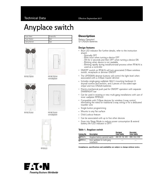
DescriptionBattery Operated (2) CR2025 BatteriesDesign features•Blue LED indicator [for further details, refer to the instruction sheet]:- Normally OFF- Blink once when turning a device OFF- ON for 2 seconds and then OFF when turning a device ON - Blinking when device is not readable - B linking rapidly during install/uninstall process when RF9575 isused as a controller •ON/OFF switch on RF9575 will turn associated Z-Wave wireless switch, receptacle or dimmer ON/OFF•The UP/DOWN dimmer buttons will control the light level when associated with a Z-Wave master dimmer•Includes single-gang wallplate (9521) mounting hardware (2 drywall screws and anchors, and 2 pieces of two-sided tape strips) and two CR2025 batteries•Electro-mechanical push pad for ON/OFF operation with separate DIM/BRIGHT bar•Can be used in existing or new multi-gang installations with use of inner wallplate (RFBS22)•Compatible with Z-Wave devices for wireless 3-way control,eliminating the need for traditional 3-way wiring or for a dedicated traveller wire•Single button programming • Mounts to any flat surface • Child Lockout feature• Can be associated with up to five other devices•Goes into Sleep Mode to reduce power consumption & extend battery life (LED indicator is OFF)Anyplace switchCatalog No.DescriptionDesigner Color SuffixDecorator Color SuffixRF9575__Anyplace battery operated switch AW, DS, SG, WS DBK, DLA, DWRFBS22__Inner wallplate for multi-gang installation——RF9575DWRF9575DW w/wallplateCompliances, specifications and availability are subject to change without notice.Project Name:Prepared By:Project Number:Date:Catalog Number:Type:T able 1.Anyplace switchRFBS22RF9575AWRF9575AW w/wallplate2EATON /wiringdevices Technical DataEffective September 2017Anyplace switchCompliances, specifications and availability are subject to change without notice.Catalog No.Anyplace Switch RF9575PerformancePower: (2) CR2025 batteries (supplied)Expected battery life: + 1 yearUses 300 series Z-Wave chip @40KbsNote: Not used as a repeater in RF mesh network.Performance Consideration A Z-Wave enabled device must be within 60 feet of another Z-Wave enabled device to participate in a Z-Wave wireless mesh network. Any one dimmer or switch can be associated with up to 5 devices (dimmers, switches, receptacles or plug-in modules).Installation & Programming Please reference the instruction sheet included with product for installation and programming. For system programming, see the user manual provided with your controller. Both are also accessible online at /wiringdevicesTesting & Code Compliance cULus Listed Appliance Control 38DS, NOM Certified, Complies with FCC Part 15, Class B, Z-Wave Compliant CertifiedTerminationsRequires RFBS22 inner wallplate for multi-gang installations. Note: Anyplace RF battery operated switch shall not be mounted to an electrical box.Material Characteristics Flammability: Meets Flammability Rating: V2 per UL94 Temperature Rating: 32ºF to 104ºF (0ºC to 40ºC)Warranty2 year limited product warrantyAnyplace switch controls Z-Wave receptacles, switches or dimmers to provide remote ON/OFF/DIM/BRIGHT control. This provides other programmable functions when used with Z-Wave compliant products. Anyplace switch is intended to manually control other Z-Wavedevices through association with or without a controller. Anyplace switch utilizes two CR2025 batteries and mounts flush to the wall. No new wiring is required.ApplicationsProject Name:Prepared By:Project Number:Date:Catalog Number:Type:T able 2. SpecificationsT able 3. Color Ordering InformationFor ordering devices, include Catalog no. followed by the Color suffix: AW (Alpine White), DS (Desert Sand),SG (Silver Granite), WS (White Satin), DBK (Decorator Black), DLA (Decorator Light Almond), DW (Decorator White).Black)Light Almond)(Decorator White)Product DimensionsFigure 1. RF9575 Decorator seriesFigure 2. RF9575 Designer seriesTechnical DataEffective September 2017Anyplace switchElectrical Sector 203 Cooper CirclePeachtree City, GA 30269United States /wiringdevicesElectrical Sector Canada Operations 5925 McLaughlin RoadMississauga, Ontario, L5R 1B8CanadaEatonCanada.ca/wiringdevicesElectrical Sector Mexico Operations Carr. Tlalnepantla -Cuautitlan Km 17.8 s/n Col. Villa Jardin esq.Cerrada 8 de MayoCuautitlan, Mexico CP 54800Mexico Eaton.mx/wiringdevices Eaton is a registered trademark. All other trademarks are property of their respective owners.Eaton1000 Eaton Boulevard Cleveland, OH 44122United States © 2017 EatonAll Rights Reserved Printed in USAPublication No. TD610046EN September 2017Project Name:Prepared By:Project Number:Date:Catalog Number:Type:Certifications & CompliancesKEY:cULusFCCRFBS22••Related ProductsRF9501AW, RF9540-NDW, RFTR9505-T, RFLDMZ-Wave wireless products。
- 1、下载文档前请自行甄别文档内容的完整性,平台不提供额外的编辑、内容补充、找答案等附加服务。
- 2、"仅部分预览"的文档,不可在线预览部分如存在完整性等问题,可反馈申请退款(可完整预览的文档不适用该条件!)。
- 3、如文档侵犯您的权益,请联系客服反馈,我们会尽快为您处理(人工客服工作时间:9:00-18:30)。
・特長・過充電、セルバランス、過放電、過電流検出回路内蔵FEATURESOvercharge detection voltage circuit included ・断線検出回路内蔵Disconnection detect circuit included ・レギュレータ機能内蔵Regulator function included ・・・#59 -PACKING SPECIFICATIONS得意先コード / USER CODE機種コード / MODEL CODE決裁ISSUED BY担当木村大APPROVED BY PACKINGテーピングTaping PACKAGE 梱包検認FUNCTION記号3.6754開発区分 / DEVELOPMENT CLASS 輸出規制品/EXPORT CONTROLNo部門コード3-1.梱包仕様1.MM3575A02VBE機能製品仕様書(案)SPECIFICATIONSリチウムイオン電池 3~5直保護CHECKED BY Li-ion Battery protection IC (For 3~5 cell in series)2制定/ISSUED ONTSOP-24AB 収納B Housing91タイプコード / TYPE CODExxxx1-1.59R RoHS対応済み (Compliance)G2.パッケージSYMBOLDIVISION CODE 3来歴HISTORY変更内容CHANGED CONTENT 新規作成。
New making 1.ブロック図修正The block diarram is corrected 2.充電過電流検出電圧精度修正Charging overcurrent detection voltage accuracy is corrected3.SDC 解除電流仕様変更SDC release currentis changed 4.SDC 端子電流仕様変更SDC input current is changed 5.SOC 解除電流仕様変更SOC release current is changed 6.SOC 端子電流仕様変更SOC input current is changed 7.カレントリミット検出電圧削除Current limit detection voltage is deleted 8.COC 端子容量係数削除、遅延時間特性追加COC pin capacity coefficient is deleted COC pin delay time characteristic is added 9.応用回路例修正Application circuit is correctedDRAFT.May 8,2013CHARGE DATEDRAFT.HISTORY日付Nov 16,2012担当木村大木村大1ブロック図BLOCK DIAGRAMピン配置PIN CONFIGURATION5.4.1端子説明TERMINAL EXPLANATIONSInput terminal connected to discharge voltage. Detected load connection.6.1211101端子No.PIN No.INPUT / OUTPUTIC の電源入力端子。
端子名入出力説明PIN NAME PIN DESCRIPTIONVDDCharge control output terminal. Output type is Pch open drain.充電制御出力端子。
Pch OPEN ドレイン出力。
The input terminal of the power supply of IC.INPUTThe control terminal of output over charge detection.過充電検出出力制御端子。
・I SOC <I SOC LINPUTInput terminal connected to charger negative voltage. Detected charger connection.:”Hi impedance”:”High”・過充電時(Overcharge mode)・通常時(Normal mode)過電流検出端子です。
CS1-CS2間に接続した抵抗で過電流を検出します。
検出すると、DCHG 端子から"L"レベルを出力し、大電流が流れることを防ぎます。
Input of overcurrent detection. Detected overcurrent by sense resistor between CS1 pin and CS2 pin. And then the DCHG terminal outputs low level, and it protects from large current discharging.INPUTREG_INOUTPUT DRIVE INPUT CS2過電流検出回路の基準端子です。
Common terminal of overcurrent detection circuit.レギュレータ用FET のドライブ端子。
The drive terminal of FET for regulator.INPUTThe control terminal of output over discharge detection.過放電検出出力制御端子。
充電器マイナス電位入力端子。
充電器の接続状態を検出します。
:”High”・過放電時(Overdischarge mode)レギュレータ電圧のインプット端子。
The input terminal of regulator voltage.OUTPUTSOC 2INPUTSDC 3OV 5VM247放電過電流、充電過電流検出/復帰の遅延時間設定端子です。
VDD 端子-COC 端子間にコンデンサを接続する事により遅延時間を設定することができます。
A terminal which sets delay time of discharging overcurrent and charging overcurrent detection/release.It is able to set delay time by connecting a condenser between VDD and COC terminals.INPUTVM16OUTPUTDCHG 放電電位入力端子。
負荷の接続状態を検出します。
8INPUTCS19INPUTCOC ・通常時(Normal mode)・I SOC >I SOC HOV :放電禁止(charge prohibition)=”Hi-impedance”OV :通常動作(Normal mode)DCHG :放電禁止(discharge prohibition)=”Low”DCHG :通常動作(Normal mode)・I SDC <I SDC L・I SDC >I SDC HDischarge control output terminal. Output type is CMOS.放電制御出力端子。
V3とVSS の間のCMOS 出力。
:”Low”V1 cell balance control output terminal. Output type is CMOS.・通常時(Normal mode):”Low”・検出時(Detect mode):”High”V2 cell balance control output terminal. Output type is CMOS.・通常時(Normal mode):”Low”・検出時(Detect mode):”High”V3 cell balance control output terminal. Output type is CMOS.・通常時(Normal mode):”Low”・検出時(Detect mode):”High”V4 cell balance control output terminal. Output type is CMOS.・通常時(Normal mode):”Low”・検出時(Detect mode):”High”V5 cell balance control output terminal. Output type is CMOS.・通常時(Normal mode):”Low”・検出時(Detcet mode):”High”OUTPUTOUT31914OUTPUTOUT115PIN NAMEINPUT / OUTPUT21INPUTV320INPUTV524OUTPUTOUT523INPUTV422161817OUT2OUTPUTOUTPUTOUT4PIN DESCRIPTIONINPUTV2INPUTV1INPUTVSS VSSV2VDD端子No.端子名入出力説明13PIN No.IC のグラウンド入力端子。
V1セルのローサイド電圧の入力端子。
The input terminal of the negative voltage of V1 cell.The input terminal of the ground of IC.V1セルのセルバランス制御端子V1セルのハイサイド電圧及びV2セルのローサイド電圧の入力端子。
The input terminal of the positive voltage of V1 cell, and the negative voltage of V2 cell .V2セルのセルバランス制御端子V3セルのハイサイド電圧及びV4セルのローサイド電圧の入力端子。
V5セルのセルバランス制御端子INPUTSEL This pin is for changing function for 3cell in series or 4cell in series , 5cell in series.V2セルのハイサイド電圧及びV3セルのローサイド電圧の入力端子。
The input terminal of the positive voltage of V2 cell, and the negative voltage of V3 cell .V3セルのセルバランス制御端子3,4,5直の切り替え端子。
3Cell in series (Connect V5,V4 and V3 terminal )3直監視(V5-V4-V3端子間ショート)4Cell in series (Connect V5 and V4 terminal)4直監視(V5-V4端子間ショート)5Cell in series入力電圧 / Input voltageV5セルのハイサイド電圧入力端子。
