RB-3.31.8D中文资料
RB说明书中文版

R B说明书中文版Document serial number【NL89WT-NY98YT-NC8CB-NNUUT-NUT108】新型环保制冷剂R415B (原THR01b)产品说明书目录1. R415B产品的理化指标2. R415B产品的主要物性参数3. R415B产品的环境性能4. R415B产品的热工性能5. R415B产品的安全性能6. R415B产品的直接充灌性能7. R415B产品的使用技术和充灌指南8. 技术协助附表1、充注用R415B的饱和性质表附表2、充注用R134a的饱和性质表说明:此版本说明书,系根据近年来实际应用需要,对原说明书作相应的修订和补充。
使用R415B时,请以此版本为准。
今后还将根据实际需要,不定期地出版新版本说明书。
R415B(原THR01b)可直接充灌于汽车空调中替代R134a。
R415B是美国制冷供暖空调工程师学会(ASHRAE)授予THR01b的国际编号。
R415B于1998年获美国国家环保局“重要的新替代物”(SNAP)项目的认可。
R415B被我国国家环保总局评为“1999年A类国家重点环境保护实用技术”,是2004年国家环保总局推荐的消耗臭氧层物质(ODS)替代品。
R415B的主要特点是:⑴环保性能好;⑵安全性能好。
无毒、不易燃;⑶热工性能好。
节能,制冷性能好,降温速度快;⑷直接充灌性能好。
不必改动原R134a制冷空调系统的部件和生产线,可直接充灌,转轨费用低。
1. R415B产品的理化指标外观:无色透明,不混浊气味:无异臭纯度:≥%水份:≤10mg/kg酸度(以HCl计):≤kg蒸发残留物:≤50mg/kg2. R415B产品的主要物性参数R415B为近共沸的二元混合物。
表1比较了R415B与R12和R134a的主要物性参数,可知R415B的相变汽化潜热大、临界温度高、导热系数大和粘度小等几个特征使R415B的制冷系统充装量更少、制冷速度更快、换热和流动效果更好。
D31A中文资料
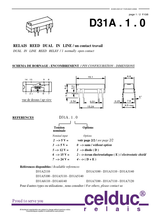
CARACTERISTIQUES PHYSIQUES / GENERAL SPECIFICATIONS T° de stockage / storage t° range T° de fonctionnement / working t° range Tenue aux vibrations ( 30 à 4000 Hz ) / vibrations Résistance au choc ( 11 ms ) / shocks Elévation de température / thermal resistance - 40°C + 105°C - 40°C + 70°C 30 g 100 g 85°C/W
relachement ( sans diode surpresseuse ) / release time typ ( without diode ) 50 µs Résistance de contact initiale / contact résistance 150 m max Fiabilité / life expenctancy typ 10 W --> 106 op 50 V - 100mA --> 1.107 op durée de vie mécanique / mecanical life expectancy --> 1. 109 op
Proud to serve you
All technical caracteristics are subject to change without previous notice. Caractéristiques sujettes à modifications sans préavis.
r
200 500 1000 2150 2150
最新TIA-EIA 568 B.3 中文版资料

TIA 568 B.3光纤标准1. 介绍1.1 目的本标准制定了光纤布线系统(如:线缆、连接头等)所用器件及传输质量的要求。
线缆指50/125μm、62.5/125μm多模光缆和单模光缆。
1.2 标准分类根据EIA工程出版物EP-7B,标准分为两类:强制性标准和建议性标准。
本标准中用“必须”表述强制性标准,用“应该”、“可以”或“最好”表述建议性标准。
强制性标准通常用于安全、性能、管理和兼容性方面的要求,它们做出的规定是对布线系统的最低要求。
建议性标准提高了对布线系统的要求,使布线系统能在预期的应用中稳定工作。
文本、表格和图形中的注释、强调提供了有信息价值的建议。
1.3 美国惯用尺寸与公制尺寸的转换在本标准中多数的公制尺寸是美国惯用单位的转换值,例如:100毫米(mm)是4英寸。
1.4 本标准适用期限标准中的条款会修订、更新以适应建筑技术和通讯技术的发展。
2. 范围2.1 适用性本标准针对布线中用到的光纤器件(如:光缆、连接头、连接硬件、光纤跳线和现场测试设备)规定了最低要求。
2.2 标准参考制定本标准参考下段文本中所列标准,所列标准在公布时已核对过。
所有标准都与版本关联,以本标准为依据的一方应该调查使用所列标准的最新版。
ANSI和TIA记录了他们出版的最新的国家标准。
·ANSI/EIA/TIA-455-A-1991 标准化测试程序,针对光纤、光缆和变频器、传感器、连接与终端设备,及其他光纤组件等;·ANSI/ICEA S-83-596-1994 建筑物内光缆;·ANSI/ICEA S-87-640-2000 室外通信光缆;·ANSI/TIA/EIA-526-7-1998 安装单模光缆的光损耗测量PLANT-OFSTP-7;·ANSI/TIA/EIA-526-14-A-1998 安装多模光缆的光损耗测量PLANT-OFSTP-14A;·ANSI/TIA/EIA-598-A-1995 光缆颜色编码;·ANSI/TIA/EIA-604-3-1997 FOCIS 3光纤连接器件的匹配标准;·ANSI/TIA/EIA-606-1993 商业建筑物电信基础构造的管理标准。
6.车型数据库-广汽本田奥德赛RB3
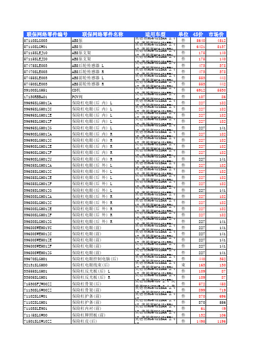
奥德赛HG6481BAA 2.4 AT件 奥德赛HG6481BBA 1495 2.4 949 AT 奥德赛HG6481BAA 2.4 AT件 奥德赛HG6481BBA 1208 1101 2.4 AT 奥德赛HG6481BAA 2.4 AT件 奥德赛HG6481BBA 1495 1196 2.4 AT 奥德赛HG6481BAA 2.4 AT件 奥德赛HG6481BBA 1495 1196 2.4 AT 奥德赛HG6481BAA 2.4 AT件 奥德赛HG6481BBA 1495 2.4 949 AT 奥德赛HG6481BAA 2.4 AT件 奥德赛HG6481BBA 47 2.4 38 AT 奥德赛HG6481BAA 2.4 AT件 奥德赛HG6481BBA 47 2.4 38 AT 奥德赛HG6481BAA 2.4 AT件 奥德赛HG6481BBA 47 2.4 38 AT 奥德赛HG6481BAA 2.4 AT件 奥德赛HG6481BBA 47 2.4 38 AT 奥德赛HG6481BAA 2.4 AT件 奥德赛HG6481BBA 47 2.4 30 AT 奥德赛HG6481BAA 2.4 AT件 奥德赛HG6481BBA 47 2.4 30 AT 奥德赛HG6481BAA 2.4 AT件 奥德赛HG6481BBA 47 2.4 30 AT 奥德赛HG6481BAA 2.4 AT件 奥德赛HG6481BBA 47 2.4 30 AT 奥德赛HG6481BAA 2.4 AT件 奥德赛HG6481BBA 47 2.4 30 AT 奥德赛HG6481BAA 2.4 AT件 奥德赛HG6481BBA 47 2.4 30 AT 奥德赛HG6481BAA 2.4 AT件 奥德赛HG6481BBA 42 2.4 34 AT 奥德赛HG6481BAA 2.4 AT件 奥德赛HG6481BBA 42 2.4 34 AT 奥德赛HG6481BAA 2.4 AT件 奥德赛HG6481BBA 299 2.4 239 AT 奥德赛HG6481BAA 2.4 AT件 565 452 奥德赛HG6481BAA 2.4 AT件 奥德赛HG6481BBA 662 2.4 424 AT 奥德赛HG6481BAA 2.4 AT件 奥德赛HG6481BBA 565 2.4 364 AT 奥德赛HG6481BAA 2.4 AT件 奥德赛HG6481BBA 73 2.4 58 AT 奥德赛HG6481BAA 2.4 AT件 奥德赛HG6481BBA 73 2.4 58 AT 奥德赛HG6481BAA 2.4 AT件 奥德赛HG6481BBA 160 2.4 128 AT 奥德赛HG6481BAA 2.4 AT件 奥德赛HG6481BBA 160 2.4 128 AT 奥德赛HG6481BAA 2.4 AT件 2346 1877 奥德赛HG6481BAA 2.4 AT件 2346 1877 奥德赛HG6481BAA 2.4 AT件 奥德赛HG6481BBA 2346 1495 2.4 AT 奥德赛HG6481BAA 2.4 AT件 奥德赛HG6481BBA 2346 1495 2.4 AT 奥德赛HG6481BAA 2.4 AT件 1354 1083 奥德赛HG6481BAA 2.4 AT件 1354 1083 奥德赛HG6481BAA 2.4 AT件 奥德赛HG6481BBA 1354 2.4 859 AT 奥德赛HG6481BAA 2.4 AT件 奥德赛HG6481BBA 1354 2.4 859 AT 奥德赛HG6481BAA 2.4 AT件 奥德赛HG6481BBA 488 2.4 390 AT 奥德赛HG6480 2.4 奥德赛HG6480AB 件 789 2.4 奥德赛HG6480B 631 2.4 奥 奥德赛HG6481BAA 2.4 AT件 奥德赛HG6481BBA 789 2.4 505 AT 奥德赛HG6480 2.4 奥德赛HG6480AB 件 556 2.4 奥德赛HG6480B 445 2.4 奥 奥德赛HG6481BAA 2.4 AT件 834 667 奥德赛HG6481BAA 2.4 AT件 奥德赛HG6481BBA 834 2.4 535 AT 奥德赛HG6481BAA 2.4 AT件 奥德赛HG6481BBA 834 2.4 535 AT 奥德赛HG6480B 2.4 奥德赛HG6480BB 件 814 2.4 奥德赛HG6481BAA 651 2.4 奥德赛HG6481BAA 2.4 AT件 奥德赛HG6481BBA 1657 1326 2.4 AT 奥德赛HG6480B 2.4 奥德赛HG6480BB 件 1906 2.4 奥德赛HG6481BAA 1525 2.4 奥德赛HG6481BAA 2.4 AT件 1144 915 奥德赛HG6481BAA 2.4 AT件 奥德赛HG6481BBA 1399 1119 2.4 AT 奥德赛HG6480B 2.4 奥德赛HG6480BB 件 2537 2.4 奥德赛HG6481BAA 1589 2.4 奥德赛HG6481BAA 2.4 AT件 奥德赛HG6481BBA 596 2.4 477 AT
RB731UT108;中文规格书,Datasheet资料
㪈㪇
㪌 㪘㪭㪜㪑㪎㪅㪊㪇㪘
㪇
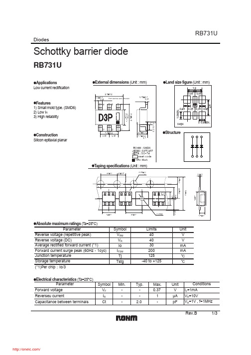
㪠㪝㪪㪤㩷㪛㪠㪪㪧㪜㪩㪪㪠㪦㪥㩷㪤㪘㪧
㪧㪜㪘㪢㩷㪪㪬㪩㪞㪜 㪝㪦㪩㪮㪘㪩㪛㩷㪚㪬㪩㪩㪜㪥㪫㪑㪠㪝㪪㪤㩿㪘㪀
㪉㪇
㪠㪽㫊㫄 㪈㪌
㪏㪅㪊㫄㫊 㪏㪅㪊㫄㫊 㪈㪺㫐㪺
㪈㪇
㪌
㪇
㪈
㪈㪇
㪈㪇㪇
㪥㪬㪤㪙㪜㪩㩷㪦㪝㩷㪚㪰㪚㪣㪜㪪
㪠㪝㪪㪤㪄㪚㪰㪚㪣㪜㩷㪚㪟㪘㪩㪘㪚㪫㪜㪩㪠㪪㪫㪠㪚㪪
㪧㪜㪘㪢㩷㪪㪬㪩㪞㪜 㪝㪦㪩㪮㪘㪩㪛㩷㪚㪬㪩㪩㪜㪥㪫㪑㪠㪝㪪㪤㩿㪘㪀
Symbol Min.
Typ.
Max.
Unit
Conditions
Forward voltage Reverseu current
VF
-
IR
-
-
0.37
V IF=1mA
-
1
μA VR=10V
Capacitance between terminals
Ct
-
2.0
-
pF VR=1V , f=1MHz
Rev.B
㪇㪅㪉
㪘㪭㪜㪑㪇㪅㪇㪏㪊㫅㪘
㪇㪅㪈
㪇
㪠㪩㩷㪛㪠㪪㪧㪜㪩㪪㪠㪦㪥㩷㪤㪘㪧
㪚㪘㪧㪘㪚㪠㪫㪘㪥㪚㪜㩷㪙㪜㪫㪮㪜㪜㪥 㪫㪜㪩㪤㪠㪥㪘㪣㪪㪑㪚㫋㩿㫇㪝㪀
㪚㪘㪧㪘㪚㪠㪫㪘㪥㪚㪜㩷㪙㪜㪫㪮㪜㪜㪥 㪫㪜㪩㪤㪠㪥㪘㪣㪪㪑㪚㫋㩿㫇㪝㪀
RB731U
㪈㪇 㪽㪔㪈㪤㪟㫑
㪈
㪇㪅㪈 㪇
㪌 㪈㪇 㪈㪌 㪉㪇 㪉㪌 㪊㪇 㪊㪌
㪩㪜㪭㪜㪩㪪㪜㩷㪭㪦㪣㪫㪘㪞㪜㪑㪭㪩㩿㪭㪀 㪭㪩㪄㪚㫋㩷㪚㪟㪘㪩㪘㪚㪫㪜㪩㪠㪪㪫㪠㪚㪪
㪇㪅㪍 㪇㪅㪋㪌 㪇㪅㪊㪌 㪇㪅㪊㪌 㪇㪅㪋㪌
㪈㪅㪇㪤㪠㪥㪅
r
㧗 㧙
TE28F320B3资料
n n n n n n
n n n n
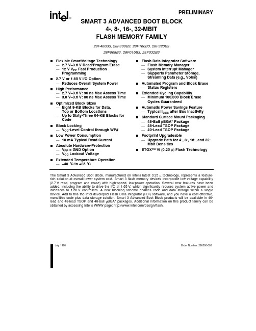
The Smart 3 Advanced Boot Block, manufactured on Intel’s latest 0.25 µ technology, represents a featurerich solution at overall lower system cost. Smart 3 flash memory devices incorporate low voltage capability (2.7 V read, program and erase) with high-speed, low-power operation. Several new features have been added, including the ability to drive the I/O at 1.65 V, which significantly reduces system active power and interfaces to 1.65 V controllers. A new blocking scheme enables code and data storage within a single device. Add to this the Intel-developed Flash Data Integrator (FDI) software, and you have a cost-effective, monolithic code plus data storage solution. Smart 3 Advanced Boot Block products will be available in 40lead and 48-lead TSOP and 48-ball µBGA* packages. Additional information on this product family can be obtained by accessing Intel’s WWW page: /design/flash.
RB-XX3.3D中文资料
3rd angle projection
19.60 6.00
Dual Output RB-0505D RECOM **** RB-0505D RECOM ****
Single Output RB-0505S RECOM ****
Pin Connections Pin # 1 2 Single +Vin –Vin NC –Vout +Vout Dual +Vin –Vin –Vout Com +Vout
元器件交易网
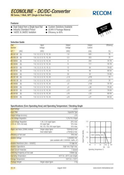
ECONOLINE - DC/DC-Converter
RB Series, 1 Watt, SIP7 (Single & Dual Output) Features
● ● ●
Dual Output from a Single Input Rail Industry Standard Pinout 1kVDC & 2kVDC Isolation
10.20
0.51 typ.
4.10
0.51 typ.
1 2
4 5 6
1 2
4 5 6
4 5 6
NC = No Connection
1.27 2.0
0.25
1 2 4 5 6
12.70
Recommended Footprint Details
1.00 ø+0.ቤተ መጻሕፍቲ ባይዱ5/–0 2.54
2.54
XX.X ± 0.5 mm XX.XX ± 0.25 mm
Output Power (Watts) 2.0 1.5 1.0 Safe Operating Area 0.5 0 -40 0 50 100 125 150 85 Operating Temperature ˚C
CZRB3013中文资料
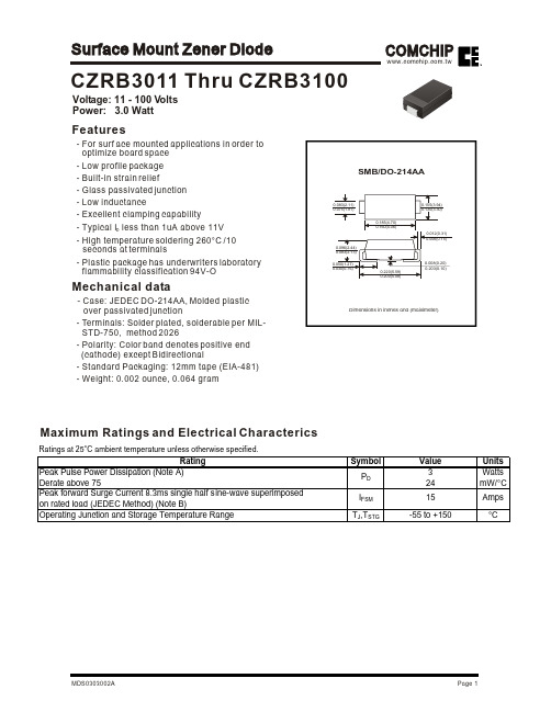
Voltage: 11 - 100 V olts Power: 3.0 WattCZRB3011Thru CZRB3100Features- For surf ace mounted applications in order to optimize board space - Low profile package - Built-in strain relief- Glass passivated junction - Low inductance- Excellent clamping capability- Typical I less than 1uA above 11V D - High temperature soldering 260°C /10seconds at terminals- Plastic package has underwriters laboratory flammability classification 94V-OMechanical data- Case: JEDEC DO-214AA,Molded plastic over passivated junction- Terminals: Solder plated, solderable per MIL-STD-750, method 2026- Polarity: Color band denotes positive end (cathode) except Bidirectional-Standard Packaging: 12mm tape (EIA-481) -Weight: 0.002 ounce, 0.064 gramMaximum Ratings and Electrical CharactericsRatings at 25°C ambient temperature unless otherwise specified.I ZKV R(Volts)(mA)(Ohms)(Ohms)(mA)(uA)(Volts)MadcIr - mACZRB3011116847000.2518.4225 1.82CZRB30121263 4.57000.2519.1246 1.66CZRB30131358 4.57000.250.59.9208 1.54CZRB3014145357000.250.510.6193 1.43CZRB30151550 5.57000.250.511.4180 1.33CZRB30161647 5.57000.250.512.2169 1.25CZRB3017174467500.250.513150 1.18CZRB3018184267500.250.513.7159 1.11CZRB3019194077500.250.514.4142 1.05CZRB3020203777500.250.515.2135 1.00CZRB3022223487500.250.516.71230.91CZRB3024243197500.250.518.21120.83CZRB30272728107500.250.520.61000.74CZRB30282827127500.250.521960.71CZRB303030251610000.250.522.5900.67CZRB303333232010000.250.525.1820.61CZRB303636212210000.250.527.4750.56CZRB303939192810000.250.529.7690.51CZRB304343173315000.250.532.7630.45CZRB304747163815000.250.535.6570.42CZRB305151154515000.250.538.8530.39CZRB305656135020000.250.542.6480.36CZRB306262125520000.250.547.1440.32CZRB306868117020000.250.551.7400.29CZRB307575108520000.250.556360.27CZRB3082829.19530000.250.562.2330.24CZRB3091918.211530000.250.569.2300.22CZRB31001007.516030000.250.576270.20NOTE:MaximumZenerCurrent I ZM1. Tolerance and Type Number Designation. The type numbers listed have a standard tolerance on the nominal zener voltage of ±5%.2. ZENER VOLTAGE (Vz) MEASUREMENT - guarantees the zener voltage when measured at 40 ms +- 10ms from the diode body, and an ambient temperature of 25 °C (+8°C , -2°C ).3.ZENER IMPEDANCE (Zz) DERIVATION - The zener impedance is derived from the 60 cycle ac voltage, which results when an ac current having an rms falue equal to 10% of the dc zener current (I ZT or I ZK ) is superimposed on I ZT or I ZK .4. SURGE CURRENT (Ir) NON-REPETITIVE - The rating listed in the electrical characteristics table is maximum peak, non-repetitive, reverse surge current of 1/2 square wave or equivalent sine wave pulse of 1/120 second duration superimposed on the test current, I ZT , per JEDEC standards, however, actual device capability is as described in Figure 3.ELECTRICAL CHARACTERISTICS(T A =25°C unless otherwise noted) (V F =1.2Volts Max, I F =500mA for all types.)Device (Note 1.)Nominal ZenerVoltage V Z @ I ZT(Note 2.)Test current I ZTMaximum Zener Impedance(Note 3.)Leakage Current SurgeCurrent@T A =25°C(Note 4.)Z ZT @ I ZT Z ZK @ I ZKI RRating and Characteristic Curves (CZRB3011Thru CZRB3100)Fig.2-TYPICAL THERMAL RESPONSE L,P.W.PULSE WIDTH (ms)0.10.050.030.020.010.0050.0030.0020.0010.00050.00030.00020.0001NOMINAL VZ (VOLTS)Fig.3-MAXIMUM SURGE POWERFig.4-TYPICAL REVERSE LEAKAGEVZ,ZENER VOLTAGE @IZT (VOLTS)VZ,ZENER VOLTAGE @IZT (VOLTS)Fig.5-UNITS TO 12VOLTS Fig.6-UNITS 10TO 100VOLTSRating and Characteristic Curves (CZRB3011 Thru CZRB3100)VZ,ZENER VOLTAGE (VOLTS)VZ,ZENER VOLTAGE (VOLTS)L,LEAD LENGTH TO HEAT SINK(INCH)TYPICAL THERMAL RESISTANCEAPPLICATION NOTE:Since the actual voltage available from a given zener diode is temperature dependent, it is necessary to determine junction temperature under any set of operating conditions in order to calculate its value. The following procedure is recommended:Lead Temperature, T L, should be determined from:T L = șLA P D + T AșLA is the lead-to-ambient thermal resistance (°C/W)and PD is the power dissipation. The value forșLA willvary and depends on the device mounting method.șLA is generally 30-40 °C/W for the various chips andtie points in common use and for printed circuit boardwiring.The temperature of the lead can also be measured using a thermocouple placed on the lead as close as possible to the tie point. The thermal mass connected to the tie point is normally large enough so that it will not significantly respond to heat surges generated in the diode as a result of pulsed operation once steady-state conditions are achieved. Using the measured value of T L, the junction temperature may be determined by:T J = T L + ¨T JL ¨T JL is the increase in junction temperature above the lead temperature and may be found from Figure 2 for a train of power pulses or from Figure 10 for dc power.¨T JL = șLA P DFor worst-case design, using expected limits of Iz, limits of PD and the extremes of TJ (¨T JL ) may be estimated. Changes in voltage, Vz, can then be found from:¨V = șVZ¨T JșVZ , the zener voltage temperature coefficient, isfound from Figures 5 and 6.Under high power-pulse operation, the zener voltagewill vary with time and may also be affected significantly be the zener resistance. For best regulation, keep current excursions as low as possible.Data of Figure 2 should not be used to compute surge capability. Surge limitations are given in Figure 3. They are lower than would be expected by considering only junction temperature, as current crowding effects cause temperatures to be extremely high in small spots resulting in device degradation should the limits of Figure 3 beexceeded.COMCHIPSurface Mount Zener Diode。
FDC6331L中文资料
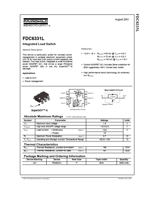
Figure 2. Conduction Voltage Drop Variation with Load Current.
IL = -1A V O N / O F F = -1.5V -8V PW = 300us, D < 2%
0.125
0.1
0.075 T J = 125OC 0.05 TJ = 25OC 0.025
FDC6331L Leabharlann ev C(W)元器件交易网
FDC6331L
0.4 0.35 0.3 -V DROP, (V) 0.25 0.2 0.15 0.1 0.05 0 0 1 2 3 -I L, (A) 4 5 6 TJ = 25 OC V IN = -1.8V V ON/OFF = -1.5V -8V PW = 300us, D < 2%
(Note 2)
–0.6 –1.2
A V
Notes: 1. R θJ A is the sum of the junction-to-case and case-to-ambient thermal resistance where the case thermal reference is defined as the solder mounting surface of the drain pins. R θJC is guar anteed by design while R θJ A is determined by the user’s board design. 2. Pulse Test: Pulse Width < 300µs, Duty Cycle < 2.0%.
Features
• –2.8 A, –8 V. RDS(ON) = 55 mΩ @ V GS = –4.5 V RDS(ON) = 70 mΩ @ V GS = –2.5 V RDS(ON) = 100 mΩ @ V GS = –1.8 V • Control MOSFET (Q1) includes Zener protection for ESD ruggedness (>6KV Human body model) • High performance trench technology for extremely low RDS(ON)
RM-3.31.8DP中文资料
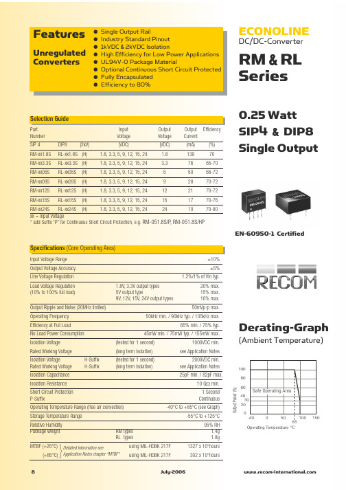
0512
3.312
15.000 10.000 5.000 0.000 -5.000 -10.000
0515
1212
1215
0% 20% 40% 60% Total Output current (%)
80%
100%
0% 20% 40% 60% Total Output current (%)
80%
100%
Output Power (%)
100 80 60 40 30 20 0
Derating-Graph
(Ambient Temperature)
1 Second Continuous -40°C to +85°C (see Graph) -55°C to +125°C 95% RH 1.4g 1.8g 1327 x 103 hours 302 x 103 hours
Deviation / Load
25.000 20.000 25.000 20.000
Deviation / Load
Deviation from Nominal (%)
15.000 10.000 5.000 0.000 -5.000 -10.000
Deviation from Nominal (%)
EN-60950-1 Certified
Specifications (Core Operating Area)
Input Voltage Range Output Voltage Accuracy Line Voltage Regulation Load Voltage Regulation (10% to 100% full load) Output Ripple and Noise (20MHz limited) Operating Frequency Efficiency at Full Load No Load Power Consumption Isolation Voltage Rated Working Voltage Isolation Voltage Rated Working Voltage Isolation Capacitance Isolation Resistance Short Circuit Protection P-Suffix Operating Temperature Range (free air convection) Storage Temperature Range Relative Humidity Package Weight MTBF (+25°C) (+85°C) 8 RM types RL types
三莘三相半波保护过流电压开关数据表3RB2143-4EW1说明书
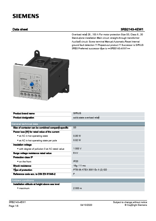
3RB2143-4EW1 Page 4/5
04/10/2020
Subject to change without notice © Copyright Siemens
67 86
35 51
Marine / Shipping
other
Miscellaneous
Confirmation
Further information Information- and Downloadcenter (Catalogs, Brochures,…)
https:///ic10
Data sheet
3RB2143-4EW1
Overload relay 25...100 A For motor protection Size S3, Class 5...30 Stand-alone installation Main circuit: straight-through transformer Auxiliary circuit: Screw terminal Manual-Automatic-Reset Internal ground fault detection !!! Phased-out product !!! Successor is SIRIUS 3RB3 Preferred successor type is >>3RB3143-4XW1<<
Relative humidity during operation
-25 ... +60 °C -40 ... +80 °C -40 ... +80 °C 100 %
Main circuit Number of poles for main current circuit Adjustable pick-up value current of the currentdependent overload release Operating voltage
RB-3SS-C Rinnai Built-In Hob 用户手册说明书
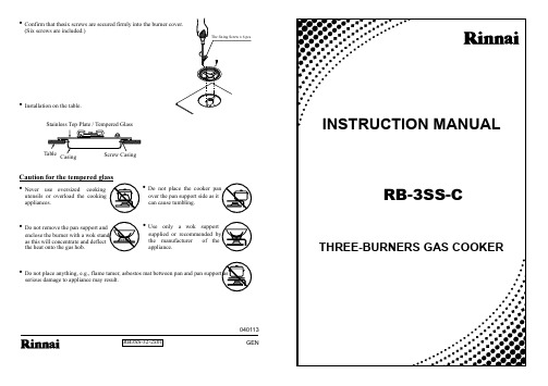
•Confirm that the screws are secured firmly into the burner cover.(Six screws are included.)six RB3SS-32-2x01040113•Installation on the table.TableCasingScrew CasingStainless Top Plate / Tempered GlassThe fixing Screw x 6 pcsTHREE-BURNERS GAS COOKERINSTRUCTION MANUALRB-3SS-CCaution for the tempered glass•Neveruse oversized cookingutensils or overload the cooking appliances.•Do not remove the pan support andenclose the burner with a wok stand as this will concentrate and deflect the heat onto the gas hob.•Do not place anything, e.g., flame tamer, asbestos mat between pan and pan support asserious damage to appliance may result.•Do not place the cooker panover the pan support side as it can cause tumbling.•Useonly a wok support supplied or recommended by the manufacturer of the appliance.GENFig. 1In order to obtain the best results and to maintain your Rinnai Built-In Hob in the best condition, please read the instruction carefully.Components and Features Trouble Shooting Manual for Rinnai RB-3SS Built-in HobMaintenance•Wipe the tempered glass with a soft damp cloth and mild detergent.• Wash the Pan Support and Burner Covers in warm water and detergent.Components and parts namesFAULTCAUSE1. No Ignition Spark electrode is wet, especially in high humidity season Dry the electrode with clean tissue or dry cloth.2. Flame cannot be heldIncorrect turning of gas control knob.Push and turn the gas control knob anti-clockwise until a ‘click’ sound is heard. Hold for a few seconds until flame is ignited.4. Yellow flameAccumulated grease and dirt on the burner head.Wash the burner head in warm water with detergent. Leave it to dry; then place it back in the correct position.5.Unstable flameIncorrect location of the burner head.Refit the burner head into the burnerbody3.No main flame3.1 Gas Regulator has beenturned off Open gas regulator completely3.2 Burner cap is blocked byaluminum foil.Remove aluminum foil.REMEDYGas Inlet(For Singapore model only)T .G .L .P .G.Attention: when installing the casing••Confirm that six screws are firmly secured into the casing.Adjust screw position as bench cut out size.Casing ElectrodeKnob Safety SensorStainless Top PlateBurner Cap Pan SupportH Burner Head H Burner BodyH Burner CoverTempered GlassPan SupportM Burner Head M Burner Body M Burner CoverInstallation1. Pan SupportFit Pan Support into Top Plate. (Fig.2)2. Burner Head and Burner CapFit burner head into burner cap onto the burner body correctly, without any gap. (see Fig.3)3. Installation of Gas HoseOperating Instruction Ignition• A specific rubber hose for built-in hob must be used .•The rubber hose must not be bent during installation and must be of an appropriate length (less than 2 m).•During installation, make sure that the rubber hose does not come into contact with the body of the built-in hob pass through the bottom part of the built-in hob to prevent melting of the hose.• Place the securing ring over the rubber hose and connect the rubber hose to the coupler below the rear side of the built-in hob till the marked red line. Then secure the rubber hose in position with the securing ring (For LP Gas).• The connection must be performed by a qualified person according to the relevant standards(For LP Gas). For Town Gas / Natural Gas, the task must be executed by a qualified licensed technician.•Do not use any other gas except for the ones indicated on the specification label of the built-in hob.•LPG is the abbreviation for Liquefied Petroleum Gas, while TG is Town Gas supplied through pipelines.•For liquefied petroleum gas, please use conventional household low pressure regulators. The standard pressure for LPG gas is 280 mm H O that for TG gas is 100 mm H O.• Do not increase the gas pressure• Never turn the LPG gas container upside down or subject to high temperatures or direct sunlight.•Conversion of built-in hob from one gas type to another must be performed by a qualifiedtechnician as major components need to be replaced.221. Depress the control knob to about 2 mm and turn to the left (counter clock-wise) to the “ON” position.2.When the control knob is being turned for ignition, sparks are generated to ignite the burning device, accompanied by clicking sound.4. Precaution gasG A PG AP (Fig.3)Burner CapBurner BodyBurner HeadSpark ElectrodeSafety SensorXFig. 2•Install the built-in hob in well ventilated area and keep away from any combustible or inflammable object i.e. paper, oil, etc.•If the built-in hob is to be installed near any combustible surrounding i.e. wooden walls, wooden shelves, etc, there should be a distance of more than 15cm (6 in) away from the surrounding combustible. If the surrounding materials are fireproof, the clearance is not required.•Place the built-in hob on a stable and level surface• This built in hob is to be used for cooking purposes only. Do not use it to dry towel, clothes or any other materials over it.• Make sure that the following parts are fitted properly before use.Cut-Out Hole SizeFeaturesSpecification1. The tempered glass and stainless top plate is beautiful and stylish.2.The enamel pan supports are durable and will not deform, making it stable for your cooking vessels.3. The automatic continuous ignition device will ensure a 100% ignition rate.4.Each built-in hob is equipped with a safety valve which will cut off the gas supply automatically if the flame is accidentally extinguished (For SV model only).3. Do not release the control knob for 2-5 seconds after the sparks have ignited the burner to activate the safety device. Otherwise, the ignition will fail.4. In the event of the burner flames being accidentally extinguished , turn off the burner control and do not attempt to re-ignite the burner for at least 1 min.The device shall not be operated for more than 15 seconds. If the burner has not lit up after 15 seconds, stop operating the built-in hob and open the compartment door and/or wait for at least 1 minute before attempting to ignite the burner again.5. The flame can be controlled between “MAX” “MED”and “MIN” position, please adjust the flame slowly.6. For H burner, flame can be controlled with four combination, as shown by Fig. 4:How to Handle Safety Device and Change Battery7. Do not clean the top of the sensor with a hard brush, as it may damage the sensor.1. After use, turn the control knob right to the “OFF” position, and the flame will be extinguished.2. Make sure that the control knob is fully turned to the “OFF”position, less there would be a danger of gas leakage.3. After extinguishing the flame, do not touch the conductive parts of the hobs as they remain at very high temperatures.4. There may be a slight hissing sound after the flames is extinguished.5. If the built-in-hob is not in use, turn off the main gas supply to avoid gas leakage or unnecessary accidents.Flame ExtinguishingFig. 5Gas InletFront Side”C” Size Battery(1.5Vx1)1. If the flame is extinguished during operation, the Flame Failure Safety Device will automatically cut off the gas within second.If you notice that the flame has been extinguished, please turn the knob to “OFF” position.2. The Safety Sensor is delicate, please do not use stiff brushes or rough cleaning pads when cleaning.•Aeration is preset at factory during assembly; please do not attempt to adjust it.•Battery Box is located at bottom of right front (Size C, 1.5V x 1) (Fig.5).Open the cabinet door, and change the battery.out side flame inside flame : Max : Max: Off out side flame inside flame : Max: Off out side flame inside flame : Minout side flame inside flame : Medium : MediumFig. 4R0 ~ R110725~84065435~480550Gas Type Gas Consumption per hour Respective gas consumption (kW)Main RHS / LHS (kW) Gas Connecting Tube3.602.703.901.35L.P.G (30 mbar)Nozzle/injector size 4.200.95Ø9.5 mm gas specific rubber hose ½ In Thread (male)Ø9.5 mm gas specific rubber hoseSimmer 1.001.350.800.650.500.36T.G. (8 mbar)Nozzle/injector size N.G. (25 mbar)Nozzle/injector sizeMain Center 2.101.902.300.732.200.73Product Net WeightModelAutomatic Continuous IgnitionsOverall Dimension Cut out sizeBuilt-in Hob RB-3SS 17 Kg 21 Kg435~480 mm x 725~840 mmR0 mm ~ R110 mm“C” Size Battery (1.5V x 1)RB-3SS (S)RB-3SS (GB)RB-3SS (S)RB-3SS (GB)Diameters of pan which may be used on hob* Use only flat bottom pan except for wok burnerBurners 280 mmMax MainMin 120 mm870 mm x 510 mm x 131 mm 880 mm x 520 mm x 131 mm。
ROHM RB531S-30 超导腐蚀二极管说明书
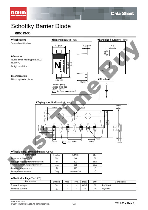
Schottky Barrier DiodeRB531S-30●ApplicationsGeneral rectification●Features1)Ultra small mold type.(EMD2)2)Low V F3)High reliability●ConstructionSilicon epitaxial planer●Absolute maximum ratings (Ta=25︒C)SymbolUnit V RV Io mA I FSM mATj ︒C Tstg︒C●Electical voltage (Ta=25︒C)Symbol Min.Typ.Max.Unit ConditionsForward voltage V F--0.35V I F =10mA I R--10μAV R =10VJunction temperature 125Storage temperature-40to+125Parameter Reverse currentParameter Limits Reverse voltage(DC)30Average rectified forward current100Forward current surge peak(60Hz/1cyc)500L aElectrical characteristics curves0.0010.010.1110100100001002003004005006000.010.111010010001000001020301101005101520101112131415161718192051015202530250260270280290300510152005101101005101101000.020.040.060.080.101020300.020.040.060.080.10.10.21010010000.0010.010.11101001000FORWARD VOLTAGE : V F (mV)V F -I F CHARACTERISTICS F O R W A R D C U R R E N T : I F (m A )R E V E R S E C U R R E N T : I R (μA )REVERSE VOLTAGE : V R (V)V R -I R CHARACTERISTICSC A P A C I T A N C E B E T W E E N T E R M I N A L S : C t (p F )REVERSE VOLTAGE : V R (V)V R -Ct CHARACTERISTICSV F DISPERSION MAPF O R W A R D V O L T AG E : V F (m V )R E V E R S E C U R R E N T : I R (μA )I R DISPERSION MAPC A P A C I T A N C E B E T W E E N T E R M I N A L S :C t (p F )Ct DISPERSION MAPI FSM DISRESION MAPP E A K S U R G E F O R W A R D C U R R E N T : I F S M (A )P E A K S U R G E F O R W A R D C U R R E N T : I F S M (A )NUMBER OF CYCLESI FSM -CYCLE CHARACTERISTICSP E A K S U R G E F O R W A R D C U R R E N T : I F S M (A )TIME : t(ms)I FSM -t CHARACTERISTICSTIME : t(s)Rth-t CHARACTERISTICST R A N S I E N T T H A E R M A L I M P E D A N C E : R t h (︒C /W )F O R W A R D P O W E R D I S S I P A T I O N : P f (W )AVERAGE RECTIFIED FORWARD CURRENT : Io(A)Io-Pf CHARACTERISTICSR E V E R S E P O W E R D I S S I P A T I O N : P R (W )REVERSE VOLTAGE : V R (V)V R -P R CHARACTERISTICS00.10.20.325507510012500.10.20.3255075100125AMBIENT TEMPERATURE : Ta(︒C)Derating Curve"(Io-Ta)A V E R A G E R E C T I F I E D F O R W A R D C U R R E N T : I o (A )A V E R A G E R E C T I F I E D F O R W A R D C U R R E N T : I o (A )CASE TEMPARATURE : Tc(︒C)Derating Curve"(Io-Tc)L a st Ti me Bu yNoticePrecaution on using ROHM Products1. Our Products are designed and manufactured for application in ordinary electronic equipments (such as AV equipment,OA equipment, telecommunication equipment, home electronic appliances, amusement equipment, etc.). If youintend to use our Products in devices requiring extremely high reliability (such as medical equipment(Note 1), transport equipment, traffic equipment, aircraft/spacecraft, nuclear power controllers, fuel controllers, car equipment including car accessories, safety devices, etc.) and whose malfunction or failure may cause loss of human life, bodily injury or serious damage to property (“Specific Applications”), please consult with the ROHM sales representative in advance. Unless otherwise agreed in writing by ROHM in advance, ROHM shall not be in any way responsible or liable for any damages, expenses or losses incurred by you or third parties arising from the use of any ROHM’s Products for Specific Applications.(Note1) Medical Equipment Classification of the Specific ApplicationsJAPAN USA EU CHINA CLASS Ⅲ CLASS Ⅲ CLASS ⅡbCLASS ⅢCLASS Ⅳ CLASS Ⅲ2. ROHM designs and manufactures its Products subject to strict quality control system. However, semiconductorproducts can fail or malfunction at a certain rate. Please be sure to implement, at your own responsibilities, adequate safety measures including but not limited to fail-safe design against the physical injury, damage to any property, which a failure or malfunction of our Products may cause. The following are examples of safety measures:[a] Installation of protection circuits or other protective devices to improve system safety [b] Installation of redundant circuits to reduce the impact of single or multiple circuit failure3. Our Products are designed and manufactured for use under standard conditions and not under any special orextraordinary environments or conditions, as exemplified below. Accordingly, ROHM shall not be in any way responsible or liable for any damages, expenses or losses arising from the use of any ROHM’s Products under any special or extraordinary environments or conditions. If you intend to use our Products under any special or extraordinary environments or conditions (as exemplified below), your independent verification and confirmation of product performance, reliability, etc, prior to use, must be necessary:[a] Use of our Products in any types of liquid, including water, oils, chemicals, and organic solvents [b] Use of our Products outdoors or in places where the Products are exposed to direct sunlight or dust[c] Use of our Products in places where the Products are exposed to sea wind or corrosive gases, including Cl 2, H 2S, NH 3, SO 2, and NO 2[d] Use of our Products in places where the Products are exposed to static electricity or electromagnetic waves [e] Use of our Products in proximity to heat-producing components, plastic cords, or other flammable items [f] Sealing or coating our Products with resin or other coating materials[g] Use of our Products without cleaning residue of flux (even if you use no-clean type fluxes, cleaning residue of flux is recommended); or Washing our Products by using water or water-soluble cleaning agents for cleaning residue after soldering[h] Use of the Products in places subject to dew condensation4. The Products are not subject to radiation-proof design.5. Please verify and confirm characteristics of the final or mounted products in using the Products.6. In particular, if a transient load (a large amount of load applied in a short period of time, such as pulse. is applied,confirmation of performance characteristics after on-board mounting is strongly recommended. Avoid applying power exceeding normal rated power; exceeding the power rating under steady-state loading condition may negatively affect product performance and reliability.7. De-rate Power Dissipation (Pd) depending on Ambient temperature (Ta). When used in sealed area, confirm the actualambient temperature.8. Confirm that operation temperature is within the specified range described in the product specification.9. ROHM shall not be in any way responsible or liable for failure induced under deviant condition from what is defined inthis document.Precaution for Mounting / Circuit board design1. When a highly active halogenous (chlorine, bromine, etc.) flux is used, the residue of flux may negatively affect productperformance and reliability.2. In principle, the reflow soldering method must be used on a surface-mount products, the flow soldering method mustbe used on a through hole mount products. If the flow soldering method is preferred on a surface-mount products, please consult with the ROHM representative in advance. For details, please refer to ROHM Mounting specificationL a st Ti me Bu yPrecautions Regarding Application Examples and External Circuits1. If change is made to the constant of an external circuit, please allow a sufficient margin considering variations of thecharacteristics of the Products and external components, including transient characteristics, as well as static characteristics.2. You agree that application notes, reference designs, and associated data and information contained in this documentare presented only as guidance for Products use. Therefore, in case you use such information, you are solely responsible for it and you must exercise your own independent verification and judgment in the use of such information contained in this document. ROHM shall not be in any way responsible or liable for any damages, expenses or losses incurred by you or third parties arising from the use of such information.Precaution for ElectrostaticThis Product is electrostatic sensitive product, which may be damaged due to electrostatic discharge. Please take propercaution in your manufacturing process and storage so that voltage exceeding the Products maximum rating will not be applied to Products. Please take special care under dry condition (e.g. Grounding of human body / equipment / solder iron, isolation from charged objects, setting of Ionizer, friction prevention and temperature / humidity control).Precaution for Storage / Transportation1. Product performance and soldered connections may deteriorate if the Products are stored in the places where:[a] the Products are exposed to sea winds or corrosive gases, including Cl2, H2S, NH3, SO2, and NO2 [b] the temperature or humidity exceeds those recommended by ROHM [c] the Products are exposed to direct sunshine or condensation [d] the Products are exposed to high Electrostatic2. Even under ROHM recommended storage condition, solderability of products out of recommended storage time periodmay be degraded. It is strongly recommended to confirm solderability before using Products of which storage time is exceeding the recommended storage time period.3. Store / transport cartons in the correct direction, which is indicated on a carton with a symbol. Otherwise bent leadsmay occur due to excessive stress applied when dropping of a carton.4. Use Products within the specified time after opening a humidity barrier bag. Baking is required before using Products ofwhich storage time is exceeding the recommended storage time period.Precaution for Product Label QR code printed on ROHM Products label is for ROHM’s internal use only.Precaution for DispositionWhen disposing Products please dispose them properly using an authorized industry waste company.Precaution for Foreign Exchange and Foreign Trade actSince concerned goods might be fallen under listed items of export control prescribed by Foreign exchange and Foreign trade act, please consult with ROHM in case of export.Precaution Regarding Intellectual Property Rights1. All information and data including but not limited to application example contained in this document is for referenceonly. ROHM does not warrant that foregoing information or data will not infringe any intellectual property rights or any other rights of any third party regarding such information or data. 2. ROHM shall not have any obligations where the claims, actions or demands arising from the combination of theProducts with other articles such as components, circuits, systems or external equipment (including software).3. No license, expressly or implied, is granted hereby under any intellectual property rights or other rights of ROHM or anythird parties with respect to the Products or the information contained in this document. Provided, however, that ROHM will not assert its intellectual property rights or other rights against you or your customers to the extent necessary to manufacture or sell products containing the Products, subject to the terms and conditions herein. Other Precaution1. This document may not be reprinted or reproduced, in whole or in part, without prior written consent of ROHM.2. The Products may not be disassembled, converted, modified, reproduced or otherwise changed without prior writtenconsent of ROHM. 3. In no event shall you use in any way whatsoever the Products and the related technical information contained in theProducts or this document for any military purposes, including but not limited to, the development of mass-destruction weapons. 4. The proper names of companies or products described in this document are trademarks or registered trademarks ofROHM, its affiliated companies or third parties.L a st Ti me Bu yGeneral Precaution1. Before you use our Pro ducts, you are requested to care fully read this document and fully understand its contents.ROHM shall n ot be in an y way responsible or liabl e for fa ilure, malfunction or acci dent arising from the use of a ny ROHM’s Products against warning, caution or note contained in this document.2. All information contained in this docume nt is current as of the issuing date and subj ect to change without any priornotice. Before purchasing or using ROHM’s Products, please confirm the la test information with a ROHM sale s representative.3. The information contained in this doc ument is provi ded on an “as is” basis and ROHM does not warrant that allinformation contained in this document is accurate an d/or error-free. ROHM shall not be in an y way responsible or liable for any damages, expenses or losses incurred by you or third parties resulting from inaccuracy or errors of or concerning such information.L a st Ti me Bu y。
西门子型号3RB3.3-..的产品说明书
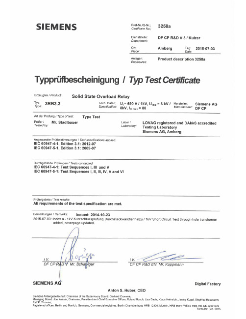
3RB3.3.-..Werner-von-Siemens-Str. 48, 92220 Amberg14013ENI01, 14013ENI02, 14013ENI03, 14-E005865-BM-A01Overview series 3RB3.3.-..036-1- Solid-state overload relay0- self powered1- self powered with earth ground indication3- Size S23- manual or automatic reset or remote reset6- manual or automatic reset1- class 102- class 204- class 5, 10, 20 or 30, adjustable- 6 - 25 A- 12,5 - 50 A- 20 - 80 A- main circuit - screw terminals / auxiliary circuit - screw terminals- main circuit - screw terminals / auxiliary circuit - spring terminals- main circuit straight through current transformer / auxiliary circuit - screw terminals- main circuit straight through current transformer / auxiliary circuit - spring terminals0- direct mounting1- separate mounting3RU2936-3AA013RB3984-0- kind of equipment ..................................................................- number of poles 3- kind of current (a.c. or d.c.) ...................................................- interrupting medium N/A- method of operation N/A- method of control manual / automatic- rated frequency 50/60 Hz- rated duties ............................................................................ N/A- Utilization category N/A- rated operational voltage Ue (V) ...........................................Relays with straight-through transformers) - rated insulation voltage Ui (V) ...............................................Relays with straight-through transformers) - rated impulse withstand voltage Uimp(kV) ...........................Relays with straight-through transformers) - conventional free air thermal current Ith (A)- conventional enclosed thermal current Ithe (A) .................... N/A- rated operational current Ie (A) or rated operational powers- rated uninterrupted current Iu (A) N/ARated conditional short-circuit current- rated prospective short-circuit current "r" (kA) ...................... 759V / 3/5kA1000V /3/5kA Relays with straight-through- rated conditional short-circuit current Iq (kA) ........................ 759V / 100kA1000V / 25kA Relays with straight-through-type of co-ordination ...............................................................-Pole impedance of a contactor (Z) -- kind of current ........................................................................- rated frequency if a.c. -- rated control circuit voltage Uc (nature: a.c. / d.c.) ..............- rated control supply voltage Us (nature: a.c. / d.c.) ............. -Werner-von-Siemens-Str. 48, 92220 Amberg3RB3.3.-..IEC 60947-4-1 Edition 3.1, (2012-07)IEC 60947-5-1 Edition 3.1, (2009-07)14013ENI01, 14013ENI02, 14013ENI03, 14-E005865-BM-A01 3RB3133-4UB0 +3RT2038-1AP00=50A / 10A / 5A3RB3133-4WB0 +3RT2038-1AP00=80A / 10A / 5A3RB3133-4WD0 +3RT2038-1AP00=80A / 10A / 5A3RB3133-4QB0 +3RT2036-1AP00=25A / 10A / 5A3RB3133-4WB0 +3RT2038-1AP003NA3 244-6 / 250A3RB3133-4WD0 +3RT2038-1AP003NA3 244-6 / 250A3RB3133-4QB0 +3RU2936-3AA01 G/1403243NA3 236-6 / 160A3RB3133-4UB0 +3RU2936-3AA01 G/1403243NA3 240-6 / 200A3RB3133-4WD0 +3RU2936-3AA01 G/1403243NA3 244-6 / 250A3RB3133-4WB0 +3RT2038-1AP00 G/1403243NA3 236-6 / 160A3RB3133-4UB0 +3RU2936-3AA01 G/1403243NA3 240-6 / 200A3RB3036-1WB0 +3RU2936-3AA01 G/1403243NA3 244-6 / 250A3RB3036-1WD0 +3RT2038-1AP00 G/1403243NA3 236-6 / 160A3RB3133-4QB0 +3RU2936-3AA01 G/1403243NA3 236-6 / 160A3RB3133-4WB0 LO/1311273RB3133-4WB0 LO/1311273RB3133-4WB03RB3133-4WD0For mechanical and electrical properties of the auxiliary- and control-circuit terminals see Test3RB3133-4UB0 +3RT2038-1AP00=50A / 10A / 5A3RB3133-4WB0 +3RT2038-1AP00=80A / 10A / 5A3RB3133-4WD0 +3RT2038-1AP00=80A / 10A / 5A3RB3133-4QB0 +3RT2036-1AP00=25A / 10A / 5AFor mechanical and electrical properties of auxiliary- and control-circuit terminals see Test ReportSeq. II/III3RB3036-2UW1 DC-13: NC (95-96) 24V / 2A3RB3036-2UW1 DC-13: NO (97-98) 24V / 2A3RB3036-2UW1 AC-15: NC (95-96) 250V / 3A3RB3036-1QW1 AC-15: NO (97-98) 250V / 3A3RB3133-4WB03RB3133-4WD03RB3133-4WW1fuse: SIBA / 160A/1000V, gB 3RB3133-4QW1fuse: SIBA / 160A/1000V, gB 3RB3133-4UW1fuse: SIBA 160A/1000V, gBWerner-von-Siemens-Str. 48, 92220 AmbergAccredited-No.: D-PL-11055-04-0021Guenther-Scharowsky-Str.91058Accredited-No.: D-PL-11055-13-01。
3B32资料
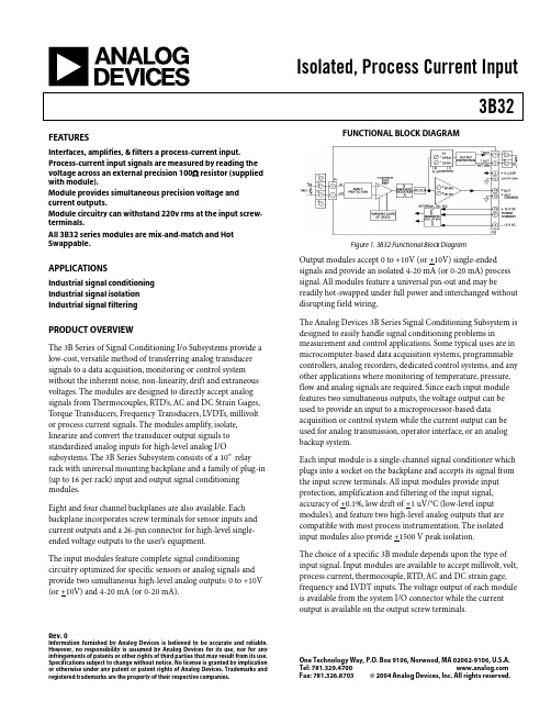
Isolated, Process Current Input3B32Rev. 0Information furnished by Analog Devices is believed to be accurate and reliable. However, no responsibility is assumed by Analog Devices for its use, nor for any infringements of patents or other rights of third parties that may result from its use. Specifications subject to change without notice. No license is granted by implication or otherwise under any patent or patent rights of Analog Devices. Trademarks and registered trademarks are the property of their respective companies.One Technology Way, P.O. Box 9106, Norwood, MA 02062-9106, U.S.A.Tel: 781.329.4700 Fax: 781.326.8703© 2004 Analog Devices, Inc. All rights reserved.FEATURESInterfaces, amplifies, & filters a process-current input.Process-current input signals are measured by reading the voltage across an external precision 100Ω resistor (supplied with module).Module provides simultaneous precision voltage and current outputs.Module circuitry can withstand 220v rms at the input screw-terminals.All 3B32 series modules are mix-and-match and Hot Swappable.APPLICATIONSIndustrial signal conditioning Industrial signal isolation Industrial signal filteringPRODUCT OVERVIEWThe 3B Series of Signal Conditioning I/o Subsystems provide a low-cost, versatile method of transferring analog transducer signals to a data acquisition, monitoring or control system without the inherent noise, non-linearity, drift and extraneous voltages. The modules are designed to directly accept analog signals from Thermocouples, RTD’s, AC and DC Strain Gages, Torque Transducers, Frequency Transducers, LVDTs, millivolt or process current signals. The modules amplify, isolate, linearize and convert the transducer output signals to standardized analog inputs for high-level analog I/Osubsystems. The 3B Series Subsystem consists of a 10” relay rack with universal mounting backplane and a family of plug-in (up to 16 per rack) input and output signal conditioning modules.Eight and four channel backplanes are also available. Eachbackplane incorporates screw terminals for sensor inputs and current outputs and a 26-pin connector for high-level single-ended voltage outputs to the user’s equipment.The input modules feature complete signal conditioning circuitry optimized for specific sensors or analog signals and provide two simultaneous high-level analog outputs: 0 to +10V (or +10V) and 4-20 mA (or 0-20 mA).FUNCTIONAL BLOCK DIAGRAMFigure 1. 3B32 Functional Block DiagramOutput modules accept 0 to +10V (or +10V) single-ended signals and provide an isolated 4-20 mA (or 0-20 mA) process signal. All modules feature a universal pin-out and may bereadily hot-swapped under full power and interchanged without disrupting field wiring.The Analog Devices 3B Series Signal Conditioning Subsystem is designed to easily handle signal conditioning problems inmeasurement and control applications. Some typical uses are in microcomputer-based data acquisition systems, programmable controllers, analog recorders, dedicated control systems, and any other applications where monitoring of temperature, pressure, flow and analog signals are required. Since each input module features two simultaneous outputs, the voltage output can be used to provide an input to a microprocessor-based data acquisition or control system while the current output can be used for analog transmission, operator interface, or an analog backup system.Each input module is a single-channel signal conditioner which plugs into a socket on the backplane and accepts its signal from the input screw terminals. All input modules provide input protection, amplification and filtering of the input signal, accuracy of +0.1%, low drift of +1 uV/o C (low-level input modules), and feature two high-level analog outputs that are compatible with most process instrumentation. The isolated input modules also provide +1500 V peak isolation.The choice of a specific 3B module depends upon the type of input signal. Input modules are available to accept millivolt, volt, process current, thermocouple, RTD, AC and DC strain gage, frequency and LVDT inputs. The voltage output of each module is available from the system I/O connector while the current output is available on the output screw terminals.3B32Rev. 0 | Page 2 of 8GENERAL DESCRIPTIONThe 3B32 is a single-channel signal conditioning module that interfaces, amplifies and filters a process-current input and provides simultaneous precision output voltage and current. Process-current input signals are measured by reading the voltage across an external precision 100Ω resistor (supplied). Model 3B32 performs complete signal conditioning, including isolating (+1500V peak input-to-output and power) andprotecting their computer side outputs from damage and loss of signal integrity, and shielding their inputs from damage from field-side over-voltage faults up to 220V rms. The current output withstands 130V rms without damage and interfaces user equipment through screw terminals located on the 3B Series backplane. Each plug-in, mix-and-match, hot-swappable module is easily field calibrated via front-panel zero and span adjustments for both voltage and current outputs.3B Series Custom-Ranging Program – Externally-programmable Model 3B32-00, enables the user to configure a special input range by using the optional plug-on AC1310ranging card, which houses user-supplied resistors to determine zero and span. To facilitate selecting resistors, a Windows program, 3B-CUSTOM, calculates resistor values based on the user-desired input/output ranges.A chopper-stabilized low-drift (+1uV/o C) input amplifier assures long-term stability. At the amplifier input, a stable, zero-scale input voltage is subtracted from the input signal to set the zero-scale value. Zero suppression can exceed 100% of the input range. This is ideal for expanded-scale applications requiring high-resolution measurement of a selected portion of an input signal. For user convenience, the zero and span can be factory configured to meet custom range needs (Model 3B32-CUSTOM) or can be externally programmed (Model 3B32-00) via user supplied resistors inserted in the optional AC1310 plug-on ranging card. Internal low-pass filtering with a 3Hz cutoff (-3dB) two-pole Butterworth filter enhances both 60 dB normal-mode and 160 dB common-mode rejection at 50/60 Hz, enabling accurate measurement of small signals in high electrical noise.Signal isolation is accomplished by transformer coupling with a proprietary modulation technique for linear, stable and reliable performance. The differential input circuit on the field side is fully floating, eliminating the need for any input grounding. A demodulator on the computer side of the signal transformer recovers the original signal, which is then filtered and buffered and drives a voltage-to-current converter to provide the current output...Figure 23B32Rev. 0 | Page 3 of 83B32 Models AvailableModel Input Range Output Ranges 13B32-00 Externally Programmable 2-10 V to ±10 V & 0 mA to 20 mA 3B32-01 4 mA to 20 mA 0 V to ±10 V & 4 mA to 20 mA 3B32-02 0 mA to20 mA0 V to ±10 V & 4 mA to 20 mA3B32-Custom* *1 Output current range may be user programmed to 4 mA to 20 mA using jumper supplied. 2Requires AC1310 ranging card.* Custom Input/Output ranges are available. Refer to configuration guide.3B32 Specifications(typical @ +25°C and ±15 V dc, and +24 V dc Power)Description Model 3B32Input RangesStandard Ranges 0 mA to 20 mA; 4 mA to 20 mACustom Ranges0 mA to 20 mA (refer to ordering section)Output RangesVoltage (R L > 2 K Ω) 0 V to +10 V; -10 V to +10 V Current (R L = 0 to 850Ω)1 4 mA to 20 mA or 0 mA to 20 mA Maximum Current Output Span0 mA to 31 mA Accuracy 2Initial @ +25°C±0.1% SpanNonlinearity ±0.01% SpanStability vs. TemperatureVoltage Output Zero ±25 ppm of Span/°C Span ±25 ppm of Reading/°CCurrent Output 3 Zero ±25 ppm of Span/°C Span±25 ppm of Reading/°C Zero and Span Adjustment Range 4±5% of SpanInput ResistorValue100 ΩAccuracy ±0.1% Stability vs. Temperature ±0.002%/°C Input Bias Current+3 nA3B32Rev. 0 | Page 4 of 8Input Resistance (Module)15 M Ω NoiseInput, 0.1 Hz to 10 Hz Bandwidth 0.2 µV rms Output, 100 kHz Bandwidth 50 µV rms Bandwidth, -3 dB3 Hz Output Rise Time, 10% to 90% Span200 msCommon-Mode Voltage (CMV)Input-to-Output, Continuous±1500 V peak, maximumTransient ANSI/IEEE C37.90.1-1989Common Mode Rejection (CMR)1 k Ω Source Imbalance, 50/60 Hz 160 dB Normal Mode Rejection, 50/60 Hz60 dBInput ProtectionContinuous220 V rms maximumTransient ANSI/IEEE C37.90.1-1989 Voltage Output Protection Continuous Short to Ground Current Output Protection130 V rms, continuousPower Supply Voltages 5±15 V dc Supplies Rated Operation ±(11.5 V dc to 16.5 V dc) Current ±10 mA Sensitivity±0.01% span/V+24 V dc Loop Supply Rated Operation +12 V dc to +30 V dc Current +27 mA @ l out = 20 mA Sensitivity±0.0002% span/VMechanical Dimensions3.15" x 3.395" x 0.775"(80.0 mm x 86.2 mm x 19.7 mm)EnvironmentalTemperature Range Rated Performance -25°C to +85°C Storage-55°C to +85°CRelative Humidity, 24 hours 0 to 95% @ +60°C non-condensing RFI Susceptibility±0.5% Span error @ 400 MHz, 5 Watt, 3 ft1For a 0 to 20 mA range, a typical minimum output current is 10 µA.2Includes the combined effects of repeatability, hysteresis, and nonlinearity. 3With respect to the voltage output. 4A wide range of custom zero suppression and span is available with the 3B32-00 model, using the AC1310 ranging card. 5+24 V dc loop power is required for driving the current output at loads up to 850Ω. If a current output load of 400Ω or less is applied, +15 V dc is sufficient for loop power. If only voltage output is used, loop power is not required. Specifications subject to change without notice.3B32Rev. 0 | Page 5 of 8PIN CONFIGURATIONS AND FUNCTIONAL DESCRIPTIONSFigure 3 3B32 Input Field ConnectionsTable 1. Pin Function Descriptions—Pin No.Description 1 n/c 2 HI 3 LO 4 n/cFigure 4 . Model 3B Series Module, with pin-out assignments.ESD CAUTIONESD (electrostatic discharge) sensitive device. Electrostatic charges as high as 4000 V readily accumulate on the human body and test equipment and can discharge without detection. Although this product features proprietary ESD protection circuitry, permanent damage may occur on devices subjected to high energy electrostatic discharges.Therefore, proper ESD precautions are recommended to avoid performance degradation or loss of functionality.3B32Rev. 0 | Page 6 of 8OUTLINE DIMENSIONSFigure 5. Outline Dimensions3B32 NOTESRev. 0 | Page 7 of 83B32Rev. 0 | Page 8 of 8NOTES© 2004 Analog Devices, Inc. All rights reserved. Trademarks and registered trademarks are the property of their respective companies. D05094-0-9/04(0)。
安立s331d中文说明书(驻波仪)
Site MasterS113C,S114C,S331C,S332C,天线、电缆和频谱分析仪用户指南专门用于传输线和其它射频器件的手持式测试仪目录第一章—概述简介………………………………………………………………..1-1说明………………………………………………………………..1-1标准附件……………………………………………………………1-1选件…………………………………………………………………1-2可选附件……………………………………………………………1-2性能指标…………………………………………………………..1-3维护事项……………………………………………………………1-6校准…………………………………………………………………1-6自动校准InstaCal 模块…………… ………………………………1-7年检………………………………………………………………….1-7第二章—功能和操作简介…………………………………………………………….…….2-1测试连接器面板…………………………………………………….2-1前面板概述………………………………………………………….2-2功能区硬键……………………………………………………………2-3 键盘区硬键…………………………………………………………2-4软键…. ………………………………………………………………2-6功率监测菜单……………………………………………………….2-15符号………………………………………………………………….2-19自检………………………………………………………………….2-19错误代码…………………………………………………………….2-19自检错误…………..…………………………………………….2-19范围错误……..………………………………………………….2-21自动校准InstaCal错误消息………….…………………………2-22电池信息…………………………………………….………………2-24新电池充电…………………………………………………………2-24在Site Master上给电池充电…………………………………….2-24用充电器给电池充电………………………………………………2-24电池充电指示……………………………………………………2-25电池寿命…………………………………………………………..2-25关于电池的重要信息……………………………………………..2-26第三章—操作入门简介…………………………………………………………3-1开机过程……………………………………………………3-1选择频率/距离………………………………………………3-2校准…………………………………………………………..3-2校准确认……………………………………………….3-3手动校准过程………………………………………….3-4自动校准InstaCal 模块确认…………………………3-5自动校准InstaCal模块校准过程……………………. 3-6有测试端口延长电缆的校准………………………3-6设置刻度…………………………………………………3-7自动刻度……………………………………………….3-7幅度刻度………………………………………………3-7保存和调用设置………………………………………….3-7保存设置……………………………………………...3-7调用设置……………………………………………..3-8保存和调用显示…………………………………………3-8保存显示…………………………………………….3-8调用显示……………………………………………3-8设置距离和电缆类型……………………………..3-9改变单位…………………………………………………..3-9改变显示语言……………………………………………..3-9打印………………………………………………………..3-10打印屏幕……………………………………………..3-10打印机开关设置……………………………………..3-11使用软背包……………………………………………….3-12第四章—电缆测量和天线测量简介……………………………………………………….4-1传输线扫描的基本原理………………………………….4-1进行传输线扫描所需的信息…………………………….4-2典型传输线扫描的测试过程…………………………….4-3系统回波损耗测量………………………………….4-3插入损耗测量………………………………………4-4故障点定位(DTF)传输线测试…………………4-8天线子系统回波损耗测试………………………..4-10第五章—频谱分析仪测量简介……………………………………………………….5-1占用带宽………………………………………………….5-1通道功率测量…………………………………………….5-2Site Master的通道功率测量…………………………5-2邻道功率测量…………………………………………….5-4带外杂波散射测量……………………………………….5-6带内/通道外测量…………………………………………5-7场强测量…………………………………………………5-8天线校准………………………………………………….5-9第六章—功率测量简介………………………………………………………..6-1功率测量…………………………………………………..6-1第七章—Site Master软件工具简介…………………………………………………………7-1特点…………………………………………………………7-1系统需求……………………………………………………7-1安装…………………………………………………………7-2通讯口设置……………………………………………7-2接口电缆安装………………………………………….7-3使用软件工具……………………………………………….7-3从Site Master下载图形曲线………………………………..7-3图形获取……………………………………………………..7-3图形属性…………………………………………………….7-4曲线叠加或图形叠加…………………………………..7-4保存曲线………………………………………………7-5常规电缆列表…………………………………………7-6输入天线因子…………………………………………7-7上载天线因子………………………………………...7-8创建数据库…………………………………………..7-8打印格式……………………………………………..7-8附录 A—参考数据同轴电缆技术数据…………………………………………………A-1附录B—视窗简介…………………………………………………………………B-1样例…………………………………………………………………B-1第一章概述简介本章对Site Master S113C、S114C、S331C和S332C型号及其性能指标、选用附件、日常维护和校准要求进行了说明。
din 22131-1中文版 .doc
din 22131-1中文版普通用途钢丝绳芯输送带的尺寸、要求尺寸单位为毫米1适用范围本标准应用于钢丝绳作纵向增强体的普通输送带。
对于应用于地下煤矿的,具备特殊技术安全要求的钢丝绳增强的输送带参考DIN22129第一到第四部分。
2结构钢丝绳输送带的结构为橡胶包覆的钢丝绳并被橡胶板包围。
覆盖层厚度取决于它的动力功能。
如果其结构有增强需求的话,可以通过纺织品〔T〕或金属(S)横向增强来实现。
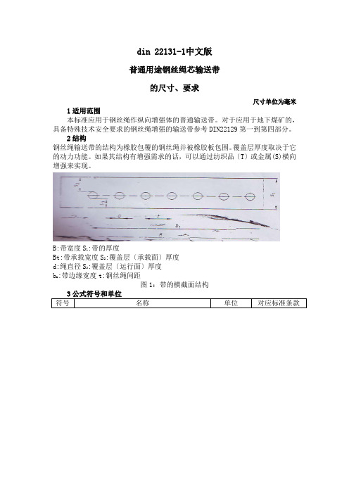
:带的厚度B:带宽度S1Bt:带承载宽度S:覆盖层〔承载面〕厚度2:覆盖层〔运行面〕厚度d:绳直径S3b:带边缘宽度t:钢丝绳间距k图1:带的横截面结构表2:尺寸4带的类型4.1带的类型表2给出了最新的带的类型。
带的类型范围从ST500到ST8000。
如果有要求的话,特殊的细节是可以接受的。
4.2涂层4.2.1涂层厚度运行面的S3涂层的厚度不应低于表2中给出的最小厚度。
对于特殊功能的厚涂层也是可以接受的。
承载面的S2的厚度由每一个表2中的最小厚度值组成,也可能增加一个额外值,其受变化因素的影响和取决于DIN22101.当需要考虑输送带装置时,涂层厚度应按要求增加。
4.2.2商品的分类涂层的分类是由其应用功能决定的。
4.3带的厚度钢丝绳的直径d和涂层宽度S2和S3决定了带的宽度S1.绳的宽度尺寸变化范围为±10%。
对于宽度≤20mm的带,较小的带的宽度变化是1.0mm。
对于宽度≥20mm 最大为1.5mm.4.4带的长度±2%的传送长度变化是允许的,对于个别带的长度与传送环境应一致。
4.5带的边缘带的边缘宽度bk应不低于15mm.4.6数值的调整4.71400m钢丝绳增强带〔ST〕,宽度为2200mm.破坏强度为3500N每毫米带宽,承载面10mm涂层,运行面7mm。
分类为Y.1400m钢丝绳增强输送带根据要求来确定〔带DIN22131-2200ST350010/7Y〕5.要求5.1钢丝绳的破坏载荷带的破坏载荷至少等于货物的最小破坏载荷并且绳的分布在表2中,增加大约10%。
机组RB功能试验三措两案范本
机组RB功能试验三措两案范本1 系统概况公司_机组600MW亚临界参数燃煤发电机组。
锅炉为上海锅炉厂制造。
汽轮机为上海汽轮机厂制造的亚临界蒸汽参数、一次中间再热、单轴双缸双排汽汽轮机。
发电机由上海电机股份有限责任公司制造的600MW水氢氢冷却汽轮发电机。
机组热工控制为单元制,采用机、炉、电集中控制方式,机组热工控制设备为北京和利时MACSV-5型分散控制系统(DCS)和部分可编程控制器。
工程设计单位为西北电力设计院;工程施工单位为北京电力建设公司;上海调试所负责机组的分系统调试和整套启动调试。
和利时MACSV-5型分散控制系统包括以下系统及功能:闭环控制系统(MCS),炉膛安全管理系统(FSSS),汽机及锅炉侧顺序控制系统(SCS),数据采集处理监视系统(DAS),电气侧顺序控制系统(ECS)等。
机组DCS共由五台操作员站、一台工程师站、若干控制机柜及4台打印机组成。
2 试验目的保证控制系统测点及报警信号正确,设备可远方操作,相应反馈信号正确可靠,各系统保护及联锁安全、可靠,动作正常,投入运行,主要辅机跳闸后机组可以按照事先预定负荷及压力进行协调控制,保证机组的安全运行。
3 试验组织机构及分工3.1领导小组:组长:生产副总副组长:总工成员:专业管理人员职责:负责确认试验的可行性,审批试验方案和措施,对存在的风险进行评估,并采取相应的防范措施,在试验出现异常情况下有权命令停止试验。
3.2试验指挥组:组长:副三总师副组长:生技部、设备部经理成员:专业管理人员职责:下达试验步骤的操作命令,确定操作的正确性和安全性,在试验出现异常情况下有权命令停止试验。
3.3运行操作组:组长:发电部经理成员:专业管理人员职责:负责根据试验方案编写试验操作票、风险预控票,并进行落实,负责试验过程运行设备的各项操作及事故处理,安排运行水平较好的运行人员参加试验,尽可能减少RB、电泵大联锁失败时带来的损失,监督落实试验过程中设备的消缺情况,负责做好试验过程中各运行参数的记录。
RB3保温杯用户手册说明书
USER MANUALIMPORT ANT SAFETY INSTRUCTIONSWARNING: When using electric products, basic cautions should always be followed, including the following.1. Read all safety and operating instructions before using this product2. The product should be powered by a three pin `grounded (or earthed) plug connected to a power socket with a grounded earth outlet.3. All safety and operating instructions should be retained for future reference4. Obey all cautions in the Operating instructions and on the back of the unit5. All operating instructions should be followed6. This product should not be used near water, i.e. a bathtub, sink, swimming pool, wet basement, etc.7. This product should be located so that its position does not interfere with its proper ventilation. It should not be placed flat against a wall or placed in a built up enclosure that will impede the flow of cooling air.8. This product should not be placed near a source of heat such as stove, radiator, or another heat producing amplifier.9. Connect only to a power supply of the type marker on the unit adjacent to the power supply cord.10.Never break off the ground pin on a power supply cord.11.Power supply cords should always be handled carefully. Never walk or place equipment on power supply cords. Periodically check cords for cuts or signs of stress, especially at the plug and the point where the chord exits the unit.12.The power supply cord should be unplugged when the unit is to be unused for long periods of time.13.If this product is to be mounted in an equipment rack, rear support should be provided.14.The user should allow easy access to any mains plug, mains coupler and mains switch used in conjunction with this unit thus making it readily operable.15.Metal parts can be cleaned with a damp cloth. The vinyl covering used on some units can be cleaned with a damp cloth or ammonia based household cleaner if necessary. Disconnect the unit from the power supply before cleaning.16.Care should be taken so that objects do not fall and liquids are not spilled into the unit through any ventilation holes or openings. On no account place drinks on the unit.17. A qualified service technician should check the unit if:18.The user should not attempt to service the equipment. All service work is done by a qualified service technician.19. Exposure to extremely high noise levels may cause a permanent hearing gloss. Individuals vary considerably in susceptibility to noise induced hearing loss, but nearly everyone will lose some hearing if exposed to sufficiently intense noise for a sufficient time. The U.S. Government's Occupational Safety and Health Administration (OSHA) has specified the following permissible noise level exposure. Duration Per Day In Hours Sound Level dBA, slow response8 9069249539721001 ½1021105½110¼ or less 115According to OSHA, any exposure in excess of the above permissible limits could result in some hearing loss. Ear plugs or protectors in the ear canals or over the ears must beworn when operating this amplification system in order to prevent a permanent hearing loss if exposure exceeds the limits set forth above. T o ensure against potentially dangerous exposure to high sound pressure levels it is recommended that all persons exposed to equipment capable of producing high sound pressure levels such as this amplification system be protected by hearing protectors while this unit is in operation.!The power cord has been damaged!Anything has fallen or spilled into the unit !The unit does not appear to operate correctly!The unit has been dropped or the enclosure damaged.BEFORE SWITCHING ONAfter unpacking your amplifier check that it is factory fitted with a three pin 'grounded' (or earthed) plug. Before plugging into the power supply ensure you are connecting to a grounded earth outlet.If you should wish to change the factory fitted plug yourself, ensure that the wiring convention applicable to the country where the amplifier is to be used is strictly conformed to. A s an example in the United Kingdom the cable colour code for connections are as follows.NOTEThis manual has been written for easy access of information. The front and rear panels are graphically illustrated, with each control and feature numbered. For a description of the function of each control feature, simply check the number with the explanations adjacent to each panel.Y our Laney amplifier has undergone a thorough two stage, pre-delivery inspection, involving actual play testing.When you first receive your Laney Bass amp, follow these simple procedures:(i) Ensure that the amplifier is the correct voltage for the country it is to be used in.ii) Connect your instrument with a high quality shielded instrument cable. Y ou have probably spent con siderable money on your amplifier and guitar - don’t use poor quality cable it won’t do your gear justice.Please retain your original carton and packaging so in the unlikely event that some time in the future your amplifier should require servicing you will be able to return it to your dealer securely packed.Care of your Laney amplifier will prolong it's life.....and yours!EARTH OR GROUND - GREEN/YELLOW NEUTRAL - BLUELIVE - BROWNINTRODUCTIONThe RB3 is a 65W bass combo with a 12 inch loudspeaker in a sturdy wooden cabinet. Its features include; two ¼” jack inputs for Normal / Hi level signals, a gain control and a switchable compressor, a flexible EQ system with Bass, swept Mid, & T reble, followed by an overall Volume control. Should you need to play along to CDs/MP3s you can plug the output of your player into the CD/line in socket. A Direct out allows you to connect to a PA or recording device, and there is an FX loop for connection of external FX. A headphone socket is provided for private practice, and an external speaker socket for connecting additional cabinets. An explanation of these features follows on pages 6-8.Dear Player,Thank you very much for purchasing your new Laney product and becoming part of the worldwide Laney family. Each and every Laney unit is designed and built with the utmost attention to care and detail, so I trust yours will give you many years of ney products have a heritage which stretches back to 1967 when I first began building valve amplifiers in my parent’s garage. Since then we have moved on from strength to strength developing an extensive range of guitar, bass, public address and keyboard amplification products along with a list of Laney endorsees that includes some of the world’s most famous and respected musicians. At the same time we believe we have not lost sight of the reason Laney was founded in the first place - a dedication to building great sounding amplification for working musicians. Warm Regards,Lyndon Laney CEONormal and High inputs are provided for connection of bass guitars. High output basses, either Active or Passive should be connected via the High socket. Low output basses should be connected using the normal input. High output basses may also be placed in the Normal input if pre-amp overloading is desired.This control is used to set the level of gain present in the pre-amp. producing distortion. The Gain control should be used in conjunction with the signal characteristics.Engages and disengages the on-board compressor, this compresses the input-signal giving a punchier sound. In association with the compressor are two LEDs, one indicating that the compressor is engaged and one indicating the compressor is active. The amount of compression is controlled by the Gain control. The higher the setting the more compression. With most guitars compression will begin at about 5-6 on the control. It is possible to have the compressor engaged but it only be active during certain periods of playing - typically the most dynamic sections.Controls the boost and cut of the low-frequency response of the pre-amplifier.Selects the mid-frequencies (200Hz to 2KHz) to be cut or boosted in conjunction with the paramid level controlT o access low mid-frequencies turn the frequency control anticlockwise, to access higher mid frequencies turn the frequency control clockwise.6FRONT P ANEL CONTROLS4567Controls the boost and cut of the high-frequency response of the pre-amplifier.Sets the overall listening level of the amplifier.RCA/Phono connections provided for connecting an external sound source such as; CD players, MP3 players, Minidisc etc.This socket provides a balanced low-impedance output-signal from the pre-amplifier taken before the Master Volume but afterany tone correction, used for direct-injection of the amplifier signal to a mixing-desk or additional power-amplifier.Send and return sockets are provided for connecting external effects-units. Y ou can also use the Send socket as a line out if you wish.Indicates power is connected and the amplifier is switched on.(Always switch off and disconnect power cord when not in use)Main power on/off switch.Power inlet socket. Connect to your power source. Make sure the specified voltage is correct for your country!The main safety fuse for the unit is inside this drawer.USE ONLY THE CORRECT SIZE AND RATING OF FUSE AS SPECIFIED ON THE PANEL.The mains fuse ratings are detailed in the specs section at the rear of this manual.Serial Number and model of your unit.This socket(s) should be used to connect an extension-cabinet. The impedance of the extension-cabinet must not be less than8 Ohms. Connecting cabinets that have a lower impedance than 8 Ohms will result in the amplifier overheating. Continual usein this manner may cause permanent damage. Connecting a cabinet with an impedance of greater than 8 Ohms will cause no damage to the amplifier but will result in a reduced output level. (When using an extension cabinet the internal speaker remains connected)Socket for connecting Headphones. When in use, the internal loudspeaker and any extension cabinets are automatically switched off.REAR P ANEL CONTROLSOutputoudspeakerCable NORMALHIUSER SETTINGSFound some cool settings you want to keep? Make a note of them here:General NotesAmplifier connection: In order to avoid damage, it is advisable to establish and follow a pattern for turning on and off your equipment. With all system parts connected, turn on source equipment, tape decks, cd players, mixers, effects processors etc. BEFORE turning on your Bass Amplifier. Many products have large transient surges at turn on and off which can cause damage to your speakers. By turning on your Bass Amplifier LAST and making sure its Volume control is set to minimum any transients from other equipment will not reach your loudspeakers. Wait until all system parts have stabilised; usually a couple of seconds. Similarly when turning off your system always turn down the Volume control on your Bass Amplifier and then turn off its power before turning off other equipment.Cables: Never use shielded or microphone cable for any speaker connections as this will not be substantial enough to handle the amplifier load and could cause damage to your amplifier system.Caution:These professional loudspeaker systems are capable of generating very high sound pressure levels. Use care with placement and operation to avoid exposure to excessive levels that can cause permanent hearing damage. (Refer to guidelines on page 2)Servicing: The user should not attempt to service these products. Refer all servicing to qualified service personnel.SPECIFICA TIONSSupply Voltage ~100V , ~120V , ~220V , ~230V , ~240V 50/60Hz Factory Option Mains Fuse ~220V>~240V = T2A L. ~100>120V = T5A L (Time delay)Power Consumption 100WOutput Power Rating 65WLoudspeaker 12” Custom Designed DriverFeatures Normal + Hi InputsSwitchable Compressor with Activity lightClip distortion limiterEQ Bass (Shelving)Paramid D.I.Y es, Balanced Jack.(Can be used for tuner)CD/T ape In Y esHeadphone Socket Y esExtension Loudspeaker Socket Y es (8 Ohms minimum)FX Loop Y es (0dBu Nominal) (Series-Insert)Input Impedance 1M Ohm/100pFRecommended Min Extension Speaker Power 80WRecommended Richter Extension Cab RB410 / RB115Size 510*495*305(H*W*D)Unit Weight 18.5Kg (Kg)Packing Weight 19.75Kg (Kg)±12dB at 65Hz,(±12dB at 200Hz >KHz Peaking)T reble (±12dB at 3.5KHz, Shelving)This product conforms to: European EMC directive(2004/108/EC), Low Voltage Directive (72/23/EEC) and CE mark Directive (93/68/EEC)2Page 11 /12LaneyOPERATING INSTRUCTIONSLaneyPOWER TO THE MUSIC@In the interest of continued product development, Laney reserves the right to amend product specification without prior notification.。
- 1、下载文档前请自行甄别文档内容的完整性,平台不提供额外的编辑、内容补充、找答案等附加服务。
- 2、"仅部分预览"的文档,不可在线预览部分如存在完整性等问题,可反馈申请退款(可完整预览的文档不适用该条件!)。
- 3、如文档侵犯您的权益,请联系客服反馈,我们会尽快为您处理(人工客服工作时间:9:00-18:30)。
ECONOLINE
DC/DC-Converter
Typical Characteristics
RB & RA Series
RB/RA-xx15D
Efficiency / Load
100 80 60
RB/RA-xx12D
Efficiency / Load
100 80 60 40
1212
0512
0515
RA-xx1.8S (H) RA-xx3.3S (H) RA-xx05S RA-xx09S RA-xx12S RA-xx15S RA-xx24S (H) (H) (H) (H) (H)
1 Watt SIP7 & DIP14 Single & Dual Output
RA-xx1.8D (H) RA-xx3.3D (H) RA-xx05D RA-xx09D RA-xx12D RA-xx15D RA-xx24D (H) (H) (H) (H) (H)
0% 20% 40% 60% Total Output current (%)
80%
100%
0% 20% 40% 60% Total Output current (%)
80%
100%
32
April-2005
元器件交易网
元器件交易网
Features
Unregulated Converters
● ● ● ● ● ● ●
Dual Output from a Single Input Rail Power Sharing on Output Industry Standard Pinout 1kVDC & 2kVDC Isolation Custom Solutions Available UL94V-0 Package Material Efficiency to 85%
xx = Input Voltage
Specifications (Core Operating Area)
Input Voltage Range Output Voltage Accuracy Line Voltage Regulation Load Voltage Regulation (10% to 100% full load) Output Ripple and Noise (20MHz limited) Operating Frequency Efficiency at Full Load No Load Power Consumption Isolation Voltage Rated Working Voltage Isolation Voltage Rated Working Voltage Isolation Capacitance Isolation Resistance Short Circuit Protection Operating Temperature Range (free air convection) Storage Temperature Range H-Suffix H-Suffix Single Dual 1.8V, 3.3V output types 5V output type 9V, 12V, 15V, 24V output types Single output types Dual output types ±10% ±5% 1.2%/1% of Vin max. 20% max. 15% max. 10% max. 100mVp-p max. ±75mVp-p max. 70% min. / 80% typ. 101mW min. / 126mW typ. / 171mW max. 87mW min. / 130mW typ. / 190mW max.
ECONOLINE
DC/DC-Converter
RB & RA Series
Efficiency (%) 70 75 70-78 76-78 78-80 80-84 74-85 70 70 74-78 76-79 80-82 80-84 80-84
Selection Guide
Part Number SIP 7 RB-xx1.8S RB-xx3.3S RB-xx05S RB-xx09S RB-xx12S RB-xx15S RB-xx24S RB-xx1.8D RB-xx3.3D RB-xx05D RB-xx09D RB-xx12D RB-xx15D RB-xx24D DIP 14 (2kV) Input Voltage (VDC) 1.8, 3.3, 5, 9, 12, 15, 24 1.8, 3.3, 5, 9, 12, 15, 24 1.8, 3.3, 5, 9, 12, 15, 24 1.8, 3.3, 5, 9, 12, 15, 24 1.8, 3.3, 5, 9, 12, 15, 24 1.8, 3.3, 5, 9, 12, 15, 24 1.8, 3.3, 5, 9, 12, 15, 24 1.8, 3.3, 5, 9, 12, 15, 24 1.8, 3.3, 5, 9, 12, 15, 24 1.8, 3.3, 5, 9, 12, 15, 24 1.8, 3.3, 5, 9, 12, 15, 24 1.8, 3.3, 5, 9, 12, 15, 24 1.8, 3.3, 5, 9, 12, 15, 24 1.8, 3.3, 5, 9, 12, 15, 24 Output Voltage (VDC) 1.8 3.3 5 9 12 15 24 ±1.8 ±3.3 ±5 ±9 ±12 ±15 ±24 Output Current (mA) 555 303 200 111 84 66 42 ±278 ±152 ±100 ±56 ±42 ±33 ±21
Deviation / Load
25.000 20.000 25.000 20.000
Deviation / Load
25.000 20.000
Deviation / Load
Deviation from Nominal (%)
Deviation from Nominal (%)
15.000 10.000 5.000 0.000 -5.000 -10.000
Deviation from Nominal (%)
0515
3.315
3.305
0505
15.000 10.000 5.000 0.000 -5.000 -10.000
3.309
0509
1215
1205
1209
0% 20% 40% 60% Total Output current (%)
80%
100%
100 80 60
RB/RA-xx09D
Efficiency / Load
100 80 60 40
1215
0505
1205
0509
0515 Efficiency % 3.315
40 20 0
1209 3.309
Efficiency %
20 0
3.305
Efficiency %
100%
20 0
0%
20%
3.315
3.312 Efficiency %
40 20 0
1215
Efficiency %
20 0
0%
20%
40%
60%
80%
100%
0%
20%
40%
60%
80%
100%
Total Output current (%)
Total Output current (%)
Deviation / Load
40%
60%
80%
100%
Total Output current (%)
0% 20% 40% 60% Total Output current (%)
80%
0% 20% 40% 60% Total Output current (%)
80%
100%
Deviation / Load
25.000 20.000 25.000 20.000
Output Power (%)
100 80 60 40 30 20 0
Derating-Graph
(Ambient Temperature)
50kHz min. / 100kHz typ. / 105kHz max.
(tested for 1 second) (long term isolation) (tested for 1 second) (long term isolation)
Safe Operating Area
85 Operating Temperature °C
-40
0
50
100
150
April-2005
31
元器件交易网
ECONOLINE
DC/DC-Converter
Specifications (Core Operating Area)
Efficiency %
20 0
20 0
0% 20% 40% 60% Total Output current (%)
80%
100%
0% 20% 40% 60% Total Output current (%)
80%
100%
0%
20%
40%
60%
80%
100%
Total Output current (%)
Deviation / Load
25.000 20.000
Deviation / Load
Deviation Nominal (%)
15.000 10.000 5.000 0.000 -5.000 -10.000
