阀门操作手册
PFF35-70法兰式平行闸阀使用说明书

目录1.概述 (2)2.主要技术规范 (2)3.结构特点 (4)4.操作使用说明 (5)5.维护保养 (5)6.安装说明 (6)7.易损件明细 (7)1 概述PFF系列法兰式平行闸阀是按石油天然气行业标准和API Spec 6A-2004第19版规范要求进行设计、制造的,选用抗轻度腐蚀材料,作为含硫石油、天然气的油气井井口装置和各种管汇的组成部件。
2 主要技术规范注:用于API Spec 16C的阀门仅限于EE级材料。
3 结构特点3.1 法兰式平行闸阀是明杆带(或不带)尾杆结构,其密封机理是依靠阀板与阀座间的贴合实现金属刚性密封。
3.2 阀盖和阀体采用螺栓连接,阀盖和阀体间采用双面密封特殊垫环,以确保密封性能的安全可靠。
3.3 闸阀为明杆结构,带有平衡尾杆的明杆阀开关具有明显标志,且减轻了阀的开关力矩,不带平衡尾杆的明杆阀具有结构紧凑的特点。
3.4 阀板和阀座表面堆焊特殊合金,使之具有良好的耐磨性和抗腐蚀能力。
阀杆采用特殊材料,承压件采用特殊热处理工艺,DD、EE级阀具备抗轻度H2S腐蚀。
3.5 轴承座上设有润滑轴承的油嘴,便于现场加注润滑脂。
它的对方有润滑脂排出孔,可以观察润滑脂的加注情况。
3.6 阀杆升降螺纹采用梯形螺纹,顺时针方向为“关”,逆时针方向为“开”。
3.7 PFF法兰式平行闸阀结构见图1、图2、图3。
4 操作使用说明4.1 逆时针旋转手轮打开闸阀,可见阀杆上升,直到阀杆到达上死点,闸阀全部打开,然后手轮倒退1/4~1/2圈。
4.2 顺时针旋转手轮关闭闸阀,可见阀杆下降,直到阀杆到达下死点,闸阀处于全关,然后手轮倒退1/4~1/2圈。
4.3 由于该阀只起截流作用,不起节流作用,所以只有两个工作状态:全开或全关,不允许以部分开启方式作节流用,否则会影响阀的密封性能和寿命。
4.4 在运输过程中,应避免在手轮上拴起重绳索。
4.5 操作过程中,旋转手轮快到行程终点时,不可以太快。
5 维护保养5.1 盘根注脂若阀杆或尾杆密封处泄漏,可以通过单流注脂阀加注二次密封脂.注脂时应将阀(尾)杆旋至上(下)死点,利用阀(尾)杆的倒密封,将密封脂EM08(或7903)注入盘根。
阀门操作维护保养手册
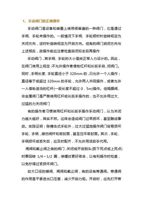
1、手动阀门的正确操作手动阀门是设备和装置上使用很普遍的一种阀门,它是通过手柄、手轮来操作的。
一般情况下手柄、手轮顺时针旋转规定为关闭方向,逆时针旋转规定为开启方向。
但有的阀门启闭方向与上述相反,故操作前应注意检查启闭标志后再操作手动阀门,其手柄、手轮的大小是按正常人力设计的。
因此,在阀门使用上规定:不允许操作者借助杠杆和长扳手启、闭阀门。
同时,手柄长度、手轮直径小于320mm的,只允许一个人操作;直径等于或超过320mm的手轮,允许两人共同操作,或者允许一人借助适当的杠杆(一般长度不超过0.5m)操作。
但隔膜阀、非金属阀门是严禁使用杠杆或长扳手操作的,也不允许用过大、过猛的力关闭阀门有的操作者习惯使用杠杆和长扳手操作手动阀门,认为关闭力越大越好,其实不然。
这样会造成阀门过早损坏,甚至酿成事故。
实践证明:除撞击式手轮外,过大过猛地操作阀门容易损坏手轮、手柄,擦伤阀杆和密封面,甚至压坏密封面。
其次,手轮、手柄损坏或丢失后,应及时配齐,不允许用活扳手代用。
闸阀和截止阀之类的阀门,关闭或开启到头(即下死点或上死点)时要回转1/4~1/2圈,使螺纹更好密合,以有利操作时检查,以免拧得过紧损坏阀门。
较大口径的蝶阀、闸阀和截止阀,有的设有旁通阀。
旁通阀的作用是平衡进出口压差,减少开启力矩。
开启时,应先打开旁通阀,然后再开启大阀门。
开启蒸汽阀门前必须先将管道预热,排出凝结水。
开启时要缓慢,以免产生水锤现象,损坏阀门和设备。
开闭球阀、蝶阀、旋塞阀时,当阀杆顶面的沟槽与通道平行时,表明阀门在全开启位置;当阀杆向左或向右旋转90。
时,沟槽与通道垂直时,表明阀门在全关闭位置。
有的球阀、蝶阀、旋塞阀以扳手与通道平行为开启,垂直为关闭。
三通、四通阀门的操作应按开启、关闭、换向的标记进行,操作完毕后应取下活动手柄。
对有标尺的闸阀和节流阀,应检查调整好全开或全闭的指示位置。
明杆闸阀、截止阀也应记住它们全开和全闭的位置,这样可以避免全开时顶撞死点。
多turn电动阀门控制器用户操作手册说明书

HT ANTI-CONDENSATION HEATER
IP3 VALVE MIDDLE TRAVEL POSITION SWITCH(No 3)
3 22
45Leabharlann 10232 14 36 07 13 35
BLK BLINKER SWITCH POT POTENTIOMETER (VALVE POSITION SIGNAL) CPT CURRENT POSITION TRANSMITTER
MADE BY 10/03/2020 JB WD CK-CKR STD., MSM-CCW, 3PH,
CHECKED 10/03/2020 JP
NOCPT, HT115, LIM, TOR, IMP
APPROVED 10/03/2020 JP
range
FORMAT
DRAWING Nº
A4 N00300AX - 2
BLK 24-25
BLK 24-25
BE CONNECTED THROUGH BOTH CIRCUITS. STANDARD 250AVC/5A, 24VDC 0,25A. GOLD CONTACT SWITCHE (LOW ENERG. CIRCUITS) UNDER REQUEST
5
6
7
8
CK-WD
1
2
3
4
5
6
7
E D C
S1 POWER
U V W N PE
F1 F2 F3
KM2
L1 L2 L3
III ELECTRIC ACTUATOR M1
(centork supply)
V (250 VAC max allowable voltage) 0
ITQ系列电动转角阀门安装和操作手册说明书

Installation and operating manual(ITQ-0100, 0160, 0240, 0350, 0500, 08001100, 1500, 2000 & 3000) 3F, 371-36, Gasan-Dong, Geumchun-gu, Seoul, Korea Tel : 82-2-855-1365, 66 Fax : 82-2-855-1367 E-mail : ***************.krITQ series Electric quarter turn actuatorContents1. Before operating actuator (3)2. About ITQ actuators (4)1)Internal & external component 3) Specification5) Mounting Base (ISO5211) 2) Internal component4) Features & Structure6) Removable drive bushing5,67,893. Sizing and Application (10)4. Setting (11)1)Manual operation 3) Torque switches 5)Indicator 2) Limit switches4)Stopper bolts 125. Location of actuator on the pipeline (13)1) Location of actuator on the pipeline2) Orientation of actuator6. Electrical wiring (14)1) Before wiring3) Checking the rotating direction ofactuator 2) Electrical wiring4) Commissioning(Electrical)7. Others (15)1) Jamming2) Special tools for setting8. Caution9. After sales service ………. ……….15161) Free of charge 2) User’s charge3) Trouble shootings10. Maintenance (17)1) Lubrication 3) Maintenance2) Regular operation 4) OthersITQ series Electric quarter turn actuatorITQ series Electric quarter turn actuatori.About ITQ actuator1)External componentsITQ0100 ~ ITQ1100ITQ series Electric quarter turn actuator2) Internal componentITQ0160 ~ ITQ1100ITQ1500 ~ ITQ3000CAPACITOR TERMINAL BLOCKASSEMBLYMOTORTORQUE SWITCH ASSEMBLYLIMIT SWITCH ASSEMBLYPOTENTIOMETER ASSEMBLYCAPACIT TERMINAL BLOCK ASSEMBLYMOTORITQ series Electric quarter turn actuator3)Specification(On-Off)Enclosure Weather proof enclosure IP67, NEMA 4 AND 4X, O-RING SealedMain power supply 110/220V AC 1Ph, 380/440V AC 3Ph 50/60Hz, ±10%Control power supply 110/220V AC 1Ph 50/60Hz, ±10%Duty cycle(On-Off) S2, 20~50% Max 30MinDuty cycle(Modulating) S4, 30~50%, 300~1200starts/hourMotor Squirrel caged induction motorLimit switches OPEN/CLOSE, SPDT, 250V AC 10A RA TINGTorque switches OPEN/CLOSE, SPDT, 250V AC 10A Rating(Except for ITQ0100)Stall protection(Temp.) Built in thermal protection, OPEN 150℃±5℃/CLOSE 97℃±15℃Travel angle 90˚±5˚(0˚~100˚)Position indicator Plate with indication arrowManual override De-clutchableSelf locking Provided by double worm gearing(No brake)Mechanical stopper 1 each for each travel end(OPEN and CLOSE), external adjustableHeater 5W (110/220V AC) Anti-condensationCable entries 2- PF3/4” TAPLubrication EP Type greaseTerminal block Screw and lever push type(Spring loaded)Ambient temperature -20℃~+70℃(Except for optional electronic board)Ambient humidity 90%RH Max, (Non-condensate)Dielectric strength 1500V AC 1minuteInsulation resistance 500V DC 30M OhmAnti-vibration X Y Z 10g, 0.2~34Hz, 30minuteExternal coating Dry powder (Polyester)4)Features and structure(1) General :ITQ series actuator is designed for the 90 degree turn application such as damper, ball, plug, butterfly valve and other equipment(2) Wide range of torqueMin. 100Nm to Max 3000Nm. In between there are 12 models and cater for various torque depending on application.(3) MaterialMaterial is hard-anodized AL alloy and external coating of epoxy powder is suitable for the severe condition especially against the corrosion. Housing is designed in accordance with standard of ex-proof and IP67.ITQ series Electric quarter turn actuator(16) AdaptionMounting base is designed according to ISO5211 but different dimension depending on application is also possible. Removable drive bushing provides convenient machining for adaption.(17) LubricationUsing EP type Grease Moly, no need to refill lubricant for the long time.(18) OthersITQ guaranty high performance, high quality product throughout various and severe test and inspection.5) Mounting base according to ISO5211 standardITQ1500,ITQ2000 & ITQ3000ITQ0350, ITQ0500 ITQ0800, ITQ1100Removable Drive bushings for adaptionITQ0100 ITQ0160, 0240 ITQ0350, 0500 ITQ0800, ITQ1100 ITQ1500, ITQ2000 & ITQ3000ITQ0100 ITQ0160, ITQ0240ITQ series Electric quarter turn actuator3. Sizing and applicationNote :1. Above table just show reference and no guaranty!2. Sizing should be done after careful reviewing valve factory, temperature, characteristics of fluid and etc.3. Having application under special condition such as high and low temperature, seawater, severe corrosion, high vibration), please consult with our technical dept before selecting actuator.4. Decision by user ignoring our recommendation, we have right to avoid any responsibility.ITQ series Electric quarter turn actuator3)Torque switchesTorque Switches are set by factory before delivery and therefore no need to set the switches again, but just do as follows for check if switches functions well.①Push the lever of close switches by screw driver until it sounds “click” then actuator should stopimmediately. If it stops, switches work well.②Check open switches as per just same with above.③No guaranty in performance once these switches are set again.④Before setting, if it is really necessary to adjust, please consult with factory.ITQ series Electric quarter turn actuator4)Stopper bolt setting①Before manual operation, get both nuts loose which are engaged with stopper bolts and turn stopper bolt tocome out by 3~ 4 threads.②Move actuator full close position by manual.Once cam hit the lever of limit switch to trip, stop manual operation.③Then turn close stopper bolt to go forward until it don’t’ not go further (End of stopper bolt contacts the 2ndworm wheel).④Turn close stopper bolt to come out by 2 threads and tighten the loosen nut.⑤Do as per same with above for open stopper bolt5)Indicator setting①Move actuator full close position and turn indicator by hand until orientation of indicator is aligned to thefigure of window.②Tighten the bolt (Be careful not to be injured by the cutting edge of indicator and leakage of electricity whenpower is on)③Figure of Window and indicator according to AWWA standardITQ0100ITQ0160~ITQ1100ITQ1500~ITQ3000ITQ series Electric quarter turn actuator5. Recommendation for installation of actuator in the pipeline1)Location of actuator on the pipeline2) Orientation of installation of actuator① No restriction, but it is recommended to install actuator in the position which cable entry face the groundorientation for watertight function and hand wheel faces front for easy manual operation without interruption. ② Reserve the space for maintenance.ITQ series Electric quarter turn actuator6. Electrical wiring1) Before wring①Cable entries are machined with PF3/4” tap and sealed by Plug before delivery.②Please remain the plug as it is if user doesn’t use both cable entries.③Please make sure to seal the entries by using rubber or metallic packing after wiring, so that water may notcome in.④When user use actuator as ex-proof, please make sure to use the certified connection component which is atleast same grade with actuator.⑤This is not our scope of supply, but if user don’t use suitable component, factory won’t guaranty theperformance of ex-proof actuator.2) Electrical wiring①Check if electrical specification like as power, wiring & etc are correct or not.②One sheet of wiring diagram is to be supplied together with actuator.③Do the wiring as per the given wiring diagram, such as power, control power , internal wiring and ground.④Make sure to supply electric power to heater for keeping inside of actuator clean and dry.⑤Make sure to check wiring to the terminal is strong enough.⑥Make sure that one relay operates one actuator only( Can not operate two or more actuators simultaneously)⑦Make sure to clean inside of actuator and no foreign material inside.3) Check rotating direction①In 3 phase actuator, operator should check the rotating direction of actuator before electrical operation.②If operating direction is wrong, limit switches doesn’t function and it results damage from jamming ormotor’s overheating.③So, put the actuator at 50% open(or Close) position by manual and supply power into the actuator andcheck it’s rotating direction.④If actuator moves open as per open signal, the direction it is O.K, but reverse, need to change the wiring.⑤Among 3 of power wires, change 2 wires each other.⑥Then check the rotating direction again in order to confirm it again.4)Commissioning①Make sure to check the rotating direction of actuator first before operation.②Check the function of limit and torque switches, direction of indicator and space heater.③Check lever movement is O.K (Manual override)④Check the lamps in the control panel.⑤After commission, please make sure to tighten the 4 bolts of the top cover and to do proper sealing.ITQ series Electric quarter turn actuator7.Others1) Jamming①In case that actuator moves wrong direction and moves over the travel limit, internal worm gear contacts thestopper bolt and engaged each other. This is so call jamming and can not move actuator at all.②How to solve-Off the power-If jamming is happened during close, take close stopper bolt to come out by about 2 ~3 threads-Pull over the lever and put it manual position.-Turn hand wheel to counterclockwise until 50% open position.-Check rotating direction again.-If everything is O.K, put stopper bolt original position.-If jamming is happened during open, procedure is same with close, but turn hand wheel to clockwise by manual.2) Special tools for setting①L-Wrench 1 set(Metric)②Screw drivers (--, +)③Spanner set (Metric), Monkey spanner 200mm, 300mm 1 each,④Wire stripper, Long nose, Light⑤Multi Meter (AC, DC V olt, Resistance)⑥DC signal generator (0~4mA DC) : RPC option⑦mA DC Meter (0~25mA DC) : RPC and CT8.Caution①Selection of valve and actuator : Review all specification of valve and actuator carefully before makingselection and reserve about 30% torque of actuator for safety purpose. If required torque is 90Kg-m, recommended actuator torque is about 117Kg-m.②Option : Please consult with factory before making selection, if possible.③Before necessary setting such as limit switch, please don’t operate actuator either fully open or fully close.④After electrical wiring, make sure to secure the sealing of cable entries.⑤Before operating actuator, please review this manual carefully and follow the instruction without fail.Please be careful at temperature, humidity, vibration, voltage drop.⑥Storage : Keep actuator dry, clean and cool.⑦Trouble : Please refer to following trouble shooting but please don’t dismantle the actuator withoutconsulting with factory.⑧If repair or maintenance is required, please check the model, electrical condition, serial Number and currentsituation to inform factory.ITQ series Electric quarter turn actuator10. Maintenance1)LubricationLubrication is already done by factory and generally no need to refill it again.But in the places such as very dry condition below R.H 15% or high temperature higher than 30o C, it is required to do lubrication once two year through Grease Nipple.2)Regular operationElectrical power always should be supplied to actuator and it is recommended to operate actuator once a week.3)MaintenanceIn order to use actuator for long time, regular maintenance once a year is required.Pleas check operating condition, corrosion, painting & etc.4)OthersShould you have any further queries, please contact us through Phone, fax and E-mail without hesitation.。
CCI阀门操作手册
阀门尺寸图中显示了允许的管段模具指标。
若因某种原因,管道的管段模具指标比阀门喷嘴高,必须通知我们出现的外力和力矩。 我们将根据这些指标检查阀体。若结果不可接受,应将重新调整管道系统。
5
对于阀门,我们建议在阀门上面和四周留有足够的空间以便于
拆卸
两个管绝不能连接成T-接头,防止对流(例如180°角)
阀门出口和接点之间的管长度必须不同。可避免导致回声。
4
温度测量点应尽量远离阀门,最小距离为4米。测量点不能离出口管接头和冷再加热器管太近,必须保证,当阀门关闭时,测量点的温度应比冷再热管的温度低(设置值)。
必须小心布置温度测量点,不要接触到水(阀门下游肘处的凝结水或水积聚,或未蒸发、离心的个别水)。
高旁阀紧紧固定在座上,因此上游不再需要隔离阀。若仍然装配了一个隔离阀(例如为了维护)必须保证高旁阀适当预热,并为运转做好准备(为运转做准备,隔离阀必须全开)。对具备安全功能的高旁阀(例如,所有TRD421)不允许有上游隔离阀。
入口管必须确保凝结水能流回流通蒸汽管,从而避免由于凝结水的形成导致的热震动。必须避免能出现水袋的管段。若做不到,管段必须装备具备充分能力和压差的恒动作排水设施。
瑞士,温特图尔,邮箱.Im Link 11.CH–8404,CCI
电话0041 52 26497 08.电传0041 52 264 97 10
第1章:使用说明
第2章:安装说明
第3章:主要部件说明
第4章:电子、电动-液压设备
第5章:通用维护说明
第6章:通用安装说明
第7章:拆卸与组装
第7章:液压油站
第8章:电子设备
6
在伺服阀和液压泵之间的泄露管中不允许有静态压力,否则会加重伺服阀的压力。
闸阀操作和维护手册
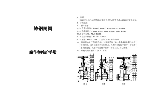
铸钢闸阀操作和维护手册1.总则该系统的阀门,在管线系统中用于关闭或开启管线,保持系统正常运行。
2.产品描述2.1 技术要求2.1.1 设计与制造:API600、API603、ASME B16.34、BS14142.1.2 连接端尺寸:ASME B16.5、ASME B16.47、ASME B16.252.1.3 结构长度:ASME B16.102.1.4 检查和试验:API 598、API6002.1.5 规格:MPS2″~48″,压力:Class150~25002.2 该系列的阀门带有法兰端、对焊端手动(通过手轮或齿轮箱传动的)铸钢闸阀。
阀杆以垂直的方向移动。
当顺时针旋转手轮时,闸板落下来关闭管线;当逆时针旋转手轮时,闸板上升,开启管线。
2.3 结构简图请见图1、图2、图3;图1 图2 图32.4 主要部件的名称和材料在表格1中(表1)3.存贮、维护、安装和操作3.1 存贮、维护3.1.1 阀门应被存贮在室内于干燥和通风处。
通道的端口应用盖子塞住。
3.1.2 长期存贮的阀门应进行定期检查和清理,特别是清理阀座密封表面,防止被损坏。
并且在机加工表面涂上防锈油。
3.1.3 如果存贮的时间超过18个月,阀门在安装使用前应进行测试,并做好记录。
3.1.4 安装后的阀门应定期进行检查和修理。
主要的维护点包括如下:1)密封表面2)阀杆和阀杆螺母3)填料4)阀体和阀盖的内部表面的污垢3.2 安装3.2.1 安装前重新确认阀门标识(如型号、公称通径、公称压力、材料)是依据管线系统的要求标识。
3.2.2 安装前仔细地检查阀门的通道和密封表面。
如有任何的赃物,应清理干净。
3.2.3 安装前,确保所有的螺栓已拧紧。
3.2.4 安装前,确保填料被压紧。
但不应妨碍阀杆的移动。
3.2.5 安装阀门的地方应是方便于检测和操作的,最好的位置应和管线是水平的,并且手轮在上,阀杆是垂直的。
3.2.6 对于正常的关闭阀门,阀门不适合安装在工作压力非常大的地方,以避免阀杆被损坏。
升降止回阀操作和维护手册

1.总则止回阀安装在管路系统,其主要作用是防止介质倒流, 保持系统的正常运行。
2. 产品描述2.1 该系列阀门为活塞式升降止回阀,正常运行时,阀瓣在介质作用下脱离阀座,管线开启;反之,随着管道介质压力的降低,阀瓣在弹簧力或自重作用下逐渐关闭,阻止介质回流。
由于阀瓣型似活塞,因此升降运行平稳,关闭准确定位。
2.2 该系列阀门是依据ASME B16.34标准规范进行设计。
结构见下图:2.3主要部件的名称和材料见下表:3.存贮、维护、安装和操作3.1 存贮、维护3.1.1阀门应被存贮在室内干燥和通风处。
通道的端口应用盖子塞住。
序号名称 材 料 1阀体 ASTM A216 Gr. WCB+13Cr ASTM A105+13Cr ASTM A105+STL ASTM A182 F304+STL ASTM A351 CF3M+STL ASTM A182 F316L+STL 2阀盖 ASTM A216 Gr.WCB ASTM A105 ASTM A182 F316L ASTM A182 F304 ASTM A351 CF3M 3阀瓣 ASTM A182 F6a ASTM A182 F304+STL ASTM A351 CF8M ASTM A182F 316L+STL 4弹簧 304SS 316SS INCONEL 5螺柱/ 螺母 ASTM A193 B7/ASTM A194 2H 、ASTM A193 B8/ASTM A194 8 ASTM A193 B8M/ASTM A194 8M3.1.2长期存贮的阀门应进行定期检查和清理,特别是清除阀座、阀瓣密封表面脏物,防止关闭时擦伤密封面。
并在阀瓣密封表面涂上防锈油。
3.1.3如果存贮的时间超过18个月,阀门在安装使用前应进行测试,并做好计录。
3.1.4安装后的阀门应定期进行检查和修理。
主要的维护点包括如下:1)密封表面2)阀瓣及弹簧3)阀体腔部表面的污垢3.2安装3.2.1安装前重新确认阀门标识(如型号、公称通径、公称压力、材料)是否依据管线系统的要求标识。
AVK闸阀操作指南

Ref.nos.DNLmmHmmDmmDtmmDhmmPN10 PN16dsmmPN10 PN1606-040-7001240140241831501101806-050-70012501502411021651251806-065-70012651702711221851451806-080-70012801802971382001601806-100-701121001903341582201801806-125-701121252003761882502101806-150-701121502104482122852402206-200-70012200230562268340295 29522 2206-250-7001225025066432400350 35522 2606-300-7012300270740370455400 41022 26直径为250mm和300mm阀门上端螺孔为公制螺孔(M20为PN10,M24为PN16)Steel pipeD.ex.LmmHmmFMm重量千 克60.325024114888.2802971714114.33003341925168.33504481949219.14005622470273.04506642788323.950074027128球墨铸铁球墨铸铁球墨铸铁标准:碳钢可选:不锈钢标准:丁晴橡胶可选:氟橡胶高强度钢结构材料说明CL主体及法兰构件CLD主体及法兰构件阀帽,底件及填料函阀门阀座阀座密封阀杆垫密片止推环紧固件及阀塞手轮50—380mm手轮400—600mm闸阀位置指示器罩指示器螺母2.阀杆 阀杆由不锈钢材质制造,具有最佳的延展性与抗拉伸性能。
阀杆上的阀板止停装置能指示阀板全开的位置,在操作过程中起到保护阀杆密封、阀板橡胶和阀门内涂层的作用。
阀杆螺纹是冷辊压成型的,保证了不锈钢的组织结构不变,增加了阀杆的强度。
由于辊压螺纹边缘光滑,从而减小了操作扭矩。
四川东方300MW汽轮机高旁、低旁阀门操作手册
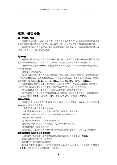
高旁、低旁操作高、低旁最小开度当锅炉点火启动后,蒸汽开始产生,随着“自启动”指令发出,此时操作员要把高旁和低旁打到预先设定的最小开度5%。
这么做的主要目的是为了充分冷却再热器和过热器。
随着信号DCS“自启动开始”并且高旁开到最小开度5%,此时如果高旁控制站的自动/手动处在自动位,则应切换为手动。
高旁升压随着着火越来越好并且锅炉产生的蒸汽越来越多,新蒸汽压力要按照确定的锅炉升负荷速率增加到最终高旁启动压力,在这个时候,低旁压力控制器在定压控制模式下。
当新蒸汽压力达到2MPa时,运行方式转换为升压模式,高旁压力控制器设定点切换为计算出的设定点。
自动/手动切换到自动高旁压力控制器的压力设定点按照汽机(冷态、温态、热态、极热态)的启动升压速率(冷态0.04MPa/min;温态0.08MPa/min;热态0.14MPa/min;极热态0.18MPa/min)变化到最终目标压力(冷态5.9MPa;温态8.52 MPa;热态8.52 MPa;极热态12.8MPa)。
当控制器输出值达到最小开度5%时,升压速率设为0,设定点压力保持,这意味着升压过程中断(此过程在锅炉产汽量小于设定点或产生着火问题时通常发生)。
在压力保持过程中,操作员只可以在压力控制器手动模式下调整值。
当中断消除并且高旁压力控制器输出超过10%时,升压过程继续进行,直到最终高旁目标压力(冷态5.9MPa;温态8.52 MPa;热态8.52 MPa;极热态12.8MPa)。
高旁定压控制当蒸汽压力由高旁压力控制阀控制时,汽机冲转(升速至1500rpm最后直至定速3000rpm),同期并网带负荷。
汽机的正常启动方式是中压缸启动在中压缸切换到高压缸的过程中,高压缸入口阀开,高旁阀关。
当蒸汽压力达到目标压力时,操作模式切换为定压控制方式自动/手动处在自动位高旁阀采用最终高旁目标压力控制方式下随着汽轮发电机同期并网信号发出,高旁最小开度功能切除当汽轮机进汽,旁路相应关闭当高旁阀关,并且汽轮机同期并网信号和切缸完成信号激活,高旁将进入跟随模式高旁跟随模式(相应低旁跟随模式)压力随锅炉负荷变化,压力的增长受高旁跟随最大压力梯度限制(0.6MPa)旁路应该保持关闭,除非压力突升高旁自动/手动控制站应在自动位高旁压力控制器的目标设定值应该是实际新蒸汽压力加上一个高旁压力偏移量(0.4MPa),所以高旁压力控制阀处于关闭位。
DVC2000_Positioner Instruction Manual _chinese(数字式阀门控制器操作手册_中文)
定位 0%... 定位 0%...
定位 50%... 定位 50%...
移动阀门至 0% 行程处
自动整定 1
完成
自动整定失败 使用手动整定 1
衰减 中间值
+5 不确定 -5
输入范围 上限 20 mA
5 mA ... 20 mA
保存并退出?
按按
1
保存并退出 不保存退出
保存并退出? 1
限位开关 1 作用点 90%
限位开关 1 关闭 大于 90%
限位开关 2 作用点 10%
125% ... -25%
高于 低于 无效
125% ... -25%
只有在安装了限位开关硬件的情况下才有用
限位开关 2 关闭
低于 10%
低于 高于 无效
保存并退出? 按按
阀门可能移动 1 按 3 秒种
不保存退出?
本手册的使用
本手册介绍了如何安装、设置和校验 DVC2000 系列数 字式阀门控制器。可以从第 4-2 页到上所列出的相关文 件中获得更多的关于安装、操作和校验 DVC2000 系列 数字式阀门控制器的信息。
本手册介绍了通过使用DVC2000本地操作界面进行的 基本设备设置和校验。该界面包含一个液晶显示屏 (LCD),四个按钮和一个针对位置变送器设置的开关。 界面支持七种语言,包括英语、法语、德语、意大利语、 西班牙语、汉语和日语。可以按照 Basic Setup(基本 设置)一章中的介绍设定语言类型。设备需要在不低于 8.5 V 电压和 3.5 mA 电流下运行。在执行某些程序时 需要最高达 20 mA 的直流电。
整定。
最终控制元件准备就绪,可安装到管线上。
警告
该产品是用于一个特定的技术规范范围。不正确的组态仪表可能会导致产品工作不正常、引 起财产损失或人员伤害。
阀门操作、维护和使用手册说明(阀门投标专用)
阀门储存、操作、维护和使用说明概述阀门是用来关闭和开启管道中介质。
切断阀没有节流的功能。
该类阀门顺时针旋转手轮,直到完全将通道切断,阀门关闭。
逆时针旋转手轮,直到碰到阻挡,阀门打开。
对于电动装置阀门,在断电等紧急情况下,可以使用备用手轮打开和关闭阀门。
注意!截止阀在不超过10%开启状态连续节流会对阀瓣和阀座引起剧烈振动、噪音、磨损和损坏。
止回阀作为控制管道介质单向流动的元件,当介质顺流时由管线自身压力的作用开启阀门,当介质倒流时依靠阀瓣自身重量、弹簧力和介质回流的压力作用在阀瓣背部,使阀瓣与阀座形成密封,达到止回截流的目的。
警告!禁止用夹泵的方式对阀门进行泵验。
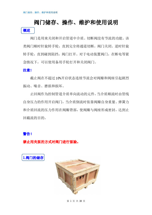
1.阀门的储存1.1发运准备阀门的包装应能防止阀门在运输过程和储存时不发生任何损坏。
并应注意以下几点:①闸阀:包装时,闸板应处于关闭状态。
②截止阀:包装时,阀瓣应处于关闭状态。
②止回阀:包装时,升降式止回阀、蝶形止回阀和对夹立式止回阀应将阀瓣有利于关闭状态摆放;旋启式止回阀和斜瓣式止回阀的阀瓣用丁字形木条顶住,丁字形木条一端撑紧在出口端孔内,以使阀瓣在运输过程中不会碰撞。
对于外接附件如阻尼缸、气缸等,应将附件可靠小心地完全固定。
1.11阀门法兰密封面/焊接坡口/螺纹端应涂合适的防护油脂(不锈钢材质除外),阀门两端应可靠地固接木质、木纤维或塑料端以防护连接端面和阀门内部。
对于闸阀和截止阀:齿轮箱或电动装置阀门包装时须小心地安全固定,以确保齿轮箱或电动装置不会损坏并不至于穿破木箱/板条箱。
1.12包装型式应在订单中明确规定,以便安全地运输至目的地和确保安装前的保存。
1.2吊运要求1.21包装完好的阀门板条箱:用叉车进行装卸。
木箱:在木箱的重心位置处设置装吊点进行装卸。
1.22已开箱的阀门①这些阀门的吊运要采取合适的手段和措施如应用货盘进行装卸,注意应避免加工面受到损坏。
②对大尺寸阀门,在吊运阀门时可用皮带或链条绕过阀体的颈部吊起,并应保持平衡以防止意外坠落或在吊运过程中松动。
阀门手册

《阀门手册》阀门手册本书全面、系统地介绍了阀门的基础知识、阀门种类和阀门应用等方面的内容。
具体内容包括:阀门介绍、阀门选用准则、手动阀门、控制阀、手动控制器和执行机构、灵活阀门及定位器、确定阀门尺寸、确定执行机构尺寸和常见阀门问题等。
阀门手册本书可以作为阀门使用和维修人员以及设备管理和工程技术人员的工具书。
也可作为阀门设计人员和从事压力容器、管道设计人员的参考书。
阀门的定义按定义,阀门是专门设计成的机械器件用以直流、启动、停止、混合或调节工艺流体的流量、压力或温度。
阀门能设计成处理液体或气体的运行。
按阀门的设计、功能和应用的特征,它的类型、尺寸和压力等级有很多种类。
最小的工业阀门重量可小到 1 lb(0.45kg),可舒适地放于人的手中。
而最大的可重到10t (9070kg)以上,高度达到24ft(601m)以上。
工业过程阀门能用于管线尺寸由0.5m[公称直径(DN15)]到超过48in(DN1200)。
不过超过90%以上的阀门用于工艺系统上是安装在4in(DN100)或较小尺寸的管线上。
阀门压力能够用于由负压到超过1300psi(897bar).工艺阀门尺寸的如何变化实例如图1.1所示。
今天现有阀门的淋浴已由简单的水龙头发展到备有信息处理机的控制阀,该信息处理机提供工艺过程的单环路控制。
今天最常用的类型是闸阀、旋塞阀、球阀、蝶阀、止回阀、泄压阀和截止阀。
阀门能由许多种材料制造,大多数阀门是由钢、铁、塑料、黄铜、青铜或大量的特殊合金制造的。
第二节根据功能的阀门分类1、按介质的功能设计的特征;2、双位式阀门(开-关阀门);3、止回阀;4、节流阀;5、控制环路中的末控制元件等;按介质的功能和设计的特征阀门可分为三类:双位式(开-关式)阀门,它具有控制物流闭合和允许其通过的功能;止回阀,它只允许物流向一个方向穿流;节流阀,它可在全开到全馆的任一点上调节物流。
按功能给阀门定义的一个混乱情况是特殊的阀门设计,注入截止阀、闸阀、旋塞阀、球阀、蝶阀和胶管形阀门可符合一个、二个或所有三类分类。
CCI阀门操作手册
预热
为了避免不期望的高旁阀热震动,阀门应持久预热到流通蒸汽温度下100ºC。为保证充分预热,在主蒸汽管上安装高旁阀,到主蒸汽管的距离为DI的5-7倍(入口管内径)。若此布置不能实现,必须单独安装一段连接到阀门入口喷嘴的预热管。
图2-1:预热
若设计中包括几段源自普通管的阀门歧管,必须进行测量,以消除不期望的回声导致的入
口管中的压力震荡。
布置不良的例子:(LS =流通蒸汽管)
图2-2:不适当布置阀
管路布置正常的例子:
图2-3:管路布置正常的例子
3
若高旁系统必须具备安全阀的功能(例如,失水时系统不能关闭),必须检查出口管以确保能在有限时间内耐最高阀门出口温度(例如,10,000小时,l%蠕变)。
核准通过,归档资料。
未经允许,请勿外传!
CCI 液动控制阀为准)
供应商瑞士,CCI AG
日期30.10.2007
定单号S.O 102280 P.O. 202028
记录号:6330
本手册的版权归属CCI公司
e-Mail: cciag@ccivalve.ch
3.备件定购
我们提供了备件定单。定购时请使用该定单。定购备件需要填写以下信息:
定购号
章和页
项和零件名称
若有,请填写相应图纸号。
4.一般说明
只允许经过相应培训和指导的专业人员对CCI AG 部件进行操作和维护。 本手册不包含专业工程师培训和知识相关的指导和参考。这同样也适用于操作电气系统的安全规定。必须遵从所有当地政府以及厂方适用的规定。必须严格履行涉及到事故预防的特别规定。本手册给出的指导有重大冲突时,请联系CCI AG。
阀门操作手册

1.目的为使我公司的阀门能够规范进行操作,特制订本规程。
2.适用范围适用于公司的球阀(手动、电动)、旋塞阀、节流截止放空阀的操作。
3.职责3.1 运行保障部负责监督本规程的执行情况。
3.2 各分子公司遵照本规程进行相应的操作。
4.操作步骤4.1 球阀开启操作4.1.1手动球阀的开启4.1.1.1双手握住手轮按照阀门开关指示器上的方向指示(一般为逆时针方向)转动,同时应密切注意蜗轮-蜗杆传动装置的有无转动、有无异常声响。
4.1.1.2按照阀门上的开关指示确定开到位。
4.1.1.3开到位后手轮往回转一点,以保证轮齿啮合部分不再处于受力状态。
4.1.2电动球阀的开启4.1.2.1打开红色转换开关的锁定装置,将红色转换开关打到“4.1.2.2把手柄扳到手动位置;4.1.2.3按逆时针方向转动手轮,将阀门开到5%,待阀门前后压力平衡后,朝“确认阀门全开后,把红色转换开关打到“位置,将锁定装置锁好。
4.2 球阀关闭操作4.2.1手动球阀的关闭4.2.1.1按照开关指示器的方向旋转操作(柄)手轮;4.2.1.2按照开关指示确定开关到位。
4.2.1.3关到位后手轮往回转一点,以保证轮齿啮合部分不再处于受力状态。
4.2.2电动球阀关闭操作4.2.2.1打开红色转换开关的锁定装置,将转换开关打到“4.2.2.2朝“4.2.2.3把红色转换开关打到”位置,将锁定装置锁好。
4.3旋塞阀的操作4.3.1旋塞阀的开启4.3.1.1双手握住手轮按照阀门开关指示器上的方向指示(一般为逆时针方向)转动。
4.3.1.2 按照阀门上的开关指示确定开到位。
4.3.1.3开到位后手轮往回旋转半圈,以保证轮齿啮合部分不再处于受力状态。
4.3.2旋塞阀的关闭4.3.2.1 按照开关指示器的方向旋转(一般为逆时针方向)手轮。
4.3.2.2按照开关指示确定开关到位。
4.3.2.3开到位后手轮往回旋转半圈,以保证轮齿啮合部分不再处于受力状态。
4.3.3 旋塞阀开关中的注意事项4.3.3.1 操作在正常情况下应一个人不用加力杆可正常开关。
BIFFI icon2000电动阀门操作手册
执行机构在出厂时完好,并各自附有测试报告。为了在执行机构安装到位前保持其出厂性能, 在贮运期必须进行适当处理。
BIFFI 执行机构防护等级是 IP68。但该防护等级必须在执行机构现场正确安装/连接及正确存 储的条件下,才能保证。
用于堵住电缆进线孔的标准塑料帽不是全天候防护的,它们只是用于防止运输过程中进入异 物。
设备安全-基本概念、设计通用原则。第一部分 - 基础术语、方法论; 设备安全-基本概念、设计通用原则。技术原理及规格; 工业机械的电气设备。第一部分:通用要求 机械指导 低压指导 电磁兼容指导 电气效能指导
2. 约定条件
我们对交付用户每一件产品,在正确安装、适当操作和维护的情况下,提供材料和制造工艺质 量方面的品质保证,并且符合当前的产品规格。产品保质期为一年,从第一用户安装之日算起,或
按拆下时的相反顺序装配内部零件,紧固压环,保证轴套仍旋转自由,然后安装到减速器上。如后 描述。
2.2 型号 B1 和 B2 联轴器
2.2.1 准备衬套
用合适的卡钳拆下卡环 拆下推力环 现在可加工适合连接要求的轴套孔。
2.2.2 重装内部零件 用合适的溶剂清洗拆下零件,然后用压缩空气干燥,确认没有金属屑或异物,然后将所有部件
2.1 型号“A”联轴器
2.1.1 准备轴套
使用弹簧卡钳卸下螺丝;从联轴器上取下衬套,
内部轴向轴承保持在联轴器底部,从轴套上拆下压环,然后拆下轴承
Copyright by BIFFI Italia. All rights reserved. A tyco INTERNATIONAL LTD. COMPANY
tyco flow control
第一部分:安装说明
第一章 通用安全说明
SMC XLF系列高压缩力低氢气阀门操作手册说明书
Doc. no.XL*****-OMJ0003-DHigh Vacuum L Type ValveXLF SeriesThank you for purchasing this SMC product.Be sure to read this Operation Manual carefully and understand its contents before operating this product to ensure the safety of the operator and this product.Please refer to the drawing and other informative documents for the construction and specifications of this product.Further, ensure your operating environment satisfies the requirements specified for the product.Keep this Operation Manual available whenever necessary.Safety Instructions - - - - - - - - - - - - - - - - - - - - - - - - - - - - 2 1. Product Specific Precautions 1 - - - - - - - - - - - - - - - - - - - - - - - - - - - - 4(Precautions on Design, Selection, Mounting, Piping, Wiring, Maintenance)2. Product Specific Precautions 2 - - - - - - - - - - - - - - - - - - - - - - - - - - - - 6(Maintenance parts)3. Specifications - - - - - - - - - - - - - - - - - - - - - - - - - - - - 74 Construction and Outer dimensions - - - - - - - - - - - - -- - - -- - - - - - - - - - - - 95. Period and scope of warranty - - - - - - - - - - - - - - - - - - - - - - - - - - - - 106. Parts replacement procedure - - - - - - - - - - - - - - - - - - - - - - - - - - - - 11Safety InstructionsThese safety instructions are intended to prevent hazardous situations and/or equipment damage. These instructions indicate the level of potential hazard with the labels of “Caution,” “Warning” or “Danger.”They are all important notes for safety and must be followed in addition to International Standards (ISO/IEC)*1), and other safety regulations.*1) ISO 4414: Pneumatic fluid power -- General rules relating to systems ISO 4413: Hydraulic fluid power -- General rules relating to systemsIEC 60204-1: Safety of machinery -- Electrical equipment of machines (Part 1: General requirements) ISO 10218-1992: Manipulating industrial robots -- SafetyCaution Caution indicates a hazard with a low level of risk which, if not avoided, could resultin minor or moderate injury.Warning Warning indicates a hazard with a medium level of risk which, if not avoided, could result in death or serious injury. DangerDanger indicates a hazard with a high level of risk which, if not avoided, will resultin death or serious injury.Warning 1. The compatibility of the product is the responsibility of the person who designs theequipment or decides its specifications.Since the product specified here is used under various operating conditions, its compatibility with specific equipment must be decided by the person who designs the equipment or decides its specifications based on necessary analysis and test results.The expected performance and safety assurance of the equipment will be the responsibility of the person who has determined its compatibility with the product.This person should also continuously review all specifications of the product referring to its latest catalog information, with a view to giving due consideration to any possibility of equipment failure when configuring the equipment.2. Only personnel with appropriate training should operate machinery and equipment.The product specified here may become unsafe if handled incorrectly.The assembly, operation and maintenance of machines or equipment including our products must be performed by an operator who is appropriately trained and experienced.3. Do not service or attempt to remove product and machinery/equipment until safety is confirmed.1.The inspection and maintenance of machinery/equipment should only be performed after measures to prevent falling or runaway of the driven objects have been confirmed.2.When the product is to be removed, confirm that the safety measures as mentioned above are implemented and the power from any appropriate source is cut, and read and understand the specific product precautions of all relevant products carefully.3.Before machinery/equipment is restarted, take measures to prevent unexpected operation and malfunction.4. Contact SMC beforehand and take special consideration of safety measures if the product is to be used in any of the following conditions.1. Conditions and environments outside of the given specifications, or use outdoors or in a place exposed to direct sunlight.2. Installation on equipment in conjunction with atomic energy, railways, air navigation, space, shipping, vehicles, military, medical treatment, combustion and recreation, or equipment in contact with food and beverages, emergency stop circuits, clutch and brake circuits in press applications, safety equipment or other applications unsuitable for the standard specifications described in the product catalog.3. An application which could have negative effects on people, property, or animals requiring special safety analysis.4. Use in an interlock circuit, which requires the provision of double interlock for possible failure by using a mechanical protective function, and periodical checks to confirm proper operation.Caution1.The product is provided for use in manufacturing industries.The product herein described is basically provided for peaceful use in manufacturing industries.If considering using the product in other industries, consult SMC beforehand and exchange specifications or a contract if necessary.If anything is unclear, contact your nearest sales branch.Limited warranty and Disclaimer/Compliance RequirementsThe product used is subject to the following “Limited warranty and Disclaimer” and “Compliance Requirements”.Read and accept them before using the product.Limited warranty and Disclaimer1.The warranty period of the product is 1 year in service or 1.5 years after the product isdelivered,whichever is first.*2)Also, the product may have specified durability, running distance or replacement parts. Please consult your nearest sales branch.2.For any failure or damage reported within the warranty period which is clearly our responsibility, a replacement product or necessary parts will be provided.This limited warranty applies only to our product independently, and not to any other damage incurred due to the failure of the product.3.Prior to using SMC products, please read and understand the warranty terms and disclaimers noted in the specified catalog for the particular products.*2) Vacuum pads are excluded from this 1 year warranty.A vacuum pad is a consumable part, so it is warranted for a year after it is delivered.Also, even within the warranty period, the wear of a product due to the use of the vacuum pad orfailure due to the deterioration of rubber material are not covered by the limited warranty. Compliance Requirements1.The use of SMC products with production equipment for the manufacture of weapons of mass destruction(WMD) or any other weapon is strictly prohibited.2.The exports of SMC products or technology from one country to another are govemed by the relevant security laws and regulation of the countries involved in the transaction. Prior to the shipment of a SMC product to another country, assure that all local rules goveming that export are known andfollowed.Warning●All models1. The material of the body and bonnet is A6063, and other metal components of the vacuumpart are made of SUS304. The sealing material of the vacuum part is FKM as standard, but this can be changed to other materials (refer to “How to Order”). Confirm whether the fluid to be used is compatible with the materials before use.Grease for vacuum is applied to the sliding part of the vacuum (Fluorine grease: Y-VAC2). 2. Select materials for the pilot pressure piping and fittings whose heat resistance is suitable forthe applicable operating temperature.●Models with auto switch1.Keep the temperature of the switch below 60oC.●With heater (thermistor)1.When using a model with a heater, a mechanism to prevent overheating should beinstalled.SelectionCaution●All models1. When controlling valve responsiveness, take note of the size and length of piping, as wellas the flow rate characteristics of the actuating solenoid valve.2. Actuating press should be kept within the specified range.0.4 MPa to 0.5 MPa isrecommended.3. Keep within the specified range of the pilot pressure.●High temperature type1. If using gases that cause a large amount of deposits, heat the valve body to prevent depositsin the valve.Mounting● All models1. In high humidity environments, keep the valve packed until the time of installation.2. For models with switches, secure the lead wires so that they have sufficient slack, withoutany unreasonable force applied to them.3. Perform piping so that excessive force is not applied to the flange sections. When there isvibration from heavy objects or attachments, etc., fix piping so that vibration will not apply torque directly to the flange section.4. Vibration resistance allows for normal operation of up to 30 m/s2 (45 to 250Hz), butcontinuous vibration may cause a decline in durability.Arrange piping to avoid excessive vibration or impacts.●High temperature type (temperature specification / H0 H4 H5)1. In models with a heater (thermistor), take care not to damage the insulation components of thelead wires and connector section.2. The set temperature for models with a heater should be established without any drafts or heat insulation. It will change depending on conditions such as heat insulation measures and the heating of other piping. Fine adjustment is not possible.3. When installing heater accessories or mounting a heater, check insulation resistance at the actual operating temperature. A current leakage breaker or fuse should be installed.4. If the valve is to be insulated, only the body should be insulated, excluding the bonnet part.5. In models with a heater, when the heater is in operation, the entire valve becomes hot. Be careful not to touch it with bare hands, as burns will result.1.Before mounting, clean the surface of the flange seal and the O-ring with ethanol, etc. 2. There is an indentation of 0.1 to 0.2mm in order to protect the flange seal surface, and it should be handled so that the seal surface is not damaged in any way.If the fluid or reaction product (deposit) may cause the valve to become unsafe, the valve should be disassembled, cleaned and re-assembled by an operator who has sufficient knowledge and experience (e.g. a specialist).1. When removing deposits from the valve, take care not to damage any part of it.2. Replace the bonnet assembly when the valve is approaching the end of its service life. * For details regarding endurance cycles, please reference Section 5 of this Operation manual titled Period and scope of warranty. (pages 10)3. If damage is suspected prior to the end of the service life, perform early maintenance.4. SMC specified parts should be used for service. Refer to the Construction / Maintenance parts table.5. When removing the valve seal and external seal, take care not to damage the sealing surfaces. When installing the valve seal and external seal, be sure that the O-ring is not twisted. (Refer to Section 6 Parts Replacement Procedure (pages 11 to 14) for details.)WarningSMC specified parts should be used for service. Refer to the construction drawing.1. Replace the bonnet assembly when changing the sealant material. Due to the differentmaterials used, changing only the seal may prove inadequate.Bonnet assembly/construction part number:1Temperature specifications IndicatorValve size16 25 40 50General use without XLF16-30-1 XLF25-30-1 XLF40-30-1 XLF50-30-1 with XLF16A-30-1 XLF25A-30-1 XLF40A-30-1 XLF50A-30-1High temperature without XLF16-30-1H XLF25-30-1H XLF40-30-1H XLF50-30-1H with XLF16A-30-1H XLF25A-30-1H XLF40A-30-1H XLF50A-30-1HTemperature specifications IndicatorValve size63 80 100 160General use without XLF63-30-1 XLF80-30-1 XLF100-30-1 XLF160-30-1 with XLF63A-30-1 XLF80A-30-1 XLF100A-30-1 XLF160A-30-1High temperature without XLF63-30-1H XLF80-30-1H XLF100-30-1H XLF160-30-1H with XLF63A-30-1H XLF80A-30-1H XLF100A-30-1H XLF160A-30-1H Note1) The magnet for auto switch is not provided. When the magnet for auto switch is necessary, add “-M9//” at the suffix of the part number.Note2) An auto switch for high temperature is available with a different part number.Note3) List the optional sealant material symbol after the model number, except for the standard sealant material (FKM: compound No. 1349-80).Note4) The bonnet assembly includes tha valve seal.External seal / Valve sealDescription ConstructionNo. MaterialValve size16 25 40 50External seal(3) Standard XLF16-6 XLF25-6 AS568-035V AS568-039V Special- - AS568-035 ** AS568-039 **Valve seal (2) Standard B2401-V15V B2401-V24V B2401-P42V AS568-227V Special B2401-V15 ** B2401-V24 ** B2401-P42 ** AS568-227 **Description ConstructionNo. MaterialValve size63 80 100 160External seal(3) Standard AS568-043V AS568-045V AS568-050V AS568-167V Special AS568-043 **AS568-045 ** AS568-050 ** AS568-167 **Valve seal (2) Standard AS568-233V B2401-V85V AS568-349V B2401-G155V Special AS568-233 ** B2401-V85 ** AS568-349 ** B2401-G155 **Note1) List the optional sealant material symbol after the model number, except for the standard sealant material (FKM: compound no. 1349-80).Note2) Refer to the Construction of each series for the construction numbers.Note3) We do not guarantee the quality if the seal material is changed by customer.Note1) Due to the different materials used, changing only the seal may prove inadequate.Barrel Perfluoro R is a registered trademark of MATSUMURA OIL Co.,Ltd.Kalrez R is a registered trademark of E. I. du Pont de Nemours and Company.Chemraz R is a registered trademark of Greene, Tweed & Co.,ULTIC ARMOR R is a registered trademark of NIPPON VALQUA INDUSTRIES, LTD. Model XLF-16 XLF-25 XLF-40 XLF-50 XLF-63 XLF-80 XLF-100 XLF-160 Flange (valve) size 16 25 40 50 63 80 100 160 Actuating type Normally closedFluid Vacuum of inert gasOperating temperature o C 5 to 60 (5 to 150 for high temperature type)Operating pressure Pa (abs) Atmospheric pressure to 1 x 10⁻⁵Conductance l/s Note 1 5 14 45 80 160 200 300 800LeakagePa・m3/s Internal 1.3 x 10⁻¹⁰ for the standard material (FKM)at ambient temperatures , excluding gas permeation External 1.3 x 10⁻¹⁰ for the standard material (FKM)at ambient temperatures , excluding gas permeationFlange type KF (NW) KF (NW) , K (DN)Main material Body: aluminum alloy, Main part: SUS304 and FKM (standard sealing material) Note 2Surface treatment for body Outside: hard anodized Inside: basis material Actuation pressure MPa(G) 0.4~0.7Air consumption cm3Note 3 for0.5MPa19 46 200 360 660 1350 3000 5150Port size M5 Rc 1/8 Rc 1/4 Weight kg 0.25 0.45 1.1 1.6 3 4.8 10 18 Note 1)The conductance is “molecular flow” measured with an elbow pipe which has the same dimension with each flange.Note 2) A seal sliding part and an external seal for vacuum use vacuum grease (Y-VAC2).Note 3) Air consumed by a reciprocating motion of a cylinder.3-2. Heater specificationsItem XL□-25 XL□-40 XL□-50 XL□-63 Rated voltage of the heater 90 to 240 ACVS y m b o l H4Heater assembly number - XLA25-60S-1 XLA25-60S-1 XLA25-60S-2 No. of heater assemblies - 1 pc. 1 pc. 1 pc.Initial power /Powerconsumption (W)100 VAC - 200/40 200/50 400/100200 VAC - 800/40 800/50 800/100H5Heater assembly number XLA25-60S-1 XLA25-60S-2 XLA25-60S-2 XLA25-60S-3 No. of heater assemblies 1 pc. 1 pc. 1 pc. 1 pc.Initial power /Powerconsumption (W)100 VAC 200/40 400/70 400/80 600/130200 VAC 800/40 1600/80 1600/80 2400/130Item XL□-80 XL□-100 XL□-160 Rated voltage of the heater 90 to 240 ACVS y m b o lH4Heater assembly number XLA25-60S-3 XLA25-60S-2 XLA25-60S-2 No. of heater assemblies 1 pc. 2 pcs. 3 pcs.Initial power/Powerconsumption (W)100 VAC 600/150 800/220 1200/350200 VAC 2400/150 3200/220 4800/350H5Heater assembly number XLA25-60S-2 XLA25-60S-2 XLA25-60S-2 No. of heater assemblies 2 pcs. 3 pcs. 4 pcs.Initial power/Powerconsumption (W)100 VAC 800/180 1200/300 1600/400200 VAC 3200/180 4800/300 6400/400 Note 1) Initial power and power consumption are nominal values.Note 2) Heaters are not available for the size 16 models.The heaters are PTC thermistor type design. Thesethermistors self regulate their temperature by switchingthe resistance at certain critical temperatures, so aseparate temperature controller is unnecessary.If the temperature of the PTC heaters fitted exceeds200o C, then it may fail. The maximum operatingtemperature for the valve is 150o C. If the heatertemperature is over 200o C or valve temperature is over150o C, please use thermostat to control the heaters toprevent overheating.With PTC type heaters, there is an initial surge ofcurrent (inrush current) after the power is supplied. These inrush current will reduce overtime. If multiple heater assemblies are used, the inrush current to the heaters will be magnified and care should be taken. When multiple heater assemblies or valves are used, do not apply power to the heater assemblies simultaneously. Keep approximately 30 seconds between applications of power to each heater assembly. This will allow for incremental spacing to prevent harmful large initial surge.4.hardened andnickelAAHφGBAuto switch(option)Model A B C D E Fn Fd G H XLF-16 40 103 38 1 - 30 - 17 40 XLF-25 50 113 48 1 12 40 - 26 39 XLF-40 65 158 66 2 11 55 - 41 63 XLF-50 70 170 79 2 11 75 - 52 68 XLF-63 88 196 100 3 11 87 95 70 69 XLF-80 90 235 117 3 11 114 110 83 96 XLF-100 108 300 154 3 11 134 130 102 131 XLF-160 138 315 200 3 11 190 180 153 112Unit: mmThe warranty period is 3 million cycles (for size 16, 25 and 40), 2 million cycles (for size 50, 63 and 80) or 1 million cycles (for size 100 and 160) (under SMC endurance test conditions), 18 months after delivery or 12 months in service, whichever comes first.Note ) The endurance will depend on the operating conditions (such as if the flow rate is large). If the valve has been used outside of the specifications, or if a failure occurs as a result of mounting onto a machine or replacement of an assembly, O-ring etc. by the user, the guarantee cannot be applied.For any failure reported within the warranty period which is clearly our responsibility, the whole valve will be replaced. This guarantee does not apply to any damage incurred due to the failure of the valve.Result of endurance test (with the circuit shown on the right)The valve was opened and closed in an internal vacuum state at an ordinary (room) temperature and checked for internal and external leakage and operation.It was confirmed that XLF-16, XLF-25 and XLF-40 satisfied the product specification up to 3 million cycles, XLF-50 , XLF-63 and XLF80 did up to2 million cycles. XLF-100 and XLF-160 did up to 1 million cycles. The test was performed with FKM, the standard sealing material.<Reference>The pumping direction is not limited, but if the pumping creates a flow stream, the durability of the product could be impaired.Therefore, the pumping direction shown on the right figure (bellows side pumping) is recommended. Also, the operating conditions should be checked beforehand because it affects the life.Vacuum pumpBellows side Valve sideChamberRecommended direction of exhaust6-1. PrecautionsBe sure to follow [1. Precautions 1] when disassembling the product for maintenance. Along with the precautions above, comply with the following precautions too.Warning•If it is expected that product materials may get stuck to the product, ensure safety isassured before handling. It is recommended to wear gloves and a mask.•Pay attention to the handling of components according to the procedure in the next itemonwards. Do not apply excessive force or impact. This will not only damage the productbut also decrease its performance and life expectancy.•It is not possible to disassemble the bonnet assembly of this product. If the componentsand assembly are damaged, or damage is expected, exchange the bonnet assemblyitself.•Do not disassemble the parts that are not explained in this operation manual. Theperformance and life may decrease. Also, it may cause danger.The heater is removed by loosening bolt a. Bolt a is behind the cover. Remove the cover using a watchmaker's screwdriver.0.4MPa of air pressure to the pilot Loosen bolt b in numerical order to disassemble the body and the bonnet assembly.1Bolt bHeaterPilot portBodyBonnet assembly 234eliminating any a clean cloth with clean (Ensure there is no fibers or dust. )Step 3Wipe off any dust from the external O-ring seal and the mounting surface of the Body. Place the O-ring on the O-ring mounting surface.132Installation of the O-ringEthanolApply 0.4MPa of air pressure to the pilot port. Tighten bolt b in numerical order to assemble the bolt b, tighten manually until the compressed, then perform extra tightening in diagonal order.For models with heater, tighten bolt a to mount the heater to the body. Insert the cover.1Bolt bBolt aHeaterBonnet assembly 234BodyCSafety Instructions PoDLimited warranty and Disclaimer SR1st Printing :JT 4-14-1, Sotokanda, Chiyoda-ku, Tokyo 101-0021 JAPANTel: + 81 3 5207 8249 Fax: +81 3 5298 5362URL Note: Specifications are subject to change without prior notice and any obligation on the part of the manufacturer.© 2012 SMC Corporation All Rights Reserved。
工业专用阀门手册
工业专用阀门手册一、引言概述嗨,小伙伴们!今天咱们来唠唠工业专用阀门。
你知道吗,在工业的大舞台上,阀门就像是一个个小卫士,默默地控制着各种流体的流动呢。
它们可是工业领域不可或缺的重要组成部分,没有它们,很多工业流程就没法顺利进行啦。
二、使用范围说明工业专用阀门的使用范围那可广了去了。
在石油化工行业,那些管道里流淌着原油、各种化工原料的时候,阀门就负责控制这些原料的流量,该关就关,该开就开。
在水处理厂也少不了它们,不管是净化水的流入流出,还是污水的处理过程,阀门都在精确地把控着水流的节奏。
还有发电厂,蒸汽啊、冷却水啊之类的流体在管道里穿梭,阀门就是确保这些流体按照正确的路径和量来运行的关键。
三、操作步骤指南1. 手动阀门操作首先呢,你得找到阀门的操作手柄或者手轮。
一般来说,顺时针旋转手轮是关闭阀门,就像拧紧螺丝一样,而逆时针旋转呢就是打开阀门啦。
在操作的时候,要平稳用力,可不能猛转,不然可能会损坏阀门内部的结构哦。
对于一些比较大的手动阀门,可能需要两个人配合操作,一个人负责固定住阀门的主体,防止在操作过程中晃动,另一个人来转动手轮。
2. 电动阀门操作在操作电动阀门之前,要先检查电气连接是否正常。
看看电线有没有破损,插头有没有插好。
然后呢,找到电动阀门的控制箱。
控制箱上一般有开、关、停这几个按钮。
按“开”按钮的时候,阀门就会慢慢打开,你可以通过观察阀门上的开度指示器,或者连接的监控设备来查看阀门的开启程度。
要关闭阀门就按“关”按钮,同样要注意观察。
如果在操作过程中出现异常情况,赶紧按“停”按钮,让阀门停止动作。
3. 气动阀门操作气动阀门是靠气体压力来驱动的。
首先要确保气源的压力是正常的,一般在操作面板上会有气源压力的显示。
然后找到气动阀门的控制旋钮或者按钮,按照标识来操作。
比如有的是向上推是开,向下拉是关。
在操作的时候,要注意听阀门动作的声音,如果有异常的嘶嘶声或者咔咔声,可能是阀门内部有问题了。
四、功能特点介绍1. 密封性好工业专用阀门的密封性可是它的一大亮点。
意大利ELEKTROGAS伊莱克斯EVRM-NA系列电磁阀操作手册
意大利ELEKTROGAS伊莱克斯EVRM—NA系列电磁阀操作手册意大利ELEKTROGAS伊莱克斯EVRMNA系列电磁阀操作手册上海维特锐供应ELEKTROGAS一手货源,品质超好,使用安全更放心,维特锐20余年工业备件代理销售老公司,德国采购公司原厂订货,布置航运到货中国,自身清关报关一站式服务。
为您供给更多高品质进口工业品。
由于意识到质量取决于每一个方面细节,ELEKTROGAS将注意力集中在实施严格的掌控程序上,以确保任何单个组件符合项目要求。
由于对技术学问的连续投资以及生产设备以及测试和测量系统的更新,这种方法得以实现。
意大利ELEKTROGAS伊莱克斯EVRMNA系列电磁阀操作手册阀门由铝合金压铸(或OT版本的热压黄铜)制成适用于从DN10到DN300的各种入口/出口连接。
密封件由NBR基橡胶制成,经认证可与气体一起使用(EN 549)。
适用于1、2和3系列中的空气和非腐蚀性气体(EN 437)。
适用于腐蚀性气体的特别版本,不含有色金属,并配有FPM密封。
管道连接符合EN161要求的第2组。
依据2023/34/EU指令(ATEX)。
两种工作压力范围:低压(0600毫巴)和中压(06巴)。
这种阀门通常不供给动力,从而显著节省了能源。
内置细网过滤器可保护阀座和阀盘以及下游部件,并防止脏污染(黄铜型号除外)。
在进气室两侧配备1/4“压力表(黄铜型号除外),以连接压力计、压力开关、泄漏测试仪或其他气体设备。
法兰连接模型也在出口室中配备了仪表。
封装线圈配有ISO 4400插头和合适的电缆压盖,以躲避进水和肮脏的污染,允许安全的户外安装。
全部部件的设计都能经受任何机械、化学和热条件发生在典型服务期间。
采纳了有效的浸渍和表面处置以提高部件的机械坚固性、密封性和耐腐蚀性。
阀门100%通过计算机测试机器进行测试,并得到充足保证。
意大利ELEKTROGAS伊莱克斯EVRMNA系列电磁阀操作手册实物图上海维特锐优势供应:Atos:液压阀,比例阀,电磁阀,放大器,液压泵Kracht:流量计,齿轮泵,溢流阀,指示器VSE:流量计,放大器MEISTER麦斯特:流量计Sika:流量计,流量开关,传感器SICK施克:传感器,测距仪等巴士德:传感器,压力开关等宝得:流量计,阀类,传感器等ACE:缓冲器,气弹簧,阻尼器,掌控器ifm:传感器,流量开关,掌控器HYDAC:传感器,继电器,液压阀,滤芯,测量仪等wandfluh万福乐:低温阀,插装阀,换向阀,减压阀,放大器,线圈等LINCOLN林肯:调配器,换向阀,注油器,计量泵。
AVK 29 系列消防阀门安装、操作和维护手册说明书

instruction for useThank you for selecting an AVK product. With correct use, it will give long and reliable service. This manual has been prepared to assist you install, operate and maintain the valve to the maximum efficiency. For ease ofreference, it has been divided into sections covering all aspects of use, and it is in the users best interests to read it and ensure that it is fully understood.1. introductionAVK series 29 hydrants are designed to meet local specifications and include:SA Hydrant - Series 29/010WA Hydrant - Series 29/088NT Hydrant - Series 29/288NZ Squat with 2" round thread outlet - Series 29/588NZ Tall with 2" round thread outlet - Series 29/589Hydrant Isolation Valve - Series 29/00AVK series 29 hydrant valves have DN80 bore.The valves are 100% factory tested hydrostatically.it iS important to StatE opEratinG tEmpEraturE, prESSurE, mEdium and opEratinG conditionS WitH EnQuiriES/ordErS, So tHE moSt SuitaBlE valvE Will BE SuppliEd For your SpEciFic purpoSE.materials:castings (body, bonnet, stem cap, stopper & gland flange)Ductile Iron to AS 1831 Grade 500-7coating Fusion bonded epoxy (FBE)Stem, isolation valve studs, nuts & washers Stainless Steelo-rings NBR rubberStopper rubber EPDM rubberBolts Grade 8.8 encapsulated with hot melt gluethrust collar, stopper nut Dezincification resistant brass CZ 132 to BS 2872Screwed outlet Stainless steel with 316 boltsdust cap PE for screwed outletRefer to individual datasheets for specific information 29/0029/01029/08829/28829/5882. installation•When installing the valve, ensure the flange faces are clean.•To ensure adequate sealing it is important to select the correct type of gasket for the medium concerned, a gasket with the correct flange size must be used.•Place valve onto the pipe flange, and insert the bolts.•Tighten bolts loosely.•Tighten bolts in a diagonal sequence to ensure flanges are pulled parallel.• Finally tighten bolts to correct torque levels as recommended in WSA 109.2.1. Bolts2.1.1 Bolt sizeThe following table shows bolt size you should use for which valve dimensions.table B5 flanging3. operationThis series of screw-down Squat fire hydrants are suitable for use with clean water and neutral liquids, to a maximum temperature of 70°C. Minimum liquid temperature must be above freezing. Insulation is essential for external temperatures on 0°C and below to a limit of -10°C. They are rated for a maximum working pressure of 16 bar unless otherwise agreed and deliver a minimum of 2000 litres per minute at 1.7 Bar gauge.They are normally supplied as CLOCKWISE CLOSE (CC) denoted by a WHITE plastic insert on the Stem Cap.A CLOCKWISE TO OPEN (ACC) version is denoted by a RED plastic insert on the Stem Cap.opEninG / cloSinGNormally by standard ‘Tee’ Bar located on Stem Cap.Closing Torque is 65Nm.SWaBBinGit is not possible to use the Squat type for this purpose.Only the Swept type is suitable for the introduction and retrieval of swabs.dn mm Bolts Quantity80 M 16 4 100 M 16 44. maintenanceSaFEty prEcautionS:When changing obturator (stopper) and/or bonnet ‘O’ ring seal Maintenance Procedures must NOT be carried out whilst the hydrant is installed in a live water main under pressure.4.1. procEdurE for replacement of StEm SEalS and polyamid nylon BuSHSaFEty prEcaution:This procedure can NOT be carried out with the hydrant fully closed under pressure.1) Remove plastic insert (11) by prising out using a thin blade.2) Remove stem cap fixing bolt (10).3) Remove stem cap (9).4) Remove socket head screws (19).5) Twist and pull the gland flange (8) upwards to remove from stem (15). Remove the ‘O’ rings (21) and Bush (20) and ‘O’Ring (7).6) Replace new ‘O’ rings (7) & (20) and Bush (20) by reversing operation described in clause (5). If necessary, lubricate all ‘O’rings with an approved grease.7) Refit socket head screws (19) torque to 15Nm.8) Replace stem cap (9), Bolt (10) and Plastic Insert (11).9) Open and close hydrant to check free running of stem.4.2. procEdurE for replacement of StoppEr (oBturator) and BonnEt ‘o’ rinG SEalSaFEty prEcautionS:This procedure must NOT be carried out with the hydrant under pressure.Check to ensure that there is no pressure in the main by opening the hydrant prior to commencing work.Ensure the main will NOT be recharged before all work on the hydrant is completed.1) Ensure hydrant is in the partly open position by turning stem cap (9) in direction indicated for opening, one or two turns tolift stopper off seat.2) Remove hot melt and socket head screws (17).3) The bonnet can now be removed vertically with the stem cap (9) and stopper (12), it can be easily lifted out of the body. Ifthe hydrant is fitted with a loose stopper (12), this will remain on the valve seat when the bonnet is lifted out of the body(1). Remove ‘O’ ring (6).4) Replace ‘O’ ring (6) locating in body (1) and if necessary lubricate with an approved grease.5) Before locating bonnet/stopper (13) into body (1), check the stopper (obturator) (12) is well up the stem (15) by 3 or 4 fullturns and ensure the stopper (obturator) guides are located to prevent the obturator turning on the stem. The stopper (obturator) guides must both be on the same side of the body guide rails.6) Fit bonnet (13) into Body (1) ensuring the ‘O’ ring (6) remains in position. When correctly aligned the plain face on thebonnet (13) should be in line with the outlet.7) Refit socket head screws (17) torque to 60Nm and fill with silicon.4.3. procEdurE for replacement of FlanGEd outlEt and outlEt ‘o’ rinG SEalSaFEty prEcautionS:Ensure hydrant is closed prior to commencing procedure.procEdurE For rEmoval & rE-aSSEmBly:1) Remove dust cap from outlet.2) Remove outlet by removing 4 head head bolts.3) To replace the outlet (3) and ‘O’ ring (2) if necessary using an approved grease then locate it in the groove in body (1).Ensure dust cap (5) retaining ring is located in small groove on body (1) so that a bolt (4) passes through the ring. Place outlet (3) in position, ensuring that ‘O’ ring (2) is still correctly located and tighten hex head bolts to 60Nm.4.4. procedure for replacement of autoFroSt valvESaFEty prEcautionS:Ensure hydrant is closed prior to commencing procedure.procEdurE For rEmoval and rE-aSSEmBly1) Remove the dust cap from outlet.2) Insert the fitting tool to the auto frost valve with a twisting motion. Squeeze the lugs of the autofrost valve together andpush upwards, if necessary using a short (stubby) screwdriver, at the same time as pulling the special tool and autofrost valve up through the hydrant body and outlet.3) Smear a film of an approved grease on the ‘O’ ring of the new autofrost valve.Fit the new autofrost valve to the fitting tool with a twisting motion and guide it into the body. Push down sharply so that the locking lugs protrude through the underside of the body.4) Carefully open the hydrant to check satisfactory sealing under pressure. The autofrost valve will seal above 0.5 Barpressure.Ensure personnel are not directly above outlet during this part of the procedure.Then close hydrant and check that autofrost valve is draining correctly.5) Refit outlet dust cap to outlet.tEStOn completion of Maintenance requirements:1) Check all item are located correctly.2) Check that all screws are secure.3) Remove dust cap (5) from outlet (3).SaFEty notE:When pressurising the main, it is highly recommended that the hydrant is fractionally open to allow venting of air.4) Check integrity of stopper (obturator) by closing the hydrant in the direction of the arrow on the bonnet.5) Check integrity of the seals by SLOWLY opening the hydrant.6) When all tests have proved satisfactory, close the hydrant.7) Ensure dust cap (5) is always refitted to the outlet (3) when hydrant is not in use. This will prevent the ingress of foreignmatter, stones etc.。
阀门安全操作手册
阀门操作安全手册概述必须十分了解阀门的用途,使用时需仔细考虑像流体种类、压力、温度、管路热胀冷缩、水压测试、水锤效应、热冲击、腐蚀、环境条件等重要因素。
阀体中内的水结冰时将会对阀体造成严重损害,甚至会撑破阀体。
必须选择合适的阀门以符合管路设计要求。
在恶劣的工况下,阀门需经常维护,配备合适的关断阀及旁路系统。
正确设计安全阀管路,否则,阀门性能及工厂保护系统会受到影响。
安装移除阀门内、外部所有的包装物及临时性保护材料。
仔细检查阀门,确定在运输及装卸过程中是否对阀门造成了损伤。
确保阀门的型号及尺寸无误,检查阀门铭牌上所标注的材质、压力/温度等级应符合工况要求。
仔细阅读安装操作手册并严格执行。
小心将阀门提升到安装位置。
阀门应安装到不会对操作和维护人员造成伤害的合适位置。
阀门周围应有足够的操作空间,操作人员能够方便地对阀门进行操作和维护。
应有明亮的背景照明灯光。
在正常的操作位置上操作装置、指示器应能容易触及、清楚看到。
应确保与阀门相连的管道应工整、正确、合适,防止对阀体产生应力,影响阀门操作性能。
按照所标明的流体流向,确保阀门在管路上的接入方向正确。
与阀门与执行机构相连的旋转轴及相关部件应有保护装置,同样地,快速移动的部件(速度大于1/4”每秒)也需要保护装置。
阀门高温或低温操作时,应有保护装置,防止人员直接接触其表面造成伤害。
排气接管:安全阀和其他一些类型的阀门有排放口,其排放口应指向安全的方位,并防止其堵塞。
焊接连接:确保使用正确的焊接材料及合适的焊接和热处理步骤。
在焊接时,阀体上应接有良好的接地回路。
在处理过程中,应尽量使阀座特别使软阀座的受热温度最小。
分别对每条焊缝进行热处理。
化学清洗:首先,在合适的水压下,用清水对阀门进行清洗,操作阀门,使密封填料充分吸水饱和,防止其吸附化学物质。
在化学冲洗过程中,阀门处于半开状态造成涡流能产生更好的冲洗效果,化学冲洗完后,用清水冲洗。
在用清水冲洗时,操作阀门冲走所有的化学物质,防止其渗透到密封填料中。
- 1、下载文档前请自行甄别文档内容的完整性,平台不提供额外的编辑、内容补充、找答案等附加服务。
- 2、"仅部分预览"的文档,不可在线预览部分如存在完整性等问题,可反馈申请退款(可完整预览的文档不适用该条件!)。
- 3、如文档侵犯您的权益,请联系客服反馈,我们会尽快为您处理(人工客服工作时间:9:00-18:30)。
文件编号:标题: 阀门操作规程页码第1页共2页
1.目的
为使我公司的阀门能够规范进行操作,特制订本规程。
2.适用范围
适用于公司的球阀(手动、电动)、旋塞阀、节流截止放空阀的操作。
3.职责
3.1 运行保障部负责监督本规程的执行情况。
3.2 各分子公司遵照本规程进行相应的操作。
4.操作步骤
4.1 球阀开启操作
4.1.1手动球阀的开启
4.1.1.1双手握住手轮按照阀门开关指示器上的方向指示(一般为逆时针方向)
转动,同时应密切注意蜗轮-蜗杆传动装置的有无转动、有无异常声响。
4.1.1.2按照阀门上的开关指示确定开到位。
4.1.1.3开到位后手轮往回转一点,以保证轮齿啮合部分不再处于受力状态。
4.1.2电动球阀的开启
4.1.2.1打开红色转换开关的锁定装置,将红色转换开关打到“”位置;
4.1.2.2把手柄扳到手动位置;
4.1.2.3按逆时针方向转动手轮,将阀门开到5%,待阀门前后压力平衡后,朝
“”方向转动黑色开关,将阀门全开;
4.1.2.4确认阀门全开后,把红色转换开关打到“”位置,将锁定装置锁好。
4.2 球阀关闭操作
4.2.1手动球阀的关闭
4.2.1.1按照开关指示器的方向旋转操作(柄)手轮;
4.2.1.2按照开关指示确定开关到位。
4.2.1.3关到位后手轮往回转一点,以保证轮齿啮合部分不再处于受力状态。
4.2.2电动球阀关闭操作
4.2.2.1打开红色转换开关的锁定装置,将转换开关打到“”位置;
4.2.2.2朝“”方向转动黑色开关,开始关闭阀门;
4.2.2.3确认阀门全关后,把红色转换开关打到“”位置,将锁定装置锁好。
4.3旋塞阀的操作
4.3.1旋塞阀的开启
文件编号:标题: 阀门操作规程页码第2页共2页
4.3.1.1双手握住手轮按照阀门开关指示器上的方向指示(一般为逆时针方向)
转动。
4.3.1.2 按照阀门上的开关指示确定开到位。
4.3.1.3开到位后手轮往回旋转半圈,以保证轮齿啮合部分不再处于受力状态。
4.3.2旋塞阀的关闭
4.3.2.1 按照开关指示器的方向旋转(一般为逆时针方向)手轮。
4.3.2.2按照开关指示确定开关到位。
4.3.2.3开到位后手轮往回旋转半圈,以保证轮齿啮合部分不再处于受力状态。
4.3.3 旋塞阀开关中的注意事项
4.3.3.1 操作在正常情况下应一个人不用加力杆可正常开关。
当一个人用力无法
开关时,切不可多人或用加力杆强行开关,检查原因并排除后方可操作。
4.3.3.2 旋塞阀是通过蜗轮-蜗杆装置带动阀杆转动来开关的,开关时应密切注
意传动装置的连接螺栓有无松动、装置本身有无转动、有无异常声响。
出现故障
后,修复后方可操作。
4.4节流截止放空阀的操作
4.4.1 放空截止阀为常闭阀门,使用于紧急放空及其他常闭工作条件。
4.4.2 调试时,首先应反时针转动手轮,使阀门达到最大行程,然后,顺时针旋
转手轮,使阀门达到最小行程,感觉开启是否轻便灵活,密封是否可靠。
4.4.3 在进行放空时,开关阀门应平缓操作。