DELL 9010MT配置单
戴尔 Studio XPS 9100 服务手册.pdf_1700430590.8504634说明书
Dell™ Studio XPS™ 9100 服务手册注、小心和警告本说明文件中的信息如有更改,恕不另行通知。
© 2010 Dell Inc. 版权所有,翻印必究。
未经 Dell Inc. 书面许可,严禁以任何形式复制这些材料。
本文中使用的商标:Dell 、DELL 徽标和 Studio XPS 是 Dell Inc. 的商标;Microsoft 、Windows 和 Windows 开始按钮徽标是 Microsoft Corporation 在美国和/或其他国家和地区的商标或注册商标。
本说明文件中述及的其它商标和商品名称是指拥有相应标记和名称的公司或其制造的产品。
Dell Inc. 对其它公司的商标和商品名称不拥有任何所有权。
2010 年 6 月 Rev. A00管制型号:DCRM开始之前技术概览主机盖内存模块前挡板标牌背景灯模块PCI 卡和 PCI Express 卡前 USB 3.0 部件驱动器顶部护盖 I/O 面板 电源按钮模块 风扇 处理器 币形电池 电源设备 系统板 系统设置程序 刷新 BIOS注:“注”表示可以帮助您更好地使用计算机的重要信息。
小心:“小心”表示可能会损坏硬件或导致数据丢失,并告诉您如何避免此类问题。
警告:“警告”表示可能会造成财产损失、人身伤害甚至死亡。
1 标牌背景灯模块2 卡舌(3 个)3 标牌背景灯电缆4 螺钉(2 颗)5 铰接部件装回标牌背景灯模块1.请遵循开始之前中的说明。
2.将标牌背景灯模块插入前挡板的插槽。
3.向下按标牌背景灯模块,直到将其卡入到位。
4.将标牌背景灯电缆穿过固定卡舌。
5.将铰接部件上的螺孔与前挡板上的螺孔对齐。
6.装回将铰接部件固定到前挡板的两颗螺钉。
7.装回前挡板(请参阅装回前挡板)。
8.装回主机盖(请参阅装回主机盖)。
返回目录页面返回目录页面开始之前Dell™ Studio XPS™ 9100 服务手册技术规格建议使用的工具关闭计算机电源安全说明本手册提供有关卸下和安装计算机组件的说明。
戴尔图形工作站产品线介绍
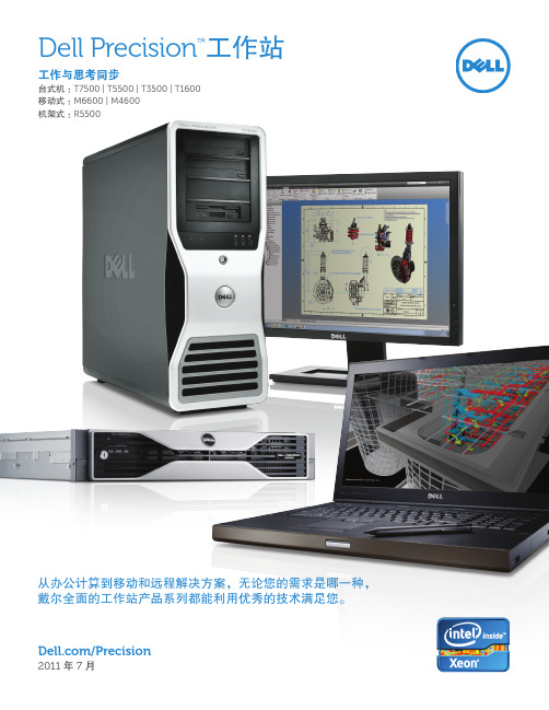
免工具机箱 对于 Dell Precision 塔式工作站,普通硬件的更换或升级非常便捷。这是因为我们的 免工具机箱能够让您快速更换硬盘、内存或扩展卡,轻松而简单。
• 专业技术支持的协作式支持功能甚至还可针对非戴尔软 硬件故障为您提供帮助。我们将利用戴尔与顶级第三方
舒适的可管理性 • 安全、可管理、易于维护的工作站,可无缝地与您的环境
供应商建立的合作关系,以单点联系人的身份帮您解决 各种难题。
相集成
• 借助戴尔 CFI 提供简化的采购和部署选项
4
Dell Precision 塔式工作站
特别适合于 :受空间限制的多线程 / 多任务工作站环境, 特别适合于 :高级分析、工程设计和设计环境 ;能够 包括财务分析、专业工程设计、数字视频和内容设计。 为一系列工作站级应用程序提供经认证的可靠性能。
特别适合于 :期望从高端台式机迁移到工作站级处理 器和显卡的专业人士 ;支持 2D 应用程序和入门级 3D 应用程序的理想之选。
机箱内的通风 (Dell Precision T7500)
至尊散热,极致安静 受益于内部安装的温度传感器,Dell Precision 工作站能够持续监控机箱内部的温度, 进而智能地控制风扇速度,最终实现了顶级水准的散热性能。戴尔采用了高级散热工 程设计和高效的处理器散热器,能够维持英特尔睿频加速模式,即使在超长工作时间 内也能如此。
Dell Precision T7500/T5500/T3500/T1600
无与伦比的性能、始终如一的可靠性、超凡脱俗的运行能力和卓尔不群的扩展能力 即使是处理最大型的数据集和最复杂的多线程应用程序,也能尽享快如闪电的性能, 更能做到节能环保 : • 最多支持两个强大的英特尔处理器,让您享受多至十二个内核的超级计算能力 • 最高 192 GB1 的先进纠错码内存 • 快如闪电的 SATA 或 SAS 存储设备 • 支持各种 RAID 选择 • 支持最多两个专业级显卡 • 部分塔式工作站支持 NVIDIA Tesla GPGPU 计算解决方案,能够实现高性能的计算
戴尔笔记本电脑快速参考指南.pdf_1700775298.7455766说明书
Dell Precision™ M90MobileWorkstation Quick Reference GuideModel PP05XAw w w.d e l l.c o m|s u p p o r t.d e l l.c o mNotes, Notices, and CautionsNOTE: A NOTE indicates important information that helps you make better use of your computer.NOTICE: A NOTICE indicates either potential damage to hardware or loss of data and tells you how to avoid theproblem.CAUTION: A CAUTION indicates a potential for property damage, personal injury, or death.Abbreviations and AcronymsFor a complete list of abbreviations and acronyms, see Glossary in your User’s Guide.If you purchased a Dell™ n Series computer, any references in this document to Microsoft® Windows®operating systems are not applicable.____________________Information in this document is subject to change without notice.© 2006Dell Inc.All rights reserved.Reproduction in any manner whatsoever without the written permission of Dell Inc.is strictly forbidden.Trademarks used in this text: Dell, the DELL logo, Dell Precision, and ExpressCharge are trademarks of Dell Inc.; Intel is a registered trademark of Intel Corporation; Microsoft and Windows are registered trademarks of Microsoft Corporation; Bluetooth is a trademark owned by Bluetooth SIG, Inc. and is used by Dell Inc. under license.Other trademarks and trade names may be used in this document to refer to either the entities claiming the marks and names or their products. Dell Inc. disclaims any proprietary interest in trademarks and trade names other than its own.Model PP05XAFebruary 2006P/N PD063Rev. A00ContentsFinding Information (5)Setting Up Your Computer (8)About Your Computer (9)Front View (9)Left Side View (10)Right Side View (10)Back View (11)Bottom View (12)Using a Battery (13)Battery Performance (13)Checking the Battery Charge (14)Charging the Battery (16)Replacing the Battery (16)Storing a Battery (17)Troubleshooting (17)Lockups and Software Problems (17)Dell Diagnostics (19)Index (23)Contents34ContentsFinding InformationNOTE: Some features or media may be optional and may not ship with your computer. Some features or media may not be available in certain countries.NOTE: Additional information may ship with your computer.What Are You Looking For?Find It Here•A diagnostic program for my computer •Drivers for my computer•My computer documentation•My device documentation •Notebook System Software (NSS)Drivers and Utilities CD (also known as ResourceCD) NOTE: The Drivers and Utilities CD may be optional and may not ship with your computer.Documentation anddrivers are alreadyinstalled on yourcomputer. Y ou can use theCD to reinstall drivers orto run the Dell Diagnostics(See "Dell Diagnostics" onpage19).Readme files may beincluded on your CD toprovide last-minute updates about technical changes to your computer or advanced technical-reference material for technicians or experienced users.NOTE: Drivers and documentation updates can be found at .•Warranty information•Terms and Conditions (U.S. only)•Safety instructions•Regulatory information•Ergonomics information•End User License AgreementDell™ Product Information Guide•How to remove and replace parts •Specifications•How to configure system settings •How to troubleshoot and solve problems Dell Precision™ User’s GuideMicrosoft Windows XP Help and Support Center1Click Start→Help and Support→Dell User and System Guides→System Guides.2Click theUser’s Guidefor your computer.Quick Reference Guide5•Service Tag and Express Service Code •Microsoft Windows License Label Service Tag and Microsoft® Windows® LicenseThese labels are located on your computer.•Use the Service Tag to identify your computer when you use or contact technical support.•Enter the Express ServiceCode to direct your callwhen contacting technicalsupport.•Solutions — Troubleshooting hints and tips, articles from technicians, and online courses, frequently asked questions•Community — Online discussion with other Dell customers•Upgrades — Upgrade information for components, such as memory, the hard drive, and the operating system •Customer Care — Contact information, service call and order status, warranty, and repair information •Service and support — Service call status and support history, service contract, online discussions with technical support•Reference — Computer documentation, details on my computer configuration, product specifications, and white papers•Downloads — Certified drivers, patches, and software updates•Notebook System Software (NSS)— If you reinstall the operating system for your computer, you should also reinstall the NSS utility. NSS provides critical updates for your operating system and support for Dell™3.5-inch USB floppy drives, Intel® processors, optical drives, and USB devices. NSS is necessary for correct operation of your Dell computer. The software automatically detects your computer and operating system and installs the updates appropriate for your configuration.Dell Support Website — NOTE: Select your region to view the appropriate support site.To download Notebook System Software:1Go to , select your region or business segment, and enter your Service Tag.2Select Drivers & Downloads and click Go.3Click your operating system and search for the keyword Notebook System Software.NOTE: The user interface may vary depending on your selections.What Are You Looking For?Find It Here6Quick Reference Guide•Software upgrades and troubleshooting hints — Frequently asked questions, hot topics, and general health of your computing environment Dell Support UtilityThe Dell Support Utility is an automated upgrade and notification system installed on your computer. This support provides real-time health scans of your computing environment, software updates, and relevant self-support information. Access the Dell Support Utility from the icon in the taskbar. For more information, see "Dell SupportUtility" in your User’s Guide.•How to use Windows XP•How to work with programs and files •How to personalize my desktop Windows Help and Support Center1Click the Start button and click Help and Support.2T ype a word or phrase that describes your problem and click the arrow icon.3Click the topic that describes your problem.4Follow the instructions on the screen.•How to reinstall my operating system Operating System CDNOTE: The Operating System CD may be optional and maynot ship with your computer.The operating system is already installed on your computer.To reinstall your operating system, use the OperatingSystem CD. See "Reinstalling Windows XP" in your User’sGuide.After you reinstall youroperating system, use theDrivers and Utilities CD(ResourceCD) to reinstalldrivers for the devices thatcame with your computer.Y our operating systemproduct key label is locatedon your computer.NOTE: The color of your CD varies based on the operatingsystem you ordered.What Are You Looking For?Find It HereQuick Reference Guide78Quick Reference GuideSetting Up Your ComputerCAUTION: Before you begin any of the procedures in this section, follow the safety instructions in theProduct Information Guide .1Unpack the accessories box.2Set aside the contents of the accessories box, which you will need to complete the setup of your computer.The accessories box also contains user documentation and any software or additional hardware (such as PC Cards, drives, or batteries) that you have ordered.3Connect the AC adapter to the AC adapter connector on the computer and to the electrical outlet.4Open the computer display and press the power button to turn on the computer (see "Front View" on page 9).NOTE: It is recommended that you turn on and shut down your computer at least once before you install any cards or connect the computer to a docking device or other external device, such as a printer.Quick Reference Guide 9About Your ComputerFront View1display latches (2)6touch pad11keyboard 2display latch release 7media control buttons 12media button 3display 8speakers (2)13keyboard and wireless status lights4power button 9touch pad buttons 5device status lights10touch-pad scroll zone2113694813571121010Quick Reference GuideLeft Side ViewRight Side View1security cable slot 3USB connectors (2)5optical-drive-tray eject button2air vent4optical drive1smart card slot 4IEEE 1394 connector 7air vent2hard drive 55-in-1 media memory card reader3ExpressCard slot6audio connectors (2)123452345671Back View1air vent 5USB connectors (2)9AC adapter connector 2S-video TV-out connector 6USB connectors (2)10air vent3network (RJ-45) connector 7Digital-Video Interface(DVI) connector4modem (RJ-11) connector 8video (VGA) connector 12345678910Bottom View1subwoofer 5cover for optional internalcard with Bluetooth ®wireless technology9docking-device connector 2battery charge/health gauge 6hard drive10memory module cover 3battery-bay latch release 7air vent11air vent 4battery 8Mini-Card/modem cover12optical-drive security screw123456789111210Using a BatteryBattery PerformanceNOTE: For information about the Dell warranty for your computer, see the Product Information Guide or separate paper warranty document that shipped with your computer.For optimal computer performance and to help preserve BIOS settings, operate your Dell™ portable computer with the battery installed at all times. One battery is supplied as standard equipment in the battery bay.NOTE: Because the battery may not be fully charged, use the AC adapter to connect your new computer to an electrical outlet the first time you use the computer. For best results, operate the computer with the AC adapter until the battery is fully charged. To view battery charge status, click Start→ Control Panel→ Power Options, and click Power Meter tab.NOTE: Battery operating time (the time the battery can operate the computer) decreases over time. Depending on how often the battery is used and the conditions under which it is used, you may need to purchase a new battery during the life of your computer.Battery operating time varies depending on operating conditions. Operating time is significantly reduced when you perform operations including, but not limited to, the following:•Using optical drives.•Using wireless communications devices, ExpressCards, or USB devices.•Using high-brightness display settings, 3D screen savers, or other power-intensive programs such as complex 3D graphics applications.•Running the computer in maximum performance mode. See "Configuring Power Management Settings" on in your User’s Guide for information about accessing Windows Power Options Properties or Dell QuickSet, which you can use to configure power management settings.NOTE: It is recommended that you connect your computer to an electrical outlet when writing to a CD or DVD.Y ou can check the battery charge before you insert the battery into the computer. Y ou can also set power management options to alert you when the battery charge is low. For more information, see "Checking the Battery Charge" on page14.CAUTION: Using an incompatible battery may increase the risk of fire or explosion. Replace the battery only with a compatible battery purchased from Dell. The battery is designed to work with your Dell computer. Do not use a battery from other computers with your computer.CAUTION: Do not dispose of batteries with household waste. When your battery no longer holds a charge, call your local waste disposal or environmental agency for advice on disposing of a lithium-ion battery. See "Battery Disposal" in the Product Information Guide.CAUTION: Misuse of the battery may increase the risk of fire or chemical burn. Do not puncture, incinerate, disassemble, or expose the battery to temperatures above 65°C (149°F). Keep the battery away from children.Handle damaged or leaking batteries with extreme care. Damaged batteries may leak and cause personal injury or equipment damage.Checking the Battery ChargeThe Dell QuickSet Battery Meter, the Microsoft Windows Power Meter window and icon, the battery charge gauge and health gauge, and the low-battery warning provide information on the battery charge.NOTE: Dell QuickSet may not be available on your computer.Dell™ QuickSet Battery MeterIf Dell QuickSet is installed, press <Fn><F3> to display the QuickSet Battery Meter. The Battery Meter displays status, battery health, charge level, and charge completion time for the battery in your computer. For more information about QuickSet, right-click the icon in the taskbar, and click Help.Microsoft® Windows® Power MeterThe Windows Power Meter indicates the remaining battery charge. To check the Power Meter, double-click the icon on the taskbar.If the computer is connected to an electrical outlet, a icon appears.Charge GaugeBy pressing (or pressing and holding) the status button on the charge gauge on the battery, you can check:•Battery charge (check by pressing and releasing the status button)•Battery health (check by pressing and holding the status button)The battery operating time is largely determined by the number of times it is charged. After hundreds of charge and discharge cycles, batteries lose some charge capacity—or battery health. That is, a battery can show a status of "charged" but maintain a reduced charge capacity (health).Check the Battery ChargeTo check the battery charge, press the status button on the battery charge gauge to illuminate the charge-level lights. Each light represents approximately 20 percent of the total battery charge. For example, if the battery has 80 percent of its charge remaining, four of the lights are on. If no lights appear, the battery has no charge.Check the Battery HealthNOTE: You can check battery health either by using the charge gauge on the battery as described below, or by using the Battery Meter in Dell QuickSet. For information about QuickSet, right-click the icon in the taskbar, and click Help.To check the battery health using the charge gauge, press and hold the status button on the battery charge gauge for at least 3seconds. If no lights appear, the battery is in good condition, and more than 80percent of its original charge capacity remains. Each light represents incremental degradation. If five lights appear, less than 60percent of the charge capacity remains, and you should consider replacing the battery. See "Specifications" in your User’s Guide for more information about the battery operating time.Low-Battery WarningNOTICE: To avoid losing or corrupting data, save your work immediately after a low-battery warning.Then connect the computer to an electrical outlet. If the battery runs completely out of power, hibernate mode begins automatically.A pop-up window warns you when the battery charge is approximately 90 percent depleted. The computer enters hibernate mode when the battery charge is at a critically low level.Y ou can change the settings for the battery alarms in QuickSet or the Power Options Properties window. See "Configuring Power Management Settings" in your User’s Guide for information about accessing QuickSet or the Power Options Properties window.Conserving Battery PowerPerform the following actions to conserve battery power:•Connect the computer to an electrical outlet when possible because battery life is largely determined by the number of times the battery is used and recharged.•Place the computer in standby mode or hibernate mode when you leave the computer unattended for long periods of time. See "Power Management Modes" in your User’s Guide for more information about standby and hibernate modes.•Use the Power Management Wizard to select options to optimize your computer’s power usage. These options can also be set to change when you press the power button, close the display, or press<Fn><Esc>. See "Configuring Power Management Settings" in your User’s Guide for moreinformation on using the Power Management Wizard.NOTE: See "Configuring Power Management Settings" in your User’s Guide.Charging the BatteryNOTE: With Dell™ ExpressCharge™, when the computer is turned off, the AC adapter charges a completely discharged battery to 80 percent in about 1 hour and to 100 percent in approximately 2 hours. Charge time is longer with the computer turned on. You can leave the battery in the computer for as long as you like. The battery’s internal circuitry prevents the battery from overcharging.When you connect the computer to an electrical outlet or install a battery while the computer is connected to an electrical outlet, the computer checks the battery charge and temperature. If necessary, the AC adapter then charges the battery and maintains the battery charge.If the battery is hot from being used in your computer or being in a hot environment, the battery may not charge when you connect the computer to an electrical outlet.The battery is too hot to start charging if the light flashes alternately orange and green. Disconnect the computer from the electrical outlet and allow the computer and the battery to cool to room temperature. Then connect the computer to an electrical outlet to continue charging the battery.For more information about resolving problems with a battery, see "Power Problems" in your User’s Guide. Replacing the BatteryCAUTION: Before performing these procedures, turn off the computer, disconnect the AC adapter from the electrical outlet and the computer, disconnect the modem from the wall connector and computer, and remove any other external cables from the computer.NOTICE: You must remove all external cables from the computer to avoid possible connector damage.CAUTION: Using an incompatible battery may increase the risk of fire or explosion. Replace the battery only with a compatible battery purchased from Dell. The battery is designed to work with your Dell™ computer. Do not use a battery from other computers with your computer.To remove the battery:1If the computer is connected to a docking device (docked), undock it. See the documentation that came with your docking device for instructions.2Ensure that the computer is turned off.3Slide and hold the battery-bay latch release on the bottom of the computer, and then lift the battery from the bay.To replace the battery, follow the removal procedure in reverse order.Storing a BatteryRemove the battery when you store your computer for an extended period of time. A battery discharges during prolonged storage. After a long storage period, recharge the battery fully before you use it. See "Charging the Battery" on page 16.TroubleshootingLockups and Software Problems CAUTION: Before you begin any of the procedures in this section, follow the safety instructions in theProduct Information Guide .The computer does not start upE N S U R E T H A T T H E AC A D A P T E R I SF I R M L Y C O N N E C T E D T O T H E C O M P U T E R A N D T O T H E E L E C T R I C A L O U T L E T The computer stops respondingNOTICE: You might lose data if you are unable to perform an operating system shutdown.T U R N T H E C O M P U T E R O F F —If you are unable to get a response by pressing a key on your keyboard or moving your mouse, press and hold the power button for at least 8 to 10 seconds until the computer turns off. Then restart your computer.1battery-bay latch release 2battery12A program stops responding or crashes repeatedlyNOTE: Software usually includes installation instructions in its documentation or on a floppy disk or CD.E N D T H E P R O G R A M—1Press <Ctrl><Shift><Esc> simultaneously.2Click Task Manager.3Click the program that is no longer responding.4Click End Task.C H E C K T H E S O F T W A R ED O C U ME N T A T I O N—If necessary, uninstall and then reinstall the program.A program is designed for an earlier Microsoft® Windows® operating systemR U N T H E P R O G R A M C O M P A T I B I L I T Y W I Z A R D—The Program Compatibility Wizard configures a program so it runs in an environment similar to non-Windows XP operating system environments.1Click the Start button, point to All Programs→Accessories, and then click Program Compatibility Wizard.2In the welcome screen, click Next.3Follow the instructions on the screen.A solid blue screen appearsT U R N T H E C O M P U T E R O F F—If you are unable to get a response by pressing a key on your keyboard or moving your mouse, press and hold the power button for at least 8 to 10 seconds until the computer turns off. Then restart your computer.Other software problemsC H E C K T H E S O F T W A R ED O C U ME N T A T I O N O R C O N T A C T T H E S OF T W A R E M A N U F A C T U R E R F O R T R O U B L E S H O O T I NG I N F O R M A T I O N—•Ensure that the program is compatible with the operating system installed on your computer.•Ensure that your computer meets the minimum hardware requirements needed to run the software.See the software documentation for information.•Ensure that the program is installed and configured properly.•Verify that the device drivers do not conflict with the program.•If necessary, uninstall and then reinstall the program.B AC K U P Y O U R F I L E S I M M ED I A TE L YU S E A V I R U S-S C A N N I N G P R O G R A M T O C H E C K T H E H A R D D R I V E, F L O P P Y D I S K S, O R CD SS A V E A N D C L O S E A N Y O P E N F I L E S O R P R O G R A M S A N D S H U T D O W N Y O U R C O M P U T E R T H R O U G H T H E Start M E N U S C A N T H E C O M P U T E R F O R S P Y W A R E—If you are experiencing slow computer performance, you frequently receive pop-up advertisements, or you are having problems connecting to the Internet, your computer might be infected with spyware. Use an anti-virus program that includes anti-spyware protection (your program may require an upgrade) to scan the computer and remove spyware. For more information, go to and search for the keyword spyware.R U N T H E D E L L D I A G N O S T I C S—See "Dell Diagnostics" on page19. If all tests run successfully, the error condition is related to a software problem.Dell DiagnosticsCAUTION: Before you begin any of the procedures in this section, follow the safety instructions in the Product Information Guide.When to Use the Dell DiagnosticsIf you experience a problem with your computer, perform the checks in "Lockups and Software Problems" on page17 and run the Dell Diagnostics before you contact Dell for technical assistance.It is recommended that you print these procedures before you begin.NOTICE: The Dell Diagnostics works only on Dell computers.NOTE: The Drivers and Utilities CD is optional and may not ship with your computer.Enter system setup, review your computer’s configuration information, and ensure that the device you want to test displays in system setup and is active.Start the Dell Diagnostics from either your hard drive or from the Drivers and Utilities CD (also known as the ResourceCD).Starting the Dell Diagnostics From Your Hard Drive1T urn on (or restart) your computer.a When the DELL™ logo appears, press <F12> immediately. Select Diagnostics from the bootmenu and press <Enter>.NOTE: If you wait too long and the operating system logo appears, continue to wait until you see theMicrosoft® Windows® desktop. Then shut down your computer and try again.b Press and hold the <Fn> key while powering the system on.NOTE: If you see a message stating that no diagnostics utility partition has been found, run the DellDiagnostics from the Drivers and Utilities CD.2See "Contacting Dell" in your User’s Guide.Starting the Dell Diagnostics From the Drivers and Utilities CD1Insert the Drivers and Utilities CD.2Shut down and restart the computer.When the DELL logo appears, press <F12> immediately.If you wait too long and the Windows logo appears, continue to wait until you see the Windows desktop. Then shut down your computer and try again.NOTE: The next steps change the boot sequence for one time only. On the next start-up, the computer bootsaccording to the devices specified in the system setup program.3When the boot device list appears, highlight CD/DVD/CD-RW Drive and press <Enter>.4Select the Boot from CD-ROM option from the menu that appears and press <Enter>.5T ype 1 to start the ResourceCD menu and press <Enter> to proceed.6Select Run the 32 Bit Dell Diagnostics from the numbered list. If multiple versions are listed, select the version appropriate for your computer.7When the Dell Diagnostics Main Menu appears, select the test you want to run.Dell Diagnostics Main Menu1After the Dell Diagnostics loads and the Main Menu screen appears, click the button for the option you want.2If a problem is encountered during a test, a message appears with an error code and a description of the problem. Write down the error code and problem description and follow the instructions on the screen.If you cannot resolve the error condition, contact Dell. See "Contacting Dell" in your User’s Guide .NOTE: The Service Tag for your computer is located at the top of each test screen. If you contact Dell,technical support will ask for your Service Tag.OptionFunction Express Test Performs a quick test of devices. This test typically takes 10 to20minutes and requires no interaction on your part. Run Express Testfirst to increase the possibility of tracing the problem quickly.Extended Test Performs a thorough check of devices. This test typically takes 1 hour ormore and requires you to answer questions periodically.Custom Test Tests a specific device. Y ou can customize the tests you want to run.Symptom T reeLists the most common symptoms encountered and allows you to selecta test based on the symptom of the problem you are having.Quick Reference Guide 213If you run a test from the Custom Test or Symptom Tree option, click the applicable tab described in the following table for more information.4When the tests are completed, if you are running the Dell Diagnostics from the Drivers and Utilities CD , remove the CD.5Close the test screen to return to the Main Menu screen. To exit the Dell Diagnostics and restart the computer, close the Main Menu screen.Tab FunctionResults Displays the results of the test and any error conditions encountered.Errors Displays error conditions encountered, error codes, and the problem description.Help Describes the test and may indicate requirements for running the test.ConfigurationDisplays your hardware configuration for the selected device.The Dell Diagnostics obtains configuration information for all devices from the system setup program, memory, and various internal tests, and it displays the information in the device list in the left pane of the screen. The device list may not display the names of all thecomponents installed on your computer or all devices attached to your computer.ParametersAllows you to customize the test by changing the test settings.。
09年3月份日照九州戴尔笔记本标准配置及价格表doc-4

37%
9,893.
27
笔记本
戴尔E6400 (14寸)
主板Intel(R) 45 Express芯片组/ CPU Intel酷睿2 P8400, 2.26GHz, 1066MHz, 3MB)/ 14.1" LED WXGA+ (1440X900) TrueLife(TM) / 2GB内存(1x2G) DR2 800MHz / 64G SSD固态硬盘2.5" / DVD刻录光驱/ 256MB独立显卡NVS 160M / Dell Wireless(TM) 1510无线网卡(802.11a/b/g/n 2X3)/ Windows vista Home SP1正版操作系统/指纹识别器/蓝牙/内置摄像头/背光键盘/原厂笔记本包和光电鼠标/ 6芯电池/ 65W电源适配器/内置调制解调器/黑色本
16231
43%
.9252
22
笔记本
戴尔E5400 (14寸)
主板Intel(R) 45 Express芯片组/ CPU Intel酷睿2P8600(2.40GHz 1066MHz 3M)/ 14.1"(1440 x 900)/2GB内存(1x2G) DR2 800MHz /250GSATA硬盘7200 RPM/ DVD刻录光驱/集成显卡/ Dell Wireless(TM) 1510无线网卡(802.11a/b/g/n 2X3)/双指点杆/蓝牙/原厂笔记本包和光电鼠标/ 6芯电池笔记本电池的质量保证期为一年/ /三年上门保修65W电源适配器/内置调制解调器/黑色笔记本
5699
8%
5300
4
笔记本
戴尔1330(13寸)
T6400/ 2G/250G / 128M 8400GS显卡/ 13.3”/ DVDRW/ 6蕊电池/无线/200万摄像头黑色笔记本
戴尔笔记本电脑说明书.pdf_1701115644.4817057
正面视图左侧视图右侧视图背面视图底部视图1 显示屏7 扬声器(2)2 电源按钮8 定点杆/触摸板按钮3 设备状态指示灯9 定点杆4 键盘10 音量控制按钮5 触摸板11 静音按钮6 显示屏闩锁12 键盘和无线状态指示灯在计算机打开时亮起,在计算机处于电源管理模式时闪烁。
在计算机读取或写入数据时亮起。
注意:为避免数据丢失,切勿在 指示灯闪烁时关闭计算机电源。
如果计算机已连接至电源插座,则 指示灯的状态包括:如果计算机使用电池电量运行,则 指示灯的状态包括:键盘上方的绿色指示灯表示以下信息:启用数字小键盘时亮起。
启用无线设备时亮起。
启用大写字母功能时亮起。
蓝牙无线技术是计算机上的可选功能,因此仅当您随计算机一起订购了蓝牙无线技术,系统才会显示 图标。
有关详情,请参阅蓝牙无线技术附带的说明文件。
1 安全缆线孔 4 PC 卡插槽2 音频连接器(2) 5 智能卡插槽3 红外线传感器注:计算机在变热时会打开风扇。
风扇噪音是正常现象,并不表示风扇或计算机有问题。
连接器用于连接耳机或扬声器。
连接器用于连接麦克风。
右侧视图1 网络连接器 (RJ-45) 6 串行连接器视频连接器交流适配器将交流电源转换为计算机所需的直流电源。
无论计算机处于打开或关闭状态,您均可以连接交流适配器。
警告:此交流适配器可以与世界各地的电源插座配合使用。
但是,电源连接器和配电电盘或电源插座可能会引起火灾或损坏设备。
注意:从计算机上断开交流适配器电缆的连接时,请握住连接器(而不是电缆本身),并稳而轻地将其拔出,以免损坏电缆。
1 内存模块护盖 5 对接设备插槽2 电池槽释放闩锁 6 风扇3 电池电量表7 小型 PCI 卡/调制解调器护盖4 电池8 硬盘驱动器内存模块护盖—用于保护安装内存模块的凹槽。
请参阅“添加和更换部件返回目录页面附录Dell Precision™ M20 移动工作站用户指南Macrovision 产品通告Macrovision 产品通告本产品采用了版权保护技术,它通过申请属于 Macrovision Corporation 和其他产权所有者的美国专利权以及其它知识产权来进行保护。
Dell Dimension 1100 B110 用户手册说明书
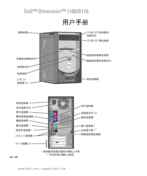
w w w.d e l l.c o m | s u p p o r t.d e l l.c o mDell™ Dimension™ 1100/B110用户手册型号:DMC**并非所有计算机上都有。
键盘连接器USB 2.0 *输出连接器串行连接器PCI 卡插槽电源连接器 (4)***具有集成音频功能的计算机上才有。
或 DVD 驱动器活或 DVD 弹出按钮连接器注、注意和警告注:注表示可以帮助您更好地使用计算机的重要信息。
注意:注意表示可能会损坏硬件或导致数据丢失,并告诉您如何避免此类问题。
警告:警告表示可能会导致财产损失、人身伤害甚至死亡。
如果您购买的是 Dell™ n Series 计算机,则本说明文件中有关 Microsoft® Windows®操作系统的所有参考信息均不适用。
____________________本说明文件中的信息如有更改,恕不另行通知。
©2006Dell Inc.。
版权所有,翻印必究。
未经 Dell Inc. 书面许可,严禁以任何形式进行复制。
本文中使用的商标:Dell、DELL徽标、Inspiron、Dell Precision、Dimension、OptiPlex、Latitude、PowerEdge、PowerVault、PowerApp、PowerConnect和Dell OpenManage是 Dell Inc. 的商标;Intel、Pentium和Celeron是 Intel Corporation 的注册商标;Microsoft、Windows和Outlook是 Microsoft Corporation 的注册商标。
本说明文件中述及的其它商标和产品名称是指拥有相应商标和产品名称的公司或其制造的产品。
Dell Inc. 对其它公司的商标和产品名称不拥有任何所有权。
型号:DMC2006 年 9 月P/N UD577修订版 A04目录查找信息 (7)1设置和使用计算机设置打印机 (9)打印机电缆 (9)连接 USB 打印机 (9)连接并行打印机 (10)设置家庭和办公网络 (11)连接网络适配器 (11)网络安装向导 (12)连接至 Internet (12)设置 Internet 连接 (13)播放 CD 和 DVD (14)调节音量 (15)调整图片 (16)复制 CD 和 DVD (16)如何复制 CD 或 DVD (16)使用空白 CD 和 DVD (17)注意事项 (18)超线程 (18)2解决问题故障排除提示 (19)电池问题 (19)驱动器问题 (19)CD 和 DVD 驱动器问题 (20)硬盘驱动器问题 (21)电子邮件、调制解调器和 Internet 问题 (21)目录3错误信息 (22)IEEE 1394 设备问题 (23)键盘问题 (24)锁定和软件问题 (24)计算机无法启动 (24)计算机停止响应 (24)程序停止响应 (25)程序多次崩溃 (25)程序设计为用于早期版本的 Windows 操作系统 (25)出现蓝屏 (25)其它软件问题 (25)内存问题 (26)鼠标问题 (26)网络问题 (27)电源问题 (28)打印机问题 (28)扫描仪问题 (29)声音和扬声器问题 (30)扬声器没有声音 (30)耳机没有声音 (31)视频和显示器问题 (31)如果屏幕为黑屏 (31)如果屏幕显示不清楚 (32)3高级故障排除诊断指示灯 (33)Dell 诊断程序 (36)Dell 诊断程序主菜单 (36)驱动程序 (37)什么是驱动程序? (37)识别驱动程序 (37)重新安装驱动程序 (38)4目录还原操作系统 (39)使用 Microsoft Windows XP 系统还原 (39)使用 Symantec 提供的 Dell PC Restore (40)使用操作系统 CD (42)解决软件与硬件不兼容的问题 (43)4卸下和安装部件开始之前 (45)建议工具 (45)关闭计算机电源 (45)拆装计算机内部组件之前 (46)计算机的正面视图和背面视图 (47)正面视图 (47)背面视图 (48)卸下主机盖 (50)计算机内部视图 (51)系统板组件 (52)内存 (53)DDR 内存概览 (53)内存安装原则 (53)安装内存 (54)插卡 (56)PCI 卡 (56)前面板 (59)卸下前面板 (59)卸下前面板插件 (60)重新连接前面板 (60)驱动器 (61)一般安装原则 (62)连接驱动器电缆 (62)硬盘驱动器 (63)卸下硬盘驱动器 (63)安装硬盘驱动器 (65)目录5软盘驱动器 (67)卸下软盘驱动器 (67)安装软盘驱动器 (68)CD/DVD 驱动器 (70)卸下 CD/DVD 驱动器 (70)安装 CD/DVD 驱动器 (71)添加第二个 CD 或 DVD 驱动器 (72)电池 (73)装回主机盖 (74)5附录规格 (77)系统设置程序 (80)概览 (80)进入系统设置程序 (80)系统设置程序选项 (82)引导顺序 (86)清除已忘记的密码 (88)清洁计算机 (89)计算机、键盘和显示器 (89)鼠标 (89)软盘驱动器 (89)CD 和 DVD (89)与 Dell 联络 (90)索引 (109)6目录查找信息7查找信息注: 并非所有功能或介质都是必需的,您的计算机可能未附带某些功能或介质。
台式电脑选型表(DELL1)
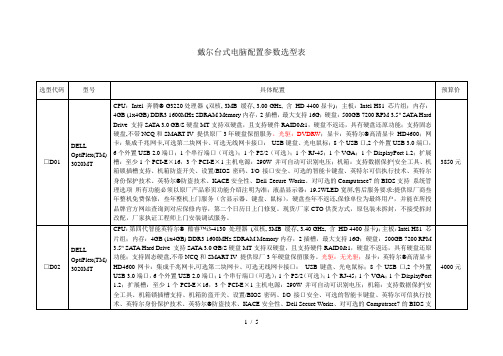
□D06
DELLOptiPlex(TM)7010MT
CPU:智能英特尔®酷睿™ i5-3470处理器(6M缓存, 3.20 GHz);主板:Intel Q77芯片组支持第三代i系列处理器;内存:4G DDR3 1600MHz SDRAM内存,四个内存插槽,最大支持16G;硬盘:500G SATA,MT支持双硬盘,且支持硬件RAID0&1,硬盘不返还,具有硬盘还原功能;支持固态硬盘。光驱:无光驱;显卡:英特尔®高清显卡4000;网卡:集成千兆网卡,可选第二块网卡、可选无线网卡接口:USB键盘、光电鼠标;12个USB(4个USB3.0接口, 8个USB 2.0端口,4前置, 6后置,2内置),2组音频接口(1组前置1组后置),2个PS/2端口,1个VGA,2个DisplayPort,1个串口,可选1394a PCI卡;扩展槽:至少2个PCI-E×16,1个PCI-E×1,1个PCI主机电源:275W并可自动可识别电压;机箱:塔式,电源按键的颜色来判断故障;高效散热静音,带有安全锁孔,机箱开合感应开关,整机防盗线缆锁设计,免工具开箱和部件维护,硬盘无螺钉设计,带硬盘防震托架,扩展卡无螺钉设计,光驱无螺钉设计;内置音频扬声器;液晶显示器:19.5LED宽屏;售后服务要求:提供原厂商叁年整机免费保修,叁年整机上门服务(含显示器、键盘、鼠标),硬盘叁年不返还,保修单位为最终用户,并能在所投品牌官方网站查询到对应保修内容,第二个日历日上门修复。现货/厂家CTO供货方式,原包装未拆封,不接受拆封改配,厂家执证工程师上门安装调试服务。
4000元
□D03
DELLOptiPlex(TM) 3020MT
CPU:第四代智能英特尔®酷睿™i3-4130处理器(双核, 3MB缓存, 3.40 GHz,含HD 4400显卡);主板:Intel H81芯片组;内存:4GB (1x4GB) DDR3 1600MHz SDRAM Memory内存,2插槽,最大支持16G;硬盘:500GB 7200 RPM 3.5" SATA Hard Drive支持SATA 3.0 GB/S硬盘MT支持双硬盘,且支持硬件RAID0&1,硬盘不返还,具有硬盘还原功能;支持固态硬盘,不带NCQ和SMART IV提供原厂3年硬盘保留服务。光驱:无光驱;显卡:AMD Radeon™ HD 8490, 1GB独显;网卡:集成千兆网卡,可选第二块网卡、可选无线网卡接口:USB键盘、光电鼠标;8个USB口,2个外置USB 3.0端口,6个外置USB 2.0端口;1个串行端口(可选);1个PS/2(可选);1个RJ-45;1个VGA;1个DisplayPort 1.2;扩展槽:至少1个PCI-E×16,3个PCI-E×1主机电源:290W并可自动可识别电压;机箱:支持数据保护|安全工具、机箱锁插槽支持、机箱防盗开关、设置/BIOS密码、I/O接口安全、可选的智能卡键盘、英特尔可信执行技术、英特尔身份保护技术、英特尔®防盗技术、KACE安全性、Dell Secure Works、对可选的Computrace7的BIOS支持系统管理选项所有功能必须以原厂产品彩页功能介绍注明为准;液晶显示器:19.5WLED宽屏;售后服务要求:提供原厂商叁年整机免费保修,叁年整机上门服务(含显示器、键盘、鼠标),硬盘叁年不返还,保修单位为最终用户,并能在所投品牌官方网站查询到对应保修内容,第二个日历日上门修复。现货/厂家CTO供货方式,原包装未拆封,不接受拆封改配,厂家执证工程师上门安装调试LOptiPlex(TM) 3020MT
戴尔易安信系统更新版本 1.9.2.0 安全配置指南说明书
Dell EMC System Update version 1.9.2.0 Security Configuration GuideNotes, cautions, and warningsA NOTE indicates important information that helps you make better use of your product.A CAUTION indicates either potential damage to hardware or loss of data and tells you how to avoidA WARNING indicates a potential for property damage, personal injury, or death.© 2021 Dell Inc. or its subsidiaries. All rights reserved. Dell, EMC, and other trademarks are trademarks of Dell Inc. or its subsidiaries. Other trademarks may be trademarks of their respective owners.Figures (4)Tables (5)Chapter 1: PREFACE (6)Terms used in this document (7)Chapter 2: Deployment models (8)Security profiles (8)Chapter 3: Product and Subsystem Security (9)Security controls map (9)Authentication (9)Access control (9)Login security settings (10)Failed login behavior (10)Remote connection security (10)User and credential management (10)Network security (10)Network exposure (10)Outbound ports (10)Inbound ports (11)Data security (11)Auditing and logging (11)Serviceability (11)Product code integrity (12)Chapter 4: Miscellaneous Configuration and Management (13)Dell EMC System Update licensing (13)Protect authenticity and integrity (13)Manage backup and restore in Dell EMC System Update (13)Contents31Security Controls Map (9)4Figures1Revision History (6)2Terms used in this document (7)3Outbound ports (10)4Inbound ports (11)Tables51PREFACE As part of an effort to improve its product lines, Dell EMC periodically releases revisions of its software and hardware. Some functions that are described in this document might not be supported by all versions of the software or hardware currently in use. The product release notes provide the most up-to-date information about product features.Contact your Dell EMC technical support professional if a product does not function properly or does not function as described in this document. This document was accurate at publication time. To ensure that you are using the latest version of this document, go to https:///support.Legacy disclaimersThe information in the publication is provided as-is. Dell Technologies makes no representations or warrantiesof any kind regarding the information in the publication, and specifically disclaims implied warranties of merchantability or fitness for a particular purpose. In no event shall Dell Technologies, its affiliates or suppliers, be liablefor any damages whatsoever arising from or related to the information contained herein or actions that you decide to take based thereon, including any direct, indirect, incidental, consequential, loss of business profits or special damages, even if Dell Technologies, its affiliates or suppliers have been advised of the possibility of such damages.The Security Configuration Guide intends to be a reference. The guidance is provided based on a diverse set of installed systems and may not represent the actual risk/guidance to your local installation and individual environment. It is recommended that all users determine the applicability of this information to their individual environments and take appropriate actions. All aspects of this Security Configuration Guide are subject to change without notice and on a case-by-case basis. Your use of the information that is contained in this document or materials that are linked herein is at your own risk. Dell reserves the right to change or update this document in its sole discretion and without notice at any time.Scope of the documentThis document includes information about security features and capabilities of Dell EMC System Update (DSU). AudienceThis document is intended for individuals who are responsible for managing security for Dell EMC System Update. Revision HistoryThe following table presents the revision history of this document.Table 1. Revision HistoryRevision Date DescriptionA00July 2021Initial release of the Dell EMCSystem Update 1.9.2.0 Security GuidelineDocument.A00March 2021Initial release of the Dell EMCSystem Update 1.9.1.0 Security GuidelineDocument.6PREFACEDocument ReferencesIn addition to this guide, you can access the other guides available at /support . Since DSU supports an Update to the Server through iDRAC, see Integrated Dell Remote Access Controller User's Guide for any configuration-related queries. For the information about supported PowerEdge Servers, see Dell EMC Systems Management - OpenManage Software Support Matrix. Go to support site, click product support -> Dell EMC system Update to access the following documents:●Dell EMC System Update Version 1.9 User's Guide●Dell System Update 1.9 Release NotesYou can find the technical artifacts including white papers at /supportSecurity resources●Dell Security Advisories (DSA) /support/security●Support knowledge base (KB) articles at /support/kbdoc/en-us/000130590/dell-emc-system-update-dsu Getting helpContact your Dell EMC technical support professional if a product does not function properly or does not function as described in this document. This document was accurate at publication time. To ensure that you are using the latest version of this document, go to /supportReporting security vulnerabilitiesDell EMC takes reports of potential security vulnerabilities in our products very seriously. If you discover a security vulnerability, you are encouraged to report it to Dell EMC immediately. For the latest on how to report a security issue to Dell, please see the Dell Vulnerability Response Policy on the site.Topics:•Terms used in this documentTerms used in this documentTable 2. Terms used in this documentTerminology DescriptionDSU Dell EMC System UpdateDUP Dell EMC Update PackageiDRAC Integrated Dell Remote Access ControllerWMI Windows Management InstrumentationSSH Secure ShellPREFACE7Deployment models You can deploy Dell EMC System Update on Microsoft Windows Server or Linux operating system through Dell Update Package (DUP) on supported Dell EMC PowerEdge servers. Dell EMC System Update supports online or offline method to deploy on the selected operating system through Dell Update Package. For more information on the deployment of Dell System Update, see Dell EMC System Update User's Guide at /supportTopics:•Security profilesSecurity profilesDell EMC System Update has a default security profile for secure HTTP or HTTPS access with self-signed certificate during installations. It is recommended to replace the Certificate Authority (CA) signed certificates for a better security environment. 8Deployment modelsProduct and Subsystem Security Topics:•Security controls map•Authentication•Login security settings•User and credential management•Network security•Data security•Auditing and logging•Serviceability•Product code integritySecurity controls mapDell EMC System Update is a script optimized update deployment tool that is used to apply Dell EMC updates such as applications, firmware, and drivers for Linux and Microsoft Windows operating systems. Using DSU, identifies the available updates, select the relevant updates, and deploy the updates on a single system or multiple systems through operating systems or integrated Dell Remote Access Controller(iDRAC) or iDRAC passthrough(connection to the iDRAC through redfish API to get relevant firmware update and deploy. System Credentials (share location credentials) used for repository or system (remote server) access are not stored within DSU.The following figure displays the DSU security controls map:Figure 1. Security Controls MapAuthenticationAccess controlDell EMC System Update allows only administrator console and root privilege console account to perform the operation.Product and Subsystem Security9Login security settingsFailed login behaviorDellEMC System Update (DSU) populate failed login message on console for wrong credential. For more information about failed login behavior of DSU, see the Dell EMC System Update User's Guide at /supportRemote connection securityDell EMC System Update uses open source library for remote connection using SSH and WMI and it does not log the credentials mentioned for connections.User and credential managementDell EMC System Update supports HTTPS and HTTP connections.Network securityDell System Update uses a pre-configured firewall to enhance security by restricting inbound and outbound network traffic to the TCP and UDP ports. The tables in this section lists the inbound and outbound ports that Dell System Update uses. Network exposureDell System Update uses inbound and outbound ports when communicating with remote systems.Outbound portsOutbound ports can be used by Dell System Update when connecting to a remote system..The ports that are listed in the following table are the Dell System Update outbound ports.Table 3. Outbound portsPort number Layer 4 Protocol Service7TCP, UDP ECHO22TCP SSH25TCP SMTP53UDP, TCP DNS67,68TCP DHCP80TCP HTTP88TCP, UDP Kerberos111TCP, UDP ONC RPC123TCP, UDP NTP161-163TCP, UDP SNMP389TCP, UDP LDAP443TCP HTTPS10Product and Subsystem SecurityTable 3. Outbound ports (continued)Port number Layer 4 Protocol Service448TCP Data Protection Search Admin REST API 464TCP, UDP Kerberos514TCP, UDP rsh587TCP SMTP636TCP, UDP LDAPS902TCP VMware ESXi2049TCP, UDP NFS2052TCP, UDP mountd, clearvisn3009TCP Data Domain REST APIInbound portsThe inbound ports that are available to be used by a remote system when connecting to Dell System Update remote.The ports that are listed in the following table are the Dell System Update inbound ports.Table 4. Inbound portsPort number Layer 4 Protocol Service22TCP SSH80TCP HTTP443TCP HTTPS135TCP WMIData securityDSU does not store any data in databases also from input dependencies libraries. DSU uses certificates for secure HTTP access (HTTPS). By default, DSU installs GPG keys and uses the self-signed certificate for the HTTPS secure transactions. For better security, it is recommended to use the Certificate Authority (CA) signed or custom certificates.Auditing and loggingDSU administration console generate all the relevant logs in default location or user provided location. DSU supports Log file retention , compression and file rollover. Log file sizes are defined to 5 MB limit. A descriptive and clear log messages are provided. For more information about Troubleshooting, Log files, see the Dell EMC System Update User's Guide available at /supportServiceabilityThe support website https:///support provides access to licensing information, product documentation, advisories, downloads, and troubleshooting information. This information helps you to resolve a product issue before you contact support team.Special login is not required to Dell EMC System Update for service personnel. If the troubleshooting bundle is not sufficient, the personnel can enable the root user to collect more information.Ensure that you install security patches and other updates when they are available, including the Dell EMC System Update.Product and Subsystem Security11Product code integrityThe Dell EMC System Update software installer is signed by Dell. It is recommended that you verify the authenticity of the Dell EMC System Update installer signature.12Product and Subsystem Security4Miscellaneous Configuration andManagement Topics:•Dell EMC System Update licensing•Protect authenticity and integrity•Manage backup and restore in Dell EMC System UpdateDell EMC System Update licensingDSU has open source approvals for the internal dependencies and gets installed with the application on the box. It can also be find at /releases/DSU/ For more information about licensing of Dell EMC System Update, see the Dell EMC System Update User's Guide available at /supportProtect authenticity and integrityTo ensure product integrity, the Dell EMC System Update installation and update components are signed.To ensure communication integrity, it is recommended to use CA-signed certificate.Manage backup and restore in Dell EMC System UpdateFor information about backup and restore, see the Dell EMC System Update User's Guide available at https:/// support/home/?app=knowledgebaseMiscellaneous Configuration and Management13。
DELL PowerEdge R910

戴尔R910服务器概述
专门设计,注重可靠性
DELL PowerEdge R910戴尔客户告知我们,他们需要一家能够通过产品的可靠性、可用性和品质来增强信心 的服务器制造商。我们听取客户的反馈、**他们的需求,并由此设立了一个简单的可靠性目标:提供能够经受住 时间考验的品质。
Dell PowerEdge R910的设计目标是可靠性,它合并了英特尔高级可靠性、可用性和可维护性(RAS)功能等 特性,并具备远程IDRAC6连接和嵌入式诊断功能。双内置SD模块可提供虚拟机管理程序级别的故障转移,这是一 项根据戴尔客户的直接反馈而设计的可靠性特性。
DELL PowerEdge R910
戴尔出品的一款服务器
目录
01 戴尔R910服务器概述
02 DELLPowerEdgeR91 0内存
03 DELLPowerEdgeR91 0硬盘
04 DELLPowerEdgeR91 0网卡
05 DELLPowerEdgeR91 0电源
06 DELLPowerEdgeR91 0热插拔
目录
07 DELLPowerEdgeR91 0规格尺寸
08 芯片组
09
嵌入式虚拟机管理程 序
010 操作系统
011 驱动器托架
012 I/O插槽
013 内部控制器
015 图形卡 017 机架支持
目录
014 外部控制器
016 系统管理
018
DELLPowerEdgeR91 0可靠性检测
DELL PowerEdge R910是戴尔出品的一款服务器。
支持戴尔最新的磁盘存储阵列等设备,具体查阅戴尔官网。
DELLPowerEdgeR910网卡
嵌入式网卡
dell品牌机的参考价

黑·蓝·红
5400
N3010R-268
i5-450M
2G DDR3
320G
DVDRW
Win7 BASIC
1G ATI 5470
二年送修
1.92Kg
130万
黑·蓝·红
5800
Adamo雅慕
Adamo
Adamo-UBCNC5 Adamo 13-A101/102
U9300
2G DDR3
128G SSD
i5-520M
2G DDR3
320G
DVDRW
Win7 BASIC
1G ATI 5470
二年送修
2.64Kg
130万
黑
6050
N5010R-258
i3-350M
2G DDR3
320G
DVDRW
Win7 BASIC
1G ATI 5470
二年送修
2.64Kg
130万
黑·红·蓝
5100
N5010R-278
1464R-258
i5-450M
2G DDR3
320G
DVDRW
Win7 BASIC
512M ATI 4330
二年送修
2.19Kg
200万
黑·红·蓝·粉
5250
14R
N4010R-248
i3-350M
2G DDR3
320G
DVDRW
Win7 BASIC
1G ATI 5470
二年送修
2.25Kg
130万
130万
银
4950
13R
N3010R-168
i5-430M
2G DDR3
OptiPlex 380.390.790.990MT比较,来自DELL官方
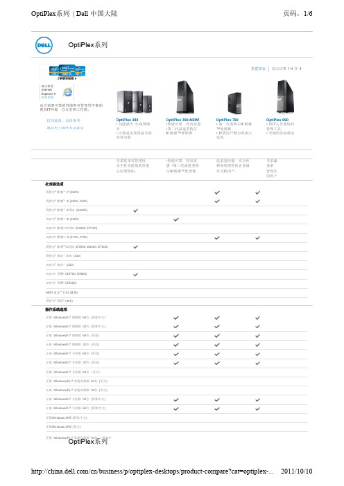
机箱
微塔式机
尺寸 (高 x 宽 x 深) 英 寸/(厘米): 16.1 x 7.4 x 17.0/(40.8 x 18.7 x 43.3)
重量(磅/千克): 26.5/12
托架数: 2个内部3.5英寸托架 (8.9 厘米) 1个外部3.5英寸托架 (8.9 厘米) 2个外部5.25英寸托架 (13.3 厘米)
外围设备选项
显示器:
Dell 入门级标准显示器以 及宽屏模拟液晶显示器: Dell E170S、E1709W 、 E190S、E1910H、 E1911 、 E2011H 和 E2211H
戴尔专业数字标准显示器 和宽屏液晶显示器: Dell P170S、P190S、 P1911 、 P2011H 、 P2211H 和 P2311H
扩展槽: 1个半高PCIe x16插槽 2个半高PCI插槽 (可选Riser卡将PCIe和 PCI插槽转为全高插槽)
供电装置(PSU): 235瓦标准PSU或可选效 率为88%的255瓦PSU; 符合能源之星5.0规范
小型机
尺寸 (高 x 宽 x 深) 英 寸/(厘米): 12.4 x 3.7 x 13.4/(31.4 x 9.3 x 34.0)
最小 重量(磅/千克) 12.57/5.7
托架数 1个内置3.5英寸托架 1个外置5.25英寸托架(纤 薄型)
扩展槽 1个半高PCIe x16插槽 1个半高PCIe x1插槽
电源装置(PSU) 标准240瓦PSU
台式机(DT):
尺寸(高 x 宽 x 深)(英 寸/[厘米]): 14.17 x 4.02 x 16.14/ (36.0 x 10.2 x 41.0)
OptiPlex 390-NEW! •性能可靠、经济实惠 •第二代高速英特尔 ® 酷睿™处理器
德尔网络C9010网络导向器和C1048P快速访问节点说明书
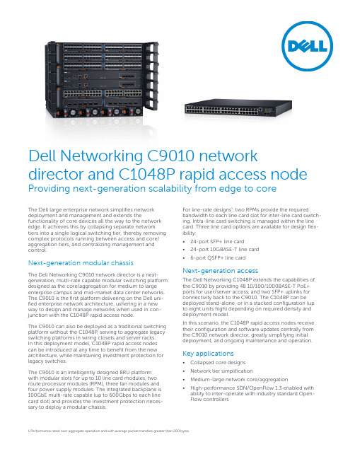
Dell Networking C9010 network director and C1048P rapid access node Providing next-generation scalability from edge to coreThe Dell large enterprise network simplifies network deployment and management and extends the functionality of core devices all the way to the network edge. It achieves this by collapsing separate network tiers into a single logical switching tier, thereby removing complex protocols running between access and core/ aggregation tiers, and centralizing management and control.Next-generation modular chassisThe Dell Networking C9010 network director is a next-generation, multi-rate capable modular switching platform designed as the core/aggregation for medium to large enterprise campus and mid-market data center networks. The C9010 is the first platform delivering on the Dell uni-fied enterprise network architecture, ushering in a new way to design and manage networks when used in con-junction with the C1048P rapid access node.The C9010 can also be deployed as a traditional switching platform without the C1048P, serving to aggregate legacy switching platforms in wiring closets and server racks.In this deployment model, C1048P rapid access nodes can be introduced at any time to benefit from the new architecture, while maintaining investment protection for legacy switches.The C9010 is an intelligently designed 8RU platformwith modular slots for up to 10 line card modules, two route processor modules (RPM), three fan modules and four power supply modules. The integrated backplane is 100GbE multi-rate capable (up to 600Gbps to each line card slot) and provides the investment protection neces-sary to deploy a modular chassis. For line-rate designs1, two RPMs provide the required bandwidth to each line card slot for inter-line card switch-ing. Intra-line card switching is managed within the line card. Three line card options are available for design flex-ibility:• 24-port SFP+ line card• 24-port 10GBASE-T line card• 6-port QSFP+ line cardNext-generation accessThe Dell Networking C1048P extends the capabilities of the C9010 by providing 48 10/100/1000BASE-T PoE+ ports for user/server access, and two SFP+ uplinks for connectivity back to the C9010. The C1048P can be deployed stand-alone, or in a stacked configuration (up to eight units high) depending on required density and deployment model.In this scenario, the C1048P rapid access nodes receive their configuration and software updates centrally from the C9010 network director, greatly simplifying initial deployment, and ongoing maintenance and operation. Key applications• Collapsed core designs• Network tier simplification• Medium-large network core/aggregation• High-performance SDN/OpenFlow 1.3 enabled with ability to inter-operate with industry standard Open-Flow controllers 1 Performance rated over aggregate operation and with average packet transfers greater than 200 bytes.• Up to 60 40GbE QSFP+ ports• Up to 248 10GbE ports (240 SFP+ or 10GBASE-T ports plus eight SFP+ ports on two RPMs)• Support for 2,000 virtual ports (via port extenders), and concurrent support for traditional Ethernet switches/devices• Side-to-side airflow (right to left)• VRF-lite enables sharing of networking infrastructure and provides L3 traffic isolation across tenants(including support for multicast and IPv6 routing)• Enhanced automation capabilities (puppet agent, REST API extensions)• Support for jumbo frames for high-end performance in virtualized environments and IP storage/servercommunication• Removable chassis mid-walls for future support of full-width modules• Tool-less mounting and optional ReadyRails™ port extenders stack up to eight units high• Embedded Open Automation Framework adds VM awareness as well as automated configuration andprovisioning capabilities to simplify the management of virtual network environmentsSpecifications: C9010 network director and C1048P rapid access nodeC9010 network director10 slot, includes 1x RPM, 1x AC PSU, 3x Fan ModulesC9010 Modular Switch, 10 slot, includes 1x RPM, 1x AC PSU, 3x Fan Modules, TAARedundant RPMC9000 RPM 2.56T, Redundant RPMLine cardsC9000 24-port 10GbE 10GBASE-T Line CardC9000 24-port 10GbE SFP+ Line CardC9000 6-port 40GbE QSFP+ Line Card Redundant power suppliesC9000 2,900W Power SupplyFansC9000 Hot Swappable Fan ModuleC1048P port extenderC1048P Port Extender, 48x 10/100/1000BASE-T PoE+ ports, 2x SFP+ ports, 2x stacking ports, 1 integrated 1000W power supply (requires C15 plug)SoftwareSoftware, Dell Networking OS9.X,Physical (C9010)Up to 240 line-rate1 1/10GBASE-T portsUp to 248 line-rate1 1/10GbE SFP+ portsUp to 60 line-rate1 40GbE QSFP+ ports3 fan modules4 2,900W power suppliesUp to 2 RPMs1 RJ45 console/management port with RS232 signaling and 1 USB-B port (per RPM)Size: 8 RU, 13.9”h x 17.4” w x 18.0” d (35.26 cm h x 44.20 cm w x 45.70 cm d)Weight: 55.4 lbs (25.2 kg) empty, 151.3 to 165.3 lbs (68.8 to 75.1 kg) fully loaded, depending on line cards installedNominal Input Voltage: 100/120 VAC 50/60 Hz and 200/240 VAC 50/60 HzMax input current per power supply @ 1,450W (100/120V): 16A at 100V, 14A at 120VMax input current per power supply @ 2,900W (200/240V): 16A at 200V, 14A at 240VMax system power input (using 4 power supplies): 2,950 VAMax. power consumption: 2,950WMax. thermal output: 10,066 BTU/hrTyp. power consumption: 1410-2400 Watts fullyloaded, depending on line cards installedMax. operating specifications:Operating temperature: 32° to 113°F (0° to 45°C)Operating humidity: 5 to 85% (RH), non-condensingOperating altitude: 0ft to 10,000ft above sea levelMax. non-operating specifications:Storage temperature: –40° to 158°F (–40° to70°C)Storage humidity: 5 to 95% (RH), non-condensingPhysical (C1048P)48 10/100/1000BASE-T RJ45 PoE+2 integrated SFP+ uplink ports2 integrated 21Gbps stack portsConsole/management port with RS232 signalingUSB-A portSize: 1 RU, 1.7”h x 17.3” w x 10.1” d (4.4 cm h x 44.0cm w x 38.7 cm d)Weight: 15.0 lbs (6.8 kg)Max. operating specifications:Operating temperature: 32° to 113°F (0° to 45°C)Operating humidity: 5 to 95% (RH), non-condensingOperating altitude: 0ft to 10,000ft above sea levelMax. non-operating specifications:Storage temperature: –40° to 149°F (–40° to65°C)Storage humidity: 5 to 95% (RH), non-condensingPoE/PoE+ Power Budget: 850W using integratedpower supply. 1,700W when used in conjunctionwith MPS1000RedundancyHot swappable redundant RPMsHot swappable redundant power suppliesPerformanceMAC addresses: 160KIPv4 routes: 128k (in scaled mode); 16k in defaultmodeIPv6 routes: 32K (shared CAM space with IPv4)RPM switch fabric capacity: 2.56Tbps (full-duplex)1.28Tbps (half-duplex)RPM throughput: 1,462 MppsLine Card switch fabric capacity: 1.44Tbps (full-duplex) 720Gbps (half-duplex)Line Card throughput: 714 MppsLink aggregation: 16 links per group, 128 groupsper stackQueues per port: 8 queuesLayer 2 VLANs: 4KMSTP : 64 instancesVRF-lite: 32 instances (64 in future release)Line-rate Layer 2 switching: all protocols,including IPv4 and IPv6Line-rate Layer 3 routing: IPv4 and IPv6IPv4 host table size 32KIPv6 host table size 16KIPv4 Multicast table size 4KLAG load balancing: based on Layer 2, IPv4 orIPv6 headersIEEE compliance802.1AB LLDP802.1BR (Tagging/Detection/Distribution)802.1D Bridging, STP802.1p L2 Prioritization802.1Q VLAN Tagging, Double VLAN Tagging,GVRP802.1s MSTP802.1w RSTP802.1X Network Access Control802.3ab Gigabit Ethernet (1000BASE-T)802.3ac Frame Extensions for VLAN Tagging802.3ad Link Aggregation with LACP802.3ae 10 Gigabit Ethernet (10GBASE-X)on optical ports802.3af802.3at802.3u Fast Ethernet (100BASE-TX) on mgmt ports802.3x Flow Control802.3z Gigabit Ethernet (1000BASE-X)ANSI/TIA-1057 LLDP-MEDForce10 PVST+MTU 12,000 bytesKey features2RFC and I-D compliance3376 IGMPv3MSDPdraft-ietf-pim-sm-v2-new-05PIM-SMwGeneral Internet protocols768 UDP793 TCP854 Telnet959 FTPGeneral IPv4 protocols791 IPv4792 ICMP826 ARP1027 Proxy ARP1035 DNS (client)1042 EthernetTransmission1305 NTPv31519 CIDR1542 BOOTP (relay)1812 Requirements forIPv4 Routers1918 Address Allocationfor Private Internets2474 Diffserv Fieldin IPv4 and Ipv6Headers2596 Assured ForwardingPHB Group3164 BSD Syslog3195 Reliable Delivery forSyslog3246 Expedited AssuredForwarding4364 VRF-lite (IPv4 VRFwith OSPF, BGP, IS-IS, and v4 multicast)5798 VRRPGeneral IPv6 protocols1981 Path MTU Discovery Features2460 Internet Protocol, Version 6 (IPv6) Specification2464 Transmission of IPv6 Packets over Ethernet Networks2710 Multicast Listener Discovery (MLD) for IPv6 2711 IPv6 Router Alert Option3810 Multicast Listener Discovery Version 2 (MLDv2) for IPv64007 IPv6 Scoped Address Architecture4213 Basic Transition Mechanisms for IPv6 Hosts andRouters4291 IPv6 Addressing Architecture4443 ICMP for IPv64861 Neighbor Discovery for IPv64862 IPv6 Stateless Address Autoconfiguration 5095 Deprecation of Type 0 Routing Headers in IPv6IPv6 Management support (telnet, FTP, TACACS, RADIUS, SSH, NTP)VRF-Lite (IPv6 VRF with OSPFv3, BGPv6, and IS-IS) RIP1058 RIPv1 2453 RIPv2OSPF (v2/v3)1587 NSSA4552 Authentication2328 OSPFv2 OSPFv32370 Opaque LSA (Partial)5340 OSPF for IPv6BGP1997 Communities2385 MD52545 BGP-4 Multiprotocol Extensions for IPv6 Inter-DomainRouting2439 Route Flap Damping2796 Route Reflection2842 Capabilities2858 Multiprotocol Extensions2918 Route Refresh3065 Confederations4360 Extended Communities4893 4-byte ASN5396 4-byte ASN representationsdraft-ietf-idr-bgp4-20 BGPv4draft-michaelson-4byte-as-representation-054-byte ASN Representation (partial)draft-ietf-idr-add-paths-04.txt ADD PATHMulticast1112 IGMPv12236 IGMPv23376 IGMPv3MSDPdraft-ietf-pim-sm-v2-new-05PIM-SMwRFC4602 Protocol Independent MulticastRFC4610 Anycast-RP Using PIMRFC5015 Bidirectional PIMRFC5059 Bootstrap Router (BSR) Mechanism forPIMRFC5294 Host Threats to PIMRFC5384 PIM Join Attribute FormatRFC5496 Reverse Path Forwarding Vector TLVRFC5796 Authentication and Confidentiality inPIM-SM Link-Local MessagesRFC6166 A Registry for PIM Message TypesRFC6226 PIM Group-to-Rendezvous-PointMappingRFC6395 An Interface Identifier (ID) Hello Optionfor PIMRFC6420 PIM Multi-Topology ID Join AttributeRFC6559 A Reliable Transport Mechanism forPIMNetwork management1155 SMIv11157 SNMPv11212 Concise MIB Definitions1215 SNMP Traps1493 Bridges MIB1850 OSPFv2 MIB1901 Community-Based SNMPv22011 IP MIB2096 IP Forwarding Table MIB2578 SMIv22579 Textual Conventions for SMIv22580 Conformance Statements for SMIv22618 RADIUS Authentication MIB2665 Ethernet-Like Interfaces MIB2674 Extended Bridge MIB2787 VRRP MIB2819 RMON MIB (groups 1, 2, 3, 9)2863 Interfaces MIB3273 RMON High Capacity MIB3410 SNMPv33411 SNMPv3 Management Framework3412 Message Processing and Dispatching for theSimple Network Management Protocol (SNMP)3413 SNMP Applications3414 User-based Security Model (USM) forSNMPv33415 VACM for SNMP3416 SNMPv23417 Transport mappings for SNMP3418 SNMP MIB3434 RMON High Capacity Alarm MIB3584 Coexistance between SNMP v1, v2 and v34022 IP MIB4087 IP Tunnel MIB4113 UDP MIB4133 Entity MIB4292 MIB for IP4293 MIB for IPv6 Textual Conventions4502 RMONv2 (groups 1,2,3,9)5060 PIM MIBANSI/TIA-1057 LLDP-MED MIBDell_ITA.Rev_1_1 MIBdraft-grant-tacacs-02 TACACS+draft-ietf-idr-bgp4-mib-06 BGP MIBv1IEEE 802.1AB LLDP MIBIEEE 802.1AB LLDP DOT1 MIBIEEE 802.1AB LLDP DOT3 MIB sFlowv5 sFlowv5 MIB (version 1.3)FORCE10-BGP4-V2-MIB Force10 BGP MIB(draft-ietf-idr-bgp4-mibv2-05)FORCE10-IF-EXTENSION-MIBFORCE10-LINKAGG-MIBFORCE10-COPY-CONFIG-MIBFORCE10-PRODUCTS-MIBFORCE10-SMIFORCE10-TC-MIBFORCE10-TRAP-ALARM-MIBDELL-NETWORKING-CHASSIS-MIBDELL-NETWORKING-FPSTATS-MIBf10-bmp.mibf10-bpstats.mibf10-dcbx.mibf10-fib.mibf10-fip-snooping.mibf10-isis.mibf10-openFlow.mibf10-VirtualLinkTrunk.mibRFC5240 PIM Bootstrap Router MIBRFC5060 PIM MIBRegulatory complianceSafetyUL/CSA 60950-1, Second EditionEN 60950-1, Second EditionIEC 60950-1, Second Edition Including AllNational Deviations and Group DifferencesEN 60825-1 Safety of Laser ProductsPart 1: Equipment Classification Requirements andUser’s GuideEN 60825-2 Safety of Laser ProductsPart 2: Safety of Optical Fibre CommunicationSystemsFDA Regulation 21 CFR 1040.10 and 1040.11EmissionsAustralia/New Zealand: AS/NZS CISPR 22: Class ACanada: ICES-003, Issue-4, Class AEurope: EN 55022: (CISPR 22:), Class AJapan: VCCI Class AUSA: FCC CFR 47 Part 15, Subpart B: Class AImmunityEN 300 386 EMC for Network EquipmentEN 55024EN 61000-3-2: Harmonic Current EmissionsEN 61000-3-3: Voltage Fluctuations and FlickerEN 61000-4-2: ESDEN 61000-4-3: Radiated ImmunityEN 61000-4-4: EFTEN 61000-4-5: SurgeEN 61000-4-6: Low Frequency ConductedImmunityRoHSAll C Series components are EU RoHS compliant.CertificationsAvailable with US Trade Agreements Act (TAA)complianceUSGv6 Host and Router Certified on DellNetworking OS9.5 and greater*IPv6 Ready for both Host and Router**USGv6, IPv6 Ready, and UC APL certifications contingent upon successful test completion32.56Tbps RPM with 4 6-port 40GbE linecard with pluggableQSFP+ modules, 24-port 10GbE linecard with pluggableSFP+ modules,24-port 10GbE linecard with 10GBASE-TRJ45 ports,48-port 1GbE4Cables(sold separately)CablesCable, SFP+ to SFP+,10GbE, Copper TwinaxDirect Attach Cable,0.5 MeterCable, SFP+ to SFP+,10GbE, Copper TwinaxDirect Attach Cable, 1MeterCable, SFP+ to SFP+,10GbE, Copper TwinaxDirect Attach Cable, 3MetersCable, SFP+ to SFP+,10GbE, CopperTwinax Direct AttachCable, 5 MetersCable, SFP+ to SFP+,10GbE, CopperTwinax Direct AttachCable, 7 MetersCables1 meter QSFP+ toQSFP+ OM3 MTP FiberCable, Requires QSFP+Optics3 meter QSFP+ toQSFP+ OM3 MTP FiberCable, Requires QSFP+Optics5 meter QSFP+ toQSFP+ OM3 MTP FiberCable, Requires QSFP+Optics7 meter QSFP+ toQSFP+ OM3 MTP FiberCable, Requires QSFP+Optics10 meter QSFP+ toQSFP+ OM3 MTPFiber Cable, RequiresQSFP+ Optics25 meter QSFP+ toQSFP+ OM3 MTPFiber Cable, RequiresQSFP+ Optics50 meter QSFP+ toQSFP+ OM3 MTPFiber Cable, RequiresQSFP+ Optics75 meter QSFP+ toQSFP+ OM3 MTPFiber Cable, RequiresQSFP+ Optics100 meter QSFP+to QSFP+ OM3 MTPFiber Cable, RequiresQSFP+ OpticsCablesCable, SFP+ to SFP+,10GbE, Copper TwinaxDirect Attach Cable,0.5 Meter Cable,SFP+ to SFP+, 10GbE,Copper Twinax DirectAttach Cable, 1 MeterCable, SFP+ to SFP+,10GbE, Copper TwinaxDirect Attach Cable, 3MetersCable, SFP+ to SFP+,10GbE, CopperTwinax Direct AttachCable, 5 MetersCable, SFP+ to SFP+,10GbE, CopperTwinax Direct AttachCable, 7 MetersCable,None Stacking CablesStacking cable 0.5mStacking cable 1mStacking cable 3mCablesCable, SFP+ to SFP+,10GbE, Copper TwinaxDirect Attach Cable,0.5 MeterCable, SFP+ to SFP+,10GbE, Copper TwinaxDirect Attach Cable, 1MeterCable, SFP+ to SFP+,10GbE, Copper TwinaxDirect Attach Cable, 3MetersCable, SFP+ to SFP+,10GbE, Copper TwinaxDirect Attach Cable, 5MetersCable, SFP+ to SFP+,10GbE, Copper TwinaxDirect Attach Cable, 7MetersMaximumPower/Thermal190W/648 BTU/hr125W/426 BTU/hr170W/580 BTU/hr205W/699 BTU/hr1,738W/6,070 BTU/hr DRAM/Flash24GB/32GB2GB/4GB2GB/4GB2GB/4GB1GB/256MBPacket Buffer9MB9MB9MB9MB4MBWeight 4.18kg(9.20lbs) 2.11kg(4.63lbs) 2.74kg(6.03lbs) 2.74kg(6.03lbs) 6.81kg(14.99lbs)Learn More at /Networking© 2015 Dell Inc. All rights reserved. Dell and the Dell logo are trademarks of Dell, Inc. All other company names are trademarks of their respectiveholders. All other company names are trademarks of their respective holders. Information in this document is subject to change without notice. DellInc. assumes no responsibility for any errors that may appear in this document.September 2015 | Version 1Dell_Networking_C9010_C1048P_SpecSheet。
DELL服务器报价单

6核AMD4234(3.1G)/4GB(2X2G)/1TB SATA*1/H200/750W电源/无光驱 12背板(3.5) 3年7X24服务(热插拔) ¥6,500.00 8核AMD6212(2.6G)*2/4GB(2X2G)/300G SAS 2.5寸*1/H200/750W电源/6背板2.5寸 3年7X24服务(热插拔) ¥8,800.00 英特尔酷睿i3-3220(3.1GHz)/2G NECC/500G(SATA 7.2K)/NVS295/DVDRW/键鼠/3年5*8 ¥4,000.00 ¥4,700.00 ¥4,500.00 ¥6,100.00 ¥6,300.00 ¥6,700.00 ¥7,200.00
至强四核E5-1603(2.8GHz)/2G/500G(SATA 7.2K)/NVS300 512M/DVDRW/键鼠/3年5*8 至强四核E5-1607(3.0GHz)/2G/500G(SATA 7.2K)/NVS300 512M/DVDRW/键鼠/3年5*8 至强四核E5-1620(3.6GHz)/2G/500G(SATA 7.2K)/NVS300 512M/DVDRW/键鼠/3年5*8 至强四核E5-2603(1.8GHz)/2G/500G(SATA 7.2K)/NVS300 512M/DVDRW/键鼠/3年5*8
T1650
至强四核E3-1220 v2(3.1GHz)/2G NECC/500G(SATA 7.2K)/NVS295/DVDRW/键鼠/3年5*8 至强四核E3-1225 v2(3.2GHz)/2G NECC/500G(SATA 7.2K)/DVDRW/键鼠/3年5*8
工 作 站 T3600
T5600
作 站
T7600
至强四核E5-2603(1.8GHz)/2G/500G(SATA 7.2K)/NVS300 512M/DVDRW/键鼠/3年5*8
MT-100电子产品使用说明书

MT-100Motorcycle Tracking DeviceUSER MANUALa c k i n g T h e W o r l d .co mGeneral NotesTrackingTheWorld offers this information as a service to its customers, to support application and engineering efforts that use the products designed by TrackingTheWorld. The information provided is based upon requirements specifically provided to TrackingTheWorld by the customers. TrackingTheWorld has not undertaken any independent search for additional relevant information, including any information that may be in the customer’s possession. Furthermore, system validation of this product designed by TrackingTheWorld within a larger electronic system remains the respon sibility of the customer or the customer’s system integrator. All specifications supplied herein are subject to change.CopyrightThis document contains proprietary technical information which is the property of TrackingTheWorld, copying of this document and giving it to others and the using or communication of the contents thereof, are forbidden without express authority. Offenders are liable to the payment of damages. All rights reserved in the event of grant of a patent or the registration of a utility model or design. All specification supplied herein are subject to change without notice at any time.Copyright © TrackingTheWorld 2016For More Information: Please contact TrackingTheWorld, 1633 Bayshore Highway, Suite 390, Burlingame, CA. 94010, USA Phone: +1.650.692.8100 – Email: *************************– Website: ContentsContents (3)Table Index (4)Figure Index (5)1. Introduction (7)1.1. Reference (7)1.2. Terms and Abbreviations (7)2. Product Overview (8)2.1. Appearance (8)2.2. Parts List (8)2.3. Interface Definition (9)3. Getting Started (10)3.1. Installing a SIM Card (10)3.2. Switch the set on/off (10)3.3. Reset Key (11)3.4. USB connector (11)3.5. Power Connection (11)3.6. Ignition Detection (12)3.7. Digital Input (12)3.8. Analog Input (13)3.9. Digital Output (13)3.10. Relay Output (14)3.11. Device Status LED (15)For More Information: Please contact TrackingTheWorld, 1633 Bayshore Highway, Suite 390, Burlingame, CA. 94010, USA Phone: +1.650.692.8100 – Email: *************************– Website: Table 1: MT-100 Protocol Reference (7)Table 2: Terms and Abbreviations (7)Table 3: Part List (8)Table 4: Description of MT-100 User Cable (9)Table 5: Electrical Characteristics of Ignition Detection (12)Table 6: Electrical Characteristics of the digital inputs (12)Table 7: Electrical Characteristics of Digital Output (13)Table 8: Definition of Device status and LED (16)For More Information: Please contact TrackingTheWorld, 1633 Bayshore Highway, Suite 390, Burlingame, CA. 94010, USA Phone: +1.650.692.8100 – Email: *************************– Website: Figure 1.Appearance of MT-100 (8)Figure 2.SIM Card Installation (10)Figure 3.Typical Power Connection (11)Figure 4.Typical Ignition Detection (12)Figure 5.Typical Digital Input Connection (13)Figure 6.Typical Analog Input Connection (13)Figure 7.Typical Connection with Siren (14)Figure 8.Typical Connection with Relay (14)Figure 9.MT-100 LED on the Case (15)For More Information: Please contact TrackingTheWorld, 1633 Bayshore Highway, Suite 390, Burlingame, CA. 94010, USA Phone: +1.650.692.8100 – Email: *************************– Website: For More Information: Please contact TrackingTheWorld, 1633 Bayshore Highway, Suite 390, Burlingame, CA. 94010, USA Phone: +1.650.692.8100 – Email: *************************– Website: 1. IntroductionThe MT-100 is a powerful GPS locator designed for vehicle or asset tracking. It has superior receiver sensitivity, fast TTFF (Time to First Fix) and supports Quad-Band GSM frequencies 850/900/1800/1900, its location can be monitored in real time or be periodically tracked by a backend server or other specified terminals. The MT-100 has multiple input/output interfaces that can be used for monitoring or controlling external devices. Based on the integrated @Track protocol, the MT-100 can communicate with a backend server through the GPRS/GSM network to transfer reports of Emergency, geo-fence boundary crossings, low backup battery or scheduled GPS position as well as many other useful functions. Users can also use MT-100 to monitor the status of a vehicle and control the vehicle by its external relay output. System Integrators can easily setup their tracking systems based on the full-featured @Track protocol.This device complies with part 15B, part 22 and part 24 of the FCC rules. Operation is subject to the following two conditions: (1) this device may not cause harmful interference (2) this device must accept any interference, including interference that may cause undesired operation.1.1.Reference1.2.Terms and AbbreviationsFor More Information: Please contact TrackingTheWorld, 1633 Bayshore Highway, Suite 390, Burlingame, CA. 94010, USA Phone: +1.650.692.8100 – Email: *************************– Website: Copyright © TrackingTheWorld. All rights reserved. Information in this publication supersedes that in all previously published material. Specification and price2. Product Overview2.1.AppearanceFigure 1. Appearance of MT-1002.2.Parts ListPictureFor More Information: Please contact TrackingTheWorld, 1633 Bayshore Highway, Suite 390, Burlingame, CA. 94010, USA Phone: +1.650.692.8100 – Email: *************************– Website: Copyright © TrackingTheWorld. All rights reserved. Information in this publication supersedes that in all previously published material. Specification and price2.3.Interface DefinitionThere are 8 wires on MT-100 User Cable which contain the connection for power, ignition input, digital input, analog input, siren output, cut output etc. The user cable’s definition is shown in following table.For More Information: Please contact TrackingTheWorld, 1633 Bayshore Highway, Suite 390, Burlingame, CA. 94010, USA Phone: +1.650.692.8100 – Email: *************************– Website: Copyright © TrackingTheWorld. All rights reserved. Information in this publication supersedes that in all previously published material. Specification and priceFor More Information: Please contact TrackingTheWorld, 1633 Bayshore Highway, Suite 390, Burlingame, CA. 94010, USAPhone: +1.650.692.8100 – Email: ************************* – Website: Copyright © TrackingTheWorld. All rights reserved. Information in this publication supersedes that in all previously published material. Specification and price 3. Getting Started3.1. Installing a SIM CardStep 1: Remove the cover by screwdriver.Step 2: Make sure the contact area is facing down, insert the SIM into the slot. Step 3: Install the SIM card cover.Figure 2. SIM Card Installation3.2. Switch the set on/offThere are two methods to Power on MT-100: - MT-100 external power turned on.- Connect MT-100 to PC with user cable.When the external power or USB cable power is removed, MT-100 will switch to internal backup battery and keep on running. When internal backup battery is exhausted, MT-100 will give a report and then turn off.Note:1-External power and User USB power can be present at same time.2-For USB port current limitation, when configuring MT-100 by user cable, please let backup battery onusing.For More Information: Please contact TrackingTheWorld, 1633 Bayshore Highway, Suite 390, Burlingame, CA. 94010, USAPhone: +1.650.692.8100 – Email: ************************* – Website: Copyright © TrackingTheWorld. All rights reserved. Information in this publication supersedes that in all previously published material. Specification and price There is one method to turn off MT-100.- Remove the external power and USB power. - Press the reset key.Note:MT-100 PWR LED will off.3.3. Reset KeyThere is a reset key behind the SIM card cover. If the power wire is connected to vehicle power, the system will reboot when the key is pressed; if the system is powered by the backup battery and the power wire is not be connected to vehicle power, the system will shutdown when the key is pressed. Note:When you finished the firmware upgrade, please press the reset key to reboot the system before configuring the terminal.3.4. USB connectorThere is a USB connector on MT-100 which is beside the SIM card. With the USB connector and the DATA_CABLE_M, user can configure the system or download firmware. As long as the DATA_CABLE_M is plugged in, the system will boot.3.5. Power ConnectionThe red wire is power wire and the black wire is ground wire. The input voltage range for this device is from 8V to 32V. The device is designed to be installed in vehicles that operate on 12V or 24V systems without the need for external transformers.Figure 3. Typical Power ConnectionFor More Information: Please contact TrackingTheWorld, 1633 Bayshore Highway, Suite 390, Burlingame, CA. 94010, USAPhone: +1.650.692.8100 – Email: ************************* – Website: Copyright © TrackingTheWorld. All rights reserved. Information in this publication supersedes that in all previously published material. Specification and price 3.6. Ignition DetectionInactive0V to 3V or OpenFigure 4. Typical Ignition DetectionThe white wire is used for ignition detection. It is strongly recommended to connect this wire to ignition key “RUN” position as shown up.An alternative to connecting to the ignition switch is to find a non-permanent power source that is only available when the vehicle is running. For example the power source for the FM radio.Ignition signal can be configured to start transmitting information to backend server when ignition is on; and enter power saving mode when ignition is off.3.7. Digital InputThere is a general purpose digital input which is the blue wire on MT-100 User Cable, and it is a negative trigger. The digital input is recommended to support panic button function.The following diagram shows the recommended connection of the digital input.For More Information: Please contact TrackingTheWorld, 1633 Bayshore Highway, Suite 390, Burlingame, CA. 94010, USAPhone: +1.650.692.8100 – Email: ************************* – Website: Copyright © TrackingTheWorld. All rights reserved. Information in this publication supersedes that in all previously published material. Specification and priceFigure 5.Typical Digital Input Connection3.8. Analog InputThere is an analog input which is the green wire on MT-100 User Cable, and the analog input voltage range is from 0 to 32V. The following diagram shows the recommended connection.Figure 6. Typical Analog Input Connection3.9. Digital OutputThere is an output which is the brown wire on MT-100 User Cable. This output is used to drive a siren and the maximum drive current is 750mA. When the siren output is enabled, the voltage on the siren output is determined by the system power level, if the system power is 12V, then the siren output voltage is 12V.For More Information: Please contact TrackingTheWorld, 1633 Bayshore Highway, Suite 390, Burlingame, CA. 94010, USAPhone: +1.650.692.8100 – Email: ************************* – Website: Copyright © TrackingTheWorld. All rights reserved. Information in this publication supersedes that in all previously published material. Specification and priceFigure 7. Typical Connection with Siren3.10. Relay OutputThere is a built-in cut relay on MT-100, and it is a NC (Normal Close) type relay which maximum switching voltage is 12VDC and maximum continuous current is 20A. On MT-100 user cable one 18AWG yellow wire is connected to the relay NC contact and the other 18AWG yellow wire is connected to the relay COM contact. In certain instances the two wires will be connected together. Note:1: The relay output can be latched by the software, so even if the MT-100 is restart or power down in some cases, the relay output will not change. To use the latch function the main power and backup battery should be connected. Otherwise the relay will be always in normal close status.2: The relay works only with 12V main power. Use it when the main power is 24V may result in damaging.3: Many modern relays come with a fly-back diode pre-installed internal to the relay itself. If the relay has this diode, ensure the relay polarity is properly connected. If this diode is not internal, it should be added externally. A common diode such as a 1N4004 will work in most circumstances.Figure 8. Typical Connection with RelayFor More Information: Please contact TrackingTheWorld, 1633 Bayshore Highway, Suite 390, Burlingame, CA. 94010, USAPhone: +1.650.692.8100 – Email: ************************* – Website: Copyright © TrackingTheWorld. All rights reserved. Information in this publication supersedes that in all previously published material. Specification and price 3.11. Device Status LEDFigure 9.MT-100 LED on the CaseFor More Information: Please contact TrackingTheWorld, 1633 Bayshore Highway, Suite 390, Burlingame, CA. 94010, USAPhone: +1.650.692.8100 – Email: ************************* – Website: Copyright © TrackingTheWorld. All rights reserved. Information in this publication supersedes that in all previously published material. Specification and price Table 8: Definition of Device status and LEDNote:1 - GSM LED cannot be configured.2 - GPS LED and PWR LED can be configured to turn off after a period of time using the configuration tool3 - Fast flashing is about 60ms ON/ 780ms OFF4 - Slow flashing is about 60ms ON/ 1940ms OFF。
DellOptiPlex9010
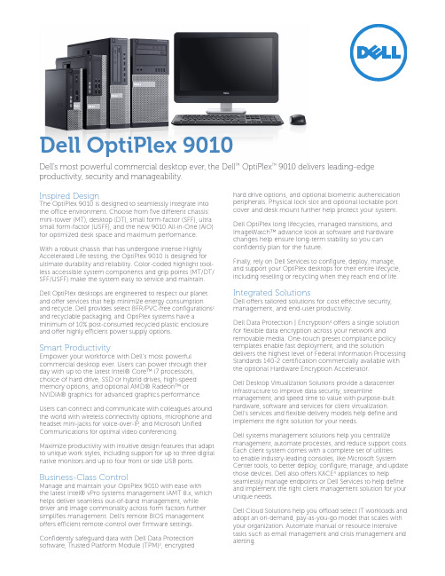
Inspired DesignThe OptiPlex 9010 is designed to seamlessly integrate into the office environment. Choose from five different chassis: mini-tower (MT), desktop (DT), small form-factor (SFF), ultra small form-factor (USFF), and the new 9010 All-in-One (AiO) for optimized desk space and maximum performance.With a robust chassis that has undergone intense Highly Accelerated Life testing, the OptiPlex 9010 is designed for ultimate durability and reliability. Color-coded highlight tool-less accessible system components and grip points (MT/DT/ SFF/USFF) make the system easy to service and maintain. Dell OptiPlex desktops are engineered to respect our planet and offer services that help minimize energy consumption and recycle. Dell provides select BFR/PVC-free configurations1 and recyclable packaging, and OptiPlex systems have a minimum of 10% post-consumed recycled plastic enclosure and offer highly efficient power supply options.Smart ProductivityEmpower your workforce with Dell’s most powerful commercial desktop ever. Users can power through their day with up to the latest Intel® Core™ i7 processors, choice of hard drive, SSD or hybrid drives, high-speed memory options, and optional AMD® Radeon™ or NVIDIA® graphics for advanced graphics performance. Users can connect and communicate with colleagues around the world with wireless connectivity options, microphone and headset mini-jacks for voice-over-IP, and Microsoft Unified Communications for optimal video conferencing.Maximize productivity with intuitive design features that adapt to unique work styles, including support for up to three digital native monitors and up to four front or side USB ports. Business-Class ControlManage and maintain your OptiPlex 9010 with ease withthe latest Intel® vPro systems management iAMT 8.x, which helps deliver seamless out-of-band management, while driver and image commonality across form factors further simplifies management. Dell‘s remote BIOS management offers efficient remote-control over firmware settings. Confidently safeguard data with Dell Data Protection software, Trusted Platform Module (TPM)2, encrypted hard drive options, and optional biometric authentication peripherals. Physical lock slot and optional lockable port cover and desk mount further help protect your system. Dell OptiPlex long lifecycles, managed transitions, and ImageWatch™ advance look at software and hardware changes help ensure long-term stability so you can confidently plan for the future.Finally, rely on Dell Services to configure, deploy, manage, and support your OptiPlex desktops for their entire lifecycle, including reselling or recycling when they reach end of life. Integrated SolutionsDell offers tailored solutions for cost effective security, management, and end-user productivity.Dell Data Protection | Encryption4 offers a single solution for flexible data encryption across your network and removable media. One-touch preset compliance policy templates enable fast deployment, and the solution delivers the highest level of Federal Information Processing Standards 140-2 certification commercially available with the optional Hardware Encryption Accelerator.Dell Desktop Virtualization Solutions provide a datacenter infrastructure to improve data security, streamline management, and speed time to value with purpose-built hardware, software and services for client virtualization. Dell’s services and flexible delivery models help define and implement the right solution for your needs.Dell systems management solutions help you centralize management, automate processes, and reduce support costs. Each client system comes with a complete set of utilitiesto enable industry-leading consoles, like Microsoft System Center tools, to better deploy, configure, manage, and update those devices. Dell also offers KACE4 appliances to help seamlessly manage endpoints or Dell Services to help define and implement the right client management solution for your unique needs.Dell Cloud Solutions help you offload select IT workloads and adopt an on-demand, pay-as-you-go model that scales with your organization. Automate manual or resource intensive tasks such as email management and crisis management and alerting.Dell OptiPlex 9010Dell’s most powerful commercial desktop ever, the Dell™ OptiPlex™ 9010 delivers leading-edge productivity, security and manageability.Discover professional class desktops at /OptiPlex1. O ptiPlex 9010 small form factor is brominated flame retardant free (BFR-free) and polyvinyl chloride free (PVC-free); meeting the definition of BFR-/PVC-free as set forth in the iNEMI Position Statement on the ‘Definition of Low-Halogen Electronics (BFR-/CFR-/PVC-free)’. Plastic parts contain less than 1,000 ppm (0.1%) of bromine (if the Br source is from BFRs) and less than 1,000 ppm (0.1%) of chlorine (if the Cl source is from CFRs or PVC or PVC copolymers). All printed circuit board (PCB) and substrate laminates contain bromine/ chlorine total less than 1,500 ppm (0.15%) with a maximum chlorine of 900 ppm (0.09%) and maximum bromine being 900 ppm (0.09%).2. TPM: TPM is not available in all regions.3. Availability and terms of Dell Services vary by region. For more information, visit /servicedescriptions.4. Offering may vary by region.5. System Memory and Graphics: Significant system memory may be used to support graphics, depending on system memory size and other factors.6. 4GB or Greater System Memory Capability: A 64-bit operating system is required to support 4GB or more of system memory.7. Hard Drive: GB means 1 billion bytes and TB equals 1 trillion bytes; actual capacity varies with preloaded material and operating environment and will be less.8. P SU: This form factor utilizes a more efficient Active Power Factor Correction (APFC) power supply. Dell recommends only Universal Power Supplies (UPS) based on Sine Waveoutput for APFC PSUs, not an approximation of a Sine Wave, Square Wave, or quasi-Square Wave (see UPS technical specifications). If you have questions please contact the manufacturer to confirm the output type.9. Computrace: Not a Dell offer. Certain conditions apply. For full details, see terms and conditions at .10. Systems Management Options:• Intel® vPro Technology - Fully vPro-capable at point of purchase; the vPro systems management option requires vPro processors. Includes support for Intel Advanced Management Technology (AMT) 8.x.• Intel® Standard Manageability - Fully enabled at point of purchase, the Intel Standard Management option is a subset of the AMT features. ISM is not upgradeable to vPro technology post-purchase.• No Out-of-Band Systems Management - This option entirely removes Intel out of band systems (OOB) management features. The system can still support in band management. OOB management support through AMT cannot be upgraded post-purchase.11. Limited Hardware Warranty: For copy of Ltd Hardware Warranty, write Dell USA LP, Attn: Warranties, One Dell Way, Round Rock, TX 78682 or see /warranty.12. N ext Business Day Onsite Service after Remote Diagnosis: Remote Diagnosis is determination by online/phone technician of cause of issue; may involve customer access to insideof system and multiple or extended sessions. If issue is covered by Limited Hardware Warranty (/warranty) and not resolved remotely, technician and/or part will be dispatched, usually within 1 business day following completion of Remote Diagnosis. Availability varies. Other conditions apply.13. 3rd generation CPUs natively support 3 displays with the integrated CPU graphics. Three simultaneous display output requires one DP port with a maximum resolution of2500x1600 at 60Hz refresh rate and a DP and VGA port with max resolutions of 1920x1200 at 60Hz refresh rates.14. Please refer to for specific country registration rating and participation.。
戴尔 OptiPlex 9010 技术指南说明书
DELLTMTABLE OF CONTENTSOVERVIEWMini Tower Computer (MT) View3-4Desktop Computer (DT) View5-6Small Form Factor Computer (SFF) View7-89-10 Ultra Small Form Factor Computer (USFF) ViewOperating System, Chipset11Processor12Memory13Drives and Removable Storage, System Board Connectors14-15Graphics/Video Controller16External Ports/Connectors16Communications—Network Adapter (NIC), Wireless17Audio and Speakers, Keyboard and Mouse17Security, Service and Support, Software18System Dimensions (Physical)19System Board Connector Maximum Allowable Dimensions19System Level Environmental and Operating Conditions20Power21-22Audio23Communications23-28Graphics/Video Controller29-31Hard Drives32-39 Optical Drive40-42 Media Card Reader 43 BIOS Defaults44 Chassis Enclosure and Ventilation Requirements45 Acoustic Noise Emission Information46-49MINI TOWER COMPUTER (MT) VIEWMT System Board ComponentsDESKTOP COMPUTER (DT) VIEWDT System Board ComponentsSMALL FORM FACTOR COMPUTER (SFF) VIEWSFF System Board ComponentsULTRA SMALL FORM FACTOR COMPUTER (USFF) VIEWUSFF System Board ComponentsMARKETING SYSTEM CONFIGURATIONSNO TE: O ff e rin gs ma y v a ry by c o u nt ry.For mo re i n f o rma ti o n re ga rdi ng the c onfigu ra ti on o f y ou r c om pu ter,c lic k Sta r t>H elp a nd Su ppo r t a nd s elec t th e o p ti on to v i ew i n forma ti o n a bo u t y ou r c ompu t er.OPERATING SYSTEMCHIPSETPROCESSOR1NOTE: Global Standard Products (GSP) are a subset of Dell’s relationship products that are managed for availability and synchro-nized transitions on a worldwide basis. They ensure the same platform is available for purchase globally. This allows customers to reduce the number of configurations managed on a worldwide basis, thereby reducing their costs. They also enable companies to implement global IT standards by locking in specific product configurations worldwide. The following GSP processors identi-fied below will be made available to Dell customers.NOTE: Processor numbers are not a measure of performance. Processor availability subject to change and may vary by region/ country.1 3rd generation CPUs natively support 3 displays with the integrated CPU graphics. Three simultaneous display output requires one DP port witha maximum resolution of 2500x1600 at 60Hz refresh rate and a DP and VGA port with max resolutions of 1920x1200 at 60Hz refresh rates.2 Post launch CPU, available from June for G860; July for G640, i5 3470/S, i5 3570/S, i5 3475S.3 Available at launch, will be replaced in June or July, i5 3470/S replace i5 3450/S; i5 3570/S replace i5 3550/S; G860 replace G850; G640 re-place G630.MEMORYNOTE: Memory modules should be installed in pairs of matched memory size, speed, and technology. If the memory modules are not installed in matched pairs, the computer will continue to operate, but with a slight reduction in performance. The entire memory range is available to 64-bit operating systems.1 To fully utilize 4GB or more of memory requires a 64-bit enabled processor and 64-bit operating system. With 32-bit OS, the total amount of available memory will be less than 4GB. The amount less depends on the actual system configuration.2 1600MHz memory will only perform as 1600MHz memory when 3rd generation CPUs are used. It will perform as 1333MHz memory if 2nd generation i3 2130, i3 2125, i3 2120, G860, G850 CPUs are installed in the system. It will perform as 1066MHz memory if 2nd generation G640,G630 CPUs are installed in the system.DRIVES AND REMOVABLE STORAGE1 For hard drives, GB means 1 billion bytes; actual capacity varies with preloaded material and operating environment and will be less.DRIVES AND REMOVABLE STORAGE1 For hard drives, GB means 1 billion bytes; actual capacity varies with preloaded material and operating environment and will be less.2 Discs burned with this drive may not be compatible with some existing drives and players; using DVD+R media provides maximum compatibility.3 DVD-ROM drives may have write-capable hardware that has been disabled via firmware modifications.4 Dell 19 in 1 Media Card Reader (MCR) is supported via a F5 to F3 bay converter on the MT and DT and requires a slim line optical drive.SYSTEM BOARD CONNECTORSNO TE: S ee De ta i led E n gi n eeri n g Spec i fic a ti o ns fo r ma xi mu m c a rd di men si o n s.1 PCI Slots (Support Standard Rev 2.3)2 PCIe x16 Slots (Support Standard Rev 3.0)3 PCIe x16 (wired x 4), PCIe x1 Slots, miniPCIe (Support Standard Rev 2.0)4 Serial ATA ( 2 ports Support Standard Rev 3.0, the rest of ports Support Standard Rev 2.0)GRAPHICS/VIDEO CONTR OLLERNO TE: M T su p po r ts fu l l h eigh t (FH) c a rds a nd D T a nd S FF su ppo rt s low p rofi l e (LP) c a rd s.EXTERNAL PORTS/CONNE CTORS1This term does not connote an actual operating speed of 1 Gb/sec. For high speed transmission, connection to a Gigabit Ethernet server and network infrastructure is required.COMMUNICATIONS – WIRELESSNO TE : M T su p po r ts fu l l h eigh t (FH) c a rds a nd D T a nd S FF su ppo rt s low p rofi l e (LP) ca rd s.AUDIO AND SPEAKERSKEYBOARD AND MOUSECOMMUNICATIONS - NETWORK ADAPTER (NIC)NO TE : M T su p po r ts fu l l h eigh t (FH) c a rds a nd D T a nd S FF su ppo rt s low p rofi l e (LP) c a rd s.SECURITYSERVICE AND SUPPORTNO TE : Fo r mo r e d eta i l s o n D ell Se rv i c e Pla n s pl ea s e to go to : www.d ell.c om/se rv i c e /se rv i c e_p la nsSOFTWARE1TPM is not available in all countries. Depending on your country regulations, no-TPM system may be available.1For a copy of our guarantees or limited warranties, please write Dell USA L.P., Attn: Warranties, One Dell Way, Round Rock, TX 78682. For more information, visit /warranty.2Service may be provided by third -party. Technician will be dispatched if necessary following phone -based troubleshooting. Subject to parts availability, geographical restrictions and terms of service contract. Service timing dependent upon time of day call placed to Dell. U.S. only.ENVIRONMENTALNO TE : Fo r mo re de ta il s o n Del l E nv i ro nmen ta l fea t u res, p lea s e to go to E nv i ronmen ta l A tt ri bu te s s ec t ion. S ee you r spec i fic re gi o n fo r a v a i la bi li ty.ALL -IN -ONE STANDS AND MOUNTSDETAILED ENGINEERING SPECIFICATIONSSYSTEM DIMENSIONS (P HYSICAL)NO TE: Sy ste m W ei ght a n d Shi ppi n g W e i gh t i s ba sed o n a t y pi c a l c onfi gu ra ti on a nd ma y v a ry ba s ed on P C c o nfigu ra ti o n. A t ypi c a l c o nfigu ra ti o n i nc lu d es: i nt egra ted g ra phi c s, one ha r d dri v e, on e op ti c a l d riv e.SYSTEM BOARD CONNECTOR MAXIMUM ALLOWABLE DIMENSIONSSYSTEM LEVEL ENVIRONMENTAL AND OPERATING CONDITIONSPOWERNO TE: Th ese fo rm fa c to r s u t i li z e a mor e e ffic i ent A c ti v e Pow er Fa c to r Cor re c ti o n (A P FC) pow er su pp l y. Del l rec ommend s o nly Uni v e rs a l Po we r Su ppli es (UPS) b a sed o n Si ne W a v e ou tpu t fo r A P FC PSU s, no t a n a p proxima-ti on o f a Si n e W a v e, Squ a re W a v e, o r qu a si-Squ a re W a v e. I f y ou ha v e qu es ti o ns, p lea s e c onta c t the ma nu fa c-POWERNOTE: These fo rm fac tors utilize a mo re effi cient Active Powe r F acto r C orrec tion (A PFC) po wer su p-ply. De ll reco mmends o nly Uninte rrup tible Po wer Supp lie s (UPS) based on Sine Wave output fo r APFC PSUs, no t an app ro ximation o f a Sine Wave, Sq uare Wave, o r quas i-Square Wave. If you have ques-tions, ple ase contac t the manufac ture to c onfirm the ou tput type.AUDIOINTEGRATED REALTEK ALC269Q HIGH DEFINITION AUDIO MT DT SFF USFF High Definition Stereo support X X X X Number of channels2Number of Bits / Audio resolution16, 20, and 24-bit resolution Sampling rate (recording/playback)Support 44.1K/48K/96K/192 kHz sample rates Signal to Noise Ratio98 dB DAC outputs, 90 dB for ADC inputs Analog Audio X X X X Dolby DigitalTHXDigital out (S/PDIF)Audio Jack ImpedanceMicrophone40K ohm~60K ohmLine-In40K ohm~60K ohmLine-Out100~150 ohmHeadphone1~4 ohmInternal Speaker Power Rating2Watt (peak) / 1Watt (average) COMMUNICATIONS - INTEGRATED LANCOMMUNICATIONS - INTEGRATED LAN (CON.)1 This term does not connote an actual operating speed of 1 Gb/sec. For high speed transmission, connection to a Gigabit Ethernet server and network infrastructure is required.COMMUNICATIONS – NETWORK ADAPTER (NIC)NO TE: M T su p po r ts fu l l h eigh t (FH) c a rds a nd D T a nd S FF su ppo rt s low p rofi l e (LP) c a rd s.1 This term does not connote an actual operating speed of 1 Gb/sec. For high speed transmission, connection to a Gigabit Ethernet server andCOMMUNICATIONS – NETWORK ADAPTER (NIC) (CONT.)1 This term does not connote an actual operating speed of 1 Gb/sec. For high speed transmission, connection to a Gigabit Ethernet server and network infrastructure is required.COMMUNICATIONS – WIRELESSCOMMUNICATIONS – SERIAL PORT PCIE ADD-IN CARDNO TE: M T su p por ts fu l l h eigh t (FH) c a rds a nd D T a nd S FF su ppo rt s low p ro fi l e (LP) c a rd s.GRAPHICS/VIDEO CONTR OLLERNO TE: M T su p po r ts fu l l h eigh t (FH) c a rds a nd D T a nd S FF su ppo rt s low p rofi l e (LP) c a rd s.1 Up to 1.7 GB of system memory may be allocated to support integrated graphics, depending on operating system, system memory size and other factors.2 3rd generation CPUs natively support3 displays with the integrated CPU graphics. Three simultaneous display output requires one DP port with a maximum resolution of 2500x1600 at 60Hz refresh rate and a DP and VGA port with max resolutions of 1920x1200 at 60Hz refresh rates.3 Display output from both onboard and discrete simultaneously if multi display option in BIOS is enabled and Win 7 OS is used.4 For dual graphics card configuration in PCIex16 and PCIex16 (wire as 4), BIOS will disable multi display option automatically and display outputonly from graphics cards.HARD DRIVES11 For hard drives, GB means 1 billion bytes ; actual capacity varies with preloaded material and operating environment and will be less.HARD DRIVES1(CONT.)1For hard drives, GB means 1 billion bytes ; actual capacity varies with preloaded material and operating environment and will be less.HARD DRIVES1(CONT.)1 For hard drives, GB means 1 billion bytes ; actual capacity varies with preloaded material and operating environment and will be less.HARD DRIVES1(CONT.)1 For hard drives, GB means 1 billion bytes ; actual capacity varies with preloaded material and operating environment and will be less.HARD DRIVES1(CONT.)1 For hard drives, GB means 1 billion bytes ; actual capacity varies with preloaded material and operating environment and will be less.HARD DRIVES1(CONT.).1 For hard drives, GB means 1 billion bytes ; actual capacity varies with preloaded material and operating environment and will be less.HARD DRIVES1(CONT.)1 For hard drives, GB means 1 billion bytes ; actual capacity varies with preloaded material and operating environment and will be less.HARD DRIVES1(CONT.)1 For hard drives, GB means 1 billion bytes ; actual capacity varies with preloaded material and operating environment and will be less.OPTICAL DRIVESOPTICAL DRIVES (CONT.)1 Discs burned with this drive may not be compatible with some existing drives and players; using DVD+R media provides maximum compatibility.OPTICAL DRIVES (CONT.)MEDIA CARD READER (MCR)NOTE: Dell 19 in 1 Media Card Reader (MCR) is supported via a F5 to F3 bay converter on the MT and DT and may require a slim line optical drive depending on selectable configuration. MCR is not available on the SFF and USFF chassis.BIOS DEFAULTSCHASSIS ENCLOSURE & VENTILATION REQUIREM ENTSENCLOSURE VENTILATIONIf your enclosure has doors, they need to be of a type that allows at least 30% airflowthrough the enclosure (front and back).ENCLOSURE MINIMUM CLEARANCELeave a 10.2 cm (4 in.) minimum clearance on all vented sides of the computer to permitthe airflow required for proper ventilation.RECOMMENDED ENCLOSUREDo not install your computer in an enclosure that does not allow airflow. This restricts theairflow and impacts your computer’s performance, possibly causing it to overheat.OPEN DESK MINIMUM CLEARANCEIf your computer is installed in a corner, on a desk, or under a desk, leave at least 5.1 cm (2 in.)clearance from the back of the computer to the wall to permit the airflow required for properventilation.REGULATORY COMPLIANCE AND ENVIRONMENTALProduct related conformity assessment and regulatory authorizations including Product Safety, Electromagnetic Compatibility (EMC), Ergonomics, and Communication Devices relevant to this product may be viewed at /regulatory_compliance. The Regulatory Datasheet for this product is located at /regulatory_compliance. Details of Dell's environmental stewardship program to conserve product energy consumption, reduce or eliminate materials for disposal, prolong product life span and provide effective and convenient equipment recovery solutions may be viewed at/environment. Product related conformity assessment, regulatory authorizations, and information encompassing Environmental, Energy Consumption, Noise Emissions, Product Materials Information, Packaging, Batteries, and Recycling relevant to this product may be viewed by clicking the Design for Environment link on the webpage.OPTIPLEX 9010 MTThe Declared Noise Emission in accordance with ISO 9296 for the Dell OptiPlex 9010 MT is as follows:(all values L WAd expressed in bels; 1 bel=10 decibels, re 10-12 Watts)The Declared A-weighted Sound Pressure Level in decibels (re 2x10⁻⁵Pa), at Operator, Bystander, and Desk Side Positions are measured in accordance with ISO 7779 7.6.1, 7.6.2, and C.15.2 and declared in accordance with ISO 9296 for this product is as follows1:1 All tests are conducted according to ISO 7779 and declared according to ISO 9296 except 90% CPU. For this mode, the system CPU was stressed at 90% utilization with no other peripheral device actively seeking. This test mode is not specified in ISO 7779, but was measured using the same microphone distances and measurement techniques defined for the other reported operating modes.OPTIPLEX 9010 DTThe Declared Noise Emission in accordance with ISO 9296 for the Dell OptiPlex 9010 DT is as follows:(all values L WAd expressed in bels; 1 bel=10 decibels, re 10-12 Watts)The Declared A-weighted Sound Pressure Level in decibels (re 2x10⁻⁵Pa), at Operator, Bystander, and Desk Side Positions are measured in accordance with ISO 7779 7.6.1, 7.6.2, and C.15.2 and declared in accordance with ISO 9296 for this product is as follows1:1 All tests are conducted according to ISO 7779 and declared according to ISO 9296 except 90% CPU. For this mode, the system CPU was stressed at 90% utilization with no other peripheral device actively seeking. This test mode is not specified in ISO 7779, but was measured using the same microphone distances and measurement techniques defined for the other reported operating modes.OPTIPLEX 9010 SFFThe Declared Noise Emission in accordance with ISO 9296 for the Dell OptiPlex 9010 SFF is as follows:(all values L WAd expressed in bels; 1 bel=10 decibels, re 10-12 Watts)The Declared A-weighted Sound Pressure Level in decibels (re 2x10⁻⁵Pa), at Operator, Bystander, and Desk Side Positions are measured in accordance with ISO 7779 7.6.1, 7.6.2, and C.15.2 and declared in accordance with ISO 9296 for this product is as follows1:1 All tests are conducted according to ISO 7779 and declared according to ISO 9296 except 90% CPU. For this mode, the system CPU was stressed at 90% utilization with no other peripheral device actively seeking. This test mode is not specified in ISO 7779, but was measured using the same microphone distances and measurement techniques defined for the other reported operating modes.OPTIPLEX 9010 USFFThe Declared Noise Emission in accordance with ISO 9296 for the Dell Optiplex 9010 USFF is as follows:(all values L WAd expressed in bels; 1 bel=10 decibels, re 10-12 Watts)The Declared A-weighted Sound Pressure Level in decibels (re 2x10⁻⁵Pa), at Operator, Bystander, and Desk Side Positions are measured in accordance with ISO 7779 7.6.1, 7.6.2, and C.15.2 and declared in accordance with ISO 9296 for this product is as follows1:1 All tests are conducted according to ISO 7779 and declared according to ISO 9296 except 90% CPU. For this mode, the system CPU was stressed at 90% utilization with no other peripheral device actively seeking. This test mode is not specified in ISO 7779, but was measured using the same microphone distances and measurement techniques defined for the other reported operating modes.。
Dell Optiplex 9010 设置和功能信息
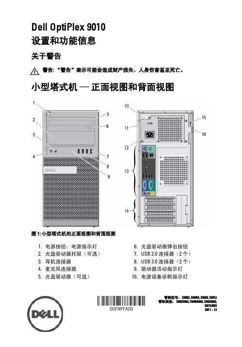
Dell OptiPlex 9010设置和功能信息关于警告警告: “警告”表示可能会造成财产损失、人身伤害甚至死亡。
小型塔式机 —正面视图和背面视图图 1: 小型塔式机的正面视图和背面视图1.电源按钮、电源指示灯2.光盘驱动器托架(可选)3.耳机连接器4.麦克风连接器5.光盘驱动器(可选)6.光盘驱动器弹出按钮B 2.0 连接器(2 个)B 3.0 连接器(2 个)9.驱动器活动指示灯10.电源设备诊断指示灯管制型号: D05D, D09M, D03S, D01U 管制类型: D05D002, D09M003, D03S002,D01U0032011 - 1211.电源设备诊断按钮12.电源连接器13.背面板连接器14.扩充卡插槽(4 个)15.安全缆线插槽16.挂锁扣环台式机 —正面视图和背面视图图 2: 台式机的正面视图和背面视图1.光盘驱动器2.光盘驱动器弹出按钮3.电源按钮、电源指示灯B 2.0 连接器(2 个)B 3.0 连接器(2 个)6.麦克风连接器7.耳机连接器8.驱动器活动指示灯9.挂锁扣环10.安全缆线插槽11.电源连接器12.背面板连接器13.扩充卡插槽(4 个)14.电源设备诊断指示灯215.电源设备诊断按钮小型塔式机和台式机 —背面板视图图 3: 小型塔式机和台式机的背面板视图1.鼠标连接器2.网络链路完整性指示灯3.网络连接器4.网络活动指示灯B 2.0 连接器(2 个)6.串行连接器7.输出连接器8.键盘连接器B 2.0 连接器(2 个)10.DisplayPort 连接器(2 个)B 3.0 连接器(2 个)12.VGA 连接器13.输入/麦克风连接器3小型计算机 —正面视图和背面视图图 4: 小型计算机的正面视图和背面视图1.光盘驱动器2.光盘驱动器弹出按钮3.电源按钮、电源指示灯B 2.0 连接器(2 个)B 3.0 连接器(2 个)6.麦克风连接器7.耳机连接器8.驱动器活动指示灯9.挂锁扣环10.安全缆线插槽11.电源连接器12.电源设备诊断按钮13.电源设备诊断指示灯14.背面板连接器15.扩充卡插槽(2 个)4小型计算机 —背面板视图图 5: 小型计算机的背面板视图1.鼠标连接器2.串行连接器3.链路完整性指示灯4.网络连接器5.网络活动指示灯B 2.0 连接器(2 个)7.输出连接器8.键盘连接器9.VGA 连接器10.DisplayPort 连接器(2 个)B 2.0 连接器(2 个)B 3.0 连接器(2 个)13.输入/麦克风连接器5超小型计算机 —正面视图和背面视图图 6: 超小型计算机的正面视图和背面视图1.光盘驱动器2.光盘驱动器弹出按钮3.电源按钮、电源指示灯4.驱动器活动指示灯5.耳机连接器6.麦克风连接器B 3.0 连接器(2 个)8.Wi-Fi 天线(可选)9.网络活动指示灯10.固定指旋螺钉11.挂锁扣环12.安全缆线插槽13.电源连接器14.输出连接器15.输入/麦克风连接器16.VGA 连接器17.DisplayPort 连接器(2 个)18.串行连接器B 3.0 连接器(2 个)B 2.0 连接器(2 个)21.网络连接器22.链路完整性指示灯6快速安装警告: 开始执行本节中的任何步骤之前,请阅读计算机附带的安全信息。
DELL optiplex-9010用户手册
目录
注、小心和警告...........................................................................................................................2
章 1. 拆装计算机...........................................................................................................................5
© 2012 Dell Inc. 本文中使用的商标: Dell™、 DELL 徽标、 Dell Precision™、 Precision ON™、ExpressCharge™、 Latitude™、Latitude ON™、 OptiPlex™、 Vostro™ 和 Wi-Fi Catcher™ 是 Dell Inc. 的商标。 Intel®、 Pentium®、 Xeon®、 Core™、 Atom™、 Centrino® 和 Celeron® 是 Intel Corporation 在美国和/或其他国家或地区的注册商标。 AMD® 是注册商标, AMD Opteron™、 AMD Phenom™、 AMD Sempron™、 AMD Athlon™、 ATI Radeon™ 和 ATI FirePro™ 是 Advanced Micro Devices, Inc. 的商标。 Microsoft®、 Windows®、 MS-DOS®、 Windows Vista®、Windows Vista 开始按钮和 Office Outlook® 是 Microsoft Corporation 在美国和/或其他 国家或地区的注册商标。 Blu-ray Disc™ 是 Blu-ray Disc Association (BDA) 拥有的商标,经其许可在磁盘和播放器上使用。 Bluetooth® 文字标记是 Bluetooth® SIG, Inc. 拥有的注册商标,Dell Inc. 经其许可使用这些标记。 Wi-Fi® 是 Wireless Ethernet Compatibility Alliance, Inc. 的注册商标。 2012 – 06 Rev. A00
《Optiplex9010(配置参数模板)》
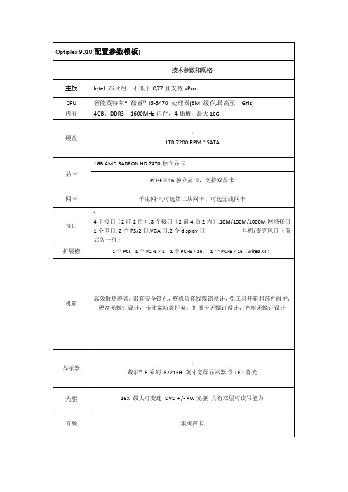
网卡
千兆网卡,可选第二块网卡、可选无线网卡
接口
#
4个接口(2前2后),8个接口(2前4后2内),10M/100M/1000M网络接口 1个串口, 2个PS/2口,VGA口,2个display口 耳机/麦克风口(前后各一组)
扩ห้องสมุดไป่ตู้槽
1个PCI,1个PCI-E×1,1个PCI-E×16, 1个PCI-E×16(wired X4)
Optiplex9010(配置参数模板)
技术参数和规格
主板
Intel 芯片组,不低于Q77且支持vPro
CPU
智能英特尔® 酷睿™ i5-3470 处理器(6M 缓存,最高至 GHz)
内存
4GB,DDR3 1600MHz内存,4插槽,最大16G
硬盘
]
1TB 7200 RPM " SATA
显卡
1GB AMD RADEON HD 7470独立显卡
机箱
高效散热静音,带有安全锁孔,整机防盗线缆锁设计,免工具开箱和部件维护,硬盘无螺钉设计,带硬盘防震托架,扩展卡无螺钉设计,光驱无螺钉设计
显示器
}
戴尔™ E系列 E2213H 英寸宽屏显示器,含LED背光
光驱
16X 最大可变速 DVD + /- RW光驱 具有双层可读写能力
音频
集成声卡
键鼠
USB 激光6键鼠标和键盘
操作系统
Windows® 7 专业版 32位(简体中文)
服务
。
3年专业技术支持: 下一工作日上门服务
认证
中国节能产品认证证书;中国环境标志产品认证证书;