TINA TI快速指南(中文)
tina入门中文版

1.h TI webpage ed TINA-TI version are:000/XPA–August 2007–RevisedAugust 2008Submit Documentation FeedbackZHCU008 –2007年8月–2008年8月修订TINA-TI™入门 1提交文档反1Overview This quick-start user's guide presents an overview of TINA-TI™,a powerful circuit design and simulation tool.TINA-TI is ideal for designing,testing,and troubleshooting a broad variety of basic and advanced circuits,including complex architectures,without any node or number of device limitations.This documentis intended to help new TINA-TI users start creating circuit simulations using the fundamental features of TINA-TI software in the shortest possible time.Contents 1Overview ......................................................................................................................12Schematic Editor .............................................................................................................23Building a Circuit with TINA-TI .............................................................................................34Analysis Capabilities ........................................................................................................65Test and Measurement .....................................................................................................96AdditionalAssistance ......................................................................................................10List of Figures 1DownloadingTINA-TI (2)2TINA-TI Schematic Editor Display .........................................................................................33Building a Circuit with TINA-TI .............................................................................................44Active and Passive Component Selection ................................................................................55Wiring Components Together ..............................................................................................66DC Analysis with Voltages/Currents Table Displayed ..................................................................77Additional TINA .....................................................................................88Virtual Instrumentation Testing (99)Contextual Help in TINA-TI ...............................................................................................10Texas Instruments has teamed up with DesignSoft,Inc.to provide our customers with TINA-TI,a powerful circuit simulation tool that is well-suited for simulating analog and switched-mode power supply (SMPS)circuits.The tool is ideal for helping designers and engineers to develop and test circuit ideas.TI selected the TINA™simulation software over other SPICE-based simulators for its combination of powerful analysis capabilities,simple and intuitive graphics-based interface,and ease of use,allowing you to be up and running in minimal time.If you are familiar with another SPICE simulator,adapting to TINA-TI should be an easy and straighforward transition.Although TINA-TI is a limited version of more powerful DesignSoft simulation products,it easily handles surprisingly complex circuits.Texas Instruments does not warrant or support any DesignSoft product.TINA-TI is a software program developed by both TI and DesignSoft.For more information about DesignSoft,visit the DesignSoft website at .TINA-TI is a trademark of Texas Instruments and DesignSoft,Inc.TINA is a trademark of DesignSoft,Inc.Windows is a registered trademark of Microsoft Corporation.All other trademarks are the property of their respective owners.SBOU052A–August 2007–Revised August 2008Getting Started with TINA-TI™1Submit Documentation Feedback这本用户快速入门指南概要性的介绍了TINA-TI™——一个强大的电路设计及仿真工具。
TINA用户手册---中文版

1.h TI webpage ed TINA-TI version are:000/XPA–August 2007–RevisedAugust 2008Submit Documentation FeedbackZHCU008 –2007年8月–2008年8月修订TINA-TI™入门 1提交文档反1Overview This quick-start user's guide presents an overview of TINA-TI™,a powerful circuit design and simulation tool.TINA-TI is ideal for designing,testing,and troubleshooting a broad variety of basic and advanced circuits,including complex architectures,without any node or number of device limitations.This documentis intended to help new TINA-TI users start creating circuit simulations using the fundamental features of TINA-TI software in the shortest possible time.Contents 1Overview ......................................................................................................................12Schematic Editor .............................................................................................................23Building a Circuit with TINA-TI .............................................................................................34Analysis Capabilities ........................................................................................................65Test and Measurement .....................................................................................................96AdditionalAssistance ......................................................................................................10List of Figures 1DownloadingTINA-TI (2)2TINA-TI Schematic Editor Display .........................................................................................33Building a Circuit with TINA-TI .............................................................................................44Active and Passive Component Selection ................................................................................55Wiring Components Together ..............................................................................................66DC Analysis with Voltages/Currents Table Displayed ..................................................................77Additional TINA .....................................................................................88Virtual Instrumentation Testing (99)Contextual Help in TINA-TI ...............................................................................................10Texas Instruments has teamed up with DesignSoft,Inc.to provide our customers with TINA-TI,a powerful circuit simulation tool that is well-suited for simulating analog and switched-mode power supply (SMPS)circuits.The tool is ideal for helping designers and engineers to develop and test circuit ideas.TI selected the TINA™simulation software over other SPICE-based simulators for its combination of powerful analysis capabilities,simple and intuitive graphics-based interface,and ease of use,allowing you to be up and running in minimal time.If you are familiar with another SPICE simulator,adapting to TINA-TI should be an easy and straighforward transition.Although TINA-TI is a limited version of more powerful DesignSoft simulation products,it easily handles surprisingly complex circuits.Texas Instruments does not warrant or support any DesignSoft product.TINA-TI is a software program developed by both TI and DesignSoft.For more information about DesignSoft,visit the DesignSoft website at .TINA-TI is a trademark of Texas Instruments and DesignSoft,Inc.TINA is a trademark of DesignSoft,Inc.Windows is a registered trademark of Microsoft Corporation.All other trademarks are the property of their respective owners.SBOU052A–August 2007–Revised August 2008Getting Started with TINA-TI™1Submit Documentation Feedback这本用户快速入门指南概要性的介绍了TINA-TI™——一个强大的电路设计及仿真工具。
Table Top Type Robot TT 第一步指南 第二版说明书
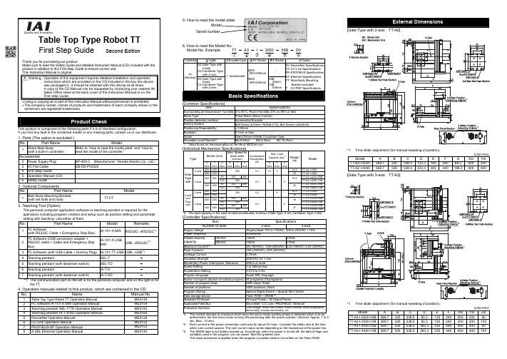
Table Top Type Robot TTFirst Step Guide Second EditionThank you for purchasing our product.Make sure to read the Safety Guide and detailed Instruction Manual (CD) included with theproduct in addition to this First Step Guide to ensure correct use.This Instruction Manual is original.• Using or copying all or part of this Instruction Manual without permission is prohibited.• The company names, names of products and trademarks of each company shown in thesentences are registered trademarks.This product is comprised of the following parts if it is of standard configuration.If you find any fault in the contained model or any missing parts, contact us or our distributor.1. Parts (The option is excluded.)No.Part Name Model1Robot Main Body(with a built-in controller)Refer to “How to read the model plate” and “How toread the model of the controller.”Accessories2 Power Supply Plug AP-400-C (Manufacturer: Yamate Electric Co., Ltd.)3 I/O Flat Cable CB-DS-PIO0204 First Step Guide5 Operation Manual (CD)6 Safety Guide2. Optional ComponentsNo.Part Name Model1Main Body Mounting Bracket(with set bolts and nuts)TT-FT3. Teaching Tool (Option)The personal computer application software or teaching pendant is required for theoperations including program creation and setup such as position setting and parametersetting with teaching. Use either of them.No.Part Name Model Remarks1PC Software(with RS232C Cable + Emergency Stop Box)IA-101-X-MW RS232C→RS232C*12PC Software (USB conversion adapter +RS232C cable + Cable and Emergency StopBox)IA-101-X-USBMW USB→RS232C*13 PC Software (with USB Cable + Dummy Plug) IA-101-TT-USB USB→USB*14 Teaching pendant SEL-T -5 Teaching pendant (with deadman switch) SEL-TD -6 Teaching pendant IA-T-X -7 Teaching pendant (with deadman switch) IA-T-XD -*1 The communication port on the left is for the personal computer and on the right is forthe TT.4. Operation manuals related to this product, which are contained in the CD. Manual No.1 Table Top Type Robot TT Operation Manual ME01492 PC software IA-101-X-MW Operation Manual ME01543 Teaching pendant SEL-T/TD Operation Manual ME01834 Teaching pendant IA-T-X/XD Operation Manual ME01605 DeviceNet Operation Manual ME01246 CC-Link Operation Manual ME01237 PROFIBUS-DPOperationManual ME01538 X-SEL Ethernet Operation Manual ME01406. How to read the Model No.Model No. Example TT - A3 -I - 2020 - 05B - DV①②③④⑤⑥①Series②Type③Encoder type④XY Stroke⑤Z Stroke⑥OptionA2:Gate Type with2-axisC2:Cantilever Typewith 2-axis-TT(Normal) A3:Gate Type with3-axisC3:Cantilever Typewith 2-axisI: Incremental2020200×200mm4040400×400mm05B50mm10B100mmDV :DeviceNet SpecificationsCC :CC-Link SpecificationsPR :PROFIBUS SpecificationsET :Ethernet SpecificationsFT :Main Body MountingBracket includedP :I/O PNP SpecificationsBasic Specifications[Common Specifications]Item SpecificationsSurrounding air temperature・humidity0 to 40°C, Room Humidity 20% to 85% or lessMotor Type Pulse Motor (Servo Control)Position detection method Incremental EncoderDriving System Ball Screw (φ10mm, Rolled C10), Ball Screw Lead 6mmPositioning Repeatability± 0.02mmBacklash 0.1mm or lessGuide Direct Driven Infinite Circulation TypeAllowable Load Moment*1Ma:6•5N•m Mb:9.3N•m Mc:16.4N•m*1 Value found on the assumption of the life of 5000 km run[Individual Mechanism Specifications]Stroke (mm)Max. Speed foreach axes(mm/sec)Max. LoadCapacity(kg)*2TypeXAxisYAxisZAxisXAxisYAxisZAxisAcceleration/Deceleration(G) XAxisYAxisZAxisWeight(kg)Model200 200- 14.8 TT-A2-I-20202-axis400 400-300 0.310 5-33 TT-A2-I-404050300 280TT-A3-I-2020-05B200 20010030016.5TT-A3-I-2020-10B50300 280TT-A3-I-4040-05BGateTypewith 3-axis400 4001003000.3 10- 235TT-A3-I-4040-10B200 200- 16.3 TT-C2-I-20202-axis400 400-300 0.2-4-35 TT-C2-I-404050300 280TT-C3-I-2020-05B200 20010030018TT-C3-I-2020-10B50300 280TT-C3-I-4040-05BCantileverTypewith 3-axis400 4001003000.2 --237TT-C3-I-4040-10B*2 The load capacity in the case of rated acceleration is shown (Gate Type: 0.3G, Cantilever Type: 0.2G)[Controller Specifications]Item SpecificationsNumber of axes 2-axis 3-axisSupply voltage Single-phase 100 to 115VAC, 200 to 230VAC ± 10%Power frequency50Hz/60Hz100VAC 150VA 210VAPower-sourcecapacity 200VAC 155VA 215VAMaximum Current*33A (100VAC), 1.6A (200VAC) 4.2A (100VAC), 2.2A (200VAC)Rush Current*415A (100VAC), 30A (200VAC)Leakage Current0.75mAInsulation Strength 2000VAC for 1 min.Momentary Power Interruption Tolerance500μs or moreSpeed Setting 1 to 300mm/secAcceleration Setting0.01G to 0.3GProgram language Super SEL languageNumber of programs (Number of multitask programs)64 programs (16 programs)Number of program steps 6000 steps (Total)Number of positions 3000 positions (Total)Program Startup Special Digital Switch + Special Start SwitchData storage device Flash ROM + SRAM*5Standard I/O Board 16 Input Points / 16 Output PointsApplicable Field Bus DeviceNet / CC-Link / PROFIBUS / EthernetProtective functions Over-voltage, motor over current, motor overload, driver temperatureabnormality, encoder abnormality, etc.*3 The current reaches its maximum level when the servo-motor exciting phase is detected which is to beperformed in the first servo-motor turning ON processing after the power injection. (Normal: Approx. 1 to 2sec, Max.: 10 sec)*4 Rush current at the power connection continues for about 20 msec. Consider the safety rate at the timewhen rush current passes. The rush current value varies depending on the impedance of the power line.*5 The SRAM data is not battery backed up. Accordingly, when the power is turned off, the data of flags andvariables used in the program, are not saved. Take the greatest care.The same procedure is applied when the program or position data is not written on the Flash ROM.External Dimensions[Gate Type with 2-axis TT-A2]*1 Fine slider adjustment (for manual tweaking of position).(Unit mm)Model A B C DEFGXstYstTT-A2-I-2020 369.7 330 338.5 133.318524088.2200200TT-A2-I-4040 569.7 530 538.5 333.3385440188.2400400[Gate Type with 3-axis TT-A3]*1 Fine slider adjustment (for manual tweaking of position).(Unit mm)Model ABCDEFXst Yst ZstTT-A3-I-2020-05B 369.7 330 338.5 83.313524020020050TT-A3-I-2020-10B 369.7 330 338.5 83.3135240200200100TT-A3-I-4040-05B 569.7 530 538.5 283.333544040040050TT-A3-I-4040-10B 569.7 530 538.5 283.3335440400400100 Warning : Operation of this equipment requires detailed installation and operationinstructions which are provided on the CD included in the box this devicewas packaged in. It should be retained with this device at all times.A copy of the CD Manual can be requested by contacting your nearest IAISales Office listed at the back cover of the Instruction Manual or on theFirst Step Guide.[Cantilever Type with 2-axis TT-C2]*1Fine slider adjustment (for manual tweaking of position).(Unit mm)Model A B C D E F XstYst TT-C2-I-2020 405 320 135 120 310 42 200 200 TT-C2-I-4040 605 520 335 213.6 510 142 400 400[Cantilever Type with 3-axis TT-C3]*1 Fine slider adjustment (for manual tweaking of position).(Unit mm)Model A B C D E F Xst Yst Zst TT-C3-I-2020-05B 405 330.6 135 120 310 71 200 200 50 TT-C3-I-2020-10B 405 330.6 135 120 310 71 200 200 100 TT-C3-I-4040-05B 605 530.6 335 213.6 510 171 400 400 50 TT-C3-I-4040-10B 605 530.6 335 213.6 510 171 400 400 100Do not use this product in the following environment:• Location where the surrounding air temperature exceeds the range of 0 to 40°C • Location where condensation occurs due to abrupt temperature changes • Relative humidity less than 20%RM or greater than 85%RM • Location exposed to corrosive gases or combustible gases• Location exposed to significant amount of dust, salt or iron powder • Location subject to direct vibration or impact • Location exposed to direct sunlight• Location where the product may come in contact with water, oil or chemical dropletsWhen using the product in any of the locations specified below, provide a sufficient shield.• Location subject to electrostatic noise• Location where high electrical or magnetic field is present • Location with the mains or power lines passing nearbyInstallation and Noise Elimination1. There is a cooling vent hole on the main body’s rear panel section. Do not close the vent hole when the main body is installed.2. When it required to fix the main body, fix it as follows using the optional mounting brackets3. Protective Ground4. Noise Elimination Grounding (Frame Ground)Connect it using a soft copper wire with the diameter of 1.6 mm or more to the frame ground on the main body (Refer to the above figure).Do not share the ground wire with or connect to other equipment. Ground each controller. The same procedure is applied for the protective ground.5. Precautions Regarding wiring Method6. Noise Sources and EliminationCarry out noise elimination measures for power devices on the same power path and in the same equipment. The following are examples of measures to eliminate noise sources:①AC solenoid valves, magnet switches and relays [Measure] Install a Noise killer parallel with thecoil.②DC solenoid valves, magnet switches and relays [Measure] Install a diode parallel with the coil.Use a DC relay with a built-in diode.Table Top TTTable Top TTOther equipmentOther equipment Other equipment+24V 0V4-M4 Depth 82- φ 4H7 Depth 5(Cable Projection Length)7.34.34.31.837.430304250Z-Slider Set Hole Section4-M5 Depth 10T-Groove SectionRear Panel Section*1 For the selection of the circuit breaker, perform it according to the following items.Breaker Teaching pendant Value > Power Capacity ÷ AC Input Voltage(Refer to the item for the controller specifications for the power capacity).•The current reaches the maximum level when the servo-motor is turned on and theservo-motor exciting phase is detected. Select the circuit breaker rated current thatdoes not trip the maximum current.• Select the circuit breaker that does no trip with the rush current described in thecontroller specifications.(Refer to the operating characteristic curve described in the manufacturer’s catalog.)• For the rated breaking current for the circuit breaker, select the breaking current valuewith which the current can be securely broken down even when short-circuit currentpasses.Rated Breaking Current > Short-circuit Current = Primary Power SupplyCapacity/Power Voltage.• Select the breaking current value for the circuit breaker leaving some margin.*2When the leakage breaker is to be installed, it is required to select it with the purposeclarified such as protection from fire or human body protection.Measure the leakage current at the location where the leakage breaker has beeninstalled.Use the “applicable to higher harmonics type” leakage breaker.Input*1Set the input functions using the I/O parameter Nos. 30 to 45 (Input Function Selection 000 to 015) and set the port Nos.that assign the each of the set functions, using the I/O parameter Nos. 282 to 298.*2If the input function selection 000 (program start) is assigned to any port except for the Port No. 000, the start switch onthe front panel is disabled.*3When the input function selection 007 to 013 (program No. designating digital switch) are assigned to any port except forthe port Nos. 007 to 013, the program change digital switch on the front panel is disabled.Output*4Set the output functions using the I/O parameter Nos. 46 to 61 (Output Function Selection 300 to 315) and set the portNos. that assign the each of the set functions, using the I/O parameter Nos. 299 to 314. Also, setting the output functionsusing the I/O parameter Nos. 331 to 346 (Output Function Selection 300 Area 2 to 315 Area 2) and setting the Port Nos.that assign the each of the set functions, using the I/O parameter Nos. 315 to 330, are available.When the system output signal is output to the I/Os on the above table, use the Output Function Selection Area 2.*5Because the output function selections 300 to 304 are allocated to the LEDs on the panel window, when the parameters of46 to 50 are set to universal output, or the Port No. allocation is changed using the parameter 299 to 303 settings, theLEDs are disabled.I/O Flat Cable (Accessories) CB-DS-PIO020No.Color Wirings No.Color Wirings1BR118GY22RD 119WT 23OR120BK24YW121BR35GN 122RD 36BL123OR37PL124YW38GY125GN39WT126BL310BK 127PL 311BR 228GY 312RD 229WT 313OR 230BK 314YW 231BR 415GN 232RD 416BL 233OR 417PL 2Flat cable(Presswelding)34YW 4Flat cable(Presswelding)I/O Circuit DiagramsNPN Specifications PNP SpecificationsPinNo.ElectricwirecolorPortNo.Function inStandardSetting(in Delivery)1 BR1 -I/O PowerSource +24V2 RD1 016UniversalInput3 OR1 017UniversalInput4 YW1 018UniversalInput5 GN1 019UniversalInput6 BL1 020UniversalInput7 PL1 021UniversalInput8 GY1 022UniversalInput9 WT1 023UniversalInput10 BK1 024UniversalInput11 BR2 025UniversalInput12 RD2 026UniversalInput13 OR2 027UniversalInput14 YW2 028UniversalInput15 GN2 029UniversalInput16 BL2 030UniversalInput17 PL2 031UniversalInputRemarksIt is set to the universal input when it is delivered. However, the change of the inputfunction is available with the I/O parameter setting.Parameter*1No. Parameter Name Remarks30 Input function select 000*21: Program Start31 Input function select 001 0: Universal Input1: Software Reset32 Input function select 002 0: Universal Input1: Servo ON signal33 Input function select 003 0: Universal Input1: Program automatically started when the power ON is reset inAUTO mode and software is reset2: Automatic Starting Program Signal34 Input function select 004 0: Universal Input1: All servo-axes soft interlock (OFF level)35 Input function select 005 0: Universal Input1: Pause Release (ON edge)36 Input function select 006 0: Universal Input1: Pause Signal (OFF level)37 Input function select 007*30: Universal Input1: Program No. appointment (LSB)38 Input function select 008*30: Universal Input1: Program No. appointment(The second bit)39 Input function select 009*30: Universal Input1: Program No. appointment(The third bit)40 Input function select 010*30: Universal Input1: Program No. appointment(The fourth bit)41 Input function select 011*30: Universal Input1: Program No. appointment(The fifth bit)42 Input function select 012*30: Universal Input1: Program No. appointment(The sixth bit)43 Input function select 013*30: Universal Input1: Program No. appointment(MSB : The seventh bit)2: Error Reset(ON edge)44 Input function select 014 0: Universal Input1: Driving Power Interruption Cancellation Input (ON Edge)45 Input function select 015 0: Universal Input1: All Effective Axes Homing (ON Edge)2: All Increment Effective Axes Homing (ON Edge)PinNo.ElectricwirecolorPortNo.Function inStandardSetting(in Delivery)18 GY2 316UniversalOutput19 WT2 317UniversalOutput20 BK2 318UniversalOutput21 BR3 319UniversalOutput22 RD3 320UniversalOutput23 OR3 321UniversalOutput24 YW3 322UniversalOutput25 GN3 323UniversalOutput26 BL3 324UniversalOutput27 PL3 325UniversalOutput28 GY3 326UniversalOutput29 WT3 327UniversalOutput30 BK3 328UniversalOutput31 BR4 329UniversalOutput32 RD4 330UniversalOutput33 OR4 331UniversalOutput34 YW4 -I/O PowerSource 0VRemarksIt is set to the universal output when it is delivered. However, the change of the outputfunction is available with the parameter setting.Parameter*4No. Parameter Name Function46331Output function select 300*5Output function select 300(Area 2)0: Universal Output1: Error Output at the operation cancellation level or more (ON)2: Error Output at the operation cancellation level or more (OFF)3: Error Output at the operation cancellation level or more +emergency stop output (ON)4: Error Output at the operation cancellation level or more +emergency stop output (OFF)47332Output function select 301*5Output function select 301(Area 2)0: Universal Output1: READY Output (PIO Trigger Program Operation Available)2: READY Output (PIO Trigger Program Operation Available)and without occurrence of any error at the operationcancellation level or more3: READY Output (PIO Trigger Program Operation Available)and READY Output (PIO Trigger Program OperationAvailable, and without occurrence of any error at the cold startlevel or more or more level or more48333Output function select 302*5Output function select 302(Area 2)0: Universal Output1: Emergency-stop output(ON)2: Emergency-stop output(OFF)49334Output function select 303*5Output function select 303(Area 2)0: Universal Output1: AUTO Mode Output2: Output during the Automatic Operation (In addition, when theparameter No. 12 is set to “1”)50335Output function select 304*5Output function select 304(Area 2)0: Universal Output1: Output at the time of “All Effective Axes Homing (=0)”2: Output when all the effective axes homing is completed3: Output when all the effective axes home preset coordinatesare set51336Output function select 305Output function select 305(Area 2)0: Universal Output2: Output during the first axis servo ON52337Output function select 306Output function select 306(Area 2)0: Universal Output2: Output during the second axis servo ON53338Output function select 307Output function select 307(Area 2)0: Universal Output2: Output during the third axis servo ON54339Output function select 308Output function select 308(Area 2)0: Universal Output55340Output function select 309Output function select 309(Area 2)0: Universal Output56341Output function select 310Output function select 310(Area 2)0: Universal Output57342Output function select 311Output function select 311(Area 2)0: Universal Output58343Output function select 312Output function select 312(Area 2)0: Universal Output59344Output function select 313Output function select 313(Area 2)0: Universal Output60345Output function select 314Output function select 314(Area 2)0: Universal Output61346Output function select 315Output function select 315(Area 2)0: Universal OutputWhen using this product for the first time, make sure to avoid mistakes and incorrect wiring by referring to the procedure below.Set-up for operation is completed.TroubleshootingThe following alarm displays are frequently generated at the start-up operation.Head Office: 577-1 Obane Shimizu-KU Shizuoka City Shizuoka 424-0103, JapanTEL +81-54-364-5105 FAX +81-54-364-2589website: www.iai-robot.co.jp/Ober der Röth 4, D-65824 Schwalbach am Taunus, GermanyTEL 06196-88950 FAX 06196-889524SHANGHAI JIAHUA BUSINESS CENTER A8-303, 808, Hongqiao Rd. Shanghai 200030, ChinaTEL 021-6448-4753 FAX 021-6448-3992website: Technical Support available in USA, Europe and ChinaHead Office: 2690 W. 237th Street, Torrance, CA 90505TEL (310) 891-6015 FAX (310) 891-0815Chicago Office: 110 East State Parkway, Schaumburg, IL 60173TEL(847) 908-1400 FAX (847) 908-1399TEL (678) 354-9470 FAX (678) 354-9471website: Atlanta Office: 1220 Kennestone Circle, Suite 108, Marietta, GA 30066825 PhairojKijja Tower 12th Floor, Bangna-Trad RD., Bangna, Bangna, Bangkok 10260, ThailandTEL +66-2-361-4458 FAX +66-2-361-4456Manual No.: ME0205-2D。
介绍一种滤波器电路设计的简易方法
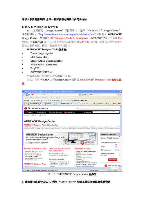
南华大学黄智伟系列介绍一种滤波器电路设计的简易方法1. 进入TI WEBENCH设计中心在TI主界面的“Design Support”下拉菜单中,选择“WEBENCH® Design Center”,或者按照网址―/ww/en/analog/webench/index.shtml‖可以进入WEBENCH®Design Center WEBENCH® Designer Tools & Eco-System(WEBENCH®设计工具和Eco 系统)。
WEBENCH设计工具具有功能强大的软件算法和可视化界面,能够在几秒钟为用户提供完整的电源,照明,传感器等应用设计。
WEBENCH® Designer Tools包含有:∙Power (single supply)∙LED (enter LED)∙Sensor AFE & Sensor Interface∙Active Filters | Amplifiers∙EasyPLL∙All WEBENCH Tools单击各选项,可以进入对应的设计工具。
注意:使用WEBENCH® Design Center提供的WEBENCH® Designer Tools需要先注册。
图1.1.1 WEBENCH® Design Center主界面2. 滤波器电路设计方法1:利用“Active Filters”设计工具进行滤波器电路设计2.1进入“WEBENCH® Active Filter Designer”单击“Active Filters | Amplifiers”的“Active Filters”,进入“WEBENCH® Active Filter Designer”,在所显示的界面中,在图2.1.1所示对话框中,可以选择设计对象:PLL,Filter,Amps。
tina使用说明
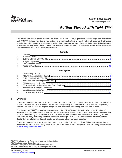
1OverviewQuick Start GuideSBOU052–August 2007This quick start user's guide presents an overview of TINA-TI™,a powerful circuit design and simulation tool.TINA-TI is ideal for designing,testing,and troubleshooting a broad variety of basic and advanced circuits,including complex architectures,without any node or number of device limitations.This document is intended to help new TINA-TI users start creating circuit simulations using the fundamental features of TINA-TI software in the shortest possible time.Contents 1Overview (12)Schematic Editor (23)Building a Circuit with TINA-TI (34)Analysis Capabilities (65)Test and Measurement .....................................................................................................96Additional Assistance (10)List of Figures1Downloading TINA-TI (22)TINA-TI Schematic Editor Display (33)Building a Circuit with TINA-TI (44)Active and Passive Component Selection (55)Wiring Components Together (66)DC Analysis with Voltages/Currents Table Displayed (77)Additional TINA Analysis Capabilities (88)Virtual Instrumentation Testing .............................................................................................99Contextual Help in TINA-TI ...............................................................................................10Texas Instruments has teamed up with DesignSoft,Inc.to provide our customers with TINA-TI,a powerful circuit simulation tool that is well-suited for simulating analog and switched-mode power supply (SMPS)circuits.The tool is ideal for helping designers and engineers to develop and test circuit ideas.TI selected the TINA™simulation software over other SPICE-based simulators for its combination of powerful analysis capabilities,simple and intuitive graphics-based interface,and ease of use,allowing you to be up and running in minimal time.If you are familiar with another SPICE simulator,adapting to TINA-TI should be an easy and straighforward transition.Although TINA-TI is a limited version of more powerful DesignSoft simulation products,it easily handles surprisingly complex circuits.Texas Instruments does not warrant or support any DesignSoft product.TINA-TI is a software program For more information about DesignSoft,visit the DesignSoft website at TINA-TI is a trademark of Texas Instruments and DesignSoft,Inc.TINA is a trademark of DesignSoft,Inc.Windows is a registered trademark of Microsoft Corporation.All other trademarks are the property of their respective owners. Schematic Editor2Schematic EditorYou can download TINA-TI as shown in Figure1.Alternatively,it is availablethrough the TI home page at the a summary of TINA-TI related information.you to theFigure1.Downloading TINA-TIThe minimum hardware and software requirements for the currently released TINA-TI version are:•IBM PC-compatible computer running Microsoft Windows®98/ME/NT/2000/XP•Pentium or equivalent processor•64MB of RAM•Hard disk drive with at least100MB free space•Mouse•VGA adapter card and monitor2Getting Started with TINA-TI™SBOU052–August20073Building a Circuit with TINA-TIBuilding a Circuit with TINA-TIOnce the software is downloaded to your system,select the program through the Windows Start menu or click on the TINA-TIicon on your desktop that was created during the installation.The first screen appears as shown in Figure 2.Figure 2.TINA-TI Schematic Editor DisplayFigure 2shows the schematic editor layout.The empty workspace on the sheet is the design windowbuild the test circuit.Below the Schematic Editor title bar is an operational menu row withselections such as file operations,analytical operations,test and measurement equipment selection,etc.Located just below the menu row is a row of icons associated with different file and TINA tasks.The final row of icons allows you to select a specific component group.These component groups contain basicpassive components,semiconductors,and even sophisticated device macromodels.These groups areaccessed to build the circuit schematic.To illustrate how easy it is to use TINA-TI,we will build an analog circuit and demonstrate some of thecircuit analysis capabilities.For this example,a high-output,1kHz sine wave oscillator circuit is selected.A search through a circuitapplication handbook provides a number of op amp-based designs.We will build and Wein-bridge oscillator with amplitude stabilization using the software.A Texas Instruments'12V CMOS op amp is selected for the circuit application.This amplifier is well-suited for this provides very good dc and ac performance.It operates with supplies of 3.5V to 12V;our example requires ±5V (10V). Building a Circuit with TINA-TISelect the Spice Macros tab(see Figure3,step1)and then the op amp symbol(step2)to access the OPA743macromodel.When the list appears,scroll down and click on the OPA743(step3).Then click OK.The op amp symbol appears in the circuit workspace.With the mouse,drag the symbolinto position(step4).It is locked into position on the circuit workspace by clicking the left mouse button.Figure3.Building a Circuit with TINA-TIOther op amp models may be selected using the Insert->Macro...menu.Additionally,macros and a wide variety of pre-built analog and SMPS circuits can be accessed through the Insert menu.(Insert->Macro...TinaTI_7.0->Examples).4Getting Started with TINA-TI™SBOU052–August2007Building a Circuit with TINA-TI 3.1Adding Passive and Active ComponentsComponent selection is easily accomplished by clicking on a component group from the lower row of tabs: Basic,Switches,Meters,and so forth.These tabs provide a wide variety of passive components,sources, meters,relays,semiconductors,and the previously-mentioned circuit macros.Click on the schematicsymbol for a particular component and drag it into position in the circuit workspace.A left mouse button click locks it into place.In our example,shown in Figure4,we select a resistor from the Basic tab group(step1and step2),then position it next to the op TINA-TI designates this resistor as R1.The initial value of R1is1kΩ,but this value can be changed as needed.A double-click with the left mouse button on the R1symbol produces the associated component table(step3).Figure4.Active and Passive Component SelectionThe resistor value and other component characteristics may be altered by selecting the individualparameter boxes and changing the respective values.Select the component parameter box and highlight the value you wish to change.Enter a new value by typing over the value that is shown.In Figure4,for example,the value for R1has been changed from1k to4.7k for this circuit.Once yousetting the parameters,click OK to close the table.Similar parametric tables are available for passivedevices,sources,semiconductors,and other component types.A handy component that is displayed in the Basic group is the jumper,as shown in Figure4.It looks like asideways letter T.The jumper may be used to connect similar,related circuit as V+,V–,or any other circuit point that has multiple ing the jumper reduces wiring clutter.Note that common jumpers must be labeled with the same label name for TINA-TI to connect them together.3.2Arranging and WiringComponents4Analysis CapabilitiesAnalysis CapabilitiesOnce all components are selected and properly positioned,they can be wired together.Each component has nodes where circuit connections are needed.TINA displays these nodes with a small red x .(The x looks more like two small lines at the wiring node than the alpha character.)Wiring components to each other is easily done by placing the mouse pointer over a node connection and holding the left mousebutton down.A wire is drawn as the mouse is moved along the circuit space grid.Release the mousebutton when the wire reaches the intended end connection point.Figure 5illustrates the TINA-TI software wiring function.Figure 5.Wiring Components TogetherThe wiring function also may be accessed from the Insert menu,or the icon that looks like a small pencil.When the circuit schematic entry is complete,the circuit is nearly ready for simulation.The analysisprocess begins by selecting the Analysis menu.A list of different types of analyses—such as ac,dc,transient,or noise—appears.Highlight any one of these evaluations to access additional options andselections.The first option under the Analysis menu is an Error Rules Check (ERC).Selecting this feature runs this check on the circuit;a pop-up window then lists any circuit errors.If an error is listed in the window,clicking on that error line highlights the error point in the schematic.The error window also lists other types of circuit errors that are found during the analysis.6Getting Started with TINA-TI™SBOU052–August 20074.1DCAnalysisAnalysis CapabilitiesEven if the ERC is not selected,TINA automatically performs a check at the start of a simulation.Upon selecting one type of analysis to perform,another window appears that displays different settingselections that are associated with that particular analysis.Nominal settings are initially provided;theseparameters may be set as needed for the desired output.Once all of the selections are made,click OK to begin the analysis.The first analysis performed on acircuit is generally a dc analysis.This test provides a reality check so that normal dc operating conditions can be verified.The TINA-TI DC Analysis function can be set to calculate nodal voltages,provide a table of dc voltage and current results,generate a dc sweep of the circuit,or perform a temperature analysis.The temperature analysis works in combination with the Analysis >Mode >temperature-steppingselections.Follow these steps (illustrated in Figure 6)to perform a dc analysis.1.Click on the Analysis menu.2.Select DC Analysis .3.Click on Table of DC Results .The Voltages/Currents table appears.e the mouse pointer as a probe to test the circuit nodes.The probed node and measured value are displayed in red in the Voltages/Currents table,as shown inFigure 6.Figure 6.DC Analysis with Voltages/Currents Table Displayed Analysis Capabilities4.2Transient AnalysisSophisticated ac frequency and time domain simulations may also be e the Analysisfunction to access the different choices.A traditional ac transfer characteristic plot of gain and phaseversus frequency may be selected,as well as transient,Fourier or noise analyses.The example shown in Figure7is a transient analysis performed on the example Wein-bridge oscillator circuit.The simulation analysis result is also shown in Figure7.It illustrates the Wein-bridge oscillator startup and steady-state performance.The display in window may be edited with axis labeling,scales,background grid color,and so forth,all set as desired by the individual user.Follow these steps(marked in Figure7)to perform a transient analysis.1.Click on the Analysis menu.2.Select Transient.3.The Transient Analysis dialog box appears.Enter start and end times,and other parameters asdesired.4.Click OK to run the analysis.Figure7.Additional TINA Analysis Capabilities8SBOU052–August2007 Getting Started with TINA-TI™Test and Measurement 5Test and MeasurementThe TINA-TI software generates post-simulation results in tables and plots,depending on the type ofanalysis performed.Additionally,the software can be placed in a pseudo-real-time simulation mode where virtual instruments can be used to observe the output(s)while the circuit is operating.For example,Figure8shows a virtual oscilloscope that is used to observe the steady-state output of the Wein-bridge circuit.In the same way,a virtual signal analyzer can be used together with anamplifier circuit so that the harmonic performance of a simulation can be observed.To access the virtual oscilloscope,select T&M(step1in Figure8),and then Oscilloscope(step2).Place the cursor at theoutput of the simulated circuit,and controls in the virtual oscilloscope dialog box as needed(step3).The T&M selection options also include a virtual ac/dc multimeter,function generator,and an X-Yrecorder.The function generator may be adjusted in combination with a virtual oscilloscope or analyzer.Figure8.Virtual Instrumentation Testing Additional Assistance6Additional AssistanceTINA-TI has many more features that can be explored.As you become more comfortable with thesimulation software,you will be able to take advantage of these capabilities to build circuits more rapidly, perform more sophisticated simulations,and optimize the output information for a variety of needs.The software also offers on-screen contextual help,and displays mouse-over descriptions for many icons and areas of the workspace,as shown in Figure9.If you need additional assistance with a particularanalysis,or help with setting the active parameters,detailed help documentation is available.Click on the Help menu to access information associated with circuit analysis,active components,and so forth.Further assistance for specific TINA-TI application simulations is available by contacting your local TI technical representative.Figure9.Contextual Help in TINA-TINote:Texas Instruments does not offer support for TINA software.Contact youhave questions or need assistance with general TINA software10Getting Started with TINA-TI™SBOU052–August2007IMPORTANT NOTICETexas Instruments Incorporated and its subsidiaries(TI)reserve the right to make corrections,modifications,enhancements,improvements, and other changes to its products and services at any time and to discontinue any product or service without notice.Customers should obtain the latest relevant information before placing orders and should verify that such information is current and complete.All products are sold subject to TI’s terms and conditions of sale supplied at the time of order acknowledgment.TI warrants performance of its hardware products to the specifications applicable at the time of sale in accordance with TI’s standard warranty.Testing and other quality control techniques are used to the extent TI deems necessary to support this warranty.Except where mandated by government requirements,testing of all parameters of each product is not necessarily performed.TI assumes no liability for applications assistance or customer product design.Customers are responsible for their products and applications using TI components.To minimize the risks associated with customer products and applications,customers should provide adequate design and operating safeguards.TI does not warrant or represent that any license,either express or implied,is granted under any TI patent right,copyright,mask work right, or other TI intellectual property right relating to any combination,machine,or process in which TI products or services are rmation published by TI regarding third-party products or services does not constitute a license from TI to use such products or services or a warranty or endorsement e of such information may require a license from a third party under the patents or other intellectual property of the third party,or a license from TI under the patents or other intellectual property of TI.Reproduction of TI information in TI data books or data sheets is permissible only if reproduction is without alteration and is accompanied by all associated warranties,conditions,limitations,and notices.Reproduction of this information with alteration is an unfair and deceptive business practice.TI is not responsible or liable for such altered rmation of third parties may be subject to additional restrictions.Resale of TI products or services with statements different from or beyond the parameters stated by TI for that product or service voids all express and any implied warranties for the associated TI product or service and is an unfair and deceptive business practice.TI is not responsible or liable for any such statements.TI products are not authorized for use in safety-critical applications(such as life support)where a failure of the TI product would reasonably be expected to cause severe personal injury or death,unless officers of the parties have executed an agreement specifically governing such use.Buyers represent that they have all necessary expertise in the safety and regulatory ramifications of their applications,and acknowledge and agree that they are solely responsible for all legal,regulatory and safety-related requirements concerning their products and any use of TI products in such safety-critical applications,notwithstanding any applications-related information or support that may be provided by TI.Further,Buyers must fully indemnify TI and its representatives against any damages arising out of the use of TI products in such safety-critical applications.TI products are neither designed nor intended for use in military/aerospace applications or environments unless the TI products are specifically designated by TI as military-grade or"enhanced plastic."Only products designated by TI as military-grade meet military specifications.Buyers acknowledge and agree that any such use of TI products which TI has not designated as military-grade is solely at the Buyer's risk,and that they are solely responsible for compliance with all legal and regulatory requirements in connection with such use. TI products are neither designed nor intended for use in automotive applications or environments unless the specific TI products are designated by TI as compliant with ISO/TS16949requirements.Buyers acknowledge and agree that,if they use any non-designated products in automotive applications,TI will not be responsible for any failure to meet such requirements.Following are URLs where you can obtain information on other Texas Instruments products and application solutions:Products ApplicationsAmplifiers AudioData Converters AutomotiveDSP BroadbandInterface Digital ControlLogic MilitaryPower Mgmt Optical NetworkingMicrocontrollers SecurityRFID TelephonyLow Power Wireless Video&ImagingWirelessMailing Address:Texas Instruments,Post Office Box655303,Dallas,Texas75265Copyright©2007,Texas Instruments Incorporated。
TINA-TI模拟电路设计仿真和分析软件
打开并编辑所选的宏元件。电路图宏用编辑器打开,Pspice 宏用网表编辑器打开。 修改电路图中元件的属性与参数。 用原理图符号编辑器修改元件原理图符号。 用于放置或删除一个连接点。 重复放置上一次放置的元件。快捷键为【Crtl+Ins】 。 绘制电连接线。快捷键为【空格】 。可用【Esc】键终止连线方式。 定义一个输入端。 定义一个输出端。 在电路图和分析结果中插入注释。快捷键为【Crtl+T】。 在原理图中插入图形文件。 在原理图中添加标题块。 可通过编辑默认标题块 TITLEBLK.TBT 来自定义标题块。 插入*.TSM 宏(子电路)的外形文件。 插入分层模块。 自动重复插入相同的元件, (直到按下【Esc】键或开始另一个命令。 自动重新连接所有必要的电线以保持元件的电气线路连接。 在电路图编辑器窗口中不显示页边和页边距。 按照纸张幅面显示电路图。可通过【文件|页面】命令进行设置。 打开或关闭元件末端引脚的标记。 打开或关闭元件主要参数的显示。例如:电阻器是电阻、三极管型号等。 打开或关闭主参数单位的显示。例如:电容、电感、电阻、信号源等的主参数单位。 打开或关闭元件标签的显示。 打开或关闭元件的容差 打开或关闭已设置元件管脚图封装名称属性的封装编号的显示。 刷新已绘制的原理图。快捷键为【F5】 。 打开或关闭工具栏 打开或关闭元件栏 设置:元件符号集、测量单位、交流基本函数、参数名称、自动保存间隔等。 运行电气规则检查,可在原理图编辑器中高亮显示故障点。 选择当前分析的模式。模式包括单步、参数分级、温度分级等。 指定优化参数所属的元件,显示该元件的所有相关参数。 修改一些对分析有影响的参数。 直流分析:计算节点电压、直流结果表、传输特性、温度分析等。 交流分析:计算节点电压、交流结果表、交流传输特性等。 分析电路在信号源激励下的暂态响应。 电路的稳态求解。 通过计算输出时间函数的傅立叶级数,谐波失真按百分比%单位显示。 计算电路元件产生的噪声在输出端呈现的结果。 控制 TINA 在执行所要求的分析选项及设置 ERC 规则。 多功能函数发生器。可作为参考源、 函数发生器及扫描发生器使用。
TINA-TI基本教程
TINA-TI基本教程内容简介本教程介绍了一个强大的电路设计和仿真工具TINA-TI。
TINA-TI可用于对各种电路进行设计、测试和故障诊断。
这些电路可以是简单的或者高级的具有复杂结构的电路,TINA-TI对它们没有任何节点或器件数量的限制。
本教程主要介绍TINA-TI软件的基本特征和电路仿真方法。
首先介绍了TINA-TI的特点及功能、软件的下载与安装,然后通过一个电路实例介绍了电路原理图编辑,通过另外一个TINA-TI提供的电路示例介绍了电路分析方法以及用虚拟仪器测量电路的方法,最后介绍了TINA-TI的其它辅助功能。
目录1 概述 (3)2 电路示例 (3)2.1 放大器和线性电路: (3)2.2 SMPS(开关式电源): (4)2.3 其它 (4)3 TINA-TI的使用 (4)3.1 下载与安装TINA-TI (4)3.2 启动TINA-TI (5)3.3 搭建电路 (6)3.3.1 电路原理 (6)3.3.2 在原理图中添加元件 (7)3.3.3 添加无源元件 (8)3.3.4 布置元件和连线 (10)3.4 分析电路 (11)3.4.1 直流分析 (13)3.4.2 瞬态分析 (15)3.4.3 交流分析 (16)3.5 测量电路 (18)3.5.1 万用表 (18)3.5.2 示波器 (19)3.5.3 信号分析仪 (19)3.5.4 函数发生器 (21)3.6 TINA-TI的其它辅助功能 (22)1 概述德州仪器公司(TI)与DesignSoft公司联合为客户提供了一个强大的电路仿真工具TINA-TI。
TINA-TI适用于对模拟电路和开关式电源(SMPS)电路的仿真,是进行电路开发与测试的理想选择。
TINA基于SPICE引擎,是一款功能强大而易于使用的电路仿真工具;而TINA-TI 则是完整功能版本的TINA,并加载了TI公司的宏模型以及无源和有源器件模型。
TI之所以选择TINA仿真软件而不是其它的基于SPICE技术的仿真器,是因为它同时具有强大的分析能力和简单直观的图形界面,并且易于使用。
7610.TINA-TI 9 仿真软件使用说明
Select Tina-TI Circuit Simulation
10
Downloading TINA-TITM
/webench
Links for TINA-TI v9 download
11
Installing TINA-TI 9
LM22678
LM22679
LM2830
LM2852
LME49830
LMH6523
LMZ10500
OPA1S2385
TLV62130
TLV803M
TPS54231
TPS54350
TPS7A1601
TPS81256
5
TINA-TITM 9: Same Look and Feel
6
TINA-TITM 9: Multi-Core Support
12
Installing TINA-TI 9
13
Installing TINA-TI 9
14
Installing TINA-TI 9
15
Installing TINA-TI 9
16
Installing TINA-TI 9
17
Downloading the Model Library
18
Downloading the Model Library
Wire – place pointer on component End node (small red “x”) and click to start wire. Unclick at desired end node.
29
Function Generators
Tina备份软件简介与安装配置手册

Tina备份软件简介与安装配置手册目录▪ 1.前言 (6)1.1.整体系统架构要求 (6)1.2.需求分析 (7)▪ 2.备份系统设计 (8)2.1.备份系统设计依据 (8)2.1.1.备份系统类型 (9)2.1.2.数据的保存时间 (10)2.1.3.备份的时间策略 (10)2.1.4.备份时间测算方法 (11)2.1.5.数据的恢复方法和恢复时间 (11)▪ 3.备份软件介绍 (11)3.1.Tina领先的技术优势 (11)3.2.Tina特点综述 (12)3.2.1.便于扩展的产品内部设计 (12)3.2.2.高速并行处理与缓存 (13)3.2.3.独创宏多路技术 (13)3.2.4.合成备份功能 (14)3.2.5.强大的数据压缩机制 (14)3.2.6.友好的集中管理界面 (15)3.2.7.基于浏览器的监控界面 (15)3.2.8.可视化的任务管理 (16)3.2.9.综合事件管理器 (17)3.2.10.日志文件的重定向功能 (17)3.2.11.同框架程序以及调度程序的集成 (18)3.2.12.安全的防火墙 (18)3.2.13.多重写和灾难恢复程序 (18)3.2.14.先进的意外事件处理策略 (19)3.2.15.严格的访问权限控制 (19)3.2.16.多级用户权限划分 (20)3.2.17.可靠的备份服务器用户保护 (20)3.2.18.多种数据存储格式 (20)3.2.19.先进的介质库管理与多卷缓冲池 (20)3.2.20.虚拟磁带库支持 (21)3.2.21.自动化带库支持 (21)3.2.22.集中/分散的存储管理 (22)3.2.23.安全的归档数据模型 (22)3.2.24.面向用户的归档数据检索 (22)3.2.25.对虚拟化支持 (23)3.2.26.重复删除数据 (25)3.2.27.复制容灾 (26)3.2.28.广泛的平台,数据库与应用软件支持 (26)3.2.29.备份管理 (26)▪ 4.备份服务器安装和配置 (27)4.1.安装前准备工作 (27)4.2.安装软件过程 (27)4.3.登陆控制台管理 (34)4.4.创建虚拟带库 (36)4.5.创建备份介质池 (38)4.6.选择需要备份的文件内容 (39)4.7.创建备份策略 (40)4.8.添加物理带库 (43)▪ 5.客户端安装与配置 (47)5.1.检查linux 系统内核和版本与安装软件一致 (47)5.2.软件安装过程 (47)5.3.添加客户端 (54)5.4.验证客户端 (55)▪ 6. CATALOG编目备份和恢复 (56)6.1.catalog备份 (56)6.2.Catalog恢复 (57)▪7.文件恢复 (59)7.1.还原和归档管理器 (59)7.2.时间导航功能 (59)7.3.恢复参数 (60)▪8. ORACLE备份和恢复 (62)8.1.准备工作 (62)8.2.修改系统环境变量 (63)8.3.重启软件服务 (64)8.4.在ORACLE中创建表 (64)8.5.创建Oracle备份应用 (64)8.6.数据库恢复 (67)8.7.检查还原的数据 (70)▪9. LANFREE备份配置 (70)NFree备份条件 (70)9.2.创建一个SAN网络 (70)9.3.添加LANFree主机 (71)▪10. VMWARE虚拟化备份 (73)10.1.启用vsphere模块 (73)10.2.创建vsphere应用 (74)10.3.vspher配置参数 (75)10.4.备份选择 (75)10.5.VMWARE CBT (76)10.6.vsphere恢复 (77)1.前言随着计算机存储信息量的不断增长,数据备份和灾难恢复成为引人关注的话题。
电路仿真软件TINAPRO6.0中文正
电路仿真软件TINAPRO6.0中文正电路仿真软件TINA PRO 6.0 中文正式版Tina Pro概况Tina Pro是重要的现代化EDA(Electronic Design Automation,即电子电路设计自动化)软件之一,用于模拟及数字电路的仿真分析。
其研发者是欧洲DesignSoft Kft.公司,目前大约流行四十多个国家,并有二十余种不同语言的版本,其中包括中文版,大约含有两万多个分立或集成电路元器件。
该软件的具体功能包括:在模拟电路分析方面,Tina Pro除了具有一般电路仿真软件通常所具备的直流分析、瞬态分析、正弦稳态分析、傅立叶分析、温度扫描、参数扫描、最坏情况及蒙特卡罗统计等仿真分析功能之外,还能先对输出电量进行指标设计,然后对电路元件的参数进行优化计算。
此外,它具有符号分析功能,即能给出时域过渡过程表达式或频域传递函数表达式;具有RF 仿真分析功能;具有绘制零、极点图、相量图、Nyquist图等重要的仿真分析功能。
在数字电路分析方面,Tina Pro支持VHDL语言;并具有BUS总线及虚拟连线等功能,这避免了电路图中元件之间连线过密,使得电路绘图界面看起来更清晰、简洁。
Tina Pro具有八种虚拟测量仪器,各仪器与元件之间采用虚拟连线。
其虚拟测试仪器(如多踪示波器)的动态演示功能,是极好的电类教学辅助工具。
Tina Pro的仿真分析结果,如波形图可方便地与电路图粘贴在界面中,对输出打印及分析资料的完整保存十分便利。
Tina Pro可以与其硬件设备Tina-Lab,即实时信号发生器、数据采集器相连接,故能将实时测量与虚拟仿真结果相比对。
这是目前所知能实现该项功能的少数实用技术产品之一。
Tina Pro具有较高的性能价格比。
它是目前所知为数不多的具有简体中文界面的成熟软件(在Help索引文件中,也用中文对于电路器件模型参数进行详细解释)。
Tina Pro是一种功能强大的电路仿真软件,不仅在工程实践中,对于电子产品的开发与研制能够发挥高效率、高精度的作用,而且将其引入各类学校电类课程的教学,会带来意想不到的教学效果。
TI 精度放大器快速开始包说明书

OPA171
Dual
MSOP-8(DGK), VSSOP-8(DCU), SO-8(D)
0.595
3
1.5
Quad
TSSOP-14(PW), SO-14(D)
Single SC70-5(DCK), SOT23-5(DBV), SO-8(D)
OPA172
Dual
VSSOP-8(DCU), SO-8(D)
0.19
3
1.5
Quad
TSSOP-14(PW)
Single
SC70-5(DCK), SOT23-5(DBV)
OPA316
Dual
SO-8(D), MSOP-8(DGK), DFN-8(DRG)
0.5
10
6
Quad
TSSOP-14(PW)
Wide-supply OPA17x family: Micro-package, microPower and RRO
TIPD128
Description This TI Verified Design implements a variety of op amps driving capacitive loads from 100 pF to 1 µF using an isolation resistor. This design can be used to drive capacitive loads such as cable shields, reference buffers, MOSFET gates, and diodes.
For datasheets and more information visit: /ampquickstartkit
TINA PRO 6.0 中文正式版
ICEM.CFD.v10.0.Linux.IA.64-ISO 1CD
ICEM CFD中文入门教材
Icem CFD 动画教程-ISO 1CD
ICEM-CFD培训资料(全) 1CD
CIMNE产品:
GID v8.0.9 1CD(几何建模和数值仿真工具。并提供结果可视化分析。可以处理在固体和结构力学,流体力学,电磁学,热传导等学科方面的数值仿真)
Fluent Icepak v4.0.8 1CD
Fluent Icepak 培训教程(中文)
Icepak v4.0 Help(帮助教程)
Fluent Mixsim v2.0.2 WINALL 1CD(针对搅拌混合问题的专用CFD软件)
Fluent Mixsim v2.0.2 LINUX 1CD
TINA PRO 6.0 中文正式版电路仿真软件
Tina Pro是重要的现代化EDA(Electronic Design Automation,即电子电路设计自动化)软件之一,用于模拟及数字电路的仿真分析。其研发者是欧洲DesignSoft Kft.公司,目前大约流行四十多个国家,并有二十余种不同语言的版本,其中包括中文版,大约含有两万多个分立或集成电路元器件。
Atomistix.ToolKit.v2008.10.1.Linux.x64 1CD
Atomistix.Virtual.NanoLab.v2008.10 1CD(奈米组件电性仿真软件)
▲★○●。。。▲★○●。。。。▲★○●。。。。▲★○●。。。▲★○●
做软件行业多年,用诚信节约企业成本,本站所有软件亲测,完整无限制
可以联系王小姐
电话早九点到晚六点有人接听13294332477 QQ早九点到晚六点在线:394623568
TINA-TI使用说明 中文版
1.h TI webpage ed TINA-TI version are:000/XPA–August 2007–RevisedAugust 2008Submit Documentation FeedbackZHCU008 –2007年8月–2008年8月修订TINA-TI™入门 1提交文档反1Overview This quick-start user's guide presents an overview of TINA-TI™,a powerful circuit design and simulation tool.TINA-TI is ideal for designing,testing,and troubleshooting a broad variety of basic and advanced circuits,including complex architectures,without any node or number of device limitations.This documentis intended to help new TINA-TI users start creating circuit simulations using the fundamental features of TINA-TI software in the shortest possible time.Contents 1Overview ......................................................................................................................12Schematic Editor .............................................................................................................23Building a Circuit with TINA-TI .............................................................................................34Analysis Capabilities ........................................................................................................65Test and Measurement .....................................................................................................96AdditionalAssistance ......................................................................................................10List of Figures 1DownloadingTINA-TI (2)2TINA-TI Schematic Editor Display .........................................................................................33Building a Circuit with TINA-TI .............................................................................................44Active and Passive Component Selection ................................................................................55Wiring Components Together ..............................................................................................66DC Analysis with Voltages/Currents Table Displayed ..................................................................77Additional TINA .....................................................................................88Virtual Instrumentation Testing (99)Contextual Help in TINA-TI ...............................................................................................10Texas Instruments has teamed up with DesignSoft,Inc.to provide our customers with TINA-TI,a powerful circuit simulation tool that is well-suited for simulating analog and switched-mode power supply (SMPS)circuits.The tool is ideal for helping designers and engineers to develop and test circuit ideas.TI selected the TINA™simulation software over other SPICE-based simulators for its combination of powerful analysis capabilities,simple and intuitive graphics-based interface,and ease of use,allowing you to be up and running in minimal time.If you are familiar with another SPICE simulator,adapting to TINA-TI should be an easy and straighforward transition.Although TINA-TI is a limited version of more powerful DesignSoft simulation products,it easily handles surprisingly complex circuits.Texas Instruments does not warrant or support any DesignSoft product.TINA-TI is a software program developed by both TI and DesignSoft.For more information about DesignSoft,visit the DesignSoft website at .TINA-TI is a trademark of Texas Instruments and DesignSoft,Inc.TINA is a trademark of DesignSoft,Inc.Windows is a registered trademark of Microsoft Corporation.All other trademarks are the property of their respective owners.SBOU052A–August 2007–Revised August 2008Getting Started with TINA-TI™1Submit Documentation Feedback这本用户快速入门指南概要性的介绍了TINA-TI™——一个强大的电路设计及仿真工具。
Tina-ti仿真软件中文介绍

1.h TI webpage ed TINA-TI version are:000/XPA–August 2007–RevisedAugust 2008Submit Documentation FeedbackZHCU008 –2007年8月–2008年8月修订TINA-TI™入门 1提交文档反1Overview This quick-start user's guide presents an overview of TINA-TI™,a powerful circuit design and simulation tool.TINA-TI is ideal for designing,testing,and troubleshooting a broad variety of basic and advanced circuits,including complex architectures,without any node or number of device limitations.This documentis intended to help new TINA-TI users start creating circuit simulations using the fundamental features of TINA-TI software in the shortest possible time.Contents 1Overview ......................................................................................................................12Schematic Editor .............................................................................................................23Building a Circuit with TINA-TI .............................................................................................34Analysis Capabilities ........................................................................................................65Test and Measurement .....................................................................................................96AdditionalAssistance ......................................................................................................10List of Figures 1DownloadingTINA-TI (2)2TINA-TI Schematic Editor Display .........................................................................................33Building a Circuit with TINA-TI .............................................................................................44Active and Passive Component Selection ................................................................................55Wiring Components Together ..............................................................................................66DC Analysis with Voltages/Currents Table Displayed ..................................................................77Additional TINA .....................................................................................88Virtual Instrumentation Testing (99)Contextual Help in TINA-TI ...............................................................................................10Texas Instruments has teamed up with DesignSoft,Inc.to provide our customers with TINA-TI,a powerful circuit simulation tool that is well-suited for simulating analog and switched-mode power supply (SMPS)circuits.The tool is ideal for helping designers and engineers to develop and test circuit ideas.TI selected the TINA™simulation software over other SPICE-based simulators for its combination of powerful analysis capabilities,simple and intuitive graphics-based interface,and ease of use,allowing you to be up and running in minimal time.If you are familiar with another SPICE simulator,adapting to TINA-TI should be an easy and straighforward transition.Although TINA-TI is a limited version of more powerful DesignSoft simulation products,it easily handles surprisingly complex circuits.Texas Instruments does not warrant or support any DesignSoft product.TINA-TI is a software program developed by both TI and DesignSoft.For more information about DesignSoft,visit the DesignSoft website at .TINA-TI is a trademark of Texas Instruments and DesignSoft,Inc.TINA is a trademark of DesignSoft,Inc.Windows is a registered trademark of Microsoft Corporation.All other trademarks are the property of their respective owners.SBOU052A–August 2007–Revised August 2008Getting Started with TINA-TI™1Submit Documentation Feedback这本用户快速入门指南概要性的介绍了TINA-TI™——一个强大的电路设计及仿真工具。
TINA-TI电路仿真软件基础教程:创建电路、仿真与分析

TINA-TI电路仿真软件基础教程:创建电路、仿真
与分析
TINA-TI是一款电路仿真软件,具有强大的分析能力和简单直观的图形界面,易于使用。
以下是一些关于TINA-TI的基本教程:
1.打开软件并创建一个新的电路原理图。
在软件菜单栏中点击“文件”,然
后选择“新建”创建一个新的电路原理图。
2.添加元件到电路原理图中。
在元件库中选择所需的元件并将其拖放到电路
原理图中。
3.连接元件。
使用走线将元件连接在一起。
在连接时,将鼠标指针放置在一
个节点连接处并保持左键被按下,移动鼠标绘制一条走线,当走线到达预定的终端连接点时,释放鼠标左键,即可完成元件的连接。
此外,在“基本”元件组中有一个便于使用的元件“跳线”,它看上去像一个倒下的字母“T”。
4.运行仿真和分析。
在电路原理图的编辑完成后,就可以进行电路仿真和分析。
TINA-TI提供了多种分析功能,包括SPICE的所有传统直流、交流、瞬态、频域、噪声分析等功能。
选择所需的分析方法进行分析,例如直流分析、交流分析、瞬态分析等。
分析完成后,可以查看仿真结果并进行分析。
5.后处理和保存。
用户可以在仿真结果上进行后处理操作,例如设置输出结
果的格式、修改电路参数等。
完成后,可以将电路原理图保存为文件,以便以后使用。
以上是TINA-TI的基本教程,可以帮助用户快速上手使用该软件进行电路仿真和分析。
K-Lite常用工具说明
K-Lite常用工具说明Bitrate Calculator 比特率计算器Codec Tweak Tool编解码器调节工具K-Lite Codec Tweak Tool 可以检测你系统中存在的错误的解码滤镜,然后清除它们。
当此工具检测到错误或者被破坏的文件之后,会提示你操作。
1 扫描注册表来检测并移除损坏的解码器和过滤器的关联2 为所有的解码器和过滤器产生一个详细的日志3 启用或者禁止超过150个解码器和过滤器(安装是前提)4 重置FFDSHOW到建议配置FourCC Code Changer FourCC码转换GraphStudio用于图像,动画和录像的一个强大的编辑器。
它简直就是Photoshop的迷你版,提供了和Photoshop相似的功能而价格只是它的几分之一。
A VD.Graphic.Studio提供了20多种用于图像处理的工具,如:剪切、重置大小、旋转、凹凸贴图、直方图平坦化、特效滤镜等实用操作功能。
Gspot Codec Information Gspot编解码器信息GSpot Codec Information Appliance是一个检测视频文件的插件。
主要用来更改多媒体解码器系统优先权。
Haali MuxerMediaInfo检测视频编码信息,把目前几个主流的CODEC viewer 的功能都给包进来了.像是对新格式的支持, 提供相关CODECs 和播放软件的网页连结等等, 我觉得该有的功能都有了。
MediaInfo 用来分析视频和音频文件的编码和内容信息,是一款是自由软件(免费使用、免费获得源代码,许可协议:GNU GPL/LGPL)。
MediaInfo可以获得多媒体文件的哪些信息?内容信息:标题,作者,专辑名,音轨号,日期,总时间……视频:编码器,长宽比,帧频率,比特率……音频:编码器,采样率,声道数,语言,比特率……文本:语言和字幕段落:段落数,列表DivX, XviD, H263, H.263, H264, x264, ASP, A VC, iTunes, MPEG-1, MPEG1, MPEG-2, MPEG2, MPEG-4, MPEG4, MP4, M4A, M4V, QuickTime, RealVideo, RealAudio, RA, RM, MSMPEG4v1, MSMPEG4v2, MSMPEG4v3, VOB, DVD, WMA, VMW, ASF, 3GP, 3GPP, 3GP2 MediaInfo支持哪些文件格式?视频:MKV, OGM, A VI, DivX, WMV, QuickTime, Real, MPEG-1, MPEG-2, MPEG-4, DVD (VOB)...编码器:DivX, XviD, MSMPEG4, ASP, H.264, A VC...音频:OGG, MP3, W A V, RA, AC3, DTS, AAC, M4A, AU, AIFF...字幕:SRT, SSA, ASS, SAMI...multiplexer, demuxer, mixer, muxer, video decoder, audio decoder, PAL, NTSCMediaInfo有哪些主要功能和特点?支持众多视频和音频文件格式多种查看方式:文本,表格,树形图,网页……自定义查看方式信息导出:文本,CSV,HTML……三种发布版本:图形界面,命令行,DLL(动态链接库)与Windows资源管理器整合:拖放,右键菜单国际化:有多种界面语言供选择(软件界面)轻松实现本地化(需要志愿者翻译语言文件)VobSuStrip通常由网络上下载回来的影片会包含影片本身以及字幕文件,这些字幕文件如果是SRT的格式对于使用者来说就方便多了,因为可以很容易地自己选择需要的语言来进行备份。
TINA-TI使用说明 中文版
1.h TI webpage ed TINA-TI version are:000/XPA–August 2007–RevisedAugust 2008Submit Documentation FeedbackZHCU008 –2007年8月–2008年8月修订TINA-TI™入门 1提交文档反1Overview This quick-start user's guide presents an overview of TINA-TI™,a powerful circuit design and simulation tool.TINA-TI is ideal for designing,testing,and troubleshooting a broad variety of basic and advanced circuits,including complex architectures,without any node or number of device limitations.This documentis intended to help new TINA-TI users start creating circuit simulations using the fundamental features of TINA-TI software in the shortest possible time.Contents 1Overview ......................................................................................................................12Schematic Editor .............................................................................................................23Building a Circuit with TINA-TI .............................................................................................34Analysis Capabilities ........................................................................................................65Test and Measurement .....................................................................................................96AdditionalAssistance ......................................................................................................10List of Figures 1DownloadingTINA-TI (2)2TINA-TI Schematic Editor Display .........................................................................................33Building a Circuit with TINA-TI .............................................................................................44Active and Passive Component Selection ................................................................................55Wiring Components Together ..............................................................................................66DC Analysis with Voltages/Currents Table Displayed ..................................................................77Additional TINA .....................................................................................88Virtual Instrumentation Testing (99)Contextual Help in TINA-TI ...............................................................................................10Texas Instruments has teamed up with DesignSoft,Inc.to provide our customers with TINA-TI,a powerful circuit simulation tool that is well-suited for simulating analog and switched-mode power supply (SMPS)circuits.The tool is ideal for helping designers and engineers to develop and test circuit ideas.TI selected the TINA™simulation software over other SPICE-based simulators for its combination of powerful analysis capabilities,simple and intuitive graphics-based interface,and ease of use,allowing you to be up and running in minimal time.If you are familiar with another SPICE simulator,adapting to TINA-TI should be an easy and straighforward transition.Although TINA-TI is a limited version of more powerful DesignSoft simulation products,it easily handles surprisingly complex circuits.Texas Instruments does not warrant or support any DesignSoft product.TINA-TI is a software program developed by both TI and DesignSoft.For more information about DesignSoft,visit the DesignSoft website at .TINA-TI is a trademark of Texas Instruments and DesignSoft,Inc.TINA is a trademark of DesignSoft,Inc.Windows is a registered trademark of Microsoft Corporation.All other trademarks are the property of their respective owners.SBOU052A–August 2007–Revised August 2008Getting Started with TINA-TI™1Submit Documentation Feedback这本用户快速入门指南概要性的介绍了TINA-TI™——一个强大的电路设计及仿真工具。
TITAN 使用说明书

Congratulations on your purchase of our Pager. By incorporating some of the most advanced electronic paging technologies, the is reliable and easy to use. Best of all, the is affordable and will keep you in touch with those important to you.Please carefully read this manual before using your pager in order to fully understand the functions and capabilities. Once again, congratulations on your purchase.> FEATURES > DESCRIPTION OF INDICATORS & SYMBOLS > CONTROL BUTTONS > OPERATION Ÿ Turning The Pager OnŸ Turning The Pager OffŸ Main ScreenŸ Function Menu ScreenŸ Personal Message ScreenŸ MailDrop/ Information Message ScreenŸ NoteBook Message Screen> FUNCTION MENU Ÿ Reading a Stored Message in each Message ScreenŸ Setting the Time and Date Ÿ Setting the Alarm Ÿ Setting the Paging AlertŸ Setting the Audible On/Off 5811121314151617171819202122CONTENTSŸ Enabling the Display ZoomŸ Setting the Scroll ModeŸ Enabling the Reminder Alert Ÿ Locking and Unlocking Messages Ÿ Deleting A MessageŸ Deleting All MessagesŸ Moving A Message to the NoteBook Ÿ Selecting a MailDrop Alert Type 23 24 25 26 27 27 28 29CONTENTSFEATURESZoom On/Off (User Selectable)Marquee Scrolling (User Selectable)Customer Power Up Logo (Optional)Battery Status Display with 3 steps using A/DOne Alarm with Message ("ALARM TIME")Message with Time & Date StampingAutomatic Alert ResetOne Beep, Seven Different pleasing Alerts, a Chirp, Vibrate, Sleep(no alert) User-Selectable Reminder Alert (Every 2-min. by current mode)Audible ON/OFFManual ON/OFF using SoftkeyNo Message Indication (No Message)New Message indication (Flashing Icon)FEATURESUnread Message IndicationContinuous Message Indication (with Icon)Error Message Indication (with Icon)All & Selective Message ClearMessage Full Indication (with Icon)Message Slot NumberDuplicated Message Indication (with Icon)EL Back Lighting DisplayOut of Service Range Indication (with Icon) Battery BackupSelf Diagnostic1 AAA BatterySmart Unread Reminder On/Off (Optional)IndicatorsAudio AlertSilent Alert (Vibration) Enabled AlarmSleep AlertNew Page or Unread Message IndicationLock MessageUnlock Message In Range or Out Range Indication Full Battery Status2/3 Battery Status1/3 Battery StatusLow Battery StatusMessage ContinuationPower OnDESCRIPTION OF INDICATORS & SYMBOLSSymbolsPersonal Folder MailDrop Folder NoteBook EscapeSet TimeSet AlarmSet AlertPager Off ZoomSet ScrollEnable Reminder Disable Reminder Delete AllDeleteEscapeMove to NoteBook DESCRIPTION OF INDICATORS & SYMBOLSPage by PageSlow SpeedMedium SpeedHigh SpeedMailDrop Slot (Enabled Alert )Unread MailDrop Slot (Enabled Alert )Set MailDrop Alert NoteBook Slot Unread Personal Slot Read Personal Slot Read Mail Slot Unread Mail Slot Cursor (Current Slot )Set Audible ONSet Audible OFF SymbolsDESCRIPTION OF INDICATORS & SYMBOLSCONTROL BUTTONSUse to navigate through the Function menuand through your messages.Use to navigate through time, alarm, and datesetting functions.Use to enter the Function menu mode.Use to turn the Backlight off.Use to exit to current F unction mode.Use to turn the pager on and off.Use to read the received message.Use to activate your selection.Use to adjust the time, alarm, and date settingfunctions.Turning the P ager OffPress the button to display the Function menu.Press the or button to move the cursor on OFF icon.Press the button."" is displayed.Press the button again to turn the pager off.The pager is now off and the screen should be blankTURN PAGER OFF?Off ScreenOPERATIONNote: If you choose the function key ( ) while the pager is off, thepager will display Pager Off Mode and the time and date.The display disappears after eight (8) seconds or after you pressany of the pager keys.""Main ScreenPressing any of the buttons on the Standby Screen will provide access to the Main Screen. The Main Screen shows both the current status of message folders (Personal/MailDrop/Notebook) and the time and date. The MainScreen also displays any activated pager settings in the split screen.When the Main Screen is initially displayed, the Personal Folder icon isthe first icon followed by the MailDrop and Notebook icons. ThePersonal folder is also highlighted. Choosing either arrow button willhighlight the other icons.! Press or to move the cursor within the Message Folder.! Press to enter the selected Folder.Main ScreenOPERATIONFunction Menu ScreenOPERATIONAs you navigate through the Function menu, the Function Icon willflash to indicate the current location of the cursor. Press or to navigate through the Function menu.Press to enter the current menu.Press to exit the Function menu.!!!The Function Menu provides access to the many features incorporated in the .Note: Depending upon the pager and whether or not it has messages, some iconsmay not display on the pager.OPERATIONPersonal Message Screenmessages by displaying the first line of your message.(Message Preview)Personal Message ScreenNote: Previewing an unread message remains unread until readingit by choosing Read button( ).!! From each Message screen press or to move the cursor to the message you want to read. Press button to read the message.Reading Stored Message in each Message ScreenAuto Scrolling Screen by ScreenPress and hold button.Reading Previous or Next MessagePress or button.!!Note: When an unread message exists, the pager gives a periodic reminder alert until all unread messages are read. A flashing symbol on the StandBy screen indicates that there are unread messages on your pager.FUNCTION MENU!!!!!!From the Function menu, press or to move the cursorto display "".Press to display the Set Time screen.Press to move the cursor to the next digit.Press to adjust the current digit. Repeat the two previous steps to adjust all time digits.Press to activate the time and date setting.SET TIME Set Time Screen Setting the Time and DateNote: If no changes have been made, please wait for at least five(5) seconds before exiting the screen.FUNCTION MENU!!!!!! From the Function menu, press or to move the cursor to display "SET ALARM ".Press to display the Set Alarm screen. Press or to move the cursor.Press to adjust the current digit or enable daily alarm. Repeat the two previous steps to adjust all the time digits. Press button to activate the current setting.Setting the Alarm FUNCTION MENUYou can set the paging alert to an audible alert, a vibrating alert,a chirp alert, a sleep alert(completely silent), or one of eight otheralerts. From the Function menu:! Press o r t om ovet hec ursor t od isplay " SETA LERT ".! Press to display the Set-Alert screen.! Press or to move the cursor to the alert you want to set.! Press to activate the alert setting.Setting the Paging AlertNote: If no changes have been made, please wait for at least five (5) seconds before exiting the screen. You may also choose to exit from any screen.Set Alert Screen FUNCTION MENUFUNCTION MENUSetting the Audible On/OffThe alert can be set as either audible on or off.- Press to display the function menu.- Press to move the cursor to or .The symbol is displayed if the pager is in the audible off mode(prompting you to enter the audible on mode, if desired). The symbol is displayed if the pager is in the audible onmode(prompting you to enter the audible off mode, if desired).- Press to select the desired audible mode. The alert can be set as either audible or vibrate.If the Audible On function is set ( ), the pager will alert.If the Audible Off function is set ( ), the pager will be on vibrate mode. Audible Mode applies to all alerts, including reminder alert, alarm, etc.Note: If the Alert has been set for sleep(no alert), setting the Audible On/Off Function will not be activated.When this feature is enabled, the standard 4-line Display isconverted to a 2-line Display. The characters are enlarged toincrease message readability. From the Function Menu:!Press or to more the cursor to display "".! Press to display the Zoom screen.! Press or to move the cursor.! Press to activate the Zoom.ZOOM Setting Display ZoomEnable Zoom-In ScreenFUNCTION MENU! From the Function menu, press or to the cursor to display "".! Press to enter this mode.SET SCROLL Setting the Scroll ModeTo Enable Page by P age Display Mode! From t he Set Scroll Mode S creen, press o r to move the cursor todisplay "". ! Press to activate the current setting.To Enable Marquee Scrolling and Speed! From the Set Scroll Mode Screen, press o r t o mo ve the cu r sor to dis play "S LOW "or "" or "".! Press to activate the currentsetting.PAGE BY PAGE SLOW MEDIUM HIGH FUNCTION MENUTo Enable Reminder Alert ! From the Function menu, press or to move the cursor to display "".! Press to activate the current setting.To Disable Reminder Alert ! From the Function menu, press or to move the cursor to display "DISABLE REMINDER! Press to activate the current setting.ENABLE REMINDER BLE "".DISA REMINDER Enabling Reminder AlertWhen this feature is enabled and there are unread personal messages, the pager will alert the user with a short beep or vibration depending on the current personal alert type or Audible mode. The pager does not emit reminder alerts for MailDrop messages, or messages with no alert setting.FUNCTION MENUUp to 10 messages can be locked to prevent them from being deleted or from being replaced when the memory is full.To Lock/Unlock a Message! From the Personal Message Status Screen, press or to select the message you want to lock or unlock.! Press and then press or to move the cursor to show "LOCK " or "UNLOCK ".! Press to activate the setting.To lock or unlock a message while reading it, follow the last two steps above while the message is displayed.Note: MailDrop and NoteBook Messages can not be locked.Locking and Unlocking MessagesFUNCTION MENU! From the Personal Message Status Screen, press or to select the message you want to delete.! Press and then press or to move the cursor to show "DELETE ".! Press to activate the setting.To Delete a message while reading it, follow the last two steps above while the message is displayed.To Delete One Message! From the Personal/MailDrop/Notebook Message Status Screen, press or to select the message you want to delete.! Press and then press or to move the cursor to show "". ! Press to activate the setting. DELETE ALL To Delete All MessagesFUNCTION MENUNote: Neither a NEW personal message nor a LOCKED message cannot be deleted by using the Delete All function. Using Delete all with the Maildrop, will only delete those messages in the current subfolder.! From the Personal/MailDrop Message Status Screen, press or to select the message you want to move.! Press and then press or to move the cursor to show "". ! Press to activate the setting.To Move a message while reading it, follow the last two steps above while the message is displayed.NOTEBOOK Moving A Message to NoteBookFUNCTION MENU! From the Mail Message Status Screen, press or to select the message you want to set alert.! Press and then Press or to move the cursor to show "SET ALERT ".! Press . ! Press or to move the cursor to the desired alert type.! Press to activate the your setting.While reading a message, follow the last four steps.Note: When Personal Pager alert is set to SLEEP , all alerts revert to SLEEP regardless of the current mail alert type. Selecting the MailDrop Alert TypeFUNCTION MENUThis equipment has been tested and found to comply with the limits of a Class B digital device, pursuant to Part 15 of the FCC Rules. These limits are designed to provide reasonable protection against harmful interference in a res idential ins tallation. This equipment generates, us es, and can radiate radio frequency energy and, if not ins talled and us ed in accordance with the ins tructions, may caus e harmful interference to radio communications. However, there is no guarantee that interference will not occur in a particular ins tallation. If this equipment does caus e harmful interference to radio or televis ion reception (which can be determined by turning the equipment off and on), the user is encouraged to try to correct the interference by one or more of the following measures: Reorient/Relocate the receiving antenna.Increase the separation between the equipment and receiver.Connect the equipment into an outlet on a circuit different fromthat t o which t he receiver i s connected.Consult the dealer or an experienced radio/TV technician for help.。
TINA-TI 应用常见问题解答
TINA-TI 是否有波形测量工具? 是,TINA-TI 可以计算波形。单击波形图窗口顶部的“添加曲线”图标,打开“后 处理”窗口。选择所需的功能类型和涉及的信号。请观看有关如何进行波形计算 的视频。(注:查看示例需要视频查看器。)
返回页首
如何计算环路增益? 有几种方法可以计算 TINA-TI 中的环路增益,而这里将介绍一种比较简单的方 法。请观看有关如何计算环路增益的视频。(注:查看示例需要视频查看器。)
注:请在购买后 7 天内加载此程序,以防下载链接到期。
返回页首
运行 TINA-TI 版本 7 的最低系统要求是什么? 运行 TINA-TI 版本 7 的最低硬件和软件要求是:
带 Pentium 或等效处理器的与 IBM PC 兼容的计算机
64MB 的 RAM
至少有 100MB 可用空间的硬盘驱动器
TINA-TI 能否运行导自其它模拟器的电路? 能,TINA-TI 可以从其它 Spice 模拟器导入电路,但只能以 Spice 网络表电路 形式导入。要运行 Spice 网络表电路,请从 TINA 菜单中打开 TINA-TI 网络表。 选择“工具”,然后选择“网络表编辑器”。打开电路,运行电路分析。 返回页首
从上面窗口中单击手按钮,以保存设置,加载以前保存的设置,或查看完整的分 析参数列表。
返回页首
如果在运行模拟之前未使用电压表,能否探测节点电压? 能,通过从“分析选项”窗口中选择“保存所有分析结果”。从菜单中,选择“分 析”,然后选择“选项...”。请观看有关如何在仿真后探测信号的视频。(注: 查看示例需要视频查看器。)
如何控制模拟的精确度和速度? 有许多因素对仿真精确度和速度产生影响。通常,“陡沿”信号、高错误限制或 低 GMIN 将降低仿真速度。需要在仿真精确度与速度之间进行取舍。通过调整程 序中的仿真参数,可以控制仿真速度与精确度平衡。从主菜单中,单击“分析”, 然后单击“设置分析参数...”。将显示此窗口:
- 1、下载文档前请自行甄别文档内容的完整性,平台不提供额外的编辑、内容补充、找答案等附加服务。
- 2、"仅部分预览"的文档,不可在线预览部分如存在完整性等问题,可反馈申请退款(可完整预览的文档不适用该条件!)。
- 3、如文档侵犯您的权益,请联系客服反馈,我们会尽快为您处理(人工客服工作时间:9:00-18:30)。
1.h TI webpage ed TINA-TI version are:000/XPA–August 2007–RevisedAugust 2008Submit Documentation FeedbackZHCU008 –2007年8月–2008年8月修订TINA-TI™入门 1提交文档反1Overview This quick-start user's guide presents an overview of TINA-TI™,a powerful circuit design and simulation tool.TINA-TI is ideal for designing,testing,and troubleshooting a broad variety of basic and advanced circuits,including complex architectures,without any node or number of device limitations.This documentis intended to help new TINA-TI users start creating circuit simulations using the fundamental features of TINA-TI software in the shortest possible time.Contents 1Overview ......................................................................................................................12Schematic Editor .............................................................................................................23Building a Circuit with TINA-TI .............................................................................................34Analysis Capabilities ........................................................................................................65Test and Measurement .....................................................................................................96AdditionalAssistance ......................................................................................................10List of Figures 1DownloadingTINA-TI (2)2TINA-TI Schematic Editor Display .........................................................................................33Building a Circuit with TINA-TI .............................................................................................44Active and Passive Component Selection ................................................................................55Wiring Components Together ..............................................................................................66DC Analysis with Voltages/Currents Table Displayed ..................................................................77Additional TINA .....................................................................................88Virtual Instrumentation Testing (99)Contextual Help in TINA-TI ...............................................................................................10Texas Instruments has teamed up with DesignSoft,Inc.to provide our customers with TINA-TI,a powerful circuit simulation tool that is well-suited for simulating analog and switched-mode power supply (SMPS)circuits.The tool is ideal for helping designers and engineers to develop and test circuit ideas.TI selected the TINA™simulation software over other SPICE-based simulators for its combination of powerful analysis capabilities,simple and intuitive graphics-based interface,and ease of use,allowing you to be up and running in minimal time.If you are familiar with another SPICE simulator,adapting to TINA-TI should be an easy and straighforward transition.Although TINA-TI is a limited version of more powerful DesignSoft simulation products,it easily handles surprisingly complex circuits.Texas Instruments does not warrant or support any DesignSoft product.TINA-TI is a software program developed by both TI and DesignSoft.For more information about DesignSoft,visit the DesignSoft website at .TINA-TI is a trademark of Texas Instruments and DesignSoft,Inc.TINA is a trademark of DesignSoft,Inc.Windows is a registered trademark of Microsoft Corporation.All other trademarks are the property of their respective owners.SBOU052A–August 2007–Revised August 2008Getting Started with TINA-TI™1Submit Documentation Feedback这本用户快速入门指南概要性的介绍了TINA-TI™——一个强大的电路设计及仿真工具。
TINA-TI 是理想的用于对各种基本的和高级的电路(具有复杂的结构、没有任何节点或器件数量的限制)进行设计、测试和故障诊断的工具。
本文档的目的是,帮助TINA-TI 的新用户在最短的时间内熟悉TINA-TI 软件的基本特征并开始进行电路仿真。
目录图目录123456123456789概述原理图编辑器用 TINA-TI 搭建一个电路分析能力测试与测量其它辅助项下载 TINA-TI TINA-TI 原理图编辑器界面用 TINA-TI 搭建一个电路有源元件和无源元件选择用走线将元件连在一起显示电压/电流列表的直流分析TINA 更多的分析能力虚拟仪器测试TINA-TI 中的语境帮助12369102345678910概述德州仪器与 DesignSoft 公司联手为我们的客户提供 TINA-TI ——一个强大的电路仿真工具,适用于对模拟电路和开关模式电源 (SMPS) 电路的仿真。
它是帮助设计师和工程师们进行电路开发与测试的理想选择。
TI 之所以选择 TINA™ 仿真软件而不是其它的基于 SPICE 技术的仿真器,是因为它同时具有强大的分析能力、简单和直观的图形界面,并且易于使用,可以让你在最短时间内启动并运行。
如果您熟悉其它的 SPICE 仿真器,那么尽快适应 TINA-TI 将会是一个很容易和直接的过程。
尽管 TINA-TI 是更加强大的 DesignSoft 仿真产品中的一个有限版本,它仍能轻松处理极为复杂的电路。
德州仪器不确保或支持任何 DesignSoft 的产品。
TINA-TI 是由 TI 和 DesignSoft 共同开发的软件程序。
如需获得 DesignSoft 的更多信息,敬请访问 DesignSoft 的网站:。