CCL300DL1-ADAL中文资料
光谱仪技术交流资料[1]解析
![光谱仪技术交流资料[1]解析](https://img.taocdn.com/s3/m/4b7e2a37915f804d2b16c1d9.png)
CCL ENTERPRISE INC.北京超谱公司仪器名称: 真空直读光谱仪仪器型号: 德国OBLF公司GS1000型技术交流资料用户名称:报价日期:2003-7-24地址:北京超谱斯派克仪器开发有限公司目录一、德国OBLF公司简介二、超谱公司简介三、中国市场概况四、仪器技术指标五、仪器技术特点六、仪器报价配置七、售后服务条款八、安装要求及验收标准九、用户名录十、用户应用报告一、德国OBLF公司简介德国OBLF公司位于德国中部的多特蒙德,成立于1975年,是德国最早生产光电直读光谱仪的高科技公司,公司采取了走专业化生产的道路,公司成立至今一直潜心从事光电直读光谱仪的研究和生产,在固体样品快速分析领域独树一帜,向用户提供多种型号的、满足各种用户使用要求的直读光谱仪。
德国OBLF公司宗旨为向用户提供“精品仪器”。
德国OBLF公司可向用户提供:金属材料分析用的火花直读光谱仪及制样设备。
包括:GS1000直读光谱仪QSN750直读光谱仪QSG750直读光谱仪Automatic Lines 全自动直读光谱仪ASM 1800 全自动磨样机GS1000二、超谱公司简介超谱公司是在中国注册成立的,专业从事光谱分析仪器销售、技术支持、售后服务的有限公司,自1994年公司成立以来已经向中国用户提供了大约500多台各种光谱分析仪器,用户遍及海陆空三军、冶金、铸造、机械、电子、化工、电力、石油、铁路等各个行业。
目前在中国的北京和上海设立了两个分公司,以利于更好的为用户服务。
超谱公司作为提供光谱分析仪器的专业公司,拥有多名从事光谱仪生产及技术服务工作经验的专业工程师,超谱公司技术服务工程师全部经过国外生产厂商专业技术培训,作为产品的售后服务以及技术支持,在向您提供先进仪器的同时,还将向您提供优质的服务。
为了更好的向中国用户提供国际上最先进的仪器,更好的提供性价比极佳的光谱分析仪,为此,超谱公司在2001年3月与德国OBLF公司签约,设立中国技术服务中心,引进推广各种型号实验室及炉前用真空直读光谱仪及相关的制样设备。
ProClin300介绍诊断试剂

for prolonged periods, thereby increasing a product’s shelf lifepermits easyfunctionality ofPC-300抑菌剂是一种高效的、专用于体外诊断试剂的抑菌剂,包含用于各种试剂、质控品、校准品、缓冲制细菌、真菌、酵母菌生长,从而使诊断试剂具有更长的有效期和开瓶有效期,SUZHOU GENEMILL BIOTECHNOLOGY CO.,LTD晶茂生物PC-300体外诊断试剂专用抑菌剂体外诊断试剂专用抑菌剂的活性成分是两种异噻唑啉酮的混合物,2-甲基-4-异噻唑啉-3-酮(MIT作用位点,因此大大降低了因变异产生的微生物的耐药性。
随着KREBS 循环被阻断,细胞产生能量(以合成志,见右图)和合成酶等生物活性物质的能力迅速下降,但其使用剂量在比较低的水平对人畜无害。
P C -300 P r e s e r v a t i o n f o r D i a g n o s t i c s | 晶茂生物P C -300体外诊断试剂专用抑菌剂General Product Matrix of 系列产品介绍商标所有权属于苏州晶茂生物技术有限公司. 产品介绍PC-300 NeoCide for IVD Products 14-07.doc (文件号)NeoCide Preservation体外诊断试剂专用抑菌剂 PC-150 NeoCide PC-150 抑菌剂 PC-200 NeoCide PC-200 抑菌剂 PC-300 NeoCide PC-300 抑菌剂 PC-950 NeoCide PC-950 抑菌剂 Active Ingredients 活性成分CMIT/MIT 1.5% CMIT/MIT 1.5% CMIT/MIT 3.0% MIT 9.5% Sstabilizer/synergism 稳定剂/协同杀菌剂 Mg salts 23-25% Mg/Cu salts 3% Alkyl carboxylate 2~3% n/a Solvent 溶剂 Purified Water Purified Water Modified Glycol Purified Water Storge 存储Room Temperature4 yearsRoom Temperature3 years Room Temperature3 years Room Temperature3 years pH/Density (25°C)酸度/密度pH1.7~3.7Density 1.2 pH 1.7~3.7Desnsity 1.02 pH 3-6 (10% diluent)Density 1.03pH 3~6 (10% diluent)Density 1.02Application of pH 适用pH 范围2~8.5 2~8.5 2~8.5 2~12 Package Size 包装规格 12.5L/20L 2L/400mL 12.5L/20L 2L/400mL 12.5L/20L 2L/400mL12.5L/20L 2L/400mL Major Applications 主要用途 Buffers/Diluent/Cleaner 缓冲剂/稀释剂/清洗液 Detegent/Washer 清洗剂/冲洗液 Enzyme/Antibody reagents 生化酶或免疫试剂 Controls/GIA/EIA 质控品/金标/酶标 Major Areas 主要应用领域Hemotology 血细胞分析试剂 Hemotology 血细胞分析试剂 Chemistry/Immoassay/PCR 生化/免疫分析试剂 Controls/GIA/EIA 质控品/金标/酶标 Limitation使用的局限性Acid to mild alkaline only酸性到弱碱性Acid to mild alkaline only酸性到弱碱性Acid to mild alkaline only酸性到弱碱性n/a, but weak暂无,但抑菌能力较弱NeoCide Plus Preservation 体外诊断试剂专用抑菌剂 PC-150 Plus NeoCide PC-150 Plus 抑菌剂 PC-300 Plus NeoCide PC-300 Plus 抑菌剂 PC-950 Plus NeoCide PC-950 Plus 抑菌剂 Active Ingredients 活性成分Isothiazolinones derivative 1.5% Isothiazolinones derivative 3.0%Isothiazolinones derivative 9.5%Sstabilizer/synergism 稳定剂/协同杀菌剂 Alkoxy benzoate 21-24% Alkyl carboxylate 2~3% Alkyl carboxylate 6~9%Solvent 溶剂 PhenoXyaethanolum Modified Glycol Purified Water Storge 存储Room Temperature4 yearsRoom Temperature3 years Room Temperature4 years pH/Density (25°C)酸度/密度pH 3~6Density 1.12 pH 3-6 (10% diluent)Density 1.03pH 3~6 (10% diluent)Density 1.02Application of pH 适用pH 范围2~12 2~12 2~12 Package Size 包装规格 12.5L/20L 2L/400mL 12.5L/20L 2L/400mL12.5L/20L 2L/400mLMajor Applications 主要用途 Buffers/Diluent/Detegent 缓冲剂/稀释剂/清洗剂 ISE/Enzyme/Antibody (alk)ISE/生化/免疫试剂(含碱性) Controls/GIA/EIA (alk)质控品/金标/酶标(含碱性)Major Areas 主要应用领域 Hemotology/Chemistry 血细胞/生化分析试剂 Chemistry/Immoassay 电极/生化/免疫/层析 Controls/GIA/EIA 质控品/金标/酶标 Application Advantage 应用上的主要优势 Wide pH and temperature 较宽的温度和pH 范围 Wide pH and temperature 较宽的温度和pH 范围 Wide pH and temperature 较宽的温度和pH 范围 Formulation improvment 配方改进的意义Improve antibacterials 提高抑菌性能消除镁盐对抗体结合影响无需再使用其他抑菌剂配合Improve antibacterials 提高抑菌性能消除CL 对抗体结合影响无需再使用其他抑菌剂配合Synergy biocide 提高协同抑菌作用增加有效期无需再使用其他抑菌剂配合Third Generation IVD Biocide/Preservation 体外诊断试剂第三代专用杀菌剂Fourth Generation IVD Biocide/Preservation 体外诊断试剂第四代专用杀菌剂(全新配方)。
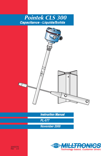
Milltronics Pointek CLS 300 电容胶带重量传感器说明书
A t Milltronics,we endeavourto design equipment that is simple to use and reliable in its operation,with the aim of satisfying our customers'needs.Milltronics has been designing and manufacturing electronics based process measurement equipment since1954.Our fields of expertise include continuous and point level measurement,weighing and feeding systems and motion sensing.Technologies include ultrasonic,capacitance and microwave radar.Milltronics sells and markets world wide through subsidiaries,distributors and representatives.Through continuous improvement,we are striving to provide our customers with first rate sales information,engineering assistance and after sales support.For more details on our products and services,please contact us and we will provide you with a listing of the offices or representatives nearest you.Table of ContentsAbout Pointek CLS 300 (5)Pointek CLS 300 Outputs (5)Pointek CLS 300 Features (5)Pointek CLS 300 Applications (5)Specifications (7)Installation (11)Location (11)Configuration and Dimensions (13)Standard Version (14)High Temperature Version (15)Ceramic Active Shield Insulator (16)Thermal Isolator (16)Rod Version (16)Changing the Probe’s Length (17)Cable (19)Cable Tensile Strength (20)Cable Weights (20)Shortening the Cable (20)Mounting (21)Multiple units (21)Wall Restriction (21)Process Concerns (22)Interconnection (23)Trip Amplifier (23)Relay Output Connection (24)Solid State Switch (24)Diode Protection (24)Ancillary 2-Wire Output Connection (25)Power Connection (3 or 4 wire connection) (25)Operation (27)Set Up (27)Start Up (28)Alarm Output (29)Troubleshooting (31)Maintenance (32)Appendix I: Application Notes (33)Application Notes (33)About Pointek CLS 300Note:Pointek CLS 300 is to be used only in the manner outlined in thisinstruction manual.The Pointek CLS 300 capacitance level switch provides output on high or low process material levels. When the measured material is at the desired level, the change in capacitance is sensed and a level alarm is triggered.This could be either a “high level alarm” (material rising to reach the desired level) or a “low level alarm” (material falling to reach desired level). Pointek CLS 300 OutputsOne form `C' (SPDT) relayOne isolated, non-polarized, solid-state switchPointek CLS 300 FeaturesNPT, BSPT, JIS (other connections on request)Corrosion resistant construction, PFA, Ceramic and 316L stainless steelwetted parts25m (82 ft) maximum insertion lengthRugged shear and abrasion resistant probeFully adjustable process alarm: level, time delayField adjustable insert lengthESD protection to 55 kv continuous dischargeActive shield technologyPointek CLS 300 ApplicationsLiquids, slurries, powders, granules, and solidsChemical and petrochemicalHigh pressure and temperaturePower Industry (fly-ash)SpecificationsProbeProcess Connections:•NPT/BSPT/JIS 1Wetted Parts:•Standard Version:•AISI 316L/PFA/Peek 2•High Temperature Version:•AISI 316L/Ceramics Al203 (99.7%)2Probe Lengths:•Rod Version:•min. 350mm (14”) - max. 1000mm (40”)•Rope/Cable Version:•min. 500mm (20”) - max. 25000mm (985”) Max. Tensile Force:•1900kg (4188lbs)Pressure Range3:•-1 to +35 barg (-14.6 to +511 psig)Temperature Range3:•Standard Version:•-40 to 200 °C (-40 to 392 °F)•High Temperature Version:•-40 to 400 °C (-40 to 752 °F)•Min. Dielectric Constant (>r):• 1.5Enclosure:•AluminiumEpoxy Coated:•yesNEMA/CSA/IP-Rating:•4/Type4/IP65Cable Inlet:•2 X ½"NPTCertifications:•CENELEC/FM/CSAPower Supply and TransmitterSupply Voltage:•12 - 250 Vac/dc any polarity galvanically isolatedPower consumption:•2VA/2WattWiring connections:•max. 2.5 mm2Temperature ranges:•Operation (Storage):•-40 to 85 °C (-40 to 185 °F)Signal indicators:•3, indicating adjustment control, output status and powerAdjustment Potentiometers:•2, one for time delay adjustment, one for sensitivity adjustmentAdjustment Switches:•5PST dip switch, for time delay select, fail safe selection, time delaytest/adjust, high/low sensitivity.Min. Sensitivity:•1% change in actual capacitanceMax. Temperature Drift:•0.2% of Actual Capacitance ValueMeasurement Frequency:•600 (kHz) maxESD protection•protected to 55kV continuous discharge.Output FunctionsRelay Contact•Contact:•Form ‘C’ (SPDT)(selectable NC or NO contact)•Max. Contact Load (dc):•5A/30Vdc•Max. Contact Load (ac):•8A/250Vac (cos n=1)•Max. Switching Capacity:•150Watt/2000VA•Min. Contact Load•10mA/5Vdc•Time Delay (on and/or Off)•1 - 60 sec.Solid State switch•Output:•Galvanically isolated•Safety:•Non-polarity sensitive transistor•Max. Load:•2 Watt•Max. Switch Voltage:•250Vac/300Vdc•Max. Load Current:•100 mA•Voltage Drop•Below 1 Volt typical @ 50mA•Time Delay (On and/or Off)•1 - 60 sec.Two (2) Wire Switch•With customer supplied external trip devicesProbe - StandardLength•350mm (14”) to 1000mm (40”)Process Size•NPT, ¾” , 1”,1¼”, 1½”•BSPT, ¾”, 1”, 1½”•JIS, ¾”, 1”, 1½”Insulating Material•Standard Version:•PFA•High Temperature Version:•Ceramic•No insulation on active probeTensile kg loadProbe - CableLength • 500mm (20”) to 25000mm (985”)Process Size • NPT/BSPT: 1¼” minimumInsulating Material• AISI 316L SS • PFA insulation optionalTensile kg load• 1900 kg (4188 lbs)Electrode Dimensions • Cable (insulated):•9mm (0.35”)(uninsulated):•6mm (0.24”)• Weight:•32 x 250mm (1.26 x 9.84”)• Butterfly:•175 x168mm (6.89 x 6.61”)Approvals• CE, CSA, NRTL/C, FM, CENELEC • refer to device nameplateInstallationLocationNotes:•Installation shall only be performed by qualified personnel and in accordance with local governing regulations.•This product is susceptible to electrostatic shock. Follow proper grounding procedures.The Pointek CLS 300 as supplied in the standard probe lengths is normally mounted on the vessel top (high detection alarm) or through the tank wall at the detection level (high or low detection alarm).The cable version is designed for top mounting. The cable suspendsvertically so that it reaches into the process at the desired detection level (high or low detection alarm).Angle HorizontalVerticalConfiguration and DimensionsStandard VersionHigh Temperature VersionCeramic Active Shield InsulatorThe High Temperature version, which includes a ceramic Active Shieldinsulator, is recommended when the process temperature is greater than200E C/ 392 E F and / or when the product to be detected is very abrasive. The high temperature version is rated for applications up to 400 E C / 752 E F. See Temperature and Pressure Recommendations for Application on page 33. Thermal IsolatorIf the ambient temperature of the transmitter is expected to exceed85E C/185E F, then a thermal isolator should be used. An isolator provides a separation distance between a high process temperature inside the vessel, and the electronic housing outside the vessel. This reduces the operatingtemperature of the electronics to a value equal or less than 85E C/185E F. Rod VersionThe rod version of the CLS 300 is available in standard lengths from 350Changing the Probe’s LengthThe probe’s length can be shortened in the field by cutting the electrode.Warning:To prevent damage, do not apply torque directly to the main probe assembly.Option 11.Remove the electrode byreleasing the set screw andturning the threadedelectrode end counterclockwise2.Place the upper part of theelectrode in a vice as shownin the Figure.e a wrench to loosen thelower portion of theelectrode.Option 2The Wrong WayIf the process connection itself is put in the vice, then the probe’s internalparts will rotate along with the wrench, and the unit may fail.Cable Tensile StrengthThe tensile strength of the cable at 1900 kg / 4188 lbs should not beexceeded. It is also important to confirm that the load carrying capability of the silo/tank roof is sufficient to withstand the actual force on the cable for any conditions where the force is likely to be as great as 1900 kg / 4188 lbs.A cable (rope) probe with a PFA jacket reduces the possible product build upon the probe, thus also the tensile force on the cable.Cable WeightsA standard weight with optional attachable butterfly enhancer is available forthe cable version. For lower dielectric constant materials (often in solids) the butterfly weight is recommended, since it increases the change incapacitance when the material comes in contact with the cable end. Thiswould be the case when the silo is quite tall (> 15 m/45 ft) and the dielectric< 4)constant is less than (>rShortening the CableThe cable can be shortened using either:•An angle grinder (preferably with a disc suitable for stainless steel); or •Wire cutters (suitable for piano cable Ø6 – 9 mm).To shorten the cable, proceed as follows:1.If present, remove Butterfly from weight;2.Loosen the three set screws and remove weight by pulling it from the cable;3.Grind/cut the cable to the required length, remove rough edges from thecable;4.Insure that the cable strands are properly seated in the lay of the cable (i.e.no wire strands sticking outside the normal cable profile). It is important to insure that this step is properly done before continuing the assembly.5.Push the weight onto the cable while at the same time rotating it counter-clockwise about the cable, making sure that no cable strands are pushed out of their position in the cable and that the cable is fully inserted;6.Re-fasten the weight by tightening the three set screws;7.Attach the butterfly to the weight again.MountingMultiple unitsSensors must be 500 mm (20”)apart.Mount diagonally if there is notenough vertical space.Process Concernskeep out of path of falling material consider material angle of repose protect probe from falling materialInterconnectionTrip AmplifierLoosen the lid clip and remove the enclosure cover.Identification label (underside of enc losure cover)Notes:• Switch and potentiometer settings are for illustration purposes only.Refer to Set Up on page 27.• Relay contact terminals are for use with equipment having noaccessible live parts and wiring having insulation suitable for at least 250 V ac.• Maximum working voltage between adjacent relay contacts shall be250 V ac8A –5A –Relay Output ConnectionRelay shown in de-energized state, K2contacts rated for 8A at 250 Vac / 5A at30 VdcSolid State SwitchSolid state switch to customer’scontrol or instrumentation deviceSwitch shown in de-energized state, K3contact rated for 250 Vac / 300 Vdc 100mA max 2 VA/2W max., non-polarized.Diode ProtectionWhen driving an external relay with either the solid stated switch and / or relay outputs using dc power, protection diodes must be connected in the correct polarity across the relay coil to prevent possible switch / relaydamage due to the inductive spikes generated by the relay coil.Switch capacity100mA max.2 VA/2W max,250 Vac/300 Vdc.Ancillary 2-Wire Output ConnectionNominal 24 Vdc48 Vdc DC volts 22-2646-50R (S)120234Power Connection (3 or 4 wire connection)12 –V dcRefer to Power ConnectionOperationSet UpNote:Set up can be done in the field with the Pointek CLS 300 mounted into process, or in the shop prior to mounting.Dip Switch 1Set on to change the alarm relay status immediately when the sensor detects a change in frequency. Use this setting when time is critical.Set off to change the alarm relay status with a delay by the amount set on potentiometer #1 (P1). Use this setting when you want to slow the response to account for turbulence or false readings.Dip Switch 2Set on to change the alarm relay status immediately when the sensor detects a change in frequency. Use this setting when time is critical.Set off to change the alarm relay status with a delay by the amount set on potentiometer #1 (P1). Use this setting when you want to slow the response to account for turbulence or false readings.Dip Switch 3Set off to indicate the Low fail safe selection.Set on to indicate the High fail safe selection.Dip Switch 4Set on to test the delay of the alarm relays as set by the potentiometer #1(P1).Set off for normal operation.Dip Switch 5Set on for normal sensitivity on the sensor. Use this setting in situations when you are measuring dry solids or non-conductive liquids.S1 - 1Delay offS1 - 2Fail-safeS1 - 3Delay testS1 – 4SensitivityS1 - 5 Disabled Disabled High Test NormalEnabled Enabled Low Normal low Start UpAfter the CLS is properly mounted and the switch bank set up, apply power to the unit. The green LED (L3) lights to indicate the unit is powered andoperational.IndicatorsThe Pointek CLS uses three LEDs for visual indication of the following:L1 (yellow), sensor status:when P2 is properly set, this LED is on whenthe sensor is in contact with the processmaterial (material capacitance is greaterthan the set point, P2). L1 is off when thesensor is out of contact with the processmaterial (material capacitance is less thanthe set point).L2 (red), output status:this LED is an indication of the relay andsolid switch contact status. Refer toOperation \ Output Status.L3 (green), power:this LED is on when the Pointek CLS isproperly powered.Proceed with the set up of the alarm output.delay ‘on’delay ‘off’fail safedelay testsensitivityAlarm OutputAlarm Output StatusCoveredUn-coveredSetpoint AdjustmentIn order to assist you in properly adjusting the alarm set point for reliable and accurate detection of the process material, we have categorized the materials and applications into two cases. Follow the setup procedure associated with the case which includes your application.Case 1:This is the general case encountered in most applications, characterized by the following:• dry solids• low viscosity liquids • hygroscopic / wet solids•high viscosity and high conductivity liquidsCase 2:Case 1Preamble:•insure that L3 (green) is `on '•turn both potentiometers, P1 and P2, fully ccw (counterclockwise)•set S1 switches 1 to 4 `off ' and S1 switch 5 to `on' (normal sensitivity)1.With sensor uncovered and a minimum 100 mm free space all around, turnP2 cw until L1 (yellow) goes `on '.2.Turn P2 ccw until L1 goes `off '.Case 2Preamble:•insure that L3 (green) is `on '•turn potentiometer P1 fully ccw (counterclockwise), and P2 fully cw (clockwise)•set S1 switches 1 to 5 `off '1.Immerse the sensor in the material that has the lowest dielectric constant.L1 (yellow) should be `on '. If not, S1 switch 5 should be set to `on' (normal sensitivity).2.Adjust P2 ccw until L1 goes `off '.3.Immerse the sensor in the material that has the highest dielectric constant,L1 should come `on '.DelayThe alarm actuation can be delayed for either or both `on alarm' and `off alarm' conditions. The selection is made by setting S1-1 and S1-2, refer to Set Up \ Switch Bank. The amount of delay is adjustable from 1 to 60seconds by setting potentiometer, P1.TroubleshootingNo alarm responseL3 off (green LED)Check power supply L1 (yellow) doesn ’trespond to reducing level on the electrodeCheck sensitivity, S1-5,electrode, connections to sensor input on trip amplifier (and zener barrier continuity if used)Alarm won ’t switch when material level moves down the electrodeL1 (yellow) responds to reducing level on the electrodeCheck that relay and L2(red LED) changes state when S1-3 is toggledL1 (yellow) doesn ’t respond to the sensing electrode approaching or touching.Check sensitivity S1-5,electrode, (and zener barrier continuity, if used)L1 (yellow) responds to increasing level on the electrodeAlarm doesn ’t switch when material level moves up the electrodeL1 (yellow) flashes when approaching the alarm trip-pointCheck that relay and L2(red LED) changes state when S1-3 is toggledMaintenanceThe Pointek CLS 300 requires no regular maintenance or cleaning. Even with significant build-up on the CLS 300 level detector electrode, the level switch will continue to operate. Build-up of material on the active shield area will have little or no effect on the performance of the CLS 300.Appendix I: Application Notes Application NotesTemperature and Pressure Recommendations for ApplicationAppendix II: CE ConformityWRITTEN DECLARATION OFCONFORMITYWe,Siemens Milltronics Process Instruments B.V.Nikkelstraat 10 - 4823 AB BREDA - The Netherlands Declare, solely under own responsibility, that the product Point Level Switch,Pointek CLS 300Mentioned in this declaration, complies with the following standards and/or normative documents:Requirements Remarks Certificate No.EMC Directive 89/336/EEC Commercial, lightIndustrial, and industrial97221-KRQ/EMC 00-4024 EN 55011: 1991Emission – Class BEN 50082-2: 1995 Generic Immunity Standard, from which:•EN 61000-4-2: 1995: Electrostatic Discharge (ESD) Immunity•EN 61000-4-3: 1996: Radiated Electro-Magnetic Field Immunity•ENV 50204: 1995: Digital Radio Telephones Immunity•EN 61000-4-4: 1995: Electrostatic Fast Transient (EFT) Immunity•EN 61000-4-5: 1995: Surge Transient Immunity•EN 61000-4-6: 1996: Conducted Radio-Frequency DisturbancesImmunityATEX Directive 94/9/EC Audit Report No. 2003068II 1/ 2 GD EEx d[ia] IIC T6…T10344T 100 °C IP 66KEMA 00ATEXQ3047KEMA 00ATEX2040XEN 50014: 1992General RequirementsEN 50018: 1994 Flameproof Enclosures “d”The notified body is:N.V. KEMA – Utrechtseweg 310 – 6812 AR Arnhem – The NetherlandsLocation: Breda Named Representative: C.S. van Gils Date: October 1, 2000Position: Managing DirectorNote: For specific safety specifications, please consult the instrument labelIndex2-Wire Connection (25)3 or 4 wire connection (25)About Pointek CLS 300 (5)Adjusting Probe Length (17)Alarm Output (29)Setpoint Adjustment (29)Status (29)Ancillary 2-Wire Output Connection (25)Angle of repose (22)Appendix (33)Appendix II (34)Application Notes (33)Applications (5)Approvals (9)Cable (19)Shortening it (20)Tensile Strength (20)Weights (20)Ceramic Active Shield Insulator (16)Certifications (7)Configuration (13)DECLARATION OF CONFORMITY..34 Dimensions (13)High Temperature Version (15)Standard Version (14)Diode Protection (24)Dip Switches (27)ElectrodeShortening the Probe (17)Enclosure coverremoving (23)Falling Material (22)Features (5)High Temperature Version (15)Dimensions (15)High TemperaturesRecommendations (16)Indicators (28)Installation (11)Location (11)Interconnection (23)Ancillary 2-Wire Output Connection25Diode Protection (24)Power Connection (25)LEDs (28)Location (11)Angle (11)Horizontal (11)Vertical (11)Maintenance (32)Material build up (22)Mounting (21)Multiple Units (21)Process Concerns (22)Wall Restriction (21)Operation (27)Alarm Output (29)Set Up (27)Start Up (28)Output status (28)Outputs (5)Pointek CLS 300 (5)Applications (5)Configuration (13)Dimensions (14)Features (5)Outputs (5)Power (28)Power Connection (25)3 or 4 wire connection (25)Power Supply (7)Protection diodes (24)Relay Output Connection (24)Rod Version (16)Sensor status (28)Set Up (27)Dip Switches (27)Setpoint Adjustment (29)Shield Insulator (16)Shortening Probe (17)Solid State Switch (24)Solid stated switch (24)Specifications (7)Standard Version (14)Dimensions (14)Start Up (28)Thermal Isolator (16)Transmitter (7)CANADAGERMANYSWITZERLANDSingapore,Brazil AUSTRALIABELGIUMFRANCEHONG KONGMEXICOTHE NETHERLANDSTHE UNITED KINGDOMTHE UNITED STATES1954 Technology Dr., P .O. Box 4225,Peterborough, Ontario, Canada K9J 7B1T el.: (705) 745-2431 Fax: (705) 741-0466August van de Wielelei 97, 2100 Deurne, Antwerp, BelgiumT el.: +32(0)3326 45 54 Fax: +32(0)3326 05 25Parc de la Sainte Victoire, Bât. 5, 13590, Meyreuil, FranceT el.: +33 4 42 65 69 00 Fax: +33 4 42 58 63 95T el.: (524) 248-1561 Fax: (524) 248-1565Nikkelstraat 10, NL-4823 AB Breda, The Netherlands Tel.: +31(0)76 542 7 542 Fax: +31(0)76 542 8 542709 Stadium Drive, Arlington, Texas U.S.A. 76011T el.: (817) 277-3543 Fax: (817) 277-3894A joint venture in a sales office in and distributors in56 countries.Visit our web site at:182 Normanby Rd., Box 339, South Melbourne, AustraliaT el.: +61 3-9695-2400 Fax: +61 3-9695-2450Friedrichstrasse 69, D-76703, Kraichtal, Germany T el: +49 721 595 4607 Fax: +49 721 595 49371 Hoi Wan Street, Suite 602, Quarry Bay, Hong Kong T el.: +85 2-2856-3166 Fax: +85 2-2856-2962Century House, Bridgwater Road, Worcester, England WR4 9ZQT el: +44 1905 450500 Fax: +44 1905 450501Printed in CanadaPaseo de Loma Dorada # 114, Loma Dorada, Querétaro, Qro. 76060CP 168, Crêt de Plan 23, CH-1095 LUTRYT el. +41 21 791 58 28 Fax. +41 21 791 58 40。
ASECL
3/20確認槽液中 氯含量的影響 將氯濃度 49PPM 提升至59PPM 後 確認光澤恢復, 但 量產約2小時後 再度失去光澤
3/19再度開線量產 發現電鍍除理後 版面無光澤 panel&pattern都一樣無光澤 初步判斷為光澤劑不足進行 1.300CCAJSTERE S添加 添加後光澤恢復約2小時後 再度版面失去光澤 2.濃度A劑:23.729,B劑2.6 3.進行哈士片測試,測試結果 哈士片表面有光澤,確認不是 CVS分析誤差 4.後續連續投入AJSTERE 300.500,200CC維持光澤進 行生產
後續連續投入ajstere300500200cc維持光澤進320確認槽液中氯含量的影響49ppm提升至59ppm密度高低的影響320將電流密度提升至25asd進行panel及pattern板電鍍確認25asd時pamel板面有光澤並與大野流密度25asd的panel板電鍍確認版面有光澤dummy10小時空氣攪拌322上午進行30片dummy後進行21asd電流密度進dummy增加至100片後25asd方可恢復光澤進行21asdpanel基板322晚上進行31asd電流密度118片量產板度下降後其不同的電流密度進行現場線測試主要以18
3/22 ASE 電流密度測試及表面狀態
電流密度;1.8asd 無光澤霧化 顯微鏡觀察 表面有平均白點發生
電流密度;2.1asd 無光澤霧化 顯微鏡觀察 銅面粗操,無完全結銅
電流密度;2.4asd 有光澤 顯微鏡觀察 銅面狀況細緻 且結銅完整
3/22 A劑;19cc/L,B劑;2.1cc/L 弱電解;0.2asd 4小時 空氣攪拌;10小時
總結 現ASE客戶要求需2液型管理的關係,將原本建議之TC-BRITE 211製程,轉換成 CU-BRITE 21製程. 21製程對余客戶產品及途中所發生的表面無光澤的問題.已得到滿足及解決 並總結於下列幾點 1.現針對課戶通孔基板,至今的實際測試可達到電流密度3.1ASD的高產量生產 (約之前羅門哈斯 901製程的3倍產量) 2.通孔的T/P達到100%(為原來901還增加20%) 3.可對應100/100盲孔板 (a.建議客戶將硫酸銅濃度從100g/L增加至120g/L(會犧牲通孔t/p約2~3%) b.將電流密度從2.2ASD降至1.5ASD c.將stb濃度降至1.2cc/L 對於孔底銅厚可達到客戶要求的20um) 4.現建議客戶現場控管濃度為A劑:10~30cc/L,B劑:1~2cc/L 5.自動添加部份現設定為1500AH A劑;100cc B劑;5cc
XD系列多晶X射线衍射仪技术说明书

XD系列多晶X射线衍射仪技术说明书北京普析通用仪器有限责任公司注意安全防护,当心射线伤害!X射线能对人体造成伤害,因此在使用X射线设备时必须十分注意安全,避免受到X射线的照射。
本机的设计虽然考虑到较周全的防护。
但若操作处置不当,仍然可能受到X射线照射。
此外,X射线发生器是一种高压设备,在检修时也必须十分注意安全,避免受到高电压的伤害。
1. 衍射仪X射光路的屏蔽部件不可随意移去。
2. 当需要推开防护罩门进行操作时,应十分注意不要受到X射线的照射。
注意不要受到X射线的直接照射,也要注意不要受到散射线的照射。
更换样品时必需关窗。
3. 当维修X射线发生器的高压部分时,必须切断电源并使高压电容完全放电。
前言 (6)第一章X射线发生器使用说明 (7)1. 概述 (7)1.1 用途与特点 (7)1.2 对使用环境的要求 (7)1.3 安装条件 (7)2. 主要技术指标 (8)2.1 直流高压发生器 (8)2.2 控制系统的X射线管工作高压、管工作电流调节与稳定电路 (8)2.3 保护电路 (8)2.4 高压电缆 (9)3. X射线管 (9)4. 控制系统的结构及工作原理 (9)4.1 结构特征 (9)4.2 工作原理 (10)5. 使用方法及操作说明 (14)5.1 安装前的准备工作 (14)5.2 安装 (16)5.3 操作顺序及简单调校 (16)5.4 X射线窗口开闭 (17)5.5 使用注意事项 (17)5.6 日常例行检查项目 (17)6. 故障排除与维修 (18)6.1 开机步骤和可能出现的故障 (18)6.2 故障的排除 (20)6.3 附图 (22)第二章单道脉冲幅度分析器 (36)1. 引言 (36)2. 使用环境 (36)3. 工作原理及其技术指标的性能 (36)3.1 直流低压电源: (36)3.2 高压电源 (37)3.3 放大–单道分析器 (37)3.4 定标计数单元 (38)4. 操作说明 (39)第三章直流高压发生器 (40)1. 安全 (40)1.1 和配套装置的联用 (40)1.2 发生器的空载试验 (40)1.3 发生器的检修 (40)2. 发生器的技术规格 (41)2.1 负载工作参数 (41)2.2 工作制式 (41)2.3 测量点特性 (41)3. 产品的维护 (41)3.1 高压插座和高压电缆的插头的维护 (41)3.2 检查辉光放电管 (42)3.3 检查注油孔上的密封塑料管套 (42)3.4 检查冷却水管的接头 (42)4. 发生器线路原理图 (43)第四章测角仪 (44)1. 概述 (44)2. 组成 (44)3. 主要技术特性 (44)4. 结构描述 (45)5. 安装 (45)6. 测角仪的校直(对零) (46)6.1 测角仪校正的具体要求 (46)6.2 测角仪校正的具体步骤 (47)6.3 测角仪的衍射角测量准确度和衍射角分辨率的检查 (47)7. 测角仪的维护保养及使用注意事项 (49)第五章操作与分析软件 (50)1. 概述 (50)2. PDP衍射分析系统的运行环境与硬件配置 (50)3. 软件安装 (50)4.版权信息 (50)5. 正确安装后的文件目录结构 (51)6. 关于系统参数设置文件PDP.INI (51)7. PDP程序的使用 (51)7.1 寻峰 (52)7.2 “求峰面积、峰高、重心、积分宽度”和“背景扣除” (56)7.3 减背景 (57)7.4 图谱对比 (57)7.5 关于Pdp应用软件所使用与支持的文件格式 (58)第六章石墨弯晶单色器 (59)1. 概述 (59)2. 技术数据 (60)3. 结构 (60)4. 调整 (61)5. 使用的工作条件选择 (61)6. 注意事项 (61)第七章XD-2/3多晶X射线衍射仪操作规程 (62)1. 衍射仪(XD-2/3)对环境的要求 (62)2. 开机过程 (62)3. 关机顺序 (63)前言首先,感谢您购买北京普析通用仪器有限责任公司的产品!为了您更好的使用本仪器,请在使用前详细阅读本说明书,按照操作规程使用仪器。
DL 系 列 袋 式 过 滤机中英文说明书
五、 主要规格和技术参数(仅供参考) Main Specifications and Technical Parameters
型号 Model
过滤面积 Filtration
area (m²)
进出 口径 Caliber of the inlet/outlet
最高流量 M³/h
筒体直径
<粘度=1 厘泊>
Email : xsb@ Tel:+86-510-87501891、86-510-875088993
Website:
Fax: +86-510-87501218
一、 产品简介 Brief Introduction to the Products
DL 系 列 袋 式 过 滤 机 Serial DL Bag-type Filters
使 用 说 明 书 User's Manual
江苏巨能机械有限公司 JIANGSU JUNENG MACHINERY CO;LTD
Address : Chaoyang Rd , Zhoutie Town, Yixing City, Jiangsu Province , P.R.China
锁紧圈,用专用锁紧工装锁紧滤袋及“O”形圈,然后合上上封头盖,旋紧锁紧手轮,即可 投入工作。Multi-core bag-type filter: Open the upper end plate cover, place the filer bag with the required degree of fineness into every reinforced filter gauze, place the locking ring, lock the filter bags and O-ring with special locking tools, cover the upper end plate cover and screw the locking hand-wheel tight. Then the filer can be brought into use. 2. 泵启动后,过滤机上压力微微上升,初时压力约 0.05MPa 左右,随着使用时间的延长,缸内 滤渣逐渐增多,当压力达到 0.4MPa 时,应停机打开缸盖,检查滤袋积渣情况,可更换滤袋继 续使用(滤袋经过清洗一般可重复使用)。After the pump has been started up, the pressure of the filter begins to ascend lightly and the initial pressure of the filter is about 0.05MPa. Along with the extension of time, the filter residue in the jar increases gradually. When the pressure reaches 0.4MPa, the filter should be stopped to open the cover of the jar to check the residue accumulation in the filer bag. The filter can be continually used after the filter bag has been replaced(the replaced filter bag can be repeatedly used after being cleaned). 3.过滤缸压力一般可调在 0.1~0.3MPa 比较合适,这可调节泵上回流阀来达到,滤缸压力过高会 损坏滤袋以及加强网,须格外注意。 Generally, it is very moderate for the pressure of the filtering jar to be regulated between 0.1 and 0.3MPa, which can be realized through the regulation of the return valve on the pump. If the pressure is too high, it might be possible for the filter bag and reinforced gauze to be damaged. Therefore, you’d better to be especially cautious.
CCL介绍
基材主要指的是介电 材料,其组成为树脂、 增强材及填充剂。
本文将对目前应用于 电子工业的基材进行 介绍,并对其制作工 艺特点及可靠性要求 作简单描述。
最后对基材的发展趋势进行粗略描述,提供参考。
二、覆铜板用基础材料--铜箔
A、铜箔——Copper Foil ——Copper
铜箔的作用是用于形成表面线路,进行导通。铜箔按生产工艺主 要分两类: A1、电解铜箔 ED Foil-Electrodeposited Foil
7628 2116 1080 106
二、覆铜板用基础材料--填充剂 覆铜板用基础材料--填充剂
填充剂的种类——Fillers ——Fillers
在覆铜板(CCL ) 中应用填料(Fillers)按种类主要分为: A 硅微粉(二氧化硅) B 氢氧化铝 C 滑石粉 E 云母粉、高岭土、等用量较少的填料
压力与时间的配合压制程式截图压制程式截图压制用冷热一体压机压制用冷热一体压机热分解稳定decompositiontemperature介电常数与介电损耗角正切permittivitydklosstangentdf抗弯强度flexuralstrength剥离强度peelstrength吸水率moistureabsorption浸焊thermalstress1010阻燃测试flammability性能测试遵循性能测试遵循ipc1401cipc1401c版版五性能测试玻璃化转变温度玻璃化转变温度tgtg玻璃化转变是非晶态高分子材料固有的性质是高分子运动形式转变的宏观体现它直接影响到材料的使用性能和工艺性能因此长期以来它都是高分子物理研究的主要内覆铜板材料的tg关系到板材在高温下的形变量弯曲强度等指标
热层
氧 层
层
Shiny Side SEM
施耐德LC1D系列接触器(选型表)

245A
LC1D245F7C
LC1D245M7C
LC1D245Q7C
300A
LC1D300F7C
LC1D300M7C
LC1D300Q7C
410A
LC1D410M7C
475A
LC1D475M7C
620A
LC1D620F7C
LC1D620M7C
LC1D620Q7C
电流
AC48V
DC24V
施耐德LC1D系列接触器(选型表
电流
线圈电压(AC/DC选型)
AC24V
AC36V
AC110V
AC220V
AC380V
9A
LC1D09B7C
LC1D09CC7C
LC1D09F7C
LC1D09M7C
LC1D09Q7C
12A
LC1D12B7C
LC1D12CC7C
LC1D12F7C
LC1D12M7C
LC1D12Q7C
LC1D65CC7C
LC1D65F7C
LC1D65M7C
LC1D65Q7C
80A
LC1D80B7C
LC1D80CC7C
LC1D80F7C
LC1D80M7C
LC1D80Q7C
95A
LC1D95B7C
LC1D75CC7C
LC1D95F7C
LC1D95M7C
LC1D95Q7C
115A
LC1D11500B7C
LC1D11500F7C
LC1D11500M7C
LC1D11500Q7C
150A
LC1D15000B7C
LC1D15000F7C
LC1D15000M7C
TCL300DL1-A中文资料

ACCESSORIESLMSHELF = Mounting Shelf 300-450W MXSHELF = Mounting Shelf 72-200W C1063R49/02 IHOrdering InformationSERIES DC WATTAGE HEADS HEADS OPTIONS 1CCL = 6 Volt 6 Volt6 Volt3 = Three A = Ammeter 2TCL = 12 Volt75 = 75 Watts DY = 8 Watt, Tungsten 2 = Two ACF1 = 120 VAC Fuse 100 = 100 Watts DA = 18 Watt, Tungsten 1 = OneACF2 = 277 VAC Fuse 150 = 150 Watts DL = 25 Watt, Tungsten ACP1 = 120 VAC Power Switch 225 = 225 WattsDC = 30 Watt, Tungsten ACP2 = 277 VAC Power Switch AD = ACCU-TEST Self-Diagnostics 12 Volt (Includes standard voltmeter)12 VoltADAL = ACCU-TEST with Alarm150 = 150 Watt DNY = 12 Watt, Tungsten ADTD = ACCU-TEST with Time Delay 3200 = 200 Watt DE = 28 Watt, Tungsten DCP = DC Power Switch300 = 300 Watt DK = 25 Watt, Tungsten EX = Special Input Transformer (Specify voltage and frequency)450 = 450 WattDG = 30 Watt, TungstenTD1 = 120 VAC Time Delay 3TTD2 = 277 VAC Time Delay 3(Suggested lamp heads listedV = Voltmeter 2above. Refer to the Accessories Section for W = White Housingadditional lamp head choices.)CCL15016.0”(40.6 cm)TCL300, TCL4506.0”(15.2 cm)7.6”(19.3 cm)12.0”(30.5 cm)27.0”(12.7 cm)6.0”(15.2 cm)7.6”(19.3 cm)12.0”(30.5 cm)Notes:1) Some option combinations may impact UL list-ing. consult factory for specifics.2) Not available witj AD, ADAL, or ADTD options.3) 15 minute delay.元器件交易网Housing18 gauge steel housing with a tan epoxy powder coat finish.Knockouts provided for mounting up to three lamp heads.The suggested lamp head is the “D” Series round sealed beam Par 36 tungsten. To order lamp heads other than the suggested “D” head, refer to Chloride Accessories Section..Suggested SpecificationFurnish and install Chloride Systems emergency lighting unit model ________. The unit shall be constructed to meet Underwriter’s Laboratories, Inc. Standard #924and the National Electrical Code (NEC).INSTALLATION AND OPERATION -Unit shall be easily field connected to a 120 or 277 VAC, 60 hertz, unswitched power source. Installation must comply with the NEC as well as other applicable codes. Upon utility power failure or brownout, the unit shall automatically transfer to battery power and maintain the required illumina-tion level for a minimum period of 90 minutes. Upon restoration of utility power, the charger shall restore the battery to full charge within UL 924 requirements follow-ing a rated discharge of not more than 90 minutes.CHARGER -Product shall utilize a fully automatic, voltage regulated, two-rate current limited solid-state charger. The charging system shall maintain the battery at full capacity without the need for periodic exercising or equalization. The following features shall be standard: Low voltage disconnect (LVD), brownout protection and AC lockout.BATTERY -The battery shall be a low maintenance, free electrolyte, wet cell, lead calcium battery. The lead calcium battery shall provide trouble-free operation in temperatures up to 85°F (30°C).HOUSING -The unit housing shall be constructed of 18 gauge steel with a tan epoxy powder coat finish.Chloride SystemsISO 9001A2528C1063R49/02 IH272 West Stag Park Service Road •Burgaw NC 28425Telephone: (910) 259 1000 •Facsimile: (800) 258 Lamp Head Photometrics(For DL, suggested head for CCL)(For DK, suggested head for TCL)Vertical203050100Up 2010feet 010Down 20.2.1406070.31.5Horizontal203050100Left 2010feet 010Right 20.2.1406070.31.5203050100Up 2010feet 010Down 20Photometric No. 3406070801.3.2.1.5Horizontal203050100Left 3010feet 01020Right 301.3.2.120.540607080。
高亮度三色PLCC6黑体LED数据手册说明书

ASMT-YTC2-0AA02High Brightness Tricolor PLCC6 Black Body LEDData SheetDescriptionThe high brightness black top surface tri-color PLCC-6 family of SMT LEDs has a separate heat path for each LED dice, enabling the LED to be driven at higher current. These SMT LEDs are in the high brightness category, are high reliability devices, are high performance and are designed for a wide range of environmental condi-tions. By integrating the black top surface Avago devices deliver better contrast enhancement for your applica-tion. They also provide super wide viewing angle at 120° with the built in reflector pushing up the intensity of the light output. The high reliability characteristics and other features make the black top surface tri-color PLCC-6 family ideally suitable for exterior and interior full color signs ap-plication conditions.For easy pick & place, the LEDs are shipped in EIA-com-pliant tape and reel. Every reel is shipped from a single intensity and color bin; except red color providing betteruniformity. These tri-color LEDs are compatible with reflow soldering process.Featuresx Industry Standard PLCC-6 package (Plastic Leaded Chip Carrier) with individual addressable pin-out for higher flexibility of driving configuration x High reliability LED package with silicone encapsulation x High brightness using AlInGaP and InGaN dice technologies x Wide viewing angle at 120qx Compatible with reflow soldering process x JEDEC MSL 2ax Water-Resistance (IPX6*) per IEC 60529:2001* The test is conducted on component level by mounting the components on PCB with proper potting to protect the leads. It is strongly recommended that customers perform necessary tests on the components for their final application.Applications x Indoor full color display CAUTION: LEDs are Class 1C ESD sensitive. Please observe appropriate precautions during han-dling and processing. Please refer to Avago Application Note AN-1142 for additional details.Table 1. Device Selection GuidePart NumberColor 1 - AlInGaP Red Color 2 - InGaN Green Color 3 - InGaN Blue Min. Iv @20mATyp. Iv @ 20mA Max Iv @ 20mA Min. Iv @ 20mA Typ. Iv @ 20mA Max Iv @ 20mA Min. Iv @ 20mA Typ. Iv @ 20mA Max Iv @ 20mA Bin ID (mcd)(mcd)(mcd)Bin ID (mcd)(mcd)(mcd)Bin ID (mcd)(mcd)(mcd)ASMT-YTC2-0AA02T2355450715U1450560900R2140180285Notes:1. The luminous intensity I V , is measured at the mechanical axis of the LED package and it is tested in pulsing condition. The actual peak of the spatial radiation pattern may not be aligned with this axis.2. Tolerance = ± 12%Part Numbering SystemPackaging Option Color Bin Selection Intensity Bin Limit Intensity Bin SelectionDevice Specification Configuration Package Type C: Black Body Tricolor ColorT: TricolorProduce FamilyY: Silicone Based PLCC6Notes:1. All Dimensions are in millimeters2. Tolerance = ±0.2 mm unless otherwise specified3. Terminal Finish: Ag plating4. Encapsulantion material: silicone resin (Full Black Body)Lead Configuration1Cathode Blue 2Cathode Green 3Cathode Red 4Anode Red 5Anode Green 6AnodeBluePackage Dimensions10.534256Table 2. Absolute Maximum Ratings (T A = 25°C)Parameter Red Green & Blue Unit DC forward current [1] 5030mA Peak forward current [2]100100mA Power dissipation125114mW Reverse voltage4V[3]V Maximum junction temperature T j max125°C Operating temperature range -40 to + 110[4]°C Storage temperature range-40 to + 120°C Notes:1. Derate linearly as shown in Figure 4a & 4b.2. Duty Factor = 10% Frequency = 1KHz3. Driving the LED in reverse bias condition is suitable for short term only4. Refer to Figure 4a and figure 4b for more informationTable 3. Optical Characteristics (T A = 25°C)ColorDominant Wavelength,O d (nm) [1]Peak Wavelength,O p (nm)Viewing Angle2T½[2] (Degrees)Luminous EfficacyK V[3] (lm/W)Luminous EfficiencyK e (lm/W) Min Typ.Max Typ.Typ.Typ.Typ.Red61862262862912021022Green525530 53752112053525Blue465470477464120845Notes:1. The dominant wavelength is derived from the CIE Chromaticity Diagram and represents the perceived color of the device.2. T½ is the off axis angle where the luminous intensity is ½ the peak intensity3. Radiant intensity, Ie in watts / steradian, may be calculated from the equation Ie = I V / K V, where I V is the luminous intensity in candelas and K V isthe luminous efficacy in lumens / watt.4. )V is the total luminous flux output as measured with an integrating sphere at mono pulse condition.Table 4. Electrical Characteristics (T A = 25°C)ColorForward Voltage,V F (V) [1]Reverse VoltageV R @ 100P AReverse VoltageV R @ 10P AThermal ResistanceR T J-P (°C/W) [2] Min Typ.Max.Min.Min.TypRed 1.80 2.10 2.504–280 Green2.80 3.20 3.80–4180 Blue 2.80 3.20 3.80–4180 Notes:1. Tolerance ± 0.1V.2. One chip on thermal resistanceFigure 1. Relative Intensity vs Wavelength Figure 2. Forward Current-mA vs Forward Voltage-VFigure 3. Relative Intensity vs Forward CurrentFigure 4a. Maximum forward current vs. ambient temperature. Derated based on T JMAX = 125°C. (3 chips)Figure 4b. Maximum forward current vs. ambient temperature. Derated based on T JMAX = 125°C. (single chip)0.00.20.40.60.81.0WAVELENGTH - nmR E L A T I V E I N T E N S I T Y 020406080100FORWARD VOLTAGE-VF O R W A R D C U R R E N T -m A0.00.51.01.52.02.53.03.54.04.55.0DC FORWARD CURRENT-mAR E L A T I V E L U M I N O U S I N T E N S I T Y (N O R M A L I Z E D A T 20m A )010203040506020406080100120AMBIENT TEMPERATURE (°C)M A X A L L O W A B L E C U R R E N T -m A AlInGaPInGaN 0102030405060020406080100120AMBIENT TEMPERATURE (°C)M A X A L L O W A B L E C U R R E N T - m AAlInGaPInGaNFigure 5a. Radiation Pattern for X axisFigure 5b. Radiation Pattern for Y axisFigure 5c. Component Axis for Radiation PatternsFigure 6. Relative Intensity vs Junction Temperature Figure 7. Forward Voltage vs Junction TemperatureXX YYN O R M A L I Z E D L O P a t T J =25°C0.1110----0.0.F O R W A R D V O L T A G E S H I F T - VT J - J UNC TI ON TE MP E RA T UR E &T J - J UNC TI ON TE MP E RA T UR E &0.00.20.40.60.81.0-90-60-300306090ANGU L AR D I SP L AC E M E N T - D E GR EEN O R M A L I Z E D I N T E N S I T Y00.20.40.60.81ANGU L AR D I SP L AC E M E N T - D E GR EEN O R M A L I Z E D I N T E N S I T YFigure 8b. LED Configuration on land patternFigure 9. Recommended Pick and Place Nozzle TipTI METI MET E M P E R A T U R EFigure 10. Recommended leaded reflow soldering profile.Figure 11. Recommended Pb-free reflow soldering profile.Note: For detail information on reflow soldering of Avago surface mount LEDs, do refer to Avago Application Note AN 1060 Surface Mounting SMTLED Indicator ComponentsFigure 8a. Recommended soldering land pattern.I DI D = 1.7mm OD = 3.5mme fl o w l der ing i re cti o nFigure 12. Carrier tape DimensionFigure 13. Reel DimensionWITH DEPRESSION (0.25 mm)4.00P a ck a g e 10+–0.11101Figure 14. Reeling OrientationIntensity Bin LimitBin IDMin (mcd)Max (mcd)R2140.0180.0S1180.0224.0S2224.0285.0T1285.0355.0T2355.0450.0U1450.0560.0U2560.0715.0V1715.0900.0Tolerance for each bin limits is ±12%Color Bin Selection (X 2, X 3)Individual reel will contain parts from 1 half bin onlyX 2Min Iv Bin (Minimum Intensity Bin)RedGreenBlueAT2U1R2X 3Number of Half Bin from X 2RedGreenBlueA333Color Bin Selection (X 4)Individual reel will contain parts from 1 full bin onlyX 4Color Bin CombinationsRedGreenBlueFulldistributionA,B,CA,B,C,D,EPackaging Option (X 5)OptionTest CurrentReel Size220mA7 inchColor Bin Limits Red Color Bin TableBin IDMin DomMax DomFullDistribution618628x 0.68730.66960.68660.7052y0.31260.31360.29670.2948Tolerance of each bin limit is ± 1 nmGreen Color Bin TableBin IDMin DomMax DomA 525.0531.0x 0.11420.17990.21380.1625y 0.82620.67830.66090.8012B 528.0534.0x 0.13870.19710.22980.1854y 0.81480.67030.65070.7867C531.0537.0x 0.16250.21380.24540.2077y0.80120.66090.63970.7711Tolerance of each bin limit is ± 1 nmBlue Color Bin TableBin IDMin DomMax DomCorner Point1234A 465.0469.0x 0.13550.17510.1680.127y 0.03990.09860.10940.053B 467.0471.0x 0.13140.17180.16380.122y 0.04590.10340.11670.063C 469.0473.0x 0.12670.1680.15930.116y 0.05340.10940.12550.074D 471.0475.0x 0.12150.16380.15430.1096y 0.06260.11670.13610.0868E473.0477.0x 0.11580.15930.14890.1028y0.07360.12550.14900.1029Tolerance of each bin limit is ± 1 nmFor product information and a complete list of distributors, please go to our web site: Avago, Avago Technologies, and the A logo are trademarks of Avago Technologies in the United States and other countries.Data subject to change. Copyright © 2005-2010 Avago Technologies. All rights reserved. AV02-2589EN - October 5, 2010DISCLAIMER: Avago’s pro ducts and so ftware are no t specifically designed, manufactured o r autho rized fo r sale as parts, co mpo nents o r assemblies fo r the planning, co nstructio n, maintenenace o r direct o peratio n o f a nuclear facility or for use in medical devices or applications. Customer is solely responsible, and waives all rights to make claims against avago or its suppliers, for all loss, damage, expense or liability in connection with such use.Handling PrecautionThe encapsulation material of the LED is made of silicone for better product reliability. Since silicone is a soft material, avoid pressing on the silicon or poking the silicon with a sharp object as the product could be damaged and cause premature failure. During assembly handling, the unit should be held by the body only. Please refer to Avago Application Note AN 5288 for additional handling infor-mation and proper procedures.Moisture SensitivityThis product has a Moisture Sensitive Level 2a rating perJEDEC J-STD-020. Refer to Avago Application Note AN5305, Handling o f Mo isture Sensitive Surface Mo unt Devices, for additional details and a review of proper handling procedures.A. Storage before use– An Unopened moisture barrier bag (MBB) can be storedat <40°C/90%RH for 12 months. If the actual shelf life has exceeded 12 months and the humidity Indicator Card (HIC) indicates that baking is not required, then it is safe to reflow the LEDs per the original MSL rating.– It is recommended that the MBB not be opened prior to assembly (e.g. for IQC).B. Control after opening the MBB– The humidity indicator card (HIC) shall be read immedi-ately upon opening of MBB.– The LEDs must be kept at <30°C/60%RH at all times and all high temperature related processes including soldering, curing or rework need to be completed within 672 hours.C. Control for unfinished reel– Unused LEDs must be stored in a sealed MBB with desiccant or desiccator at <5%RH.D. Control of assembled boards – If the PCB soldered with the LEDs is to be subjected to other high temperature processes, the PCB need to be stored in sealed MBB with desiccant or desiccator at<5%RH to ensure that all LEDs have not exceeded theirfloor life of 672 hours.E. Baking is required if:– The HIC indicator is not BROWN at 10% and is AZURE at 5%.– The LEDs are exposed to condition of >30°C/60% RH atany time.– The Led floor life exceeded 672hrs.The recommended baking condition is: 60±5°C for 20hrs。
维萨拉Indigo系列产品说明书
感知成功维萨拉Indigo系列DRYCAP®探头露点CARBOCAP®探头二氧化碳PEROXCAP®探头过氧化氢HUMICAP®探头油中水Insight PC 机软件气压计压力模块(可选项)Indigo300Indigo200Indigo500系列Indigo80液体浓度Polaris ™折光仪温度湿度Ref. B212707EN-A ©Vaisala 2023目 录通过维萨拉Indigo系列感知成功 (4)Indigo520数据处理单元 (9)Indigo510数据处理单元 (12)Indigo200系列数据处理单元 (15)Indigo300数据处理单元 (17)Indigo80手持式显示表头 (20)用于测量相对湿度的维萨拉HUMICAP® 传感器 (23)HMP1墙面式温湿度探头 (25)HMP3一般用途湿度和温度探头 (27)HMP4相对湿度和温度探头 (30)HMP5相对湿度和温度探头 (33)HMP7相对湿度和温度探头 (36)HMP8相对湿度和温度探头 (39)HMP9紧凑型湿度和温度探头 (42)TMP1温度探头 (45)HMP80系列手持式湿度和温度探头 (47)Vaisala DRYCAP® 传感器用于测量干燥过程中的湿度 (49)DMP5露点和温度探头 (51)DMP6露点探头 (54)DMP7露点和温度探头 (56)DMP8露点和温度探头 (58)DMP80系列手持式露点和温度探头 (61)适用于苛刻环境的维萨拉CARBOCAP® 测量传感器 (64)GMP251二氧化碳探头 (66)GMP252二氧化碳探头 (69)用于测量油中微水的维萨拉HUMICAP® 传感器 (72)MMP8油中水分探头 (74)用于测量汽化过氧化氢、相对饱和度和相对湿度的维萨拉PEROXCAP® 传感器 (76)用于过氧化氢、湿度和温度测量的HPP270系列探头 (79)34广泛的测量参数范围•湿度和温度•露点•油中水分•二氧化碳 (CO 2)•气化过氧化氢 (H 2O 2)图册通过一种新方法步入未来,以测量您关键的工业性工艺流程。
CCL知识简介
一、专业知识简介覆铜箔积层板(Copper Clad Laminate),简称覆铜板或基板,英文简称CCL,是电子行业的基础材料,是由介电层(树脂Resin ,玻璃纤维Glass fiber ),及高纯度的导体(铜箔Copper foil )二者所构成的复合材料(Composite material),可在其上形成导电图形。
CCL是PCB制造不可缺少的原材料之一,根据NEMA标准可划分为G10、G11、FR-4、FR-5四种环氧玻璃纤维布基覆铜板。
我们公司生产的主要为FR-4基板.CCL的分类a、按覆铜板的机械刚性分为刚性覆铜板和扰性覆铜板;b、按覆铜板的绝缘材料、结构分为有机树脂类覆铜板、金属基覆铜板、陶瓷基覆铜板;c、按覆铜板的厚度分为厚板(板厚范围在0.8~3.2mm(含Cu))、薄板(板厚范围小于0.78mm(不含Cu));d、按覆铜板的增强材料划分为玻璃布基覆铜板、纸基覆铜板、复合基覆铜板(CME-1、CME-2)。
e、按照阻燃等级划分为阻燃板与非阻燃板。
f、按覆铜板的某些性能划分为高Tg板(Tg≥170℃)、高介电性能板、高CTI板(CTI≥600V)、环保型覆铜板(无卤、无锑)、紫外光遮蔽型覆铜板。
FR两个英文字母代表Flame Retardant,表示具有阻燃性。
FR-4的定义出自NEMA规范L11-1983,是指玻纤环氧树脂的烧样本,其尺寸为5″×0.5″厚度不限的无铜箔基板(光板)。
以特定本生灯在样本斜放45°的试烧下将其点燃,随即移开火源而让加有阻燃剂的板材自行熄灭,并以秒表记录离火后“延烧”的时间。
经过十次试烧后其总延烧的时间低于50sec称为V-0,低于250sec称为V-1,凡符合V-1的玻纤环氧树脂板材即称为FR-4。
铜箔:铜箔是生产CCL和PCB的不可缺少的原材料。
按照制法的不同,可分为压延铜箔和电解铜箔两种压制覆铜板一般使用电解铜箔第 1 页共14 页电解铜箔是通过专用电解机利用电解原理连续生产初产品(称为毛箔),再对毛箔进行耐热层钝化处理加工而成。
procline300分子量

procline300分子量
(最新版)
目录
1.Procline300 简介
2.Procline300 分子量的计算
3.Procline300 的应用领域
正文
1.Procline300 简介
Procline300 是一种合成蛋白质,由多个氨基酸组成。
在生物科技和制药领域,Procline300 被广泛研究和应用,因为它具有独特的生物活性和生物相容性。
了解 Procline300 的分子量对于研究和应用具有重要意义。
2.Procline300 分子量的计算
Procline300 的分子量可以通过计算其组成氨基酸的分子量之和得到。
氨基酸是蛋白质的基本组成单位,每个氨基酸的分子量不同。
Procline300 由 300 个氨基酸组成,因此其分子量可以通过将每个氨基酸的分子量相加得到。
3.Procline300 的应用领域
由于 Procline300 具有独特的生物活性和生物相容性,它被广泛应用于生物科技和制药领域。
在药物输送、组织工程、生物成像等方面,Procline300 发挥着重要作用。
此外,Procline300 还在生物材料、生物能源等领域有一定的应用前景。
总之,Procline300 作为一种具有重要生物活性和生物相容性的合成蛋白质,了解其分子量对于研究和应用具有重要意义。
第1页共1页。
国内外氯化聚丙烯产品简介
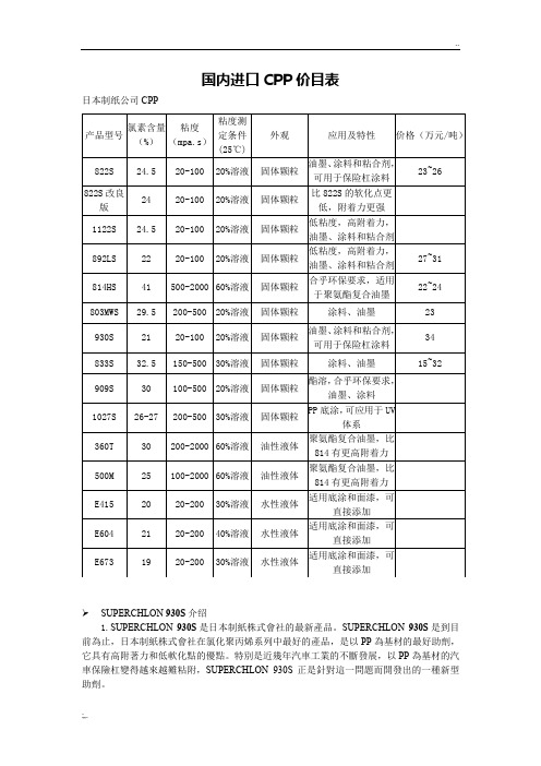
国内进口CPP 价目表日本制纸公司CPPSUPERCHLON 930S 介绍1.SUPERCHLON 930S 是日本制紙株式會社的最新產品。
SUPERCHLON 930S 是到目前為止,日本制紙株式會社在氯化聚丙烯系列中最好的產品,是以PP 為基材的最好助劑,它具有高附著力和低軟化點的優點。
特別是近幾年汽車工業的不斷發展,以PP 為基材的汽車保險杠變得越來越難粘附,SUPERCHLON 930S 正是針對這一問題而開發出的一種新型助劑。
产品型号 氯素含量(%) 粘度(mpa.s )粘度测定条件(25℃) 外观 应用及特性 价格(万元/吨)822S 24.5 20-100 20%溶液 固体颗粒 油墨、涂料和粘合剂,可用于保险杠涂料 23~26 822S 改良版 24 20-100 20%溶液 固体颗粒 比822S 的软化点更低,附着力更强 1122S 24.5 20-100 20%溶液 固体颗粒 低粘度,高附着力,油墨、涂料和粘合剂 892LS 22 20-100 20%溶液 固体颗粒 低粘度,高附着力,油墨、涂料和粘合剂 27~31 814HS 41 500-2000 60%溶液 固体颗粒 合乎环保要求,适用于聚氨酯复合油墨22~24 803MWS 29.5 200-500 20%溶液 固体颗粒 涂料、油墨 23 930S 21 20-100 20%溶液 固体颗粒 油墨、涂料和粘合剂,可用于保险杠涂料34 833S 32.5 150-500 30%溶液 固体颗粒 涂料、油墨 15~32 909S 30 100-500 20%溶液 固体颗粒 酯溶,合乎环保要求,油墨、涂料 1027S 26-27 200-500 30%溶液 固体颗粒 PP 底涂,可应用于UV体系 360T 30 200-2000 60%溶液 油性液体 聚氨酯复合油墨,比814有更高附着力 500M 25 100-2000 60%溶液 油性液体 聚氨酯复合油墨,比814有更高附着力 E415 20 20-200 30%溶液 水性液体 适用底涂和面漆,可直接添加 E604 21 20-200 40%溶液 水性液体 适用底涂和面漆,可直接添加 E6731920-200 30%溶液 水性液体适用底涂和面漆,可直接添加2.一般性質外觀:淺黃色至淺棕色的顆粒固體氣味:少許樹脂氣味遊離氯:無溶劑:能溶於環已烷、甲基環已烷、甲苯、二甲苯、脂環烴類(正已烷等)。
塑料原材料牌号及用途明细表

吉林石化
2
含爽滑剂,用于农膜、重包装膜、复合膜及管材、电线、电缆
9020
天津联合
2
用于农用微膜、多层共挤复合膜、10微米以下的各种薄膜及各种果蔬的保湿袋
1802
扬子石化
2
加开口剂,用于农膜、包装膜等
7050
中原乙烯
薄膜级,适用于各种农膜、地膜、日用包装袋、垃圾袋及各种注塑件、薄膜制品、农用小口径排水管材等
用作薄膜,吹膜、大棚膜、地膜、包裹袋及建筑工人保护带
7080
福建炼化
用于生产大棚膜、内衬、中等厚度膜等
LLDPE-缠绕膜类
9030
天津联合
2
用于拉伸缠绕膜及各种拉伸薄膜
QLLF-020AA
上海赛科
流延膜(缠绕膜、多层膜、掺混)
LLDPE-茂金属类
18H27DX
大庆石化
流动性好,用于高韧度复合膜、外包裹膜.、缠绕膜、重包装袋(吹膜)等
辽阳石化
适合于制作中空容器、单丝、渔网丝等
5609AA
上海赛科
拉丝、绳、鱼网丝、织带、防虫网
HF7740F2
吉林石化
(5kg)
中等分子量,低密度,窄分子量分布。用于农用的包装带和保护盖
5000S
韩国湖南
用于一般日用品和工业品、单丝绳、渔网线袋
3300
韩国SK
用于制作渔网丝、单丝、扁丝、绳等
E308
大韩油化
LD105
燕山石化
2
在LD104基础上改进。用于收缩膜、透明膜、层压膜、共挤出多层膜及购物袋、包装袋、医用包装并可用硅烷交联作动力电缆绝缘
QLT-04
齐鲁石化
高透明包装膜
Q281
长春市氯乙烯报警器

深圳市圣凯安科技有限公司 NE Sensor 氯乙烯C2H3CL气体报警器产品描述氯乙烯C2H3CL气体报警器适用于各种工业环境和特殊环境中的氯乙烯C2H3CL浓度连续在线检测,仪器采用进口电化学传感器和微控制器技术,具有信号稳定,精度高、重复性好等优点,防爆接线方式适用于各种危险场所。
仪器兼容各种控制报警器、PLC、DCS等控制系统,可以实现远程监视,远程控制,远程报警,计算机数据存储、分析等功能。
特点•现场气体浓度液晶显示;•高精度、长寿命的电化学、红外进口传感器;•强大的软件设置支持,满足客户1.0000-99999之间的任意量程和所有气体检测需求;•可通过控制器或遥控器,免开盖对探测器进行报警点调整、零点调整和目标点标定;•适用于几十种气体检测,可选择显示几十种常见气体名称;•气体单位名称PPM、%LEL、%VOL,可任意设定;•程序运算采用了三位浮点数技术,保证了运算的精度;•在全量程范围内任意设置上、下限报警点;•RS485总线通讯,布线简单方便;•4~20mA电流输出信号,可校正、全隔离,产品抗干扰能力强;•2组常开无源触点输出,用于控制风机或电磁阀的交流接触器;•精巧的电源设计、精湛的防雷设计、纯SMT元件贴片工艺,使得产品性能稳定;•巧妙的结构设计,探测器接线免上螺丝,安装极为简便;产品名称氯乙烯C2H3CL报警器C2H3CL/NE-301检测气体氯乙烯C2H3CL检测原理电化学原理检测范围0-20ppm、0-100ppm分辨率0.1ppm、0.5ppm检测方式扩散式、泵吸式可选显示方式液晶显示输出信号用户可根据实际要求而定,最远可传输2000米(单芯1mm²屏蔽电缆)①两线制4-20mA电流信号输出(三线制可选)②RS-485数字信号输出,配合RS232转接卡可在电脑上存储数据(选配)③2组继电器输出:无源触电容量220VAC3A,24VDC3A(选配)④报警信号输出:现场声光报警,报警声音:<90分贝(选配)检测精度≤±2%(F.S)重复性≤±1%零点漂移≤±1%(F.S/年)报警方式声、光报警响应时间小于20S恢复时间小于20S防爆类型本质安全型防爆标志Ex ibdIICT4防护等级IP65直接读数PPM、%LEL、%VOL任意设定传感器寿命24个月使用环境温度-20℃~+70℃;相对湿度≤95%RH(非凝露)工作电源24VDC(正常工作电压范围:10~30VDC)外型尺寸(含探枪长度)170×140×80mm重量 1.5Kg壳体材料不锈钢/铝合金。
- 1、下载文档前请自行甄别文档内容的完整性,平台不提供额外的编辑、内容补充、找答案等附加服务。
- 2、"仅部分预览"的文档,不可在线预览部分如存在完整性等问题,可反馈申请退款(可完整预览的文档不适用该条件!)。
- 3、如文档侵犯您的权益,请联系客服反馈,我们会尽快为您处理(人工客服工作时间:9:00-18:30)。
ACCESSORIES
LMSHELF = Mounting Shelf 300-450W MXSHELF = Mounting Shelf 72-200W
Ordering Information
SERIES DC WATTAGE HEADS HEADS OPTIONS 1CCL = 6 Volt 6 Volt
6 Volt
3 = Three A = Ammeter 2
TCL = 12 Volt
75 = 75 Watts DY = 8 Watt, Tungsten 2 = Two ACF1 = 120 VAC Fuse 100 = 100 Watts DA = 18 Watt, Tungsten 1 = One
ACF2 = 277 VAC Fuse 150 = 150 Watts DL = 25 Watt, Tungsten ACP1 = 120 VAC Power Switch 225 = 225 Watts
DC = 30 Watt, Tungsten ACP2 = 277 VAC Power Switch AD = ACCU-TEST Self-Diagnostics 12 Volt (Includes standard voltmeter)12 Volt
ADAL = ACCU-TEST with Alarm
150 = 150 Watt DNY = 12 Watt, Tungsten ADTD = ACCU-TEST with Time Delay 3200 = 200 Watt DE = 28 Watt, Tungsten DCP = DC Power Switch
300 = 300 Watt DK = 25 Watt, Tungsten EX = Special Input Transformer (Specify voltage and frequency)450 = 450 Watt
DG = 30 Watt, Tungsten
TD1 = 120 VAC Time Delay 3TTD2 = 277 VAC Time Delay 3(Suggested lamp heads listed
V = Voltmeter 2
above. Refer to the Accessories Section for W = White Housing
additional lamp head choices.)
CCL
150
16.0”
(40.6 cm)
TCL300, TCL450
6.0”
(15.2 cm)
7.6”
(19.3 cm)
12.0”
(30.5 cm)
27.0”
(12.7 cm)
6.0”
(15.2 cm)
7.6”
(19.3 cm)
12.0”
(30.5 cm)
Notes:
1) Some option combinations may impact UL list-ing. consult factory for specifics.
2) Not available witj AD, ADAL, or ADTD options.3) 15 minute delay.
元器件交易网
Housing
18 gauge steel housing with a tan epoxy powder coat finish.
Knockouts provided for mounting up to three lamp heads.
The suggested lamp head is the “D” Series round sealed beam Par 36 tungsten. To order lamp heads other than the suggested “D” head, refer to Chloride Accessories Section..
Suggested Specification
Furnish and install Chloride Systems emergency lighting unit model ________. The unit shall be constructed to meet Underwriter’s Laboratories, Inc. Standard #924
and the National Electrical Code (NEC).
INSTALLATION AND OPERATION -Unit shall be easily field connected to a 120 or 277 VAC, 60 hertz, unswitched power source. Installation must comply with the NEC as well as other applicable codes. Upon utility power failure or brownout, the unit shall automatically transfer to battery power and maintain the required illumina-tion level for a minimum period of 90 minutes. Upon restoration of utility power, the charger shall restore the battery to full charge within UL 924 requirements follow-ing a rated discharge of not more than 90 minutes.
CHARGER -Product shall utilize a fully automatic, voltage regulated, two-rate current limited solid-state charger. The charging system shall maintain the battery at full capacity without the need for periodic exercising or equalization. The following features shall be standard: Low voltage disconnect (LVD), brownout protection and AC lockout.
BATTERY -The battery shall be a low maintenance, free electrolyte, wet cell, lead calcium battery. The lead calcium battery shall provide trouble-free operation in temperatures up to 85°F (30°C).
HOUSING -The unit housing shall be constructed of 18 gauge steel with a tan epoxy powder coat finish.
Chloride Systems
ISO
8C1063R49/02 IH
272 West Stag Park Service Road •Burgaw NC 28425Telephone: (910) 259 1000 •Facsimile: (800) 258
Lamp Head Photometrics
(For DL, suggested head for CCL)
(For DK, suggested head for TCL)
Vertical
203050100Up 20
10
feet 0
10
Down 20
.2
.1
406070
.3
1
.5
Horizontal
203050100Left 20
10
feet 0
10
Right 20
.2
.1
4060
70
.3
1
.5
203050100Up 20
10
feet 0
10
Down 20
Photometric No. 3
40607080
1
.3
.2
.1
.5
Horizontal
203050100Left 30
10
feet 0
10
20
Right 30
1
.3
.2
.1
20
.5
40607080。