TCL100DC3-TD1中文资料
TCL D-Series 电视用户手册说明书

Ready. Set. Go!D-Series / D100TCL SUPPORT:/support1-877-300-8837contact us first with any questionsWE ARE READY TO HELPTV PACKED TOP DOWN (32”/40”)Model No. Serial No.Purchase Date Dealer/Address/PhoneWARNINGTo reduce the risk of re or electric shock, do not expose this product to rain or moisture. This product should not be exposed to dripping or splashing. No objects lled with liquids, such as vases, should be placed on the apparatus.WARNINGThe TV is unstable if it is not properly attached to the base or mounted to the wall. Please follow the base or wall mounting instructions provided in the User’s Guide to ensure your safety.Warning: The batteries shall not be exposed to excessive heat such as sunshine,re or the like.Important InformationRefer to the identi cation/rating label located on the back panel of your product for its proper operating voltage.Cable TV Installer: This reminder is provided to call your attention to Article 820-40 ofthe National Electrical Code (Section 54 of the Canadian Electrical Code, Part 1) which provides guidelines for proper grounding and, in particular, speci es that the cable ground should be connected to the grounding system of the building as close to the point of cable entry as practical.Important: This television is a table model and is designed to sit on a rm, at surface. Don’t place the TV on soft carpeting or similar surface because the ventilation slots on the bottom of the unit will be blocked, resulting in reduced lifetime from overheating. To assure adequate ventilation for this product, maintain a spacing of 1 inch from the top and side of the TV receiver and 2 inches from the rear of the TV receiver and other surfaces.Also, make sure the stand or base you use is of adequate size and strength to prevent the TV from being accidentally tipped over, pushed o , or pulled o . This could cause personal injury and/or damage to the TV. Refer to the Important Safety Instructions on the next page.The Power button on this TV and your remote control puts the TV into a very low-power standby mode but will not completely turn the power o . In order to completely shut the power o , you will need to disconnect the power cord from the outlet. The mains plug/appliance coupler is used to completely turn o the device. If you prefer to completely turn o the device, you should install the TV in a manner that allows you to disconnect the power cord when desired.Product RegistrationPlease register your TCL TV purchase on-line at . It will make it easier to contact you should it ever be necessary. Registration is not required for warranty coverage.Product InformationKeep your sales receipt to obtain warranty parts and service and for proof of purchase. Attach it here and record the serial and model numbers in case you need them. These numbers are located on the product.Warning: Changes or modi cations to this unit not expressly approved by the party responsible for compliance could void the user’s authority to operate the equipment. Keep the apparatus at least 8 inches away from the human body.For the best viewing experience, remove the energy guide label from the TV front panel or TV screen before use.Important Safety Instructions1. Read these instructions.2. Keep these instructions.3. Heed all warnings.4. Follow all instructions.5. Do not use this apparatus near water.6. Clean only with dry cloth.7. Do not block any ventilation openings. Install in accordance with the manufacturer’s instructions.8. Do not install near any heat sources such as radiators, heat registers, stoves, or other apparatus (including ampli ers) that produce heat.9. Protect the power cord from being walked on or pinched particularly at plugs,convenience receptacles, and the point where they exit from the apparatus.10. Only use attachments/accessories speci ed by the manufacturer.11. Use only with the cart, stand, tripod, bracket, or table speci ed by the manufacturer,apparatus combination to avoid injury from tip-over.of time.13. Refer all servicing to quali ed service personnel. Servicing is required when theapparatus has been damaged in any way, such as power-supply cord or plug isdamaged, liquid has been spilled or objects have fallen into the apparatus, theapparatus has been exposed to rain or moisture, does not operate normally, or has been dropped.ANTENNA LEAD IN WIREGROUND CLAMPANTENNA DISCHARGE UNIT(NEC SECTION 810-20)ELECTRODE SYSTEM (NEC ART250, PARTH)15. If an outside antenna or cable system is connected to the product, be sure the antennaor cable system is grounded so as to provide some protection against voltage surgesand built-up static charges. Section 810 of the National Electrical Code, ANSI/NFPA No.70-2011 (Section 54 of Canadian Electrical Code, Part 1) provides information with respect to proper grounding of the mast and supporting structure, grounding of the lead in wire to an antenna-discharge unit, size of grounding conductors, location of antenna discharge unit, connection to grounding electrodes, and requirements for the grounding electrode. See following example:14. For safe operation of the apparatus, observe these installation requirements:Keep at least 2 inches of ventilation space between the rear cover of the apparatusand the wall. Keep at least 1 inch of ventilation space between the apparatus and all other surfaces. Do not allow any of the apparatus’ ventilation openings to be blocked by objects that might obstruct them, such as; newspapers, curtains, table-cloths or any other objects. Do not expose the apparatus to any external heat sources. Do not place any heat sources such as candles, lamps, etc. on the apparatus. Do not expose the device to high levels of humidity or to any possible sources of moisture. When disposing of used batteries from the remote control, consult local regulations regarding proper disposal.What’s includedTV standsTCL TV2 x AAA batteries for remote TV remoteWhat’s requiredPhillips head screwdriver4 x TV stand screws (Phillips)(ST4X20mm for 32”)(ST4X25mm for 40”)(M5X35mm for 49”)Removable power cable(only for 49” model)Ready for the step-by-step? You’re only minutes away from TV bliss!Remove your TV from the boxBe careful, it’s heavy!To prevent damage to the screen, carefully place your TV on a soft, cushioned surface.Align the base stand with the screw hole located on the TV stand column.Secure the stands to the TV with four (4) screws.To mount on a wallIf you are mounting your TV to the wall, don’t attach the stands.The VESA number is the horizontal and vertical measurement of the mounting holes. For example, 200X200 refers to the fact that the mounting measurements are 200mm horizontally and 200mm vertically.Follow the instructions that come with the wall mount.Your wall mount must be able to bear a minimum of five times the TV’s net weight to avoid causing damage.Table Stand Placement Safety:Never place a television set in an unstable location. A television set may fall, causing serious personal injury or death. Many injuries, particularly to children, can be avoided by taking simple precautions such as:- Using cabinets or stands recommended by the television manufacturer. - Only using furniture that can safely support the television set.- Ensuring the television set is not overhanging the edge of the supporting furniture.- Not placing the television set on tall furniture (for example, cupboards orbookcases) without anchoring both the furniture and the television set to asuitable support.- Not placing the television set on cloth or other materials that may be located between the television set and supporting furniture.- Educating children about the dangers of climbing on furniture to reach the television set or its controls.Step 1Set up your TVIf your existing television set is being retained and relocated, the same considerations as above should be applied.Power your TV remote by inserting the included batteries.Plug your power cable in to the wall outlet.(connect the power cable to the TV rst for 49”)Connect other devices by referencing port label and descriptions on the bottom of page 6.Set Up Tip! Always replace depleted batteries with two same brand-new batteries from the same manufacturer. Never use damaged batteries.If your remote gets warm/hot during use, discontinue use and contact customer support immediately at /support.Step 2Power upHere are some buttons you should know about.Your remoteStep 3POWER Turn TV on and o INPUT Source selection0-9Numeric keys for Channel input GUIDE The Electronic Program Guide for digital channels For digital channel inputMENU Main menuCLEAR Clear the screen and return to normal viewingOK Adjusts the menu controls GOBACK Return to the previously viewed channel PIC Selects picture mode VOL+/- Volume adjusting CH+/- Channel adjusting INFO Channel information MUTE Turn volume on and o FAV Choose your favorite channel MEDIA Goes to the USB modeMTS Press to select your desired sound track TV Press to access to the TV modeFor playing music and photosGlows when the TV isStep 4Connect a USB device toAUDIO OUT Use an RCA audiocable to connect your TV to acompatible audio receiver.CABLE/ANTENNA INConnect an outdoor VHF/UHFantenna or Cable TV feed.3 HDMI®PORTS Highest Qualityaudio/video connection.Connect cable box, Blu-rayplayer, gaming console, orother devices to your TV usingHDMI cables.HDMI ARC PORT Connect HDMIARC (audio return channel)capable audio devices likesound bars or AV receivers.Get to know your TV Step 5Initial SetupOPTICAL(AUDIO OUT) Connect an optical cable to an external digital audio system.A/V IN If your device isn’t able to connect using HDMI®, connect to your TV usingstandard red/white/yellow cables.COMPONENT IN If your device isn’t able to connect using HDMI®, connect to your TV using standard green/blue/red/white/red cables.The screen will change to show theprogress of the channel scanningprocess.Use the arrows on the remote to adjust the initial menu.Select your preferred language forthe menu system.Select your local time zone.Set the power on mode, Select “Home Mode” for best viewing andenergy e ciency at home.Select either “Antenna” or “Cable/Sat”as the channel scan type.xMenu ClearChannel SearchTTE Technology, Inc. (“TTE”) Limited WarrantyAll LCD/LED Models.What your warranty covers:Defects in materials or workmanship to the original owner of this TCL product when purchased as new from an Authorized Dealer of TCL brand products in the United States and packaged with this warranty statement.New LCD/LED Televisions (Non-Commercial Use)For how long after your purchase:One (1) year from date of purchase for parts and labor for non-commercial use. New LCD/LED Televisions (Commercial Use)For how long after your purchase:Six (6) months from date of purchase for parts and labor for commercial use.Commercial use includes, but is not limited to, the use of this product in a commercial or business environment, the use of this product in an institution or for institutional purposes, or other commercial purposes including rental purposes.What we will do:At TTE’s discretion, (1) pay an Authorized TCL Service Center for both labor charges and parts to repair your television, or (2) replace your television with a new or refurbished / remanufactured equivalent value product. The decision to repair or replace will be made solely by TTE. See “How to get service”.How to get service:Call 1-877-300-8837.Please have your original purchase receipt or proof of purchase (bill of sale or receipted invoice), the unit’s date of purchase, place of purchase and model/serial number ready. The model/serial number information can be found on the back of your unit.A representative will troubleshoot your problem over the telephone. If it isdetermined that your unit requires service, the service location will be at the sole discretion of TTE based upon the TTE Limited Warranty Statement.At the sole discretion of TTE, television screen sizes 43” and smaller will either be repaired at an Authorized TCL Service Centre or directly exchanged for a new or refurbished/remanufactured unit. At the sole discretion of TTE, television screen sizes 44” through 55” or larger will either be repaired at an Authorized TCL Service Center or repaired in-home.If repaired at an Authorized TCL Service Center, a pre-paid shipping label will be provided and TTE will pay for return shipping.Proof of purchase in the form of a bill of sale or receipted invoice from an Authorized Dealer which is evidence that the product is within the warranty period must be presented to obtain warranty service.PRE-AUTHORIZATION MUST BE OBTAINED BEFORE (1) SENDING ANY PRODUCT TO AN AUTHORIZED TCL SERVICE CENTER, OR (2) OBTAINING ANY IN-HOME REPAIR/RE-PLACEMENT/RENTAL SERVICES.What your warranty does not cover:Customer instruction. (Your Owner’s Manual describes how to install, adjust, and operate your unit. Any additional information should be obtained from your Authorized Dealer).Installation and related adjustments, or damage resulting from installation.Damage resulting from non-approved installation methods.Signal reception problems not caused by your unit.Damage from misuse, abuse, neglect, normal wear and tear, cosmetic damage, mishandling, faulty installation, or power line surges.Markings or images on the television’s panel resulting from viewing xed images (including but not limited to certain 4:3 images on wide screen televisions, or data or images in xed screen locations from banners, video games, or certain broadcast networks).A television that has been modi ed or incorporated into other products.A unit purchased or serviced outside the USA.A unit sold in “As-Is”, “Factory Reconditioned”, “Factory Re-Certi ed”, or “Refurbished”condition or with faults.Acts of nature or God, such as but not limited to earthquake or lightning damage.Special, incidental or consequential damages.Product Registration:Please register your TCL purchase on-line at . It will make it easier to contact you should it ever be necessary. Registration is not required for warranty coverage.TTE Technology, Inc. (“TTE”)Limited WarrantyLIMITATION OF WARRANTYTHE WARRANTY STATED ABOVE IS THE ONLY WARRANTY APPLICABLE TO THIS PRODUCT. NO VERBAL OR WRITTEN INFORMATION GIVEN BY TTE TECHNOLOGY, INC., ITS AGENTS OR EMPLOYEES SHALL CREATE A GUARANTY OR IN ANY WAY INCREASE OR MODIFY THE SCOPE OF THIS WARRANTY.REPAIR OR REPLACEMENT AS PROVIDED UNDER THIS WARRANTY IS THE EXCLUSIVE REMEDY OF THE CONSUMER. TTE TECHNOLOGY, INC. SHALL NOT BE LIABLE FOR SPECIAL, INCIDENTAL, OR CONSEQUENTIAL DAMAGES RESULTING FROM THE USE OF THIS PRODUCT OR ARISING OUT OF ANY BREACH OF ANY EXPRESS OR IMPLIED WARRANTY ON THIS PRODUCT. THIS DISCLAIMER OF WARRANTIES AND LIMITED WARRANTY ARE GOVERNED BY THE LAWS OF THE STATE OF CALIFORNIA. EXCEPT TO THE EXTENT PROHIBITED BY APPLICABLE LAW, ANY IMPLIED WARRANTY OF MERCHANTABILITY OR FITNESS FOR A PARTICULAR PURPOSE ON THIS PRODUCT IS LIMITED TO THE APPLICABLE WARRANTY AND WARRANTY PERIOD SET FORTH ABOVE. THIS WARRANTY IS SUBJECT TO CHANGE WITHOUT NOTICE. PLEASE VISIT TO VIEW THE MOST CURRENT VERSION.How State Law relates to this warranty:Some states do not allow the exclusion or limitation of incidental or consequential damages, orlimitations on how long an implied warranty lasts, so the above limitations or exclusions may not apply to you.This warranty gives you speci c legal rights, and you also may have other rights that vary from state to state.If you purchased your unit outside the United States or seek warranty coverage outside the United States:This warranty does not apply. Contact your dealer for warranty information. Service calls which do not involve defective materials or workmanship are not covered by this warranty. Costs of such service calls are the sole responsibility of the purchaser.Broadcasting system US System NTSC-MATSC standard (8VSB), QAMReceiving Channels VHF2-13UHF14-69CATV 14-36 (A)-(W)37-59 (AA)-(WW)60-85 (AAA)-(ZZZ)86-94 (86)-(94)95-99 (A-5)-(A-1)100-135 (100)-(135)01 (4A)Tuner type Frequency synthesizedOperating Temperature5°C to 35°C (41°F to 95°F)Operating Humidity20% to 80%, non-condensingStorage Temperature-15°C to 45°C (5°F to 113°F)Storage Humidity10% to 90%, non-condensing Broadcasting & Operating EnvironmentHaving trouble completing the guided setup? Don’t worry, it’s usually an easy x.9TroubleshootingMy picture is too small• Press zoom-/zoom+ button to select picture mode, then select zoom to adjust picture size.Problems connecting my cable/satellite box or antenna through acoax cable• For best performance, use the HDMI connection. If not available, then:What is the remote code for programming my Universal or Cable/Satellite box remote control• Pleade visit /remotecodes• Make sure the cable connections to the TV and your device are securely fastened.• Select cable/satellite box or antenna TV input.• Select “start nding channels” and follow the on-screen instructions toperform a full channel scan.The Voice Guidance feature is not working as expected: • If using a soundbar or external audio device, make sure the TV’s Sound / SPDIF Type option is set to “PCM”. • To quickly turn the Voice Guidance feature on/o :Press the Menu button Press buttons “1”, “2” and “3”The Voice Guidance turns on or oThis product incorporates HDMI technology.HDMI, the HDMI logo, and High-De nition Multimedia Interface are trademarks or registered trademarks of HDMI Licensing LLC.Manufactured under license from Dolby Laboratories.Dolby, Dolby Audio, and the double-D symbol are trademarks of Dolby Laboratories.FCC InformationThis equipment has been tested and found to comply with the limits for a Class B digital device, pursuant to Part 15 of the FCC Rules. These limits are designed to provide reasonable protection against harmful interference in a residential installation. This equipment generates, uses, and can radiate radio frequency energy and, if not installed and used in accordance with the instructions, may cause harmful interference to radio communications. However, there is no guarantee that interference will not occur in a particular installation. If this equipment does cause harmful interference to radio or television reception, which can be determined by turning the equipment o and on, the user is encouraged to try to correct the interference by one or more of the following measures:Reorient or relocate the receiving antenna.Increase the separation between the equipment and receiver.Connect the equipment into an outlet on a circuit di erent from that to which the receiver is connected.Consult the dealer or an experienced radio/TV technician for help. This Class B digital apparatus complies with Canadian ICES-003.This device complies with part 15 of the FCC Rules. Operation is subject to the following two conditions:(1) This device may not cause harmful interference, and(2) this device must accept any interference received, including interference that may cause undesired operation.。
TCL数字智能家居系统介绍

2. 系统特点
TCL300-KDSx 以信息为核心,包括家庭自动控制的基本功能,构成
室内所有家电器具的网络联动,实现在室内、户外对其进行控制, 及不同条件项下联动工作的网络。
煤气阀 ▶ 走廊(门)开闭功能 ▶ 煤气警报功能 ▶ 与保安室通话功能 ▶ 火灾警报功能 访客确认 煤气警报 火灾警报 互联网
TCL数字智能家居系统
- XXX的运用
TCL高新技术开发公司
目录
Ⅰ. 华南区数字对讲市场现状
Ⅱ. 竞争对手的分析报告 Ⅲ. TCL华南区产品的需求与定位
Ⅳ. Ⅴ.
TCL智能家居服务特点 TCL智能家居工程介绍
注: 本手册所涉及产品图片,请以最终实物产品图片为准!
Ⅰ. 南昌紫金城楼盘的建设目标
定位:
3. 功能特点
内容
电源 功率
Ⅱ. TCL智能家居网络系统
室内机基本功能 可视对讲 功能说明 的数字可视对讲(门口机、管理机与室内机) 户户可视对讲(不同住户之间室内机) 支持来电显示 有好友列表 开锁功能 支持免提对讲 MP3铃声选择、静音选择,支持USB/SD卡下载替换铃声 支持免打扰设置 支持访客视频留言 一键呼叫管理中心(或报警) 小区公告 天气预报
商业新模式,南昌新地标——紫金城
Ⅰ. 南昌紫金城的建设目标
客户需求:
产品的品牌要求
1. 品牌的
建设目标
产品的系统要求
1. 系统的
社会
地位
稳定
性
性 性
2. 品牌的 专业 程度 3. 品牌的
2. 系统的
可靠
内涵
深度
3. 系统的
集成
TCLT1003中文资料

Document Number 83515Optocoupler with Phototransistor OutputDescriptionThe TCLT10.. Series consists of a phototransistor optically coupled to a gallium arsenide infrared-emitting diode in a 4-lead SO6L package.The elements are mounted on one leadframe using a coplanar technique , providing a fixed distance between input and output for highest safety requirements.ApplicationsCircuits for safe protective separation against electrical shock according to safety class II (reinforced isolation):D For appl. class I – IV at mains voltage ≤ 300 V D For appl. class I – III at mains voltage ≤ 600 V according to VDE 0884, table 2, suitable for:Switch-mode power supplies, line receiver,computer peripheral interface, microprocessor system interface.VDE StandardsThese couplers perform safety functions according to the following equipment standards:D VDE 0884Optocoupler for electrical safety requirements (will be replaced by IEC 747–5–1.2.3)D IEC 950/EN 60950Office machines (applied for reinforced isolation for mains voltage ≤ 400 V RMS )D VDE 0804Telecommunication apparatus and data processingD IEC 65Safety for mains-operated electronic and related household apparatus15231Remarks4 Pin = Single channel4 Pin = Single channel4 Pin = Single channel4 Pin = Single channel4 Pin = Single channel4 Pin = Single channel4 Pin = Single channel4 Pin = Single channel4 Pin = Single channelCreepage current resistance according1750.75 mmAbsolute Maximum Ratings Input (Emitter)ParameterReverse voltageForward currentForward surge currentPower dissipationJunction temperatureOutput (Detector)ParameterCollector emitter voltageEmitter collector voltageCollector currentCollector peak currentPower dissipationJunction temperatureMax.Unit 1.6VpFMax.UnitVV 100nAMax.Unit 0.3VkHzMaximum Safety RatingsThis optocoupler is suitable for safe electrical isolation only within the safety ratings. Compliance with the safety ratings shall be ensured by means of suitable protective circuits. Input (Emitter)Forward currentOutput (Detector)Power dissipationCouplerRated impulse voltageSafety temperatureInsulation Rated ParametersParameterTyp.Unit 3.0m s 3.0m s 6.0m s 0.3m s4.7m s5.0m s9.0m s10.0m s96 11698tTypical Characteristics 0501001502002503000P – T o t a l P o w e r D i s s i p a t i o n ( m W )96 11700t ot PhototransistorIR-diodeFigure 4. Total Power Dissipation vs.1000.0– Collector Current ( mA )10Non SaturatedOperationWFigure 12. Turn on / off Time vs. Collector CurrentDocument Number 83515Dimensions of TCLT10.. in mm1524316515 W2maxTCLT10.. SeriesVishay Telefunken11 (12) Document Number 83515Rev. A3, 19–Mar–01Dimensions of Tape in mm16516TCLT10.. SeriesVishay Telefunken12 (12)Rev. A3, 19–Mar–01Document Number 83515Ozone Depleting Substances Policy StatementIt is the policy of Vishay Semiconductor GmbH to1.Meet all present and future national and international statutory requirements.2.Regularly and continuously improve the performance of our products, processes, distribution and operating systems with respect to their impact on the health and safety of our employees and the public, as well as their impact on the environment.It is particular concern to control or eliminate releases of those substances into the atmosphere which are known as ozone depleting substances (ODSs).The Montreal Protocol (1987) and its London Amendments (1990) intend to severely restrict the use of ODSs and forbid their use within the next ten years. Various national and international initiatives are pressing for an earlier ban on these substances.Vishay Semiconductor GmbH has been able to use its policy of continuous improvements to eliminate the use of ODSs listed in the following documents.1.Annex A, B and list of transitional substances of the Montreal Protocol and the London Amendments respectively2.Class I and II ozone depleting substances in the Clean Air Act Amendments of 1990 by the Environmental Protection Agency (EPA) in the USA3.Council Decision 88/540/EEC and 91/690/EEC Annex A, B and C (transitional substances) respectively.Vishay Semiconductor GmbH can certify that our semiconductors are not manufactured with ozone depleting substances and do not contain such substances.We reserve the right to make changes to improve technical design and may do so without further notice.Parameters can vary in different applications. All operating parameters must be validated for each customer application by the customer. Should the buyer use Vishay Telefunken products for any unintended or unauthorized application, the buyer shall indemnify Vishay Telefunken against all claims, costs, damages, and expenses, arising out of, directly or indirectly, any claim of personal damage, injury or death associated with such unintended or unauthorized use.Vishay Semiconductor GmbH, P .O.B. 3535, D-74025 Heilbronn, GermanyTelephone: 49 (0)7131 67 2831, Fax number: 49 (0)7131 67 2423。
TCL 彩电
TCL 彩电Y22机芯GM21机芯P21,NU21,N21,N22,TG100机芯MP-F2机芯GU21机芯UFI2200机芯UL11机芯DTV机芯S11、S12机芯DPTV机芯PW118机芯飞利浦100Hz倍频机芯NDSP(上网电视) LCOS机芯A21机芯MS25,MS21机芯MV22机芯HID普通机芯HID逐行扫描机芯TMPA88XX机芯TDA93XX机芯D机芯(银佳智能系列) TB机芯TDA8376机芯LA768xX机芯PDP机芯(等离子)背投彩电3.1 Y22机芯3.1.1彩电配置一览表主要Ic三洋超级芯片:LA76931或A76932,掩膜型号:13-T00Y22-01M01、13-LA7693-2NPR3.1.2总线调整方法机型AT2116Y、A T21266、N2585L、N25868、NT25289、N2585、29V88按住面板的"音量-"键,使音量减到"0"不松手,在2s内快速按遥控器数字"0"键三次,出现调试菜单,然后按频道升降键选择调整项目,按音量加减键改变数据,按菜单键退出调试。
3.2 GM21机芯3.2.1彩电配置一览表主要IC多功能图像处理GM2221、视频解码TVP51473.2.2总线调整方法机型LCD1526A、LCD1726 ALCD20B66、LCD3026A、LCD26866-L、LCD32866-L、LCD2026A进入主菜单,再按密码3、2、1、0进入工厂菜单。
按上下键选择调整项目,按左右键改变数据,按菜单键退出。
若将工厂菜单中ADV ANCED SETTING中FACTORY MODE的值改为l,则退出菜单后,按"-/--/---"即可直接进入工厂菜单,再按菜单键,退出工厂菜单,此时,按密码进入同样有效。
3.3 P21、NU21、N21、N22、TG100机芯3.3.1 彩电配置一览表机芯P21NU21N21N22TG100机型HID29286H、HID29208P、HID34286HHID29181H、HID29A81、HID28A81、HID29181H、HID34181H、HID34181、HID34A81、HID29158SP29A1P、HiD29206P、HiD29181H、HiD29228、HiD29166PB、HiD29189PB、HiD29276PB、HiD34181H、HiD34189PB、HiD34276PB、29V1P、34V1P、34A1PHID25181H、29V1P、HID29158SP、HID34158SP、HID34189A、HID29189PB、HID29276PB、HID34189PB 、HID29189H、HID29206H、HID29276H、HID29A21、34V1P、HID34276HHID43P7主要IC变频处理SAA4979H/107、数字解码SAA7118H、显示处理芯片TDA9332H-N3解码VPC3230D、变频PW1235、显示TDA9332超级芯片TMPA8809CPN、图像变频处理PW1225超级芯片TMPA8809、图像变频处理PW1225A超级芯片TMPA8827、逐行数字处理FLI23003.3.2总线调整方法先按面板"音量-"键将音量减到0不松手。
台达_DTA_温控器_说明书
- 1 - 非常感谢您选用台达产品请在使用前详细阅读本使用说明书并将手册放置于易拿处以便参考。
电击险当电源上电时请勿触摸AC接线端以免遭致电击。
当要检查输入电源请确认电源是关闭的。
本机为开放型装置因此当要使用于危险的应用场合如会造成人员严重伤害及其它设备损坏请确认将其安装至自动故障安全防护装置设备上。
1. 请使用适合M3螺丝的压着端子最大宽度7.2mm端子螺丝在锁紧时请勿过度用力。
2. 如果有尘土或金属残渣掉入机身可能会造成误动作。
请勿修改或擅自拆卸本温控器。
3. 确认配线接到正确适当的端子。
空余端子请勿使用。
安装时离开高电压及具有强高周波噪声的地方防止干扰。
4. 在以下情况会发生的场所避免使用此温控器。
1灰尘过多及有腐蚀性气体2高湿度及高辐射3震动及冲击5. 实施配线时及更换温度传感器时务必关闭电源。
6. 热电对的引线要延长时或有结线的场合请依热电对的种类务必使用补偿导线。
7. 白金测温阻抗体的引线延长时或有结线的场合请使用阻抗体的物体。
8. 由测温体到温调本体的配线路请用最短距离配线为了避免噪声及诱导的影响尽可能将电源线和负载配线分开。
9. 本机器为开放型机壳必须安装于具防尘、防潮及免于电击∕冲击之外壳配电箱内。
10. 上电前请确认电源??信号装配是否正确否则可能造成严重损坏。
上电时请勿接触机体端子或进行维修否则可能遭致电击。
11. 切断电源一分钟之内线路未完全放电请勿接触内部线路。
请使用干布清洁本机器勿使用含有酸、碱的液体清洁。
系列名称DTA台达A系列温控器面板尺寸W×H 48481/16 DIN W48 ×H48mm 48961/8 DIN W48 ×H96mm 96481/8 DIN W96 ×H48mm 7272W72 ×H72mm 96961/4 DIN W96 ×H96mm 输出选项R继电器输出SPDT4848为SPST 250VAC 5A V电压脉冲输出14V 10 -20Max. 40mA C电流输出4 20mA 通讯选购0无通讯1含RS-485通讯功能CT选购□无CT T含CT - 2 -输入电源交流电100 240V 50/60Hz 操作电压范围额定电压85 110 电源消耗功率5VA Max. 显示方法七段LED显示目前温度值红色设定温度值绿色输入温度传感器热电偶对K J T E N R S B U L Txk 白金测温电阻Pt100 JPt100 显示刻度0.1 全刻度控制方法PID或ON/OFF或手动输出继电器输出交流250V5A单刀双闸4848为单刀单闸电压脉冲输出直流14V最大输出电流40mA 控制输出种类电流输出直流4 20mA输出负载阻抗需小于600?? 采样周期0.5秒耐震动10 55Hz 10m/s2 3轴方向10min 耐冲击最大300m/ s2 3轴6方向各3次操作环境温?0°C 50°C 存放环境温度-20°C 65°C 操作高度2000公尺操作环境湿度35 85 RH无结露面板防护等级IP65 运转模式运转控制相关参数设定显示器说明出厂默认值RUN/STOP设定控制动作开始或停止RUN ALARM1 HIGH第一组警报上限设定4.0°C ALARM1 LOW第一组警报下限设定4.0°C ALARM2 HIGH第二组警报上限设定4.0°C ALARM2 LOW第二组警报下限设定4.0°C Key lock全部按键锁定只允许SV值变更及OFF同时按下和可恢复按键功能OFF 输出量显示及手动输出时输出量调整。
MAX31855热电偶芯片的中文翻译

MAX3855冷端补偿热电偶至数字输出转换器概述MAX31855具有冷端补偿,将K、J、N、T或E型热电偶信号转换成数字量(如果使用S和R 型热电偶,请联系工厂)。
器件输出14位带符号数据,通过SPI TM 兼容接口、以只读格式输出。
转换器的温度分辨率为℃,最高温度读数为+1800℃,最低温度读数为-270℃,对于K型热电偶,温度范围为-200℃至+700℃,保持±2℃精度。
对于整个量程范围的精度及其它类型的热电偶,请参考ThermalCharacteristics 规格。
应用工业电器设备HVAC 汽车特性S 冷端补偿S 14位、℃分辨率S 提供K、J、N、T和E型热电偶器件版本(如果使用S和R型热电偶,请联系工厂) (见表1) S 简单的SPI兼容接口(只读)S 检测热电偶对GND或V CC 短路S 检测热电偶开路典型应用电路SPI是Motorola,Inc.的商标。
对于价格,供货及订购信息,请联络Maxim在2,或访问Maxim的网站。
绝对最大额定值范围电源电压范围(VCC和GND).................. to +所有其他引脚............................................到(V CC+ )连续功率耗散(T A =+70℃)SO(减免℃以上+70℃).......................ESD保护(所有引脚,人体模型).............±2000kV工作温度范围........................-40℃至+125°C连接点温度................................................ .....+150°C存储温度范围..........................-65℃至+150°清除温度(焊接,10秒) (300)焊接温度(回流) (260)强调超出“绝对最大额定值”,即可能对器件造成永久性损坏。
TCL Z100手机 说明书
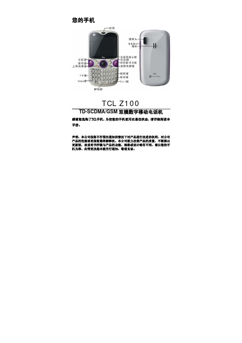
您的手机TCL Z100TD-SCDMA/GSM双模数字移动电话机感谢您选购了TCL手机,为使您的手机使用在最佳状态,请详细阅读本手册。
声明:本公司保留不作预先通知的情况下对产品进行改进的权利,对公司产品的性能说明保留最终解释权。
本公司致力改善产品的质量,不断推出更新版,故说明书所载与产品的功能、规格或设计略有不同,请以您的手机为准,此等更改恕未能另行通知,敬请见谅。
手机按键¾主菜单确认键:触摸感应上下左右可随时移动选择,按中间键确认选项;¾拨号键:向联系人发出呼叫;¾挂机键/开关键:挂断电话/开启或关闭手机;¾上网快捷键:短按此键,可进入上网界面;¾拍照快捷键:短按此键,可进入照像机界面;¾删除键:删除联系人、信息和文件等;¾振动键:短按此键,可激活振动模式。
手机主界面使用手机入门安装与取出电池TCL Z100手机使用锂电池。
在您购买手机时,手机电池没有充电,但有足够的电量供您开机。
请使用厂家提供的原装电池,使用手机前请先正确安装电池。
安装电池打开和合上电池盖:安装和取出电池电量显示电池电量图标显示在手机屏幕的左上角。
当电池电量微弱时,会发出低电告警声,并有提示框。
当电量继续减少到不能支持手机操作时,手机将自动关机。
电池种类 待机时间 通话时间锂离子电池 GSM:150小时TD:170小时GSM:180分钟TD:280分钟注意:电池实际使用时间会因操作方式、网络设置、通话设置的不同而有所不同。
电池充电前,请先仔细阅读下列注意事项。
注意:z当第一次使用电池,请给手机充电至少3小时以上。
z电池长时间没使用,它会自动放电,请在使用前充电。
z电池可以反复充电,但由于电池属于易损耗品,如果正常充电后,手机的待机时间大幅度地降低,请更换新电池。
z请勿强烈碰撞、振动、抛掷电池,否则会引起电池液体渗漏、破损、发热、爆炸或着火。
电池充电TCL Z100手机随机配备一个旅行充电器。
海威尔电器有限公司 T1100L 单列直插 DC DC 电源模块说明书

选型表输入特性输出特性传输特性通用特性产品特性回路供电,过流保护 精度等级(0.3%F .S.) 高线性度(0.1%F .S.)高隔离(输入、输出两端间3kVDC/60s) 极低温漂(35PPM/℃)工业级(工作温度范围:-25℃to +71℃)工作温度-25℃to +71℃运输和存储温度-50℃to +105℃使用环境周围环境存在灰尘、强烈振动、冲击以及对产品元器件有腐蚀的气体可能会对产品造成损坏物理特性外壳材料黑色阻燃耐热塑料封装尺寸SIP 12重量8.0g(Typ.)冷却方式自然空冷产品特性曲线图使用注意事项1.使用前,请仔细阅读说明书,若有疑问,请与本公司技术支持联系;2.请不要将产品安装在危险区域使用;3.产品供电采用直流电源,严禁使用220V 交流电源;4.严禁私自拆装产品,防止设备失效或发生故障;外观尺寸/建议印刷版图引脚功能1(Vin+)电源输入2(Io )电流输出9,10(Iin )电流输入11,12(Vout )电源输出注:尺寸单位:mm[inch]端子截面公差:±0.10[±0.004]未标注之公差:±0.5±0.020]设计参考应用1.功能原理框图2.信号输入、信号输出对应关系示意图(理想状态)3.产品运用接线图注:5.本文数据除特殊说明外,都是在Ta=25℃,湿度<75%RH,输入标称电压和输出额定负载时测得;6.本文所有指标测试方法均依据本公司企业标准;7.以上均为本手册所列产品型号之性能指标,非标准型号产品的某些指标会超出上述要求,具体情况可直接与我司技术人员联系;8.我司可提供产品定制,具体情况可直接与我司技术人员联系;珠海市海威尔电器有限公司公司地址:广东省珠海市高新区创新海岸科技二路10号电话:************销售邮箱:*******************技术支持邮箱:*****************。
百兆以太网ICIP101G规格书
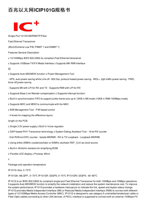
百兆以太⽹ICIP101G规格书Single Port 10/100 MII/RMII/TP/FiberFast Ethernet Transceiver(85nm/Extreme Low PW, PWMT ? and EMIMT ?)Features General Descriptionz 10/100Mbps IEEE 802.3/802.3u compliant Fast Ethernet transceiverz Supports 100Base-TX/FX Media Interface z Supports MII/ RMII Interfacez Supports Auto MDI/MDIX function z Power Management Tool- APS, auto power saving while Link-off - 802.3az, protocol based power saving - WOL+, light traffic power saving - PWD, force-off power saving- Supports MII with LPI for RX and TX - Supports RMII with LPI for RXz Supports Base Line Wander compensation z Supports Interrupt functionz Built in synchronization FIFO to support jumbo frame size up to 12KB in MII mode (10KB in RMII 100Mbps mode)z Supports MDC and MDIO to communicate with the MACz EMI Management Tool - F/W based control- 4 levels for mapping the difference layoutlength on the PCBz Single 3.3V power supply z Built-in Vcore regulatorz DSP-based PHY Transceiver technology z System Debug Assistant Tool - 16 bit RX counter- 9 bit RXError/CRC counter - Isolate MII/RMII - RX to TX Loopback - Loopback MII/RMIIz Using either 25MHz crystal/oscillator or 50MHz oscillator REF_CLK as clock sourcez Built-in 49.9ohm resistors for simplifying BOMz Flexible LED display z Process: 85nmzPackage and operation temperatureIP101G: dice, 0~70℃IP101GA: 48LQFP , 0~70℃ IP101GR: 32QFN, 0~70℃ IP101GRI: 32QFN, -40~85℃IP101G is an IEEE 802.3/802.3u compliant single-port Fast Ethernet Transceiver for both 100Mbps and 10Mbps operations. It supports Auto MDI/MDIX function to simplify the network installation and reduce the system maintenance cost. To improve the system performance, IP101G provides a hardware interrupt pin to indicate the link, speed and duplex status change.IP101G provides Media Independent Interface (MII) or Reduced Media Independent Interface (RMII) to connect with different types of 10/100Mbps Media Access Controller (MAC). IP101G is designed to use category 5 unshielded twisted-pair cable or Fiber-Optic cables connecting to other LAN devices. A PECL interface is supported to connect with an external 100Base-FXfiber optical transceiver. Except good performance, reliability, rich power saving method and extreme low operating current, IP101G provides a serial tool for system designers to complete their projects easily. They are System Debug Assistant Tool and EMI Management Tool.IP101G is fabricated with advanced CMOS (85nm) technology and design is based onIC Plus’s 5th Ethernet-PHY architecture, this feature makes IP101G consumes very low power. Such as in the full load operation (100Mbps_FDX), it only takes below 0.15W. IP101GA / IP101GR&IP101GRI are available in 48LQFP/32QFN, lead-free package.* EMIMT: Patent under apply.Application■ NAS■ Network Printers and Servers ■ IP Set-Top Box ■IP/Smart TV■ Game console■ IP and Video Phone ■ PoE■Telecom Fiber deviceTable Of ContentsTable Of Contents (2)List of Figures (4)List of Tables (5)Revision History (6)Features comparison between IP101G and IP101A/IP101AH (7)Transmit and Receive Data Path Block Diagram (8)1Pin diagram (9)2Dice pad information (11)3Pin description (12)3.1IP101GA pin description (12)3.2IP101GR/GRI pin description (16)4Register Descriptions (19)4.1Register Page mode Control Register (20)4.2MII Registers (20)4.3MMD Control Register (30)4.4MMD Data Register (31)4.5RX Counter Register (34)4.6LED Pin Control Register (35)4.7WOL+ Control Register (36)4.8UTP PHY Specific Control Register (39)4.9Digital IO Pin Control Register (39)5Function Description (41)5.1Major Functional Block Description (41)5.1.1Transmission Description (41)5.1.2MII and Management Control Interface (42)5.1.3RMII Interface (43)5.1.4Flexible Clock Source (45)5.1.5Auto-Negotiation and Related Information (45) 5.1.6Auto-MDIX function (46)5.2PHY Address Configuration (46)5.3Power Management Tool (47)5.3.1Auto Power Saving Mode (47)5.3.2IEEE802.3az EEE (Energy Efficient Ethernet) (48) 5.3.3Force power down (48)5.3.4WOL+ operation mode (48)5.4LED Mode Configuration (52)5.5LED Blink Timing (52)5.6Repeater Mode (52)5.7Interrupt (52)5.8Miscellaneous (52)5.9Serial Management Interface (53)5.10Fiber Mode Setting (54)5.11Jumbo Frame (54)6Layout Guideline (55)6.1General Layout Guideline (55)6.2Twisted Pair recommendation (55)7Electrical Characteristics (56)7.1Absolute Maximum Rating (56)7.2DC Characteristics (56)7.3Crystal Specifications (57)7.4AC Timing (58)7.4.1Reset, Pin Latched-in, Clock and Power Source (58) 7.4.2MII Timing (59)7.4.3RMII Timing (60)7.4.4SMI Timing (61)7.5Thermal Data (61)8Order Information (62)9Physical Dimensions (63)9.148-PIN LQFP (63)9.232-PIN QFN (64)List of FiguresFigure 1 Flow chart of IP101G (8)Figure 2 IP101GA 48 Pin Diagram (9)Figure 3 IP101GR/GRI 32 Pin Diagram (10)Figure 4 IP101G dice pad information (11)Figure 5 LPI transition (43)Figure 6 IP101G/GA/GR/GRI MII Mode with LPI transition Block Diagram (43) Figure 7 IP101G/GA/GR/GRI MII Mode without LPI transition Block Diagram (43) Figure 8 IP101G RMII Mode with internal clock Block Diagram (44)Figure 9 IP101G RMII Mode with external clock Block Diagram (44)Figure 10 IP101G RMII Clock Application Circuit (45)Figure 11 IP101G link speed and EEE ability programming guide (46)Figure 12 PHY Address Configuration (47)Figure 13 Magic Packet Format (49)Figure 14 Sleep or wake up automatically programming guide (50)Figure 15 MAC control sleep or wake up programming guide (51)Figure 16 MDC/MDIO Format (53)Figure 17 IP101G Fiber Mode Setting (54)Figure 18 Reset, Pin Latched-In, Clock and Power Source Timing Requirements (58) Figure 19 MII Transmit Timing Requirements (59)Figure 20 MII Receive Timing Specifications (59)Figure 21 RMII Transmit Timing Requirements (60)Figure 22 RMII Receive Timing Specifications (60)Figure 23 SMI Timing Requirements (61)Figure 24 48-PIN LQFP Dimension (63)Figure 25 32-PIN QFN Dimension (64)List of TablesTable 1 Features comparison between IP101G and IP101A/IP101AH (7)Table 2 Register Map (19)Table 3 Flexible Clock Source Setting (45)Table 4 PHY Address Configuration (47)Table 5 WOL+ operation mode (49)Table 6 LED Mode 1 Function (52)Table 7 LED Mode 2 Function (52)Table 8 LED Blink Timing (52)Table 9 SMI Format (53)Table 10 DC Characteristics (56)Table 11 I/O Electrical Characteristics (56)Table 12 Pin Latched-in Configuration Resistor (57)Table 13 Crystal Specifications (57)Table 14 Reset, Pin Latched-in, Clock and Power Source Timing Requirements (58) Table 15 MII Transmit Timing Requirements (59)Table 16 MII Receive Timing Specifications (59)Table 17 RMII Transmit Timing Requirements (60)Table 18 RMII Receive Timing Specifications (60)Table 19 SMI Timing Requirements (61)Table 20 Thermal Data (61)Table 21 Part Number and Package (62)Revision HistoryRevision # Change DescriptionIP101G-DS-R01 Initial release.IP101G-DS-R01-20120622 Add 30 seconds into the definition for register WOL_PLUS_TIMER_SEL. IP101G-DS-R01-20120629 Add the symbol SC (Self Clear) for PHY MII register 0.15 Reset and 0.9Restart Auto-Negotiation.IP101G-DS-R01-20120709 1) Add LED mode 2 in the pin description and function description.2) Correct the table of LED Blink Timing.3) Add more description of PHY Address Configuration and IEEE 802.3az.4) Add ESD reliability of Absolute Maximum Rating.5) Correct the typo of function description for Auto Power Saving Mode.6) Change register P16R16[10] description from HEART_BEAT_EN toReserved.IP101G-DS-R01-20120719 Correct the table of Register Map for page selection.IP101G-DS-R01-20120726 1) Add more description of Register RX2TX_LPBK P1R23[13] for Rx to Txloopback test.2) Add more description on Fiber Mode Setting and latched-in pin signalson AC Timing.3) Add IP101AH into the table of features comparison.IP101G-DS-R01-20120808 1) Correct the I/O type of IP101GA pin description to O(Ouput) for pin24RXER.2) Change the pin name from DVDD33_IO to VDDIO.IP101G-DS-R01-20120821 1) Change the default value of register P16R27 from 0x0022 to 0x0012.2) Remove I/O Slew Rate Control Register.3) Change the register location RMII_WITH_ER from P16R29[0] toP16R29[7].IP101G-DS-R01-20120927 1) Add more description of low power idle (LPI) state in MII and RMIImodes.2) Correct the typo of Physical Dimensions.IP101G-DS-R01-20121101 Change the LED blink timing from “On 80ms -> Off (20~40)ms” to “On 26ms-> Off 78ms”.IP101G-DS-R01-20121113 Add more function description to support Jumbo Frame.IP101G-DS-R01-20121127 Change the LED mode function as same as IP101A.IP101G-DS-R01-20121224 Add the notice that does not let these PHY address pins floating for thelatched-in settings after the power is ready.IP101G-DS-R01-20130206 Change the AC timing Tclk_MII_rdy in Table 14 from 10ms Min. to 10ms Max. IP101G-DS-R01-20130312 1) Add more Min. and Max value on the AC Timing table.2) Add thermal data on the Table 20.IP101G-DS-R01-20130507 Add LED Pin Driving Control RegisterIP101G-DS-R01-20130621 Add GRI 2.5V I/O power supplyDisclaimerThis document probably contains the inaccurate data or typographic error. In order to keep this document correct, IC Plus reserves the right to change or improve the content of this document.Features comparison between IP101G and IP101A/IP101AHTable 1 Features comparison between IP101G and IP101A/IP101AHProduct Name IP101GR IP101G IP101GA IP101A IP101AH Package Type 32pin QFN Dice 48pin LQFP48pin LQFP REGOUT(1) Output Voltage and location 1.0V, pin28 1.0V, pad5and pad111.0V, pin82.5V, pin32REGIN Input Voltage and location NA(2) 1.0V,pad23and pad26NA 2.5V,pin8RMII mode setting Pin4 Pad18 Pin1 Pin1 and pin44Fiber mode setting: Fiber FXSD signal: Pin19Pin1Pad39Pad13Pin22Pin43NA Pin24 and pin48Pin37Number of LED 2 4 4 5LED mode 1 and 2 1 and 2LED Blink Timing On 26ms -> Off 78ms On 26ms -> Off 78msPHY address number(3) Single: 0 ~ 1Multi: 2 ~ 31Single: 0 ~ 7Multi: 8 ~ 31Single: 0 ~ 31Center-tap of transformer Do not connect to any power 2.5V input powerBuilt-in 49.9ohm resistors Yes NoPowerconsumption ~150mW ~480mW Process 85nm0.25µmIEEE 802.3az Yes No10Base TX amplitude ~1.75V (10Base-Te) ~2.5V(10Base-T) WOL+ (Wake On LAN Plus) Yes NoAnalog OFF Yes No16 bit RX counter Yes No9 bit RXER/CRC counter Yes NoRX to TX Loopback Yes NoLoopback MII/RMII Yes YesSNI mode No YesNote 1: Regulator voltage output is for internal use only. Do not supply to any other device.Note 2: Not available for this function. The 1.0V is supplied by the regulator that built-in the chip. Note 3: Do not let these PHY address pins floating for the latched-in settings after the power is ready.Transmit and Receive Data Path Block DiagramFigure 1 Flow chart of IP101G1Pin diagramRXER CRS/LEDMODRXDV/CRS_DV/FX_HEN X1X2RXD2RXD3RXCLK/50M_CLKO DGNDRXD0NCRESET_N IP101GA (LQFP-48)242322212019181716NC NC TXER/FXSDNC Those pins in "blue "are different from IP101A. NC Note:RXD1INTRNC DGNDNC LED3/PHY_AD3VDDIOFigure 2 IP101GA 48 Pin DiagramIP101GR/GRI (VQFN-32)(GND on bottom of chip)RXD3TXCLK/50M_CLKI RXCLK/50M_CLKO LED0/PHY_AD0LED3/PHY_AD3161514131211109 RESET_NISET REGOUT MDI_TN MDI_TP MDI_RP MDI_RN RXD2AVDD33 Figure 3 IP101GR/GRI 32 Pin Diagram2Dice pad informationIC LogoPad 1Pad 44Pad 11Pad 45Pad 24Pad 31Pad 12Pad 22Pad 23REGINPHYAD_LED028PHYAD_LED129VSS30PHYAD_LED231PHYAD_LED332VDDIO 33RX_CLK REGOUT 34VSSIO RESET_N 35RXD[3]TXER_FXSD 36RXD[2]VSSIO 37RXD[1]15X138RXD[0]16X239RXDV_FIBMOD 17INTR40CRS18COL_RMII 41RXER_INTR 19TX_EN 4220TXD[3]21TXD[2]22TXD[1]23REGINFigure 4 IP101G dice pad information3 Pin descriptionType DescriptionType DescriptionLI Latched Input in power up or reset PD Internal Pull-Down 104K ? I/O Bi-directional input and outputPUInternal Pull-Up 222K ?I Input Hi-Z High impedanceO Output P Power OD Open Drain3.1 IP101GA pin descriptionIP101GAPin no. LabelType Reset StateDescriptionSerial Management Interface Pins 25 MDC I Hi-Z Management Data Interface Clock: This pin provides a clock reference to MDIO. The clock rate can be up to 2.5MHz.26 MDIO I/O (PU) I (PU)Management Data interface Input/Output:Thefunction of this pin is to transfer management informationbetween PHY and MAC.MII/RMII Pins2 TXEN I (PD) I (PD)Transmit Enable or Signal Detect.43 TXER/FXSD I (PD) I (PD)Transmit Error or FXSD:This is a dual-function pin which is determined by themedia type selection. If RXDV/CRS_DV/FX_HEN islatched as “0 (default)” upon reset, the TP interface isselected and its function as TXER. If the fiber interface is selected, this pin’s function as FXSD.FXSD:0: Fiber link down; 1: Fiber link upTransmit Enable:TXEN TXER Description 1 1 Transmission errorpropagation.0 1 Combine TXD[3:0] that equalto 0001 for request PHY to enter LPI mode.1 0 0 0Normal operationThis pin TXER must be either floating or connecting to GND in RMII mode.7 TXCLK/50M_CLKI I/O Hi-Z Transmit Clock output or 50M clock input:In MII mode, this pin provides a continuous 25MHz clock at 100Base-TX and 2.5MHz at 10Base-T . In RMII mode, a 50Mhz clock should input to this pin for the timing reference of the internal circuit. 3,4,5,6 TXD[3:0] I Hi-Z Transmit Data Input:IP101GAPin no.LabelType ResetDescriptionStateIn MII mode, TXD[3:0] is synchronous to TXCLK.In RMII mode, TXD[1:0] is synchronous to 50M_CLKI.22 RXDV/CRS_DV/ FX_HEN O/LI (PD) I (PD)Receive Data Valid or Media Type Selection:FX_HENThe input state is latched upon reset to determine whether TP or fiber interface is selected. If it is at logic “0” (default) state upon reset, the TP interface is selected; otherwise the fiber interface is selected. RXDV/CRS_DVIn MII mode, this pin indicates the Receive Data Valid function.In RMII mode, this pin indicates the Carrier Sense and Receive Data Valid function.16 RXCLK/ 50M_CLKO O Hi-Z Receive Clock:In MII mode, this pin provides 25MHz for 100BT or2.5MHz for 10BT.In RMII mode, this pin output a 50 MHz clock for the timing reference of MAC side.18,19, 20,21 RXD[3:0] O Hi-Z Receive Data: In MII mode, RXD[3:0] is synchronous to RXCLK.In RMII mode, RXD[1:0] is synchronous to 50M_CLKI.24 RXER O Hi-Z Receive error:RXDV RXER Description1 1 Decoding error of thereceived signal0 1 Combine RXD[3:0] equal to0001 indicates PHY isreceiving LPI.1 0 0 0Normal operationThis pin RXER is an optional input for MAC/CPU device.1 COL/RMII O/LI (PD) I (PD)Collision Detected:During the normal operation, thispin outputs a high status signal it means collision isdetected.RMII Mode Selection: During the power on reset, thispin status is latched to determine what kind MAC interface will be used. Logic “1” is for RMII mode and logic “0” is for MII mode.23 CRS/LEDMOD O/LI (PD) I (PD)Carrier Sense: When signal output from this pin is highindicates the transmission or reception is in process andat low status means the line is in idle state.LEDMOD: During power on reset, this pin status is latched to determine which either LED mode 1 or 2is selected, please refer to the LED pins description.Cable Transmission Interface 34,33 MDI_TP MDI_TN I/O I/O Hi-Z Transmit Output Pair: Differential pair shared by100Base-TX and 10Base-T modes. When configured as100Base-TX, output is an MLT-3 encoded waveform. When configured as 10Base-T , the output is ManchesterIP101GAPin no. Label Type Reset DescriptionStatecode.31,30 MDI_RPMDI_RN I/OI/OHi-Z Receive Input Pair: Differential pair shared by 100Base-TX and 10Base-T modes.Clock and Miscellaneous Pins47 X2 O O 25MHz Crystal Output: Connects to crystal to providethe 25MHz output. It must be left open when X1 is drivenwith an external 25MHz oscillator.46 X1 I I 25MHz Crystal Input: Connects to crystal to provide the25MHz crystal input. If a 25MHz oscillator is used,connect X1 to the oscillator’s output. If a 50MHz clock isapplied to pin7 TXCLK/50M_CLKI, X1 must beconnected to GND or AGND33.42 RESET_N I I(PU)RESET_N: Enable a low status signal will reset the chip. For a complete reset function. 25MHz clock (x1) must be active for a minimum of 10 clock cycles before the rising edge of RESET_N. Chip will be able to operate after 2.5ms delay of the rising edge of RESET_N. The 2.5ms extension is to ensure the stability of system power.28 ISET I I Bandgap Circuit Resistor: This pin should beconnected to GND via a 6.19K? (1%) resistor to definethe standard current of the internal circuit.48 INTR OD Hi-Z Interrupt: Programmable Interrupt Output, this is anopen drain output, and an external pulled-up resistor isneeded for normal mode operation. Another operationmode is Rx to Tx loopback debugging test (reflect onRegister P1R23[13] RX2TX_LPBK) when connect INTRpin to GND.9 LED0/PHY_AD0 O/LI Hi-Z LED 0 and PHY Address [0]LED 0LED mode1 2LED0Link Link/ACT(blinking)10 LED1/PHY_AD1 O/LI Hi-Z LED 1 and PHY Address [1]LED1LED mode1 2LED1Duplex Duplex /COL (blinking)12 LED2/PHY_AD2 O/LI Hi-Z LED 2 and PHY Address [2]LED2LED mode1 2LED210M Link /ACT10M Link13 LED3/PHY_AD3 O/LI(PD) Hi-Z LED 3 and PHY Address [3]LED3LED mode1 2LED3100M Link /ACT 100M Link27 TEST_ON I I Test Enable: Set this pin to high to enable Test mode.IP101GAPin no. Label Type Reset DescriptionState(PD) (PD)For normal operation, this pin doesn’t need to be connected.Power and Ground32 NC -- -- It’s a NC pin.8 REGOUT P P Regulator Power Output: This is a regulator power output. A 10uF and 0.1uF should be connected to this pinto filter the power noise.14 VDDIO P P Digital Power input:Either 3.3V or 2.5V for I/O power supply.36 AVDD33 P P 3.3V Analog power input: This is a 3.3V power supply for analog circuitry, and it should be decoupled carefully.35 AGND33 P P Ground.29 AGND1V P P Ground45,11,17 DGND P P Ground.3.2 IP101GR/GRI pin descriptionIP101GR/GRIPin no. Label Type ResetStateDescriptionSerial Management Interface Pins22 MDC I Hi-Z Management Data Interface Clock: This pin provides a clock reference to MDIO. The clock rate can be up to2.5MHz.23 MDIO I/O(PU)I(PU)Management Data interface Input/Output:Thefunction of this pin is to transfer management informationbetween PHY and MAC.MII/RMII Pins5 TXEN I(PD)I(PD)Transmit Enable or Signal Detect.1 TXER/FXSD I(PD)I(PD)Transmit Error or FXSD:This is a dual-function pin which is determined by the media type selection. If RXDV/CRS_DV/FX_HEN is latched as “0 (default)” upon reset, the TP interface is selected and its function as TXER. If the fiber interface is selected, this pin’s function as FXSD.FXSD:0: Fiber link down; 1: Fiber link upTransmit Enable:TXEN TXER Description1 1 Transmissionerrorpropagation.0 1 CombineTXD[3:0]thatequalto 0001 for request PHY toenter LPI mode.1 00 0Normal operationThis pin TXER must be either floating or connecting toGND in RMII mode.10 TXCLK/50M_CLKI I/O Hi-Z Transmit Clock output or 50M clock input: In MII mode,this pin provides a continuous 25MHz clockat 100Base-TX and 2.5MHz at 10Base-T.In RMII mode, a 50Mhz clock should input to this pin forthe timing reference of the internal circuit.6,7,8,9 TXD[3:0] I Hi-Z Transmit Data Input:In MII mode, TXD[3:0] is synchronous to TXCLK.In RMII mode, TXD[1:0] is synchronous to 50M_CLKI.19 RXDV/CRS_DV/FX_HEN O/LI(PD)I(PD)Receive Data Valid or Media Type Selection:FX_HENThe input state is latched upon reset to determinewhether TP or fiber interface is selected. If it is at logic“0” (default) state upon reset, the TP interface isselected; otherwise the fiber interface is selected.RXDV/CRS_DVIn MII mode, this pin indicates the Receive Data ValidIP101GR/GRIPin no.LabelType ResetDescriptionStatefunction.In RMII mode, this pin indicates the Carrier Sense and Receive Data Valid function.14 RXCLK/ 50M_CLKO O Hi-Z Receive Clock:In MII mode, this pin provides 25MHz for 100BT or2.5MHz for 10BT.In RMII mode, this pin output a 50 MHz clock for the timing reference of MAC side.15,16, 17,18 RXD[3:0] O Hi-Z Receive Data: In MII mode, RXD[3:0] is synchronous to RXCLK. In RMII mode, RXD[1:0] is synchronous to 50M_CLKI.21 RXER/INTR_32 O/ODHi-Z The multiplex function of this pin is set by the registerSEL_INTR32, page 16,29[2]. The default function is RXER.Receive error:RXDV RXER Description 1 1 Decoding error of thereceived signal0 1 Combine RXD[3:0] equal to0001 indicates PHY is receiving LPI.1 0 0 0Normal operationThis pin RXER is an optional input for MAC/CPU device.Interrupt: Programmable Interrupt Output, this is an open drain output, and an external pulled-up resistor is needed.4 COL/RMII O/LI (PD) I (PD)Collision Detected:During the normal operation, thispin outputs a high status signal it means collision isdetected.RMII Mode Selection: During the power on reset, thispin status is latched to determine what kind MAC interface will be used. Logic “1” is for RMII mode and logic “0” is for MII mode.20 CRS/LEDMOD O/LI (PD) I (PD)Carrier Sense:When signal output from this pin is highindicates the transmission or reception is in process andat low status means the line is in idle state.LEDMOD: During power on reset, this pin status is latched to determine which either LED mode 1 or 2is selected, please refer to the LED pins description.Cable Transmission Interface 30,29 MDI_TP MDI_TN I/O I/O Hi-Z Transmit Output Pair: Differential pair shared by100Base-TX and 10Base-T modes. When configured as100Base-TX, output is an MLT-3 encoded waveform. When configured as 10Base-T , the output is Manchester code.27,26 MDI_RP MDI_RN I/O I/O Hi-Z Receive Input Pair: Differential pair shared by100Base-TX and 10Base-T modes.Clock and Miscellaneous PinsIP101GR/GRIPin no. Label Type Reset DescriptionState3 X2 O O 25MHz Crystal Output: Connects to crystal to providethe 25MHz output. It must be left open when X1 is drivenwith an external 25MHz oscillator.2 X1 I I 25MHz Crystal Input: Connects to crystal to provide the25MHz crystal input. If a 25MHz oscillator is used,connect X1 to the oscillator’s output. If a 50MHz clock isapplied to pin10 TXCLK/50M_CLKI, X1 must beconnected to GND.32 RESET_N I I(PU)RESET_N: Enable a low status signal will reset the chip. For a complete reset function. 25MHz clock (x1) must be active for a minimum of 10 clock cycles before the rising edge of RESET_N. Chip will be able to operate after 2.5ms delay of the rising edge of RESET_N. The 2.5ms extension is to ensure the stability of system power.25 ISET I I Bandgap Circuit Resistor: This pin should beconnected to GND via a 6.19K? (1%) resistor to definethe standard current of the internal circuit.11 LED0/PHY_AD0 O/LI Hi-Z LED 0 and PHY Address [0]LED 0LED mode1 2LED0Link Link/ACT(blinking)12 LED3/PHY_AD3 O/LI(PD) Hi-Z LED 3 and PHY Address [3]LED3LED mode1 2LED3100M Link /ACT 100M Link24 TEST_ON I(PD)I(PD)Test Enable: Set this pin to high to enable Test mode.For normal operation, this pin doesn’t need to beconnected.Power and Ground28 REGOUT P P Regulator Power Output: This is a regulator power output. A 10uF and 0.1uF should be connected to this pinto filter the power noise.13 VDDIO P P Digital Power input:IP101GR/GRI: Either 3.3V or 2.5V for I/O power supply.31 AVDD33 P P 3.3V Analog power input: This is a 3.3V power supply for analog circuitry, and it should be decoupled carefully.Bottom PAD GND PPGround.4 Register DescriptionsTable 2 Register MapPage Register Description Default NoteRegister 0x0010X 20 PageControlRegister 0x3100-- 0 ControlRegister 0x7849-- 1 Status-- 2 PHY Identifier 1 Register 0x0243-- 3 PHY Identifier 2 Register 0x0C54Advertisement Register 0x01E1-- 4 Auto-Negotiation-- 5 Auto-Negotiation Link Partner Ability Register 0x0000-- 6 Auto-Negotiation Expansion Register 0x0004-- 7 Auto-Negotiation Next Page Transmit Register 0x2001-- 8 Auto-Negotiation Link Partner Next Page Register 0x0000-- 13 MMD Access Control Register 0x0000-- 14 MMD Access Address Data Register 0x000016 16 PHY Specific Control Register 0x000216 17 PHY Interrupt Ctrl/Status Register 0x0F0016 18 PHY Status Monitoring Register 0x020816 26 Digital IO Pin Driving Control Register 0x124916 27 Digital IO Pin Driving Control Register 0x001216 28 LED Pin Driving Control Register 0x000116 29 Digital I/O Specific Control Register 0x008216 30 PHY MDI/MDIX Control and Specific Status Register 0x0000 -- MMD 3.0 PCS Control 1 Register 0x0000-- MMD 3.1 PCS Status 1 Register 0x0000-- MMD 3.20 EEE Capability Register 0x0002-- MMD 3.22 EEE Wake Error Count Register 0x0000-- MMD 7.60 EEE Advertisement Register 0x0002-- MMD 7.61 EEE Link Partner Ability Register 0x00001 17 PHY Specific Control Register 0x00001 18 RX CRC Error Counter Register 0x00001 22 Linear Regulator Output Control Register 0x20201 23 UTP PHY Specific Control Register 0x80002 18 RX Packet Counter Register 0x00003 16 LED Mode Control Register 0x00004 16 WOL+ Control Register 0x5F404 22 Digital IO Pin Driving Control Register 0x40005 16 PHY WOL+ MAC Address Register 0x00008 17 RX Counter Control Register 0x7000。
CCL300DC3-TD1中文资料
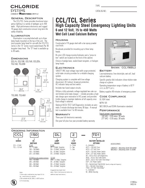
ACCESSORIESLMSHELF = Mounting Shelf 300-450W MXSHELF = Mounting Shelf 72-200WOrdering InformationSERIES DC WATTAGE HEADS HEADS OPTIONS 1CCL = 6 Volt 6 Volt6 Volt3 = Three A = Ammeter 2TCL = 12 Volt75 = 75 Watts DY = 8 Watt, Tungsten 2 = Two ACF1 = 120 VAC Fuse 100 = 100 Watts DA = 18 Watt, Tungsten 1 = OneACF2 = 277 VAC Fuse 150 = 150 Watts DL = 25 Watt, Tungsten ACP1 = 120 VAC Power Switch 225 = 225 WattsDC = 30 Watt, Tungsten ACP2 = 277 VAC Power Switch AD = ACCU-TEST Self-Diagnostics 12 Volt (Includes standard voltmeter)12 VoltADAL = ACCU-TEST with Alarm150 = 150 Watt DNY = 12 Watt, Tungsten ADTD = ACCU-TEST with Time Delay 3200 = 200 Watt DE = 28 Watt, Tungsten DCP = DC Power Switch300 = 300 Watt DK = 25 Watt, Tungsten EX = Special Input Transformer (Specify voltage and frequency)450 = 450 WattDG = 30 Watt, TungstenTD1 = 120 VAC Time Delay 3TTD2 = 277 VAC Time Delay 3(Suggested lamp heads listedV = Voltmeter 2above. Refer to the Accessories Section for W = White Housingadditional lamp head choices.)CCL15016.0”(40.6 cm)TCL300, TCL4506.0”(15.2 cm)7.6”(19.3 cm)12.0”(30.5 cm)27.0”(12.7 cm)6.0”(15.2 cm)7.6”(19.3 cm)12.0”(30.5 cm)Notes:1) Some option combinations may impact UL list-ing. consult factory for specifics.2) Not available witj AD, ADAL, or ADTD options.3) 15 minute delay.元器件交易网Housing18 gauge steel housing with a tan epoxy powder coat finish.Knockouts provided for mounting up to three lamp heads.The suggested lamp head is the “D” Series round sealed beam Par 36 tungsten. To order lamp heads other than the suggested “D” head, refer to Chloride Accessories Section..Suggested SpecificationFurnish and install Chloride Systems emergency lighting unit model ________. The unit shall be constructed to meet Underwriter’s Laboratories, Inc. Standard #924and the National Electrical Code (NEC).INSTALLATION AND OPERATION -Unit shall be easily field connected to a 120 or 277 VAC, 60 hertz, unswitched power source. Installation must comply with the NEC as well as other applicable codes. Upon utility power failure or brownout, the unit shall automatically transfer to battery power and maintain the required illumina-tion level for a minimum period of 90 minutes. Upon restoration of utility power, the charger shall restore the battery to full charge within UL 924 requirements follow-ing a rated discharge of not more than 90 minutes.CHARGER -Product shall utilize a fully automatic, voltage regulated, two-rate current limited solid-state charger. The charging system shall maintain the battery at full capacity without the need for periodic exercising or equalization. The following features shall be standard: Low voltage disconnect (LVD), brownout protection and AC lockout.BATTERY -The battery shall be a low maintenance, free electrolyte, wet cell, lead calcium battery. The lead calcium battery shall provide trouble-free operation in temperatures up to 85°F (30°C).HOUSING -The unit housing shall be constructed of 18 gauge steel with a tan epoxy powder coat finish.Chloride SystemsISO8C1063R49/02 IH272 West Stag Park Service Road •Burgaw NC 28425Telephone: (910) 259 1000 •Facsimile: (800) 258 Lamp Head Photometrics(For DL, suggested head for CCL)(For DK, suggested head for TCL)Vertical203050100Up 2010feet 010Down 20.2.1406070.31.5Horizontal203050100Left 2010feet 010Right 20.2.1406070.31.5203050100Up 2010feet 010Down 20Photometric No. 3406070801.3.2.1.5Horizontal203050100Left 3010feet 01020Right 301.3.2.120.540607080。
TCL100DE1-TTD2中文资料

ACCESSORIESLMSHELF = Mounting Shelf 300-450W MXSHELF = Mounting Shelf 72-200WOrdering InformationSERIES DC WATTAGE HEADS HEADS OPTIONS 1CCL = 6 Volt 6 Volt6 Volt3 = Three A = Ammeter 2TCL = 12 Volt75 = 75 Watts DY = 8 Watt, Tungsten 2 = Two ACF1 = 120 VAC Fuse 100 = 100 Watts DA = 18 Watt, Tungsten 1 = OneACF2 = 277 VAC Fuse 150 = 150 Watts DL = 25 Watt, Tungsten ACP1 = 120 VAC Power Switch 225 = 225 WattsDC = 30 Watt, Tungsten ACP2 = 277 VAC Power Switch AD = ACCU-TEST Self-Diagnostics 12 Volt (Includes standard voltmeter)12 VoltADAL = ACCU-TEST with Alarm150 = 150 Watt DNY = 12 Watt, Tungsten ADTD = ACCU-TEST with Time Delay 3200 = 200 Watt DE = 28 Watt, Tungsten DCP = DC Power Switch300 = 300 Watt DK = 25 Watt, Tungsten EX = Special Input Transformer (Specify voltage and frequency)450 = 450 WattDG = 30 Watt, TungstenTD1 = 120 VAC Time Delay 3TTD2 = 277 VAC Time Delay 3(Suggested lamp heads listedV = Voltmeter 2above. Refer to the Accessories Section for W = White Housingadditional lamp head choices.)CCL15016.0”(40.6 cm)TCL300, TCL4506.0”(15.2 cm)7.6”(19.3 cm)12.0”(30.5 cm)27.0”(12.7 cm)6.0”(15.2 cm)7.6”(19.3 cm)12.0”(30.5 cm)Notes:1) Some option combinations may impact UL list-ing. consult factory for specifics.2) Not available witj AD, ADAL, or ADTD options.3) 15 minute delay.元器件交易网Housing18 gauge steel housing with a tan epoxy powder coat finish.Knockouts provided for mounting up to three lamp heads.The suggested lamp head is the “D” Series round sealed beam Par 36 tungsten. To order lamp heads other than the suggested “D” head, refer to Chloride Accessories Section..Suggested SpecificationFurnish and install Chloride Systems emergency lighting unit model ________. The unit shall be constructed to meet Underwriter’s Laboratories, Inc. Standard #924and the National Electrical Code (NEC).INSTALLATION AND OPERATION -Unit shall be easily field connected to a 120 or 277 VAC, 60 hertz, unswitched power source. Installation must comply with the NEC as well as other applicable codes. Upon utility power failure or brownout, the unit shall automatically transfer to battery power and maintain the required illumina-tion level for a minimum period of 90 minutes. Upon restoration of utility power, the charger shall restore the battery to full charge within UL 924 requirements follow-ing a rated discharge of not more than 90 minutes.CHARGER -Product shall utilize a fully automatic, voltage regulated, two-rate current limited solid-state charger. The charging system shall maintain the battery at full capacity without the need for periodic exercising or equalization. The following features shall be standard: Low voltage disconnect (LVD), brownout protection and AC lockout.BATTERY -The battery shall be a low maintenance, free electrolyte, wet cell, lead calcium battery. The lead calcium battery shall provide trouble-free operation in temperatures up to 85°F (30°C).HOUSING -The unit housing shall be constructed of 18 gauge steel with a tan epoxy powder coat finish.Chloride SystemsISO8C1063R49/02 IH272 West Stag Park Service Road •Burgaw NC 28425Telephone: (910) 259 1000 •Facsimile: (800) 258 Lamp Head Photometrics(For DL, suggested head for CCL)(For DK, suggested head for TCL)Vertical203050100Up 2010feet 010Down 20.2.1406070.31.5Horizontal203050100Left 2010feet 010Right 20.2.1406070.31.5203050100Up 2010feet 010Down 20Photometric No. 3406070801.3.2.1.5Horizontal203050100Left 3010feet 01020Right 301.3.2.120.540607080。
特克达TCL-DC系列工业级DC DC转换器说明书

Industrial DC/DC-ConverterTCL-DC Series, 24 to 60 WattFeatures◆ Ultra-wide input voltage range ◆ Output voltage adjustable◆ Overload and short circuit protection ◆ Low ripple and noise ◆ I/O isolation 1500 VDC ◆ Compact, slim plastic case◆ Reliable snap-on mount on DIN-rail ◆ Bracket for wall mount included ◆ 3-year product warrantyIn the TCL range of DIN-rail power supplies are 6 models for DC input voltage avail-able. The wide input ranges of 9.5–18 VDC resp. 18–75 VDC means these models can be operated from all popular DC supply voltage systems.With tightly regulated output voltage these DC/DC converters provide a reliable power source for sensitive loads in industrial process controls, factory automation and other equipment exposed to a critical industrial environment. Further applica-tions for these converters are isolation of a specific load or refreshing the 24 V bus voltage. Easy installation is provided with snap-on mounting on DIN-rails and detachable screw terminal block.UL 508C BSchemeInput power at no load 1.0 Watt max.Start-up voltage/under voltage shut down TCL 012 model:8.4 VDC / 7.6 VDCTCL 024 & TCL 060 models:17.2 VDC / 15.7 VDCReverse polarity protection by internal fuseEfficiency 86 % typ.Output voltage adj. range 5 VDC model: 5.0 – 5.25 VDC12 VDC models: 12.0 – 15.0 VDC24 VDC models: 24.0 – 28.0 VDCRegulation – Input variation Vin min. to Vin max.0.5 % max– Load variation 0...100%0.5 % maxRipple and noise (20 MHz bandwidth)<50 mV pk-pkElectronic short circuit protection current limitation at 110 % typ.(constant current, automatic recovery) Overvoltage protection, trigger point 5 VDC model: <6.5 V12 VDC models:<24 V24 VDC models: <42 VTemperature ranges – Operating–25°C to +70°C max.– Storage (non operating)–25°C to +85°CTemperature derating TCL 012 & TCL 024 models: 1.5 %/K above +50°CTCL 060 models: 2.0 %/K above +40°CHumidity (non condensing)95 % rel. H max.Temperature coefficient 0.02 %/KSwitching frequency 55 – 180 kHz depending on load(frequency modulation)Isolation voltage (60 sec.)– Input/Output 1500 VDCReliability, calculated MTBF at +25°C (according to IEC 61709)>2.5 Mio hSafety standards – Information technology equipment IEC 60950-1, EN 60950-1 (output SELV),UL Std. 60950-1 (2nd Edition) +Am1:2011,CAN/CSA-C22.2 No. 60950-1-07 +Am1:2011 – Industrial control equipment UL 508– Electronic equipment for power installation EN 50178– Electrical equipment for machines EN 60204Safety approvals – UL approval -> certificationsUL 508C listed, CSA C22.2 No.14 File e210002 Electromagnetic compatibility (EMC), emissions EN 61000-6-3– Conducted RI suppression on input EN 55022 class B– Radiated RI suppression EN 55022 class BElectromagnetic compatibility (EMC), immunity EN 61000-6-2– Electrostatic discharge (ESD)EN 61000-4-2 4 kV / 8 kV– Radiated RF field immunity EN 61000-4-3 10 V/m– Electrical fast transient / burst immunity EN 61000-4-4 Level 3– Surge immunity EN 61000-4-5 Level 3– Immunity to conducted RF disturbances EN 61000-4-6 10 VrmsEnvironmental compliance – Reach /info/reach-declaration.pdf – RoHS RoHS directive 2011/65/EUCase protection IP 20 (IEC 60529)Enclosure material plastic UL 94V-0 ratedMounting DIN-rails as per EN 50022-35x15/7.5(snap-on with self-locking spring)bracket for wall/chassis mount included Installation instructions /overview/tcl-dcAll specifications valid at nominal input voltage, full load and +25 °C after warm-up time unless otherwise stated.Rev. April 9, 2019Page 3 of 3adjustDimensions in [mm], () = InchTolerances: ±0.5 (±0.02)Case DimensionsWall Mounting BracketInstead on a DIN-rail, the modules can be also mounted on a chassis or wall with help of a mounting bracket which is supplied as standardwith each ConverterDC-ON LEDadjustTCL 012 and TCL 024 modelsTCL 060 model。
电路图纸-TCL彩电IC中文名称及参数资料 (105种)

信号输出
4
PF2
相为滤波器 3.8 16
TD
高音数字- 2.2
2
模拟转换输
出
5
PF3
相为滤波器 3.8 17
BLD
左右声道平 2.9
3
衡数字-模
拟转换输出
6
PF4
相为滤波器 3.8 18
RT
右声道高音 3.8
4
变频器校正
7
GND
接地点
0 19
RB
右声道低音 3.8
变频器校正
8
LT
左声道高音 3.8 20
序
符号
功能
直流 序
符号
功能
直流电
号
电压 号
压(V)
(V)
1
Vcc1
电源 1
11 6
FB
反馈输入
9.4
2
IN
输入信号
4.9 7
GND
地
0
3
Mute
静音控制输入
08
OUT
信号输出
9.5
4
VOL
音量控制输入 0.6 9
Vcc2
电源 2
18
5
Filter
外接滤波器
9.3
AN5891K 音频处理集成电路
概述:AN5891K 是 I2C 总线控制的音频处理器,具有以下特点:受 I2C 总线控制;AGC
为复位输入端口,外接电阻电容组成的复位电路。VCC(40 脚)和 VSS(20 脚)为供电端
口,分别接+5V 电源的正负端。P0~P3 为可编程通用 I/O 脚,其功能用途由软件定义,在本
设计中,P0 端口(32~39 脚)被定义为 N1 功能控制端口,分别与 N1 的相应功能管脚相连
tcl脚本语言中文详解
T C L用法祥述一TCL语法1 脚本、命令和单词符号一个TCL脚本可以包含一个或多个命令。
命令之间必须用换行符或分号隔开,下面的两个脚本都是合法的:set a 1set b 2或set a 1;set b 2TCL的每一个命令包含一个或几个单词,第一个单词代表命令名,另外的单词则是这个命令的参数,单词之间必须用空格或TAB键隔开。
TCL解释器对一个命令的求值过程分为两部分:分析和执行。
在分析阶段,TCL 解释器运用规则把命令分成一个个独立的单词,同时进行必要的置换(substitution);在执行阶段,TCL 解释器会把第一个单词当作命令名,并查看这个命令是否有定义,如果有定义就激活这个命令对应的C/C++过程,并把所有的单词作为参数传递给该命令过程,让命令过程进行处理。
2 置换(substitution)注:在下面的所有章节的例子中,'%'为TCL的命令提示符,输入命令回车后,TCL会在接着的一行输出命令执行结果。
'//'后面是我自己加上的说明,不是例子的一部分。
TCL解释器在分析命令时,把所有的命令参数都当作字符串看待,例如:%set x 10 //定义变量x,并把x的值赋为1010%set y x+100 //y的值是x+100,而不是我们期望的110x+100上例的第二个命令中,x被看作字符串x+100的一部分,如果我们想使用x的值'10' ,就必须告诉TCL解释器:我们在这里期望的是变量x的值,而非字符'x'。
怎么告诉TCL解释器呢,这就要用到TCL语言中提供的置换功能。
TCL提供三种形式的置换:变量置换、命令置换和反斜杠置换。
每种置换都会导致一个或多个单词本身被其他的值所代替。
置换可以发生在包括命令名在内的每一个单词中,而且置换可以嵌套。
1) 变量置换(variable subtitution)变量置换由一个$符号标记,变量置换会导致变量的值插入一个单词中。
tcl脚本语言中文详解
tcl脚本语言中文详解T C L用法祥述一TCL语法1 脚本、命令和单词符号一个TCL脚本可以包含一个或多个命令。
命令之间必须用换行符或分号隔开,下面的两个脚本都是合法的:set a 1set b 2或set a 1;set b 2TCL的每一个命令包含一个或几个单词,第一个单词代表命令名,另外的单词则是这个命令的参数,单词之间必须用空格或TAB键隔开。
TCL解释器对一个命令的求值过程分为两部分:分析和执行。
在分析阶段,TCL 解释器运用规则把命令分成一个个独立的单词,同时进行必要的置换(substitution);在执行阶段,TCL 解释器会把第一个单词当作命令名,并查看这个命令是否有定义,如果有定义就激活这个命令对应的C/C++过程,并把所有的单词作为参数传递给该命令过程,让命令过程进行处理。
2 置换(substitution)注:在下面的所有章节的例子中,'%'为TCL的命令提示符,输入命令回车后,TCL会在接着的一行输出命令执行结果。
'//'后面是我自己加上的说明,不是例子的一部分。
TCL解释器在分析命令时,把所有的命令参数都当作字符串看待,例如:%set x 10 //定义变量x,并把x的值赋为1010%set y x+100 //y的值是x+100,而不是我们期望的110x+100上例的第二个命令中,x被看作字符串x+100的一部分,如果我们想使用x的值'10' ,就必须告诉TCL解释器:我们在这里期望的是变量x的值,而非字符'x'。
怎么告诉TCL解释器呢,这就要用到TCL 语言中提供的置换功能。
TCL提供三种形式的置换:变量置换、命令置换和反斜杠置换。
每种置换都会导致一个或多个单词本身被其他的值所代替。
置换可以发生在包括命令名在内的每一个单词中,而且置换可以嵌套。
1) 变量置换(variable subtitution)变量置换由一个$符号标记,变量置换会导致变量的值插入一个单词中。
- 1、下载文档前请自行甄别文档内容的完整性,平台不提供额外的编辑、内容补充、找答案等附加服务。
- 2、"仅部分预览"的文档,不可在线预览部分如存在完整性等问题,可反馈申请退款(可完整预览的文档不适用该条件!)。
- 3、如文档侵犯您的权益,请联系客服反馈,我们会尽快为您处理(人工客服工作时间:9:00-18:30)。
ACCESSORIES
LMSHELF = Mounting Shelf 300-450W MXSHELF = Mounting Shelf 72-200W C1063R4
9/02 IH
Ordering Information
SERIES DC WATTAGE HEADS HEADS OPTIONS 1CCL = 6 Volt 6 Volt
6 Volt
3 = Three A = Ammeter 2
TCL = 12 Volt
75 = 75 Watts DY = 8 Watt, Tungsten 2 = Two ACF1 = 120 VAC Fuse 100 = 100 Watts DA = 18 Watt, Tungsten 1 = One
ACF2 = 277 VAC Fuse 150 = 150 Watts DL = 25 Watt, Tungsten ACP1 = 120 VAC Power Switch 225 = 225 Watts
DC = 30 Watt, Tungsten ACP2 = 277 VAC Power Switch AD = ACCU-TEST Self-Diagnostics 12 Volt (Includes standard voltmeter)12 Volt
ADAL = ACCU-TEST with Alarm
150 = 150 Watt DNY = 12 Watt, Tungsten ADTD = ACCU-TEST with Time Delay 3200 = 200 Watt DE = 28 Watt, Tungsten DCP = DC Power Switch
300 = 300 Watt DK = 25 Watt, Tungsten EX = Special Input Transformer (Specify voltage and frequency)450 = 450 Watt
DG = 30 Watt, Tungsten
TD1 = 120 VAC Time Delay 3TTD2 = 277 VAC Time Delay 3(Suggested lamp heads listed
V = Voltmeter 2
above. Refer to the Accessories Section for W = White Housing
additional lamp head choices.)
CCL
150
16.0”
(40.6 cm)
TCL300, TCL450
6.0”
(15.2 cm)
7.6”
(19.3 cm)
12.0”
(30.5 cm)
27.0”
(12.7 cm)
6.0”
(15.2 cm)
7.6”
(19.3 cm)
12.0”
(30.5 cm)
Notes:
1) Some option combinations may impact UL list-ing. consult factory for specifics.
2) Not available witj AD, ADAL, or ADTD options.3) 15 minute delay.
元器件交易网
Housing
18 gauge steel housing with a tan epoxy powder coat finish.
Knockouts provided for mounting up to three lamp heads.
The suggested lamp head is the “D” Series round sealed beam Par 36 tungsten. To order lamp heads other than the suggested “D” head, refer to Chloride Accessories Section..
Suggested Specification
Furnish and install Chloride Systems emergency lighting unit model ________. The unit shall be constructed to meet Underwriter’s Laboratories, Inc. Standard #924
and the National Electrical Code (NEC).
INSTALLATION AND OPERATION -Unit shall be easily field connected to a 120 or 277 VAC, 60 hertz, unswitched power source. Installation must comply with the NEC as well as other applicable codes. Upon utility power failure or brownout, the unit shall automatically transfer to battery power and maintain the required illumina-tion level for a minimum period of 90 minutes. Upon restoration of utility power, the charger shall restore the battery to full charge within UL 924 requirements follow-ing a rated discharge of not more than 90 minutes.
CHARGER -Product shall utilize a fully automatic, voltage regulated, two-rate current limited solid-state charger. The charging system shall maintain the battery at full capacity without the need for periodic exercising or equalization. The following features shall be standard: Low voltage disconnect (LVD), brownout protection and AC lockout.
BATTERY -The battery shall be a low maintenance, free electrolyte, wet cell, lead calcium battery. The lead calcium battery shall provide trouble-free operation in temperatures up to 85°F (30°C).
HOUSING -The unit housing shall be constructed of 18 gauge steel with a tan epoxy powder coat finish.
Chloride Systems
ISO 9001
A2528C1063R49/02 IH
272 West Stag Park Service Road •Burgaw NC 28425Telephone: (910) 259 1000 •Facsimile: (800) 258
Lamp Head Photometrics
(For DL, suggested head for CCL)
(For DK, suggested head for TCL)
Vertical
203050100Up 20
10
feet 0
10
Down 20
.2
.1
406070
.3
1
.5
Horizontal
203050100Left 20
10
feet 0
10
Right 20
.2
.1
4060
70
.3
1
.5
203050100Up 20
10
feet 0
10
Down 20
Photometric No. 3
40607080
1
.3
.2
.1
.5
Horizontal
203050100Left 30
10
feet 0
10
20
Right 30
1
.3
.2
.1
20
.5
40607080。