AMS_Test_Manual
空客缩写语词典
Abbreviation Term3D Three Dimensional (Lat, Long, Alt)4D Four Dimensional (Lat, Long, Alt, Time)A AirA AlternateA AmberA AmpereA AreaA-D Airbus DeutschlandA-E Airbus EspanaA-F Airbus FranceA-UK Airbus UKAA Airworthiness AuthoritiesAA Arithmetical AverageAAAH Airbus Approved Abbreviations HandbookAAC Airline Administrative CommunicationsAADC Analog Air Data ComputerAAL Above Aerodrome LevelAAMG Airbus Application Management GroupAAP Additional Attendant PanelAAP Aft Attendant PanelABBR AbbreviationABCD Airbus Collective Data DictionaryABCU Alternate Braking Control UnitABD Airbus Directive and ProcedureABM AbeamABM APU Build-up ManualABNORM AbnormalABRN AirborneABS Autobrake SystemABS VAL Absolute ValueABSORB AbsorberABV AboveAC Advisory CircularAC Airplane Characteristics for Airport PlanningAC Alternating CurrentACARS Aircraft Communication Addressing and Reporting System ACAS Airborne Collision Avoidance SystemACC Active Clearance ControlACC Area Control CentreACCEL Acceleration/AccelerateACCESS AccessoryAbbreviation TermACCLRM AccelerometerACCU AccumulatorACCUR AccuracyACD Airframe Certification DocumentACD Airworthiness Certification DossierACDB Aircraft Component Data BaseACE Airbus Concurrent EngineeringACE Altimeter Control EquipmentACFT AircraftACFU Aircraft Check Follow UpACIA Asynchronous Communications Interface Adaptor ACJ Advisory Circular-JointACK AcknowledgeACM Abbreviated Component Maintenance ManualACM Aircraft Configuration MatrixACM Aircraft Conversion ManualACMB Aircraft Configuration Management Board ACMM Abbreviated Component Maintenance Manual ACMM Aircraft Configuration Meta ModelACMP Airframe Condition Monitoring ProcedureACMR Aircraft Configuration Management RulesACMS Aircraft Condition Monitoring SystemACMT Aircraft Component Management TeamACN Aircraft Classification NumberACOB Automatic Call Out BoxACOC Air Cooled Oil CoolerACP Altimeter Check PointACP Area Call PanelACP Audio Control PanelACQ AcquireACQN AcquisitionACR Avionics Communication RouterACRT Additional Cross Reference TableACS AccessACS Alternating Current SupplyACT ActiveACT ActivityACT Additional Center TankACTD ActuatedACTG ActuatingACTIV ActiveAbbreviation TermACTN ActionACTR ActuatorACTVT ActivateACU Antenna Coupler UnitACVR Alternating Current Voltage RatioAD AerodromeAD Airplane DatumAD Airworthiness DirectiveADAM Airbus Spares Distribution and Materials System ADAU Auxiliary Data Acquisition UnitADB Area Distribution BoxADC Air Data ComputerADC Airbus Delivery CentreADCL Airworthiness Directives Compliance ListADCN Avionics Data Communication NetworkADCOMS Advanced Configuration Management SystemADD Addition, AdditionalADD Aircraft Description Data BaseADD Aircraft Design DeclarationADD BY Added ByADF Automatic Direction FinderADG Air Driven GeneratorADI Attitude Director IndicatorADIRS Air Data/Inertial Reference SystemADIRU Air Data/Inertial Reference UnitADJ AdjustADJMT AdjustmentADM Air Data ModuleADO Airbus Documentation OfficeADOPT Airbus Design and Operational Philosophy in Training ADPM Aircraft Deactivation Procedures ManualADPTN AdaptationADPTR AdapterADR Advisory RouteADR Air Data ReferenceADRES Aircraft Documentation Retrieval SystemADRS AddressADS Air Data SystemADS Automatic Dependent SurveillanceADU Align Display UnitADV AdvisoryAbbreviation TermAEB Airline Engineering BulletinAECMA The European Association of Aerospace IndustriesAEEC Airlines Electronic Engineering CommitteeAERO Aviation Routine Weather ReportAES Aircraft Earth StationAESS Aircraft Environment Surveillance SystemAESU Aircraft Environment Surveillance UnitAEVC Avionics Equipment Ventilation ComputerAEX Access AuthorizedAF All FreighterAF Audio FrequencyAF DME Arc to Fixed WaypointAFB Antifriction BearingAFC Automatic Frequency ControlAFCS Automatic Flight Control SystemAFDX Avionics Full Duplex Switched EthernetAFECU Automatic Fire Extinguishing Control UnitAFFECTD AffectedAFFIRM AffirmativeAFIS Airbus In-Flight Information ServicesAFL Auto FlushAFMC Auxiliary Fuel Management ComputerAFN ATS Facilities NotificationAFR AirframeAFS Automatic Flight SystemAFTN Aeronautical Fixed Telecommunication Network AFTR AfterAFU Artificial Feel UnitAGB Accessory GearboxAGB Angle GearboxAGC Automatic Gain ControlAGE Aircraft Ground EquipmentAGG Airbus General GuideAGL Above Ground LevelAGMT AugmentAGW Actual Gross WeightAH Ampere HourAHP Anti-Hijacking PanelAHRS Attitude and Heading Reference SystemAHRU Attitude and Heading Reference UnitAI Anti-IcingAbbreviation TermAIB Airbus IndustrieAIBU Advanced Integrated Ballast UnitAIC Access Illustration CardsAIC Airbus Integrated CompanyAICC Aviation Industry CBT CommitteeAICU Anti Ice Control UnitAID Aircraft Installation DelayAIDA Airbus Industrie Drawing AccessAIDS Aircraft Integrated Data SystemAIG Accident InvestigationAIL AileronAIM Aircraft Integrated MaintenanceAIM-FANS Airbus Interoperable Modular-Future Air Navigation SysAIMS Airbus Improvement Management SystemAIMS Airbus Industrie Material SpecificationAIMS Airbus Inventory Management SystemAIM/CRM Airbus Integrated Management/Cockpit Resource ManagementAINA Airbus North AmericaAINS Aircraft Information Network SystemAIP Aeronautical Information PublicationAIP Attendant Indication PanelAIPS Airbus Process SpecificationAIQI Airbus Industrie Quality InstructionAIR Aircraft Inspection ReportAIRCOND Air ConditioningAIRMAN Aircraft Maintenance AnalysisAIS Aeronautical Information ServiceAIS Audio Integrated SystemAISI American Iron and Steel InstituteAITM Airbus Test MethodAL AirlineALERFA Alert PhaseALF Aft Looking ForwardALHP Airframe Life-History ProgramALIGN AlignmentALIGND AlignedALLWD AllowedALPHA Angle-of-AttackALPHANUM AlphanumericalALS Approach Light SystemAbbreviation TermALSCU Auxiliary Level Sensing Control UnitALT AltitudeALT ACQ Altitude AcquireALT TO Alternate ToALTM AltimeterALTN Alternate, AlternativeALTU Annunciator Light Test UnitALU Arithmetic and Logic UnitAM Airbus Means and Methods DocumentAM Amplitude ModulationAMB AmbientAMC Acceptable Means of ComplianceAMJ Advisory Material-JointAMM Aircraft Maintenance ManualAMM AmmeterAMP AmperageAMP AmpereAMPL AmplifierAMS Aeronautical Material SpecificationsAMS Aerospace Material SpecificationAMS Aircraft Modification StatusAMTOSS Aircraft Maintenance Task Oriented Support System AMU Audio Management UnitAN Air NavigationANCE AnnounceAND Aircraft Nose DownANI Analog InputANLG AnalogicANN AnnunciatorANN LT Annunciator LightANNCE AnnounceANNCMT AnnouncementANO Analog OutputANPT Aeronautical National Taper Pipe ThreadsANSA At Nearest Suitable AirportANSI American National Standards InstituteANSU Aircraft Network Server UnitANT AntennaANU Aircraft Nose UpAO Access OpeningAOA Angle-Of-AttackAbbreviation TermAOAS Angle of Attack SensorAOC Air Operator's CertificateAOC Airline Operational ControlAOD Audio on DemandAOG Aircraft On GroundAOHX Air/Oil Heat ExchangerAOLS Airbus On-Line ServicesAOM Aircraft Operating ManualAOP Airbus Operational PlanAOT All Operator TelexAP Airborne PrinterAP Airbus ProcedureAP AutopilotAPASHE Aircraft Publication Automated Shipping Expedite APC Area Positive ControlAPI Application Programming InterfaceAPLC Aircraft Power Line ConditionerAPM Aircraft Performance Monitoring ProgramAPM Airport Planning ManualAPM ARINC Processing ModuleAPP AppearanceAPP Approach Control-Approach Control Office APPR ApproachAPPROX ApproximatelyAPPU Asymmetry Position Pick Off UnitAPQ Airline Pre-QualificationAPS Aircraft Prepared for ServiceAPS Auxiliary Power SupplyAPU Auxiliary Power UnitAPU AFE APU Automatic Fire Extinguishing Control UnitAP/FD Autopilot/Flight DirectorAQP Advanced Qualification ProgramAR As RequiredAR Audio ReproducerARG Arresting Gear or HookARINC Aeronautical Radio IncorporatedARM Aircraft Recovery ManualARM Airworthiness Review MeetingARMD ArmedARMG ArmingAbbreviation TermARMT ArmamentARN Aircraft Registration NumberARND AroundARO After Receipt OrderARP Aerodrome Reference Point - Airport Reference PointARP Aerospace Recommended PracticeARPT AirportARR Arrival, ArrivingART Active Repair TimeARTCC Air Route Traffic Control CentreARTCLD ArticulatedARTF ArtificialARU Audio Reproducer UnitAS AirscoopAS AirspeedASA All Speed AileronASAP As soon as possibleASCII American Standard Code for Information Interchange ASCO Airbus Service Company Inc.ASD Accelerate Stop DistanceASDC Airline Service Data CollectionASE Airborne Support EquipmentASE Airbus Supplied EquipmentASF Amperes per Square FootASG Airbus Security GroupASI Airspeed IndicatorASIC Application Specific Integrated CircuitsASM Aircraft Schematics ManualASM American Society for MetalsASMA Aircraft Systems Maintenance AidsASN Aerospatiale Norme (Standard)ASP Audio Selector PanelASPSU Autonomous Standby Power Supply UnitASR Airport Surveillance RadarASSY AssemblyASYM Asymmetric(al)AT AutothrottleAT AutothrustATA Actual Time of ArrivalATA Air Transport Association of AmericaATAM Airbus Takeoff Analysis ModuleAbbreviation TermATB ATA 100 BreakdownATC Air Traffic ControlATCA Air Traffic Control BoardATCDB Aircraft Technical Characteristics Data BaseATCH Attach(ment)ATCI Air Traffic Control and InformationATCK AttackATCRB Air Traffic Control Radar BeaconATCSS Air Traffic Control Data Link Signalling SystemATD Actual Time of DepartureATD Aircraft Technical DefinitionATE Automatic Test EquipmentATEC Automatic Test Equipment ComplexATI Air Transport IndicatorATIMS Air Traffic and Information Management System ATLAS Abbreviated Test Language for All Systems ATLAS Abbreviated Test Language for Avionics Systems ATM Air Traffic ManagementATM Aircraft Transportability ManualATM Available Ton-MileATMG Airbus Technical Management GroupATMS Advanced Text Management SystemATN Aeronautical Telecommunications NetworkATO Authorization to OfferATR Austin Trumbull RadioATRCCS Automatic Turbine Rotor Clearance Control System ATS Air Traffic ServiceATS Airbus Technical SpecificationATS Autothrottle SystemATS Autothrust SystemATSU Air Traffic Service UnitATT AttitudeATT Attitude ReferenceATTEN AttenuationATTND AttendantATZ Aerodrome Traffic ZoneAUD AudioAUDSWTGSYS Audio Switching SystemAUDSWTGUNIT Audio Switching UnitAUTH AuthorizeAUTO AutomaticAbbreviation TermAUTOCAL AutocalibrationAUTOLAND Automatic LandingAUW All-Up WeightAUX AuxiliaryAVAIL AvailabilityAVAIL AvailableAVG AverageAVIONICS Aviation ElectronicsAVNCS AvionicsAVRS Audio/Video Recording SystemAWB Air WaybillAWG American Wire GageAWG Audible Warning GeneratorAWL Aircraft Wiring ListAWLS All Weather Landing SystemAWM Aircraft Wiring ManualAWS American Welding SocietyAWY AirwayAX Access AuthorizedAX Longitudinal AccelerationAY Lateral AccelerationAZ AzimuthAZ Vertical AccelerationAZFW Actual Zero Fuel WeightA.ICE Anti-ice, Anti-icingA.T.I.S Airbus Technical Information SystemA/BRK AutobrakeA/C AircraftA/COLL Anti-CollisionA/D Analog to Digital Converter (conversion) A/D Analog/DigitalA/DC Analog-to-Digital ConverterA/F Auto FlightA/G Air to GroundA/L AirlineA/N AlphanumericA/N SIZE Alpha Numeric SizeA/R Audio ReproducerA/S AirspeedA/S Auto StabilizationA/SKID Anti-SkidAbbreviation TermA/STAB Auto StabilizerA/T Adjustment/TestA/THR AutothrustA/XFMR AutotransformerB BlueBAABI Basic Approved ATA Breakdown IndexBAF BaffleBAFO Best and Final OfferBAL Basic Assembly Languagebar10² kPaBARC Barometric Altitude Rate ComputerBARO BarometricBAT Battery (Electrical)BBRG Ball BearingBC Baggage Container TrainBCD Binary Coded DecimalBCDS BITE Centralized Data SystemBCL Battery Charge LimiterBCN BeaconBCRC Bulk Crew Rest CompartmentBCRU Battery Charge and Rectifier UnitBCU Brake Control UnitBCWP Budgeted Cost of Work PerformedBCWS Budgeted Cost of Work ScheduledBDD BITE Description DocumentBDLI Bundesverband der Deutschen Luft-und Raumfahrt Industrie BEA Bureau d'Enquête AccidentBEL CRK BellcrankBER Beyond Economical RepairBETW BetweenBEV BevelBEW Basic Empty WeightBFD Bi-Folding DoorBFDAS Basic Flight Data Acquisition SystemBFE Buyer Furnished EquipmentBFEMS BFE Management SystemBFO Beat Frequency OscillatorBFR BufferBG Build Group (Assembly Group)BGC Build Group ComponentBGM Boarding MusicAbbreviation TermBGS Build Group Stack-UpBH Block HoursBHD BulkheadBIST Built-in Self TestBITE Built-in Test EquipmentBIU BITE Interface UnitBK BlackBK UP Back UpBKFLW BackflowBL BleedBLC Basic Lines CatalogBLES Brake Life Extension System BLG Body Landing GearBLK BlackBLK BlockBLKT BlanketBLOW BlowerBLST BallastBLT BoltBLV Bleed ValveBLW BelowBLWG BlowingBM BeamBMC Bleed Monitoring Computer BMS Bulletin Météo SpécialBND BondedBNDG BondingBNDRY BoundaryBNR BinaryBNR Binary WordsBO Blocking OscillatorBO Body OdourBOH Brake-Off WeightBOT Begin of TapeBOT BottomBP Bottom PlugBR BrownBRC BraceBRD BraidBRDG BridgeBRG BearingAbbreviation TermBRK BrakeBRKNG BrakingBRKR BreakerBRKS BrakesBRKT BracketBRT Bright, BrightnessBSCU Braking/Steering Control UnitBSHG BushingBSU Beam Steering UnitBT Bus TieBTC Bus Tie ContactorBTL BottleBTMU Brake Temperature Monitoring UnitBTN ButtonBTR Bus Tie RelayBTU British Thermal UnitBU Battery UnitBUS BusbarBYDU Back-Up Yaw Damper UnitBYP BypassB/B Back-BeamB/C Business ClassB/D Bottom of DescentC Celsius, CentigradeC ClearC CloseC Cold (Electric Point)C ComparatorC ConvertibleC Cyanc Equal MarginC-MOS Complementary Metal Oxyde Semiconductor C of A Certificate of AirworthinessCA CableCA Cable AssemblyCAA Civil Aviation AuthorityCAATS Computer Assisted Aircraft Trouble Shooting CAB CabinCAB PRESS Cabin PressurizationCAD Computer Aided DesignAbbreviation TermCADETS Computer Assisted Documentation Education Tutorial SystemCAG Circulation Aérienne GénéraleCAGE Commercial and Government EntityCAGE Commercial And Government EntityCAI Combustion Area InspectionCAL Calibration, CalibratedCALC Cargo Acceptance and Load ControlCAM Cabin Assignment ModuleCAM Computer Aided ManufacturingCAN CanopyCAN Controller Area NetworkCANC CancelCANC CancellationCANCD CancelledCANTIL CantileverCAO Cargo Aircraft OnlyCAOA Corrected Angle Of AttackCAOM Cabin Attendant Operating ManualCAP CapacitorCAPLTY CapabilityCAPT CaptainCAR CargoCAR Civil Aviation RequirementsCARE Common Airbus Requirements EngineeringCARE Continuing Airframe - Health Review and EvaluationCARP CarpetCAS Calculated Air SpeedCAS Calibrated Air SpeedCAS Collision Avoidance SystemCAS Computed Air SpeedCAT CategoryCAT Clear Air TurbulenceCATCH Complex Anomaly Tracking and SearchCAUT CautionCAUT LT Caution LightCBAL CounterbalanceCBIT Continuous BITECBMS Circuit Breaker Monitoring SystemCBMU Circuit Breaker Monitoring UnitCBO Cycles between OverhaulAbbreviation TermCBORE CounterboreCBR California Bearing RatioCBS Cost Breakdown StructureCBSV Cycles Between Scheduled VisitsCC Current ComparatorCCC Component Change CardCCC Crash Crew ChartCCCP Compressor Cavity Control PressureCCG Cabin Configuration GuideCCITT Consultative Committee International Telegraphy & TelephCCOM Cabin Crew Operating ManualCCQ Cross Crew QualificationCCR Credit Card ReaderCCR Customer Change RegisterCCRC Cabin Crew Rest CompartmentCCRM Cabin Crew Rest ModuleCCS Cabin Communications SystemCCW Counter ClockwiseCD Cold DrawnCD Control DisplayCD Count DragCD-ROM Compact Disc - Read Only MemoryCD-WD Component Data Working DocumentCDAM Centralized Data Acquisition ModuleCDBT Component Design and Build TeamCDDS Component Documentation Data SystemCDE Consumption Data Exchange CardCDIM Component Data Instruction ManualCDL Configuration Deviation ListCDP Compressor Discharge PressureCDS Cold Drawn SteelCDS Component Documentation StatusCDS Control and Display SystemCDT Cabin Door TrainerCDU Center Drive UnitCDU Control and Display UnitCE Central EntityCECAM Centralized Cabin MonitoringCED Cooling Effect DetectorCEET Cabin Emergency Evacuation TrainerCEL Component Evolution ListAbbreviation TermCELLI Ceiling Emergency LED LightCEO Chief Executive OfficerCEPT Council of European Posts and Telegraphs CER Contrôle Essais et RéceptionCEV Centre d'Essais en VolCEV Clutch Electro ValveCF Course to a Fixed WaypointCFDIU Centralized Fault Display Interface Unit CFDS Centralized Fault Display SystemCFE Customer Furnished EquipmentCFH Cubic Feet per HourCFIT Controlled Flight Into TerrainCFM Cable Fabrication ManualCFM Cubic Feet per MinuteCFMI CFM InternationalCFP Computerized Flight PlanCFR Code of Federal RegulationsCFRP Carbon Fiber Reinforced PlasticCFS Cabin File ServerCFS Cold Finished SteelCG Center of GravityCGCS Center of Gravity Control SystemCGM Computer Graphics MetafileCH Centre HatrackCH CharacterCH ChargeCHAM ChamferCHAN ChannelCHAS ChassisCHG ChangeCHK CheckCHM ChimeCHMBR ChamberCHRG ChargeCHRO ChronometerCI Cast ironCI Configuration ItemCI Conversion InstructionCI Cost IndexCI Course to an InterceptCi CurieAbbreviation TermCICS Customer Information Control SystemCICS/VS Customer Information Control System/Virtual Storage CIDS Cabin Intercommunication Data SystemCIM Continuous Image MicrofilmCIN Change Identification NumberCINS Cabin Information Network SystemCIT Compressor Inlet TemperatureCIU Camera Interface UnitCK CheckCKD CheckedCKPT CockpitCKT CircuitCL Center LineCL Check ListCL ClimbCL ClipCL ClutchCLB ClimbCLCTR CollectorCLD ClosedCLDB Component Location Data BankCLG CeilingCLG Centerline Landing GearCLK ClockCLM Component Location ManualCLN ClinometerCLNG CeilingCLOG CloggingCLOGD CloggedCLP ClampCLPR ClapperCLR ClearCLR ALT Clearance AltitudeCLRD ClearedCLRNC ClearanceCLS Cargo Loading SystemCLS Cargo Loading System ManualCLSD ClosedCLSG ClosingCLTM Component Location Training ManualCLV ClevisAbbreviation TermCM Call MaintenanceCM CentimetersCM Collective ModificationCM Configuration ManagementCM Conversion ManualCM Crew MemberCMC Central Maintenance ComputerCMD CommandCMEU Cabin Passenger Management Memory Expansion Unit CMFLR Cam FollowerCMI Computer Managed InstructionCMIT Component Management and Integration TeamCML Consumable Material ListCMM Calibration Memory ModuleCMM Component Maintenance ManualCMMM Component Maintenance Manual ManufacturerCMMV Component Maintenance Manual VendorCMP Customer Maintenance ProgramCMPLRY ComplementaryCMPLTD CompletedCMPNT ComponentCMPS CPLR Compass CouplerCMPTG ComputingCMPTR ComputerCMRLR Cam RollerCMS Cabin Management SystemCMS Central Maintenance SystemCMS Code Matière SociétéCMS Component Maintenance SheetCMT Cabin Management TerminalCMV Concentrator and Multiplexer for VideoCNA Common Nozzle AssemblyCNCT ConnectCNCTD ConnectedCNCTN ConnectionCNCTR ConnectorCNCTRC ConcentricCNCV ConcaveCND ConduitCNSU Cabin Network Server UnitCNTNR ContainerAbbreviation TermCNTOR ContactorCNTR CounterCNTRTR ConcentratorCO CompanyCO Cut-OffCO RTE Company RouteCOAX CoaxialCOC Customer Originated Change COHO Coherent OscillatorCOL ColumnCOM CommonCOM CommunicationCOM Company Organization Manual CombL Combustible LiquidCOMDL Coding ModuleCOML CommercialCOMP CompassCOMP CompensatorCOMPSN CompensationCOMPT CompartmentCOMPT TEMP Compartment TemperatureCOMPTR ComparatorCOMTN CommutationCOND ConditionCOND ConditionedCOND ConditioningCONDTN ConditionCONDTR ConditionerCONFIG ConfigurationCONFIRMD ConfirmedCONSUMPT ConsumptionCONT Continue, ContinuousCONT ContourCONT ControllerCONV ConverterCOO Chief Operating OfficerCOOL Cooling, CoolerCOORD CoordinateCOORD CoordinationCOPI CopilotCORA Customer Order AdministrationAbbreviation TermCORCTD CorrectedCORR CorrectCORR CorrugateCORR CorrugationCor.M Corrosive MaterialCOS CosineCOT CotterCOTS Commercial Off-The-ShelfCOUNT CounterCOV CoverCOWL CowlingCP Clock PulseCPC Cabin Pressure ControllerCPCP Corrosion Prevention and Control program CPCS Cabin Pressure Control SystemCPCU Cabin Pressure Control UnitCPDLC Controller-Pilot DataLink Communications CPF Central Programme FunctionCPIOM Core Processing Input/Output ModuleCPL CoupleCPLD CoupledCPLG CouplingCPLR CouplerCPMS Cabin and Passenger Management System CPMU Cabin Passenger Management UnitCPNY CompanyCPRSR CompressorCPT CaptureCPT CompartmentCPU Central Processing UnitCR Cold RolledCR CruiseCRC Camera Ready CopyCRC Continuous Repetitive ChimeCRC Crew Rest CompartmentCRC Cyclic Redundancy CheckCRE Corrosion-ResistantCRES Corrosion-Resistant SteelCRG CargoCRI Certification Review ItemAbbreviation TermCRK CrankCRL CollarCROSSFEEDR CrossfeederCRR Component Reliability ReportCRS Cold Rolled SteelCRS CourseCRSN CorrosionCRT Cathode Ray TubeCRU Cabin Router UnitCRU Card Reader UnitCRZ CruiseCS Cabin Cleaners StepsCS Call SwitchCS Center SparCS CentistokesCSD Constant Speed DriveCSE Course Set ErrorCSF/L Continuous Safe Flight/LandingCSI Cycles Since InstallationCSIP Customer Satisfaction Improvement ProgrammeCSK CountersinkCSKH Countersunk HeadCSL ConsoleCSM Computer Software ManualCSM/G Constant Speed Motor/GeneratorCSN Catalog Sequence NumberCSS Cockpit System SimulatorCST Cabin Service TrainerCSTG CastingCSTR ConstraintCSU Command Sensor UnitCSV Cycles Since Last Shop VisitCT Center TapeCT Current TransformerCTA Control AreaCTDP Cabin Trainer Data PackagesCTF Central Test FacilitiesCTF.P Central Test Facility ResponseCTF.Q Central Test Facility QuestionsCTK Capacity Tonne KilometreCTK Center TankAbbreviation TermCTL CentralCTL ControlCTR CenterCTR ContourCTR Control ZoneCTRD CenteredCTSK CountersunkCTU Cabin Telecommunications Unit CTWT CounterweightCU Control Unitcu CubicCUDU Current Unbalance Detection Unit CUR CurrentCVL Configuration Variation ListCVR Cockpit Voice RecorderCVT Center Vent TubeCVU Crypto Voice UnitCW ClockwiseCWG Cockpit Working GroupCWLU Cabin Wireless LAN UnitCWS Control Wheel SteeringCWY ClearwayCY Calendar Year - Current YearCY CycleCYL CylinderC/B Circuit BreakerC/L Check ListC/M Command/MonitorC/M Crew MemberC/O Change OverC/S Call SignC/SSR Cost/Schedule Status ReportDA Drift AngleDABS Discrete Address Beacon SystemDAC Digital to Analog ConverterDAC Drawing Aperture CardDADC Digital Air Data ComputerDADS Digital Air Data SystemDAF Damping Augmentation FunctionDAMP DampingdaN Load (DecaNewton)Abbreviation TermDAR Digital AIDS RecorderDAS/STC Designated Alteration Station/Supplemental Type Certific DB Data BasedB DecibelDBBS Data Base Bulletin ServiceDBC Data Bus CommunicationDBD Data Basis for DesignDBLR DoublerdB(A)A-Weighted DecibelDC Direct CurrentDC Domain CoordinatorDCD Data Control and DisplayDCD DecodeDCD Double Channel DuplexDCDR DecoderDCDU Datalink Control and Display UnitDCP Display Control PanelDCR Dock on Crew RestDCS Designated Certification SpecialistDCS Direct Current SupplyDCS Double Channel SimplexDCU Direction Control UnitDCV Directional Control ValveDCVR Direct Current Voltage RatioDDA Digital Differential AccumulationDDCU Dedicated Display and Control UnitDDI Design Drawing InstructionDDI Documentary Data InsertDDM Difference in Depth of ModulationDDM Digital Data ModuleDDP Declaration of Design and PerformanceDDRMI Digital Distance and Radio Magnetic IndicatorDDTS Digital Data Technology StandardsDDV Direct Drive ValveDEC DeclinationDECEL DecelerateDECOMPRESS DecompressionDECR DecreaseDEDP Data Entry and Display PanelDEF DefinitionDEFDARS Digital Expandable Flt Data Acquisition & Recording SysAbbreviation TermDEFL DeflectDEFUEL DefuelingDEG DegreeDEGRADD DegradedDEL Delay MessageDEL DeleteDEL BY Deleted byDELTA P Differential PressureDEM Digital Electronic ModuleDEMOD DemodulatorDEP Data Entry PanelDEP DepartureDEPLD DeployedDEPRESS DepressurizationDEPT DepartmentDES DescendDES DescentDES Digital Equipment SimulatorDEST DestinationDET Detection, DetectorDETECTD DetectedDETNG DeterminingDEU Decoder/Encoder UnitDEVN DeviationDEW Delivery Empty WeightDEX Access DemandedDF Direction FinderDFA Delayed Flaps ApproachDFDAMU Digital Flight Data Acquisition and Management Unit DFDAU Digital Flight Data Acquisition UnitDFDR Digital Flight Data RecorderDFDRS Digital Flight Data Recording SystemDFIDU Dual Function Interactive Display UnitDFT DriftDG Directional GyroDGAC Direction Generale de l'Aviation CivileDGI Digital InputDGO Digital OutputDGTL DigitalDH Decision HeightDI Data Input。
制动系统AMS试验简介AMSTestGeneral

Press ConferenceThe AMS Braking TestgBoxberg, October 8, 2009 Dr. Andreas Giese,Director Global Engineering TestAMS TestAMS Test•the AMS test is an international well recognized test named after the German automotive journal “Auto Motor Sport”•it is a “simple” brake performance test•basically the test should simulate a mountain test of a full loaded car•main test parameters: stopping distance, rotor temperature (front, rear)but much more data are acquired:e.g. pedal travel, deceleration, velocity, brakepressureAMS Test -DefinitionAMS Test DefinitionTest Procedure:10 brake stops from 100 to 0 km/h:1.max. acceleration to 100 km/h1max acceleration to100km/hmax deceleration (ABS--braking on the wheels) until 02.max deceleration (ABSkm/h3.perform next stop (go to 1.)vehicle must be fully loaded (max. gross vehicle weight) 100°°CT initial= 50= 50--100AMS Test Definition of one stopvAMS Test -Definition of one stop [km/h]100n c e [m ]u r e [C °]38 m 102°C89°Cp p i n g d i s t a o r T e m p e r a t timeS t o R o t frontaxlerearAMS Test10Stop ProcedureAMS Test –10-Stop Proceduremax rotor temperaturefront axlerear axlev [km/h]100T[°C]70012736451089timeStop NStop N°°AMS Test –basic test resultAMS Test –basic test result 60max rotor temperature brake pad Abrake pad B50max rotor temperaturefront axle rear axlet a n c e [m ]40t o p p i n g d i s 3020S 10N Stop N°°12345678910Stop NAMS Test –adjustmentAMS Test–adjustmentIn order to get a good adjustment to the test track/ observers we have modified the test:the 10 AMS brake stops are embedded bythe10AMS brake stops are embedded by1. a cold stop (reference braking, 1st stop) and2. a hot stop (very last stop)The AMS -TestThe AMSthe AMS--test is a challenging test to the the AMSybrake--systembrakeit is able to differentiate the performance of brakes and it componentsThe AMS--test is not part of the ECE R90 homologation The AMSprocess;process;all IAM brake pads launched into the European market must be ECE R90 homologatedThe ECE R90 is a set of minimum requirements to be met The ECE R90is a set of minim m req irements to be metPress ConferenceThanks for your attentionyBoxberg, October 8, 2009 Dr. Andreas Giese,Director Global Engineering Test。
AMM手册讲解

2. AMM的结构
内容 页数编号 001-099 维护手册 说明及工作 Maintenance Manual Description and Operation (D&O)
101-199
201-299 301-399 401-499 501-599 601-699 701-799 801-899 901-999
排故程序分成两类:一类是树形结构法,用于那些有多种原因产 生的故障。另一种是列表法,列举故障现象,对应的测试结果和 产生原因。
如果有电气的问题,可以多参考系统图解手册(SSM)和线路图 手册(WDM)来解决问题。
4.AMM的使用和查阅
3、工作内容的查找:
工作内容的查找是维护手册最常见的查找问题,一般也最容易解 决。 查找这部分内容的时候首先要区分工作的性质,是一般性的勤务 工作,还是属于标准施工的内容,还是属于非定期性的检修?
3. AMM手册的有效性
一、 AMM 是客户化的文件
AMM是针对机队编写的文件。 在查找内容之前,我们应先确定被查找的飞机的机队,然后再找 到为该机队编写的AMM。 这个步骤很重要,同一型别的飞机如不属于同一机队,则AMM 的 内容是不相同的。
3. AMM手册的有效性
二、 AMM 的时效性
2. AMM的结构
201-299 维护措施 Maintenance Practices ―维护施工”是勤务、拆卸/安装、调整/测试、检查/检验、清洁/喷漆、经批准 的修理和适当处的特定步骤的组合。 当要求的维护程序不长并相对简单时,以上的组合组成到“维护施工”标题 下。
2. AMM的结构
亚摩普电子测试仪数据册说明书

Constant voltage / variable current measurement
Range Resolution Tolerance
0.05 to 19.99 Ω; 20 to 199.9 Ω; 200 to 1999 Ω 0.01 Ω; 0.1 Ω; 1 Ω ±(4% rdg. + 2 digits )
allows the application in sandy as well in rocky environments ■■ Monitoring and display of auxiliary earth and probe resistances ■■ Displays the actual test current ■■ Automatic and manual and frequency selection for noise reduction ■■ Test voltage pre-selection ■■ Clear and large digital display provides the user with an optimum visual indication of both test values and limits ■■ Auto power off ■■ Specific earth resistance measurement in compliance with the Wenner principle
Amprobe® Test Tools Europe Amprobe Test Tools Europe Beha-Amprobe GmbH In den Engematten 14 79286 Glottertal, Germany Tel.: +49 (0) 7684 8009 - 0
核电常用缩略语
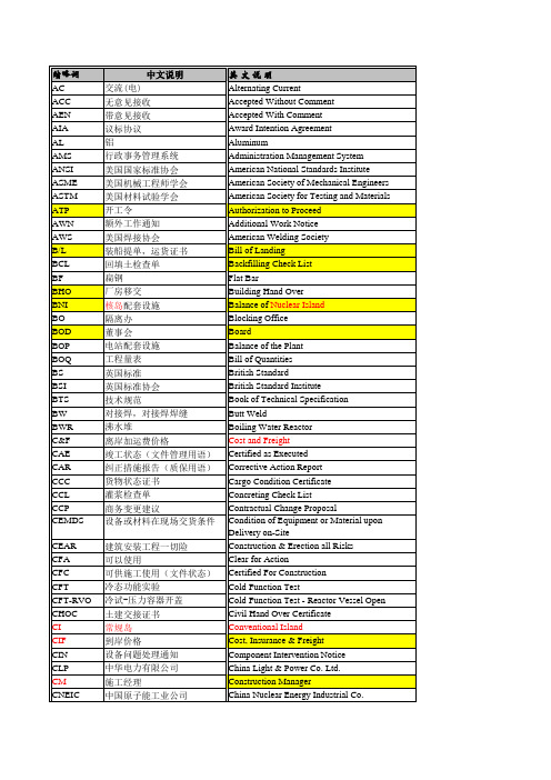
Execution Tracing File Final Acceptance Certificate Fast Breader Reactor For Construction Field Change Notice
FCO FCR FD FL FOB FP FPW FRA FS FSAR FSS FTG FU FW FW FW GAF GCR GCR GEC GEC/A GEPB GEPEC GGPC GMAW GN GNIC GNPGSC GNPJVC GNRB GQS GTAW GTC HFT HKSAR HO H-Point HPT HVAC IAEA IDD IEF II ISI ISO ISO ISO14000
CNNC
中国核工业总公司(中核总)
CO
商业运行
COD
商业运行日期
CP
建造许可证
CPL
符合性消缺单
CPT
临界前冷试
CQU
电厂质量放行
CRF
澄清问题申请单
CRI
临界
CRTC
中国汽车运输总公司
CS
碳钢
ห้องสมุดไป่ตู้
CTT
安全壳试验
CW
土建工程
CWJ
焊接接头目录
DCM
调试(日)例会
DCR
设计变更请求
DDD
国内直拨(电话)
International Standard Organization Iso
ITT JVC KAF Lab LANPC LBP L.C.E. LIC LOI LPT LT LIB LWGR MCR MF MH MIN MQ MQP MRF MSR MSS MSTM MT MTR NA NC NCC NCR NDE NDT NEPC NFC NFU NI NNSA NPS NPT NQR NRC NS NSSS NTR NUSS OA OAC OAW
AMM手册查询教材R1

AMM手册查询1AMM手册概述1.1 用途飞机维护手册(Aicraft Maintenance Manual,AMM)提供航线和定检维护时所需要的详细技术信息,包含系统及部件的工作描述、勤务、修理、更换、调节、检查的必需信息和正常在停机坪或维护机库完成飞机检查所需要的工具设备。
该手册可以用来满足维修人员工作和培训的需要。
1.2 手册有效性1.2.1客户化手册任何维修文件都有有效性(Effectivity),也就是此文件的适用性,即该维修文件是针对哪种机型制定的,对哪些飞机有效。
一般定义为:维修文件的有效性是指该文件是否适用于指定飞机及机载设备的依据。
维修文件对应飞机的有效性可以体现在以下4个方面:客户化(机型、机队有效性)、飞机型别号码(单架飞机的有效性)、型别特征(装备系统、APU、发动机的有效性)、时效性(手册改版的有效性)。
AMM手册为客户化的手册。
通过FSN(机队序列号)来确定有效性。
1.2.2飞机识别号一架飞机从设计、实验、成批的生产到投入运行,过程是非常复杂的,也是非常严谨的,每一个过程都会有一些代表该过程的编号,这些编号用以对机型进行识别,同时,也用来确定各类手册、服务通告、适航指令等的有效性。
在各手册前言都有飞机有效性对照表,以方便用户查询手册时了解手册有效性。
1.2.3空客飞机有效性对照表A.机队序列号(Fleet Serial Number,FSN) 航空公司机队的飞机按照顺序编号,如:001、002。
B.飞机构型(Version Rank) 如:G8E01 0010、G8E01 0011。
C.飞机型号(Model) 如:320-214。
D.厂家序列号(Manufacturer Serial Number,MSN) 某一机型持续生产的编号,如:0772、0799。
E.注册登记号(Registration)如:B-2360、B-2361。
1.2.4手册修订AMM手册修订分为:定期修订临时修订TR临时修订的内容包含在List of Effective Temporary Revisions(LETR)中,客户可以通过Airbus-World 和CD的形式获得最新的临时修订,在收到临时修订后应尽快将其上传至AirNav/Maintenance中。
火力发电厂常用英语词汇

火力发电站常用英语技术词汇boiler house: 锅炉房coal conveyor 输煤装置coal bunker: 煤仓coal mill磨煤机steam boiler, water boiler tube 蒸汽锅炉,管式锅炉furnace(combustion chamber): 炉膛( 燃烧室)water tube: 水管ash pit 灰坑superheater: 过热器water preheater: 水预热器air preheater: 空气预热器gas duct(flue): 烟气管, 烟道dust collecting plant: 集尘室electrical precipitation plant: 电气除尘室induced draught fan: 引风机chimney: 烟囱deaerator: 除氧器feed water tank: 供水箱boiler feed pump: 给水泵switchgear: 开关设备cable tunnel: 电缆通道cable cellar: 电缆槽turbine room: 汽轮机室steam turbine with alternator: 蒸汽汽轮发电机组economizer: 省煤器steam drum: 汽包surface condenser: 表面凝汽low-pressure preheater: 低压预热器circulating water pipe(pump): 循环水管control room: 控制室electrostatic dust remover(precipitator):静电除尘器pulverizer 磨煤机slag pump 灰渣泵thermal cycle: 热力循环(net)heat rate: (净)热耗率Assemblie: 集合,集结,组装comment 注释,评论module : 模块standby: 备用proximity 相近,接近,亲近detector: 探测器bracket: 支架interlocks 互锁,联锁axial: 轴向的surge conditions: 喘振:accessory: 附件pulsation: 有节奏的跳动,跳动fossil fired: 燃煤intent: 意图,目的,意向intend: 意指,想要,打算consistent: 一致的,调和的practice: 惯例,实习,实践intrinsic: 固有的,内在的procurement 获得,获取fabrication: 制作,构成,伪造物vent: 通风孔,出烟孔,出口,放出,排出,noncondensible gas: 不凝结气体intermittent 间歇的,断断续续的blowdown : 排污tank: 桶,箱,罐diagram: 图表deaerator: 除氧器corrosion : 侵蚀,腐蚀状态concentration 集中,集合,浓缩,浓度recommend 推荐,介绍,托付,劝告abnormal and normal conditions: 变工况和额定工况warm up: 暖机acid wash: 酸洗scale: 范围,水垢,水锈,比例,刻度sludge :: 污泥,淤泥foreign matter: 不相关的物质facilitate: 推动,促进,使简化multistage: 多级的remote control: 遥控safety relief valve: 安全卸压阀gauge: 量规,量表,测量manhole: 人孔,检修孔equivalent: 等价物,相等的forging:: 锻造seat: 部位,座socket welding: 管座焊接enthalpy: 焓estimate: 评价,评估,估价parameters 参数,参量nominal : 名义上的,额定的,标称的MS — Main Steam : 主蒸汽Cycle:: 循环Intercept: 截止Fetting: 附件Gage:: 规,表,压力计Taps: 接头test wells: 测点插孔stress-relieved: 应力消除thermometer: 恒温计steam purge system: 蒸汽吹扫系统centrifugal type pumps: 离心式泵friction losses: 磨擦损失solenoid: 螺线管modulat: 调整,调节criteria: 标准wrenches: 扳手pipe taps: 管接头.A List of Abbreviations and Symbols in English-ChineseA ::Ash Handling System: 除灰系统AH :Air Heater: 空气预热器AAh :Analyzer, Alarm High : 分析器,高值报警:: AIV :Air Intake Valve: 进气阀ALIGN Alignment: 校正ALKF :Airlock Feeder: 锁气器AP ::Ash Slurry Pump: 灰浆泵ATM :Atmosphere 大气AC ::Air Conditioner: 空气调节器AFT :Atmosphere Flash Tank: 大气扩容器AC :Alternating Current: 交流电ALM :Alarm:: 报警AMP :Ampere: 安培AX THR BRG :Axis Thrust Bearing: 轴向推力,轴承ATMZ :Atomizing: 雾化AUTO :Automation 自动AUX :Auxiliary: 辅助的BA :Bottom Ash 底灰BAH ::Bottom Ash Hopper: 底灰斗BLR ::Boiler: 锅炉BSD ::Boiler Shut Down: 停炉BUSH :Bushing: 衬套BYPS :Bypass:: 旁路BVD ::Boiler Vents and Drains:: 锅炉疏水放气BFP :Boiler Feedwater Pump ::锅炉给水泵BFPT:Boiler FeedwaterPump Turbine: 锅炉给水泵汽机BFW ::Boiler Feedwater: 锅炉给水BM :Boiler Master 锅炉主控BMCR:Boiler Maximum ContinuousRating: 锅炉最大连续出力BFBP::Boiler Feed Booster Pump: 锅炉给水增压泵BNR :Burner: 燃烧器BOP :Balance Of Plant: 电厂辅机设备BPC :Blade Pitch Control: 叶片节距控制BT :Boiler Tube: 炉管CH: Crusher House: 碎煤房COMB ::Combustion 燃烧COMP ::Compressed Air: 压缩空气CONV ::Conveyer: 输送机CPL :Control Pannel Local: 就地控制盘CPM :Control Pannel Main: 主控盘CRT :Cathode Ray Tube: 阴极射线管:CT Current Transformer: 变流器CYCL :Cyclone: 旋风分离器CAS :Casing:: 缸、壳CB Circuit Breaker: 断路器COMP :Complete: 完成CCCW :Closed Circulating Cooling Water: 闭式循环冷却水CCW :Cycle Cooling Water: 循环水CCWHF ::Closed Cooling Water Heater 闭式冷却水冷却器CCWP :Closed Cooling WaterPump: 闭式冷却水泵CS :Closed Cooling Water System 闭式冷却水系统CH Coal Handling 煤的装卸CHK VLV :Check Valve: 逆止阀CIRC: Circulation: 循环CLR Cooler: 冷却器CLOW :Cooling Water: 冷却水CMPR :Compressor: 压缩机CNTL :Control: 控制CNTLE :Controller:: 控制器COND :Condensate: 凝结水CONDTY :Conductivity: 导电率CP: Condensate Pump: 凝结泵CIR: Circuit: 回路COUPI :Coupling: 联轴器CP: Condensate Polisher: 除盐装置CS: Control Switch 控制开关CRSV :Cold Reheat Safety Valve: 再热器冷段安全阀CV: Control Valve : 控制阀CWP: Circulation Water Pump: 循环水泵DMPR: Damper : 挡板DP Difference Pressure: 差压DPIC: Differential Pressure IndicatingController压差指示控制器DPT:Differential Pressure Transmitter 压差变送器DRN: Drain: 疏水DV Drain Valve:: 疏水阀DC Direct Current: 直流电DSH: Desuperheater: 减温器DCA: Drain Cooler Approach: 疏水冷却器通道DEAER Deaerator: 除氧器DEV: Deviation: 偏差DIFFRLY: Differential Relay: 差动继电器DISCH VLV :Discharge Valve 排放阀DIST: Disturbance:: 故障、扰动DSCH: Discharge: 排出ECON: Economizer:: 省煤器EP Electrical Static Precipitator: 静电除尘器ECC Eccentricity :: 偏心EFF Efficiency: 效率EHC Electric Hydraulic Control: 电液控制EO Electric Operate: 电气操作EQ Equipment: 设备ER Error: 误差ES :Extraction System 抽气系统ESC Escape: 逃逸、超出ESS Engineering Safety System: 保安系统EU Engineering Unit : 工程单位EXH Exhaust: 排汽EXT Extract: 抽出FA :Fine Ash: 细灰FDR Feeder: 给料机FE :Flow Element:: 流量元件FI :Flow Indicator:: 流量指示件FDBK: Feedback: 反馈FITG Fitting: 连接件FLW Flow 流量FO :Fail Open: 故障时自动打开FT: Flow Totalizer: 流量累加器FT :Flow transmitter: 流量变送器FV :Flow Control Valve 流量控制阀FY :Flow Relay or Valve 流量传送器FA: Failure Alarm: 故障报警FD :Forced Draft : 强制通风FDF Forced Draft Fan: 送风机FIC :Flow Indicate Controller: 流量指示控制器FLT :Flash Tank : 扩容箱FLD :Field 磁场FLG :Flange: 法兰FLM Flame: 火焰FWH Feed Water Heater 给水加热器FO :Fuel Oil: 燃油FREQ Frequency: 频率FURN Furnace: 炉膛GLD Gland: 密封GRDR Grinder: 碎渣机GND Grounding: 接地GC :Generator Cooling: 发电机冷却GESE Gland Steam Condenser Exhauster:轴加风机GMT Generator MainTrandformer: 发电机变压器GRADGrandient: 梯度GS :Gland Steam: 轴封蒸汽GSC :Gland Steam Condenser: 轴封加热器GV :Governor Valve: 高压调门H ::Heat Conservation 保温HS: Hand Switch:: 手动开关HTR Heater: 加热器HV: Hand Control Valve: 手动控制器HY: Hand Relay or Transducer 手动继电器(转换器)H :Hand: 手动的HB :Heat Balance: 热平衡HD :Heater Drain:: 加热器疏水HDR :Header: 联箱HL ::Heat Loss: 热损失HMDY Humidity: 湿度HPH: High Pressure Heater: 高压加热器HPR :Hooper: 漏斗HPT :High Pressure Turbine: 高压汽机HR: Hot Reheat: 再热器热段HR: Heat Rate: 热耗率HSV: Hot Reheat Safety Valve: 再热器热段安全阀HV AC :Heating Ventilation& Air Conditioning:: 暖通HW :Hotwell: 热井HV ::Hand Control Valve: 手动控制器HYD :Hydraulic: 液力的INTLK :Interlock : 联锁IC :Instrument and Control:: 仪表与控制(热工)ICV ::Inrtermediate ControlValve 中压控制阀ID :Induced Draft 抽风,引风IDF ::Induced Draft Fan: 引风机IGN ::Ignition: 点火装置INLT :Inlet: 入口IPR ::Initial Pressure: 初压INST :Instrument: 仪表INVR :Inverter: 逆变器I /O:: Input/Output 输入/ 输出IP :Intermediate Pressure: 中压ISV ::Intermediate Pressure Turbine SteamValve: 中压缸进汽阀JP :Jet Pump: 喷射器LG :Level Gauge 液位计LVL ::Level: 水位,液位LA :Level Alarm: 液位报警LIM(LMIR): Limiter: 限制器LKG:: Leakage:: 泄漏LP :Low Pressure 低压L.P :Low Point : 低位LPH: Low Pressure Heater: 低压加热器LSH: Local Switch Hand: 就地开关LUB: Lubricating Oil: 润滑油M :Mechanical: 机械M :Motor: 马达MAG:: Magnetic: : 磁性MOD ::Mode: 方式:M/A :Manual/Automatic: 手动/ 自动MAN ::Manual :: 手动MARG: Margin:: 裕量MAX ::Maximum: 最大的,最大值的MCR ::Maximum Continuous Rating 最大连续出力MCV:: Main Control Valve: 主控制阀MD :Modulation Damper: 调节挡板MDBFP: Motor Driven Boiler Feedwater Pump: 电动给水泵MEAS ::Measure : 测量MFT: Master Fuel Trip: 主燃料跳闸MIN :Minimum: 最小的MKUP (MU) Make-up: 补充ML :Mill: 磨煤机MN :Main: 主要的M.O. :Manual Operation: 手操MPT :Main Power Transformer: 主变压器MS :Main Steam 主蒸汽MSV :Main Steam Valve: 主汽阀NOZ: Nozzle: 喷嘴NPSH :Net Pump Suction Head: 泵的静吸压头OL: Overload: 过载OLR :Overload Relay: 过载继电器OPER :Operation: 运行OSC :Oscillograph: 示波器OTLT: Outlet: 出口PA: Primary Air: 一次风PAF :Primary Air Fan: 一次风机PAH :Pressure Alarm High: 高压报警PAL :Pressure Alarm Low: 低压报警PB: Push Button 按钮PC :Power Centre: 动力中心PC: Pressure Controller: 压力控制器P.C. :Pressure Control: 压力控制PCP :Precipitator 除尘器PCV :Pressure Control Valve:: 压力控制阀PDI :Pressure Differential Indication:差压指示PDT :Pressure DifferentialTrandsmitter: 差压变送器PED :Pdestal::轴承座PERF CALC Performance Calculation:: 性能计算PF: Power Factor 功率因数PHTR: Preheater: 预热器PMP :Pump: 泵PNEU :Pneumatic: 气动的PR: Pressure Recorder: 压力记录计PRG :Purge: 吹扫PRV :Pressure Relief Valve: 泄压阀PRO :Protection: 保护PROGR:: Program: 程序PT: Pressure Transmitter: 压力变送器PULV: Pulverizer: 磨煤机PVSV :Pressure Vacuum Safety Valve 压力真空安全阀PW: Plant Water 厂用水PY: Pressure Relay: 压力继电器QA: Quality:: 质量,性能RB: Run Back: 快速降负荷RCV :Recovering: 回收RECIRC:: Recirculation 再循环RECT :Rectifier: 整流器RET :Return: 返回RH: Reheater: 再热器RO: Restriction Orifice: 节流孔板ROT :Rotor: 转子RTU :Remote Telemetry Unit:: 遥测装置SA :Secondary Air: 二次风SAT: Saturate: 饱和的SC :Steam Coil Air Heater:: 暖风器SCA V :Scavenge: 吹扫SD: Shut-off Damper: 关断挡板:Shut-Down 停机SEP :Separator 分离器SG: Switchgear 开关装置SH: Superheater: 过热器SLS :Seals:: 密封SO: Shut Off: 关闭SPD :Speed: 转速SPRA: Spray: 喷水SPT :Support: 支持:ST: Start: 启动,开始STD-BY :Stand By: 备用ST: System:: 系统STM :Steam: 蒸汽STR: Stator:: 定子STRNR: Strainer: 滤器SU: Start Up: 启动SV: Solenoid Valve: 电磁阀SUCT: Suction: 吸入SW: Switch: 开关:Steam Water: 汽水SBLWR: Soot Blower 吹灰器TBFP Turbine Drive Boiler Feedwater Pump 汽泵TCV :Temperature Control Valve 温度控制T.B.: Transfer Damper: 转换挡板TE: Temperature Element: 温度元件TG: Turbine-generator: 汽轮发电机Turbine-gear: Turbine-gear: 汽机盘车THERM :Thermal 热力的TMS: Turbine Master System: 汽机主控系统TRANS :Transfer: 转换TRBL: Trouble: 故障TRKG: Tracking: 跟踪TT: Temperature Transmitter: 温度变送器TTD: Terminal Temperature Difference:温度端差TW: Thermowell: 热电偶套管UAM :Unit Automatic Master: 机组自动系统V AC: Vacuum: 真空V AL: Value: 数值VB: Vibration 振动VLV: Valve: 阀门WH: Watthour 瓦小时WP: Working Point: 工作点WW: Water Wall 水冷壁WX: Watt Transducer: 功率转换器COVER :Crossover 切换管CV: Control Valve: 控制阀英汉对照表A/H :AUTOMATION/HAND : 自动/手动;A/M :AUTOMATION/MANUAL: 自动/ 手动;ALARM 报警;AUX :AUXILIARY :: 辅助;BYPASS 旁路CLOSE 关(状态,常指阀门);CODE: 代码;编码COLD START — UP: 冷态启动COMPUTER : 计算机CURVE ,LINE: 曲线,线DATA: 数据;文件;资料DECREAS : 减少DESK: 台,桌DIGIT: 数字DISK: 磁盘DYNAMIC ;DYNAMICAL: 动态F :FLOW 流量;FAST: 快FIGURE: 图示HIGH: 高HOT START — UP: 热态启动I&C :INSTRUMENT AND CONTROL 仪表与控制INCREAS: 增加INDICATION ;DISPLAY : 指示;显示;INLET 入口;INPUT 输入; INTERMEDIATE 中KEYBOARD: 键盘KW :KILOWATT 千瓦L :LOAD 负荷,负载;LOC :LOCAL : 就地LOW: 低MCS :MANAGMENT COMMANDSYSTEM 管理命令系统MODE : 方式,模式MW :MEGAWATT 兆瓦NORMAL: 正常OFF : 关(状态);ON : 开(状态);OPEN: 开( 状态,常指阀门);OPERATE : 运行;操作;OUTLET 出口;OUTPUT 输出;P :PRESSURE: 压力;PANEL 盘PARAMETER : 参数PIPE ;TUBE: 管道,管子PLANT: 厂,站POWER: 功率,电源;PRINT: 打印R :RATE : 比率,速率;R :RESISTANCE: 电阻;REM :REMOTE : 摇控;RESET 复位ROOM : 室RPM:: 转/ 分;S :SPEED 速度;SELECT 选择SET POINT 设定点SHUTDOWN : 停机;SIDE (某)侧,边;SILENCER 消音器SLOW : 慢STAND BY: 备用;START : 启动;STARTUP : 起动;启动;STATIC 静态STATION 站STOP: 停止;SYMBOL 符号SYSTEM: 系统T :TEMPERATURE:: 温度; TEST: 试验;TRANSMITTIER;TRANSDUCER: 变送器;传感器TRIP 跳闸;TRIP ACKNOW: 跳闸确认UNA V AIL 不允许( 不能投用的)UNIT : 单元、机组V ALVE 阀门W ARM START — UP: 温态启动ZOOM: 摄像机镜头锅炉部分ACTUAL MEGAWATT: 有功AIR DRAFT SEQUENCE: : 风机程序控制(顺控)AIR HEATER A MOTER: 空预器马达AAIR HEATER LOC/REM SELECT: 空预器就地/ 遥控选择AIR HEATER MOTOR LEAD: 空预器马达选择AIR HTR A SEC AIR OUT TEM 空预器A 二次风出口温度AIR PREHEATER: 空预器AIR SVCE SUPPLY: 服务空气ALARM LIMITS: :: 报警限制ALL AIR HTRS RUNNING 各空预器运行ALL PULV GRP SHUTDOWN 所有磨组停运ASH — HOPPER: : 灰斗ATTEMPERATOR: : 减温器AUX .ST: SPLY FOR ATOMIZ 辅助蒸汽供雾化蒸汽BOIL MILL A BNR MET TEMP 炉A 磨组喷燃器金属温度BOIL MILL A GR1 WDBOX PR 炉A 磨组第一组风箱压力BOILER AIR REQUIRED 锅炉风量需求(>30% )BOILER EFFLUENT STORAGE: POOL 锅炉废水池BOILER FOLLOW MODE: 炉跟随方式BOILER MASTER: 锅炉主控器BOILER TRIP RESET: : 锅炉跳闸复位BOILER: 锅炉BURNNER: : 燃烧器CHIMNEY ;STACK:: : 烟囱CLEAN: 清扫COAL BANKER: :: 煤仓COAL FEEDER : 给煤机COMBUSTION : 燃烧CONVEYOR: 皮带机COORDINATE MODE 协调方式CRUSHER: 破碎机DECR/INCR PRESS AT FIX LOAD:: 固定负荷方式增减压力DOWM COMER:: 下降管DRAIN & VENT: 疏水和排气ECONOMIZER : 省煤器EITHER FAN RUNNING : 任一风机运行EITHER ID FAN RUNNING 任一吸风机运行ELECTROSTATIC PRECIPITATOR : 静电除尘器FD FAN A FLOW:: A 送风机流量FD FAN/ID FAN A CONT DAMPER A送/ 吸风机控制挡板FEED W ATER FLOW: 给水流量FEEDER LOCAL SELECT: 给煤机就地控制选择FEEDER REMOTE SELECT: 给煤机遥控选择FLUE GAS: 烟气FORCED DRAFT FAN : 送风机FUEL GAS ID FAN A OUTLET PRESS A吸风机出口压力FURNACE PRESS: 炉膛压力FURNACE: 炉膛GAS COAL: :: 烟煤HEADER : 联箱、母管IGNITOR: : 点火器,油枪INDUCED DRAFT FAN : 引风机INDUCED&FORCED DRAFTS: 吸送风机INITIATE: 启动、引燃、激发、触发ISOLATION: 隔离;绝缘LFO .DISCH .PRESS : 轻油出口压力LIGHT OIL SEL GRP 1: 第一组轻油枪选择LIGHT OIL: 轻油LUB OIL PUMP:: 润滑油泵MAIN STEAM STOP VLV: 主蒸汽截止阀MAIN STEAM TEMP/PRESSURE/FLOW 主汽温度/压力/ 流量MAINTAINED IGNITORSPULVERIZER A:磨煤机A油枪操作MANUAL LOAD SET/RATE:手动负荷设定/ 负荷率MANUAL MODE: 手动方式MANUAL THROTTEL PRESS SETPOINT:手动节流压力设定值MILL A GROUP MASTER : A 磨组主控器MILL A LOAD: A 磨组负荷MILL A OUT TEMP CONT DAMPER : A磨组出口温度控制挡板MIN MAX LOAD (LIMITS ): 最大最小负荷(限制)MMMC =MILLIMETERMERCURY ;MMH2O: 毫米汞柱;毫米水柱O 2 IN THE FUEL GAS 烟气含氧量OPEN/CLOSE SWING VLVS 摆阀开/ 关OPERATE MODE SELECT: 运行方式选择PENDANT: : 悬吊管PLATEN SPARY CONTROL VLVS SIDEA : 屏过减温水A 侧控制阀PLATEN SUPERHEATER: 屏过PRESSURE DIFFERENCE: 压差PRI AIR DUCT PRESS 一次风管压力PRI AIR FAN A CONT DAMPER: A 侧一次风机控制挡板PRI AIR FAN A OUTLET PRESS A 一次风机出口压力PRI AIR FLOW MILL A CONT DAMPER 磨组一次风控制挡板PRI/SEC AIR FLOW MILL A A 磨组一次/ 二次风流量PRIMARY AIR FAN: 一次风机PRIMARY AIR SEQUENCE: 一次风控制PULVERIZER : 磨煤机PULVERIZER EMERGENCE TRIP 磨煤机紧急跳闸PULVERIZER INERT MODE SELECT: 磨煤机惰性方式选择PULVERIZER NORMAL MODE SELECT: 磨煤机正常方式选择PULVERIZER SELECTION A :: 磨煤机A 选择PULVERIZER: M/A: SELECT 磨煤机手/ 自动选择PURGE 吹扫RH ;REHEATER: 再热器SAFETY V ALVE:: 安全阀SCANNER BLOWERS: 火检吹扫器SEAL AIR FAN PRESS: 密封风机压力SEAL AIR FAN:: : 密封风机SEC AIR DUCT PRESS: 二次风管压力SEC AIR FLOW MILL A CONTDAMPER A 磨组二次风流量控制挡板SEC SH OUT STEAM TEM 二级过热器出口蒸汽温度SEC SH SPARY CONT VLVS SIDE A二级过热器减温水A 侧控制阀SECONDARY SH INLET TEMP 二级过热器进口温度SECONDARY: AIR 二次风SH ;SUPERHEATER: : 过热器SH STEAM ELECTR VLV: 过热器电磁阀SH STEAM TEMP SET POINT:: 过热温度设定点SH/RH SPARY W ATER STOP VLVS:: 过热器/ 再热器减温水截止阀SH/RH SPRAY CONTROL VLVSSELECT 过热器/ 再热器减温水控制阀选择SLIDING PRESS MODE: 滑压运行方式SOOT BLOWER: 吹灰器SPARK 火花,点火花SPEED CHANGE (NOT) PERMISSIVE: 速度切换(不)允许SPRAY : 喷水STACKER RECLAIMER :: 堆取料机START IGNITOR GRP 1: 第一组油枪点火STEAM DRUM: : 汽包STEAM 蒸汽STONE COAL: 无烟煤STOP IGNITORS GRP 1: 第一组油枪停止STOP/START FEEDER 给煤机停止/ 启动STOP/START IGNITORS: 油枪停止/ 启动STOP/START MILL: 磨组停止/ 启动STOP/START PA FLOW: 一次风停止/ 启动STOP/START PULVERIZER 磨煤机停止/ 启动STOP/START SEQUENCEPULVERIZER A: 磨煤机 A 程序停止/ 启动THROTTLE PRESS:: 节流压力TRANSPORT AIR SEQUENCE 风量程序控制(顺控)TURB FIRST STAGE PRESS 汽机第一级( 调节级) 压力TURBINE FOLLOW MODE: 机跟随方式TURBINE MASTER: 汽机主控器TWIN FLOW AIR HTR A CONT VLV: :双流式空预器控制阀UNLOADER: :: 卸煤机WATER 水WATERW ALL: : 水冷壁汽机部分:EMERG OIL PUMP: 事故油泵<P>CICR PMP DISCHARGE VLV: 循环泵出口阀1ST STAGE PRESS: 第一级压力ACTUAL MEGA WATT: : 实际负荷数AMS :ADMISSION: MODESELECTION 进汽方式选择AUX STEAM HEADER: : 辅汽联箱AUX STEAM TEMP CONTROL: 辅汽温度控制AUX STM HEADER PRESS CONTROL VLV 辅汽联箱压力控制阀BALANCE: : 平衡BEARING BRASS:: 轴瓦BEARING: : 轴承BLADE 叶片BOILER FOLLOW MODE: 锅炉跟随方式BOOSTER FEED PUMP: 前置给水泵CICR WTR PUMP: 循环泵CIRCULATING PUMP: : 循环泵CIRCULATING: 循环CLOSED COOLING W ATER: 闭式冷却水CLOSED COOLING WTR PUMP: 闭式冷却水泵CMPTR: : 计数器CONDENSATE PUMP: 凝泵CONDENSER AIR SUCTION VLV: 凝汽器抽空气阀CONDENSER HOT WELL: : 热井CONDENSER LEVEL CONTROL VLV:凝汽器水位控制阀CONDENSER: 凝汽器CONDS EXTR PUMP DISCH : 凝结水抽吸泵出口CONDS STOR TANK LEVEL: 凝结水储水箱水位COOLER: : 冷却器COOLNG WTR PUMP: 水冷泵COORDINATE MODE: : 协调方式CV :CONTROL V ALVE 高压调门CYLINDER 、CASING: 汽缸DEAERATOR LEVEL CONTROL VLV:除氧器水位控制阀DEAERATOR: : 除氧器DECR PRESS AT FIX LOAD: 在负荷不变下减压DEMI WATER: 除盐水DISPATCH PARTICIPATION 调度(参与)指令DURM PRESSURE:: 汽包压力EJECTOR: 喷射器,抽气器EMERGENCY GOVERNOR 危急保安器EXHAUST: 排汽EXPANSION: 膨胀EXTR ST TO HP HTR 抽汽至高加EXTRACTION STEAM 抽汽FILTER: : 滤网FLANGE 法兰FUNCTION GROUP: 功能组FW CONTROL V ALVE ' S BYPASS VLV: 给水控制阀的旁路阀FW FLOW 30% CONTROL VLV : 30% 给水控制阀FW FLOW MASTER CONTROL: 给水流量主控FW HP HTR DISCH TEMP: 给水高加出口温度FW PUMP RECIRCUL CONTROL VLV 给水泵循环控制阀FW VLV: 给水阀门GEARING: 盘车GOVERNOR: 调速器HP ATTEM PRESS CONTROL VLV: 高旁减温水压力控制阀HP ATTEMP BLOCK VLV: 高旁减温水闭锁阀HP BYPASS &HP ATTEMP VLVS:高压旁路及减温水阀HP BYPASS PRESS CONTROL VLV 高旁压力控制阀HP BYPASS PRESS SET POINT: 高旁压力设定值HP BYPASS TEMP CONTROL V ALVE高旁温度控制阀HP&LP BYPASS COMMAND 高压及低压旁路指令HPH :HIGH PRESSURE HEATER : 高加HYDRAULIC OIL STATION PUMP: 液压油站泵INCR PRESS AT FIX LOAD: 在负荷不变下增压INT POS: 中间状态IV :INTERMEDIATE V ALVE 中压联合汽门JACKING OIL PUMP 顶轴油泵LP HTR STOP VLV 低加截止阀LP &HP BYPASS PRESS SIDE A 低压或高压旁路A侧压力LP &HP BYPASS TEMP SIDE A 低压或高压旁路A侧温度LPH :LOW PRESSURE HEATER:低加LUBE OIL PUMP: 润滑油泵MAKE -UP W ATER: 补给水MANUAL LOAD RATE 手动负荷率MANUAL LOAD SET 手动负荷设定MANUAL Throttle Press Set Point手动节流压力设定值MEASURE SELECTION 测量选择站MOP :MAIN OIL PUMP: 主油泵MOTOR DRIVEN FEED WATER PUMP 电动给水泵MSV :MAIN STOP V ALVE: 主汽阀NOZZLE 喷嘴OIL PURIFIER: 净油器OIL STORAGE TANK : 储油箱OPERATE MANUAL MODE: 手动方式OPERATE MODE SELECT: 运行方式选择PILOT V ALVE: 错油门PLATEN SH INLET TEMP SIDE A: A侧屏过入口温度PRIMARY SH STOP V ALVE: 一级过热器截止阀PUMP A DISCH PRESS : A 泵出口压力RH SPRAY BLOCK VLVSTRIP INIT 再热器喷水闭锁阀跳闸启动RH SPRAY WTR STOP VLVS: 再热器喷水截止阀RH STEAM ATTEM FLOW: 再热喷水流量RH STEAM TEMP OUTLET: 再热器出口温度ROTOR 转子SEAL: 密封SHAFT 轴SILENCER: 消音器SLIDING PRESS MODE: 滑压方式SPEED INDICATOR OR SPEEDMETER: : 转速表STATOR 定子STEAM TURBINE : 汽轮机ST -UP BOIL FDW PUMP: 启动给水泵SUCTION PUMP: 抽吸泵SURGE APPROACH: 喘振SYNCHRONIZER: 同步器TFW PMP DISCHARGE VLV: 汽动泵出口阀TFW PUMP MAIN OIL PMP: 汽动给水泵的主油泵THROTTLE ORIFICE 节流孔板TURBINE DRIVEN FEED WATER PUMP: 汽动给水泵TURBINE FW PUMP AUX &VLV 小机给水泵辅汽及阀门TURBINE GENERATOR: 汽轮发电机组TURBINE INLET PRESS: 汽机入口压力TURBINE MASTER : 汽机主控器TURBING FOLLOW MODE: 汽机跟随方式V ACCUM 真空V ACUUM BROKEN V ALVE: 真空破坏门V ACUUM SEQ : 真空程控VIBRATION: 振动电液调节及控制部分1STAGE PRESSURE FEEDBACK: 第一级压力反馈ABNORMAL CONDITION: 异常状态ACCELERATION: 加速度ACTIVE POWER:: 有功功率ADMISSION MODE: 进汽方式ADS(ALARM DISPLAY SELECTPANELS) 报警显示选择屏AERIAL LINE: 架空线ALTERNATING CURRENT (AC): 交流AMPERE: 安培ANGLE OF LAG: 滞后角ANGLE OF LEAD: 超前角ANODE: 阳极ARC: 电弧ARMATURE 电枢AST :AUTO SHUT-DOWN TRIP: 自动停机遮断ASYNCHRONOUS MOTOR: 异步电动机AT SET SPEED: 在设定速度位置ATC :AUTO TURBINE CONTROL:自动汽轮机控制AUTOFORMER: 自藕变AUTORECLOSING : 自动重合闸AUXI TRANSFORMER : 厂用变BACK UP TRANSFORMER 备用变BACK-UP OVERSPEED TRIP TEST 备用超速跳闸试验ELECTRICAL TRIPTEST 电气跳闸试验BACK-UP SPDSIG LOST: : 后备速度信号失去BARRING OIL PUMP 盘车油泵BASE LOAD: 基荷BATTERY : 电池BATTERY BACKED CLOCK 电池备用时钟BDV :BLOWDOWN VLV: 泄放阀BOOSTER PUMP: 前置泵BULB : : 灯泡BUS SECTION : 母线分段BUS: 母线BUSBAR FRAME: 母线架BUSCOUPLER: 母联BUSHING 套管CABLE 电缆CAPACITANCE: 电容CARRIER 载波CATHODE : 阴极CCR: 中控室CHARGING EQUIPMENT : 充电设备CHEST /ROTOR WARMING: 腔室/转子预暖CIU : 计算机接口单元CLOSE : 合闸CLOSED V ALVES OVERSPEED TEST关闭阀超速CLOSED-LOOP : 闭环COIL:: 线圈COMBINED RECLOSING 综合重合闸COMBINED REHEAT V ALVES: 中压联合阀COMMON SERVICES LOGIC SUITE::公用系统逻辑柜COMMUNICATION: 通讯CONDUCTOR : 导体CONFIGURATION: 结构,布置,外形:CONTROL OIL: 控制油CORE: 铁芯CPU(CENTARL PROCESSING UNIT:中心处理单元CRT: 显示屏CURRENT TRANSFORMER: 电流互感器CURRENT 电流CV:: 控制阀DAS: 数据采集系统DECREASING LOAD RATE: : 减负荷率DIESEL GENERATOR : 柴油发电机DIRECT CURRENT (DC) 直流DISCONNECTOR : 隔离开关DISTRIBUTED CONTROL SYSTEM: 分散控制系统E.W.S.: 工程师工作站EHC STATUS: 电液调节系统状态EHC :ELECTRO-HYDRA CONTROL SYSTEM: 电液调节控制系统EHV MIMIC PANEL : 电气高压模拟屏ELECTRICAL MALFUNCTION SYSTEM FAULT : 电气失灵系统故障EMERGENCY OIL PUMP: 事故油泵EMERGENCY SEAL OIL PUMP: 事故密封油泵ETS :EMERGENCY TRIP SYSTEM:危急跳闸系统EXCEPTION REPORT: 例外报告EXCITE 励磁EXCITOR 励磁机FA/PA POSITION : 全周/ 部分(进汽)位置FAST-ACTING SOLENOID: 快动电磁阀FIRST STAGE PRESS 调节级压力FIS :: 流量显示开关FREQUENCY: 频率FRF :FIRE RESISTANT FLUID:: 抗燃油FULL ARC : 全周进汽GAS : 瓦斯GEN. SHAFT SEAL&STATORWIND : 发电机密封及静子绕组GENERATOR : 发电机GROUNDING(EARTHING) 接地H2 TEMP CONT V : 氢气温度控制阀HARDW ARE 硬件HOLD: 保持HYDRAULIC FLUID PRESS: 抗燃油压力I.C.S: 数字控制站终端模件IN STANDBY: 在备用状态IND: :: 指示器INDUCTANCE: 电感INHIBITED: 停止进行、禁止INSULATOR 绝缘子INTERCEPT V ALVE: 中间截流阀INTERCEPT V ALVES: 中间截止阀INTERFACE 接口KILOW ATT 千瓦LC: 液位控制器LI: 液位显示LIGHT: 照明LINE 线路LK: 液位控制站LOAD DECREASING ;AT SET LOAD 负荷减;在设定负荷LOAD FLOW : 负荷潮流分布LOAD INCREASING: 负荷增LOAD LIMITING SET: 负荷极限设定LOAD MONITORING: 负荷监视LOAD SELECT: :: 负荷选择LOAD SET: 负荷设定LOAD: 负荷LOADING RATE LIMIT : 负荷(增、减)率限定LOCKED OUT: 闭锁LOSS : 损耗LOSS OF PWR:: 失去电源LVDT :线性位移差动变送器MAGNETIC FIELD: 磁场MAIN OIL PUMP: 主油泵MAIN SEAL OIL PMP : 主密封油泵MAIN STEAM PRESS 主蒸汽压力MAIN TRANSFORMER STEP-UPTRANSFORMER: 主变MANUAL: 手动MCC: 马达控制中心MEGAWATT: 兆瓦MFP : 多功能控制器MOTOR: 电动机MSPL :MAIN STEAM PRESSURELIMITER : 主汽压力限制器MSV: 主蒸汽阀NEUTRAL POINT: 中性点OHM: 欧姆OIL GAUGE: 油位表OPC :OVERSPEED PROTECTIONCONTROL: 超速保护控制OPEN-LOOP : 开环OPER AUTO: 操作员自动::OPERATING MODE : 操作方式ORP :OIL RESET PISTON: 油复位活塞ORSV :OIL RESET SOLENOID VLV 油复位电磁阀OTSV :OIL TRIP SOLENOID VLV: 油跳闸电磁阀OVER CURRENT: 过流OVER VOLTAGE : 过压OVERLOAD: 过载PART ARC : 部分进汽PC: 动力中心PDIS : 压差显示开关PEAK LOAD: 峰荷PERMANENT MAGNETIC GENERATORDF 永磁发电机PG: 压力计PHASE ANGLE : 相角PHASE: 相PIC: 压力显示控制器PK: 压力控制站PLUG : 插头PLUG SOCKET: 插座POLE:: 电极POTENTIAL TRANSFORMER 电压互感器POWER 功率POWER FACTOR: 功率因数POWER LOAD UNBALANCE: 功载不平衡PP :: PREESSURE POINT 压力检测点PRI SPD SIG LOST 一次速度信号失去PS: 压力开关PT: 压力变送器REACTANCE: 电抗REACTIVE POWER: 无功功率RECLOSING : 重合闸REHEAT PRESS:: 再热汽压力REMOTE AUTO: 远方自动REMOTE OPERATION : 远操RESISTANCE: 电阻RSM :ROTOR STRESSMONITORING: 转子热应力监视:RSV: 再热汽截止阀SAFELY OIL : 安全油SCR CONTROLLER: 可控硅整流控制器SEAL OIL: 密封油SHUT-OFF V ALVE:: 切断阀SIGNAL: 信号。
AMS Series 表面挂载扬声器操作手册说明书

Surface mountloudspeakersOperation Manual2 AMS Series Operation Manual rev 1.0.0Table of Contents Table of Contents1. Introduction2. Safety Notices3. Unpacking4. Accessories5. Installation5.1. Installation using included yoke bracket (6)5.2. Installation using optional VariBall bracket (7)6. Setting transformer taps7. Product Dimensions8. Technical Specifications9. WarrantyAMS Series Operation Manual rev 1.0.031. Introduction1. IntroductionThank you for purchasing this new AMS Series product. Designed for both speech and music program material, the T annoy AMS range provides exceptional sonic quality and long-term reliability in all surface mount applications.The AMS range offers five models: three featuring a new generation of Dual Concentric™ drivers and two with an improved version of T annoy’s ICT™ technology. All new drivers have 16 ohm nominal impedance for optimizeduse with Lab.gruppen amplifiers. Other features include IP 64 rating for outdoor use, high-temperature moldedcabinets and custom color options. All AMS loudspeakers include a built-in line transformer.Because all AMS models are true point-source loudspeakers, they may be mounted horizontally or verticallywithout affecting performance. All models include a standard mounting yoke; a multi-angle accessory bracket is available as an option.2. Safety NoticesInstallation Safety Notice1. The user is responsible for fixing the hardware to the surface to ensure safe operation. The fixings mustsupport the weight of the product. Please consult the manual’s specification page for the appropriateweights. Please consult the relevant construction codes in your region for further information on suitablehardware fixing methods.2. Some regional construction codes require the use of a secondary method of securing loudspeakers tosurfaces to provide security of a back-up support. A secondary support line should be attached from thesafety loop on the rear of the product to a source point on the wall. Please consult the relevant constructioncodes in your region.3. Tannoy will not be held accountable for any damage caused by incorrect installation.Electrical Safety NoticeTo comply with the standard UL1480, metal-clad flexible conduit (BX) is required for connection to the terminal block for proper earth grounding.SAFETY NOTE: In order to comply with the relevant fire safety regulations (i.e. BS 5839:1998), it is requiredthat in the event of fire, that failure of the circuit to which the loudspeaker is connected does not occur before evacuation of the building is complete. Suitable measures include:• Use of terminal blocks (for connection to primary) with a melting point of not less than 650°C, for example constructed from ceramic materials;• Use of terminal blocks of a lower melting point but protected with thermal insulation;• Use of terminal blocks such that, on melting, an open-circuit or a short-circuit does not occur.4 AMS Series Operation Manual rev 1.0.03. UnpackingAMS Series Operation Manual rev 1.0.053. UnpackingEvery Tannoy product is carefully inspected before shipment. After unpacking, please inspect your product to ensure no damage has occurred in transit. In the unlikely event of damage, please notify your dealer and retain all shipping materials as your dealer may require return shipment.4. AccessoriesOptional multi-angle accessory bracketAMS 5 Multi-Angle Bracket AMS 6 & 8 Multi-Angle Bracket The optional multi-angle accessory bracket utilizes a ball-in-socket design to enable free orientation of the loudspeaker at any angle on either the horizontal or vertical axis. If desired, the loudspeaker orientation can beeasily changed within minutes. For installation instructions, see section 5.2.5. Installation6 AMS Series Operation Manual rev 1.0.05. Installation5.1. Installation using included yoke bracket1. Fix the yoke bracket to an appropriate structural surface using a suitable fixing method.2. Remove the yoke trims from the product to access the bracket fixing points.3. Set the transformer tap as detailed in Section 6 following.4. For indoor installation (proceed to step 5 for outdoor installation): Connect the euro-style plug to the wires, observing correct polarity. Use pins 1(+) and 2 (-) for connection of the loudspeaker. Use pins 3 (-) and 4 (+) for connection of additional loudspeakers in a distributed line. NOTE: Tighten pins 3 and 4 even if not used to prevent vibration of the screws.5. For outdoor installation: Feed the loudspeaker wire(s) through the opening in the neck of the cable entry cover included with the product.Connect the euro-style plug to the wires, observing correct polarity. Use pins 1(+) and 2 (-) for connection of the loudspeaker. Use pins 3 (-) and 4 (+) for connection of additional loudspeakers in a distributed line.NOTE: Tighten pins 3 and 4 even if not used to prevent vibration of the screws.6.Place the loudspeaker inside the yoke bracket. Position buffers between bracket and loudspeaker as shown. Attach with supplied fixings using a 5mm Allen key. Use the longer hex screws supplied when mounting the yoke bracket.5. InstallationAMS Series Operation Manual rev 1.0.077. Connect the euro plug to the loudspeaker. For outdoor installation, attach the cable entry cover using a 3 mm Allen key and the included screws. Orient the cover plate so that the neck opening is facing downward to minimise entry of moisture or particulates.8. Connect a secondary support line to the safety tab at the rear of the cabinet.5.2. Installation using optional VariBall bracketPlease see AMS VariBall Accessory Backet - Mounting and Installation Guide for reference.1. Fix the wall bracket to the wall surface using suitable fixing method for supporting the loudspeaker with ample safety margins.2. Fix the ball bracket to the rear of the loudspeaker using the supplied screws and a 3 mm Allen key. Two screws are used for AMS 5 models; four screws are used for AMS 6 and AMS 8 models.3. Set the transformer tap as detailed in Section 6 following.4. For indoor installation (proceed to step 5 for outdoor installation): Connect the euro-style plug to the wires, observing correct polarity. Use pins 1(+) and 2 (-) for connection of the loudspeaker. Use pins 3 (-) and 4 (+)for connection of additional loudspeakers in a distributed line. Note: Tighten pins 3 and 4 even if not used to prevent vibration of the screws.5. For outdoor installation: Feed the loudspeaker wire(s) through the opening in the neck of the cable entry cover included with the product.5. Installation8 AMS Series Operation Manual rev 1.0.0Connect the euro-style plug to the wires, observing correct polarity. Use pins 1(+) and 2 (-) for connection of the loudspeaker. Use pins 3 (-) and 4 (+) for connection of additional loudspeakers in a distributed line.NOTE: Tighten pins 3 and 4 even if not used to prevent vibration of the screws.6. Raise the lever to open the wall bracket. Insert the ball bracket into the wall bracket, position as required, and then lower the lever to lock the ball bracket into place. Raise the lever if any readjustment is necessary. Once in final position, tighten the grub screw at the bottom of the wall bracket to secure in place.7. Connect the euro plug to the loudspeaker. For outdoor installation, attach the cable entry cover using a3 mm Allen key and included screws. Orient the cover plate so that the neck opening is facing downward to minimise entry of moisture or particulates.8. Connect a secondary support line to the safety tab at the rear of the cabinet.5. InstallationAMS Series Operation Manual rev 1.0.09AMS 5 - Variball Angle Options (Vertical)18°AMS 5 - Variball Angle Options (Horizontal)5. Installation10 AMS Series Operation Manual rev 1.0.0AMS 6 - Variball Angle Options (Vertical)63°AMS 6 - Variball Angle Options (Horizontal)45°5. Installation AMS 8 - Variball Angle Options (Vertical)AMS 8 - Variball Angle Options (Horizontal)45°6. Setting transformer taps6. Setting transformer taps1. The rotary transformer tapping switch is located directly above the wiring connector.CAUTION: The loudspeaker is supplied with the tap switch set in low impedance mode. Never connect theloudspeaker to a 70/100 V amplifier output while switched to low impedance mode.2. Set the rotary switch to the appropriate position for low impedance operation or for use in 70/100 Vdistributed systems.Models with 5-inch drivers are fitted with 30 W transformers. In distributed line applications, the transformer can be tapped at 30 W, 15 W and 7.5 W, with an additional 3.75 W tap for 70 V line systems.Models with 6-inch and 8-inch drivers are fitted with 60W transformers. In distributed line applications, thetransformer can be tapped at 60 W, 30 W and 15 W, with an additional 7.5 W tap for 70 V line systems.7. Product Dimensions7. Product DimensionsAMS 5DCØ11.0Ø22.0AMS 5ICTØ11.0Ø22.07. Product DimensionsAMS 5ICT LSØ11.0Ø22.0AMS 6DCØ22.0Ø11.090.07. Product Dimensions AMS 6ICTØ22.0Ø11.090.0AMS 6ICT LSØ22.0Ø11.090.07. Product DimensionsAMS 8DC90.0Ø22.0Ø11.0CABLE ENTRY COVER FOR EXTERNAL USE.8. Technical Specifications 8. Technical SpecificationsAMS 5DC ModelPart Number Colour8001 7945 Black8001 7946 WhiteNotes:1. Average over stated bandwidth. Measured inan IEC baffle in an Anechoic Chamber2. Unweighted pink noise input, measured at1 metre on axis3. Long term power handling capacity as definedin EIA - 426B testA full range of measurements, performancedata, CLF and Ease™ Data for AMS 5DC can bedownloaded from .Tannoy operates a policy of continuous researchand development. The introduction of new materialsor manufacturing methods will always equal orexceed the publishing specifications, which Tannoyreserves the right to alter without prior notice. Pleaseverify the latest specifications when dealing withcritical applications.Copyright (c) 2015 Tannoy Limited. All rights reserved.8. Technical SpecificationsAMS 5ICT ModelPart Number Colour8001 7955 Black8001 7956 WhiteNotes:1. Average over stated bandwidth. Measured inan IEC baffle in an Anechoic Chamber2. Unweighted pink noise input, measured at1 metre on axis3. Long term power handling capacity as definedin EIA - 426B testA full range of measurements, performancedata, CLF and Ease™ Data for AMS 5ICT can bedownloaded from .Tannoy operates a policy of continuous researchand development. The introduction of new materialsor manufacturing methods will always equal orexceed the publishing specifications, which Tannoyreserves the right to alter without prior notice. Pleaseverify the latest specifications when dealing withcritical applications.Copyright (c) 2015 Tannoy Limited. All rights reserved.8. Technical Specifications AMS 5ICT LS ModelPart Number Colour8001 7965 Black8001 7966 WhiteNotes:1. Average over stated bandwidth. Measured inan IEC baffle in an Anechoic Chamber2. Unweighted pink noise input, measured at1 metre on axis3. Long term power handling capacity as definedin EIA - 426B testA full range of measurements, performance data,CLF and Ease™ Data for AMS 5ICT LS can bedownloaded from .Tannoy operates a policy of continuous researchand development. The introduction of new materialsor manufacturing methods will always equal orexceed the publishing specifications, which Tannoyreserves the right to alter without prior notice. Pleaseverify the latest specifications when dealing withcritical applications.Copyright (c) 2015 Tannoy Limited. All rights reserved.8. Technical SpecificationsAMS 6DC ModelPart Number Colour8001 7970 Black8001 7971 WhiteNotes:1. Average over stated bandwidth. Measured inan IEC baffle in an Anechoic Chamber2. Unweighted pink noise input, measured at1 metre on axis3. Long term power handling capacity as definedin EIA - 426B testA full range of measurements, performancedata, CLF and Ease™ Data for AMS 6DC can bedownloaded from .Tannoy operates a policy of continuous researchand development. The introduction of new materialsor manufacturing methods will always equal orexceed the publishing specifications, which Tannoyreserves the right to alter without prior notice. Pleaseverify the latest specifications when dealing withcritical applications.Copyright (c) 2015 Tannoy Limited. All rights reserved.8. Technical SpecificationsAMS Series Operation Manual rev 1.0.021AMS 6ICT ModelNotes:1. Average over stated bandwidth. Measured in an IEC baffle in an Anechoic Chamber 2. Unweighted pink noise input, measured at 1 metre on axis3. Long term power handling capacity as definedin EIA - 426B testA full range of measurements, performance data, CLF and Ease™ Data for AMS 6ICT can be downloaded from .Tannoy operates a policy of continuous research and development. The introduction of new materials or manufacturing methods will always equal or exceed the publishing specifications, which Tannoy reserves the right to alter without prior notice. Please verify the latest specifications when dealing with critical applications.Copyright (c) 2015 Tannoy Limited. All rights reserved.8. Technical Specifications22AMS Series Operation Manual rev 1.0.0AMS 6ICT LS ModelOrdering InformationPart Number Colour 8001 8340 Black 8001 8341WhiteNotes:1. Average over stated bandwidth. Measured in an IEC baffle in an Anechoic Chamber 2. Unweighted pink noise input, measured at 1 metre on axis3. Long term power handling capacity as definedin EIA - 426B testA full range of measurements, performance data, CLF and Ease™ Data for AMS 6ICT LS can be downloaded from . Tannoy operates a policy of continuous research and development. The introduction of new materials or manufacturing methods will always equal or exceed the publishing specifications, which Tannoy reserves the right to alter without prior notice. Please verify the latest specifications when dealing with critical applications.Copyright (c) 2015 Tannoy Limited. All rights reserved.8. Technical SpecificationsAMS Series Operation Manual rev 1.0.023AMS 8DC ModelOrdering InformationPart Number Colour 8001 7990 Black 8001 7791WhiteNotes:1. Average over stated bandwidth. Measured in an IEC baffle in an Anechoic Chamber 2. Unweighted pink noise input, measured at 1 metre on axis3. Long term power handling capacity as definedin EIA - 426B testA full range of measurements, performance data, CLF and Ease™ Data for AMS 8DC can be downloaded from .Tannoy operates a policy of continuous research and development. The introduction of new materials or manufacturing methods will always equal or exceed the publishing specifications, which Tannoy reserves the right to alter without prior notice. Please verify the latest specifications when dealing with critical applications.Copyright (c) 2015 Tannoy Limited. All rights reserved.9. Warranty9. WarrantyNo maintenance of the AMS Series loudspeaker is necessary.All Tannoy products have been produced and tested with care to assure reliable service.All passive components are guaranteed for a period of five years from the date of purchase from an authorised Tannoy dealer, subject to the absence or evidence of misuse, overload, or accidental damage.All active and electronic components are guaranteed for a period of one year from the date of purchase from an authorised Tannoy dealer subject to the absence of, or evidence of, misuse, overload or accidental damage.If at any time during this warranty period the equipment proves to be defective for any reason other thanaccident, misuse, neglect, unauthorised modification or fair wear and tear, we will repair any such manufacturing defect or, at our option, replace it without charge for labour, parts or return carriage. If you suspect a problem with a Tannoy product then, in the first instance, discuss it with your Tannoy dealer. If you require furtherassistance then we ask that you deal directly with your local Tannoy distributor. If you cannot locate yourdistributor please contact Customer Services, Tannoy Ltd at the address given below.Customer ServicesTannoy Ltd.Rosehall Industrial EstateCoatbridgeStrathclydeML5 4TFScotlandTel: 01236 420199 (National)+44 1236 420199 (International)Fax: 01236 428230 (National)+44 1236 428230 (International)Support: DO NOT SHIP ANY PRODUCT TO TANNOY WITHOUT PREVIOUS AUTHORISATIONOur policy commits us to incorporating improvements to our products through continuous research anddevelopment. Please confirm current specifications for critical applications with your supplier.24 AMS Series Operation Manual rev 1.0.0Notes NotesAMS Series Operation Manual rev 1.0.025NotesNotes26 AMS Series Operation Manual rev 1.0.0Notes NotesAMS Series Operation Manual rev 1.0.02751119/171846Tannoy operates a policy of continuous research and development. The introduction of new materials or manufacturing methods will always equal or exceed the published specifications. All specifications are subject to change without notice.Copyright (c) 2015 Tannoy Limited. All rights reserved.。
AMS所有规范定期测试项目汇总

不适用
每月
不适用
多孔性–每批
焊接能力-规定时每月
每周
每周
AMS - 2422
镀金
每批
每月
每月
每月
不适用
焊接能力–每批
每周
每周
AMS - 2423
硬块沉淀-镍板
每月
不适用
不适用
不适用
不适用
硬度–每批
应力–每季度
每周
每周
定期测试-续
规范
描述
粘结剂
耐腐蚀
成分
脆化
耐磨
损性
其它规定的测试
电镀
溶液
清洗剂
AMS - 2424
转换涂装钛
每批
不适用
不适用
不适用
不适用
水点–每批
每周
每周
AMS - 2488
阳极电镀-钛
不适用
不适用
不适用
不适用
每月
Prop.相容性–每月
每周
每周
AMS - 2700
耐腐蚀钢钝化
不适用
每批
不适用
不适用
不适用
每周
每周
.
镍板-
低应力
每批
铁基-每月
不适用
每月
不适用
应力–每季度
耐热性.-每月
硬度–每月
每周
每周
AMS - 2433
镍-铊-硼/镍-硼
无电镀板
每批
每月
每月
每月
每月
硬度–每月
焊接能力-规定时每批
每天
每周
AMS - 2434
锡–锌合金
每批
每月
每月
AMS(说明书) Proposal for shidongkou_Chinese
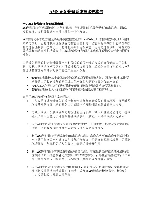
4.利用AMS智能设备管理系统的在线组态功能,维修人员可在维修车间或中控室(甚至在办公室)进行智能设备组态修改,无需查询回路接线图,无需到现场查线,从而避免了人为失误,提高了维修安全性;
5.利用AMS智能设备管理系统的先进诊断功能,可在线诊断智能仪表电路功能区故障(如:传感器老化/故障、EEPROM故障等);导压管堵塞故障;PID回路不稳根本原因;智能阀门运行特性、摩擦力以及机械问题等;
6.运用AMS智能设备管理系统的校验助手,可轻松设计校验方案,实现校验管理(到校验周期自动提醒)可自动生成符合ISO标准的校验报告、校验证书、校验曲线以及历史误差等;
75%从工艺管道上拆下进行维护的阀门最后证明是没有必要这样做的。
50%的仪表技术人员的工作时间花费在书面记录和文档管理上。
运用了AMS智能设备管理方案的利益:
1.工作人员可以在维修车间或控制室连续监测智能设备的健康状况,可及时发现设备问题所在,从而避免由于故障不能及时排除所造成的重大损失;
2.可减少维修人员从维修车间到现场的往返次数,减少大量的巡检时间,使维修人员集中注意力于处理预测性维护事件,从而大大降低维护人力成本;
本系统可以设置不同级别的工程师人员,用用户名和密码来管理,以保证不同级别的人员的不同权限以实现安全操作;
同时系统设置了自动录出系统(LogOut)的时间响应,一旦系统处于长时间非操作状态,系统将切出当前工作环境,以保证不会有非授权人员误操作。
12.培训和现场服务
艾默生过程控制有限公司将提供提供现场4天一人次的投运服务,并可以选择3天AMS软件培训;壹年免费版本升级。
SpatialAnalyzer User Manual

131L eica T -ScanInterfaceHardware SetupThis Quick-start guide can be used for the initial setup of the Leica T-Scan5 system for operation within SA in conjunction with either an AT960 or AT901. ■Set up the unit following the manufacturer’s directions. The AT960 users the MCA-47 cable between the T-Scan and Tracker controller’s signal port (the trigger port is not used). The AT901 uses the MCA-36 cable which has a dual end for the tracker sig-nal line and trigger connections . A single network cable should be connected from the computer to the t-scan controller and a second Ethernet cable connects the tracker and t-scan system along with a signal cable (Figure 3-119).Figure 3-119. A T901CableConfiguration ■Ensure that you have the T-Scan License key to operate the sys-tem.■Ensure that you have the USB drive containing the *.mtx and*.emsys fi les (calibration fi les) which should also contain theLeica setup manuals and a version of the required software (T-Scan Collect or T-Scan Interface and TwinCat Engineering).Tracker Confi gurationThe T-Scan target defi nition must be defi ned on the tracker controller.The procedure to do so depends on the tracker type:■AT960 Confi guration:1. Open Tracker Pilot, and connect to the AT960 using the “Ad-vanced” permissions (if you need the current Tracker Pilot youcan browse directly to http://192.168.0.1 (or the trackers IP)and download Tracker Pilot from the controller).2. Go to targets and ensure the T-Scan is defi ned. If not use theImport Targets button and browse to the *.emsys fi le for thet-scan provided on the USB disk.3. Once defi ned Exit Tracker Pilot.■AT901 Confi guration:1. Open the Emscon TransferTool, enter the tracker IP and pressTest.2. In the Transfer to emScon section press Parameter File andbrowse to the *.emsys fi le for the t-scan provided on the USBdisk.3. Save and ExitSoftware Setup and Initial confi gurationDownload and install the current version of T-Scan Collect which canbe found on our website here:https:///ftp/SA/Install/Driver%20Downloads/Laser%20Trackers/Leica/TScan5/The current version is: T-Scan Collection 10.3.7.39Directory Setup:1. Determine if you have a license key for either the T-Scan In-terface or the full T-Scan Collect Software (Either one or theother should be installed as require but not both), and installthe correct one on your machine.2. Transfer the *.mtx fi les from the USB drive to the T-Scan direc-tory. T-Scan looks for the fi les in a particular spot (C:\Program-Data\Steinbichler\T-SCAN\Calibration) you will need to buildthe Calibration directory and place the fi les in this folder.132TScanCol.ini Edit Process:1. Within the C:\ProgramData\Steinbichler\T-SCAN\T-SCAN In-terface 10.30\ folder (or T-Scan Collect 10.3 folder) you willfi nd a fi le called “TScanCol.ini”. Open and edit this fi le as fol-lows (it’s a long fi le so scroll through it to the correct section):2. Verify the Specifi c IP address of your tracker (192.168.0.1 bydefault)3. Enter the TrackerInterfaceType (EMSCON for AT901 or LMF forAT960)4. Enter the ScannerAlignmentBaseName (such as LLS1100271).This number is on the front of the T-Scan.5. Enter the AMSNETID for the T-Scan Controller. W hich should beprinted on the front of the controller (Such as 5.29.142.116.1.1)6. Once complete save and close the TScanCol.ini fi le (see Figure3-120).Figure 3-120. T ScanCol.ini fileInitial Network Confi guration:1. Confi gure your local area network connection as follows:2. Go to Control Panel> Network and Internet> Network andSharing Center3. Open the Local Area Network Connection properties (ensurethe cable is connected to the T-Scan Controller if you don’tsee it)4. Go to the properties for the Internet Protocol Version 4 (TCP/IPv4)1335. Set the IP address to a static IP and use the following IP:10.168.2.2XX (enter 201-250 only) and subnet 255.255.255.0.TwinCAT Software:1. Install the TwinCAT Engineering Software (which will managethe dual network communication between the tracker andthe T-SCAN system). This software should be available on yourUSB drive, and is also on our webpage here:https:///ftp/SA/Install/Driver%20Downloads/Laser%20Trackers/Leica/TScan5/The current version is: TC31-ADS-Setup.3.1.4020.32.exe2. From the Windows task bar launch the TwinCAT System Man-ager and select Change AMS NetID and confi gure it to talk tothe T-Scan Controller. This will require a system restart (Figure3-121).Figure 3-121. S etting the AMSNetID to talk to your controller.3. Return to the TwinCAT Confi g Mode in the windows start menuand select Router>Edit Routes then choose Add...(see Figure3-122):134135Figure 3-122. T winCAT SystemManager and Target Selection.4. Perform a Broadcast Search and look for the AMS NetID of thecontroller which should show up on the network list. When it does, select it and select Add Route (see Figure 3-123):Figure 3-123. R outeSelection5. Enter the Login Information. The login selection depends onthe controller you have (Figure 3-124).Figure 3-124. T-Scan controllertypes.For Rev 2.0 controllers by default you will enter “Administrator” for theUser and “1” for the password, and make sure that the TwinCAD 2.xPassword Format is unchecked (Figure 3-125) ArrayFigure 3-125. R ev 2.0 passwordentry.For Rev 1.x controls leave both the User and the Password blank butcheck the TwinCAT 2.x Password Format check box. Then Press Okay.The route should then be displayed and marked with an X in theroute’s selection dialog(Figure 3-126).136137Figure 3-126. C onnected statusdisplay.Final Network Setup1. Return to properties for the Internet Protocol Version 4 (TCP/IPv4)2. Press Advanced and add a second IP (for the tracker). En-ter 192.168.0.XXX (enter 2-250 for the IP), again using 255.255.255.0 for the subnet mask(see Figure 3-127).Figure 3-127. N etwork Confi gu-ration settings138 3. Click OK and close out of all dialogs and exit out of the net-work Sharing Center when done.You can double check that you have a successful connection to both the T-Scan Controller and the Tracker and that the system is ready to go by opening T-Scan Collect directly. Once you see the Status indi-cator in the bottom right report a green connected status for both devices you can close T-Scan Collect and connect within SA.Running the T-Scan Interface in SA:1. Add the Instrument (Instrument>Add…) and choose the ap-propriate Leica Tracker (AT901 or AT960)2. Start the Interface through the menu Instrument>Run Inter-face Module and choose Leica TScan. (Do not connect using the Laser Tracker Interface) (see Figure 3-128):Figure 3-128.F g re r e 312882T-Scan Interface in SA:When you start the Leica T-Scan interface it will automatically con-nect to either T-Scan Collect or the T-Scan Interface which will run in the background. The T-Scan interface in SA is designed to be as sim-ple as possible while providing full control (see Figure 3-129):Figure 3-129.F igure 3-129. T-Scan Interface■Collection and Cloud Name control is provided and a newcloud name will be incremented automatically with each sepa-rate scan.■ A progress report will be displayed in the connection window■T-Scan control is provided through the Settings button. Con-trol for both the TS50 and the new Tscan5 is available in sec-tions in the left hand column, the following Tscan5 controls areprovided:■Exposure Time can be set manually from 0.25 to 20.0 mil-liseconds■Line Width Set can be set from 0-12 (0=100%, 12=40%).This reduces the width of the line as you increase the integervalue (set as an integer for scripting purposes).■Refl ection Filter intensity setting (1 = Standard, 2 = Low, 3= Medium, 4 = High). Again this value is set as a simple integerfor easy scripting control.T-Scan MP Controls SA:Leica T-ScanIncrement Group/Cloud Name Increment the Current Group/Cloud Name by 1. This name is used for clouds when scanning.Is Laser Locked Succeeds if the laser is locked. Fails if not.Set Scan Point To Point Distance []Set Point to Point Distance to that designated by [] mm ([] notpart of string)Set Scan Line To Line Distance []Set Line to Line Distance to that designated by [] mm ([] not partof string)139140(Figure 3-130).3. Figure 3-130. S tarting the LeicaAutomation Interface.In the Connect dialog, select the tracker you’d like to connectto (Figure 3-131).141CHAPTER 3 ■ MEASURING WITH LASER TRACKERS 4. Figure 3-131. C onnecting to atracker.The Leica AIC Driver interface will appear, automatically con-nect to the AIC, and immediately be ready to use. Note that the AIC Driver will detect the current AI Controller’s connec-tion to hardware at the Multiplexer--it is the T-Scan in this case (Figure 3-132).Figure 3-132. T he AIC Driverwindow.Using the InterfaceEach tracker in use requires an assigned IP address and collection/in-dex, which indicates which instrument in the SA fi le is associated with the corresponding hardware. Use the radio button to switch between diff erent trackers.SPATIALANALYZER USER MANUALAll settings appropriate to the current device will be automaticallyset. Measurement parameters can be set via Measurement Plans.■The R ecord Position button is used to teach positions for auto-matically locking on the T-Scan via an MP command. TheCollection::Group::Target name is used for the storage of theauto-lock position in SA.■The Release Motors button will release the motors on the activetracker so that it can be pointed by hand.■The Find Refl ector button will initiate a search for a refl ector in or-der to lock onto the selected device. The distance fi eld next tothis button is used to provide the controller with an idea onhow far to search for the refl ector based on its distance fromthe tracker.Running the AIC Driver In Automation ModeThe Program I/O button is used to program the digital I/O signals forAutomation Mode. In this mode, the AIC Interface expects to receivesignals from the robot, and will send signals to the robot, for hand-shaking. The Program I/O button allows communication between theAIC interface and the device with which it is working--typically a ro-bot. You can defi ne the meaning for up to 6 input channels coming infrom the robot, and up to 3 channels going out to the robot (Figure3-133).Figure 3-133. P rogramming theI/O.A series of Instrument Operational Check Measurement Plancommand strings are available for interacting with the AIC in automa-tion mode. Refer to the “MP Command Reference” document for de-tails.142。
AWAIS-1型船舶自动识别系统操作及安装手册(英文版)
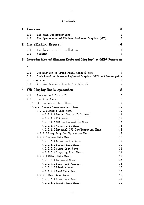
Contents1 Overview 31.1 The Main Specifications 31.2 The Appearance of Minimum Keyboard Display (MKD) 32 Installation Request 42.1 The location of Installation 42.2 Warning 43 Introduction of Minimum Keyboard Display’s (MKD) Function43.1 Description of Front Panel Control Keys 43.2 Back Panel of Minimum Keyboard Display (MKD) and Descriptionof Interfaces 63.3 Minimum Keyboard Display’s Subarea74 MKD Display Basic operation 84.1 Turn on and Turn off 84.2 Function Menu 84.2.1 The Vessel List Menu 94.2.2 Vessel Configuration Menu 104.2.2.1 Static Data Menu 104.2.2.1.1 Vessel Static Info menu 114.2.2.1.2 ETA menu 124.2.2.1.3 VHF Configuration Menu 134.2.2.1.4 Voyage Info Menu 134.2.2.1.5 External GPS Configuration Menu 164.2.2.2 Long Rang Configuration Menu 174.2.2.3 Alarm Data Menu 184.2.2.3.1 Relay Config Menu 194.2.2.3.2 Status List Menu 204.2.2.3.3 Alarm List Menu 214.2.2.3.4 Stopping List Menu 214.2.2.4 Other Data Menu 224.2.2.4.1 Password Menu 234.2.2.4.2 Self Test Function 234.2.2.4.3 Edition Menu 254.2.2.4.4 Baud Rate Menu 264.2.2.5 Reg. Area Menu 264.2.2.5.1 Area View Menu 274.2.2.5.2 Create Area Menu 284.2.3 SRMs Menu 294.2.3.1 Tx List Message Menu 304.2.3.2 Rx List Message 314.2.3.3 Send Message Menu 314.2.3.4 Long Range Menu 324.2.4 Display Setting 334.2.5 Plot Menu 344.2.6 OWNER DETIAL Menu 344.2.7 Alarm Information Dialog 365 Maintenance 366 Mounting 377 Installation 387.1 Transponder Unit 387.2 Display Unit 397.3 VHF Antenna 397.4 GPS Antenna 407.5 Junction Box 408 Wiring Input/Output connections 418.1 Power cable connections 418.2 Signal cable connections 418.2.1 Signal cable of the Transponder Unit 418.2.2 Signal cable of the Display Unit 428.2.3 Junction box 429 Transponder status LEDs 4410 Dimension 4510.1 Transponder Unit 4510.2 Display Unit 4510.3 Junction box 4611 Appendix 4611.1 Reference 4611.2 Serial Communication Interfaces 4711.2.1 Sensor input data and formats 4711.2.2 Input & output data and formats in IEC61162-1 471OverviewMinimum Keyboard Display (MKD) is a Display Unit of Automatic Identify System (AIS) which is designed by Advanced Aviation Company, a subsidiary of Shanghai Avionics Corporation. It transfers data with AIS to get the voyage information of own vessel and other vessels using RS422. It can help the vessels get higher efficiency and safety, and avoid traffic accidents.1.1The Main SpecificationsWorking Temperature: -15℃---+55℃Working Humidity: 20%---75%Power Supply: 24Vdc---+30%1.2The Appearance of Minimum Keyboard Display (MKD)2Installation Request2.1The location of InstallationMinimum Keyboard Display (MKD) and power supply should be installed indoor. Minimum Keyboard Display (MKD) should be convenient to be operated and observed.2.2WarningThe system should be away from heat and strong magnetic field. And the installation place should be dry.3Introduction of Minimum Keyboard Display’s (MKD) Function3.1Description of Front Panel Control Keys● Power Key---Turn on and off MKD, and need be hold about 5seconds.● System Key 【MENU 】 ---Exit current menu and back the upper menu.● Direction Keys 【▲▼◄►】---Move cursor up and down. ● Exit key 【ESC 】--- Exit current menu, return previous menu.● Confirmation Key 【OK 】 ---Enter or exit setting parameter. ● Alphanumeric Keys --- Input different parameter.● Function Keys---Different pages have different functions. (They are F1, F2, F3, F4, and F5 from left to right).[Power key][Alphanumeric keys][Function keys][ESC][OK] [MENU] [LCD][System keys] [Confirmation Key ][Exit key]3.2Back Panel of Minimum Keyboard Display (MKD) andDescription of InterfacesIntroduction:1: +24V 2: sky3: GNDJX1JX2 1: Y 3: A 5: GND2: Z 4: B1: Y 5: spare9 : Y 13: spare17: spare2: Z 6: spare10 : Z 14: spare18: spare3: A 7: spare11 : A 15: spare19: spare4: B 8: spare12: B 16: spareJX33.3 Minimum Keyboard Display’s SubareaiN 0*0.000*N 10*0.000*E1MMSI Name RNG BRG TYPECONFIGSRMsSHOW SETPLOTOWNER DETAIL[A] Show that Automatic Identify System (AIS) is using GPS. [B] Show that if there are some alarm information. [C] Show that if there are some safety messages.[D] Show if the communication between Minimum Keyboard Display and Automatic Identify System (AIS) is OK.[E] Display the content of current menu. [F] Area of Function Key.[G] Show the current vessels. (Just list the number of vessels and the serial of vessels).[H] Display the status of current vessel.[B][H][E][G][F][A][C][D]4 MKD Display Basic operation4.1 Turn on and Turn off● Turn MKD on: Check the connection, and make sure that the connection is right,and then press the power key and hold it about 5 seconds.● Turn MKD off: Press the power key and hold it about 5 seconds when the MKD ison.4.2 Function Menu(Power on4.2.1 The Vessel List MenuThe cursor shows the vessel which is chosen.Move the cursor to choose different vessels with Up and Down key 【▲】【▼】. Select the pages with Left and Right key【◄】【►】.See the detail menu of chosen vessel with【OK】.4.2.2Vessel Configuration MenuEnter Vessel Configuration Menu page with 【F1】. As follows:Enter Static Data Menu With 【F1】.Enter Long Range menu with 【F2】.Enter Alarm Data menu with 【F3】.Enter Other Data menu with 【F4】.Enter Reg. Area Menu with 【F5】.4.2.2.1Static Data MenuEnter Static Data page from Local vessel configuration page with 【F1】. As follows:Enter Static Data menu with 【F1】.Enter ETA Menu with 【F2】.Enter VHF Configuration menu with 【F3】.Enter Voyage Information menu with 【F4】Enter External GPS Configuration menu with 【F5】4.2.2.1.1Vessel Static Info menuEnter Static Information menu to set MMSI, IMO, name, number, and dimension of own vessel with 【F1】. As follows:Move the cursor to select different items with Up and Down Keys 【▲】【▼】. Enter or exit Content Setting menu with 【OK】.Save and exit with 【F1】.Delete former notation with 【F5】.4.2.2.1.2ETA menuEnter Estimate Time Arrived page from Vessel Configuration page with 【F2】. As follows:Move cursor up and down to select different items with Up and Down keys 【▲】【▼】. Enter or exit Content Setting menu with 【OK】.Save this setting and exit with 【F1】.4.2.2.1.3VHF Configuration MenuEnter VHF Configuration page from Vessel Configuration page with 【F3】.Move cursor up and down to select different item with 【▲】【▼】.Enter or exit Content Setting Menu with 【OK】.Save this setting and exit with 【F1】.Delete the one notation before cursor with 【F5】.4.2.2.1.4Voyage Info MenuEnter Voyage Information Setting page from Vessel Configuration page with 【F4】. As follows:Move cursor up and down to select different item with 【▲】【▼】. Enter or exit Content Setting Menu with 【OK】.Save this setting and exit with 【F1】.Delete the one notation before cursor with 【F5】.Voyage StateType of Ships-----Special ShipType of ships——Other ShipDG: Dangerous GoodsHS: Harmful SubstanceMP: Marine Pollutants*: Ship type should be build by first and second Number.4.2.2.1.5External GPS Configuration MenuEnter External GPS Configuration Menu from Vessel Configuration page with 【F5】. This can set the dimension of External GPS. As Follows:Move cursor to choose different item with 【▲】【▼】Enter or exit Content setting Menu with 【OK】Save and exit with 【F1】Delete the notation before Cursor with 【F5】Press 【ESC】to Return upper menu, and press 【MENU】to Return Main page.4.2.2.2Long Rang Configuration MenuEnter Long Rang Configuration page from Vessel Configuration page with 【F2】. As follows:Save and exit with 【F1】.Set the mode of reply is automatic mode with 【F2】Set the mode of reply is manual mode with 【F3】Press number 0-9 to choose the what to replyReturn upper menu with 【ESC】, and Return Main page with 【MENU】4.2.2.3Alarm Data MenuEnter Alarm Data page from Vessel Configuration page with 【F3】. As follows:Enter Relay Setting Menu with 【F1】Enter State Information Setting Menu with 【F2】Enter Alarm List menu with 【F3】Enter Stopping Information menu with 【F5】Return upper menu with 【ESC】, and Return Main page with 【MENU】4.2.2.3.1Relay Configuration MenuEnter Relay Configuration page from Alarm Data page with 【F1】Press Number keys 1-6 to choose if Relay Alarm turns on and turns off under special conditions. “on” means turn on the alarm and “off” means turn off the alarm.Press【F5】to enter the page as follows:Save and exit with 【F1】Enter former page of this menu with 【F5】Return upper menu with 【ESC】, and Return Main page with 【MENU】4.2.2.3.2Status List MenuEnter Status List page from Alarm Data page with 【F2】. As follows:Move to former page of next page with 【F4】【F5】or 【◄】【►】Return upper menu with 【ESC】, and Return Main page with 【MENU】4.2.2.3.3Alarm List MenuEnter Alarm List page from Alarm Data with 【F3】Move to former page of next page with 【F4】【F5】or 【◄】【►】Return upper menu with 【ESC】, and Return Main page with 【MENU】4.2.2.3.4Stopping List MenuEnter Stopping List page from Alarm Data page with 【F5】. As follows:Move to former page of next page with 【F4】【F5】or 【◄】【►】Return upper menu with 【ESC】, and Return Main page with 【MENU】4.2.2.4Other Data MenuEnter Other Data page from Vessel Configuration page with 【F4】. As follows:Enter Password menu with 【F1】Enter Self Test menu with 【F2】Enter Edition Menu with 【F3】Enter Chinese and English Switch with 【F4】Return upper menu with 【ESC】, and Return Main page with 【MENU】4.2.2.4.1Password MenuEnter Password page from Other Data page with 【F1】. Setting password is used to protect the Local Identifier Code and IMO. As follows:Move cursor up and down with 【▲】【▼】Enter and exit Content Setting with 【OK】Save the password and exit with 【F1】Delete a notation with 【F5】Return upper menu with 【ESC】, and Return Main page with 【MENU】4.2.2.4.2Self Test FunctionEnter Self Testing page from Other Data page with 【F2】Display peripherals sensor’s state as follows with 【F1】Return upper menu with 【ESC】, and Return Main page with 【MENU】Press 【F2】to switch between white and black screen.Enter Keyboard Test page with 【F3】IN 31º10.305’ N121º23.855’ EPress the button one another , and if the corresponding box turns to “”, it means this button can work normally.Press 【ESC】three times to exit.4.2.2.4.3Edition MenuEnter Edition menu from Other setting menu to tell the user edition information with 【F3】. As follows:Return upper menu with 【ESC】, and Return Main page with 【MENU】4.2.2.4.4Baud Rate MenuEnter Baud Rate page from Other Data with 【F5】. As follows:Move cursor with 【▲】【▼】Choose baud rate with 【◄】【►】Save with 【F1】, and baud rate will changedReturn upper menu with 【ESC】, and Return Main page with 【MENU】4.2.2.5Reg. Area MenuEnter Regional Area page from Vessel Configuration page with 【F5】. As follows:Enter Area View Menu with 【F1】Enter Create Area menu with 【F3】Return upper menu with 【ESC】, and Return Main page with 【MENU】4.2.2.5.1Area View MenuEnter Area View page from Area Regional Area page with 【F1】. As follows:Return upper menu with 【ESC】, and Return Main page with 【MENU】.4.2.2.5.2Create Area MenuEnter Create Area page from Regional Area page to set the latitude , attitude and transition area with 【F3】. As follows:Move cursor up and down with 【▲】【▼】.Enter Setting page with 【OK】.Input some data with 【◄】【►】.Enter next page area setting page with【F5】. As follows:Save and exit with 【F1】Delete the input data with 【F5】during edit the channel number Return upper menu with 【ESC】, and Return Main page with 【MENU】4.2.3 SRMs MenuEnter Send Message page in main page with【F2】, as follows:4.2.3.1Tx List Message MenuEnter Tx List Message Menu in SRMs page with【F1】. In this page we can see the lately seven safety message. As follows:Back the upper menu with【F5】.See the details of the current message with【F1】the cursor puts on.4.2.3.2Rx List MessageEnter Rx List Message Menu in SRMs Page with【F2】. In this page we can see the lately seven safety short message. As follows:Back upper menu with【F5】.See the details of current short message with【F1】the cursor puts on.4.2.3.3Send Message MenuEnter Send Message page in SRMs page with 【F3】. In this page we can send safety short message.The location cursor put on is item which can be edited.Select the content with Up and Down key 【▲】【▼】.Enter and exit Content Input page with 【OK】.In Content Input page edit short message with number keys and notation key. Send the short message with 【F1】<sending> after edition.Delete former notation or number with 【F5】.Send message with 【F1】.4.2.3.4Long Range MenuEnter Long Rang page with 【F5】. As follows:Refuse replying remote control information with 【F2】.Enter remote reply menu with 【F1】. In this page different kind of Number keys can choose different function.4.2.4 Display SettingEnter Display Setting from Main page with 【F3】. Press 【◄】【►】 to adjust brightness. As Follows:4.2.5 Plot MenuEnter Plot page from MKD Work Main page with 【F4】. As follows:Zoom in and Zoom out chart with 【F4】【F5】respectively.Select different distant vessel with 【◄】【►】, and the basic information of chosen board is displayed on the right hand of LCD display.4.2.6 OWNER DETIAL MenuEnter Owner Detail page from MKD Work Main Page with 【F5】. As follows:See the next page of native information with 【F5】. As follows:See the former page of local vessel information with 【F5】.Exit this menu with 【ESC】.4.2.7 Alarm Information DialogWhen MKD receives the alarm message, MKD will pop dialog. And it will exit and return Main page when the user confirms it. As follows:IN 31º10.305’ N 2121º23.855’ E 48ALARM!ALARM ID:025ALARM Description:AIS: external EPFS lostALARM Time:00:25(Please press [OK] to confirm!)CONFIG SRMs SHOWSET PLOT OWNERDETAILPress 【OK】to Confirm alarm message.5MaintenanceWe should overhaul the device every several days to make sure that it can work normally.1.The range of the power must be in 18V~28V DC.2.When something is wrong with the equipment, the reason must be find out.3.Nobody is allowed to open the equipment except the qualified repairman, avoidingbe shocked by the electricity, or make other problems to the equipment. 4.Nobody is allowed to vary the component of the equipment except the qualifiedrepairman.5.When ensure some problem of the equipment, please contact with the dealer andask for repair service.6MountingWhen unpacking the equipment, please check that the following is included in the delivered package. If any of the parts are missing, please contact the dealer.Standard package:Optional accessories7 Installation7.1 Transponder UnitWhen mounting the Transponder Unit please consider the following: ● Mounting the unit on a wall, in the ceiling or on top of a bench.● The range of the operation temperature is 15-to 55+, and the temperature andhumidity should be moderate and stable.● Select a location away from excessive heat sources. ● Avoid areas where are high flow of humid salt air. ● Avoid high levels of vibrations and shocks.● Ensure that there is enough airflow to avoid high ambient temperatures.● The unit can affect magnetic compasses. Use a minimum of 0.2m to nearest magneticcompass.● Install the Transponder as close as possible to VHF/GPS antennas to minimizecable lengths.● Leave a clearance around the Transponder to facilitate service and installation.7.2 Display UnitWhen mounting the Display Unit please consider the following: ● Mounting the unit on a wall, in the ceiling or on top of a bench.● The range of the operation temperature is 15-to 55+, and the temperature andhumidity should be moderate and stable.● Select a location away from excessive heat sources. ● Avoid areas where are high flow of humid salt air. ● Avoid high levels of vibrations and shocks. ● Avoid mounting the Display in direct sunlight.● Ensure that there is enough airflow to avoid high ambient temperatures. The unit can affect magnetic compasses. Use a minimum of 0.2m to nearest magnetic compass.7.3 VHF AntennaWhen mounting the VHF antenna please consider the following:● The objective for the AIS VHF antenna is to see the horizon freely through 360degrees.● The AIS VHF antenna should be placed in an elevated position that is as freeas possible with a minimum of 2 meters in horizontal direction from constructions made of conductive materials.● The AIS VHF antenna should be installed safely away from interfering high-powerradiating sources like radar and other transmitting radio antennas, preferablyat least 3 meters away from an out of the transmitting beam.●There should not be more than one antenna on the same level. The AIS VHF antennashould be mounted directly above or below the ship’s primary VHF radiotelephone antenna, with no horizontal separation and with a minimum of 2 meters vertical separation. If it is located on the same level as other antennas, the distance apart should be at least 10 meters.7.4 GPS AntennaWhen mounting the GPS antenna please consider the following:●The GPS antenna must be installed where it has a clear view of the sky. Theobjective is to see the horizon freely through 360 degrees with a vertical observation of 5 to 90 degrees above the horizon.●Locate the GPS antenna at least 3 meters away from and out of the transmittingbeam of high-power transmitters such as S-Band Radar and/or Inmarsat systems.7.5Junction BoxWhen mounting the Junction box please consider the following:●Locate the Junction box at least 3 meters away from the Transponder Unit, orthe Display Unit, or the Power System.●The Junction box must be keep out of the interfering source.●Caution on waterproof.●There are 4 cushions at the bottom of the Junction box, if you wanted fastenthe box on the wall, you can uninstall these cushions.The platform of the Junction box inside8Wiring Input/Output connections8.1Power cable connectionsThe Power of the Transponder Unit & Display Unit is 24V DC, there are Negative polar & Positive polar inside the Junction box, please notice the polarity when connecting the power. The range of the power is 18V~28V DC.8.2Signal cable connections8.2.1 Signal cable of the Transponder UnitThe pilot plug is used to the signal cable of the Transponder Unit, please parallel the plug with the socket at the red remark When connecting.8.2.2 Signal cable of the Display UnitThere are some sockets at the back of the Display Unit, the biggest one is used by the Signal cable, there are remarks in the plug & socket, please parallel them when connecting.8.2.3Junction boxThe definition of the interfaces of the Junction boxThere are 4 signal wires: TX+, TX-, RX+, RX- in each interface, the TX+ & TX- are the signal wires for the transmitting, and the RX+ & RX-are used for the reception.9Transponder status LEDs●The PWR LED indicates that power is applied to the Transponder.● A flashing of the ERR LED indicates that there is something wrong with thetransponder.● A flashing of the RX LED indicates that the Transponder is receiving data.● A flashing of the TX LED indicates that the Transponder is transmitting on theradio link.The status LEDs on the panel of the Transponder Unit10 Dimension10.1Transponder UnitUnits:mm 10.2Display Unit10.3Junction box11Appendix11.1Reference●ITU-RM.1371-1●IEC61993-2●IEC61162-1●IEC61162-2●IEC60945●AWAIS-1 MKD instruction11.2Serial Communication Interfaces11.2.1Sensor input data and formats11.2.2Input & output data and formats in IEC61162-1。
AMM手册缩写

AMM⼿册缩写ABBREVIATION SIGNIFICATIONA AmberA AlternateA/C AircraftA/D Analog/DigitalA/DC Analog-to-Digital ConverterA/R Audio ReproducerA/SKID Anti-SkidA/THR AutothrustA/XFMR Autotransformer ⾃耦变压器ABCU Alternate Braking Control UnitAC Alternating CurrentACARS Aircraft Communication Addressing and Reporting System ACC Active Clearance ControlACCEL Acceleration/AccelerateACCLRM AccelerometerACCU ACCUMULATORACMM Abbreviated Component Maintenance ManualACMS Aircraft Condition Monitoring SystemACP Area Call PanelACP Audio Control PanelACQN AcquisitionACSC Air Conditioning System ControllerACT ActiveACTR ActuatorADC Air Data ComputerADF Automatic Direction FinderADIRS Air Data/Inertial Reference SystemADIRU Air Data/Inertial Reference UnitADM Air Data ModuleADR Air Data ReferenceADS Air Data SystemADV AdvisoryAEVC Avionics Equipment Ventilation ComputerAF Audio FrequencyAFS Automatic Flight SystemAGB Accessory GearboxAGC Automatic Gain ControlAGL Above Ground LevelAGW Actual Gross WeightAIL AileronAIM Aircraft Integrated MaintenanceAIP Attendant Indication PanelALI Airworthiness Limitation ItemALIGN AlignmentALT AltitudeALTM AltimeterALTN Alternate, AlternativeAM Amplitude ModulationAMM Aircraft Maintenance ManualAMS Aerospace Material Specification航材规范AMU Audio Management UnitANI Analog InputANN AnnunciatorANN LT Annunciator LightANO Analog OutputANT AntennaAOA Angle-of-AttackAOC Airline Operational ControlAOC Airline Operational ControlABBREVIATION SIGNIFICATIONAP AutopilotAP/FD Autopilot/Flight DirectorAPPR ApproachAPPU Asymmetry Position Pick Off UnitAPU Auxiliary Power UnitARINC Aeronautical Radio Incorporated航空⽆线电公司ARPT AirportASCII American Standard Code for Information Interchange美国信息交换标准代码ASI Airspeed IndicatorASIC Application Specific Integrated Circuits特定⽤途集成电路ASM Aircraft Schematics ManualASP Audio Selector PanelASSY Assembly 组件ATA Air Transport Association of AmericaATC Air Traffic ControlATE Automatic Test EquipmentATLAS Abbreviated Test Language for All SystemsATS Autothrottle SystemATSU Air Traffic Service UnitATT AttitudeATTND AttendantAUTO AutomaticAUX AuxiliaryAVAIL AvailableAVNCS AvionicsAWM Aircraft Wiring ManualAWY AirwayAZ AzimuthB BlueBARO Barometric ⽓压的BAT BatteryBCD Binary Coded DecimalBCL Battery Charge Limiter电瓶充电限制器BFO Beat Frequency Oscillator差频振荡器BGM Boarding MusicBITE Built-in Test EquipmentBMC Bleed Monitoring ComputerBNR Binary ⼆进制BOT Begin of TapeBP Bottom PlugBRG Bearing ⽅位⾓BRK BrakeBRKR BreakerBRKT Bracket 托架BRT Bright, BrightnessBSCU Braking/Steering Control UnitBTC Bus Tie Contactor汇流条连接接触器BTMU Brake Temperature Monitoring UnitBTN Button 按钮BTR Bus Tie RelayBU Battery UnitBUS BusbarBYDU Back-Up Yaw Damper Unit 备⽤偏航阻尼组件C CloseC Celsius, CentigradeC/B Circuit BreakerC/L Check ListCAB CabinCAM Cabin Assignment ModuleCAPT CaptainCAS Calibrated Air Speed修正表速CAUT CautionABBREVIATION SIGNIFICATIONCAUT LT Caution LightCBMS Circuit Breaker Monitoring SystemCBMU Circuit Breaker Monitoring UnitCCS Cabin Communications SystemCCW Counter Clockwise逆时针CDP Compressor Discharge PressureCDU Control and Display UnitCFDIU Centralized Fault Display Interface UnitCFDS Centralized Fault Display SystemCFMI CFM InternationalCFRP Carbon Fiber Reinforced Plastic 碳纤维强化塑料CG Center of GravityCGCS Center of Gravity Control System重⼼控制系统CHAN ChannelCHG ChangeCIDS Cabin Intercommunication Data SystemCK CheckCKPT CockpitCKT CircuitCL Center LineCLB ClimbCLG Centerline Landing GearCLOG Clogging堵塞CLR ClearCMC Central Maintenance Computer中央维护计算机CMD Command 命令,指令CMM Component Maintenance ManualCMR Certifification Maintenance Requirements 取证维护要求CNTOR Contactor 开关CO Company 公司COM CommunicationCOMPT Compartment 间隔COMPTR Comparator 精密仪器COND Conditioned, Conditioning 状态CONFIG Configuration 配置,布局,结构CONT ControllerCONV ConverterCOOL Cooling, CoolerCOS Cosine 余弦CPC Cabin Pressure ControllerCPLR CouplerCPMS Cabin and Passenger Management System客舱和旅客管理系统CPMU Cabin Passenger Management UnitCPRSR Compressor 压缩机CPU Central Processing UnitCRC Continuous Repetitive ChimeCRG CargoCRS CourseCRT Cathode Ray TubeCRZ CruiseCSD Constant Speed Drive恒速传动装置CSM/G Constant Speed Motor/GeneratorCSTR ConstraintCSU Command Sensor UnitCT Current Transformer 电流互感器CTL CentralCTL ControlCTR CenterCU Control UnitCUDU Current Unbalance Detection Unit电流不平衡探测组件CUR CurrentCVR Cockpit Voice RecorderCVR Cockpit Voice RecorderABBREVIATION SIGNIFICATIONCVT Center Vent Tube 中通⽓管CW ClockwiseD/D Engine Out Drift Down Point发动机失效漂降点D/O Description and Operation说明与⼯作DA Drift Angle 偏离⾓DAC Digital to Analog ConverterDAR Digital ACMS RecorderDC Direct CurrentDDRMI Digital Distance and Radio Magnetic IndicatorDEC Declination倾斜DECEL Decelerate 减速DECR Decrease 减少DEF Definition 定义DELTA P Differential Pressure 压差DES Descent 下降DEST Destination ⽬的地DET Detection, DetectorDEU Decoder/Encoder UnitDEV Deviation 偏差DFDR Digital Flight Data RecorderDFDRS Digital Flight Data Recording SystemDGI Digital InputDGO Digital OutputDH Decision Height决断⾼度DIA Diameter 直径DIFF Differential差分DIM Dimming, DimensionDIR Direction, Direct, DirectorDISC Disconnect, DisconnectedDIST DistanceDMA Direct Memory Access直揍获取存储器DMC Display Management ComputerDME Distance Measuring EquipmentDMU Data Management UnitDN DownDNLK Downlock放下锁DPDT Double Pole/Double Throw双极/双置DPI Differential Pressure IndicatorDR Dead Reckoning 航位推算DRVR Driver 驱动器DSCRT DiscreteDSDL Dedicated Serial Data Link专⽤系列数据链DSI Discrete InputDSO Discrete OutputDSPL DisplayDTG Distance to Go待飞距离DTMF Dual Tone Multiple Frequency双⾳多频DU Display UnitE EastEBU Engine Built-up UnitECAM Electronic Centralized Aircraft MonitoringECB Electronic Control Box (APU)ECM Engine Condition MonitoringECMU Electrical Contactor Management Unit电路接触器管理系统ECON Economy经济ECP Ecam Control PanelECS Environmental Control System环境控制系统ECU Electronic Control UnitEEC Electronic Engine Control电⼦发动机控制EEPROM Electrically Eraseable Programmable Read Only Memory电清除程序可控只读存储器EFCS Electrical Flight Control SystemEFCS Electrical Flight Control SystemABBREVIATION SIGNIFICATIONEFF Effective, EffectivityEFIS Electronic Flight Instrument SystemEGIU Electrical Generation Interface Unit发电接⼝组件EGT Exhaust Gas Temperature排⽓温度EIS Electronic Instrument SystemEIU Engine Interface UnitEIVMU Engine Interface and Vibration Monitoring Unit发动机接⼝和振动监控组件ELEC Electric, Electrical, ElectricityELEV Elevation, ElevatorEMER EmergencyEMI Electromagnetic Interference 电磁⼲扰END Endurance 续航时间ENG EngineEO Engine Out 发动机失效EOSID Engine Out Standard Instrument Departure发动机失效标准仪表离港EOT End of Tape录⾳结束EPC External Power Contactor外部电源接触器EPGS Electrical Power Generation System发电系统EPR Engine Pressure Ratio发动机压⼒⽐EPROM Erasable Programmable Read Only MemoryEPSU Emergency Power Supply Unit应急电源供电组件EQPT EquipmentESS Essential 重要EST Estimated预计的ETA Estimated Time of Arrival预达时间ETE Estimated Time en Route 预计航路时间ETP Equal Time Point 等时点EVAC Evacuation 撤离EWD Engine/Warning Display发动机/警告指⽰EXC Excitation, Excite励磁,产⽣励磁EXCESS Excessive 过多的EXT Exterior, ExternalF FahrenheitF-PLN Flight PlanF/O First OfficerFAC Flight Augmentation ComputerFADEC Full Authority Digital Engine Control 全效能数字电⼦控制FAIL Failed, FailureFAP Forward Attendant PanelFC Fully Closed 全关FCDC Flight Control Data Concentrator 飞⾏数据集中器FCMS Fuel Control Monitoring System 燃油控制和监控计算机FCOM Flight Crew Operating Manual 飞⾏机组使⽤⼿册FCPC Flight Control Primary Computer飞⾏操纵主计算机FCSC Flight Control Secondary Computer飞⾏操纵辅助计算机FCTN FunctionFCU Flight Control UnitFCV Flow Control ValveFD Flight DirectorFDBK Feedback 反馈FDIU Flight Data Interface UnitFDU Fire Detection UnitFE Flight Envelope 飞⾏包线FF Fuel Flow 燃油流量FG Flight GuidanceFIDS Fault Isolation and Detection SystemFIFO First Input/First Output 先进/先出FIG FigureFIN Functional Item NumberFIR Full Indicator Reading 全指⽰器读数FL Flight LevelFLEX FlexibleFLEX FlexibleABBREVIATION SIGNIFICATIONFLP FlapFLT FlightFM Flight ManagementFMA Flight Mode Annunciator飞⾏⽅式指引FMC Flight Management ComputerFMGC Flight Management and Guidance ComputerFMGS Flight Management and Guidance SystemFMS Flight Management SystemFMU Fuel Metering Unit燃油计量装置FMV Fuel Metering ValveFO Fully OpenFOB Fuel On Board机载燃油FOD Foreign Object DamageFPA Flight Path Angle飞⾏航经⾓FPEEPMS Floor Proximity Emergency Escape Path Marking System FPPU Feedback Position Pick-off Unit回输位置传感组件FPV Flight Path Vector飞⾏航经引导FQ Fuel QuantityFQI Fuel Quantity Indicating/Indication/IndicatorFR Frame结构,隔框FREQ FrequencyFRU Frequency Reference Unit频率基准组件FRV Fuel Return ValveFSB Fasten Seat BeltsFW Failure WarningFWC Flight Warning ComputerFWD ForwardFWS Flight Warning SystemG GreenG/S Glide SlopeGA Go-Around 复飞GALY Galley 厨房GAPCU Ground Auxiliary Power Control UnitGalleyGCR Generator Control RelayGCU Generator Control UnitGEN GeneratorGLC Generator Line Contactor发电机馈线接触器GLR Generator Line RelayGMT Greenwich Mean Time格林尼治时钟GND GroundGPCU Ground Power Control UnitGPS Global Positioning SystemGPU Ground Power UnitGPWC Ground Proximity Warning Computer近地警告计算机GPWS Ground Proximity Warning SystemGRP Geographic Reference Point地⾯/地理坐标基准点GRU Ground Refrigeration Unit 地⾯冷冻车GS Ground SpeedGSE Ground Support Equipment地⾯⽀援设备GW Gross WeightH Hot (Electrical Point)HCU Hydraulic Control UnitHDG HeadingHEGS Hydraulic Electrical Generating System液电产⽣系统HF High FrequencyHI HighHLAC High Level Alternating Current Voltage⾼压交流电HLDC High Level Direct Current VoltageHMU Hydromechanical Unit液压机械组件HP High PressureHPC High Pressure CompressorHPC High Pressure CompressorABBREVIATION SIGNIFICATIONHPT High Pressure TurbineHPTACC High Pressure Turbine Active Clearance Control⾼压涡轮主动间隙控制HS High SpeedHSI Horizontal Situation IndicatorHSMU Hydraulic System Monitoring UnitHUDC Head Up Display Computer平视显⽰计算机HYD Hydraulic 液压I/O Input/OutputI/P Intercept ProfileI/P InputIAE International Aero Engines国际航空发动机公司IAS Indicated AirspeedIBR Integral Bladed RotorID Inside DiameterIDENT Identification, Identifier, IdentifyIDG Integrated Drive Generator整体驱动发电机IDGS Integrated Drive Generator SystemIGB Inlet Gear Box进⼝齿轮箱IGN Ignition点⽕IGV Inlet Guide Vane进⽓导向叶⽚ILS Instrument Landing System (LOC and G/S)IMM ImmediateINB Inbound向台飞⾏的INBD Inboard归航的;向台(电)飞⾏的INCR Increment 增加IND IndicatorINFO InformationINHIB Inhibition, Inhibit, Inhibited 抑制INIT Initial(ization) 初始化INOP InoperativeINR InnerINT Interrupt中断INTCP Intercept拦截INTFC InterfaceINTL InternalINTRG Interrogate, Interrogator 询问INV Inverter静变流机IP Intermediate PressureIPC Illustrated Parts CatalogIPPU Instrumentation Position Pick-off Unit仪表位置传感组件IR Inertial ReferenceIRS Inertial Reference SystemISA International Standard Atmosphere国际标准⼤⽓ISO International Standardization Organisation国际标准化组织ISOL IsolationIVS Inertial Vertical Speed惯性垂直速度JAM Jammed, Jamming卡阻的,卡阻,⼲扰JAR Joint Airworthiness Requirements联合航空条例L LeftL LengthL/G Landing GearLA Linear Accelerometer线性加速器LAT Lateral 横向LAT Latitude 维度LAV Lavatory 厕所LBP Left Bottom Plug 左下插头LCD Liquid Crystal DisplayLCIT Load Compressor Inlet Temperature负载压⽓机进⼝温度LDG LandingLE Leading Edge前沿LED Light Emitting DiodeLED Light Emitting DiodeABBREVIATION SIGNIFICATION LGCIU Landing Gear Control and Interface UnitLIM Limit, Limitation, Limiting, LimiterLKD LockedLL Lat/LongLLDC Low Level Direct Current VoltageLMP Left Middle PlugLNG LongLMS Leakage Measurement System渗漏测量系统LO LowLOC Localizer航向信标台LONG Longitude 经度LONGN Longeron 纵轴LOP Low Oil PressureLP Low PressureLPC Low Pressure CompressorLPT Low Pressure TurbineLPTACC Low Pressure Turbine Active Clearance ControlLRU Line Replaceable UnitLS LoudspeakerLSB Least Significant Bit最低有效位LSI Large Scale Integration⼤刻度积分的LT LightLTP Left Top PlugLV Low VoltageLVDT Linear Variable Differential Transducer线性可变差动变压器LVL LevelLW Landing WeightLWR LowerMAC Mean Aerodynamic Chord平均空⽓动⼒弦MAG MagneticMAINT MaintenanceMAN ManualMAX MaximumMCDU Multipurpose Control & Display UnitMCL Maximum Climb最⼤爬升率MCT Maximum Continuous ThrustMCU Modular Concept Unit模块式概念组件MDA Minimum Descent Altitude 最⼩决断⾼度MDDU Multipurpose Disk Drive UnitMECH Mechanic, Mechanical, MechanismMED MediumMES Main Engine Start 主发动机启动MI Magnetic IndicatorMIC MicrophoneMICBAC Micro-System Bus Access Channel 微系统总线存取通道MID MiddleMIN MinimumMISC Miscellaneous 各式各样的,其他MKR Marker (radio) BeaconMLA Maneuver Load AlleviationMLG Main Landing GearMLI Magnetic Level Indicator 磁⽔平指⽰器MLS Microwave Landing SystemMLW Maximum Design Landing Weight 最⼤着陆重量MMEL Master Minimum Equipment ListMMO Maximum Operating Mach 马赫⽅式的最⼤操纵速度MMR Multi Mode ReceiverMODLTR ModulatorMON Monitor, Monitoring, MonitoredMORA Minimum Off Route Altitude 最低偏航⾼度MOT Motor, MotorizedMPD Maintenance Planning Document 维护计划⽂件MPD Maintenance Planning Document 维护计划⽂件ABBREVIATION SIGNIFICATIONMRBR Maintenance Review Board Report维修审查委员会报告MRW Maximum Ramp Weight最⼤停机重量MSA Minimum Safe Altitude 最⼩安全⾼度MSB Most Significant BitMSG MessageMSL Mean Sea LevelMSU Mode Selector Unit (IRS) ⽅式选择组件MSW Microswitch 微动开关MTBF Mean Time Between FailureMTBUR Mean Time Between Unscheduled Removals ⾮定期拆卸平均MTG MountingMTO Maximum Take-Off 最⼤起飞MTOGW Maximum Takeoff Gross WeightMTOW Maximum Design Takeoff WeightMU Management Unit 管理组件MUX Multiplex, Multiplexer 多路器MVT Movement 运动,动态MZFW Maximum Design Zero Fuel WeightN Normal, NorthN/A Not ApplicableN/P Next PageN/W Nose WheelN/WS Nose Wheel SteeringNAC Nacelle 发动机短舱;吊舱NAS Navy and Army StandardNAV NavigationNAVAID Navigation AidNBPT No Break Power Transfer 不间断供电转换NC Normally ClosedNCD No Computed DataND Navigation DisplayNDB Non-Directional BeaconNEG NegativeNLG Nose Landing GearNMI Non Maskable Interrupt⾮屏蔽性中断No NumberNO Normally OpenNO Normal Operation in SSMNORM NormalNS No SmokingNUM NumericalNVM Non-Volatile Memory⾮易失存储器N1Low Pressure Rotor SpeedN2High Pressure Rotor SpeedO OpenO/P OutputOAT Outside Air Temperature外界⼤⽓温度OBRM On Board Replaceable Module机上可更换组件OC Open CircuitOC OvercurrentOD Outside Diameter 外直径OF OverfrequencyOFST OffsetOGV Outlet Guide VaneOHU Optical Head UnitOIT Oil Inlet TemperatureOK CorrectOMS Onboard Maintenance System机载维修系统OOT Oil Outlet Temperature滑油出⼝温度OP OperationalOPP Opposite相反的,相对的,对⾯的OPS Operation操作OPS Operation操作ABBREVIATION SIGNIFICATION OPT Optimum可选择的OPV Overpressure ValveOUTBD OutboardOVBD OverboardOVHD OverheadOVHT OverheatOVLD OverloadOVRD OverrideOVSP OverspeedOXY OxygenP/B PushbuttonP/BSW Pushbutton SwitchPA Passenger AddressPATS Passenger Air-to-Ground Telephone SystemPAX PassengerPC Pack ControllerPCB Printed Circuit Board印刷电路板PCM Pulse Code Modulation脉冲编码调谐PCU Passenger Control UnitPCU Power Control UnitPD Pitch DiameterPED Pedestal操纵台PERF PerformancePES Passenger Entertainment (System)PF Power FactorPFD Primary Flight DisplayPH PhasePHC Probe Heat ComputerPIU Passenger Information UnitPMA Permanent Magnet Alternator永磁交流发电机PMG Permanent Magnet Generator永磁产⽣器PN Part NumberPNL PanelPOB Pressure-Off BrakePOR Point of RegulationPOS PositionPOT Potentiometer 电位计PPH Pounds per hourPPM Parts per millionPPOS Present Position现在位置PR Power Ready RelayPRAM Prerecorded Announcement and Music⼴播预录⾳机PREAMP PreamplifierPRED PredictionPRESEL Preselector/PreselectionPRESS Pressure, Pressurization, PressurizePREV PreviousPRIM PrimaryPROC T Procedure TurnPROF ProfilePROG ProgressPROM Programmable Read Only MemoryPROT ProtectionPROX Proximity 接近PRR Power Ready RelayPSCU Proximity Switch Control Unit 邻近电门控制组件PSDU Power Supply Decoupling Unit 供电去耦组件PSI Pound per Square Inch 每平⽅英⼨PSIA Pound per Square Inch Absolute每平⽅英⼨绝对压⼒PSIG Pound per Square Inch Gauge每平⽅英⼨重⼒PSS Passenger Services SystemPSS Passenger Services System ABBREVIATION SIGNIFICATION PSU Passenger Service UnitPT PointPTC Positive Temperature CoefficientPTT Push to TestPTT Push-to-TalkPU Panel UnitPVI Paravisual IndicatingPVIS Passenger Visual Information SystemPWR PowerP&W Pratt & WhitneyQ Pitch RateQAD Quick-Attach-DetachQAR Quick Access RecorderQAT Quadruple ARINC TransmitterQEC Quick Engine ChangeQFE Field Elevation Atmospheric PressureQFU Runway HeadingQNE Sea Level Standard Atmosphere PressureQNH Sea Level Atmospheric PressureQTY QuantityR RedR RightR/I Radio/InertialRA Radio Altimeter, Radio AltitudeRAC Rotor Active ClearanceRACC Rotor Active Clearance ControlRACSB Rotor Active Clearance Start BleedRAD RadioRAM Random Access MemoryRAT Ram Air TurbineRBP Right Bottom PlugRC Repetitive ChimeRCC Remote Charge ConverterRCCB Remote Control Circuit BreakerRCDR RecorderRCL Recall 撤销RCPT ReceptacleRCPTN ReceptionRCVR ReceiverRECIRC Recirculate, RecirculationRECT RectifierRED ReductionREF ReferenceREFUEL RefuelingREG RegulatorREL ReleaseRES ResistanceRET ReturnREV ReverseREV Revise, RevisionRF Radio FrequencyRFS Regardless of Feature SizeRLA Reverser Lever AngleRLS Remote Light SensorRLY RelayRMP Radio Management PanelRNG RangeROM Read Only MemoryRPLNT RepellentRPM Revolution per MinuteRQRD RequiredRST ResetRSV ReserveRSV ReserveABBREVIATION SIGNIFICATION RSVR ReservoirRTE RouteRTN ReturnRTP Right Top PlugRTS Return to SeatRUD RudderRVDT Rotary Variable Differential TransducerRVR Runway Visual RangeRWY RunwayS SouthS/C Step ClimbS/D Step DescentSAF SafetySAT Static Air TemperatureSB Service BulletinSC Single ChimeSD System DisplaySDAC System Data Acquisition ConcentratorSDCU Smoke Detection Control UnitSDN System Description NoteSEB Seat Electronic BoxSEC SecondarySEL Select, Selected, Selector, SelectionSELCAL Selective Calling SystemSFCC Slat Flap Control ComputerSH ABS Shock AbsorberSHED SheddingSHT ShortSIC System Isolation Contactor 系统隔离接触器SID Standard Instrument Departure标准仪表离场SIG SignalSLT SlatSMK SmokeSN Serial NumberSOL SolenoidSOV Shut-Off ValveSPD SpeedSPLY SupplySPMC Service Process Material Control 服务进程材料控制SPOP Service Process Operation ProcedureSQ SquelchSRU Shop Replaceable Unit 车间可更换件SSB Single Side BandSSEC Static Source Error Correction 静压源误差校准SSM Sign Status Matrix符号状态码SSTU Side Stick Transducer UnitSTA Station位置;电台;飞机在编队中的位置STAB StabilizerSTAR Standard Terminal Arrival Route 标准进场程序STAT StaticSTBY StandbySTD StandardSTGR StringerSTS StatusSVA Stator Vane ActuatorSVCE ServiceSW SwitchSWTG SwitchingSYNTHR SynthetizerSYS SystemT True, TurnT True, TurnABBREVIATION SIGNIFICATION T/C Top of ClimbT/D Top of DescentT/R Thrust ReverserT-P Turn PointTACT TacticalTAS True AirspeedTAT Total Air TemperatureTBC To Be ConfirmedTBD To be DeterminedTCA Turbine Cooling AirTCAS Traffic Alert and Collision Avoidance SystemT2CAS Traffic and Terrain Collision Avoidance System TCC Turbine Case Cooling 涡轮机匣冷却/TDS Technical Data SheetTE Trailing Edge 后缘TEC Turbine Exhaust Case 涡轮排⽓机匣TEMP TemperatureTFU Technical Follow-UpTGT TargetTHR ThrustTHRM ThermalTHS Trimmable Horizontal StabilizerTIT Turbine Inlet Temperature 涡轮进⼝温度TK TankTKE Track Angle Error 航迹⾓误差TLA Throttle Lever Angle 油门杆⾓度TLU Travel Limitation Unit ⾏程限制组件TMR TimerTO TakeoffTOGW Takeoff Gross WeightTOT TotalTPIC Tire Pressure Indicating ComputerTPIS Tire Pressure Indicating SystemTR Transformer Rectifier 变压整流器TRA Throttle Resolver AngleTRANS Transition 过渡TRDV Thrust Reverser Directional Valve反推⽅向活门TRF Turbine Rear Frame 涡轮后框TRIG Trigger扳机,触发器TRK Track (angle)TROPO TropopauseTRPV Thrust Reverser Pressurizing ValveTRV TravelTSFC Thrust Specific Fuel Consumption单位推⼒耗油率TSM Trouble Shooting ManualTTG Time to Go 剩余时间TTL Transistor Transistor LogicTTS Trim Tank SystemTURB Turbulent, TurbulenceTVBC Turbine Vane And Blade Cooling涡轮叶⽚冷却UF UnderfrequencyUHF Ultra High FrequencyUNLK UnlockUNLKD Unlocked, UnlockingUNSD UnusedUPR UpperUTC Universal Time Coordinated 世界协调时UV Under VoltageV/S Vertical SpeedVc Calibrated Airspeed校正空速VAC Voltage Alternating CurrentVAR Variable, Variation 变化,可变的VAR Variable, Variation 变化,可变的ABBREVIATION SIGNIFICATIONVBV Variable Bleed Valve可调防⽓活门VC Ventilation Controller 通风控制器VCO Voltage Controlled Oscillator 压控振荡器VCU Video Control Unit 视频控制组件VDC Voltage Direct Current直流电压VDEV Vertical Deviation 垂直偏差VDR VHF Data Radio甚⾼频话⾳/数据⽆线电VEL Velocity 速度,速率VENT Ventilation 通风VERT VerticalVFE Maximum Flat Extended SpeedVFTO Final Takeoff Speed 最后起飞速度VHF Very High FrequencyVHV Very High Voltage 甚⾼压VIB VibrationVLE Maximum Landing Gear Extended Speed 最⼤起落架放下速度VLO Maximum Landing Gear Operating SpeedVLS Lower Selectable SpeedVM VoltmeterVMAX Maximum Allowable Airspeed 允许最⼤空速VMO Maximum Operating SpeedVOR VHF Omnidirectional RangeVOR.D VOR-DMEVR Rotation Speed抬前轮速度VRMS Volt Root Mean Square均⽅根电压VRS V2500 Repair SchemeVSC Vacuum System Controller 真空系统控制器VSCF Variable Speed Constant Frequency 变速恒频VSV Variable Stator Vane 可变静⼦叶⽚VSWR Voltage Standing Wave Ratio电压驻波⽐V1Critical Engine Failure SpeedV2Takeoff Safety SpeedV3Flap Retraction SpeedV4Slat Retraction SpeedW WeightW WhiteWARN WarningWBC Weight & Balance Computer载重平衡计算机WBS Weight and Balance SystemWD Warning DisplayWHC Window Heat ComputerWHL WheelWIPCU Water Ice Protection Control Unit 防⽔防冰控制组件WIPDU Water Ice Protection Data UnitWPT WaypointWTB Wing Tip BrakeWXR Weather RadarX FEED CrossfeedX-TALK Cross-TalkXCVR Transceiver 收发机XDCR Transducer 转换器XFMR Transformer 变压器XFR TransferXMSN TransmissionXMTR TransmitterXPDR Transponder 异频雷达收发机Y YellowZ ZoneZFCG Zero Fuel Center of Gravity ⽆燃油重⼼ZFW Zero Fuel Weight3D Three Dimensional (Lat, Long, Alt) 3维3D Three Dimensional (Lat, Long, Alt) 3维ABBREVIATION SIGNIFICATION 4D Four Dimensional (Lat, Long, Alt, Time)。
AMS-可靠性实验标准中英文版.docx

备注:有时,一般情况下要做试验.某些项目会根据实际情况减少・有“X”时,不用做实验环境实验之 高温动作实验环境实验之 問温储存实验坏境实验之 低温动作实验环境实验Z 低温储存实验目的:确定产品任髙温状态下的操作功能测试条件*温度40°C±2・C湿度60% ±2% 额定电压±10%工作状态DVB 节目连续播放,音量开至最大,EQ 设为正常测试方法:K 样品在不包装,不通电利11?需工作位置的状态下放入实验箱内(电源开关置 接通位置,电源插头不插入电网);2、 箱温按0・7〜l'C/Min.的平均速率上升至40±20 当样晶达到温度稳定后,在30分钟内将湿度加至60%:3、 样品搁置2h ・4、 实验完毕后,不少于2小时。
判断:1.样品应连续工作, 然后接通电源上述测试条件下持续丁作2h : 断开电源,箱温按0.7〜lC/Min.的速率降低至25°C±2°C,保持 画而、声音.按钮、遥控功能应正常:2、样品外农应无锈蚀、霉班、镀涂屋剥落、塑料件起泡、开裂、变形、港注物溢出等现象:样品丝印文字符号、标志应淸晰.结构件与控制件应完整,无机械损伤。
实验数凰:23台 __________________________________________________________________ 目的:确足产品在低温状态卜的操作功能 测试条件:温度0£±2£额定电压±10弔工作状态DVB 节H 连续播放,音最开至最大.EQ 设为正常测试方法:1、样品在不包装,不通电和正常工作位置的状态下放入实验箱内(电源开关置于 接通位置,电源插头不插入电网):2、 箱温按0・7〜VC/Min.的平均速率下降至0±2°C ;3、 样品搁置2h,4、 实验完毕后• 不少于3小时。
通信技术试验设备测试规范教材(DOC 235页)

第三代移动通信技术试验设备测试规范-WCDMA核心网子系统(最终稿)第三代移动通信技术试验专家组2001年10月目次1.适用范围 (3)2.引用标准 (3)3.缩略语 (4)4.测试环境 (7)5.业务测试 (9)5.1电路域业务测试 (9)5.1.1基本电信业务 (9)5.1.2承载业务(可选) (24)5.1.3补充业务 (33)5.2分组域业务测试 (47)5.2.1承载业务 (47)5.2.2短消息业务(可选) (50)5.3 MULTI-ACCESS业务(可选) (51)6.HLR/AUC功能 (52)6.1基本用户数据管理 (52)6.2鉴权与安全性管理 (57)6.3HLR恢复功能 (60)6.4支持移动性管理 (61)6.5支持呼叫相关的处理 (63)6.6补充业务操作 (65)7 MSC/VLR功能 (66)7.1移动性管理 (66)7.2安全性管理 (74)7.3预寻呼功能 (77)8.SGSN功能 (78)8.1安全性管理 (78)8.2移动性管理 (84)8.3位置管理 (105)8.4业务请求和寻呼功能 (124)8.5会话管理 (130)8.6路由与数据转发 (153)9.GGSN功能 (161)9.1会话管理 (161)9.2接入功能 (168)9.3路由与数据转发 (174)10操作维护 (175)210.1.1控制台人机交互功能检查 (175)10.1.2 人机命令功能检查 (176)10.2数据管理功能 (177)10.2.1 数据增加 (177)10.2.2数据查询 (178)10.2.3数据修改 (179)10.2.4数据删除 (180)10.3告警功能 (181)10.3.1告警上报 (181)10.3.2告警查询 (182)10.4设备管理功能 (183)10.4.1设备状态显示功能 (183)10.4.2设备闭塞功能 (184)10.4.3软件加载功能 (186)10.5服务观察功能 (187)10.5.1接口消息跟踪 (187)10.5.2资源状态查询 (188)10.6系统管理功能 (189)10.6.1数据备份管理 (189)10.6.2操作日志管理 (190)10.6.3操作权限管理 (191)11. 统计与测量 (192)11.1话统任务管理 (192)11.1.1登记话统任务 (192)11.1.2激活话统任务 (193)11.1.3挂起话统任务 (194)11.2电路域话务测量 (195)11.2.1各类接续次数测量 (195)11.2.2各类接续次数测量 (196)11.2.3移动性测量 (197)11.2.4话务量测量 (198)11.3分组域话务测量 (200)11.3.1会话业务测量 (200)11.3.2移动性测量 (201)11.3.3话务量测量 (204)11.4资源占用测量 (206)11.4.1 CPU 占用测量 (206)12 计费功能 (207)12.1MSC/VLR计费 (207)12.1.1基本计费功能 (207)12.1.2中间计费功能 (210)12.2GSN计费 (211)12.2.2中间计费功能 (215)12.3CG计费 (223)12.3.1话单采集 (223)12.3.2话单预处理 (224)4前言本测试规范主要依据3GPP的有关建议和《第三代移动通信技术试验设备规范-WCDMA 核心网子系统》,并结合设备开发和我国第三代移动通信技术试验的总体要求而制订的。
ams trex工作原理

ams trex工作原理
AMS Trex是一种现场设备管理器,用于配置、校准和诊断工业自动化设备。
它具有直观的用户界面和先进的功能,可用于管理和维护各种现场设备,如传感器、执行器和控制系统。
AMS Trex的工作原理如下:
1. 设备连接:AMS Trex通过现场总线(如HART或Foundation Fieldbus)与目标设备进行连接。
它可以直接连接到设备的通信端口,或通过适配器与设备进行通信。
2. 设备识别:一旦通过连接,AMS Trex会自动识别并识别连接的设备。
它可以从设备中读取识别信息,如设备类型、制造商和序列号等。
3. 配置和校准:AMS Trex提供了一个用户友好的界面,使用户能够轻松配置和校准连接设备。
它允许用户访问设备的配置参数,例如测量范围、单位、报警限制等,并进行必要的调整和校准。
4. 诊断和故障排除:AMS Trex具有先进的诊断功能,可以读取连接设备的状态信息和故障代码。
它可以提供设备的实时诊断信息,例如传感器的健康状况、电池寿命等,并帮助用户及时发现和解决问题。
5. 数据管理:AMS Trex可以存储和管理设备的配置和校准数据。
它可以创建和导出报告,并与其他系统进行数据共享,以实现更好的设备管理和维护。
通过其直观易用的界面和丰富的功能,AMS Trex使用户能够更高效地管理和维护现场设备,提高工作效率和设备可靠性。
AMS连续流动分析仪ppt文档

以水质参数为例
碱度* 氨氮* 化学需要量 (COD)* 氯化物* 氯 铬* 总氰/氰化物* 氟化物* 硬度* 挥发酚*
Stand by
NITRATES
Curve
OD scale
Current OD
自动阀
Reagents outlets to peripump
Wash inlet
Wash outlet to other consoles
R1 R2 R3 R4 R5
自动阀有三档:
1.关闭:封闭所有通道 2.洗涤:洗涤液流过各个试剂出口 3.试剂:试剂流过泵管
自动识别样品 两种加样器均可装配条码 阅读器选项以鉴别样品。
蒸馏器
紫外消解器
Proxima特点
主机部分
1、一台主机可安装五个通道和五个 分析模块,并能多达12通道同时 分析,
2、5通道主机提供2个高精度蠕动泵, ➢ 每个泵提供26条稳定的流路 ➢ 能将微流和宏流结合在同一台仪
器上使用 3、主机自带试剂柜 ➢ 试剂柜推、拉灵活,避免试剂凌
分段流动分析(SFA): 各反应液体流之间用空气或氮气 气泡隔开,用来阻止内部样品的扩散。
峰图
校正曲线
1、每一个分析通道100%独立 › 独立的显示屏 › 独立的检测器 › 独立的光源 › 独立的分析模块 › 独立的蠕动泵 › 独立的控制面板 › 独立的试剂柜
显示屏 控制面板
试剂柜
每一个FUTURA分析通道均可视为一个独立的分析器。通道的独立性, 使得问题孤立于某个通道,而其它通道可以不受影响地继续操作。
检测器
Flowcell retaining screw
Interference filter retaining screw
AMS-CN

稳定的扬声器/接收器..........................................21 在测量箱上对转换器进行测量并将数据存储.......................21 将测量数据带入中继台.........................................23 校验中继站(手测量工位或直线)...................................23 在中继台再次进行测量.........................................24 基准和中继测量比较...........................................25 计算出测量差异曲线...........................................25 检查校验曲线...................................................26 校验的一个样板展示–以 RA 为例的平衡曲线........................27 RA 的平衡曲线: RMS ...........................................28 解释:......................................................29 RA 的平衡曲线: R&B ...........................................30 RA 的平衡曲线: THD ...........................................31 解释:......................................................32 RA 的平衡曲线: K5 .........
- 1、下载文档前请自行甄别文档内容的完整性,平台不提供额外的编辑、内容补充、找答案等附加服务。
- 2、"仅部分预览"的文档,不可在线预览部分如存在完整性等问题,可反馈申请退款(可完整预览的文档不适用该条件!)。
- 3、如文档侵犯您的权益,请联系客服反馈,我们会尽快为您处理(人工客服工作时间:9:00-18:30)。
Choose there the relevant rule, check the parameters of it and click “ok”, it will bring you back to “connect rule” menu:
The VLSI Systems Center - BGU
The VLSI Systems Center - BGU
If the rule that appears there not the correct one, you should delete it by choosing the rule and pushing delete button :
Now just click “ok” . That is the Hierarchy Editor you will finally get:
The VLSI Systems Center - BGU
Now just save it and close every thing!
The VLSI Systems Center - BGU
The VLSI Systems Center - BGU
Then make sure you in “Built-in” mode and push “Customize…” button, the customization menu will pop up:
The VLSI Systems Center - BGU
The VLSI Systems Center - BGU
4. The Analyses definition: In Analog Environment choose “Analyses” -> “Choose…”
The “Choosing Analyses” menu will pop up:
Click the “Add” button the rule you have chosed will appear in the window below. Now click “ok” to save your choice.
The VLSI Systems Center - BGU
3. Definition of the simulation models for your design: in “Analog Environment” choose “Setup” -> "Model Libraries”:
The VLSI Systems Center - BGU
In this menu choose the needed Analysis (in our case it is ”tran”), and in the field of “Stop Time” insert the duration of the simulation. Enable your analysis and click “ok”.
IV. Setting Analog Environment V. Run the Simulation VI. Failures & Solutions
The VLSI Systems Center - BGU
CAUTIONS
In the design, cell names, net names except primitive cells should be ALL lowercase (minuscule)!! Also it should not contain the “escaped” characters (+,=,-,&…)!! If you have big design, do not save all nets on all hierarchies it can cause a serious problems, and the simulation would not run!!
The VLSI Systems Center - BGU
The icon of Analog Environment will appear:
IV. Setting Analog Environment: 1. Choose the simulator you want to work with: In icon of Analog Environment go to “setup” -> “simulator/directory/host…”, the window “Choose simulator/directory/host…” will pop up:
The VLSI Systems Center - BGU
Getting Started
I. First you should check that all directories you need for the test and have cell‟s in them are written in the “Library Path Editor”, a spatially you shouldn‟t forget the directory of “Connect rules” if needed. In fig‟ 1 shown the example of how can “Library Path Editor” look.
The VLSI Systems Center - BGU
Figure 3
back
The VLSI Systems Center - BGU
After doing all this your Hierarchy Editor configuration window will look like this:
The VLSI Systems Center - BGU
The menu “Create New File” will appear:
Choose “Tool” to be an “Hierarchy-Editor” and check that “View Name” changed to “config”, then click “ok”. The Hierarchy Editor will appear. c. In order to use Hierarchy Editor you need to set up few thinks:
The VLSI Systems Center - BGU
The “Model Libraries setup” will appear:
Through “browse” button choose the Model Library you desire. Also you can enable and disable any library you need/don‟t need in any time. The disabled one will appear with “#” at the left side. Click “ok” when it‟s done.
The VLSI Systems Center - BGU
Choose “ams” simulator, your project directory, and host mode:
Then click “ok”
The VLSI Systems Center - BGU
After you click “ok” you can notice that in schematic view now appears new field “AMS” and in the right upper corner of Analog Environment will be written “Simulator :“ams”
The VLSI Systems Center - BGU
2. Choosing the correct “Connect rules”: In Analog Environment go to “setup” -> “Connect rules”:
The icon of “Select Connect Rules” will pop up:
The VLSI Systems Center - BGU
Figure 1 :
The VLSI Systems Center - BGU
II. Now you can start building the Test.
a.
b.
Create “schematic view” of the cell you want to simulate and create in it your test bench. Now go to “Library Manager” and push create a new view:
III. Open the “config” view from Library Manager and choose to open Hierarchy Editor with Schematic. When it opened go to “Tools” in schematic and choose an “Analog environment”:
1. “Library List”: Hear you should insert all libraries, that you make use of there ingredients (like:tsmc18sc – for standard cells you use in the design, or analogLib – for supply's that you use in the test). It is very important not to forget any of libraries, cause the Hierarchy Editor will not find the cell that in its library!!! (Figure 3) 2. “View List”: First you should check which view‟s it possible to use in your design and than insert all the possibilities to “View List” (for example: functional – you will use it in digital parts of the design). It is very important not to forget any of view‟s, cause the Hierarchy Editor will not find the cell that use this view!!! (Figure 3) 3. “Stop List”: Insert the views that you don‟t want to see in Hierarchy Editor.