ELESA+GANTER欧洲原产手柄 GN 565
姆米亚C系列摄像机配件说明书
conventional single exposure attachment for the MAMlYA C series cannot be utilized on this camera.
Magnification of this finder is approximately 2.5 times the image on the ground glass focusing screen, particularly bright and clear.
CdS Porrofinder
This is a Porrofinder with built-in CdS exposure meter Match the index needles within the finder by turning the dial on the back of the f i n d e r , a n d r e a d t h e dial scale. This device measures the amount of light traveling through the viewing lens offering corrrect exposure setting even for amateurs.
for the Mamiya Press and Mamiya RB.
24
H Accessories
Single Exposure Attachment
By using the single exposure attachment provided, single exposures can be made of dry plates (2 1/2 x 3 1/2 in., 6.5x9cm) or cut films (4 3/4 x 6 1/2 in. cut film divided into four 1/4 sizes or 2 1/2 x 3 1/2 in.) When using 4 3/4 x 6 1/2 in. cut film divided into four one-quarter sizes, use a J-type film sheath. When using 2 1/2 x 3 1/2 in. film, use a D-type film sheath.
Razer Naga V2 Pro游戏滑鼠说明书

進階指南專為主宰 MMO、大逃殺和 FPS 遊戲所設計,讓你成為更加強大的跨遊戲大師。
配備 3 個可更換側板、19+1 顆可編程按鍵、Razer HyperScroll Pro 滾輪和 Razer HyperSpeed Wireless 技術,擁有稱霸各種遊戲類型的力量。
目录1. 內含 (3)2. 使用需求 (5)3. 註冊即可享有保固 (5)4. 技術規格 (6)5. 設定你的 RAZER NAGA V2 PRO (7)6. 使用 RAZER NAGA V2 PRO (11)7. 透過 RAZER SYNAPSE 設定 RAZER NAGA V2 PRO (13)8. 安全與保養 (34)9. 法律條文 (36)1. 內含▪Razer Naga V2 Pro滑鼠左鍵滑鼠右鍵Razer™ HyperScroll 傾斜滾輪左傾斜點擊右傾斜點擊滾輪模式切換鍵▪自由捲動模式▪分段捲動模式DPI 循環切換按鈕*USB Type C 連接埠PTFE 材質滑鼠腳滑桿開關•藍牙模式•電源關閉模式•Razer™ HyperSpeed Wireless(2.4 GHz) 模式Razer Focus Pro 30K 光學感測器設定檔指示燈設定檔切換鍵蓋板***DPI 分段如下:400、800、1600(預設)、3200 及 6400;可使用 Razer Synapse 自訂。
**可替換為 Razer 無線充電接收器,以透過 Razer 滑鼠底座專業版進行無線充電(皆需另外購買)。
12 鍵式側板(建議玩大型多人線上遊戲 (MMO) 時使用)6 鍵式側板(建議玩大逃殺遊戲時使用)2 鍵式側板(建議日常用途時使用)▪USB Type A轉 USB Type C Speedflex 纜線▪Razer HyperSpeed Wireless Dongle + USB 傳輸轉接器▪重要產品資訊指南2. 使用需求產品需求▪ USB Type A 連接埠或藍牙連線功能RAZER SYNAPSE 需求▪ Windows® 10 64 位元(或更新版本) ▪ 網際網路連線(供下載安裝軟體)3. 註冊即可享有保固產品序號標示於此處。
Shimano 双控手柄 ST-9001 ST-9000 ST-6800 ST-5800 ST-47
(Chinese)DM-ST0002-05经销商手册ST-9001ST-9000ST-6800ST-5800ST-4700ST-4703目录重要提示 (3)为了安全起见 (4)安装 (6)将使用到的工具列表 (6)安装至车把 (6)安装刹车线 (8)安装变速线缆 (9)调整 (14)手柄行程调节 (14)保养 (15)支架和手柄的分解 (15)B接片体及手柄主体的组装 (16)支架外套的更换 (17)更换铭牌 (17)更换主手柄支撑 (18)更换SL导线器 (20)更换线盖 (22)如何拉出断开的内线端(变速线) (23)•经销商手册主要适合专业自行车技工使用。
对于未接受自行车安装专业培训的使用者,请勿试图利用经销商手册自行安装零部件。
如果您对手册信息的任意部分不太清楚,请勿进行安装。
请咨询购买地或当地自行车经销商地点寻求帮助。
•务必阅读产品附带的全部使用说明书。
•除经销商手册中所述信息之外,请勿对产品进行拆卸或改装。
•经销商手册和使用说明书可从我们的网站()上在线查阅。
•经销商须遵守其所在国家、州或地区相应的规章制度。
•安装零部件时,务必遵照使用说明书中的指示。
建议使用原装Shimano部件。
如果螺钉和螺母等部件松动或破损,自行车可能突然摔倒从而导致负重伤。
此外,当调整不正确时,可能发生故障导致自行车突然跌倒,因而受重伤。
•执行维护任务(比如更换部件)时,请务必佩戴保护眼镜或护目镜来保护您的眼睛。
•请在通读经销商手册后妥善保管。
另外,务必让使用者知悉以下事项:•各自行车的操作方法可能视不同产品而异。
因此,充分了解并熟悉您自行车的刹车系统(包括刹车手柄压力和自行车控制特性)的操作方法非常重要。
不当使用您自行车的刹车系统可能导致失控或骑行者摔落,从而引起严重受伤。
关于正确的操作方法,请咨询专业的自行车经销商或阅读用户手册。
在骑自行车时练习刹车操作与其他基本功能非常重要。
•如前刹车施力过猛,则可能将车轮锁紧,自行车将可能朝前倾倒,从而导致重伤。
赛巴特(Sebart)零售报价.2012

A214 MC50-RG MC50-1 MC50-2 MC50-3
PC-21 50E PC-21 50E RED / WHITE PC-21 50E WHITE / BLUE PC-21 50E YELLOW / BLACK
cowl canopy fuselage wings set tail set main landing gear door set ELECTRIC landing gear set motor mount decal set OPTIONAL WING BAGS PC21 - 50E glow engine conversion kit
A112 V2 S50-WB S50-YB S50-01 W/Y S50-02 W/Y S50-03 W/Y S50-04 W/Y S50-05 W/Y S50-06 W/Y S50-07 W/Y S50-08 S50-09
选配件 S50-10
A072 V2 K50-WB K50-YB K50-01 W/Y
811
¥
289
¥
66
¥
38
¥
39
¥
113
¥ 1,831
¥ 1,831
¥
132
¥
132
¥
60
¥
904
¥
904
¥
303
¥
66
¥
38
¥
39
¥
113
¥
99
¥
115
¥
173
¥ 2,247
M50-WG M50-03 M50-04 B/G M50-05a B/G M50-05b B/G M50-06 B/G M50-07 M50-08 WM50
精品秀

较 长。
的游戏体验设计 让你更能随心所欲 的玩各 种动态 G AME ,它最大限度的契合 了手机和手 指 , 可
按照空气对流学来执行. 使得它的阻力和下压力得到最大的优化! I I 堇
责任编辑 I 刘琪 lq@ i ian tc i i c n e n 41 u h
▲ 车内酷品 罗技 21 . 音箱新品 Z 2 63
这款体积 不大的 2 音 箱总功率达到 2 0 .提供两组 3 5 1 0W mm接 口输入和
一
组漂亮 的莲花头接 口的输 入 , 以同时连接 P 影碟机 、 可 c、 游戏机等 多种音源 。 侧卫星箱上提供 了电源按键 ,音 量、低音旋钮和耳机 、麦克风接 口。若是放
车 内 ,绝 对 能 给 你 的 耳 朵 带 来 超 酷 享 受 。
磁 悬 浮 概 念 汽 车
由设计 师Ty Y h 日产公司设计的一款概念汽车 。它配置了一个 ri e 为 相 当野性的 4 0 0 C磁悬 浮引擎系统 ,行进时 .引起路面磁场发生变化 ,从 而感应电流产生 路面磁场 与车 上的磁铁 产生一个相互的浮力和推动力 行进时 ,汽车悬浮路 面 6 ~7毫米 ,并且 异常的平稳。该车在造型上严格
中 国信 息 化 {2 09 2 01 0
木 匠工人的新型利器
这 种 重 新 设 计 的 电 动 刨 床
带来 了一个符合人体工程学的全 新概念 。 它是在传统木手 工具的
基 础上加 以改进并做成电动的 . 使 用 时 大 大 减 少 了对 手 腕 的 压 力 防 止 了肌 肉 的 疼 痛 . 你 工 让 作起 来 更 轻 松 。
敏谐技术多功能手柄S1说明书

Page 1Copyright © 2018 Sensata Technologies, Inc.| S1Multifunction Grip Main FeaturesIntroduction• Ergonomic shape and controls position • Variable functions and mountings• Grips mountable for left and right handed usage • Precise tactile feedback of switches• Company own K12 switch technology for high reliabilityThe Multifunction grips (MFGs) provide the reliability required in demanding environmental conditions such as heavy duty industrial applications and off-road.The high mechanical strength of the shaft and the unique look and feel make these multifunction grips ideal for rigorous use in rugged, harsh environments.Multifunction grips are designed for use with AJ3/AJ4/AJN/SAL Joysticks but can also be used together with other joysticks. For more information on the AJ3, AJ4, AJN and SAL please consult the AJ3, AJ4, AJN and SAL datasheets.DIMENSIONSAJ3 joystick with MFG S1cable exitSensata Technologies, Inc. (“Sensata”) data sheets are solely intended to assist designers (“Buyers”) who are developing systems that incorporate Sensata products (also referred to herein as “components”). Buyer understands and agrees that Buyer remains responsible for using its independent analysis, evaluation and judgment in designing Buyer’s systems and products. Sensata data sheets have been created using standard laboratory conditions and engineering practices. Sensata has not conducted any testing other than that specifically described in the published documentation for a particular data sheet. Sensata may make corrections, enhancements, improvements and other changes to its data sheets or components without notice.Buyers are authorized to use Sensata data sheets with the Sensata component(s) identified in each particular data sheet. HOWEVER, NO OTHER LICENSE, EXPRESS OR IMPLIED, BY ESTOPPEL OR OTHERWISE TO ANY OTHER SENSATA INTELLECTUAL PROPERTY RIGHT, AND NO LICENSE TO ANY THIRD PARTY TECHNOLOGY OR INTELLECTUAL PROPERTY RIGHT, IS GRANTED HEREIN. SENSATA DATA SHEETS ARE PROVIDED “AS IS”. SENSATA MAKES NO WARRANTIES OR REPRESENTATIONS WITH REGARD TO THE DATA SHEETS OR USE OF THE DATA SHEETS, EXPRESS, IMPLIED OR STATUTORY, INCLUDING ACCURACY OR COMPLETENESS. SENSATA DISCLAIMS ANY WARRANTY OF TITLE AND ANY IMPLIED WARRANTIES OF MERCHANTABILITY, FITNESS FOR A PARTICULAR PURPOSE, QUIET ENJOYMENT, QUIET POSSESSION, AND NON-INFRINGEMENT OF ANY THIRD PARTY INTELLECTUAL PROPERTY RIGHTS WITH REGARD TO SENSATA DATA SHEETS OR USE THEREOF.All products are sold subject to Sensata’s terms and conditions of sale supplied at SENSATA ASSUMES NO LIABILITY FOR APPLICATIONS ASSISTANCE OR THE DESIGN OF BUYERS’ PRODUCTS. BUYER ACKNOWLEDGES AND AGREES THAT IT IS SOLELY RESPONSIBLE FOR COMPLIANCE WITH ALL LEGAL, REGULATORY AND SAFETY-RELATED REQUIREMENTS CONCERNING ITS PRODUCTS, AND ANY USE OF SENSATA COMPONENTS IN ITS APPLICATIONS, NOTWITHSTANDING ANY APPLICATIONS-RELATED INFORMATION OR SUPPORT THAT MAY BE PROVIDED BY SENSATA.Mailing Address: Sensata Technologies, Inc., 529 Pleasant Street, Attleboro, MA 02703, USA.CONTACT USINDUSTRIAL SOLUTIONS DIVISION Americas+1 (800) 350 2727*****************************Europe, Middle East & Africa +359 (2) 809 1826***********************Asia Pacific*************************.com China +86 (21) 2306 1500Japan +81 (45) 277 7117Korea +82 (31) 601 2004India +91 (80) 67920890Rest of Asia +886 (2) 27602006 ext 2808HEAVY VEHICLE & OFF-ROAD DIVISION Americas+1 508 236 2196********************Europe, Middle East & Africa +49 30 43 999 0********************Asia Pacific********************China +86 (21) 2306 1500Japan +81 (45) 277 7001Korea +82 (31) 601 2004Page 2Copyright © 2018 Sensata Technologies, Inc.Rev:04/26/18SWITCH LAYOUT DIAGRAM Standard cable (CS):Typ: LIFY 0,35mm 2Length: 1.000mm (from end of tube)STANDARD TUBE (TS)Example : S1 - TS - CS - 5FORDERING OPTIONS5F: 3 switches & 1 switch rockerAll switches are well known highreliable K12 switches • 3 single switches (F1, F2, F3)• 1 momentary switch rocker (F4/F5)• rated for protection class IP65Standard cable (CS):Typ: LIFY 0,35mm 2Length: 1.000mm (from end of tube)R oc ke r(A)Details available on request (For more technical data and drawings see overleaf)GENERAL NOTES。
ELESA+GANTER欧洲原U型机柜手柄GN 428

"U"型机柜手柄GN 428technical informations 型号-A 型:从背面安装(螺纹盲孔) -B 型:从操作者一侧安装铝制 AL - 喷塑涂层黑色, RAL 9005,纹理饰面 SW - 阳极氧化处理,本色 EL规格B型-镜头螺钉 ISO 7380-六角螺母ISO 4032-垫圈DIN 125按需提供不锈钢AISI 304技术信息GN 428 "U"型机柜手柄。
由铝材挤压成型。
制造工艺(折弯)允许以相对较少的数量,生产特殊长度的手柄。
对于B型,镜头螺钉、六角螺母和垫圈作为内含部件供货。
按需提供其他饰面On request- other finishes标准件主尺寸重量型号b l1a d h1h2l2l3l4t g GN 428-AL-28-250-A-SW2825018MN863-290--10-GN 428-AL-28-250-A-EL2825018M863-290--10-GN 428-AL-28-300-A-SW 2830018M863-340--10-GN 428-AL-28-300-A-EL2830018M863-340--10-GN 428-AL-28-400-A-SW 2840018M863-440--10-GN 428-AL-28-400-A-EL2840018M863-440--10-GN 428-AL-36-300-A-SW 3630026M1071-355--14-GN 428-AL-36-300-A-EL3630026M1071-355--14-GN 428-AL-36-400-A-SW 3640026M1071-455--14-GN 428-AL-36-400-A-EL3640026M1071-455--14-GN 428-AL-36-500-A-SW 3650026M1071-555--14-GN 428-AL-36-500-A-EL3650026M1071-555--14-GN 428-AL-36-600-A-SW 3660026M1071-655--14-GN 428-AL-36-600-A-EL3660026M1071-655--14-GN 428-AL-36-800-A-SW 3680026M1071-855--14-GN 428-AL-36-800-A-EL3680026M1071-855--14-GN 428-AL-28-250-B-SW 2825018M86311.82903010--GN 428-AL-28-250-B-BL28250180M86311.82903010--GN 428-AL-28-300-B-SW 2830018M86311.83403010--GN 428-AL-28-300-B-EL2830018M86311.83403010--GN 428-AL-28-400-B-SW 2840018M86311.84403010--GN 428-AL-28-400-B-EL2840018M86311.84403010--GN 428-AL-36-300-B-SW 3630026M107116.63554013--GN 428-AL-36-300-B-EL3630026M107116.63554013--GN 428-AL-36-400-B-SW 3640026M107116.64554013--GN 428-AL-36-400-B-EL3640026M107116.64554013--GN 428-AL-36-500-B-SW3650026M107116.65554013--。
网络设备产品参数

安全产品技术规范杭州华三通信技术有限公司目录1.防火墙系列.......................................................................................................................................................1.1.M9000防火墙核心引导指标说明:...............................................................................................1.2.M9006..................................................................................................................................................1.3.M9010..................................................................................................................................................1.4.M9014..................................................................................................................................................1.5.新一代防火墙F50X0核心引导指标说明:..................................................................................1.6.F5040防火墙招标参数 .....................................................................................................................1.7.F5020防火墙招标参数 .....................................................................................................................1.8.F5000-S防火墙招标参数 .................................................................................................................1.9.F5000-C防火墙招标参数.................................................................................................................1.10.新一代F10X0防火墙核心引导指标说明:...............................................................................1.11.H3C SecPath F1020防火墙招标参数..............................................................................................1.12.H3C SecPath F1030防火墙招标参数..........................................................................................1.13.H3C SecPath F1050防火墙招标参数..........................................................................................1.14.H3C SecPath F1060防火墙招标参数..........................................................................................1.15.H3C SecPath F1070防火墙招标参数..........................................................................................1.16.H3C SecPath F1080防火墙招标参数..........................................................................................1.17.三款新千兆防火墙核心引导指标说明:...................................................................................1.18.F1000-E ...........................................................................................................................................1.19.F1000-E-SI ......................................................................................................................................1.20.F1000-A-EI .....................................................................................................................................1.21.F1000-S-AI......................................................................................................................................1.22.SecBlade FW Enhanced招标参数................................................................................................1.23.SecBlade FW招标参数 .................................................................................................................1.24.SecBlade FW Lite防火墙招标参数.............................................................................................1.25.新一代F1000-C-SI、F100-A/M-SI防火墙核心引导指标说明: ..........................................1.26.F1000-C-SI防火墙招标参数........................................................................................................1.27.F100-A-SI防火墙招标参数 .........................................................................................................1.28.F100-M-SI防火墙招标参数.........................................................................................................2.VPN系列.........................................................................................................................................................2.1.3.3.3.L1000-A...............................................................................................................................................4.流量分析NetStream (S75E、S95E、S105、S125配套)..........................................................................5.应用控制与审计网关ACG ...........................................................................................................................5.1.ACG 1000E(1G) .................................................................................................................................5.2.ACG 1000A(500M) ......................................................................................................................5.3.ACG 1000M(200M)......................................................................................................................5.4.ACG 1000S(30M) .........................................................................................................................5.5.ACG 1000C(10M).........................................................................................................................5.6.ACG 2000............................................................................................................................................5.7.ACG 8800............................................................................................................................................5.8.ACG 插卡(S75E、S95E、S105、S125配套) .........................................................................6.入侵防御IPS系列 .........................................................................................................................................6.1.IPS核心引导指标说明......................................................................................................................6.2.IPS T5000-S3 ......................................................................................................................................6.3.IPS T1000-A........................................................................................................................................6.4.IPS T1000-S ........................................................................................................................................6.5.IPS T1000-C........................................................................................................................................6.6.IPS T200-A..........................................................................................................................................6.7.IPS T200-M.........................................................................................................................................6.8.IPS T200-S ..........................................................................................................................................6.9.IPS 插卡(S125、S95E、S75E、S58、SR88、SR66配套) ...................................................7.UTM .................................................................................................................................................................7.1.UTM核心引导指标说明 ..................................................................................................................7.2.U200-A ................................................................................................................................................7.3.U200-M................................................................................................................................................7.4.U200-S.................................................................................................................................................7.5.UTM200-CA .......................................................................................................................................7.6.UTM200-CM.......................................................................................................................................7.7.UTM200-CS........................................................................................................................................1.防火墙系列防火墙整体引导策略:1、要求采用指定架构(M9000的分布式架构、中低端的多核非X86架构等),屏蔽和抬高友商。
永诺YN565EX闪光灯

永诺YN565EX闪光灯作者:暂无来源:《摄影之友·影像视觉》 2011年第10期永诺YN565EX的外观看上去和进口品牌的闪光灯非常相似,它的质量和性能是否也一样过硬呢?让我们一起来研究一下它。
撰文、摄影:王晶编辑:林曦永诺的闪光灯和闪光灯附件产品在摄影爱好者中拥有很大的占有率,在国际市场上YONGNUO这个牌子也越来越受到关注。
最新上市的永诺YN565EX闪光灯,从基本参数可以看得出其功能更加强大;从外观上看,永诺YN565EX与YN560相比,增加了大尺寸液晶显示屏,且使用坚固可靠的金属热靴接口。
总体看来,YN565EX闪光灯显得更加专业了。
外观和设计永诺YN565EX的外包装采用黑色和金色的环保纸盒包装,包装上有注明主要功能和对应相机的品牌,在购买时要特别注意。
永诺YN565EX附送黑色尼龙闪光灯保护套和热靴支架,热靴支架上有标准相机螺纹接口,可以将闪光灯方便的安装在三脚架或者灯架上。
永诺YN565EX的电池盒内置舱门弹簧,在更换电池时更加快速便捷。
电池舱内拥有电池定位槽和电池安装示意图,简洁清晰的指示出安装电池的正确方式。
永诺YN565EX的闪光灯热靴接口采用了金属接头,这样能够保证接头更加可靠和坚固,在外接电池接口的旁边设计了一个通用闪光PC接口。
通过这个接口我们可以使用闪光同步线和相机连接。
永诺YN565EX的主要操作都是通过闪光灯上的按键来完成的。
虽然方向按键和佳能的速控拨轮稍有区别,但永诺YN565EX的按键布局和永诺YN560几乎一致,且YN565EX根据其功能重新对按键进行定义,如高级选项按键、后帘同步按键、离机设置按键等。
如果使用过永诺YN560闪光灯的话,对这款闪光灯的操作就变得非常容易了。
永诺YN565EX新增的液晶显示屏几乎和佳能580EX II的液晶显示屏布局一样,大尺寸的液晶显示屏显然比以往产品要高级得多。
更重要的是,液晶显示屏可以同时显示更多的信息,以方便用户瞬间了解闪光灯的工作状态。
Razer BlackWidow V3 Pro 進階指南说明书

進階指南全球第一款也是最具代表性的機械式鍵盤,將經典重生的大幅進化。
與Razer BlackWidow V3 Pro 一起進入嶄新的無線世代—這款鍵盤具有 3 種連線模式,給你多元的連線選項,採用同級中最高等級的按鍵軸和全高鍵帽,按鍵敲擊感讓人讚不絕口。
目錄1. 內含 / 使用需求 (3)2. 使用需求 (5)3. 註冊即可獲得保固 (5)4.技術規格 (6)5. 開始使用 (7)6. 使用 RAZER BLACKWIDOW V3 PRO 的媒體控制功能 (10)7. 透過 RAZER SYNAPSE 設定RAZER BLACKWIDOW V3 PRO (12)8. 安全與維護 (24)9. 法律條文 (26)1. 內含 / 使用需求內含▪Razer BlackWidow V3 Pro模式切換鍵(2.4 / 關閉 / 藍牙)電源指示燈即時巨集錄製鍵遊戲模式鍵背光控制鍵睡眠模式鍵媒體控制鍵多功能數位調整鈕LED 指示燈Type C 連接埠無線 USB 傳輸器收納槽立架▪ 2.4GHz 無線 USB 傳輸器▪Type A 轉 Type C 轉接線▪人體工學設計護腕墊▪重要產品資訊指南2. 使用需求產品需求▪具有一個閒置 USB Type A 連接埠或藍牙 4.0 連線功能的電腦RAZER SYNAPSE 需求▪Windows® 7 64 位元(或更新版本)▪網際網路連線(供下載安裝軟體)3. 註冊即可獲得保固你不僅擁有一台超棒的裝置,更享有 2 年有限保固服務。
前往註冊,即可讓裝置發揮所有潛力,並享受獨家 Razer 好康。
有問題嗎?歡迎來信詢問 Razer 支援小組: 您可在此找到產品序號。
4.技術規格技術規格▪Razer™ HyperSpeed Wireless 技術▪專為遊戲設計的Razer™ 機械軸▪8,000 萬次按鍵敲擊使用壽命▪1,680 萬種色彩可選的Razer Chroma™ 可自訂背光效果▪人體工學護腕墊▪多功能數位調整鈕▪ 4 顆專門媒體鍵▪內建記憶體加雲端的混合式儲存設定–多達 5 組設定檔▪支援 Razer Synapse 3▪全區無衝突按鍵▪完全可編程按鍵,具即時巨集錄製功能▪可選遊戲模式▪1000 Hz 超快輪詢率▪鋁製結構產品尺寸與重量無置腕處▪長 :450.7 公釐 / 17.7 英吋▪寬 : 154.8 公釐 / 6.11 英吋▪高 : 42.1 公釐 / 1.7 英吋▪重量 : 1038 公克 / 2.3 磅有置腕處▪長 : 462.2 公釐 / 18.2 英吋▪寬 : 225.1 公釐 / 9.7 英吋▪高 : 43.2 公釐 / 1.7 英吋▪重量 : 1244 公克 / 2.7 磅5. 開始使用為你的 RAZER BLACKWIDOW V3 PRO 充電使用 Type A 轉 Type C 轉接線,將鍵盤連接至可供電的 USB 連接埠後,即可為鍵盤充電。
艾顿 Moeller 系列快速链接速度调控器 198834说明书

Eaton 198834Eaton Moeller® series Rapid Link - Speed controllers, 8.5 A, 4 kW, Sensor input 4, 180/207 V DC, AS-Interface®, S-7.4 for 31 modules, HAN Q5, with manual override switch, with fanAllgemeine spezifikationEaton Moeller® series Rapid Link Speed controller198834195 mm270 mm 220 mm 3.77 kgUL 61800-5-1 UL approval CEIEC/EN 61800-5-1 RoHS4015081968923RASP5-8401A31-512R001S1Product NameCatalog NumberProduct Length/Depth Product Height Product Width Product Weight Certifications Catalog Notes EANModel Code3 fixed speeds and 1 potentiometer speedcan be switched over from U/f to (vector) speed control Connection of supply voltage via adapter cable on round or flexible busbar junctionDiagnostics and reset on device and via AS-InterfaceInternal and on heat sink, temperature-controlled Fan Parameterization: drivesConnectParameterization: drivesConnect mobile (App) Parameterization: KeypadParameterization: FieldbusKey switch position HANDManual override switchSelector switch (Positions: REV - OFF - FWD)PC connectionKey switch position AUTOPTC thermistor monitoringControl unitInternal DC linkIGBT inverterThermo-click with safe isolationKey switch position OFF/RESETTwo sensor inputs through M12 sockets (max. 150 mA) for quick stop and interlocked manual operationFanFor actuation of motors with mechanical brake1 potentiometer speed3 fixed speeds IP65NEMA 121st and 2nd environments (according to EN 61800-3)IIISpeed controllerAS-Interface profile cable: S-7.4 for 31 modulesASIC2, C3: depending on the motor cable length, the connected load, and ambient conditions. External radio interference suppression filters (optional) may be necessary.C1: for conducted emissions only2000 VAC voltageCenter-point earthed star network (TN-S network)Phase-earthed AC supply systems are not permitted.Vertical15 g, Mechanical, According to IEC/EN 60068-2-27, 11 ms, Half-sinusoidal shock 11 ms, 1000 shocks per shaftResistance: According to IEC/EN 60068-2-6Resistance: 57 Hz, Amplitude transition frequency on accelerationResistance: 10 - 150 Hz, Oscillation frequencyResistance: 6 Hz, Amplitude 0.15 mm Above 1000 m with 1 % performance reduction per 100 m Max. 2000 m-10 °C40 °C-40 °C70 °CFeatures Fitted with:Functions Degree of protectionElectromagnetic compatibility Overvoltage categoryProduct categoryProtocolRadio interference classRated impulse withstand voltage (Uimp) System configuration typeMounting position Shock resistance Vibration AltitudeAmbient operating temperature - min Ambient operating temperature - max Ambient storage temperature - min Ambient storage temperature - max< 95 %, no condensation In accordance with IEC/EN 50178Adjustable, motor, main circuit 0.8 - 8.5 A, motor, main circuit < 10 ms, Off-delay < 10 ms, On-delay 98 % (η)7.8 A3.5 mA120 %Maximum of one time every 60 seconds 380 V480 V380 - 480 V (-10 %/+10 %, at 50/60 Hz)U/f controlPM and LSPM motorsSensorless vector control (SLV) BLDC motorsSynchronous reluctance motors 0 Hz500 HzFor 60 s every 600 s At 40 °C12.7 AClimatic proofingCurrent limitationDelay timeEfficiency Input current ILN at 150% overload Leakage current at ground IPE - max Mains current distortion Mains switch-on frequencyMains voltage - min Mains voltage - max Mains voltage toleranceOperating mode Output frequency - min Output frequency - max Overload current Overload current IL at 150% overload45 Hz66 Hz4 kW400 V AC, 3-phase480 V AC, 3-phase0.1 Hz (Frequency resolution, setpoint value)200 %, IH, max. starting current (High Overload), For 2 seconds every 20 seconds, Power section50/60 Hz8 kHz, 4 - 32 kHz adjustable, fPWM, Power section, Main circuitAC voltageCenter-point earthed star network (TN-S network)Phase-earthed AC supply systems are not permitted.5 HP≤ 0.6 A (max. 6 A for 120 ms), Actuator for external motor brakeAdjustable to 100 % (I/Ie), DC - Main circuit≤ 30 % (I/Ie)280/207 V DC -15 % / +10 %, Actuator for external motor brake10 kAType 1 coordination via the power bus' feeder unit, Main circuit180/207 V DC (external brake 50/60 Hz)24 V DC (-15 %/+20 %, external via AS-Interface® plug)AS-InterfacePlug type: HAN Q5Number of slave addresses: 31 (AS-Interface®) Specification: S-7.4 (AS-Interface®)Max. total power consumption from AS-Interface® power supply unit (30 V): 190 mA C3 ≤ 25 m, maximum motor cable length C2 ≤ 5 m, maximum motor cable length C1 ≤ 1 m, maximum motor cable lengthMeets the product standard's requirements.Rated frequency - minRated frequency - maxRated operational power at 380/400 V, 50 Hz, 3-phase Rated operational voltageResolutionStarting current - maxSupply frequencySwitching frequencySystem configuration type Assigned motor power at 460/480 V, 60 Hz, 3-phase Braking currentBraking torqueBraking voltageRated conditional short-circuit current (Iq)Short-circuit protection (external output circuits) Rated control voltage (Uc)Communication interfaceConnectionInterfacesCable length10.2.2 Corrosion resistanceMeets the product standard's requirements.Meets the product standard's requirements.Meets the product standard's requirements.Meets the product standard's requirements.Does not apply, since the entire switchgear needs to be evaluated.Does not apply, since the entire switchgear needs to be evaluated.Meets the product standard's requirements.Does not apply, since the entire switchgear needs to be evaluated.Meets the product standard's requirements.Does not apply, since the entire switchgear needs to be evaluated.Does not apply, since the entire switchgear needs to be evaluated.Is the panel builder's responsibility.Is the panel builder's responsibility.Is the panel builder's responsibility.Is the panel builder's responsibility.Is the panel builder's responsibility.Generation change from RA-MO to RAMO 4.0Generation Change RASP4 to RASP5Generation change from RA-SP to RASP 4.0 Elektromagnetische Verträglichkeit (EMV)Generation change RAMO4 to RAMO5Firmware Update RASP 4.0Generation Change RA-SP to RASP5Configuration to Rockwell PLC for Rapid LinkConfiguration to Rockwell PLC Rapid Link 5 Generationentausch RAMO4 zu RAMO5 Generationenwechsel RA-SP zu RASP5Generationentausch RA-SP zu RASP4.0Anschluss von Frequenzumrichtern an Generatornetze Generationentausch RA-MO zu RAMO4.0 Generationswechsel RASP4 zu RASP5MN040003_DEMN034004_DERapid Link 5 - brochureDA-SW-Driver DX-CBL-PC-3M0DA-SW-drivesConnect - installation helpDA-SW-USB Driver PC Cable DX-CBL-PC-1M5DA-SW-drivesConnectDA-SW-USB Driver DX-COM-STICK3-KITDA-SW-drivesConnect - InstallationshilfeMaterial handling applications - airports, warehouses and intra-logisticsETN.RASP5-8401A31-512R001S1.edzIL034085ZUDE | Rapid Link 5Sortimentskatalog Antriebstechnik-DE10.2.3.1 Verification of thermal stability of enclosures10.2.3.2 Verification of resistance of insulating materials to normal heat10.2.3.3 Resist. of insul. mat. to abnormal heat/fire by internal elect. effects10.2.4 Resistance to ultra-violet (UV) radiation10.2.5 Lifting10.2.6 Mechanical impact10.2.7 Inscriptions10.3 Degree of protection of assemblies10.4 Clearances and creepage distances10.5 Protection against electric shock10.6 Incorporation of switching devices and components10.7 Internal electrical circuits and connections10.8 Connections for external conductors10.9.2 Power-frequency electric strength10.9.3 Impulse withstand voltage10.9.4 Testing of enclosures made of insulating material Anmerkungen zur AnwendungBenutzerhandbücherBroschüreneCAD model Installationsanleitung InstallationsvideosKatalogeEaton Konzern plc Eaton-Haus30 Pembroke-Straße Dublin 4, Irland © 2023 Eaton. Alle Rechte vorbehalten. Eaton ist eine eingetrageneMarke.Alle anderen Warenzeichen sindEigentum ihrer jeweiligenBesitzer./socialmediaThe panel builder is responsible for the temperature rise calculation. Eaton will provide heat dissipation data for the devices.Is the panel builder's responsibility. The specifications for the switchgear must be observed.Is the panel builder's responsibility. The specifications for the switchgear must be observed.The device meets the requirements, provided the information in the instruction leaflet (IL) is observed.ramo5_v22.dwgrasp5_v22.stpeaton-bus-adapter-rapidlink-speed-controller-dimensions-002.eps eaton-bus-adapter-rapidlink-speed-controller-dimensions-004.eps eaton-bus-adapter-rapidlink-speed-controller-dimensions-003.eps eaton-bus-adapter-rapidlink-speed-controller-dimensions-005.eps10.10 Temperature rise10.11 Short-circuit rating10.12 Electromagnetic compatibility 10.13 Mechanical function mCAD model Zeichnungen。
艾登 Moeller 系列 PKZ0 旋转拨动柄说明书
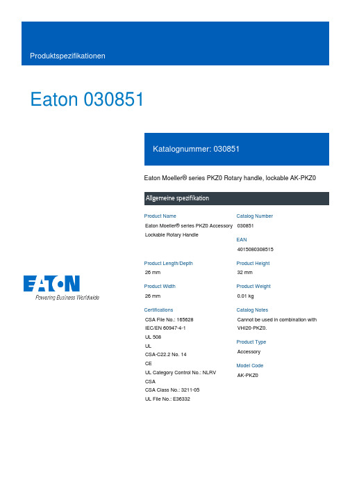
Eaton 030851Eaton Moeller® series PKZ0 Rotary handle, lockable AK-PKZ0Eaton Moeller® series PKZ0 Accessory Lockable Rotary Handle030851401508030851526 mm 32 mm 26 mm 0.01 kg CSA File No.: 165628 IEC/EN 60947-4-1 UL 508 ULCSA-C22.2 No. 14 CEUL Category Control No.: NLRV CSACSA Class No.: 3211-05 UL File No.: E36332Cannot be used in combination with VHI20-PKZ0.Accessory AK-PKZ0Product NameCatalog NumberEANProduct Length/Depth Product Height Product Width Product Weight CertificationsCatalog NotesProduct Type Model CodeBlackLockableFor locking motor-protective circuit-breakers PKZM0, PKZM4 and PKE as a main switch in compliance with EN 60204Lockable in the 0 (Off) position (with padlock)6.35 mm AccessoriesSwitch disconnector P-SOL and PKZ-SOL-25 °C55 °C0 W0 W0 W0 A0 WMeets the product standard's requirements. Meets the product standard's requirements. Meets the product standard's requirements. Meets the product standard's requirements.DA-DC-00004945.pdf DA-DC-00004953.pdf DA-DC-00004892.pdf DA-DC-00004916.pdf DA-DC-00004891.pdf DA-DC-00004889.pdf DA-DC-00004960.pdf DA-DC-00004880.pdf DA-DC-00004917.pdf DA-DC-00004890.pdf DA-DC-00004913.pdf DA-DC-00004918.pdf DA-DC-00004961.pdf DA-DC-00004920.pdf DA-DC-00004950.pdf DA-DC-00004935.pdf DA-DC-00004912.pdf DA-DC-00004911.pdf DA-DC-00004919.pdf DA-DC-00004921.pdfColor Features Functions Locking facility Thickness Product CategorySuitable forUsed withAmbient operating temperature - min Ambient operating temperature - maxEquipment heat dissipation, current-dependent PvidHeat dissipation capacity PdissHeat dissipation per pole, current-dependent PvidRated operational current for specified heat dissipation (In)Static heat dissipation, non-current-dependent Pvs10.2.2 Corrosion resistance10.2.3.1 Verification of thermal stability of enclosures10.2.3.2 Verification of resistance of insulating materials tonormal heat10.2.3.3 Resist. of insul. mat. to abnormal heat/fire by internalelect. effects10.2.4 Resistance to ultra-violet (UV) radiationDeclarations of conformityMeets the product standard's requirements.Does not apply, since the entire switchgear needs to be evaluated.Does not apply, since the entire switchgear needs to be evaluated.Meets the product standard's requirements.Does not apply, since the entire switchgear needs to be evaluated.Meets the product standard's requirements.Does not apply, since the entire switchgear needs to be evaluated.Does not apply, since the entire switchgear needs to be evaluated.Is the panel builder's responsibility.Is the panel builder's responsibility.Is the panel builder's responsibility.Is the panel builder's responsibility.Is the panel builder's responsibility.Not applicable.Is the panel builder's responsibility. The specifications for the switchgear must be observed.Is the panel builder's responsibility. The specifications for the switchgear must be observed.DA-DC-00004885.pdfDA-DC-00004881.pdfDA-DC-00004888.pdfDA-DC-00004910.pdfDA-DC-00004915.pdfDA-DC-00004937.pdfDA-DC-00004887.pdfDA-DC-00004886.pdfDA-DC-00004878.pdfDA-DC-00004952.pdfDA-DC-00004879.pdfDA-CE-ETN.AK-PKZ0WIN-WIN mit Push-in-TechnikProduktübersicht für den MaschinenbauSortimentskatalog Motoren schalten und schützenDA-CS-ak_pkz0DA-CD-ak_pkz0eaton-manual-motor-starters-circuit-breaker-pkzm4-dimensions.eps eaton-manual-motor-starters-pkz0-rotary-handle-dimensions.eps eaton-manual-motor-starters-rotary-handle-pkz0-rotary-handle-3d-drawing.eps10.2.5 Lifting10.2.6 Mechanical impact10.2.7 Inscriptions10.3 Degree of protection of assemblies10.4 Clearances and creepage distances10.5 Protection against electric shock10.6 Incorporation of switching devices and components 10.7 Internal electrical circuits and connections10.8 Connections for external conductors10.9.2 Power-frequency electric strength10.9.3 Impulse withstand voltage10.9.4 Testing of enclosures made of insulating material 10.10 Temperature rise10.11 Short-circuit rating10.12 Electromagnetic compatibility eCAD model Installationsvideos KatalogemCAD model ZeichnungenEaton Konzern plc Eaton-Haus30 Pembroke-Straße Dublin 4, Irland © 2023 Eaton. Alle Rechte vorbehalten. Eaton ist eine eingetrageneMarke.Alle anderen Warenzeichen sindEigentum ihrer jeweiligenBesitzer./socialmediaThe device meets the requirements, provided the information in the instruction leaflet (IL) is observed.10.13 Mechanical function。
ELESA+GANTER中国明星产品GANTER制造GN 300可调手柄

主尺寸 h1 24.5 24.5 24.5 24.5 24.5 24.5 24.5 24.5 24.5 24.5 24.5 31 31 31 36 36 36 36 43 43 43 50.5 50.5 50.5 50.5 50.5 h2 4 4 4 4 4 4 4 4 4 4 4 6.5 6.5 6.5 8 8 8 8 11 11 11 12 12 12 12 12 h3 31 31 31 31 31 31 35 35 35 35 35 45 45 45 55 55 55 55 65 65 65 76 76 76 76 76 h4 3.5 3.5 3.5 3.5 3.5 3.5 3.5 3.5 3.5 3.5 3.5 4 4 4 4 4 4 4 4 4 4 5 5 5 5 5 d1 M3 M4 M5 M6 M4 M5 M6 M6 M8 M8 M10 M10 M12 M12 M14 M16
This product had the following design awards:
安装孔 d2 5 6 5 6 8 8 10 12 12 16 tmin. 7 7 7 9 9 9 9 9 9 9 9 11 11 11 14 14 14 17 17 17 17 22 22 22 22 22
重量 g 15 15 15 15 15 15 33 32 34 34 33 74 76 74 122 118 123 194 178 194 171 305 345 306 298 306
紧固元件
钢质,黑色氧化涂层处理,带用于联接杆体的螺纹孔和有齿元件,以及精制钢固定螺钉和复位弹簧。
应要求可提供以下特殊型号(如订货数量充足)
- 不同颜色杆体 - 镀铬手柄 - 不同螺纹和长度的紧固元件(螺杆)
特征及应用
ELESA+GANTER欧洲原产带旋转手柄的操纵手轮 EWW-XX

按需可有以下附件备选备选 - GN 184型轴向定位垫圈(参见第631页)。 - 如不安装指示器,可用CP.型前盖替代。
特征及应用
此类操纵手轮专门设计用于安装在机器或设备的控制轴上,以及用于叉车及搬运车辆的导向。
人体工程学及设计理念理念
此操纵手轮的外廓线较低,可平装于控制板上,从而将突出部分的体量减至最小。
EWW-XX
带旋转手柄的操纵手轮
ELESA 原创设计
technical informations 材料 玻璃纤维加固聚丙烯基(PP )高科技聚合体。耐溶剂、机油、油脂以及其它化学溶剂。
颜色
黑灰色,亚光饰面。
装配
钢质轮毂,黑色氧化处理,带标准H7铰孔。带聚甲醛基(POM)高科技聚合体制成的尾部法兰及冠状齿轮。黑色氧化处理钢材制成的螺钉及定位销。
ELESA 和 GANTER 依法保留所有权利。复制图纸时请注明出处。
主尺寸 d 5 h2 f 1 l 1 l 2 l 3 l 4 l 5 R
孔Байду номын сангаас d H7 h 20 H
手柄 m R1
重量 g
240 59 30 25.5 79 68.5 6
4 M4 21 13 15 13 23 28.5
24 65 M10 97 810
This product had the following design awards:
旋转手柄
IEL+x型(参见第371页),半刚性热塑性合成橡胶(TPE)制成,硬度40SD,黑色,亚光饰面。手柄处双径体的特殊设计使得操作者在转动手轮 时,可安全握紧,符合人体工程学要求。
可按客户需求提供以下形式的特殊订制(如订货数量足够)
EWW+IEL型操纵手轮还可与重力式指示器联用。
norelem 手轮 DIN 950 产品说明书
定位孔
140 16H7 36 19 39 - - 3
定位孔
160 14H7 36 20 40 - - 3
定位孔
160 16H7 36 20 40 - - 3
定位孔
180 16H7 37 22 43 - - 3
定位孔
180 18H7 37 22 43 - - 3
定位孔
200 18H7 43 24 45 - - 3
定位孔
400 34H7 65 38 63 - - 5
定位孔
500 34H7 79 45 72 - - 5
定位孔
500 40H7 79 45 72 - - 5
带开槽的定位孔 80 10H7 25 16 29 3 11,4 3
带开槽的定位孔 80 12H7 25 16 29 4 13,8 3
带开槽的定位孔 100 10H7 29 17 33 3 11,4 3
固定 手柄 DIN 39 E 型
-
旋转手柄 DIN 98 E型
-
© norelem
1/3
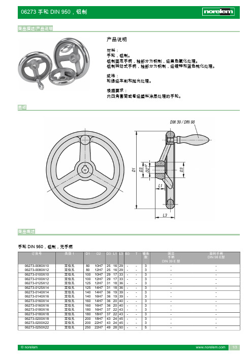
06273 手轮 DIN 950,铝制
商品概述
订货号
06273-0250X26 06273-0315X26 06273-0315X30 06273-0400X30 06273-0400X34 06273-0500X34 06273-0500X40 06273-1080X10 06273-1080X12 06273-1100X10 06273-1100X12 06273-1125X12 06273-1125X14 06273-1140X14 06273-1140X16 06273-1160X14 06273-1160X16 06273-1180X16 06273-1180X18 06273-1200X18 06273-1200X22 06273-1250X22 06273-1250X26 06273-1315X26 06273-1315X30 06273-1400X30 06273-1400X34 06273-1500X34 06273-1500X40 06273-2080X10 06273-2080X12 06273-2100X10 06273-2100X12 06273-2125X12 06273-2125X14 06273-2140X14 06273-2140X16 06273-2160X14 06273-2160X16 06273-2180X16 06273-2180X18 06273-2200X18 06273-2200X22 06273-2250X22 06273-2250X26 06273-2315X26 06273-2315X30 06273-2400X30 06273-2400X34 06273-2500X34 06273-2500X40 06273-3080X10 06273-3080X12 06273-3100X10 06273-3100X12 06273-3125X12 06273-3125X14 06273-3140X14 06273-3140X16 06273-3160X14 06273-3160X16 06273-3180X16 06273-3180X18 06273-3200X18
PS690U系列保护测控装置技术使用说明书V1.3
2009-12-24
2009-12-11 2009-7-27 2008-4-2 修改日期
* 技术支持
电话:(025)83537262
传真:(025)83537201
* 本说明书可能会被修改,请注意核对实际产品与说明书的版本是否相符
* 2010 年 8 月 第 1 版 第 1 次印刷
双功能SG-42SK系列金属手柄拉铃说明书

Dual ActionSG-42SK Series Die-Cast Metal Manual Pull StationsDescriptionThe SG-42SK Series are key-reset, manual pull stationsdesigned to meet the requirements for many applications. They are constructed from a rugged, but lightweight, die-cast metal alloy for increased performance and longevity. This series of stations is available in single action (PULL lever) or dual action (PUSH bar and PULL lever) models.Sigcom SG Series pull stations include a terminal strip that can accommodate wiring from #22 to #14 AWG. Contacts are gold plated to minimize risk of corrosion. All models have been tested by UL and found in compliance with the pull force requirementsof the Americans with Disabilities Act (ADA).OperationThe stations are operated by pulling the handle marked “PULL”on the front of the unit as far down as it will go. At that point, the handle will lock in place and is easily visible from up to 50 feet. The activation handle is reset by opening the station with the key, placing the “PULL” handle to its normal upright position and relocking the station. On the dual action, the “PUSH” bar moves inward allowing the “PULL” handle to be operated by a single hand.Mounting Configurations• Semi-Flush --All models mount on a standard single-gang back-box.• Surface Mount Interior --Use SigCom SGB-32S or the deeper metal back-box SGB-32SD.• Surface Mount Exterior --Use SigCom die cast weatherproof back-box #SG-WP or the deeper back-box SGB-32CD. Includes gasket set, final assembly achieves NEMA 3R rating. Features• Single or Dual Action • Screw Terminal Connections• DC and AC Voltage Contact Ratings • Gold Plated Alarm Contacts • Surface or Weatherproof Back-box• Deeper Back-boxes available to provide more space for wire and/or addressable module.• Optional Station Colors, Labels (See Spectrum Data sheet)MEANYC ApprovedSignal Communications Corporation4 Wheeling Avenue • Woburn, MA 01801 USATel +1-781-933-0998 • Fax +1-781-933-5019Single ActionDualActionDual ActionwithEmergency BarSIGCOM SG-42 Series Manual Pull Stations for FireSPECIFICATIONSListings: UL, ULC, FM, CSFM, MEA Temperature: -400 to 1500F; 400 to 650C, 90% relative humidity @ 1000F; 380C Switch Rating: 2 Amps @ 125 VDC, 2 Amps @ 240 VAC, Screw Terminal Block #22 to #14 gauge wire Pull Station Weight: 1.2 lbs, 0.55 kg Pull Station Dimensions: 4.75”h x 3.25”w x 1.1”d; 12.1 x 8.3 x 2.8 cm Surface-Mount Backbox Dims: Outside: 4.75”h x 3.25 “w x 2.25”d; 12.1 x 8.3 x 5.7 cm Inside Depth: 2.12”; 5.4 cmDeep Surface-Mount Backbox Dims: Outside 4.75”h x 3.25”w x 2.75”d; 12.1 x 8.3 x 7.0 cm Inside Depth 2.62”; 6.6 cm Lock: CAT30 aka “B” keylock is standard (other available, consult factory) Break-Rod: Optional, not required for operation. One break-rod is included with each pull stationORDERING INFORMATIONPull Stations for Fire Alarm Systems - RedSG-42SK1-SC Dual Action, for Fire Alarm, SPST, NO, Red SG-42SK2-SC Single Action, for Fire Alarm, SPST, NO, Red SG-42SK1* Dual Action, for Fire Alarm, SPST, NO, RedSG-42SK2* Single Action, for Fire Alarm, SPST, NO, RedSG-42CXK1-RD Dual Action, for Fire Alarm, DPDT, Red SG-42CXK2-RD Single Action, for Fire Alarm, DPDT, Red SG-42CXK1E-RD Dual Action, with Emergency Push Bar, DPDT, Red* Pull station models available without Sigcom brand for private label - contact Customer Service for details. Back Boxes for Pull Stations – Red SGB-32S Sheet Metal Back Box, Indoor Use, two - 1/2" knockouts, Red SGB-32SD Sheet Metal Back Box, Deep Version, Indoor Use, two - 1/2" knockouts, Red SG-WP Weather Proof Back Box, Outdoor Use, NEMA 3R, one hole 3/4" NPT, Red SG-32CD Weather Proof Back Box, Deep Version, Outdoor Use, NEMA 3R, one hole 3/4" NPT, Red Accessories for Pull Station SG-GR01 Replacement Break-Rods (12 per package) Notes: One (1) break-rod is included with each pull station; Break-rod is not required for operation SG-LOCK-* Alternate lock set (* Consult Factory for options), CAT15, CAT45, CAT60, Hex,Also:• Alternative Colors, Labels - See Sigcom SPECTRUM Series Data Sheet• New York City MEA listed Stations – See Sigcom NYC Stations, SG-33 Series Data Sheet • Marine Rated and Explosion Proof Pull Stations – See Sigcom SGX Series Data SheetSignal Communications Corporation4 Wheeling Avenue • Woburn, MA 01801 USA Tel +1-781-933-0998 • Fax +1-781-933-5019SG-42 Series Data Sheet052318SingleAction。
电子手柄型手抓器 LEHF 型号选择和参数设置说明书

Electric Gripper 2-Finger TypeSeries LEHFModel SelectionSelection ProcedureStep 1Check the gripping force.27C o u r t e s y o f C M A /F l o d y n e /H y d r a d y n e ŀ M o t i o n C o n t r o l ŀ H y d r a u l i c ŀ P n e u m a t i c ŀ E l e c t r i c a l ŀ M e c h a n i c a l ŀ (800) 426-5480 ŀ w w w .c m a f h .c o mCheck the gripping force: Series LEHF# Indication of gripping forceGripping force shown in the graphsbelow is expressed as “F”, which is thegripping force of one finger, when bothfingers and attachments are in fullcontact with the workpiece as shown inthe figure below.#Set the workpiece gripping point “L” sothat it is within the range shown in thefigure below.Pushing force is one of the values of step data that is input into the controller.Selection ProcedureModel Selection SeriesLEHF28 CourtesyofCMA/Flodyne/HydradyneŀMotionControlŀHydraulicŀPneumaticŀElectricalŀMechanicalŀ(8)426-548ŀwww.cmafh.comSelection ProcedureCheck the gripping point and overhang: Series LEHF# Decide the gripping position of the workpiece so that the amount of overhang “H” stays within the range shown in the figure below.# If the gripping position is out of the limit, it may shorten the life of the electric gripper.External Gripping StateInternal Gripping StatePushing force is one of the values of step data that is input into the controller.Series LEHF29C o u r t e s y o f C M A /F l o d y n e /H y d r a d y n e ŀ M o t i o n C o n t r o l ŀ H y d r a u l i c ŀ P n e u m a t i c ŀ E l e c t r i c a l ŀ M e c h a n i c a l ŀ (800) 426-5480 ŀ w w w .c m a f h .c o mNote) Values for load in the table indicate static values.Check the external force on fingers: Series LEHFFv: Allowable vertical loadMp: Pitch momentMr: Roll momentMy: Yaw momentModel Selection SeriesLEHF30C o u r t e s y o f C M A /F l o d y n e /H y d r a d y n e ŀ M o t i o n C o n t r o l ŀ H y d r a u l i c ŀ P n e u m a t i c ŀ E l e c t r i c a l ŀ M e c h a n i c a l ŀ (800) 426-5480 ŀ w w w .c m a f h .c o mConfirm that the combination of the controller/driver and the actuator is correct.The actuator and controller/driver are sold as a package.<Check the following before use.>: Check the actuator label for model number. This matches the controller/driver.@ Check Parallel I/O configuration matches (NPN or PNP).:@LEHF Refer to the operation manual for using the products. Please download it via our website, How to OrderElectric Gripper 2-Finger TypeLEHF10, 20, 32, 40Series LEHFRoHS®' 2-finger type 31C o u r t e s y o f C M A /F l o d y n e /H y d r a d y n e ŀ M o t i o n C o n t r o l ŀ H y d r a u l i c ŀ P n e u m a t i c ŀ E l e c t r i c a l ŀ M e c h a n i c a l ŀ (800) 426-5480 ŀ w w w .c m a f h .c o m1DIN rail is not included. Order it separately.(Refer to page 56.)Refer to the specifications Note 3) on page 23.parts. For using on moving parts, select the robotic cable.1 When “Without controller/driver” is selected for controller/driver types, I/O cable cannot be selected. Refer to page 61 (For LECP6), page 73 (For LECP1) or page 80 (For LECPA) if I/O cable is required.2 When “Pulse input type” is selected for controller/driver types, pulse input usable only with differential. Only 1.5 m cablesusable with open collector.Electric Gripper 2-Finger Type SeriesLEHFcompatible motors, refer to the compatible controllers/driver below.LECP6Value (Step data) input Standard controllerLECP1Capable of setting up operation (step data)LECPAOperation by pulse signalsC o u r t e s y o f C M A /F l o d y n e /H y d r a d y n e ŀ M o t i o n C o n t r o l ŀ H y d r a u l i c ŀ P n e u m a t i c ŀ E l e c t r i c a l ŀ M e c h a n i c a l ŀ (800) 426-5480 ŀ w w w .c m a f h .c o mMountingdirectionSpecificationsHow to MountNote 1) Gripping force should be from 10 to 20 times the workpiece weight. Positioning force should be 150% whenreleasing the workpiece. Gripping force accuracy should be o 30% (F.S.) for LEHF10, o 25% (F.S.) for LEHF20 and o 20% (F.S.) for LEHF32/40.Note 2) Pushing speed should be set within the range during pushing (gripping) operation. Otherwise, it may cause malfunction.The opening/closing speed and pushing speed are for both fingers. The speed for one finger is half this value.Note 3) The speed and force may change depending on the cable length, load and mounting conditions.Furthermore, if the cable length exceeds 5 m, then it will decrease by up to 10% for each 5 m. (At 15 m: Reduced by up to 20%)Note 4) R epeatability means the variation of the gripping position (workpiece position) when the grippingoperation is repeatedly performed by the same sequence for the same workpiece.Note 5) Repeated length measurement accuracy means dispersion (value on the controller monitor) when theworkpiece is repeatedly held in the same position.Note 6) There will be no influence of backlash during pushing (gripping) operation. Make the stroke longer forthe amount of backlash when opening.Note 7) Impact resistance: No malfunction occurred when the gripper was tested with a drop tester in both anaxial direction and a perpendicular direction to the lead screw. (Test was performed with the gripper in the initial state.)Vibration resistance: No malfunction occurred in a test ranging between 45 to 2000 Hz. Test was performed in both an axial direction and a perpendicular direction to the lead screw. (Test was performed with the gripper in the initial state.)Note 8) The power consumption (including the controller) is for when the gripper is operating.The standby power consumption when operating is for when the gripper is stopped in the set position during operation, including the energy saving mode when gripping.Note 9) The maximum instantaneous power consumption (including the controller) is for when the gripper isoperating. This value can be used for the selection of the power supply.a) When using the thread on the bodyb) When using the thread on the mounting plate c) When using the thread on the back of the bodySeries LEHF33C o u r t e s y o f C M A /F l o d y n e /H y d r a d y n e ŀ M o t i o n C o n t r o l ŀ H y d r a u l i c ŀ P n e u m a t i c ŀ E l e c t r i c a l ŀ M e c h a n i c a l ŀ (800) 426-5480 ŀ w w w .c m a f h .c o mConstructionSeries LEHFElectric Gripper 2-Finger Type SeriesLEHF34C o u r t e s y o f C M A /F l o d y n e /H y d r a d y n e ŀ M o t i o n C o n t r o l ŀ H y d r a u l i c ŀ P n e u m a t i c ŀ E l e c t r i c a l ŀ M e c h a n i c a l ŀ (800) 426-5480 ŀ w w w .c m a f h .c o my 290(Motor cable entry:y 230(Motor cable entry:on the fingers does not interfere with the workpieces and facilities around the fingers.y 280(Motor cable entry:y 230(Motor cable entry:Note) Range within which the fingers can move when itreturns to origin. Make sure a workpiece mounted on the fingers does not interfere with the workpieces and facilities around the fingers.DimensionsLEHF10K2-16: BasicLEHF10K2-32: Long StrokeSeries LEHF35C o u r t e s y o f C M A /F l o d y n e /H y d r a d y n e ŀ M o t i o n C o n t r o l ŀ H y d r a u l i c ŀ P n e u m a t i c ŀ E l e c t r i c a l ŀ M e c h a n i c a l ŀ (800) 426-5480 ŀ w w w .c m a f h .c o my 270(Motor cable entry:y 230(Motor cable entry:a workpiece mounted on the fingers does not interfere with theworkpieces and facilities around the fingers.y 240(Motor cable entry:y 230(Motor cable entry:Mountingreturns to origin. Make surethe fingers does not interfere with theworkpieces and facilities around the fingers.DimensionsLEHF20K2-24: BasicLEHF20K2-48: Long StrokeElectric Gripper 2-Finger Type SeriesLEHF36C o u r t e s y o f C M A /F l o d y n e /H y d r a d y n e ŀ M o t i o n C o n t r o l ŀ H y d r a u l i c ŀ P n e u m a t i c ŀ E l e c t r i c a l ŀ M e c h a n i c a l ŀ (800) 426-5480 ŀ w w w .c m a f h .c o mit returns to origin.Make sure a workpiece mounted on the fingers does not interfere with the workpieces and facilities around thefingers.on the fingers does not interfere with the workpieces and facilities around the fingers.y 240(Motor cable entry:y 220(Motor cable entry:y 190(Motor cable entry:y 220(Motor cable entry:MountingDimensionsLEHF32K2-32: BasicSeries LEHF37C o u r t e s y o f C M A /F l o d y n e /H y d r a d y n e ŀ M o t i o n C o n t r o l ŀ H y d r a u l i c ŀ P n e u m a t i c ŀ E l e c t r i c a l ŀ M e c h a n i c a l ŀ (800) 426-5480 ŀ w w w .c m a f h .c o mon the fingers does not interfere with the workpieces and facilities around the fingers.returns to origin. Make sure a workpiece mounted on the fingers does not interfere with theworkpieces and facilities around the fingers.y 240(Motor cable entry:y 210(Motor cable entry:LEHF40K2-80: Long Strokey 180(Motor cable entry:y 210(Motor cable entry:DimensionsLEHF40K2-40: BasicElectric Gripper 2-Finger Type SeriesLEHF38C o u r t e s y o f C M A /F l o d y n e /H y d r a d y n e ŀ M o t i o n C o n t r o l ŀ H y d r a u l i c ŀ P n e u m a t i c ŀ E l e c t r i c a l ŀ M e c h a n i c a l ŀ (800) 426-5480 ŀ w w w .c m a f h .c o m。
- 1、下载文档前请自行甄别文档内容的完整性,平台不提供额外的编辑、内容补充、找答案等附加服务。
- 2、"仅部分预览"的文档,不可在线预览部分如存在完整性等问题,可反馈申请退款(可完整预览的文档不适用该条件!)。
- 3、如文档侵犯您的权益,请联系客服反馈,我们会尽快为您处理(人工客服工作时间:9:00-18:30)。
手柄
GN 565
technical informations
铝制,椭圆截面棒材。
- BL型:铝本色,光亮饰面。
- SW型:RAL 9005黑色,亚光饰面,环氧树脂涂层。
- EL型:阳极氧化处理,本色,亚光饰面。
- RS型:RAL 3000红色环氧树脂涂层。
-SR型:RAL 9006银色,亚光饰面,环氧树脂涂层。
螺纹盲孔。
材料
安装
可按需提供以下特殊型号(如订货数量充足)
不同长度的订制柄身。
特征及应用
U形机柜手柄GN 565是由铝制棒材挤压成型的。
该产品的特点为坚固,以及其符合人体工学的外形。
该产品的制造工艺 (折弯)允许以相对较少的起订量,生产特殊长度的定制型号。
标准件主尺寸安装孔重量
型号b l ±0.25a h r d t min.g GN 565-20-100-BL20100134913M61087
GN 565-20-100-SW20100134913M61087
GN 565-20-100-SWU20100134913M61087
GN 565-20-100-EL20100134913M61087
GN 565-20-100-RS20100134913M61087
GN 565-20-100-SR20100134913M61087
GN 565-20-112-BL20112134913M61097
GN 565-20-112-SW20112134913M61097
GN 565-20-112-SWU20112134913M61097
GN 565-20-112-EL20112134913M61097
GN 565-20-112-RS20112134913M61097
GN 565-20-112-SR20112134913M61097
GN 565-20-117-BL20117134913M610100
GN 565-20-117-SW20117134913M610100
GN 565-20-117-SWU20117134913M610100
GN 565-20-117-EL20117134913M610100
GN 565-20-117-RS20117134913M610100
GN 565-20-117-SR20117134913M610100
GN 565-20-120*-BL20120134913M610105
GN 565-20-120*-SW20120134913M610105
GN 565-20-120*-SWU 20120134913M610105
GN 565-20-120*-EL20120134913M610105
GN 565-20-120*-RS20120134913M610105
GN 565-20-120*-SR20120134913M610105
GN 565-20-128-BL20128135113M610107
GN 565-20-128-SW20128135113M610107
GN 565-20-128-SWU 20128135113M610107
GN 565-20-128-EL20128135113M610107
GN 565-20-128-RS20128135113M610107
GN 565-20-128-SR20128135113M610107
GN 565-20-160-BL20160135113M610127
GN 565-20-160-SW20160135113M610127
GN 565-20-160-SWU 20160135113M610127
GN 565-20-160-EL20160135113M610127
GN 565-20-160-RS20160135113M610127 GN 565-20-160-SR20160135113M610127 GN 565-20-180*-BL 20180135113M610138 GN 565-20-180*-SW20180135113M610138 GN 565-20-180*-SWU20180135113M610138 GN 565-20-180*-EL20180135113M610138 GN 565-20-180*-RS20180135113M610138 GN 565-20-180*-SR20180135113M610138 GN 565-20-200-BL20200135113M610150 GN 565-20-200-SW20200135113M610150 GN 565-20-200-SWU20200135113M610150 GN 565-20-200-EL20200135113M610150 GN 565-20-200-RS20200135113M610150 GN 565-20-200-SR20200135113M610150 GN 565-20-235*-BL 20235135113M610172 GN 565-20-235*-SW20235135113M610172 GN 565-20-235*-SWU20235135113M610172 GN 565-20-235*-EL 20235135113M610172 GN 565-20-235*-SR20235135113M610172 GN 565-20-235*-RS20235135113M610172 GN 565-26-112-BL26112175517M812160 GN 565-26-112-SW26112175517M812160 GN 565-26-112-SWU26112175517M812160 GN 565-26-112-EL26112175517M812160 GN 565-26-112-RS26112175517M812160 GN 565-26-112-SR26112175517M812160 GN 565-26-117-BL26117175517M812166 GN 565-26-117-SW26117175517M812166 GN 565-26-117-SWU26117175517M812166 GN 565-26-117-EL26117175517M812166 GN 565-26-117-RS26117175517M812166 GN 565-26-117-SR26117175517M812166 GN 565-26-120-BL26120175517M812170 GN 565-26-120-SW26120175517M812170 GN 565-26-120-SWU 26120175517M812170 GN 565-26-120-EL26120175517M812170 GN 565-26-120-RS26120175517M812170 GN 565-26-120-SR26120175517M812170 GN 565-26-125-BL26125175517M812178 GN 565-26-125-SW26125175517M812178 GN 565-26-125-SWU26125175517M812178 GN 565-26-125-EL26125175517M812178 GN 565-26-125-RS26125175517M812178 GN 565-26-125-SR26125175517M812178 GN 565-26-128-BL26128175517M812183。