A C-band gyro-TWT
MOTOTRBO 专业数字两路无线电重复器 2 加速性能说明书

MOTOTRBO™PROFESSIONAL DIGITAL TWO-WAY RADIO REPEATERS2ACCELERATE PERFORMANCEMOTOTRBO ™ pROfESSIOnAl DIgITAl TWO-WAy RADIO SySTEM ThE fuTuRE Of TWO-WAy RADIO,employees and lower operating costs for your business.Motorola is a company of fi rsts with a rich heritage of innovation. We continue to invent what’s next connecting people, delivering mobility and making technology personal. Versatile and powerful,MOTOTRBO combines the best in two-way radio functionality with digital technology, making it the ideal communication solution for your business. You get enhanced features, increased capacity, integrated data applications, exceptional voice quality and extended battery performance. This means more productiveThE DIgITAl DIffEREncETwo-way radio has been a successful analogue communication solution for generations, and it proves itself every day in countless deployments around the world.But in today’s technologically advanced environment, a new platform is possible, a digital platform that breaks through to new levels of performance and productivity.In the same way digital technology has transformed other media, it is now revolutionising the way mobile professionals communicate. The time to take advantage of digital two-way radio technology is now.TAkE ADvAnTAgE Of DIgITAlDigital two-way radios offer several advantages over analogue solutions, to name a few:• C learer audio to help assure messages are understood without background noise and static• I ntegrated data applications such as text messaging, GPS-based location tracking, work order ticket management and much more • 40% longer battery life for extended work shifts• I ncreased capacity – twice the number of users for the price of one frequency licenseTDMA – ThE BEST chOIcEThere are two primary digital radio technologies: Time-Division Multiple-Access (TDMA) and Frequency-DivisionMultiple-Access (FDMA).While both digital technologies provide significant benefits over analogue, TDMA is the best choice.TDMA technology delivers advantages over fDMA• D ouble your capacity per channel with less than half the infrastructure per channelT DMA divides your existing channels into two time slots enabling you to double the number of users on your system or utilise data applications. A second call does not require a second repeater, resulting in lower costs for you, as you do not need to purchase, install and maintain additional infrastructure equipment.• D ouble your capacity without the hassleTDMA provides two time slots on your existing licensed channels, doubling your capacity. There is no increased risk of interference, and there is no need for new licenses, simply amend your existing licenses to specify digital. Compatibility with all legacy radios working in 12.5 kHz analogue channels is also maintained by TDMA.• L onger battery lifeTDMA uses only half of the transmitter’s capacity, resulting in longer battery life. During long work shifts or where productivity enhancing data applications place an increased power demand on the radio, this extended battery life is invaluable.• A dvanced featuresT DMA enables smart control features like “transmit interrupt” that makes it possible to interrupt lower priority communication so critical instructions can be delivered exactly when they’re needed. And to help you maximise your infrastructure investment, TDMA can transmit voice and data on the same channel.34MOTOTRBO offers a robust, standards-based solution that can be tailored to meet your unique coverage and feature needs. This versatile portfolio provides a complete system of portable radios, mobile radios, repeaters, accessories, data applications, and services, a comprehensive communication solution for your business. MOTOTRBO: unIQuE MOTOTRBO™SySTEM BEnEfITS fOR EnhAncED pRODucTIvITy• I ntegrates voice and data into one device to increase your operational effi ciency and support integrated applications including MOTOTRBO Text Messaging Services. Also features an integrated GPS module for use with third-party location-tracking applications.• U ses Time-Division Multiple-Access (TDMA) digital technology to provide twice the calling capacity (as compared to analogue or FDMA radios) for the price of one frequency license. A second call doesn’t require a second repeater, saving you equipment costs.• In digital mode, provides clearer voice communications throughout the coverage area, as compared to analogue radios, rejecting static and noise.• O ffers enhanced battery life. MOTOTRBO digital two-way portable radios can operate up to 40 percent longer between recharges compared to typical analogue radios.• P rovides easy migration from analogue to digital with the ability to operate in both analogue and digital modes.• E nables additional functionality including dispatch data, enhanced call signaling, basic and enhanced privacy-scrambling and option board expandability.• F eatures the transmit interrupt suite - voice interrupt, remote voice dekey, emergency voice interrupt or data over voice interrupt - to help prioritise critical communication exactly when needed.5MOTOTRBO InTEgRATED DATA EnABlES ADvAncED ApplIcATIOnSOnE DEvIcE fOR vOIcE AnD DATAIn addition to voice, MOTOTRBO supports text messaging, GPS location tracking capability, and custom applications from Motorola’s Professional Radio Application Partner Programme such as telephony, dispatch, work order ticket solutions and much more. MOTOTRBO keeps your employees connected to the information they need to be more effi cient, with the convenience of one device.cOnvEnIEnT AnD DIScRETE MOTOTRBO TEXT MESSAgIngText messaging enables your employees to quickly and easily share information when voice communication isn’t practical. It is ideal in loud environments, for delivering messages that don’t need an immediate response, or when voice communication could be disrupting to guests, students, customers, or patients.MOTOTRBO text messaging communicates between radios, radios and dispatch systems, and even radios to any email capable device.TRAck vEhIclES AnD pEOplE WITh InTEgRATED gpSEvery MOTOTRBO radio has an integrated GPS module to use for tracking people outside your facility, vehicles or other remote assets operating in your coverage area. Unlike other GPS capable radios, MOTOTRBO’s module is integrated into the handset so there is no clumsy additional equipment to attach, carry or maintain.This enables you to better manage your mobile work force and quickly respond to incidents by locating the nearest employee and dispatching them to the scene. It also makes it easier to manage your fl eet so you can make deliveries and drive routes more effi ciently. For utility crews, taxi services, the hospitality industry, and countless other industries, the ability to see where your vehicles and employees are located with just a glance is invaluable. Your employees will be far more effi cient and your customer service can improve signifi cantly.cuSTOM DATA ApplIcATIOnS WITh MOTOROlA’S pROfESSIOnAl RADIOApplIcATIOn pARTnER pROgRAMMEMOTOTRBO which can accommodate custom data applications that adapt the radios to support your specifi c business tasks. You can, for example, work with third-party developers or your own IT staff to extend the functionality of MOTOTRBO using Motorola’s Professional Radio Application Partner Programme.With this development tool you can create unique applications such as a program to help you manage your work order tickets,to integrate your dispatch and billing systems, to link your MOTOTRBO radios to your telephone system, or to connect to email. MOTOTRBO is a powerful tool for communication with the fl exibility to adapt to your work force, your customers and your business.678ADDITIOnAl fEATuRES• A utomated battery back-up capability• Expanded coverage across multiple sites with IP Site Connect*• I ncreased voice and data capacity with Capacity Plus single-site trunking*• D ynamic mixed mode capability allows for automatic switching between analogue and digital mode• R epeater diagnostic and control software provides remote or local site monitoringMOTOTRBO ™ SySTEM cOMpOnEnTS AnD BEnEfITSREpEATER STAnDARD pAckAgE• Repeater • AC Power Cord• Two-year Standard Warranty12561 1.2 S3 I4O 5l both channel slots.6R ack- or wall-mountable, compatible with desktop housing as well.7Sturdy handles make installation and handling easier.*Digital mode only9vhf/uhfDR 3000MOTOTRBO REpEATER SpEcIfIcATIOnSSpecifi cations subject to change without notice. All specifi cations shown are typical. Repeater meets applicable regulatory requirements.Channel Capacity16Typical RF OutputLow Power UHF1 and VHFHigh Power UHF2 (450-512 MHz)High Power UHF2 (512-527 MHz)High Power UHF1High Power VHF 1-25 W 1-40 W 1-25 W 25-40 W 25-45 WFrequency136-174 MHz (VHF)403-470 MHz (UHF1)450-527 MHz (UHF2)Dimensions (HxWxL)132.6 x 482.6 x 296.5 mm Weight14 kgVoltage Requirements 100-240 V AC (13.6 V DC)Current Drain:Standby>0.2A (100 V AC)>0.1A (240 V AC)>1.5A (typical) (13.4 V DC)Transmit Low Power High Power>2.0A (100 VAC)>1.0A (240 VAC)>9.0A (typical) (13.4 VDC)>2.5A (100 V AC)>1.25A (240 V AC)>12.0A (typical) (13.4 V DC)Operating Temperature Range -30°C to +60°C Max Duty Cycle 100%Digital ProtocolETSI-TS 102 361-1, 2 & 3Frequency136-174 MHz (VHF)403-470 MHz (UHF1)450-527 MHz (UHF2)Channel Spacing 12.5 kHz / 20 kHz / 25 kHz Frequency Stability( -30° C, +60° C, +25° C) +/- 0.5 ppmAnalogue Sensitivity0.30 uV (12 dB SINAD)0.22 uV (typical) (12 dB SINAD)0.4 uV (20 dB SINAD)Digital Sensitivity 5% BER: 0.3 uV Intermodulation70 dBAdjacent Channel Selectivity ************70 dB @ 20/25 kHz Spurious Rejection70 dB Audio Distortion @ Rated Audio 3% (typical)Hum and Noise *************-45 dB @ 20/25 kHz Audio Response+1, -3 dB Conducted Spurious Emission-57 dBm < 1GHzTransmitterFrequency136-174 MHz (VHF)403-470 MHz (UHF1)450-527 MHz (UHF2)Channel Spacing 12.5 kHz / 20 kHz / 25 kHz Frequency Stability( -30° C, +60° C, +25° C)+/- 0.5 ppmPower OutputLow Power UHF1 and VHFHigh Power UHF2 (450-512 MHz)High Power UHF2 (512-527 MHz) High Power UHF1High Power VHF 1-25 W 1-40 W 1-25 W 25-40 W 25-45 WModulation Limiting+/***************+/- 4 kHz @ 20 kHz +/- 5.0 kHz @ 25 kHz FM Hum and Noise*************-45 dB @ 20/25 kHz Conducted / Radiated Emission -36 dBm < 1 GHz -30 dBm > 1 GHz Adjacent Channel Power *************-70 dB @ 20/25 kHz Audio Response +1, -3 dB Audio Distortion 3%Digital Vocoder TypeAMBE+210ADDITIOnAl fEATuRES• C onvenient access to station ports, shortening installation and maintenance time• 12.5 or 25 kHz programmable channel spacing • 6.25e Compliant• I ntegrated 100W Power Amplifier and AC/DC Power Supply minimises cabling, rack space, expense, and overall complexity • Software based design simplifies feature upgrades • Power supply functions over a wide range of voltages• S upports MOTOTRBO Capacity Plus single site trunking without a separate hardware controller*• Expanded coverage across multiple sites with IP Site Connect*• R epeater diagnostic and control software provides remote or local site monitoring• Automated battery back up (charger sold separately)• Restriction of Hazardous Substances (RoHS) compliantMOTOTRBO ™ SySTEM cOMpOnEnTS AnD BEnEfITSBASE STATIOn / REpEATER STAnDARD pAckAgE• MTR3000 Base Station / Repeater • AC Power Cord• MOTOTRBO Repeater Installation Guide • Two-year Standard Warranty379854/ REpEATER1 12 345 lEDs clearly indicate transmit and receive modes and overall station status 6 Rack-or-cabinet mountable7 front access speaker port for serviceability ease 8 front access microphone port for routine service 9Standard uSB port for station configuration*Digital mode onlyMTR3000 BASE STATIOn / REpEATER SpEcIfIcATIOnSSpecifications subject to change without notice. All specifications shown are typical.Repeater meets applicable regulatory requirements.11MOTOROLA and the Stylised M Logo are registered in the U.S. Patent and Trademark Office. All other product or service names are the property of their registered owners. © Motorola, Inc. 2010Repeater-BROCH_UK (04/10)Motorola, Ltd. Jays Close, Viables Industrial Estate,Basingstoke, Hampshire, RG22 4PD, UK/mototrboFor more information please contact your local Motorola Authorised Dealer or DistributorSuBScRIBER REpAIRManaging the in-house repair and maintenance of your subscriber radios takes a dedicated staff of technicians, as well as anongoing investment in diagnostic equipment, repair tools, and the technical training to keep up to speed on the latest technology. Motorola has made that investment and can help you easily and cost effectively keep your radios in top operating condition to ensure optimal efficiency and productivity.Our subscriber repair service offering allows you to budget for your repairs, preventing unexpected service and maintenance costs. Extended Care Option repairs receive priority service and meet committed cycle times from our European Radio Service Centre.• Extended care Option (EcO):Extended Care Option is a post-warranty service offering that extends the service coverage of Motorola portable or mobile subscriber radios. ECO can be purchased as an option to new radio purchases and is available to extend service coverage for up to five years.• EcO Service Benefits:With our proven repair capability, you can be sure your equipment is expertly repaired and back in your end users’ hands quickly. Using the latest tools and with strict adherence to Motorola engineering procedures, our European Radio Support Center’s expert technicians diagnose and repair units to original manufacturing specifications. With the Extended Care Option, you receive:- Fast and committed turnaround times - Predictable budgets - Cost effective repairs - Peace of mindMOTOTRBO ™ SERvIcE OffERIngS。
Arista C-230 Wi-Fi 6 AP 产品说明书

Data Sheet AccessC-230 provides Wi-Fi networks that require less time and resources to deploy and maintain compared to traditional devices, resulting in significant cost savings.•Plug and play provisioning using either Cloud or On-premise deployments - Arista Access Points take less than two minutes to activate and configure after connecting to the cloud•Support for up to eight individual SSIDs per radio providing maximum flexibility in network design•Network controls like NAT, Firewall and QoS implemented at the Access Point, ensuring faster and more reliable networks •Continuous scanning of all 2.4 GHz and 5 GHz channels by a dedicated 2x2 third radio provides a dynamic, 360-degree view of the RF environment to assist in RF optimization and client handling•Network availability and performance assurance using the third radio as a client to conduct on-demand and scheduled connectivity and performance tests•Smart steering addresses sticky client issues by automatically pushing clients with low data rates to a better access point•Band steering manages channel occupancy, pushing clients to the 5 GHz channel for optimal throughput•Smart load balancing distributes load evenly across neighbouring APs to optimize the use of network resources•Arista Wi-Fi’s distributed data plane architecture continues to serve users and secure the network even if connection with the management plane is interrupted•Interference avoidance from LTE/3G small/macro cells in commonly used TDD/FDD frequency bandsSecurityC-230 offers complete visibility and control of the wireless airspace ensuring network integrity while actively protecting users without manual intervention.•C-230 is equipped with industry leading fully integrated wireless intrusion prevention capabilities•Multifunction third radio provides uninterrupted spectrum scanning or client emulation for always on security coverage alongside dedicated 2.4G/5G client radios.•Arista’s patented Marker Packets TM help accurately detect rogue access points on any network while minimizing false positives•Third radio used as a dedicated security sensor for 24x7x365 scanning and automated over-the-air (OTA) prevention•Deterministic rogue AP detection and prevention by monitoring all WiFi and non-WiFi VLANs.•Over-the-air and on-the-wire prevention techniques assure automatic and reliable threat prevention to keep unauthorized clients and rogue APs off the network without impacting authorized connections.•Access Points autonomously scan for wireless threats and enforce security policy even if disconnected from the cloud management plane•VLAN monitoring enables a virtual connection to non-WiFi networks for complete network rogue detection and preventionAnalyticsThe C-230 collects telemetry on connected and unconnected WiFi clients and supports immersive guest network experiences that help Arista’s customers develop and reinforce the relationship with their end customers.•Reports of customer footfall, demographic, loyalty and other analytics provide insightful and actionable information.•Supports proximity marketing programs that trigger when certain devices are present, which includes automatic messaging vis MMSin-browser notifications and real time notifications sent to 3rd party systems that alert to the presence of enrolled devices.Data SheetWiFi SpecificationsIEEE 802.11a/n/ac/axFrequency BandScanning TransmissionAll regions USA & Canada (FCC/IC)Europe (ETSI) 5GHz Band4.92 ~5.08 GHz5.15 ~ 5.25 GHz 5.25 ~ 5.35 GHz 5.47~ 5.725 GHz 5.725~ 5.825 GHz5.15 ~ 5.25 GHz 5.25 ~ 5.35 GHz 5.725~ 5.825 GHz5.15 ~ 5.25 GHz 5.25 ~ 5.35 GHz 5.47~ 5.725 GHzDynamic Frequency Selection DFS and DFS2 Modulation Type OFDM / OFDMA Peak Data Rates Up to 2.4 GbpsAntennaIntegrated modular high efficiency PIFA antenna x4 (peak gain: 3.9 dBi)Operational Specifications Input Power12V DC (5.5mm overall diameter/2.1mm center pin hole) PoE+ power•••Full function U SB off Max EIRP 1 of 31.5 dBm at 5GHz, 28 dBm at 2.4GHz 5 GHz limited to 2x2 operation2 access radios; one 2x2:2 2.4GHz and one 4x4:4 5GHz radio for simultaneous dual band access.1 multi-function 2x2 radio for continuous WIPS and client connectivity tests Number of RadiosMU-MIMO4X4 on 5GHz radio and 2X2 on 2.4GHz radioNumber of Spatial Streams 4 for 5GHz radios, 2 for 2.4GHz radio, 2 for multipurpose radio Maximum EIRP35dBm on 5GHz radio (max) and 31dBm on 2.4GHz radio (max)1; 80+80MHz Non-Contiguous Channel Bonding No Bandwidth AgilityYes3G/4G Macro and Small Cells InterferenceMitigation YesFrequency Bands 22.4-2.4835 GHz, 4.9-5.0GHz, 5.15-5.25 GHz; (UNII-1), 5.25-5.35 GHz, 5.47-5.6 GHz, 5.650-5.725 GHz (UNII-2), 5.725-5.85 GHz (UNII-3)Dynamic Frequency SelectionSupported in compliance to all latest amendments from FCC, CE, IC, TELEC, KCC, NCC and ANZ regarding certifications.Max Clients Supported 1024 (512 clients per radio) (dependent upon use cases)1 Max EIRP will be restricted to Country/Regulatory domain limits 2The frequency ranges are restricted to Country/Regulatory domain limits•PoEData SheetIEEE802.11b/g/n/axFrequency BandScanning TransmissionAll regions USA & Canada (FCC/IC) Europe (ETSI)2.4GHz Band2400 ~ 2483.5 MHz 2400 ~ 2473.5 MHz 2400 ~ 2483.5 MHz Modulation Type DSSS / OFDM / OFDMAPeak Data Rates Up to 0.6 GbpsAntenna Integrated modular high efficiency PIFA antenna x2 (peak gain: 3 dBi)Receive Sensitivity5GHz 2.4GHzMode Rate Sensitivit y (dBm)802.11a 6 Mbps-93 54 Mbps-7611n_HT20MCS 0-94 MCS 7-7611n_HT40MCS 0-91 MCS 7-7311ac_VHT20MCS 0-94 MCS 8-7211ac_VHT40MCS 0-91 MCS 9-6811ac_VHT80MCS 0-88 MCS 9-6511ax_HE20MCS 0-94 MCS 11-6511ax_HE40MCS 0-91 MCS 11-6211ax_HE80MCS 0-88MCS 11-59Mode Rate Sensitivit y (dBm)802.11b1 Mbps-9811 Mbps-90802.11g6 Mbps-9354 Mbps-7711n_HT20MCS 0-94MCS 7-7611n_HT40MCS 0-91MCS 7-7311ax_HE20MCS 0-94MCS 11-6511ax_HE40MCS 0-91MCS 11-62Data Sheet Maximum EIRP5GHz 2.4GHzMode Rate Power(dBm)802.11a6 ~ 18 Mbps 35 24 ~ 54 Mbps 35802.11n_HT20 MCS 0 ~ 4 35 MCS 5 ~ 7 35802.11n_HT40 MCS 0 ~ 4 35 MCS 5 ~ 7 35802.11ac_VHT20 MCS 0 ~ 4 35 MCS 5 ~ 7 35 MCS 8 ~ 9 35802.11ac_VHT40 MCS 0 ~ 4 35 MCS 5 ~ 7 35 MCS 8 ~ 9 34802.11ac_VHT80 MCS 0 ~ 4 35 MCS 5 ~ 7 35 MCS 8 ~ 9 34802.11ax_HE20MCS 0 ~ 4 35 MCS 5 ~ 7 35 MCS 8 ~ 9 35 MCS 10- 11 34802.11ax_HE40MCS 0 ~ 4 35 MCS 5 ~ 7 35 MCS 8 ~ 9 34 MCS 10- 11 34802.11ax_HE80MCS 0 ~ 4 35MCS 5 ~ 7 34MCS 8 ~ 9 34MCS 10 ~ 11 34Mode!Rate!Power(dBm)!802.11b 1 ~ 11 Mbps 31802.11g6 ~ 18 Mbps 3124 ~ 54 Mbps 31802.11n_HT20MCS 0 ~ 4 31MCS 5 ~ 7 31802.11n_HT40MCS 0 ~ 4 31MCS 5 ~ 7 31802.11ax_HE20MCS 0 ~ 4 31MCS 5 ~ 7 29MCS 8 ~ 9 29MCS 10 ~ 11 29802.11ax_HE40MCS 0 ~ 4 31MCS 5 ~ 7 29MCS 8 ~ 9 28MCS 10 ~ 11 28Pe ak Gain:3.9dBiData SheetRegulatory Specifications RF a nd ElectromagneticCountry CertificationUSA FCC Part 15.247, 15.407 Canada ICEuropeCE EN300.328, EN301.893, EN301 489-1, EN55032, EN62311Countries covered under Europe certification: Austria, Belgium, Bulgaria, Croatia, Cyprus, Czechia, Denmark, Estonia, Finland, France, Germany, Greece, Hungary, Ireland, Italy,Latvia, Lithuania, Luxembourg, Malta, the Netherlands, Poland, Portugal, Romania, Slovakia, Slovenia, Spain, Sweden, United Kingdom.*For complete country certification records, please visit the site: https:///en/support/product-certificateSafetyCountryCertificationUSA UL 60950 UL 2043 CanadacUL 60950European Union (EU) EN 60950, EN 62368-1 TaiwanCNS14336-1Ordering Information Access PointPart NumberDescriptionAP-C230 C-230 4x4 tri radio 802.11ax (WiFi 6) access point with internal antennas AP-C230-SS-5Y C-230 AP with 5 years bundled Cognitive Cloud SW subs cription AP-C230-SS-3Y C-230 AP with 3 years bundled Cognitive Cloud SW subscriptionPart NumberDescriptionPWR-AP-W4 Universal AC power supply for C-230, 12VDC, 3.3AHeadquartersSupportSales5453 Great America Parkway SantaClara, California 95054408-547-5500support-wifi@408-547-5502866-476-0000sales@ 408-547-5501 866-497-0000Copyright 2023 Arista Networks, Inc. The information contained herein is subject to change without notice. Arista, the Arista logo and EOS are trademarks of Arista Networks. Other product or service names may be trademarks or service marks of others.October 26, 2023Mounting OptionsFor details of mounting options, see the Access Points Mounting Brackets Guide P owerPWR-AP-PLUS-NAOne port PoE+ injector for use with all Access Point models. Includes USA power cord. Not for outdoor use.。
CommScope 416-port 多频段扇形天线说明书
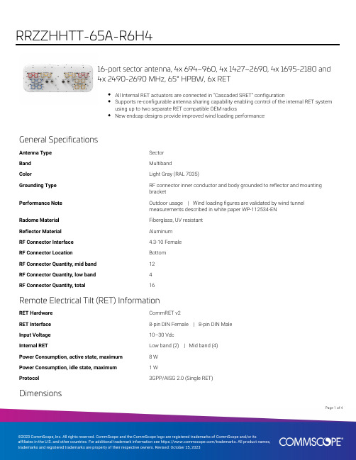
16-port sector antenna, 4x 694–960, 4x 1427–2690, 4x 1695-2180 and4x 2490-2690 MHz, 65° HPBW, 6x RETAll Internal RET actuators are connected in “Cascaded SRET” configurationSupports re-configurable antenna sharing capability enabling control of the internal RET systemusing up to two separate RET compatible OEM radiosNew endcap designs provide improved wind loading performanceGeneral SpecificationsAntenna Type SectorBand MultibandColor Light Gray (RAL 7035)Grounding Type RF connector inner conductor and body grounded to reflector and mountingbracketPerformance Note Outdoor usage | Wind loading figures are validated by wind tunnelmeasurements described in white paper WP-112534-ENRadome Material Fiberglass, UV resistantReflector Material AluminumRF Connector Interface 4.3-10 FemaleRF Connector Location BottomRF Connector Quantity, mid band12RF Connector Quantity, low band4RF Connector Quantity, total16Remote Electrical Tilt (RET) InformationRET Hardware CommRET v2RET Interface8-pin DIN Female | 8-pin DIN MaleInput Voltage10–30 VdcInternal RET Low band (2) | Mid band (4)Power Consumption, active state, maximum8 WPower Consumption, idle state, maximum 1 WProtocol3GPP/AISG 2.0 (Single RET)Dimensions498 mm | 19.606 in14Page ofPage of 24Width 498 mm | 19.606 in Depth 197 mm | 7.756 in Length1499 mm | 59.016 in Net Weight, antenna only33.9 kg | 74.737 lbArray LayoutPort ConfigurationElectrical Specifications50 ohmImpedance50 ohmOperating Frequency Band1427 – 2690 MHz | 1695 – 2180 MHz | 2490 – 2690 MHz | 694 – 960MHzPolarization±45°Total Input Power, maximum900 W @ 50 °CElectrical SpecificationsFrequency Band, MHz694–790790–890890–9601695–21802490–26901427–15181695–21802300–2690 Gain, dBi13.213.513.716.917.815.317.418.37068646856696358 Beamwidth, Horizontal,degreesBeamwidth, Vertical, degrees16.814.913.9 6.6 5.28.8 6.8 5.2Beam Tilt, degrees2–162–162–162–122–122–122–122–12USLS (First Lobe), dB1615171918171620Front-to-Back Ratio at 180°,3028283129333234dB2727272727262626Isolation, Cross Polarization,dBIsolation, Inter-band, dB2727272727272727VSWR | Return loss, dB 1.5 | 14.0 1.5 | 14.0 1.5 | 14.0 1.5 | 14.0 1.5 | 14.0 1.5 | 14.0 1.5 | 14.0 1.5 | 14.0PIM, 3rd Order, 2 x 20 W, dBc-150-150-150-150-150-150-150-150300300300250150250250200Input Power per Port at 50°C,maximum, wattsElectrical Specifications, BASTAFrequency Band, MHz694–790790–890890–9601695–21802490–26901427–15181695–21802300–269012.913.113.416.317.314.916.517.7Gain by all Beam Tilts,average, dBi±0.4±0.7±0.6±0.9±0.6±0.5±1±0.8Gain by all Beam TiltsTolerance, dBBeamwidth, Horizontal±9.1±7.5±5.1±10.8±5±8.7±7.1±8.6 Tolerance, degrees±1.1±1.5±1.3±0.7±0.2±0.6±0.8±0.4 Beamwidth, VerticalTolerance, degreesUSLS, beampeak to 20° above161214141516 beampeak, dB2122222423252527Front-to-Back Total Power at180° ± 30°, dBCPR at Boresight, dB232020192014181934Page ofCPR at Sector, dB11101274845 Mechanical SpecificationsEffective Projective Area (EPA), frontal0.47 m² | 5.059 ft²Effective Projective Area (EPA), lateral0.14 m² | 1.507 ft²Wind Loading @ Velocity, frontal503.0 N @ 150 km/h (113.1 lbf @ 150 km/h)Wind Loading @ Velocity, lateral150.0 N @ 150 km/h (33.7 lbf @ 150 km/h)Wind Loading @ Velocity, maximum604.0 N @ 150 km/h (135.8 lbf @ 150 km/h)Wind Loading @ Velocity, rear346.0 N @ 150 km/h (77.8 lbf @ 150 km/h)Wind Speed, maximum288 km/h (179 mph)Packaging and WeightsWidth, packed565 mm | 22.244 inDepth, packed309 mm | 12.165 inLength, packed1686 mm | 66.378 inWeight, gross46.8 kg | 103.176 lbRegulatory Compliance/CertificationsAgency ClassificationCHINA-ROHS Above maximum concentration valueISO 9001:2015Designed, manufactured and/or distributed under this quality management systemROHS Compliant/ExemptedUK-ROHSCompliant/ExemptedIncluded ProductsBSAMNT-3–Wide Profile Antenna Downtilt Mounting Kit for 2.4 - 4.5 in (60 - 115 mm) OD round members.Kit contains one scissor top bracket set and one bottom bracket set.* FootnotesPerformance Note Severe environmental conditions may degrade optimum performancePage of44。
泰特TB8100分析器基站 重复器产品说明书
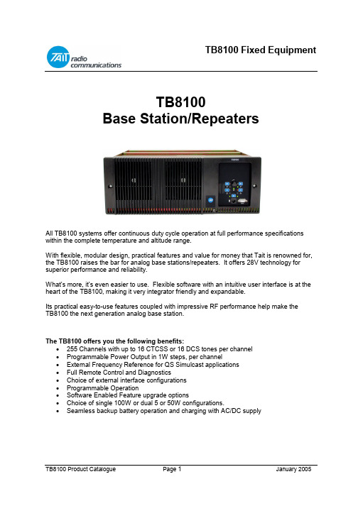
TB8100Base Station/RepeatersAll TB8100 systems offer continuous duty cycle operation at full performance specifications within the complete temperature and altitude range.With flexible, modular design, practical features and value for money that Tait is renowned for, the TB8100 raises the bar for analog base stations/repeaters. It offers 28V technology for superior performance and reliability.What’s more, it’s even easier to use. Flexible software with an intuitive user interface is at the heart of the TB8100, making it very integrator friendly and expandable.Its practical easy-to-use features coupled with impressive RF performance help make theTB8100 the next generation analog base station.The TB8100 offers you the following benefits:•255 Channels with up to 16 CTCSS or 16 DCS tones per channel•Programmable Power Output in 1W steps, per channel•External Frequency Reference for QS Simulcast applications•Full Remote Control and Diagnostics•Choice of external interface configurations• Programmable Operation•Software Enabled Feature upgrade options•Choice of single 100W or dual 5 or 50W configurations.•Seamless backup battery operation and charging with AC/DC supplyIntelligent z Flexible z High PerformanceDigital Controller DesignDesigned from the ground up, the TB8100 features a state-of-the-art RISC processor and Digital Signal Processor (DSP), providing very fast, reliable data processing through the latest in digital technology.28V TechnologyMore powerful than most base stations in its class. Tait tests the TB8100 to transmit continuously at full power with ambient air temperatures as high as 140ºF (+60ºC) at15,000 feet (4572m).Advanced Programming CapabilitiesThe TB8100’s intuitive yet comprehensive programming software with Graphical User Interface (GUI) lets you manage and program over 150 critical parameters, including all monitoring, configuration management and power management features.Convenient Modular DesignDesigned for ease of hook-up and adaptation in the field, the TB8100 is configured with front-loading modules that can be mixed and matched to meet your system needs. Whether expanding from 50 to 100 Watts, moving from single to dual channel operation, or replacing the PA or system interface board, the TB8100 gives you the flexibility to make changes in the field. A clean back-panel design hides the usual rear unit wiring clutter displaying only the connections required to link to your external radio system.User Specific ApplicationsAdditional customised programming is made easy with the TB8100 Task Manager - there's no need for intrusive hardware add-ons. TheTB8100 can readily accommodate your specific signaling, notification or alert needs. Program the unit to automatically switch to a backup base station if the self-monitor determines a problem, and choose from the wide range of alarm notification options to suit your specific solution needs. Self-Monitor CapabilityThe TB8100 manages self-monitoring parameters in its non-volatile memory, requiring no external costly monitor units, saving money, time and hassles. The advanced monitoring system will read the base status, determine the appropriate required action, and perform that action while alerting central control.Power Management SystemThe comprehensive power management system provides the ability to automatically switch between AC and DC power, to move to battery operation in the case of power failure, and to provide auxiliary battery charging and management.Complete Remote AccessibilityThe advanced intuitive interface of theTB8100 Service Kit Software makes remote management of your system simple. The self-monitoring application has dial-out capability so you are immediately notified of potential issues. Over 150 parameters on the system can be managed remotely with the TB8100 Service Kit Software.Robust SpecificationsBuilt to exceed standard specifications, the TB8100 is designed to withstand extreme temperature conditions. Engineered for maximum reliability, the TB8100 has large heat sinks, advanced cooling, and the intelligence to maintain the highest possible levels of service in adverse environments. Peak RF PerformanceWith outstanding specifications for selectivity, adjacent channel interference and fast key-up times, the TB8100 base station was designed using the best RF practices. You can depend on the RF performance of this base station even in the most extreme temperature conditions.TB8100 Base Station System PricesThe TB8100 Base Station System is shipped with the following modules included: •Subrack Front Panel with dual fans•Control Panel•Power Management Module options as selected• Power Amplifier•Reciter (Receiver/Exciter) with system interface•Service Kit (programming S/W, cable, CD)• Installation GuideSystem VHF/UHF 800MHzSingle 1-5w See price list See price listSingle 5-50w See price list See price listSingle 10-100w See price list See price listDual 1-5w See price list See price listDual 5-50w See price list See price listDual 1-5 + 5-50w See price list See price listNotes: These prices are for 12VDC systems only.For Optional Additions AddAC Power Management Unit See price listIEC Power Cord See price list12V DC, 24VDC or 48VDC Power Management Unit See price listPower Save (For Single Reciter Systems Only) See price listAlarm Reporting (Per Reciter) See price listAdvanced Profiles and Task Manager (per Reciter) See price listMicrophone See price listThese prices do not include RF equipment such as coax relays, combiners, splitters, couplers, antenna etc.For exact order details and order codes, please contact your Tait Customer Service Representative.Power Amplifiers1-5W Power AmplifierBroadband. Built-in Alarm monitoring, and diagnostics.Remotely configurable and programmable.100% duty cycle @ 60°C (140°F).2 millisecond keyup time.Programmable output power from 1 to 5W in 1W steps.Up to two 5W or 50W power amplifiers can be fitted intoa TB8100 subrack.5-50W Power AmplifierBroadband. Built-in Alarm monitoring, and diagnostics.Remotely configurable and programmable.100% duty cycle @ 60°C (140°F).2 millisecond keyup time.Programmable output power from 5 to 50W in 1W steps.Up to two 5W or 50W power amplifiers can be fitted into aTB8100 subrack.10-100W Power AmplifierBroadband. Built-in Alarm monitoring, and diagnostics.Remotely configurable and programmable.100% duty cycle @ 60°C (140°F).2 millisecond keyup time.Programmable output power from 10 to 100W in 1W steps.A limit of one 100W power amplifier can be fitted into aTB8100 subrack.Product Code Description Price TBA70B1-0000 136-174MHz, 1-5 watt PA See price list TBA70H0-0000 400-520MHz, 1-5 watt PA See price list TBA70K2-0000 760-870MHz, 1-5 watt PA See price list TBA80B1-0000 136-174MHz, 5-50 watt PA See price list TBA80H0-0000 400-520MHz, 5-50 watt PA See price list TBA80K2-0000 760-870MHz, 5-50 watt PA See price list TBA90B1-0000 136-174MHz, 10-100 watt PA See price list TBA90H0-0000 400-520MHz, 10-100 watt PA See price list TBA90K2-0000 760-870MHz, 10-100 watt PA See price listPower Management ModulesDescription: Array Single AC Power SupplyMains operated power supply. 88 to 264V input with power factorcorrection. Sufficient output power is provided to drive 1 x 100Wtransmitter or 2 x 50W transmitters. The unit has built in alarmsand diagnostics and is remotely controllable and programmable.Single DC Power SupplyA very high efficiency supply designed to run from a nominal 12, 24 or 48 VDC supply. This unit has the same output capability as the AC Power Supply. The input supply can be negatively or positively earthed. The unit has built in alarms and diagnostics and is remotely controllable and programmable.Dual (AC + DC) Power SupplyA dual power supply combining both of the above supplies. Switching from AC to DC is seamless and automatic. This option is required if the TB8100 is mains operated but is required to be powered by a backup DC supply. The DC input supply can be negatively or positively earthed. The unit has built in alarms and diagnostics and is remotely controllable and programmable.Standby Power Supply, (10W)The standby supply is highly recommended for low current consumption operation. The standby supply is used to run the Reciter alone so that the main 500 W DC supply can be switched off altogether for extended quiet periods. This unit can only be fitted to DC Supply or the Dual Supply. The low power option can only enabled for single channel operation. It is used in conjunction with the software-licensed power save feature: TBAS030.Auxiliary Power Supply / Battery Float Charger (40W output)The base station itself does not use the output of the Auxiliary Power Supply. The output is floating so it may be negatively or positively earthed.It can be configured to be on all of the time (to supply external equipment) or to be on only while mains is available (e.g. as a float charger for the battery). This module is therefore highlyrecommended for the Dual Supply and is required when the base station is to be used with TaitNetMPT1327 controllers.Single Power Supplies – see price list Product Code Input Options Output Supply OptionsAC 88-264V 10-16VDC20-33VDC40-60VDC12V Aux40W24V Aux40W48V Aux40WStandby10WTBA3001-1100 •••TBA3001-1200 •••TBA3001-1400 ••••TBA3002-2100 •••TBA3002-2200 •••TBA3002-2400 •••TBA3004-4100 •••TBA3004-4200 •••TBA3004-4400 •••TBA30A0-0100 ••TBA30A0-0200 ••TBA30A0-0400 ••Dual Power Supplies – see price listProduct Code Input Options Output Supply OptionsAC 88-264V 10-16VDC20-33VDC40-60VDC12V Aux40W24V Aux40W48V Aux40WStandby10WTBA30A1-1100 ••••TBA30A1-1200 ••••TBA30A1-1400 ••••TBA30A2-2100 ••••TBA30A2-2200 ••••TBA30A2-2400 ••••TBA30A4-4100 ••••TBA30A4-4200 ••••TBA30A4-4400 ••••Reciters (Receiver/Exciter)Reciters are available in the following bands: 136 to 156MHz, 148 to 174MHz, 174 to 193MHz,194 to 224MHz, 400 to 440MHz, 440 to 480MHz, 470 to 520MHz and 760 to 870MHz 1. Their tuning range covers a 2% subband, i.e. 10MHz at 500MHz.A Reciter includes a Receiver, Exciter, DSP, RF, and audio stages to give stable performance for the life of the product. A RISC processor controls the Task Manager, alarms system, fault monitoring, diagnostics, remote connectivity, and channel behavior.The unit has provision for an internally fitted system interface module (SIF), allowingreconfiguring of the I/O system to suit the user's requirements. There are five SIFs available.The unit is shipped with the default radio software license already installed. Other software licenses may be installed including:Alarm Reporting SoftwareAdvanced Profiles and Task Manager Software Power Saving ModesThe basic configuration includes one Reciter. An additional unit is required for any dual channel systems.Product Code Description VHF/UHF Price800MHz Price TBA40XX -YYYY Reciter with SIF included See price list See price listWhere XX is:B1=136-156MHz B2=148-174MHz B3=174-225MHz H1=400-440MHz H2=440-480MHz H3=480-520MHz K4=760-870MHzWhere YYYY is the Reciter with the following SIF:0A00 = Non-isolated 0B00 = Isolated Audio0C00 = Isolated Audio E/M 0T10 = TaitNet, MPT Trunked 0L00 = TaitNet, MPT + RS2321Note 800 MHz band covers 754-776 & 850-870 TX, 794-829 RX.System Interface CardsThe Reciters have a position inside for a System Interface (SIF) card. The SIF is responsible for all the non-RF inputs and outputs for the reciter. The SIF is interchangeable depending on the application requirements.One of the following SIFs may be selected per reciter.Non Isolated Audio D25 Connector with:Æ Balanced and unbalanced input and output audio lines, Æ 6 digital inputs, Æ 2 digital outputs, Æ 4 digital input/outputs Æ 1 coax relay drive output, Æ Tx Key & Rx Gate.Isolated Audio D25 connector with:Æ Transformer isolated balanced input and output audio lines, Æ Non isolated unbalanced input and output audio lines, Æ 6 digital inputs, Æ 2 digital outputs, Æ 4 digital input/outputs Æ 1 coax relay drive output, Æ Tx Key & Rx Gate.Isolated Audio E&M D25 connector with:Æ Transformer isolated balanced input and output audio lines, Æ Non isolated unbalanced input and output audio lines, Æ 2 digital inputs, Æ 2 digital outputs, Æ 4 digital input/outputs Æ 1 coax relay drive output, Æ Tx Key & Rx Gate, Æ Optically isolated E & M (Tx Key and Rx Gate).TaitNet, RS232D15 connector to interface directly with TaitNet system, with:Æ Balanced and unbalanced input and output audio lines, Æ 1 digital input, Æ 3 digital outputs, Æ Tx Key & Rx Gate Æ D9 RS232 connector.TaitNet, MPT TrunkedD15 connector to interface directly with TaitNet system, with:Æ Balanced and unbalanced input and output audio lines, Æ 1 digital input, Æ 3 digital outputs, Æ Tx Key & Rx Gate.SubracksIn order to house the modules, you need to select one of the following subracks:Description 5/50W 100W Single Reciter Systems See price list See price list Dual Reciter Systems See price list Not Available Power Save Systems See price list See price listNOTE:PowerSave is only available in Single Reciter Systems.Software Enabled FeaturesThe TB8100 Software feature enabler is a software licensing system that is used to enable advanced features of the base station.Licenses are applied on a per-feature and per-reciter basis. Alarm Reporting SoftwareThe TB8100 Base Station supports some key alarm systems that will form the backbone of any well-configured radio system. The key features are:• Task Manager initiation of Status and Alarm calls • Alarm Centre package (standalone PC application)Æ Alarm collection Æ Email forwarding• External alarm inputs to base stationThis license must be purchased on a per reciter basisAdvanced Profiles and Task Manager SoftwareSignalling :Up to 16 sub-audible receive tones (CTCSS or DCS). No limits to the combinations for CTCSS and DCS.Tx tone selectable per input tone for repeater operation. Tx tone selectable for Line Controlled base operationSignal Path:Dual audio paths on both transmit and receive.Audio filtering characteristic independently selectable for both receive paths and both transmit paths.Tx Power:Power adjustable independently for mains and battery operationChannel Spacing:Cross-system repeating possible with independently selectable receiver and transmitter bandwidth (25kHz, 20kHz or 12.5kHz)Task ManagerUp to 200 enabled tasks.Far greater scope for better system control andfault & alarm management.Advanced ProfilesUp to 16 customised channel profiles and signallingprofiles are available.Base station behaviour changes on a per-profile basis.Power Saving ModesIn power saving mode the receiver cycling time can beas slow as one second. If the PMU has a standby supplyfitted, the reciter will also switch off the main circuitryof the PMU when not needed. Power savings aretherefore dramatic. If there is line or signal activity,the power supply is completely re-booted to wake thesystem. The standby supply has been carefully optimisedto power just a single reciter, and is not suitable if thesubrack has more than one reciter.This license must be purchased on a per reciter basis.Product Code Description PriceTBAS010 Alarm Reporting Remote Control & DiagnosticsDial-up reporting and e-mailSee price listTBAS020Advanced Profiles and Task ManagerDefault profiles, 16 CTCSS or DCS tones, Dual audiopaths Full task manager (200 tasks)See price listTBAS030Power Saving ModeProgrammable low current drain features. RequiresDC Power Management Unit and standby supply.See price listStandard AccessoriesTMAA02-01 MicrophoneRequired for test transmissions. Plugs into the UserInterface. The microphone can be configured totransmit over the air or as line audio.See price listPower CordsetsProduct Code Description PriceTBA0001-AU IEC Cordset (Aust/NZ/China)TBA0001-US IEC Cordset (USA/Canada/Middle East)See price list T952-320 IEC Cordset (Singapore/UK/Hong Kong)T952-330 IEC Cordset (Mainland Europe)Service AccessoriesTBA0ST1 Calibration Test UnitThe TB8100 Calibration Test Unit is required whenusing the Service Kit to access the reciter when it isnot in the subrack.It is required for system re-tuning and extremely usefulfor system test and run-up, especially whencommissioning new configurations, and running radio diagnostics.See price listTBA0ST2 Tool KitComprising of:Control Panel Board RemoverTorx-Driver T8Torx-Driver T10Torx-Driver T20Screwdriver PZD-2Screwdriver Medium Flat BladeTuning Tool Cer 2.2mmTuning Tool 5CCESocket Head M3 nutsTool bagSee price list。
PmodGYRO2 高性能单轴陀螺仪说明书
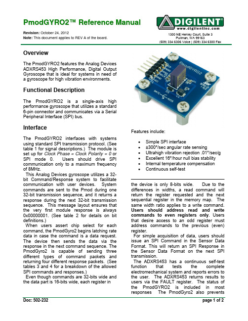
P m o d G Y R O 2™ R e f e r e n c e M a n u a lRevision: October 24, 2012Note: This document applies to REV A of the board.1300 NE Henley Court, Suite 3Pullman, WA 99163(509) 334 6306 Voice | (509) 334 6300 FaxDoc: 502-232page 1 of 2OverviewThe PmodGYRO2 features the Analog Devices ADXRS453 High Performance, Digital Output Gyroscope that is ideal for systems in need of a gyroscope for high vibration environments.Functional DescriptionThe PmodGYRO2 is a single-axis high performance gyroscope that utilizes a standard 6-pin connector and communicates via a Serial Peripheral Interface (SPI) bus.InterfaceThe PmodGYRO2 interfaces with systems using standard SPI transmission protocol. (See table 1 for signal descriptions.) The module is set up for Clock Phase = Clock Polarity = 0 or SPI mode 0. Users should drive SPI communication only to a maximum frequency of 8MHz.This Analog Devices gyroscope utilizes a 32-bit Command/Response system to facilitate communication with user devices. System commands are sent to the Pmod during one 32-bit transmission sequence, and it returns a response during the next 32-bit transmission sequence. This message layout ensures that the very first module response is always 0x00000001. (See table 2 for details on bit definitions.)When users assert chip select for each command, the PmodGyro2 begins latching rate data in case the command is a data request. The device then sends the data via the response in the next command sequence. The PmodGyro2 is capable of sending three different types of command packets and returning four different response packets. (Seetables 3 and 4 for a breakdown of the allowed SPI commands and responses.)Even though commands are 32-bits wide and the data part is 16-bits wide, each register inFeatures include:∙ Simple SPI interface∙ ±300°/sec angular rate sensing∙ Ultrahigh vibration rejection .01°/sec/g ∙ Excellent 16°/hour null bias stability ∙ Internal temperature compensation ∙ Continuous self-testthe device is only 8-bits wide. Due to the differences in widths, a read command will return the register requested and the next sequential register in the memory map. The same width ratio applies to a write command. Users should address read and write commands to even registers only . Users that desire access to an odd register must address commands to the previous (even) register.For simple acquisition of data, users should issue an SPI Command in the Sensor Data Format. This will return an SPI Response in the Sensor Data Format on the next SPI transmission.The ADXRS453 has a continuous self-test function that tests the complete electromechanical system and reports errors to the user. The ADXRS453 returns results to users via the FAULT register. The status of the PmodGYRO2 is included in most responses The PmodGyro2 also preventsPmodGYRO2 Reference Manual page 2 of 2Copyright Digilent, Inc. All rights reserved. Other product and company names mentioned may be trademarks of their respective owners.temporary spikes in data from causing a failing status response by filtering raw data from the self-test before sending a pass/fail status. The module stores both the raw data and the filtered data in the HICSTx and LOCSTx registers. Users may access this data should they be concerned about these energy spikes. The temperature sensor data is useful for temperature compensation of the rate data and is also directly available to the user. To get the temperature sensor data users must simply execute a read command of the TEMx registers from the device.Table 1: Interface Connector SignalDescriptionNote: For more information on the GYRO2 module interface, see the ADXRS453 datasheet available online from Analog Devices at .Table 2: SPI Bit DefinitionsTable 3: SPI CommandsTable 4: SPI Responses。
GYRO RGB LASER 152.761UK用户手册说明书

Caution: At the last fixture, the DMX-cable has to end with a terminator. Solder a 120 Ohm resistor between PIN 2 (-) and PIN 3 (+) into a 3-pin XLR-plug and plug it in the DMX-output of the last fixture. When in DMX mode there are two channels with the following function:
TECHNICAL SPECIFICATION
Voltage : 230Vac, 50/60Hz Fuse : 2A Slow blow
Laser Class : 3B Red Laser: 100mW 638nm Green Power : 50mW 532nm
Blue : 30imensions : 190 x 190 x 110mm
AUt SOU rgb P00-P19 001-512
Function
Auto running random effects cycle Sound activated random effects cycle Colour select mode Gobo Select DMX address
• This product must not be used for any form of audience scanning application and is for professional use only.
152.761UK User Manual
152.761UK User Manual
USB-Adapter2000快速指南说明书
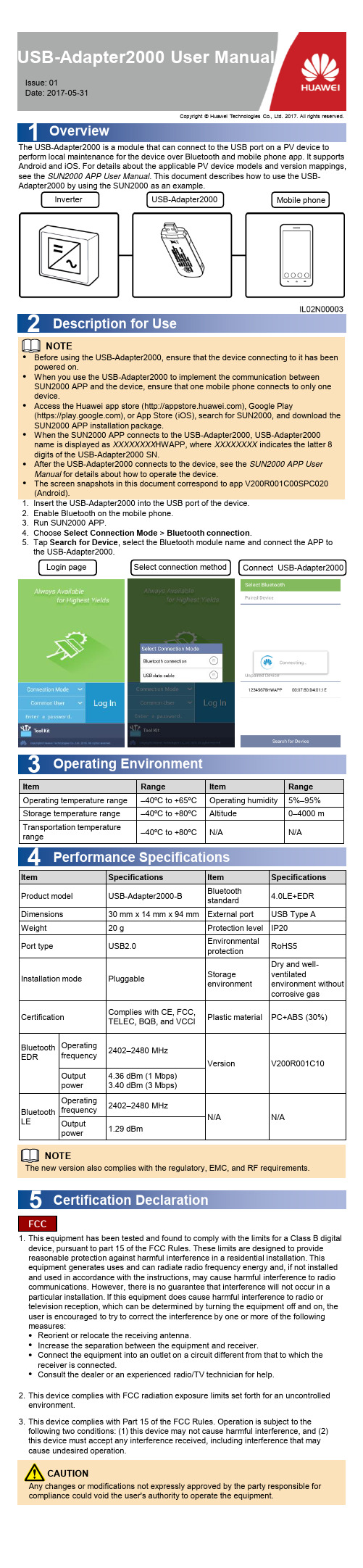
USB-Adapter2000 Quick Guide USB-Adapter2000 User Manual Issue: 01Date: 2017-05-311OverviewThe USB-Adapter2000 is a module that can connect to the USB port on a PV device to perform local maintenance for the device over Bluetooth and mobile phone app. It supports Android and iOS. For details about the applicable PV device models and version mappings, see the SUN2000 APP User Manual . This document describes how to use the USB-Adapter2000 by using the SUN2000 as an example.●Before using the USB-Adapter2000, ensure that the device connecting to it has been powered on.●When you use the USB-Adapter2000 to implement the communication between SUN2000 APP and the device, ensure that one mobile phone connects to only one device.●Access the Huawei app store (), Google Play(https://), or App Store (iOS), search for SUN2000, and download the SUN2000 APP installation package.●When the SUN2000 APP connects to the USB-Adapter2000, USB-Adapter2000 name is displayed as XXXXXXXX HWAPP, where XXXXXXXX indicates the latter 8 digits of the USB-Adapter2000 SN.●After the USB-Adapter2000 connects to the device, see the SUN2000 APP User Manual for details about how to operate the device.●The screen snapshots in this document correspond to app V200R001C00SPC020 (Android).1.Insert the USB-Adapter2000 into the USB port of the device.2.Enable Bluetooth on the mobile phone.3.Run SUN2000 APP.4.Choose Select Connection Mode > Bluetooth connection .5.Tap Search for Device , select the Bluetooth module name and connect the APP to the USB-Adapter2000.NOTE3Operating EnvironmentItemRange ItemRange Operating temperature range –40ºC to +65ºC Operating humidity 5%–95%Storage temperature range –40ºC to +80ºC Altitude 0–4000 m Transportation temperaturerange–40ºC to +80ºCN/AN/A4Performance SpecificationsItem Specifications Item Specifications Product model USB-Adapter2000-B Bluetooth standard 4.0LE+EDR Dimensions30 mm x 14 mm x 94 mm External port USB Type A Weight20 g Protection level IP20Port typeUSB2.0Environmental protection RoHS5Installation mode PluggableStorage environmentDry and well-ventilatedenvironment without corrosive gas CertificationComplies with CE, FCC, TELEC, BQB, and VCCI Plastic materialPC+ABS (30%)Bluetooth EDROperatingfrequency 2402–2480 MHzVersionV200R001C10Output power4.36 dBm (1 Mbps)3.40 dBm (3 Mbps)Bluetooth LE Operatingfrequency 2402–2480 MHzN/AN/AOutputpower1.29 dBmCertification Declaration51.This equipment has been tested and found to comply with the limits for a Class B digital device, pursuant to part 15 of the FCC Rules. These limits are designed to provide reasonable protection against harmful interference in a residential installation. This equipment generates uses and can radiate radio frequency energy and, if not installed and used in accordance with the instructions, may cause harmful interference to radio communications. However, there is no guarantee that interference will not occur in a particular installation. If this equipment does cause harmful interference to radio or television reception, which can be determined by turning the equipment off and on, the user is encouraged to try to correct the interference by one or more of the following measures:●Reorient or relocate the receiving antenna.●Increase the separation between the equipment and receiver.●Connect the equipment into an outlet on a circuit different from that to which the receiver is connected.●Consult the dealer or an experienced radio/TV technician for help.2.This device complies with FCC radiation exposure limits set forth for an uncontrolled environment. 3.This device complies with Part 15 of the FCC Rules. Operation is subject to thefollowing two conditions: (1) this device may not cause harmful interference, and (2) this device must accept any interference received, including interference that may cause undesired operation.Any changes or modifications not expressly approved by the party responsible for compliance could void the user's authority to operate the equipment.FCCCAUTIONLogin pageSelect connection methodConnect USB-Adapter20002Description for UseInverterUSB-Adapter2000Mobile phoneCopyright © Huawei Technologies Co., Ltd. 2017. All rights reserved.NOTEThe new version also complies with the regulatory, EMC, and RF requirements.。
ADRV9026四通道宽带RF接收器平台商品介绍说明书

VISIT ADRV9026Quad-Channel, Wideband RF Transceiver Platform200 MHz Bandwidth Integrated Radio Transceiver SolutionApplications►Macro base stations ►Massive MIMO►Small cell designs1See page 3 for future enhancements in the ADRV902x family roadmapSmallest Size, Lowest Power Transceiver Solution for Base Transceiver Stations (BTS )►Smallest size reduces footprint and enhances form factor flexibility►50% power consumption reduction over previous generation ADRV9009 for increased radio density►Enables ORAN small cell designs with lowest system power and costHighly Integrated, High Performance Software-Defined Radio►2× integration over ADRV9009►Supports up to 200 MHz bandwidth and covers all bands from 650 MHz to 6 GHz 1Common Platform Design for 3G/4G/5G Reduces Complexity, Development Costs, and Time to Market►Single-chip FDD/TDD solution simplifies hardware and software development ►Common API across multiple applications►Reduces product development cycles for band and power variants►Enables modular architecture for scalable radio solutionsADRV9026 Quad-Channel, Wideband RF Transceiver Platform RF SynthRF Synth ORX1/ORX2TX 1TX 2RX10°90°RX2RX3+RX3–RX4+RX4–RX1+RX1–RX2+RX2–TX3+TX3–TX4+TX4–TX1+TX1–TX2+TX2–ORX3+ORX3–ORX4+ORX4–ORX2+ORX2–ORX1+RF SynthLO 1LO 2GPIO AuxADC AuxDACGPINT1JESD204B/C Serial InterfaceClock GenerationandSynchronizationDEVCLK±SYSREF±LO 2LO 1LO 2LO 1RX3, RX4, TX3, TX4, ORX 3/ORX4RX1, RX2, TX1, TX2, ORX 1/ORX2pFIR,LO Leakage,QEC, Tuning,InterpolationGPIO_ANA_n AUXADC_nSPI_CLKSPI_EN SPI_DO SPI_DIORXn_EN TXn_EN ORXn_EN VDDA_1P8VDDA_1P3VDDA_1P0VDIG_1P0EXT_LO1±EXT_LO2±PWR MGMTGPINT2RESET TESTSERDOUTA±SYNCIN1±SYNCIN2±SYNCIN3±SERDINA±SERDINB±SERDINC±SERDIND±LO 3LO 3SYNCOUT1±SYNCOUT2±8419VIF444SERDOUTB±SERDOUTC±SERDOUTD±MicroprocessorADCADCDACDACADCADCDecimation,pFIR,DC Offset,QEC,Tuning,OverloadDecimation,pFIR, AGC,DC Offset,QECTuning RSSI,OverloadControl InterfaceSPI Port0°90°0°90°2ADRV9026 Quad-Channel, Wideband RF Transceiver Platform3Visit ADRV9026 Overview►Four differential transmitters ►Four differential receivers►Two observation receivers with two inputs each ►Center frequency: 650 MHz to 6000 MHz ►Maximum receiver bandwidth: 200 MHz ►Maximum transmitter bandwidth: 200 MHz►Maximum transmitter synthesis bandwidth: 450 MHz►Maximum observation receiver bandwidth: 450 MHz►Fully integrated independent fractional-N radio frequency synthesizers ►Fully integrated clock synthesizer►Multichip phase synchronization for all local oscillators and baseband clocks ►Support of TDD/FDD 3G/4G/5G applications►16 Gbps JESD204B/C digital interfaceSee roadmap below for future enhancementsADRV9026 Family RoadmapEnhanced features and functions will be added to the ADRV9026 over time, including:►25 Gbps SERDES support►Extending LO frequency range down to 75 MHz►Support for an external LO►Filter Wizard to generate custom profilesAn enhanced version from the ADRV902x family will be released in 2020 with integrated DPD and CFR, reducing FPGA requirements, as well as lowering total system power and cost.RadioVerse Ecosystem and PartnershipsRadioVerse ® is a design and technology ecosystem for advanced radio design and development. We offer market-leading integrated transceiver technology, software tools, evaluation and prototyping platforms, a range of reference designs, and radio solutions. RadioVerse is building up a global partnership network to provide customers all levels of design support. ADRV9026’s partner network and reference design ecosystem will be launched on /radioverse in 2020.Evaluation SystemThe evaluation system comprises an FPGA carrier board ADS9-V2EBZ and a radio daughtercard, coming with two frequency bands of matching: –HB for 2.8 GHz to 6 GHz and –MB for 650 MHz to 2.8 GHz. Compatible evaluation software is provided for download, including API library, Windows GUI, and a binary image for FPGA configuration.Radio CardsCarrier BoardsSoftware and DriverE v a l u a t i o n S y s t e m►ADRV902X-HB/PCBZ (for 2.8 GHz to 6 GHz )►ADRV902X-MB/PCBZ (for 650 MHz to 2.8 GHz )►ADS9-V2EBZ(FPGA motherboard with Xilinx ® UltraScale+™)►Operating system-agnostic API source in ANSI C►Windows GUI for transceiver configuration and data capture►Binary image for FPGA configurationFor regional headquarters, sales, and distributors orto contact customer service and technical support, visit /contact.Ask our ADI technology experts tough questions, browse FAQs, or join a conversation at the EngineerZone Online Support Community. Visit .©2019 Analog Devices, Inc. All rights reserved. Trademarks and registered trademarks are the property of their respective owners.PH21775-11/19(A)VISIT 。
艾顿 DC 切换器 PV-DIS 2 螺纹线路产品说明说明书

xEffect - Industrial Switchgear RangeDC Switch-Disconnector PV-DIS 2-polesCatalog1.1Photovoltaic - DC-DisconnectionDC Switch-Disconnector PV-DIS 2-poles• P hotovoltaic - Switch-disconnectors • A cc .to EN 60947-3 DC-PV1 or DC-PV2 resp.• V ery compact• I mproved reliability due to independent manual operation• S table performance at any load current • P olarity independent• O nly one path per pole => lower power lossDescriptionsg096151.2Photovoltaic - DC-DisconnectionDC Switch-Disconnector PV-DIS 2-polesRated operating current I e Type Article No.Units per(A)Designationpackagesg0961516PV-DIS-06-16/2-ROT179259132PV-DIS-06-32/2-ROT179260163PV-DIS-06-63/2-ROT1792611100PV-DIS-06-100/2-ROT1855031125PV-DIS-06-125/2-ROT17926212-poles with rotary handle, 600 V16PV-DIS-08-16/2-ROT179263132PV-DIS-08-32/2-ROT179264163PV-DIS-08-63/2-ROT1792651100PV-DIS-08-100/2-ROT1855041125PV-DIS-08-125/2-ROT17926612-poles with rotary handle, 800 V16PV-DIS-10-16/2-ROT179267132PV-DIS-10-32/2-ROT179268163PV-DIS-10-63/2-ROT1792691100PV-DIS-10-100/2-ROT1855051125PV-DIS-10-125/2-ROT17927012-poles with rotary handle, 1000 V16PV-DIS-06-16/2179255132PV-DIS-06-32/2179256163PV-DIS-06-63/21792571100PV-DIS-06-100/21855021125PV-DIS-06-125/217925812-poles without rotary handle, 600 V1.3Photovoltaic - DC-DisconnectionDC Switch-Disconnector PV-DIS 2-poles - Technical DataTechnical DataPV-DIS-06…PV-DIS-08…PV-DIS-10…Rated operating voltage600 V 800 V 1000 V Rated impulse withstand voltage4 kV 6 kV6 kVPV-DIS-…/2PV-DIS-…/2-ROT Rated insulation voltage630 V1000 VUtilization category (acc. to EN 60947-3)Rated operating current I e 16-100 A DC-PV2Rated operating current I e 125 A DC-PV1Mechanical operations acc. to IEC 60947-3 Category of utilization DC-PV2 or DC-PV1Electrical operationsacc. to IEC 60947-3 Category of utilization DC-PV2 or DC-PV1Rated frequency / Operating frequency DC only ApprobationÖVE, VDE Resistance to climatic conditions according to IEC 60947-2Shock resistance, Vibration resistance acc. to IEC 60947-2Dimensionsaccording to drawing Dimensions of terminals 2.5-50 mm 2Cable materialCu Degree of protectionIP20Degree of protection, built-in IP40Mounting positionDIN-Rail, Rotation +90°, -90°, 180°Ambient temperature range 40 to +85 °C Storage Temperature 40 to +85 °C Max. DC contact rating 100 %Safe electrical isolation yesSupply side interchangeable PolarityinterchangeableWiring Examples--+--+---1.4Photovoltaic - DC-DisconnectionDC Switch-Disconnector PV-DIS 2-poles - T echnical DataDimensions (mm)2-poles with rotary handle2-poles without rotary handle1.5Photovoltaic - DC-DisconnectionDC Switch-Disconnector PV-DIS 2-poles - Technical DataDC-PV1: Switching of single PV string(s) without reverse and overcurrents DC-PV2: Switching of several PV strings with reverse and overcurrentsRated operating current at different voltages2-poles with rotary handle, 600V1.6Photovoltaic - DC-DisconnectionDC Switch-Disconnector PV-DIS 2-poles - T echnical DataDC-PV1: Switching of single PV string(s) without reverse and overcurrents DC-PV2: Switching of several PV strings with reverse and overcurrentsRated operating current at different voltages2-poles with rotary handle, 1000 V9010238151925EatonEMEA Headquarters Route de la Longeraie 71110 Morges, Switzerland © 2021 EatonAll Rights Reserved Printed in AustriaPublication No. CA003023EN Article number 302013-MK April 2021Eaton Industries (Austria) GmbH Scheydgasse 421210 Vienna AustriaFollow us on social media to get the latest product and support information.Eaton is a registered trademark.All other trademarks are property To contact us please visit https:///us/en-us/support/international-support-contacts.htmlFor technical questions please contact your local Eaton team.Changes to the products, to the information contained in thisdocument, and to prices are reserved; as are errors and omissions.Only order confirmations and technical documentation by Eaton is binding. Photos and pictures also do not warrant a specific layout or functionality. Their use in whatever form is subject to prior approval by Eaton. The same applies to trademarks (especially Eaton, Moeller,and Cutler-Hammer). The Terms and Conditions of Eaton apply, as referenced on Eaton Internet pages and Eaton order confirmations.Eaton’s electrical business is a global leader with deep regionalapplication expertise in power distribution and circuit protection; power quality, backup power and energy storage; control and automation; life safety and security; structural solutions; and harsh and hazardous environment solutions. Through end-to-end services, channel and an integrated digital platform & insights Eaton is powering what matters across industries and around the world, helping customers solve their most critical electrical power management challenges.For more information, visit .。
泽尔特光电产品说明书

Prism TM seriesdiffuse refl ective sensors, OEM versionModels covered in this manual:8-Inch diffuse reflective modelsDC power with Cable DC power with connectorViewing style:Light operate Dark operate Light operate Dark operateNPN output Forward13156ALN1713156ADN1713156ALN0713156ADN07 Right angle13156RLN1713156RDN1713156RLN0713156RDN07PNP output Forward13156ALP1713156ADP1713156ALP0713156ADP07 Right angle13156RLP1713156RDP1713156RLP0713156RDP07NPN/PNP output Forward13156AL1713156AD1713156AL0713156AD07 Right angle13156RL1713156RD1713156RL0713156RD07 24-Inch diffuse reflective modelsDC power with cable DC power with connectorViewing style:Light operate Dark operate Light operate Dark operateNPN output Forward13157ALN1713157ADN1713157ALN0713157ADN07 Right angle13157RLN1713157RDN1713157RLN0713157RDN07PNP output Forward13157ALP1713157ADP1713157ALP0713157ADP07 Right angle13157RLP1713157RDP1713157RLP0713157RDP07NPN/PNP output Forward13157AL1713157AD1713157AL0713157AD07 Right angle13157RL1713157RD1713157RL0713157RD07a Contact factory for availability on these models.aa a a aa a a aa a a aa a a aa a a aa a aCAUTIONTHESE PRODUCTS ARE NOT DESIGNED, TESTED,OR RECOMMENDED FOR USE IN HUMAN SAFETY APPLICATIONS.MAXIMUM INPUT VOLTAGE FOR DC OPERATION IS30 VDC. APPLYING VOLTAGE ABOVE THIS LIMIT WILL RESULT IN DAMAGE TO THE SENSOR.USE #4 MOUNTING HARDWARE ONLY! LARGER HARDWARE WILL DAMAGE THE SENSOR AND MAY CREATE AN ELECTRICAL SHOCK HAZARD. TIGHTEN THE HARDWARE JUST TO THE SENSOR BODY SO THAT NO DEFLECTION OF THE BODY OCCURS.DO NOT USE TOOLS TO APPLY TORQUE DIRECTLY TO SENSOR BODY. ALIGN SENSOR BY HAND BEFORE TIGHTENING MOUNTING HARDWARE.THE GAIN POT IS A 3/4 TURN POT. ANY RESISTANCE ENCOUNTERED WHILE ADJUSTING THIS POT INDICATES YOU HAVE REACHED THE ADJUSTMENT LIMIT STOP. TURNING PAST THIS STOP WILL DAMAGE THE SENSOR.SHORT CIRCUIT PROTECTION WILL AUTOMATICALLY RESET ONCE SHORT IS REMOVED.IntroductionA diffuse reflective sensor operates by shininga beam of light out through the lens. When an object comes within the sensor’s view, it reflects part of this beam of light back to the sensor causing the sensor to detect the object. The maximum range at which a given object can be detected depends on how well its surface reflects light—the less light it reflects back, the shorter the range. The ability of a surface to reflect light depends primarily upon its material of construc-tion, color, and texture.This manual covers both forward viewing and right angle viewing models. Although the units differ in the location of the lenses, the basic fundamentals of installation, set-up, and operation are nearlyidentical.ForwardviewingMountingMounting location and set-upThe Prism sensor features a threaded housing and includes jam nuts and washers. This allows mounting into any 0.75 inch hole, or optional bracket. Use caution to avoid cross-threading the jam nuts on the sensor body. Tighten nuts to less than 4 N•m (36 in.-lbs. or 3 ft.-lbs.) torque to avoid stripping threads.A second mounting method is to use #4 hardware in the 0.125 inch diameter mounting holes in the flat sides of the sensor. This is ideal for mounting the Prism against a wall, piece of equipment, rail, mounting bracket, etc.Select a mounting location with a clear view of the object to be detected. Avoid direct reflection from a highly reflective background (or darken the background). Mount the sensor so that it points at the most suitable part of the target object.Be sure your power supply is off, then connect the sensor to thecontrol circuit and power lines. Turn the power supply on and place a sample object in the beam. Slowly turn the gain adjustment clockwise (see Warning above concerning pot adjustment) until the LED lights (for light-operate model). Note the position and remove the sample object. Now continue turning the gain setting clockwise to find the position where the LED lights from the background reflec-tion. Reset the gain midway between the two positions. Tighten all mounting screws.ote: N If background reflections are low, it will be possible to achieve a maximum gain setting without the LED lighting; in that case, set the gainmidway between the first setting and maximum (this will prevent a hysteresislatch-up after sensing an object).2Installation Instructions 110210-305Effective January 2017EATON Prism TM seriesdiffuse refl ective sensors, OEM versionetected.SpecificationsDC modelsInput voltage 10 to 30 V DC, reverse polarity protected Power dissipation 1 W maximumOutput type NPN only, PNP only, or NPN and PNP by modelOutput operationDark operate models: ON when beam is blocked; OFF when beam is not blocked Light operate models: ON when beam is not blocked; OFF when beam is blocked Current switching capacity 100 mA maximum Off-state leakage 10 mA maximumOn-state voltage dropNPN: 2.0 V at 100 mA; PNP: 2.5 V at 100 mA Short circuit protection Protected against dead shorts only.Operation: Output is continuously retried at 3 mS intervals and will automatically reset when short is removed (no visual indication of a short circuit condition).CAUTION: will not protect against overloads between 100 mA and 1 A.Response time 1.2 mSLight/dark operation Specified by model numberTemperature range Operating: -25° to 55° C (-13° to 131° F), Storage: -25° to 70° C (-13° to 158° F)Sunlight immunity 1,000 foot-candlesMaterial of construction Lens: Polycarbonate; Cable jacket: PVC; Body: Structural polyurethane foam (do not expose to concentrated acids, alcohols, or ketones)Cable models 6-foot long; 3-wire NPN or PNP models; 4-wire NPN/PNP models Connector models Micro Connector, 4-pin maleVibration and shock Vibration: 30g over 10 Hz to 2 kHz; Shock: 50 g for 10 mS 1/2 sinewave pulse Indicator led Lights steady when output is ON; OFF when output is OFF;OFF when output is in short circuit modeAlarm indicator led ON in condition of low gain or noise interferance; OFF in normal condition Enclosure ratings NEMA 1, 2, 3, 4, 4X, 6, 12, and 13 (See note below)ApprovalsContact factory for latest list of agency approvalsote: N Our products conform to NEMA tests as indicated, however, some severe washdown applications can exceed these NEMA test specifications. If you have questions about a specific application, contact our Applications Department.3Installation Instructions 110210-305Effective January 2017EATON Prism TM series diffuse refl ective sensors, OEM version Wiring diagramsNPN modelsPNP modelsNPN/PNP modelsOptical performanceOptical performance(Shown in inches except where noted)All optical specifications are guaranteed to be the minimum perfor-mance under clean conditions of any product delivered from stock.Typical performance may be higher.Dirt in the environment will affect optical performance by reducingthe amount of light the control receives. For best results, sensorsshould be used at distances where excess gain is higher than 1.5(1.5 times the amount of sensing power required to detect an objectunder ideal conditions). Higher excess gain will allow the sensor toovercome higher levels of contamination on the lens. All ranges andexcess gain graphs are based on a 90% reflectance white card.1315613157Source Infrared, 880 nm Infrared, 880 nmMaximum range8 inches (203 mm)24 inches(609mm)Optimum range0.1-5 inches(3-127 mm)0.1-15 inches(3-381mm)Field of view2 inch (51 mm) diameterat 5 inches (127 mm)6 inches (152 mm) at15 inches (381 mm)Eaton1000 Eaton BoulevardCleveland, OH 44122United States© 1999 EatonAll Rights ReservedEaton is a registered trademark.All other trademarks are propertyof their respective owners. Installation Instructions 110210-305Effective January 2017Prism TM seriesdiffuse refl ective sensors, OEM version。
振动陀螺

5
2.1 音叉陀螺: 结构
原理:
振动的端部质量和基座的转动耦合产生的苛氏效应
结构:
U 型的弹性臂. 受到激励后,两臂做对称振动,导致 两个端部质量做对称的线振动
几百或几千 Hz, 幅值相同(几百 mm) 相位相反 音叉底部与基座挠性连接
音叉 挠性轴 基座
阻尼器
Lecture 15 -- Vibratory Gyro
假设,绕 着中心轴
角位移 --------------θ 转动惯量 ----------- J 阻尼比 -------------- c 扭转刚-- ------------ k
T
ac
x Fc
v
v
Fc
ac
s0
s0
则绕中心轴转动的动态方程可以写成:
J c k Tm cosnt
振动陀螺:
原理 ---- 利用振动的质量随着基座旋转 时产生的苛氏加速度
特点 --- 简单, 轻小, 可靠, 便宜
Lecture 15 -- Vibratory Gyro
3
1.1 振动陀螺: 发展历程
Development:
1940s-50s --- 美国研制音叉陀螺 1960s --- 通用汽车研制压电陀螺. 1970s后期 --- Delco 公司研制半球谐振陀螺 1980s早期 --- Draper 和 Sperry 研制 MEMS 陀螺 精度: 音叉, 压电, MEMS:
ac
x Fc
v
v
Fc
ac
s0
s0
苛氏惯性力
Fc
mபைடு நூலகம்2
ac
mxmn
VIAVI 4100-Series DWDM OTDR 模块(用于 T-BERD MTS-2000、
VIAVI Solutions Data SheetVIAVIDWDM OTDR Module (4100-Series)For T-BERD®/MTS-2000, -4000 V2, -5800, CellAdvisor 5Gand OneAdvisor-800 PlatformsAs xWDM technology adoption continues to grow in access networks for broadbandservices, technicians require comprehensive and lightweight xWDM test tools.Consisting of a single module, the VIAVI C-band DWDM OTDR solution enables cable,wireless, and telco operators to perform complete end-to-end link characterizationand troubleshooting of DWDM and hybrid CWDM/DWDM networks.Key Benefitsy Characterize fiber links with exactDWDM wavelengthsy Troubleshoot live networks with in-servicetesting capabilityy Verify end-to-end continuity through MUX/DEMUX and ROADMs using the continuouswave source functiony Automatically identify and test DWDM portchannel/link with patented Wavescany Avoid accidental transceiver damagewith SFP ProtectKey Featuresy C-Band (1528nm to 1568nm) tunableDWDM OTDR module at ITU-T G.694.1wavelengths (CH12 to CH62)y Integrated CW light source withmodulation capabilityy Instantaneous traffic detectiony Automatically identify Mux and Demuxcomponents with SmartLink MapperApplicationsy Metro & access rings, business to business,advanced C-RAN fronthauls & next genFTTH networksy Qualification of fronthaul access networksy Testing new DWDM wavelengthroutes without disrupting traffic onactive channelsy Pinpointing faults and their exactlocations while in serviceThe DWDM OTDR module’s optical performance, combinedwith the complete suite of T-BERD/MTS, CellAdvisor 5G andOneAdvisor-800 platform testing features, ensures thatcomprehensive testing is done right the first time.Standard testing features include:y Auto-setting of the acquisition parametersy Summary results table with pass/fail analysis per theinternational standardsy Comprehensive event diagnosisy FastReport onboard report generationT-BERD/MTS-2000One-slot handheldmodular platform forfiber network testingHandheld testinstrument for 10 GEthernet and fibernetworks testingTwo-slot handheldmodular platformfor fiber/copper andmultiple services testingT-BERD/MTS-4000 V2T-BERD/MTS-5800CellAdvisor 5GCell site test solutionOneAdvisor-800All-in-One Cell-siteInstallation andMaintenanceT est Solution2020 Broadband Technology Review ‒4.5 Diamond Award Winner2 VIAVI T-BERD/MTS 4100 Series DWDM OTDR ModuleSpecifications (typical at 25°C)2. The one-way difference between the extrapolated backscattering level at the start of the fiber and the RMS noise level, after 3 minutes averaging and using the largest pulsewidth.3. Measured at ±1.5 dB down from the peak of an unsaturated reflective event using the shortest pulsewidth.4. Measured at ±0.5 dB from the linear regression using a FC/PC reflectance and using the shortest pulsewidth.5. Subtract 3 dB when used in modulation mode (270/330/1/2 kHz).For more information on the VIAVI T-BERD/MTS-2000/-4000 V2/-5800, CellAdvisor 5G and OneAdvisor-800 test platforms, refer to their respective datasheets.Ordering Information4100 DWDM OTDR Modules Tunable DWDM OTDR Module - PCE41DWDMC-PC Tunable DWDM OTDR Module - APCE41DWDMC-APC Wavescan® SW option for DWDM OTDR Module EWAVESCAN SFP Protect SW option for DWDM OTDR Module ESFPPROTECT Optical Adapters Switchable AdaptersEUSCADS,EUSCADS-APC,EUFCADS,EULCADS, EULCADS-APC。
Cisco ONS 15454产品说明书
B-1Cisco ONS 15454 Procedure Guide, R4.6August 2004A P P E N D I XBSpecificationsThis appendix contains hardware and software specifications for the ONS 15454.BandwidthThe ONS 15454 has the following bandwidth specifications:•Total bandwidth: 240 Gbps •Data plane bandwidth: 160 Gbps •SONET plane bandwidth: 80 GbpsConfigurationsThe ONS 15454 can be configured as follows:•Two-fiber path protection•Path protected mesh network (PPMN)•Two-fiber bidirectional line switch ring (BLSR)•Four-fiber BLSR •Add-drop multiplexer •Terminal mode •Regenerator mode •Hubbed rings •Multihubbed rings •Point-to-point •Linear•Linear with optical add/drop multiplexing (OADM)Appendix B Specifications Cisco Transport ControllerCisco Transport ControllerCisco Transport Controller (CTC), the ONS15454 craft interface software, has the followingspecifications:•10 BaseT•TCC2 access: RJ-45 connector•Backplane access: LAN pin fieldExternal LAN InterfaceThe ONS15454 external LAN interface has the following specifications:•10 BaseT Ethernet•Backplane access: LAN pin fieldTL1 Craft InterfaceThe ONS15454 TL1 craft interface has the following specifications:•Speed: 9600 bps•TCC2 access: EIA/TIA-232 DB-9 type connector•Backplane access: CRAFT pin fieldModem InterfaceThe ONS15454 modem interface has the following specifications:•Hardware flow control•TCC2: EIA/TIA-232 DB-9 type connectorAlarm InterfaceThe ONS15454 alarm interface has the following specifications:•Visual: Critical, Major, Minor, Remote•Audible: Critical, Major, Minor, Remote•Alarm contacts: 0.045 mm, –48 V, 50 mA•Backplane access: Alarm pin fieldsCisco ONS 15454 Procedure Guide, R4.6August 2004Appendix B SpecificationsEIA InterfaceEIA InterfaceThe ONS15454 EIA interface has the following specifications:•SMB: AMP #415504-3 75-ohm, 4-leg connectors•BNC: Trompeter #UCBJ224 75-ohm 4 leg connector (King or ITT are also compatible)•AMP Champ: AMP#552246-1 with #552562-2 bail locksBITS InterfaceThe ONS15454 BITS interface has the following specifications:• 2 DS-1 building integrated timing supply (BITS) inputs• 2 derived DS-1 outputs•Backplane access: BITS pin fieldSystem TimingThe ONS15454 has the following system timing specifications:•Stratum 3 per Telcordia GR-253-CORE•Free running accuracy: ± 4.6 ppm•Holdover stability: 3.7 x10⁻⁷/day, including temperature (< 255 slips in first 24 hours)•Reference: External BITS, line, internalPower SpecificationsSystem PowerThe ONS15454 has the following power specifications:•Input power: –48 VDC•Power consumption: 55 W (fan tray only); 650 W (maximum draw w/cards)•Power requirements: –40.5 to –57 VDC•Power terminals: #6 Lug•ANSI shelf: 100-A fuse panel (minimum 30 A fuse per shelf)HD shelf: 100-A fuse panel (minimum 35 A fuse per shelf)CardsTable B-1 provides power consumption information for the ONS 15454 cards.Cisco ONS 15454 Procedure Guide, R4.6 August 2004Cisco ONS 15454 Procedure Guide, R4.6August 2004Appendix B SpecificationsCardsT able B-1Individual Card Power RequirementsCard TypeCard Name Watts Amperes BTU/Hr.Control CardsTCC219.200.466.8XC 29.000.6099XCVT 34.400.72117.46XC10G 481163.68AIC 6.010.1220.52AIC-I 4.80.115.3AEP3(from +5VDC from AIC-I)10.2Electrical Cards EC1-1236.600.76124.97DS1-1412.600.2643.02DS1N-1412.600.2643.02DS3-1238.200.79130.43DS3N-1238.200.79130.43DS3i-N-12300.63102.4DS3-12E 26.800.5691.51DS3N-12E26.800.5691.51DS3XM-6 Transmux200.4268Appendix B SpecificationsCardsT able B-1Individual Card Power Requirements (continued)Card Type Card Name Watts Amperes BTU/Hr.Optical Cards OC3 IR 419.200.4065.56OC3 IR 4/STM1 SH 131019.200.4065.56OC3 IR 4/STM1SH 1310-826.000.4878.5OC12 IR 131010.900.2337.22OC12 LR 13109.280.231.68OC12 LR 15509.280.231.68OC12 LR/STM4 LH 1310 9.000.231.68OC12 LR/STM4 LH 15509.280.231.68OC12 IR/STM4 SH 1310-435.600.74121.6OC48 IR 131032.200.67109.94OC48 LR 155026.800.5691.50OC48 IR/STM16 SH AS 131037.200.77127.01OC48 LR/STM16 LH AS 155037.200.77127.01OC48 ELR/STM16 EH 100 GHz31.200.65106.53OC48 ELR 200 GHz31.200.65106.53OC192 SR/STM64 IO H 131041.80.90132.00OC192 IR/STM64 SH 155048.00 1.00163.68OC192 LR/STM64 LH 155041.80.9132.00OC192 LR/STM64 LH 15xx.xx62.40 1.30214.00TXP_MR_10G35.0010.73119.5MXP_2.5G_10G501 1.04170.7TXP_MR_2.5G35.0020.73119.5TXPP_MR_2.5G501 1.04170.5Cisco ONS 15454 Procedure Guide, R4.6 August 2004Cisco ONS 15454 Procedure Guide, R4.6August 2004Appendix B SpecificationsCardsDWDM CardsOSCM Nominal 23Maximum 26Nominal 0.48Maximum 0.54Nominal 78.48Maximum 88.71OSC-CSM Nominal 24Maximum 27Nominal 0.5Maximum 0.56Nominal 81.89Maximum 92.12OPT-PREMinimum 25Nominal 30Maximum39Minimum 0.52Nominal 0.5Maximum 0.81Minimum 85.3Nominal 102.36Maximum 88.71OPT-BST Nominal 30Maximum 39Nominal 0.63Maximum 0.81Nominal 102.36 Maximum 88.7132 MUX-O Nominal 16Maximum 25Nominal 0.33Maximum 0.52Nominal 54.59 Maximum 85.332 DMX-O Nominal 16Maximum 25Nominal 0.33Maximum 0.52Nominal 54.59 Maximum 85.34MD-xx.x Nominal 17Maximum 25Nominal 0.35Maximum 0.52Nominal 58.0Maximum 85.3AD-1C-xx.x Nominal 17Maximum 25Nominal 0.35Maximum 0.52Nominal 58.0Maximum 85.3AD-2C-xx.x Nominal 17Maximum 25Nominal 0.35Maximum 0.52Nominal 58.0Maximum 85.3AD-4C-xx.x Nominal 17Maximum 25Nominal 0.35Maximum 0.52Nominal 58.0Maximum 85.3AD-1B-xx.x Nominal 17Maximum 25Nominal 0.35Maximum 0.52Nominal 58.0Maximum 85.3AD-4B-xx.xNominal 17Maximum 25Nominal 0.35Maximum 0.52Nominal 58.0Maximum 85.3Ethernet CardsE100T-1265 1.35221.93E1000-253.50 1.11182.67E100T-G 65 1.35221.93E1000-2-G 53.50 1.11182.67G1000-463.00 1.31215.11ML100T-12531.10181.0ML1000-249 (incl. SFPs) 1.02167.3Fibre Channel FC_MR-46011.25212.001.Calculated power; measured power was not available at the time of publication.2.Calculated power; measured power was not available at the time of publication.T able B-1Individual Card Power Requirements (continued)Card TypeCard Name Watts Amperes BTU/Hr.B-7Cisco ONS 15454 Procedure Guide, R4.6August 2004Appendix B SpecificationsEnvironmental SpecificationsEnvironmental SpecificationsSystemThe ONS 15454 has the following environmental specifications:•Operating temperature: 0 to +55 degrees Celsius; –40 to +65 degrees Celsius with industrial temperature rated cards•Operating humidity: 5 to 95%, noncondensingCardsTable B-2 provides temperature ranges and product names for ONS 15454 cards.NoteThe I-Temp symbol is displayed on the faceplate of an I-Temp compliant card. A card without this symbol is C-Temp compliant.T able B-2Card T emperature Ranges and Product NamesCard TypeCard Name C-Temp Product Name (32 to 131 degrees Fahrenheit, 0 to +55 degrees Celsius)I-Temp Product Name (–40 to 149 degrees Fahrenheit, –40 to +65 degrees Celsius)Control CardsTCC2—15454-TCC2XC 15454-XC 15454-XC-T XCVT 15454-XC-VT 15454-XC-VT-T XC10G 15454-XC-10G —AIC 15454-AIC 15454-AIC-T AIC-I —15454-AIC-I AEP—15454-AEP Electrical EC1-1215454-EC1-1215454-EC1-12-T DS1-1415454-DS1-1415454-DS1-14-T DS1N-1415454-DS1N-1415454-DS1N-14-T DS3-1215454-DS3-1215454-DS3-12-T DS3N-1215454-DS3N-1215454-DS3N-12-T DS3i-N-1215454-DS3i-N-12—DS3-12E —15454-DS3-12E-T DS3N-12E—15454-DS3N-12E-T DS3XM-6 (Transmux)15454-DS3XM-615454-DS3XM-6-TCisco ONS 15454 Procedure Guide, R4.6August 2004Appendix B SpecificationsCardsOpticalOC3 IR 4/STM1 SH 131015454-OC34IR131015454-OC34I13-T OC3 IR/STM1 SH 1310-815454-OC3I8-1310—OC12 IR/STM4 SH 131015454-OC121IR131015454-OC121I13-T OC12 LR/STM4 LH 131015454-OC121LR131015454-OC121L13-T OC12 LR/STM4 LH 155015454-OC121LR155015454-OC121L15-T OC12 IR/STM4 SH 1310-415454-OC12I4-1310—OC48 IR 131015454-OC481IR1310—OC48 LR 155015454-OC481LR1550—OC48 IR/STM16 SH AS 131015454-OC481IR1310A —OC48 LR/STM16 LH AS 155015454-OC481LR1550A—OC48 ELR/STM16 EH 100 GHz 15454-OC48E-1-xx.xx(all wavelengts)—OC48 ELR/STM16 EH 200 GHz 15454-OC48E-xx.xx(all wavelengths)—OC 192 SR/STM64 IO 131015454-OC192IO1310—OC192 IR/STM64 SH 155015454-OC192IR1550—OC192 LR/STM64 LH 155015454-OC192LR1550—OC192 LR/STM64 LH ITU 15xx.xx 15454-OC192LR15xx—TXP_MR_10G 15454-TXPMR10G—MXP_2.5G_10G 15454-MXP2.5G10G —TXP_MR_2.5G 15454-2.5GMRTXP —TXPP_MR_2.5G15454-2.5GMRTXP-P—T able B-2Card T emperature Ranges and Product Names (continued)Card TypeCard NameC-Temp Product Name (32 to 131 degrees Fahrenheit, 0 to +55 degrees Celsius)I-Temp Product Name (–40 to 149 degrees Fahrenheit, –40 to +65 degrees Celsius)Cisco ONS 15454 Procedure Guide, R4.6August 2004Appendix B SpecificationsDimensionsDimensionsThe ONS 15454 shelf assembly has the following dimensions:•Height: 18.5 in. (40.7 cm)•Width: 19 or 23 in. (41.8 or 50.6 cm) with mounting ears attached •Depth: 12 in. (26.4 cm) (5 in. or 12.7 cm projection from rack)•Weight: 55 lb (24.947 kg) emptyDWDMOSCM 15454-OSCM —OSC-CSM 15454-OSC-CSM —OPT-PRE 15454-OPT-PRE —OPT-BST 15454-OPT-BST —32 MUX-O 15454-32 MUX-O —32 DMX-O 15454-32 DMX-O —4MD-xx.x 15454-4MD-xx.x —AD-1B-xx.x 15454-AD-1B-xx.x —AD-4B-xx.x 15454-AD-4B-xx.x —AD-1C-xx.x 15454-AD-1C-xx.x —AD-2C-xx.x 15454-AD-2C-xx.x —AD-4C-xx.x15454-AD-4C-xx.x —Fibre Channel FC_MR-415454-FC_MR-4—T able B-2Card T emperature Ranges and Product Names (continued)Card TypeCard Name C-Temp Product Name (32 to 131 degrees Fahrenheit, 0 to +55 degrees Celsius)I-Temp Product Name (–40 to 149 degrees Fahrenheit, –40 to +65 degrees Celsius)Appendix B Specifications DimensionsCisco ONS 15454 Procedure Guide, R4.6August 2004。
Futaba TM14-2.4G R6014FS R608FS 遥控器使用说明书

̎̐̏̐ɽ̌̐̔ ̒̒
̎̐̓̌ɽ̍̎̕
̎̐̏̒ɽ̌̒̕ ̒̔
̎̐̓̎ɽ̒̌̕
̎̐̏̔ɽ̍̐̐ ̓̌
̎̐̓̑ɽ̌̌̔
̎̐̐̌ɽ̍̎̕ ̓̎
̎̐̓̓ɽ̌̑̒
̓̐
̎̐̓̕ɽ̍̌̐
4
Specification
TM14-2.4G SPECIFICATIONS
1 Radio Characteristics
1 Radio Characteristics
Frequency band
2405.376MHz - 2479.104MHz
2 Radio communication control
Error checking
CRC-CCITT
3 Power Requirement
Supply voltage
4.8 or 6.0V DC
2 Radio communication control
Error checking
CRC-CCITT
3 Terminal interface
Physical interface
10 pins
4 Power Supplying
Supply voltage
7.4V/3.3V DC
Current consumption
IN NORTH AMERICA
Please feel free to contact the Futaba Service Center for assistance in operation, use and programming. Please be sure to regularly visit the Frequently Asked Questions web site referenced below. This page includes extensive programming, use, set up and safety information on your radio system and is updated regularly. Any technical updates and US manual corrections will be available on this web page. If you do not find the answers to your questions there, please see the end of our F.A.Q. area for information on contacting us via email for the most rapid and convenient response.
业余无线电短波通联频率预选
0 引言电离层是地球表面大气中的一个电离区域,大气的中性成分受到太阳和宇宙射线的辐射,部分或者全部电离,形成电离层。
电离层的结构如图1所示,电离层的电子密度随高度而发生变化,导致出现几个极值区,称为“层”,这些导电层有D层、E层和F层,其中F层还细分为F1、F2层。
电离层的电子密度随昼夜、季节、纬度和太阳的活动变化而变化。
一般情况下,远距离短波通信都选用F层作为反射层,与其他导电层相比,F层具有最高的高度,能允许传播最远的距离[1,2]。
短波通信的原理是利用电离层对短波的一次或多次反射进行远距离通信,具有成本低、灵活性高的优点,而且短波信道不易被摧毁,在应急通信中,短波通信发挥着重要的作用。
由于电离层参数在空间和时间上都具有较大的随机性,导致短波通信的可靠性和有效性在很大程度上依赖于电离层的状态。
在实际应用中,根据电离层模型预测短波通信的可用频率范围,以增强短波通信的效率和可靠性。
1 短波传输原理短波(频率3~30 MHz)靠地波和天波传播,由于短波频率较高,容易被地面吸收,当用地波传播时,衰减较快,通常情况下,短波的地波传播的距离只有几十千米,不适合作远距离通信和广播使用。
与地波相反,短波信号通过天波传播时,在电离层中的损耗较小,因此可利用电离层对天波的一次或多次反射进行远距离无线电通信。
电磁波到达电离层后,可能被电离层完全吸收、反射回地球或者穿透电离层进入外层空间(如图2所示),这些情况的发生与电离层的电子密度和电磁波的频率密切相关。
电子密度高时反射的电磁波频率高,电子密业余无线电短波通联频率预选毛 敏,宋佳怡,刘 帅(国家无线电监测中心深圳监测站,广东 深圳 518120)摘要:文章主要介绍了如何使用Proppy HF软件对业余无线电信标台接收强度进行预测和使用VOACAP软件对短波传播覆盖进行预测分析,在二者分析基础上使用Kiwi SDR设备进行业余无线电信标台的实际接收测试。
通过上述方法,分析了不同位置、不同频率、不同时段的信号对业余无线电短波通联的影响,为业余爱好者进行远距离无线电通联提供技术参考。
CWDM原理及设备介绍

Ethernet 100M 1000M
FICON
ESCON 200M
Fiber Channel 1.06G
大容量22.5G,采用全波 光纤可升级至45G
可灵活地配置成4波、8 波、 9波、 16波系统 ;
OTU1 OTU2 OTU3
OTU8 业务接口
TM节点设备的组成原理框图 G.694.2接口
EMU EOW
DWDM和CWDM设备特点的比较
光器件 系统设计
容量 结构 功耗 接口 应用 工作带宽 光纤
DWDM 致冷激光器、精密复用解复用器、光 放大器、色散补偿器 光信噪比、色散补偿、功率均衡、 非线性抑制,
大,160波 系统复杂,体积大,恒温、无尘环境 机房 大
2.5G以上速率
长途传输,或特大容量的城域核心节 点 C+L波段
Current CWDM Wavelength
对G.694.2的修正提案 (X+1提案)
新方案使分波器的中心波长增加 1nm,而光源波长保持不动。
激光器波长
滤波器波长
5.5nm
7.5nm
23ºC
6.5nm 6.5nm
0ºC
6.5nm 6.5nm 70ºC
1nm
两种技术的应用范围
CWDM作为物理层的设备可以应用于:
开通维护简单 设备体积小,重量轻,功耗低,使得开通和维护都非常简便
多业务,多协议,多种业务颗粒支持 灵活支持各种业务接口,从100M到2.5G,具有方便的网管组网方式 ,提供完善的告警及性能检测。
CWDM系统结构的一般模型1
1、开放式结构 这是CWDM系统构成的主要形式,接口种类
多,便于使用,管理,和维护,特别适合作为一种 传输平台使用。 2、半开放式结构
ARIB法规

List of ARIB Standards for Radio Systems in the Field of Telecommunications<How to download>Please confirm GUIDE to download before downloading ARIBStandards or ARIB Technical Reports.Please click a version number in the list.Then, a PDF file or a download page will be open.<Contact us (about ARIB Standards or ARIB Technical Reports)> Secretariat of Standard Assembly Meeting "std_at_arib.or.jp"Please replace "_at_" to "@".List of ARIB Standards in the Field of Broadcasting<How to download>Please confirm GUIDE to download before downloading ARIBStandards or ARIB Technical Reports.Please click a version number in the list.Then, a PDF file or a download page will be open.<Contact us (about ARIB Standards or ARIB TechnicalReports)>Secretariat of Standard Assembly Meeting"std_at_arib.or.jp"Please replace "_at_" to "@".List of ARIB Technical Reports for Radio Systems in the Field of Telecommunications<How to download>Please confirm GUIDE to download before downloading ARIBStandards or ARIB Technical Reports.Please click a version number in the list.Then, a PDF file or a download page will be open.<Contact us (about ARIB Standards or ARIB TechnicalReports)>Secretariat of Standard Assembly Meeting"std_at_arib.or.jp"Please replace "_at_" to "@".List of ARIB Technical Reports in the Field of Broadcasting<How to download>Please confirm GUIDE to download before downloading ARIBStandards or ARIB Technical Reports.Please click a version number in the list.Then, a PDF file or a download page will be open.<Contact us (about ARIB Standards or ARIB TechnicalReports)>Secretariat of Standard Assembly Meeting"std_at_arib.or.jp"Please replace "_at_" to "@".List of ARIB Technical Reports in the General Field<How to download>Please confirm GUIDE to download before downloading ARIBStandards or ARIB Technical Reports.Please click a version number in the list.Then, a PDF file or a download page will be open.<Contact us (about ARIB Standards or ARIB TechnicalReports)>Secretariat of Standard Assembly Meeting"std_at_arib.or.jp"Please replace "_at_" to "@".。
GNSS RTK无线数据链SDR系列软件定义无线电用户手册说明书

GNSS/RTK无线数据链SDR系列软件定义无线电Software Defined Radios ——为测绘领域量身定制的高性能电台PDL/ADL/SDL系列电台用户手册目录一、性能特点二、PDL/ADL/SDL大功率电台1.概况2.安装三、单收外置流动站1.概况2.安装四、单收内置模块(RXO)1.技术参数2.结构引脚五、收发内置模块(SDR)1.技术参数2.结构引脚六、收发内置模块(TRP)1.简介2.硬件说明七、如何发挥最佳性能1.天线2.供电3.如何使用AUTOROVER4.如何使用AUTOBASE5.设备维护6.错误代码附A 引脚及连线附B 技术规范附C PDL CONF软件使用附D SDRCOM软件使用1 1 12 4 4 5 6 6 6 7 7 7 8 8 8 9 9 9 9 9 9 9 10 10 12 15一、性能特点PDL :1、高速空中传输——19200比特每秒*最小延迟,提供最佳的GPS 位置信息 *低功耗,适用于长时间野外运行 *强大的数据吞吐量,GPS,GLONASS 和北斗2、强大用户界面——信道显示和按键*显示和更改电台信道 *检测充电状态和其它参数3、智能协议——前向纠错、自动基站和自动流动站技术*前向纠错,提高抗干绕行和覆盖范围 *基站自动选择信道 *流动站自己锁定基站4、结构牢固——为野外GPS/RTK 作业专门设计*强抗震安装,提高可靠性 *紧密防水,适用恶劣天气 *简单固定在三脚架和垂直杆上5、向后兼容——能与RDDR、RFM 和TRIMBLR 等产品兼容*最先进的技术为你的设备带来好处 *促进GPS 设备混合和匹配 *为现在的设备提供升级途径ADL:1、兼容PCC、Trimble、Satel 协议,用户设置2、工作410-480MHz 窄带专网和902-928MHz 高速跳频频段,自由切换3、2/7/25/45瓦射频功率输出,4级噪声和干扰抑制滤波、数字中频,实现极高接收4、灵敏度,达到更远距离5、窄带空中速率4.8/9.6/19.2kbps,跳频空中速率115.2/230.4/345kbps6、存储转发中继7、低功耗和休眠模式8、极限温度范围(-55 ℃~+85℃)二、PDL/ADL/SDL 大功率电台1、概况A.前面板信道切换开关信道指示灯发射指示接收指示高低频率指示电源开关电源指示PDLADLSDL图1 大功率电台前面板电源ON/OFF按键用来打开和关闭电台。
一种Ka波段回旋行波管输出窗设计

一种Ka波段回旋行波管输出窗设计肖冠男;纪学军【摘要】针对Ka波段回旋行波管输出窗介质窗片易打坏的问题,引入了3层介质厚窗结构和液冷结构.利用微波网络场匹配理论建立传输级联矩阵的方法对多层窗片结构输出窗进行研究,给出Ka波段回旋行波管一种新型中间液冷结构输出窗的参数,通过CST进行仿真验证和优化处理,并进一步结合热损耗公式和ANSYS Workbench对输出窗进行热分析,在26.3~35.7 GHz频带范围内,实现S21>-0.5 dB.【期刊名称】《无线电工程》【年(卷),期】2017(047)003【总页数】4页(P58-61)【关键词】3层介质输出窗;回旋行波管;Ka波段【作者】肖冠男;纪学军【作者单位】中国电子科技集团公司第五十四研究所,河北石家庄050081;中国电子科技集团公司第五十四研究所,河北石家庄050081【正文语种】中文【中图分类】TN124真空电子器件被称为国防大功率设备的心脏,其中毫米波回旋行波管(Gyro-TWT)以其高增益、宽带宽的优良特性在电子对抗雷达通信等领域受到了越来越多的关注[1]。
输出窗是微波管的重要部件之一,其优劣直接关系到微波管的性能和寿命。
输出窗是速调管末端的功率输出部件,作用是隔绝真空与大气,但不妨碍微波功率的传输,即完成外部环境与速调管内的高真空之间的气体密封和能量传输。
一方面,如果高功率输出窗传输特性不好,则微波会反射回高频结构,当大功率信号传输时,反射的微波能量会将驻波互作用高频结构烧毁。
另一方面,由于实际情况输出窗材料的损耗角正切不可能为零,大功率微波通过输出窗会产生大量的耗散功率,容易造成输出窗温度过高、热应力过大而损坏[2]。
近年来,高功率毫米波回旋管的研究取得了重大进展,平均功率已达到kW级以上,随之而来的是输出窗损坏的现象越来越突出。
输出窗的功率容量已经制约了高功率毫米波回旋管功率水平的进一步提高。
因此,本文对回旋行波管输出窗结构进行研究改进,在3层介质厚窗中间加入液冷结构,提升了输出窗功率容量,进而提高回旋行波管的性能[3]。
- 1、下载文档前请自行甄别文档内容的完整性,平台不提供额外的编辑、内容补充、找答案等附加服务。
- 2、"仅部分预览"的文档,不可在线预览部分如存在完整性等问题,可反馈申请退款(可完整预览的文档不适用该条件!)。
- 3、如文档侵犯您的权益,请联系客服反馈,我们会尽快为您处理(人工客服工作时间:9:00-18:30)。
ABSTRACT The o p e r a t i n g c h a r a c t e r i s t i c s of a gyrotron t r a v e l i n g wave tube (gyro-TWT) o p e r a t i n g a t C-band a r er e p o r t e d .D e t a i l e dt e s t i n g showed t h a ta th i g h e r beam voltage and c u r r e n t and with a magneticfieldprofileincreasinginmagnitude toward t h e rf output window, theoutput power kW a t 16.6% e f f i c i e n c y couldbeincreasedfrom50 t o 128 kW a t 24% e f f i c i e n c y . The maximum e f f i c i e n c y measured was 26% a t 120 kW. Experimentaldata on small and l a r g e s i g n a l g a i n , bandwidth,output power and e f f i c i e n c y will b e presented. The gyro-TWT employs a magnetron i n j e c t i o n gun t o provide an e l e c t r o n beam with a prescribed rat io. perpendicular to parallel velocity gun is a f i n i t e Inherentin t h i s typeofelectron spread in the two v e l o c i t y components. A n a l t e r n a t e method forproducinganelectron beam w i t h very low spreadin the v e l o c i t y components is presented. Design data will be presented.
The gyro-TWT was developedundercontractwith Rome Air Development Center, Advanced Research P r o j e c t s Agency and Ballistics Missile Defense Advanced TechnologyCenter.
2 1700 FIELD MAGNETIC PROFILE
ELECTRON GUN INPUT WAVEGUIDE
ห้องสมุดไป่ตู้
1I
WINDOW
INTERA'CTION WAVEGUIDE
GUN
COLLECTOR
GUN
COIL
2 -
COIL
1
C O I LC LC L 2 L 1 C O4 O3 O I I I
Figure 1. Cross section of the C-band gyro-TWT with magnets F u r t h e r d e t a i l e d t e s t i n g has beenperformed. Output power versusfrequency is shown i nF i g u r e s beam power. Forthe 2 and 3 f o r twovaluesof high beam power mode, 65 kV beam voltage and 6 A beam c u r r e n t , t h e maximum output power is 120 kW a t 26% e f f i c i e n c y a t 5.2 GHz. A t t h i s frequency t h es m a l ls i g n a lg a i n is 21 dB and t h e l a r g e s i g n a lg a i n is 17 dB. The instantaneous 3 dB Correction the of impedance bandwidth is 7.251. mismatch a t t h e j u n c t i o n o f t h e i n t e r a c t i o n waveguide and o v e r s i z e d c o l l e c t o r would eliminate t h e power hole at 5.43 GHz, e f f e c t i v e l y increasing the bandwidth t o 8.8%. I n t h e low beam power mode, i . e . , a t 40 kV and 4 A, t h e maximum output power is 18.8 kW a t 9.8% e f f i c i e n c ya t 5.24 GHz. The small s i g n a lg a i n a t t h i sf r e q u e n c y is 14 dB and t h el a r g es i g n a lg a i n is 8.4 dB. The instantaneous 3 dB bandwidth is 9.3%. Table 1 shows e f f i c i e n c y and l a r g es i g n a l gain at a number ofoperatingpoints. These data suggest t h a t t h e g a i n and e f f i c i e n c y a r e dependent upon t h e beam c u r r e n t , t h e beam voltage, or both.Examinationof the d i s p e r s i o n r e l a t i o n s h i p publishedelsewhere ( 1 ) shows t h a tt h ec o u p l i n g f a c t o r between t h e waveguide mode and t h e beam modes is dependent upon t h e productofthe beam conductanceandthesquare of theperpendicular velocity of the electrons together with a third f a c t o r which is a f u n c t i o n o f t h e o l e c t r o n o r b i t s i z e and placement i n the waveguide. The square of the perpendioular velocity of the e l e c t r o n s is
The C-band gyro-TWT employs thefundamental cyclotron resonance interaction with the circul a r l y p o l a r i z e d T E l l dominantwaveguide mode. I n i t la1 experimental results includedmeasureas high as 24 dB small mentsofstablegain s i g n a la n d , 18 dB saturated ( 1 ) . A saturated porteroutput of 50 kW at an e l e c t r o n i c beam e f f i c i e n c y o f 16.65 was measuredwith a 3 dB s a t u r a t e d power outputbandwidthof 65 a t 60 kV beam voltage and 5 A beam c u r r e n t . The C-band gyro-TWT with associated magnetic is shown i n c o i l s and m a g n e t i c f i e l d p r o f i l e Figure 1. The s a l i e n tf e a t u r e so ft h e gyro-TWT and t h e s e n s i t i v i t y o f t h e o p e r a t i n g p a r a m e t e r s t o t h e six magnetic f i e l d coils havebeen described elsewhere ( 2 ) . The magnetic f i e l d a s a d j u s t e d f o r maximum e f f i c i e n c y h a s a 4.4% i n c r e a s e i n v a l u e from t h e r f i n p u t t o t h e end of t h e i n t e r a c t i o n waveguide.