8特殊模块应用
CommScope 8-位无屏蔽瘦线模块插头(MP-6AU)应用规范说明书
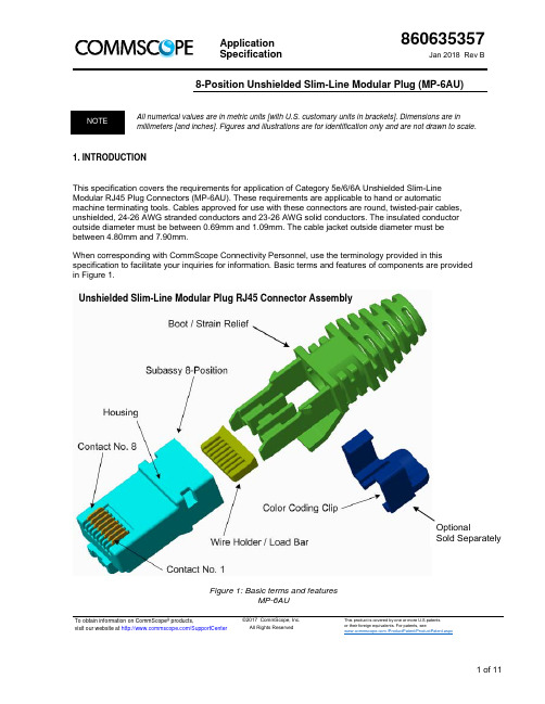
Application Specification860635357Jan 2018 Rev B8-Position Unshielded Slim-Line Modular Plug (MP-6AU)To obtain information on CommScope ® products,visit our website at /SupportCenter©2017 CommScope, Inc. All Rights ReservedThis product is covered by one or more U.S.patents or their foreign equivalents. For patents, see /ProductPatent/ProductPatent.aspxAll numerical values are in metric units [with U.S. customary units in brackets]. Dimensions are in millimeters [and inches]. Figures and illustrations are for identification only and are not drawn to scale.1. INTRODUCTIONThis specification covers the requirements for application of Category 5e/6/6A Unshielded Slim-Line Modular RJ45 Plug Connectors (MP-6AU). These requirements are applicable to hand or automaticmachine terminating tools. Cables approved for use with these connectors are round, twisted-pair cables, unshielded, 24-26 AWG stranded conductors and 23-26 AWG solid conductors. The insulated conductor outside diameter must be between 0.69mm and 1.09mm. The cable jacket outside diameter must be between 4.80mm and 7.90mm.When corresponding with CommScope Connectivity Personnel, use the terminology provided in thisspecification to facilitate your inquiries for information. Basic terms and features of components are provided in Figure 1.Figure 1: Basic terms and featuresMP-6AUUnshielded Slim-Line Modular Plug RJ45 Connector AssemblyOptionalSold Separately2. REFERENCE MATERIAL2.1. Revision SummaryThis paragraph is reserved for a revision summary of changes and additions made to this specification. The following changes were made for this revision:Removed references to discontinued tooling.2.2. Customer AssistanceReference Part Numbers 6-2843007 (Catalog No. MP-6AU-PLUG-A) and 6-2843008 (Catalog No. MP-6AU-PLUG-B) are representative numbers of 8-position Category 5e/6/6A Unshielded Slim-Line Modular RJ45 Plug Connectors. Use of these numbers will identify the product line and expedite your inquires through a service network established to help you obtain product and tooling information. Such information can be obtained through a local CommScope Connectivity Representative (Field Sales Engineer, Field Applications Engineer, etc.).2.3. DrawingsCustomer Drawings for specific products are available from the service network. The information contained in the Customer Drawings takes priority if there is a conflict with this specification or with any other technical documentation supplied by CommScope Connectivity.2.4. SpecificationsProduct Specification 108-131013 provides product performance requirements. Product Qualification Test Report 501-131013 provides test results.2.5. Instructional MaterialThe following list includes available instruction sheets (408-series) and customer manuals (409-series) that provide operation, maintenance, and repair of tooling. In addition, follow the instructions and procedures outlined in Paragraph 3.2 of this specification for product assembly procedures.Document Number Document Title408-4389 Crimp Height Gage 904170-1408-9767 Modular Plug Hand Tool Assembly X-231652-X.3. REQUIREMENTS3.1. StorageA. Ultraviolet LightProlonged exposure to ultraviolet light may deteriorate the chemical composition used in the connector components.B. Shelf LifeAll components products should remain in the shipping containers until ready for use to preventdamage. These products should be used on a first in, first out basis to avoid storage contamination.C. Chemical ExposureDo not store connector components near any chemicals listed below, as they may cause stresscorrosion cracking in the product.SulfurCompoundsCitratesPhosphatesAmmonia CitratesAlkaliesNitritesTartratesSulfurAminesNitritesCarbonatesWhere the above environmental conditions exist, phosphor-bronze contacts are recommended if available.3.2. CableA. Cable Specifications1. Cable Type: Round jacketed, Unshielded, four twisted pairs.2. Conductor Type:a. Stranded Conductor: 24-26 AWGb. Solid Conductor: 23-26 AWG3. Conductor Insulation Outside Diameter: 0.69mm -1.09mm [.027-.043] for any one conductor.See section 7 Ordering Guide.4. Cable Jacket Insulation Diameter: 4.80mm – 7.40mm [.189 - .291]. See section 7 OrderingGuide.5. Unshielded Type: With or without cable central filler3.3. Terminated Connector Requirements and ProcessCable Pair Arrangement: The arrangement of color-coded pairs within the cable jacket applicable to TIA/EIAT568B wiring and the termination procedures described in this specification is shown in Figure 3. Cable endA applies to one end of the cable and cable endB to the opposite end. For TIA/EIA T568A wiring ortermination of cables with pair arrangements other than TIA/EIA T568B, contact the responsibleCommScope Connectivity Engineering Department.3.4. Terminated Connector InstructionThis section provides instruction for assembly and terminated of twisted pairs cable to MP-6AU modularplug, see the following process steps below. Note that step 6 on which pairs to have no-twist and add-twistwithin plug boot manager section is only reference. Note that depending on the electrical characteristics ofthe customer twisted pair cable the no-twist and add-twist of what pair method maybe different then shownin step 6. Additionally, the position of the pairs in the pair manger described in steps 3 and 4 may alsoneed to be altered to achieve the ultimate performance. It is the responsibility of the user to determine the optimum twist and pair layout depending upon the cable being terminated.1.25 INCHCut away filler strip from end of cable jacket. Cut as close as you can to the edge of the cable jacket Strip cable jacket back to dimension 1.25 inch. Insert cable jacket and wire pairs into boot/ pair manager with Blue wire pair on top.On the reverse latch side; Orange , Green , and wire pairs are positioned as shown.On reverse latch side wire pairs; Orange , Blue , are positioned as shown. 03a04aOpposite end of cordage, position Green wire pair on top. Blue Pair on TopFront ViewPair on TopFront View011.25 inchesO WW 0506Slide wire pairs into load bar until wire insulationreaches ending point. Make sure wires are allthe way into load bar housing. 09 Push the plug housing over the load bar through the boot pair manger all the way until it latches to the boot. Terminate plug contacts to wire pairs with termination tool to seat the contacts.W Push cable jacket to dimension 0.25 +/- 0.02 inch. Cut wires to dimension 0.20 +/- 0.01 inch.10Vertical Walls3.4. Terminated Connector RequirementsFigure 2 shows a cutaway side view of a typical terminated plug and the required location of the plug contact. A visual check through the plastic plug housing and load bar should reveal whether the conductors are within the acceptable location.For optimum transmission performance (acceptable location), it is preferred that all conductors be fully inserted into the plug load bar housing with the ends of the conductors bottomed against the inside front surface of the plug load bar housing. For reliable electrical termination, the conductors must at least be inserted past the plug contact within the load bar housing.Proper crimp height can be inspected using an indicator with needle-point probes or equivalent. The crimp height shall be measured at the front of the contact as shown in Figure 16.Figure 23.5. Repair/ReplacementDamaged components must not be used. If a damaged component is evident, it must be replaced with a new one.4. QUALIFICATIONSThe Modular Plug Connectors are not required to be Listed or Recognized by Underwriters Laboratories Inc. (UL), or Certified to the Canadian Standards Association (CSA).5. TOOLINGThis section provides information on the hand tool to be used with these plugs.HAND TOOL (DOCUMENT) Hand Terminator HAND TOOL DIE SET ONLY X-231652-X (408-9767)1-853400-5Figure 3: ToolingModular Plug Die Set:MP-6AU Die Only (PINK DOT) 1-853400-5Modular Plug Hand Tool:Hand Tool with MP-6AU Die (PINK DOT) 3-231652-7Hand Tool with No Die 2-231652-05.1 TOOLING MODULE MODIFICATION, IF EXISTING PART NUMBERS BELOWThis section provides instruction for modification of existing dual terminating module with the following Part Numbers: [NOTE: Terminating equipment has been discontinued]Module 1-856196-1 comes with two Primary Stuffer strain relief blocks per below in Figure 19. Remove the two Primary Stuffer strain relief blocks from module and if require replace the two #8-32UNC socket cap screws with shorter length screws.Module 856196-2 comes with two Primary Stuffer strain relief blocks and two Secondary Stuffer strain relief blocks per below in Figure 4. Remove the two Primary Stuffer strain relief blocks and two Secondary Stuffer strain relief blocks from module and if require replace the two #8-32UNC socket cap screws with shorter length screws.Figure 4: Tooling6. VISUAL AIDFigure 5 shows typical applications of Modular Plug Connectors. These illustrations should be used by production personnel to ensure a correctly applied product. Applications which DO NOT appear correct should be inspected using the information in the preceding pages of this specification and in the instructional material shipped with the product or tooling.Figure 5: Visual Aid7. Ordering Information:MP-6AU Plug Housing with wire manager is ordered as a kit depending upon conductor diameter. MP-6AU-Boot is ordered separately based on cable diameter. See Figure 6, Both the Plug Housing/Wire Manager Kit and the Integrated Boots are sold in bags of 100.Figure 6: Visual AidCatalog NumberDescriptionConductor Insulation Diameter6-2843007-1 MP-6AU-Plug-A-1Plug Housing with 0.99 mmWire-Manager 1.09 mm-0.89 mm [0.043 in – 0.035 in] 6-2843008-1 MP-6AU-Plug-B-1Plug Housing with 0.79 mmWire-Manager0.89 mm - 0.69 mm [0.035 in – 0.027 in]Catalog NumberDescriptionCable Diameter2843018-3 MP-6AU-Boot-71-1 Integrated Boot and Manager, 7.1 mm 7.40 mm - 6.80 mm [0.291 in – 0.268 in] 2843020-3 MP-6AU-Boot-59-1 Integrated Boot and Manager, 5.9 mm 6.20 mm -5.60 mm [0.244 in – 0.220 in] 2843021-3 MP-6AU-Boot-54-1 Integrated Boot and Manager, 5.4 mm 5.70 mm - 5.10 mm [0.224 in – 0.201] 2843023-3MP-6AU-Boot-51-1Integrated Boot and Manager, 5.1 mm5.40 mm - 4.80 mm [0.212 in – 0.189 in]Figure 7:860635357Rev B 11 of 118. Plug Accessories (Sold Separately)8.1 Color Coding ClipFigure 8 shows typical applications of Modular Plug Connector with Color Coding Clip. The color coding clip simply snaps onto the plug boot in the field by the customer and is exchangeable, latch around the plug boot. The color clips is offered in bags of 50 and come in nine (9) different colors. After the color coding clip is latch onto the plug boot, make sure color clip latches are flush to plug boot surface on each side.Figure 8: Modular Plug MP-6AU and MP-6AU-Boot with Color Coding ClipMID Color ClipsBoot Compatibility2843022-1 MP-ColorClip-Almond-50 MP-6AU-Boot MP-BOOT-S-SL MP-5EU-Boot2843022-2 MP-ColorClip-Black-50 2843022-3 MP-ColorClip-White-50 2843022-4 MP-ColorClip-Gray-50 2843022-5 MP-ColorClip-Orange-50 2843022-6 MP-ColorClip-Blue-50 2843022-7 MP-ColorClip-Red-50 2843022-8 MP-ColorClip-Yellow-50 2843022-9MP-ColorClip-Green-50Figure 9:。
8用友T+薪资管理模块功能介绍

步骤2:期初录入-薪资期初余额
非1月启用薪资模块时,需要录入员工的期初累计数据,以便在启用月正确计算个税,此时无需补录以前 期间薪资数据
• 支持按各项累计项目分别录入期初 • 支持Excel导入期初数据
• 支持专项附加扣除数据智能化校验, 防止数据错输导致个税计算错误
注意:项目实施时需与客户确认是否需要统计一整年数据,如需要时则要在1月启用薪资管理模块并补录每月薪资核算单, 另先启用总账再启薪资管理时,薪资管理启用期间不能早于总账启用期间
步骤2:期初录入-薪资期初余额
企业薪资核算如不存在税后增项场景时,累计税前应发合计=累计应发合计,此时两列按相同数据录入/ 导入即可;如存在税后增项场景时,累计税前应发合计=所有参与应税所得额计算的税前增项的合计数, 累计应发合计=所税前增项合计数+税后增项合计数
• 累计税前应发合计影响后续个税的正 确计算
步骤1:基础设置-薪资项目
增减属性选择税前两项时项目需要参与累计应税所得计算,选择税后两项时则不参与,但参 与应发合计、实发合计的计算。
应用举例: • 税后增项(免征税收入) 有些项目属于免征税收入无需缴税,如按照 国家统一规定发给的补贴、津贴免纳个人所 得税,从企业、事业单位、国家机关、社会 团体提留的福利费或者工会经费中支付给个 人的生活补助费等,这些项目在计算应发合 计、实发合计时需要纳入,在计算税前应发 合计、应纳税所得额时需要剔除。 • 税后减项(税后扣款) 如员工租住公司宿舍,宿费需要在工资中扣 除时,此时在计算应发合计、实发合计时需 要纳入,在计算税前应发合计、应纳税所得 额时需要剔除。
• 薪资项目已做分类且后台根据分类自动 计算项目,不支持自定义分类
• 只能在基本项目下增加薪资项目,其他 分类禁止增加项目
K-AIH01 8通道带HART模拟量输入模块使用说明书

HOLLiAS MACS -K系列模块2014年5月B 版HOLLiAS MAC-K系列手册- K-AIH01 8通道带HART模拟量输入模块重要信息危险图标:表示存在风险,可能会导致人身伤害或设备损坏件。
警告图标:表示存在风险,可能会导致安全隐患。
提示图标:表示操作建议,例如,如何设定你的工程或者如何使用特定的功能。
目录1.概述 (1)2.接口说明 (3)2.1模块单元示意图 (3)2.2IO-BUS (4)2.3模块的防混淆设计 (6)2.4模块地址跳线 (7)2.5现场接口电路原理 (8)3.指示灯说明 (12)4.其他特殊功能说明 (14)4.1抗220V AC功能 (14)4.2二线制外供电功能 (15)4.3诊断功能 (16)4.4冗余功能 (18)5.工程应用 (19)5.1底座选型说明 (19)5.2应注意事项 (20)6.尺寸图 (21)7.技术指标 (21)K-AIH018通道带HART模拟量输入模块1.概述K-AIH01为K系列8通道模拟量通道隔离输入模块,支持Profibus-DP协议、HART协议。
测量范围0~22.7mA模拟信号(默认出厂量程4~20mA),同时与现场HART智能执行器进行通信,以实现现场仪表设备的参数设置、诊断和维护等功能。
可以按1:1冗余配置使用。
无需跳线就可以设置为配电或不配电工作方式,可以接二线制仪表或四线制仪表。
K-AIH01模块具备强大的过流过压保护功能,误接±30VDC和过电流都不会损坏。
同时,配合增强型底座还可以做到现场误接220V AC不损坏。
K-AIH01模块支持带点热插拔、支持冗余配置,具备完善断线、短路、超量程诊断功能,面板设计有丰富的LED指示灯,除指示模块电源、故障、通讯信息外,每个通道也有指示灯,可以方便指示各通道的断线、短路、超量程等信息。
K-AIH01模块每个通道可设置不同的滤波参数以适应不同的干扰现场。
可以根据工艺需要,配合主控制器的不同运算周期,组成可快可慢的控制回路。
K-AI01 8通道模拟量输入模块使用说明书
MACS‐K 系列模块
K‐AI01
8 通道模拟量输入模块使用说明书
通道 4 二线制外供电 24V+输出 NC 通道 5 电流输入正 通道 5 四线制电流输入负端 通道 5 二线制外供电 24V+输出 NC 通道 6 电流输入正 通道 6 四线制电流输入负端 通道 6 二线制外供电 24V+输出 NC 通道 7 电流输入正 通道 7 四线制电流输入负端 通道 7 二线制外供电 24V+输出 NC 8 通道电流输入正 通道 8 四线制电流输入负端 通道 8 二线制外供电 24V+输出 NC NC NC 测试端,现场电源+24V,禁止接线 测试端,现场电源地,禁止接线
第6页 共 20 页
通道 1
Байду номын сангаас
B1 C1 D1 A2
通道 2
B2 C2 D2 A3
通道 3
B3 C3 D3
通道 4
和利时公司版权所有
A4 B4
K-AI01
8 通道模拟量输入模块使用说明书
A/01
修订日期 2013-3-12
C4 D4 A5 通道 5 B5 C5 D5 A6 通道 6 B6 C6 D6 A7 通道 7 B7 C7 D7 A8 通道 8 B8 C8 D8 A 现场电源 B C D
图 1-3
模块单元安装位置图
2. 接口说明
2.1 模块单元示意图
K-AI01模块是否能正常通信、能正常处理数据,都跟模块接口有直接的关联。如图2-1所示为 K-AI01模块的外观接口示意图,图2-1中包括多功能总线电缆插头、现场信号接线端子、模块地址设 置开关和保险丝仓,下面将分别介绍各接口。
和利时公司版权所有
stc8 pca脉冲宽度 -回复

stc8 pca脉冲宽度-回复什么是STC8 PCA脉冲宽度?STC8是一款由STC公司推出的高性能单片机,而PCA(Pulse-Code Modulation)脉冲宽度调制是一种常见的数字调制技术。
将它们结合使用,就可以实现多种应用,例如控制电机速度、音频编码等。
在本文中,我们将详细介绍STC8 PCA脉冲宽度调制的原理和实现方法。
首先,我们需要理解PCA脉冲宽度调制的基本原理。
PCA是一种将模拟信号转换为数字信号的技术。
它通过对一个周期的脉冲宽度进行编码,将模拟信号的幅度信息转换为数字信号的占空比。
这样,我们可以用数字信号来模拟模拟信号的变化,从而实现信号的数字传输和处理。
在STC8单片机中,PCA模块是其内部集成的一个特殊功能模块。
它能够通过硬件自动产生PWM脉冲,并且具有多种工作模式和功能。
它的主要工作原理是通过选择不同的时钟源和计数器配置来产生不同频率和占空比的PWM波形。
STC8 PCA模块具有较高的精度和稳定性,能够满足多种应用的需求。
下面,我们将详细介绍STC8 PCA脉冲宽度调制的步骤。
步骤一:使能PCA模块首先,在使用PCA脉冲宽度调制之前,需要使能STC8单片机的PCA模块。
可以通过设置相应的寄存器来实现使能操作。
具体的操作步骤可以参考STC8的用户手册或者开发工具的相关文档。
步骤二:选择时钟源在使用PCA模块进行脉冲宽度调制之前,需要选择适当的时钟源来提供时钟信号。
STC8单片机的PCA模块可以支持多种时钟源,如系统时钟、外部时钟等。
选择不同的时钟源可以实现不同的PWM波形频率和精度。
选择合适的时钟源需要根据具体的应用需求进行。
步骤三:配置计数器和比较器在开始使用PCA模块进行脉冲宽度调制之前,还需要配置计数器和比较器的参数。
计数器决定了PWM波形的周期,比较器决定了PWM波形的占空比。
STC8单片机的PCA模块具有多个可配置的计数器和比较器,可以通过设置相应的寄存器来完成配置。
K-AO01 8通道模拟量输出模块使用说明书

HOLLiAS MACS -K系列模块2014年5月B版HOLLiAS MAC-K系列手册- K-AO01 8通道模拟量输出模块重要信息危险图标:表示存在风险,可能会导致人身伤害或设备损坏件。
警告图标:表示存在风险,可能会导致安全隐患。
提示图标:表示操作建议,例如,如何设定你的工程或者如何使用特定的功能。
目录1.概述 (1)2.接口说明 (3)2.1模块单元示意图 (3)2.2现场信号接线说明 (4)2.3模块地址跳线 (7)2.4模块的防混淆设计 (7)2.5IO-BUS (7)3.状态灯说明 (7)4.其他特殊功能说明 (9)4.1抗AC220V功能 (9)4.2诊断功能 (9)4.3输出故障安全 (10)4.4冗余功能 (11)5.工程应用 (12)5.1底座选型说明 (12)5.2应用注意事项 (13)6.尺寸图 (14)7.技术指标 (14)K-AO018通道模拟量输出模块1.概述K-AO01为K系列硬件8通道模拟量通道隔离输出模块,最大输出范围0~22.7mA模拟信号(默认出厂量程4~20mA)。
K-AO01可按1:1冗余配置使用,实现冗余AO输出,最大增加系统的可用性。
K-AO01模块具备强大的过流过压保护功能,误接±30VDC和过电流都不会损坏。
同时,配合增强型底座还可以做到现场误接AC220V不损坏。
K-AO01模块具备完善故障硬件诊断功能,面板设计有丰富的LED指示灯,除可显示模块电源、故障、通讯信息外,每个通道也有指示灯,可以方便指示各通道的诊断信息。
K-AO01模块每个输出通道单独进行故障输出组态,可在主控模块通讯中断或发生通道输出故障时,保持上一拍数据或输出预设安全值,以适应不同的现场需求。
如图1-1(a), (b), (c)所示,分别为模块非冗余配置和冗余配置的外观结构图。
(a)非冗余接线端子底座(b)非冗余DB37底座(c)冗余底座图1-1 K-AO01模块非冗余底座和冗余底座示意图完整的模块单元在系统机柜中的安装位置如图1-2所示。
STM8教程-第十三章 STM8S207 定时器模块及其应用实例
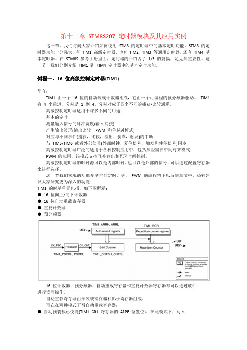
第十三章STM8S207 定时器模块及其应用实例这一节,我们将向大家介绍如何使用STM8 的定时器中的基本定时功能,STM8 的定时器功能十分强大,有TIM1 高级定时器,也有TIM2、TIM3 等通用定时器,还有TIM4 基本定时器。
在STM8S 参考手册里面,定时器的介绍占了1/3 的篇幅,足见其重要性。
这一节,我们分别介绍TIM1 到TIM4 定时器中的基本定时功能。
例程一、16 位高级控制定时器(TIM1)简介:TIM1 由一个16 位的自动装载计数器组成,它由一个可编程的预分频器驱动。
TIM1 有4 个通道,分别是1 到4。
分别对应于四个不同的捕获/比较通道。
高级控制定时器适用于许多不同的用途:基本的定时测量输入信号的脉冲宽度(输入捕获)产生输出波形(输出比较,PWM 和单脉冲模式)对应与不同事件(捕获,比较,溢出,刹车,触发)的中断与TIM5/TIM6 或者外部信号(外部时钟,复位信号,触发和使能信号)同步高级控制定时器广泛的适用于各种控制应用中,包括那些需要中间对齐模式PWM 的应用,该模式支持互补输出和死区时间控制。
高级控制定时器的时钟源可以是内部时钟,也可以是外部的信号,可以通过配置寄存器来进行选择。
这一节我们实现的功能是基本的定时,关于PWM 的编程留下以后的章节中。
还有建议大家研究更为深入的功能TIM1 的时基单元包括,如下图所示:●16 位向上/向下计数器●16 位自动重载寄存器●重复计数器●预分频器16 位计数器,预分频器,自动重载寄存器和重复计数器寄存器都可以通过软件进行读写操作。
自动重载寄存器由预装载寄存器和影子寄存器组成。
可在在两种模式下写自动重载寄存器:●自动预装载已使能(TIM1_CR1 寄存器的ARPE 位置位)。
在此模式下,写入自动重载寄存器的数据将被保存在预装载寄存器中,并在下一个更新事件(UEV)时传送到影子寄存器。
●自动预装载已禁止(TIM1_CR1 寄存器的ARPE 位清除)。
道路CAD(第8模块三维建模基础及应用)
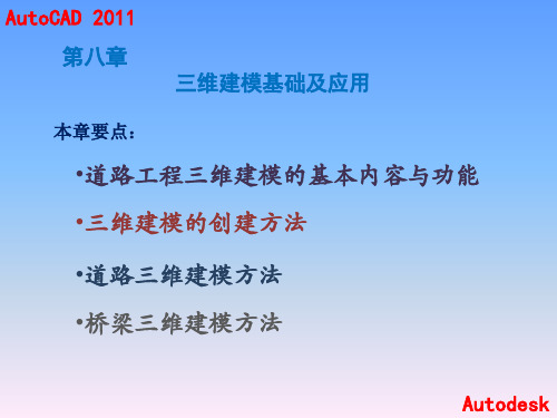
AutoCAD 2011
8.1.2 道路工程三维建模的基本功能
道路工程三维建模:创建基本三维模型及用它 们组合成实际的工程结构模型两个部分
基本三维面是一种表面模型:三维平面、三 维曲面两大类
三维物体的构造模型主要有: 线框模型 表面模型 实体模型
Autodesk
AutoCAD 2011
AutoCAD 2011
3.绘制楔形体(ai_Wedge)表面 命令:ai_wedge(回车) AutoCAD将出现以下提示,要求用户逐步确定楔形体的尺寸; • 指定长角点给楔体表面:(给定楔形体长度) • 指定长度给楔体表面:(给定楔形体长度) • 指定楔体的表面宽度:(给定楔形体宽度) • 指定高度给楔体表面:(给定楔形体高度) • 指定楔体表面绕Z轴旋转的角度:(输入楔形体绕Z轴的旋转角度)。 输入参数后,楔形体便绘制出来了,如图8-8(a)所示旋转角度为90º。
Autodesk
AutoCAD 2011
4.绘制圆顶(ai_Dome)表面 该选项绘制圆球的顶面,类似一个球盖。选择这一选项,AutoCAD将出 现以下提示。 命令:ai_dome(回车) •指定中心点给上半球面:(输入圆顶表面中心得坐标) •指定上半球的半径或[直径D]:(指定圆顶的直径或半经) •输入曲面的经线数目给上半球面〈16〉:(输入圆顶面在经度方向的 网格数) •输入曲面的纬度数目给上半球面〈8〉:(输入圆顶面在纬度方向的网 格数),如图8-8(b)所示。
②“四面体”选项,绘制三棱锥或三棱台表面。选择该选项,AutoCAD将出现以 下提示:
指定四面体表面的顶点或[顶面(T)]: 默认项为:“顶点”,用户输入一个顶点,绘制一个三棱台表面,如图8-7(d) 所示;“顶面”选项,则要求用户输入三个点,创建一个三棱锥体表面,如图8-7 (e)所示。
- 1、下载文档前请自行甄别文档内容的完整性,平台不提供额外的编辑、内容补充、找答案等附加服务。
- 2、"仅部分预览"的文档,不可在线预览部分如存在完整性等问题,可反馈申请退款(可完整预览的文档不适用该条件!)。
- 3、如文档侵犯您的权益,请联系客服反馈,我们会尽快为您处理(人工客服工作时间:9:00-18:30)。
1、FX2N-4AD特殊模块简介 2、FX2N-4AD安装使用 3、FX2N-4AD缓冲存贮器的分配 4、FX2N-4AD的编程举例 5、FX2N-1PG定位模块简介 6、FX2N-1PG缓冲存贮器的分配 7、FX2N-1PG的编程举例
FX2N-4AD模块简介
FX2N-4AD模拟量特殊模块有四个输入通道,输入通 道接受模拟信号并转换为数字量,称为A/D转换。 FX2N-4AD最大 值为12位。 输入输出的电压电流的选择通过用户接线完成,可选 用-10~+10VDC(精度为:5mV),4~20mA,-20~ +20mA(精度为:20uA) FX2N-4AD与FX2N基本单元间通过缓冲区交换数据, FX2N-4AD有条不紊2个缓冲区(每一个有16位)。 FX2N-4AD占用FX扩展总线I/O8点,这8点分配为输 入输出都可以。FX2N-4AD消耗FX基本单元或有源扩 展单元40mA电流。
FX2N-4AD的安装使用
模拟量的对应值
FX2N-4AD缓冲存贮器的分配
FX 2N-4AD编程举例
FX 2N-4AD编程举例
增益/偏置设置
软件设置 硬件设置 先将使增益/偏置设置允许 1.接好PLC系统,通电(run or stop) 2.将FX2N-4AD方式开关旋至通道1 3.将偏置模拟信号与相应输入通道接线 端相连(偏置值用电压/电流表测定,调整到 需要的数值) 4.按下偏置按钮(offset)一次,偏置值的数字量(由输入 模拟量转换而成)就存入到相应的缓冲器
FX 2N-4AD编程举例
5.调整输入模拟量信号,直到达到相应的增益值 6.按增益(GAIN)按钮一次,增益数字量就存入4AD 相应的缓冲器 7.重复3、4、5、6,调整其余通道增益、偏置设置 8.各通道设置完毕后,将FX2N-4AD方式开关旋 至就绪(READY)位置,
FX2N-1PG定位模块简介
FX2N-1PG的缓冲存贮器分配
FX2N-1PG编程举例
1》原点回归操作(定义原点为“0“)
2》JOG运行
3》作1000mm定位操作
1PG举例
1PG举例
1PG举例Hale Waihona Puke 1PG举例1PG举例
1PG举例
1PG举例
第八单元完