AlnkxruLM386中文资料
AR3PJ-M386A;AR3PD-M386A;AR3PG-M386A;AR3PD-M387A;AR3PG-M387A;中文规格书,Datasheet资料

Document Number: 89332For technical questions within your region, please contact one of the following: Fast Switching Avalanche Surface Mount RectifiersAR3PD, AR3PG, AR3PJVishay General SemiconductorTYPICAL APPLICATIONSFor use in lighting, fast switching rectification of power supplies, inverters, converters, and freewheeling diodes for consumer, automotive, and telecommunication.FEATURES•Very low profile - typical height of 1.1 mm •Ideal for automated placement •Glass passivated chip junction •Fast reverse recovery time•Controlled avalanche characteristics •Low leakage current•High forward surge capability•Meets MSL level 1, per J-STD-020, LF maximum peak of 260 °C•AEC-Q101 qualified•Compliant to RoHS Directive 2002/95/EC and in accordance to WEEE 2002/96/EC•Halogen-free according to IEC 61249-2-21 definitionMECHANICAL DATACase: TO-277A (SMPC)Molding compound meets UL 94 V-0 flammability rating Base P/N-M3 - halogen-free, RoHS compliant, and commercial gradeBase P/NHM3 - halogen-free, RoHS compliant, and automotive gradeTerminals: Matte tin plated leads, solderable per J-STD-002 and JESD 22-B102M3 suffix meets JESD 201 class 1A whisker test, HM3 suffix meets JESD 201 class 2 whisker testNotes(1)Mounted on 14 mm x 14 mm pad areas, 1 oz. FR4 PCB (2)Free air, mounted on recommended pad areaPRIMARY CHARACTERISTICSI F(AV) 3.0 AV RRM 200 V, 400 V, 600 VI FSM 50 A t rr 140 ns E AS20 mJ V F at I F = 3.0 A1.04 V T J max.175 °CTO-277A (S MPC)Anode 1Anode 2CathodeK K21e S MP® S eriesMAXIMUM RATINGS (T A = 25°C unless otherwise noted)PARAMETER SYMBOLAR3PD AR3PG AR3PJ UNITDevice marking codeAR3D AR3G AR3J Maximum repetitive peak reverse voltage V RRM 200400600V Maximum DC forward current (fig. 1)I F (1) 3.0A I F (2) 1.8Peak forward surge current 10 ms single half sine-wave superimposed on rated loadI FSM 50A Non-repetitive avalance energy at T J = 25 °CI AS = 2.5 A max.E AS 20mJ I AS = 1.0 A typ.30Operating junction and storage temperature range T J , T STG - 55 to + 175°C For technical questions within your region, please contact one of the following:Document Number: 89332AR3PD, AR3PG, AR3PJVishay General SemiconductorNotes(1)Pulse test: 300 μs pulse width, 1 % duty cycle (2)Pulse test: Pulse width ≤ 40 msNotes(1)Free air, mounted on recommended PCB 1 oz. pad are; thermal resistance R θJA - junction to ambient (2)Units mounted on PCB with 14 mm x 14 mm copper pad areas; R θJM - junction to mountNote(1)AEC-Q101 qualifiedELECTRICAL CHARACTERISTICS (T A = 25°C unless otherwise noted)PARAMETERTEST CONDITIONS SYMBOL TYP.MAX.UNIT Instantaneous forward voltageI F = 3.0 AT A = 25 °C V F (1)1.24 1.6VT A = 125 °C 1.04 1.20Reverse currentRated V R T A = 25 °C I R (2)0.3310μA T A = 125 °C44250Maximum reverse recovery time I F = 0.5 A, I R = 1.0 A,I rr = 0.25 At rr 122140ns Typical junction capacitance per diode Rated V R = 4.0 V, 1 MHzC J44-pFTHERMAL CHARACTERISTICS (T A = 25°C unless otherwise noted)PARAMETERSYMBOL AR3PDAR3PG AR3PJUNIT Typical thermal resistanceR θJA (1)85°C/WR θJM (2)5ORDERING INFORMATION (Example)PREFERRED P/N UNIT WEIGHT (g)PREFERRED PACKAGE CODEBASE QUANTITYDELIVERY MODEAR3PJ-M3/86A 0.1086A 15007" diameter plastic tape and reel AR3PJ-M3/87A 0.1087A 650013" diameter plastic tape and reel AR3PJHM3/86A (1)0.1086A 15007" diameter plastic tape and reel AR3PJHM3/86A (1)0.1087A650013" diameter plastic tape and reelAR3PD, AR3PG, AR3PJVishay General SemiconductorRATINGS AND CHARACTERISTICS CURVES(T A = 25 °C unless otherwise noted)Fig. 1 - Maximum Forward Current Derating Curve Fig. 2 - Average Power Loss CharacteristicsFig. 3 - Typical Instantaneous Forward Characteristics Fig. 4 - Typical Reverse Leakage Characteristics Fig. 5 - Typical Junction CapacitanceFig. 6 - Typical Transient Thermal ImpedanceDocument Number: 89332For technical questions within your region, please contact one of the following:AR3PD, AR3PG, AR3PJVishay General SemiconductorPACKAGE OUTLINE DIMENSIONS in inches (millimeters) For technical questions within your region, please contact one of the following:Document Number: 89332Legal Disclaimer Notice VishayDisclaimerALL PRODU CT, PRODU CT SPECIFICATIONS AND DATA ARE SU BJECT TO CHANGE WITHOU T NOTICE TO IMPROVE RELIABILITY, FUNCTION OR DESIGN OR OTHERWISE.Vishay Intertechnology, Inc., its affiliates, agents, and employees, and all persons acting on its or their behalf (collectively,“Vishay”), disclaim any and all liability for any errors, inaccuracies or incompleteness contained in any datasheet or in any other disclosure relating to any product.Vishay makes no warranty, representation or guarantee regarding the suitability of the products for any particular purpose or the continuing production of any product. To the maximum extent permitted by applicable law, Vishay disclaims (i) any and all liability arising out of the application or use of any product, (ii) any and all liability, including without limitation special, consequential or incidental damages, and (iii) any and all implied warranties, including warranties of fitness for particular purpose, non-infringement and merchantability.Statements regarding the suitability of products for certain types of applications are based on Vishay’s knowledge of typical requirements that are often placed on Vishay products in generic applications. Such statements are not binding statements about the suitability of products for a particular application. It is the customer’s responsibility to validate that a particular product with the properties described in the product specification is suitable for use in a particular application. Parameters provided in datasheets and/or specifications may vary in different applications and performance may vary over time. All operating parameters, including typical parameters, must be validated for each customer application by the customer’s technical experts. Product specifications do not expand or otherwise modify Vishay’s terms and conditions of purchase, including but not limited to the warranty expressed therein.Except as expressly indicated in writing, Vishay products are not designed for use in medical, life-saving, or life-sustaining applications or for any other application in which the failure of the Vishay product could result in personal injury or death. Customers using or selling Vishay products not expressly indicated for use in such applications do so at their own risk and agree to fully indemnify and hold Vishay and its distributors harmless from and against any and all claims, liabilities, expenses and damages arising or resulting in connection with such use or sale, including attorneys fees, even if such claim alleges that Vishay or its distributor was negligent regarding the design or manufacture of the part. Please contact authorized Vishay personnel to obtain written terms and conditions regarding products designed for such applications.No license, express or implied, by estoppel or otherwise, to any intellectual property rights is granted by this document or by any conduct of Vishay. Product names and markings noted herein may be trademarks of their respective owners.Material Category PolicyVishay Intertechnology, Inc. hereb y certifies that all its products that are identified as RoHS-Compliant fulfill the definitions and restrictions defined under Directive 2011/65/EU of The European Parliament and of the Council of June 8, 2011 on the restriction of the use of certain hazardous substances in electrical and electronic equipment (EEE) - recast, unless otherwise specified as non-compliant.Please note that some Vishay documentation may still make reference to RoHS Directive 2002/95/EC. We confirm that all the products identified as being compliant to Directive 2002/95/EC conform to Directive 2011/65/EU.Revision: 12-Mar-121Document Number: 91000分销商库存信息:VISHAY-GENERAL-SEMICONDUCTORAR3PJ-M3/86A AR3PD-M3/86A AR3PG-M3/86A AR3PD-M3/87A AR3PG-M3/87A AR3PJ-M3/87A AR3PDHM3/87A AR3PGHM3/87A AR3PJHM3/87A AR3PDHM3/86A AR3PGHM3/86A AR3PJHM3/86A。
第五讲模块5集成功放LM386

二、传声器的认识:将声音转换成音频电信号的声电器件 或称为“话筒”“麦克风”“微音器” 1、传声器的分类方法很多,主要有以下几个。 ①按换能原理分类,有电动式传声器(如动圈式传声器、铝带式传声器等)、 电容式传声器(其中包括驻极体式传声器)、电磁式传声器、半导体式传声 器和压电式传声器(晶体传声器、陶瓷传声器、压电高聚合物式传声器)。 ②按指向性图分类,有无指向传声器(又称全指向传声器)、双向传声器 (又称8字形指向性传声器)和心形传卢器、超心形传声器、超指向传声器 (它们又称为单向传声器)。 ③按使用场合分类,有普通传声器、立体声传声器、近讲传声器、佩戴式传 声器、无线传声器和测量用传声器等。 2、传声器的选择: 传声器的种类很多,要根据场合和要求进行合理选择。 ①要求可靠的,应选动圈式。 ②要求音质清脆的,应选电容式传声器。 ③注意电源的要求,有的直接接在电缆线上,有特殊的(48V直流)。 ④根据传声器的选场合,例如:体积大小、有无传输线、抗噪强度等。噪声 大的场所应选抗噪音强的; ⑤注意传声器的技术指标选择,如:指向性、灵敏性、最大承受的声压。 ⑥注意传声器的特点及使用范围。 3、传声器的保养:
通入信号电流即可振动发音。带状高音扬声器的阻抗非常小, 与放大器和分频网络连接时,必须用匹配变压器。 ⑥薄片扬声器。 该种扬声器的振膜是用耐高温的高分子薄膜形成的,音圈 装在或印刷在高分子振膜上。将印刷有音圈的高分子振膜置 于特殊形状磁体构成的磁场中,就可做成薄片型扬声器。此 种扬声器的音圈导线电阻可设计成几Ω,可不用匹配变压器, 同时其输入容量大。在音质方面,它和带状扬声器一样,不 失真的自然声音感可延伸到较高的频段。 3)按用途分类 ①全频带扬声器。它能够同时覆盖高、低频段,其振膜振 动可产生从低音到高音的全频带声音。在全频带扬声器中, 有单纸盆的全频带扬声器、双纸盆型和同轴型扬声器。双纸 盆和单纸盆扬声器都是整体结构。同轴型扬声器是把两个扬 声器做在一起构成一种多声道器件。
LM386中文资料
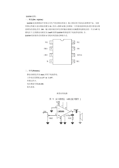
LM386说明:
一、概述(Des cription):
LM386是美国国家半导体公司生产的音频功率放大器,主要应用于低电压消费类产品。
为使外围元件最少,电压增益内置为20。
但在1脚和8脚之间增加一只外接电阻和电容,便可将电压增益调为任意值,直至200。
输入端以地位参考,同时输出端被自动偏置到电源电压的一半,在6V电源电压下,它的静态功耗仅为24mW,使得LM386特别适用于电池供电的场合。
LM386的封装形式有塑封8引线双列直插式和贴片式。
二、特性(Features):
静态功耗低,约为4mA,可用于电池供电。
工作电压范围宽,4-12V or 5-18V。
外围元件少。
电压增益可调,20-200。
低失真度。
典型应用电路。
(完整word版)Multisim中LM386构建所需的LM386.sym和LM386.cir

Multisim中LM386构建所需的LM386。
sym和LM386.cir 将以下内容粘贴至文本文档,另存为LM386.sym 即可<?xml version=”1.0"?><DrDoc Type=”BaseSymbolDocument"〉<LrsArr Type=”PtrArray” S="3”〉<I0 Type="LayerInfo" LN="Border" D="0” Hd=”0" V="1" A="0”〉〈DS Type=”ObjectsList” LS="1"〉〈I0 Type="B oundaryBox” Sel="0” Vis=”1" CBH=”1” PFC="—1" PW=”0" PS="5” BS="1” BC=”—1”>〈PtA Type="PtrArray" S="2”><I0 Type="Point” X=”45" Y="45"/〉<I1 Type=”Point” X="135” Y=”135”/></PtA〉</I0>〈/DS></I0>〈I1 Type=”LayerInfo” LN=”Pins” D="0" Hd="0” V="1" A=”0">〈DS Type="ObjectsList" LS="8"〉〈I0 Type="Pin” PShp="0" PTp="4” BusPin=”0” InternalPin="0" PLS=”4” PL="1” PCSE=”1" Sel="0” Vis=”1” CBH=”0” PFC=”-1” PW="0” PS=”0" BS=”1” BC="-1”>〈PtA Type="PtrArray" S=”0”/〉<PD Type="Group" DCR="0" Sel=”0” Vis="1” CBH=”0” PFC=”-1" PW=”0” PS="0” BS=”1” BC="-1">〈PtA Type="PtrArray" S=”2"〉〈I0 Type="Point" X=”63" Y="45”/><I1 Type=”Point" X=”63” Y="27”/〉〈/PtA〉〈OL Type=”ObjectsList” LS="1”〉<I0 Type=”Line" Sel="0” Vis="1" CBH="0” PFC="—1” PW=”0" PS=”0" BS=”1" BC="-1”>〈PtA Type="PtrArray” S="2”〉〈I0 Type="Point" X=”63” Y=”45”/><I1 Type="Point” X="63" Y=”27"/〉</PtA></I0>〈/OL>〈/PD>〈PNaT Type=”PinNameText" PNaTO="4" PNaTLS="0” Txt=”Vs" H="7" W=”0" E="900” O="900” Wg=”400" I="0” U=”0” SO=”0" CS=”0” OP="3” CP=”2" Q="1" PAF=”49" LTP=”0” KeepCurrentFont=”1” FN="Courier New” Sel=”0” Vis=”0” CBH="1" PFC=”—1” PW="0” PS=”0” BS="1” BC="-1"〉<PtA Type="PtrArray” S=”1"〉〈I0 Type=”Point” X=”63" Y=”51"/></PtA></PNaT>〈CTSP Type=”Point” X="63” Y="45”/>〈WCP Type=”WireConnectionPoint" X="63" Y="27”/>〈PNuT Type=”PinNumberText” PNuTO=”4" PNuTLS=”2” Txt="##" H="7" W=”0" E="0” O=”0” Wg=”400" I=”0" U="0” SO=”0" CS="0" OP=”3” CP="2" Q="1” PAF=”49"LTP=”0" KeepCurrentFont=”1" FN="Courier New” Sel="0" Vis=”1" CBH=”1” PFC=”—1” PW="0” PS="0” BS=”1” B C="-1">〈PtA Type=”PtrArray” S=”1"><I0 Type=”Point" X=”64” Y="41"/></PtA></PNuT>〈/I0><I1 Type=”Pin" PShp="0" PTp="4” BusPin="0” InternalPin=”0" PLS=”4” PL=”1” PCSE="1” Sel="0" Vis=”1” CBH=”0” PFC="—1” PW="0” PS="0” BS=”1” BC="-1”><PtA Type=”PtrArray"S=”0”/><PD Type="Group” DCR="0” Sel="0” Vis="1" CBH="0" PFC=”—1" PW=”0” PS="0” BS="1” BC="-1"〉<PtA Type=”PtrArray" S="2"〉〈I0 Type=”Point” X="90” Y=”45”/〉<I1 Type=”Point” X="90" Y="27"/〉</PtA><OL Type="ObjectsList” LS="1"〉<I0 Type=”Line” Sel="0" Vis="1" CBH=”0” PFC=”—1" PW="0” PS="0" BS="1" BC="-1”>〈PtA Type=”PtrArray” S="2">〈I0 Type="Point” X="90” Y="45”/〉<I1 Type=”Point" X="90" Y=”27"/〉〈/PtA>〈/I0></OL></PD〉〈PNaT Type="PinNameText” PNaTO="4” PNaTLS="0" Txt=”Gain1” H=”7" W="0" E=”900” O="900" Wg=”400” I="0" U="0” SO="0" CS=”0” OP="3" CP="2" Q=”1” PAF="49” LTP="0” KeepCurrentFont=”1” FN="Courier New” Sel="0” Vis="0" CBH="1" PFC=”—1" PW=”0” PS="0” BS=”1" BC=”—1”〉〈PtA Type="PtrArray" S="1”〉<I0 Type="Point” X="90" Y=”51”/>〈/PtA〉</PNaT〉〈CTSP T ype="Point" X=”90” Y="45”/〉〈WCP Type="WireConnectionPoint" X="90" Y=”27”/〉〈PNuT Type=”PinNumberText” PNuTO="4" PNuTLS="2" Txt=”##" H=”7” W="0" E=”0” O=”0” Wg=”400" I="0" U=”0" SO="0” CS=”0" OP="3" CP=”2" Q="1" PAF=”49" LTP=”0" KeepCurrentFont=”1" FN=”Courier New" Sel="0" Vis=”1" CBH="1" PFC=”—1” PW=”0” PS="0" BS="1” BC=”-1”>〈PtA Type="PtrArray” S="1”><I0 Type=”Point” X=”91" Y=”41”/></PtA></PNuT>〈/I1〉〈I2 Type=”Pin" PShp=”0" PTp=”4" BusPin="0” InternalPin=”0" PLS=”4" PL=”1” PCSE="1” Sel="0" Vis="1" CBH="0” PFC=”-1” PW=”0" PS=”0" BS=”1" BC=”-1”>〈PtA Type="PtrArray” S="0"/〉〈PD Type="Group" DCR="0” Sel=”0” Vis=”1” CBH=”0” PFC=”—1" PW="0” PS=”0"BS="1” BC="-1”><PtA Type="PtrArray” S=”2”><I0 Type=”Point" X="117” Y="45"/〉<I1 Type="Point" X=”117" Y="27”/>〈/PtA><OL Type=”ObjectsList” LS="1”〉〈I0 Type=”Line" Sel=”0” Vis=”1” CBH="0" PFC=”—1” PW="0” PS="0” BS="1" BC="—1"><PtA Type="PtrArray" S="2”>〈I0 Type="Point" X="117” Y="45"/><I1 Type="Point” X=”117" Y=”27”/></PtA>〈/I0>〈/OL〉〈/PD>〈PNaT Type=”PinNameText" PNaTO=”4” PNaTLS="0" Txt="Gain8” H=”7" W=”0” E=”900" O="900" Wg=”400" I=”0” U="0" SO="0” CS="0” OP="3" CP="2" Q=”1” PAF=”49" LTP="0” KeepCurrentFont=”1" FN="Courier New" Sel=”0” Vis=”0" CBH="1” PFC="—1” PW="0” PS="0” BS="1” BC=”—1”><PtA Type="Ptr Array" S=”1"〉<I0 Type="Point" X=”117” Y="51”/>〈/PtA></PNaT〉<CTSP Type=”Point" X=”117” Y=”45"/〉〈WCP Type=”WireConnectionPoint" X=”117” Y="27”/>〈PNuT Type=”PinNumberText" PNuTO="4" PNuTLS=”2" Txt=”##” H=”7" W=”0” E="0” O=”0" Wg="400” I="0" U="0” SO=”0"CS=”0" OP="3” CP=”2” Q=”1” PAF=”49” LTP=”0” KeepCurrentFont=”1" FN=”Courier New" Sel=”0" Vis="1” CBH=”1” PFC="-1” PW="0” PS=”0" BS="1" BC=”-1”〉<PtA Type="PtrArray" S="1"><I0 Type=”Point" X=”118” Y=”41”/〉〈/PtA></PNuT></I2〉<I3 Type=”Pin” PShp=”0" PTp="4” BusPin=”0” InternalPin="0” PLS="1” PL=”1” PCSE=”1" Sel="0" Vis="1" CBH=”0” PFC=”-1" PW=”0” PS="0" BS=”1" BC=”—1"><PtA Type=”PtrArray" S=”0"/>〈PD Type=”Group” DCR=”0" Sel="0" Vis=”1” CBH=”0" PFC="-1" PW=”0” PS=”0" BS=”1" BC="-1"><PtA Type=”PtrArray" S=”2"〉<I0 Type="Point" X="135” Y=”90"/〉〈I1 Type="Point” X="153" Y=”90”/>〈/PtA><OL Type="ObjectsList" LS=”1">〈I0 Type=”Line" Sel=”0" Vis=”1” CBH="0” PFC=”—1" PW="0" PS=”0" BS="1" BC=”—1”〉<PtA Type="PtrArray” S="2”>〈I0 Type=”Point” X="135" Y="90”/>〈I1 Type="Point" X="153" Y=”90”/〉</PtA>〈/I0〉</OL></PD>〈PNaT Type="PinNameText" PNaTO="1" PNaTLS="0” Txt=”Vout” H=”7" W=”0" E="0” O="0” Wg=”400” I="0” U=”0" SO=”0" CS="0” OP=”3” CP="2” Q="1” PAF=”49” LTP=”0” KeepCurrentFont=”1" FN=”Courier New” Sel=”0” Vis="0" CBH="1" PFC=”-1” PW=”0" PS="0” BS="1" BC=”—1"〉<PtA Type="PtrArray" S=”1"〉<I0 Type=”Point” X=”129" Y=”90"/〉〈/PtA>〈/PNaT>〈CTSP Type=”Point” X="135” Y=”90"/〉<WCP Type="WireConnectionPoint" X="153” Y="90"/><PNuT Type="PinNumberText" PNuTO=”1" PNuTLS="2” Txt=”##” H="7" W=”0” E=”0” O="0” Wg="400” I="0” U="0" SO="0” CS="0” OP="3” CP=”2" Q=”1" PAF="49” LTP=”0" KeepCurrentFont=”1" FN="Courier New" Sel="0" Vis=”1" CBH=”1” PFC=”—1" PW="0" PS="0" BS="1” BC=”-1"〉<PtA Type="PtrArray” S=”1"〉<I0 Type="Point” X="139” Y=”91”/〉〈/PtA〉</PNuT〉</I3>〈I4 Type=”Pin” PShp="0" PTp="4” BusPin="0” InternalPin=”0" PLS=”3” PL="1” PCSE="1" Sel=”0” Vis="1” CBH="0" PFC=”—1” PW="0" PS=”0” BS="1" BC="-1">〈PtA Type="PtrArray" S=”0”/〉<PD Type="Group" DCR=”0" Sel="0” Vis=”1” CBH=”0" PFC=”-1” PW="0" PS=”0" BS="1” BC="-1"〉〈PtA Type=”PtrArray” S="2"〉<I0 Type=”Point" X="45" Y=”63”/><I1 Type="Point" X="27” Y="63"/〉〈/PtA>〈OL Type=”ObjectsList” LS="1">〈I0 Type="Line” Sel="0" Vis=”1" CBH=”0” PFC="-1” PW=”0” PS=”0” BS=”1” BC="—1">〈PtA Type=”PtrArray” S=”2"〉〈I0 Type=”Point” X=”45" Y="63"/〉<I1 Type="Point” X=”27” Y=”63”/〉〈/PtA〉〈/I0〉〈/OL>〈/PD〉〈PNaT Type="PinNameText” PNaTO=”3” PNaTLS="0” Txt=”-IN” H="7” W="0" E=”0" O=”0” Wg=”400” I="0” U="0” SO=”0” CS=”0” OP=”3" CP="2" Q=”1" PAF="49" LTP="0” KeepCurrentFont="1” FN="Courier New" Sel=”0” Vis="0" CBH="1" PFC="-1” PW="0" PS="0” BS="1” BC="—1"〉〈PtA Type="PtrArray” S=”1”〉<I0 Type="Point” X="51” Y=”63"/></PtA>〈/PNaT>〈CTSP Type=”Point" X=”45” Y="63"/><WCP Type=”WireConnectionPoint” X=”27” Y="63”/>〈PNuT Type=”PinNumberText" PNuTO="3" PNuTLS="2" Txt="##” H="7” W=”0" E="0" O="0” Wg=”400" I=”0” U=”0” SO=”0" CS="0" OP=”3” CP=”2” Q=”1” PAF="49" LTP="0” KeepCurrentFont=”1" FN=”Courier New” Sel="0” Vis="1” CBH=”1” PFC="—1" PW=”0” PS="0"BS="1” BC="-1”〉〈PtA Type=”PtrArray” S="1"〉<I0 Type="Point” X="41" Y="64"/〉</PtA〉</PNuT〉</I4><I5 Type="Pin" PShp=”0” PTp=”4" BusPin=”0” InternalPin="0" PLS=”3” PL=”1" PCSE="1" Sel=”0" Vis=”1” CBH=”0” PFC="-1” PW=”0” PS=”0” BS=”1" BC=”-1”〉<PtA Type="PtrArray" S=”0"/〉<PD Type="Group” DCR=”0" Sel="0" Vis="1” CBH=”0” PFC=”—1” PW=”0" PS=”0" BS="1" BC=”—1”><PtA Type="PtrArray" S=”2"〉〈I0 Type=”Point" X=”45” Y="117"/>〈I1 Type="Point" X=”27” Y=”117”/>〈/PtA〉<OL Type=”ObjectsList” LS=”1"〉〈I0 Type="Line” Sel="0” Vis=”1" CBH=”0” PFC=”—1” PW=”0” PS=”0" BS=”1” BC="—1"〉<PtA Type=”PtrArray” S="2”><I0 Type=”Point" X="45" Y="117”/〉<I1 Type="Point" X=”27" Y="117"/〉</PtA〉</I0></OL〉</PD〉<PNaT Type="PinNameText" PNaTO="3" PNaTLS=”0" Txt="+IN” H=”7” W=”0” E="0" O=”0" Wg=”400" I="0" U="0” SO="0” CS=”0" OP=”3" CP=”2” Q=”1" PAF="49" LTP=”0" KeepCurrentFont="1” FN="Courier New" Sel="0” Vis=”0" CBH=”1” PFC="-1” PW="0” PS=”0” BS=”1" BC=”-1”>〈PtA Type=”PtrArray” S=”1"〉〈I0 Type="Point" X="51" Y="117”/></PtA>〈/PNaT>〈CTSP Type=”Point" X=”45” Y=”117”/〉〈WCP Type="WireConnectionPoint” X=”27" Y="117"/><PNuT Type=”PinNumberText" PNuTO=”3" PNuTLS=”2” Txt=”##” H="7” W="0" E=”0” O=”0” Wg=”400” I="0" U="0” SO="0” CS="0" OP="3” CP=”2” Q=”1" PAF=”49" LTP=”0” KeepCurrentFont=”1" FN="Courier New" Sel="0" Vis="1” CBH="1" PFC="-1” PW="0” PS=”0” BS=”1" BC=”-1”〉〈PtA Type=”PtrArray” S="1”〉〈I0 Type="Point" X=”41" Y=”118”/></PtA></PNuT〉</I5〉〈I6 Type=”Pin" PShp=”0” PTp="4” BusPin=”0" InternalPin=”0" PLS=”2” PL="1” PCSE=”1" Sel="0"Vis="1” CBH="0” PFC="—1” PW="0" PS=”0” BS="1" BC=”—1”〉〈PtA Type="PtrArray” S="0"/〉<PD Type=”Group” DCR=”0" Sel=”0” Vis="1" CBH="0” PFC="-1" PW="0” PS="0" BS="1” BC=”-1”><PtA Type=”PtrArray” S="2”>〈I0 Type=”Point" X=”72” Y="135”/〉〈I1 Type="Point” X="72" Y="153”/〉</PtA〉<OL Type="ObjectsList" LS="1”〉<I0 Type="Line” Sel=”0” Vis=”1" CBH=”0" PFC="-1” PW=”0” PS=”0” BS="1" BC=”-1”><PtA Type="PtrArray” S=”2”〉〈I0 Type="Point” X=”72" Y=”135"/><I1 Type=”Point" X=”72” Y=”153"/〉〈/PtA>〈/I0〉</OL>〈/PD〉<PNaT Type="PinNameText” PNaTO=”2" PNaTLS="0” Txt="Gnd" H=”7" W=”0” E=”900”O="900" Wg="400” I="0" U=”0" SO="0" CS=”0" OP="3” CP="2" Q="1” PAF="49” LTP=”0" KeepCurrentFont=”1” FN="Courier New” Sel=”0” Vis="0" CBH=”1" PFC="—1" PW=”0” PS="0" BS=”1” BC="-1”><PtA Type="PtrArray” S="1">〈I0 Type="Point” X=”72” Y=”129”/〉</PtA></PNaT><CTSP Type="Point" X="72" Y="135”/〉〈WCP Type=”WireConnectionPoint" X=”72" Y=”153"/〉<PNuT Type=”PinNumberText" PNuTO=”2" PNuTLS="2” Txt="##" H=”7" W="0” E=”0" O="0" Wg=”400" I=”0" U="0” SO="0" CS=”0" OP=”3" CP="2” Q=”1" PAF=”49” LTP="0" KeepCurrentFont="1" FN="Courier New” Sel=”0" Vis="1" CBH="1” PFC=”-1" PW=”0" PS="0” BS="1” BC=”—1”><PtA Type="PtrArray” S="1"〉〈I0 Type="Point” X=”73" Y=”139"/>〈/PtA〉〈/PNuT></I6〉<I7 Type=”Pin” PShp=”0" PTp="4” BusPin="0" InternalPin="0” PLS=”2" PL=”1” PCSE=”1” Sel="0" Vis="1" CBH="0” PFC=”—1" PW="0” PS="0" BS=”1” BC="-1”〉〈PtA Type=”PtrArray” S=”0”/><PD Type="Group" DCR=”0” Sel="0” Vis="1" CBH="0” PFC=”-1” PW=”0” PS="0” BS="1" BC="—1”><PtA Type=”P trArray" S="2"〉〈I0 Type=”Point” X="108” Y="135"/〉〈I1 Type=”Point" X=”108" Y="153"/>〈/PtA〉<OL Type=”ObjectsList” LS="1"〉<I0 Type=”Line” Sel="0" Vis=”1” CBH="0" PFC=”-1” PW="0” PS=”0” BS="1" BC=”-1”〉<PtA Type="PtrArray” S=”2”〉<I0 Type=”Point” X=”108” Y="135"/><I1 Type="Point” X=”108" Y=”153"/〉</PtA〉</I0>〈/OL>〈/PD>〈PNaT Type="PinNameText" PNaTO=”2" PNaTLS=”0" Txt=”Bypass” H="7” W="0” E="900" O="900" Wg=”400” I=”0" U="0" SO=”0" CS="0" OP=”3" CP=”2” Q=”1" PAF="49" LTP="0” KeepCurrentFont="1" FN=”Courier New” Sel="0” Vis="0” CBH=”1" PFC=”—1” PW="0” PS="0” BS=”1" BC="—1”>〈PtA Type=”PtrArray" S=”1”><I0 Type="Point" X="108” Y=”129”/〉</PtA></PNaT〉〈CTSP Type="Point” X="108” Y=”135"/〉<WCP Type="WireConnectionPoint" X="108” Y="153"/〉〈PNuT Type="PinNum berText” PNuTO="2" PNuTLS="2" Txt=”##” H=”7" W=”0" E="0"O=”0” Wg="400” I=”0” U="0” SO=”0" CS=”0” OP=”3" CP=”2” Q=”1” PAF=”49” LTP="0” KeepCurrentFont=”1" FN=”Courier New” Sel="0" Vis="1” CBH=”1" PFC="—1" PW=”0" PS="0" BS=”1" BC=”-1"><PtA Type="PtrArray” S=”1”〉〈I0 Type="Point" X=”109” Y=”139"/〉</PtA〉</PNuT〉〈/I7></DS〉</I1>〈I2 Type=”LayerInfo” LN=”1 Draw Layer” D=”0” Hd=”1” V="1" A=”1">〈DS Type=”ObjectsList" LS=”11"〉〈I0 Type=”Line” Sel=”0" Vis="1” CBH=”0” PFC="—1" PW="1" PS=”0” BS=”1” BC="-1"〉〈PtA Type="PtrArray” S=”2"〉<I0 Type="Point” X=”45" Y=”45"/>〈I1 Type=”Point” X=”135" Y=”90"/></PtA></I0〉〈I1 Type=”Line" Sel="0” Vis="1” CBH=”0" PFC="—1" PW="1" PS=”0” BS="1” BC=”-1”〉〈PtA Type=”PtrArray” S=”2">〈I0 Type=”Point” X="135" Y="90”/>〈I1 Type=”Point" X=”45” Y="135”/〉</PtA>〈/I1>〈I2 Type="Line” Sel="0” Vis=”1” CBH=”0” PFC=”-1” PW="1" PS=”0” BS="1” BC=”-1”>〈PtA Type=”PtrArray" S="2”>〈I0 Type=”Point” X=”45” Y="135”/〉〈I1 Type="Point" X="45” Y=”45"/〉</PtA>〈/I2>〈I3 Type=”Line” Sel="0" Vis=”1” CBH="0” PFC="-1" PW="1” PS="0” BS=”1” BC=”—1">〈PtA Type=”PtrArray" S="2”〉<I0 Type=”Point” X=”90" Y=”66"/>〈I1 Type=”Point” X="90” Y="45”/>〈/PtA>〈/I3>〈I4 Type=”Line" Sel=”0" Vis="1” CBH=”0" PFC="—1" PW=”1” PS=”0” BS="1" BC=”-1”><PtA Type=”PtrArray” S=”2”〉〈I0 Type=”Point” X="63" Y=”54"/><I1 Type="Point" X="63" Y="45"/〉〈/PtA〉〈/I4><I5 Type="Line” Sel="0" Vis="1" CBH=”0" PFC=”—1” PW="1” PS="0” BS=”1” BC=”—1”〉<PtA Type=”PtrArray" S=”2">〈I0 Type="Point" X=”117” Y=”81"/>〈I1 Type="Point" X="117” Y=”45"/>〈/PtA>〈/I5>〈I6 Type="Line" Sel="0" Vis="1" CBH=”0" PFC="—1” PW="1" PS=”0” BS="1” BC="-1”><PtA Type="PtrArray" S="2”><I0 Type="Point” X=”72" Y="135"/〉〈I1 Type=”Point" X="72” Y="123"/〉</PtA〉</I6〉〈I7 Type="Line” Sel="0" Vis=”1" CBH=”0” PFC="—1” PW=”1” PS="0" BS=”1” BC="—1”><PtA Type="PtrArray" S="2">〈I0 Type=”Point" X=”108" Y="135”/〉<I1 Type="Point” X=”108" Y="105"/>〈/PtA></I7〉〈I8 Type="Line" Sel=”0" Vis=”1" CBH="0" PFC="-1” PW="1" PS="0" BS=”1" BC=”-1”><PtA Type=”PtrArray" S=”2”>〈I0 Type="Poi nt" X=”48” Y="117"/〉〈I1 Type=”Point” X="60” Y=”117"/></PtA〉〈/I8><I9 Type="Line” Sel="0" Vis="1” CBH="0” PFC="—1” PW="1" PS="0” BS=”1" BC=”-1"〉〈PtA Type="PtrArray” S=”2">〈I0 Type=”Point” X="54” Y="123”/〉<I1 Type="Point” X=”54" Y="111”/>〈/PtA〉</I9>〈I10 Type=”Line" Sel="0” Vis=”1" CBH=”0” PFC="—1" PW="1” PS="0" BS="1” BC="-1”〉〈PtA Type="PtrArray" S=”2"〉〈I0 Type=”Point" X=”48” Y="63”/〉<I1 Type="Point” X=”60” Y="63”/></PtA>〈/I10>〈/DS〉〈/I2>〈/LrsArr></DrDoc〉将以下内容粘贴至文本文档,另存为LM386。
IL386D中文资料
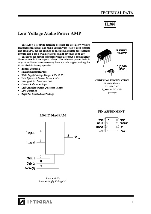
TECHNICAL DATA1Low Voltage Audio Power AMPThe IL386 is a power amplifier designed for use in low voltage consumer applications. The gain is internally set to 20 to keep external part count low, but the addition of an external resistor and capacitor between pins 1 and 8 will increase the gain to any value up to 200.The inputs are ground referenced while the output is automatically biased to one half the supply voltage. The quiescent power drain is only 24 milliwatts when operating from a 6 volt supply, making the IL386 ideal for battery operation.• Battery Operation• Minimum External Parts• Wide Supply Voltage Range: 4 V - 12 V • Low Quiescent Current Drain: 4 mA • Voltage Gains from 20 to 200• Ground Referenced Input• Self-Centering Output Quiescent Voltage • Low Distortion• Eight Pin Dual-In-Line PackageIL386PIN ASSIGNMENTLOGIC DIAGRAMPin 4 = GNDPin 6 = Supply Voltage V +IL3862MAXIMUM RATINGS *Symbol ParameterValue Unit V CC Supply Voltage 15V V IN Input Voltage ±0.4V P D Power Dissipation 1.25W Tstg Storage Temperature -65 to +150°C T J Junction Temperature +150°C T LLead Temperature+300°C*Maximum Ratings are those values beyond which damage to the device may occur.Functional operation should be restricted to the Recommended Operating Conditions.RECOMMENDED OPERATING CONDITIONSSymbol ParameterMin Max Unit V CC Supply Voltage4.012V T AOperating Temperature, All Package Types+70°CThis device contains protection circuitry to guard against damage due to high static voltages or electricfields. However, precautions must be taken to avoid applications of any voltage higher than maximum rated voltages to this high-impedance circuit. For proper operation, V IN and V OUT should be constrained to the range GND ≤(V IN or V OUT )≤V CC .Unused inputs must always be tied to an appropriate logic voltage level (e.g., either GND or V CC ).Unused outputs must be left open.ELECTRICAL CHARACTERISTICS (T A = 25°C)Symbol Parameter Test ConditionsGuaranteed Limits UnitMin TypMax V +Operating Supply Voltage412V I +Quiescent Current V + = 6 V, V IN = 08mA P O Output Power V += 6V, R L =8Ω, THD=10%V += 9V, R L =8Ω, THD=10%3251000mW A V Voltage Gain V += 6V, f=1kHz10µF from Pin 1 and 82646dB BW Bandwidth V += 6V, Pins 1 and 8 Open 250KHz THDTotal Harmonic DistortionV += 6V, R L =8Ω, P OUT =125mW,f=1kHz,Pins 1 and 8 Open1.0%PSRR Power Supply Rejection RatioV += 6V, f=1kHz, C BYPASS =10µF,Pins 1 and 8 Open45dB R IN Input Resistance 3080K ΩI BInput Bias CurrentV += 6V, Pins 2 and 3 Open 250nAIL341193APPLICATION INFORMATIONGAIN CONTROLTo make the IL386 a more versatile amplifier, two pins (1 and 8) are provided for gain control. With pins 1 and 8 open the 1.35 K Ω resistor sets the gain at 20 (26 dB). If a capacitor is put from pin 1 to 8,bypassing the 1.35 K Ω resistor, the gain will go up to 200 (46 dB). If a resistor is placed in series with the capacitor, the gain can be set to any value from 20 to 200. Gain control can also be done by capacitively coupling a resistor (or FET) from pin 1 to ground.Additional external components can be placed in parallel with the internal feedback resistors to tailor the gain and frequency response for individual applications. For example, we can compensate poor speaker bass response by frequency shaping the feeback path. This is done with a series RC from pin 1 to 5 (paralleling the internal 15 K Ω resistor). For 6 dB effective bass boots: R ≅15 K Ω, the lowest value for good stable operation is R=10 K Ω if pin 8is open. If pins 1 and 8 are bypassed then R as low as 2 K Ω can be used. This restriction is because the amplifier is only compensated for closed-loop gains greater the 9.INPUT BIASINGThe schematic shows that both inputs are biased to ground with a 50 K Ω resistor. The base current of the input transistors is about 250 nA, so the inputs are at at out 12.5 mV when left open. If the dc source resistance oriving the IL386 is higher than 250 K Ω it will contribute very little additional offset (about 2.5 mV at the input, 50 mV at the output). If the dc source resistance is less than 10 K Ω, then shorting the unused input to ground will keep the offset low (about 2.5 mV at the input, 50 mV at the output). For dc source resistances between these values we can eliminate excess offset by putting a resistor from the unesed input to ground, equal in value to the dc source resistance. Of course all affset problems are eliminated if the input is capacitively coupled.When using the IL386 with higher gains (by pessing the 1.35 K Ω resistor between pins 1 and 8) it is necessary to bypass the unused input, preventing degradation of gain and possible instabilities. This is done with a 0.1 µF capacitor or a short to ground depending on the dc source resistance on the driven input.SCHEMATIC DIAGRAM。
hiokl 3862-20 钳型表中文手册

操作手册3286-20 钳式功率计目录引言------------------------- 1 货运点检------------------------- 1 安全性------------------------- 2 使用注意事项------------------------- 3 该手册的结构------------------------- 5 第1章概述------------------------- 6 1.1产品概述------------------------- 6 1.2 特点------------------------- 6 1.3各部分名称和功能------------------------- 7 1.4 按键操作流程表-------------------------10 第2章测试步骤-------------------------13 2.1 准备-------------------------13 2.2 连接-------------------------13 2.3 量程设置-------------------------16 2.4 功率测量-------------------------17 2.5 谐波测量-------------------------22 2.6 数据保持功能-------------------------23 2.7 慢模式-------------------------23 2.8 记录功能-------------------------23 2.9 设置功能-------------------------24 2.10 测量条件储存功能-------------------------25 2.11 自动关机功能-------------------------25 2.12 电池电量低报警-------------------------26 2.13 蜂鸣声-------------------------26 第3章技术参数-------------------------27 3.1 测量参数-------------------------27 3.2 通用参数-------------------------31 3.3 运算公式-------------------------32 第4章更换电池-------------------------34 第5章安装手带-------------------------35 第6章收入携带盒-------------------------36 第7章故障解决-------------------------37引言感谢您购买HIOKI 3286-20 电力谐波分析仪,为了最大限度的发挥测试仪的功能,请首先仔细阅读该使用手册,并保留以备随时查阅。
lm386中文资料_数据手册_参数
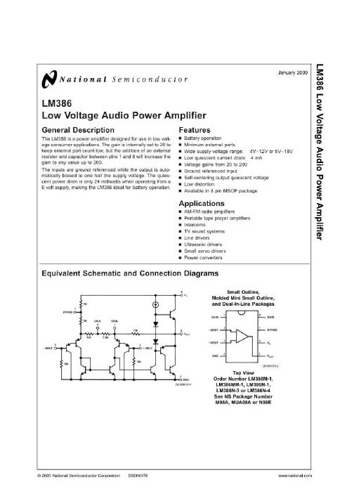
LM386低压音频功率放大器一般描述 LM386是一款功率放大器,设计用于低压,年龄消费者应用.增益内部设置为20至保持外部 零件数量低,但增加了外部引脚1和8之间的电阻和电容会增加获得高达200的任何值.输入以地为参考,输出为自动输入,基本 偏置到电源电压的一半.静止 - 从A.工作时仅消耗24毫瓦的功率 6伏电源,使LM386成为电池操作的理想选择.特征 ?电池操作 ?小 的外部零件 ?宽电源电压范围: 4V-12V或5V-18V ?低静态电流消耗: 4毫安 ?电压从20增加到200 ?接地参考输入 ?自对中输出静态 电压 ?低失真 ?采用8引脚MSOP封装应用 ? AM-FM无线电放大器 ?便携式磁带放大器 ?对讲机 ?电视音响系统 ?线驱动程序 ?超声波 驱动程序 ?小型伺服驱动器 ?电源转换器等效原理图和连接图 DS006976-1小轮廓,被铸造的微型小大纲,和双列直插式封装 DS006976-2顶视图订单号码LM386M-1, LM386MM-1,LM386N-1, LM386N-3或LM386N-4参见NS包装号码 M08A,MUA08A或 N08E 2000年1月 ?2000 NATIONAL SEMICONDUCTOR CORPORATION DS006976 (LM386N-1,-3,LM386M-1) 15V电源电压(LM386N-4) 22V封装耗散(注3) (LM386N) 1.25W (LM386M) 0.73W (LM386MM-1) 0.595W输入电压 ± 0.4V储存温度 -65?C至+150?C工作温度 0?C至+70?C结温 + 150焊接信息双列直插式封装焊接 (10秒) + 260C小外形包装 (SOIC和MSOP)气相(60秒) + 215C红外线(15秒) + 220C参见AN-450“表面安装方法及其作用 关于产品可靠性“的其他焊接方法表面贴装器件.热阻 θ JC (DIP) 37?C/ W θ JA (DIP) 107C / W θ JC (SO包) 35°C / W θ JA (SO包) 172C / W θ JA (MSOP) 210C / W θ JC (MSOP) 56C / W 电气特性 (注1,2) ? A =25?C参数条件敏典型马克 斯单位工作电源电压(V S ) LM386N-1,-3,LM386M-1,LM386MM-1 4 12 V LM386N-4 518 V静态电流(I Q )V S = 6V,V IN = 04 8嘛输出功率(P OUT ) LM386N-1,LM386M-1,LM386MM-1 V S = 6V,R L =8Ω,THD = 10% 250 325毫瓦 LM386N-3 V S = 9V,R L =8Ω,THD = 10% 500 700毫瓦 LM386N-4 V S = 16V,R L =32Ω,THD = 10% 700 1000毫瓦电压增益(A V )V S = 6V,f = 1kHz 26分贝从引脚1到8的10μF 46分贝带宽(BW) V S = 6V,引脚1和8打开 300千赫总谐波失真(THD) V S = 6V,R L =8Ω,P OUT = 125mW 0.2 % f = 1 kHz,引脚1和8打开电源抑制比(PSRR) V S = 6V,f = 1kHz,C BYPASS =10μF 50分贝引脚1 和8打开,参考输出输入电阻 应用提示增益控制为了使LM386成为更通用的放大器,两个引脚(1和8)用于增益控制.引脚1和8打开 1.35 k Ω电阻将增益设置 为20(26 dB).如果是电容从引脚1到8,绕过1.35 k Ω电阻,增益将达到200(46 dB).如果电阻串联放置与电容器,增益可以设 置为从20的任何值增益控制也可以通过电容式cou-将引脚1的电阻(或FET)接地.额外的外部组件可以并行放置通过内部反馈电 阻来调整增益和频率,针对个别应用程序的响应.例如,我们可以通过fre- quency形成反馈路径.这是一系列的 RC从引脚1到5(并 联内部15 k Ω电阻).对于6 dB有效低音提升:R ?15kΩ ,低值为了良好的稳定运行,R = 10k如果管脚8打开,则为Ω.如果针脚 1 和8旁路,然后R低至2 k可以使用Ω.这个限制是因为放大器只能被补偿闭环增益大于9.输入偏移原理图显示了两个输入都被偏置 到地 witha50k Ω电阻.输入变压器的基极电流,电阻约为250 nA,因此输入电压约为12.5 mV当打开时.如果直流源电阻驱动LM386 高于250 k它会贡献很少额外的偏移量(输入端约为2.5 mV,输出端为50 mV).如果直流源电阻小于10k Ω,然后短路未使用的 接地输入将保持偏移量低(约2.5 mV)在输入端,输出端为50 mV).直流源电阻从未使用的输入到地电阻,等于值到直流电源 电阻.当然,如果输入电容耦合,则会消除电源.当使用具有较高增益的LM386(绕过 1.35 k引脚1和8之间的Ω电阻)传递未使用 的输入,防止增益的降低可能的不稳定.这是用0.1μF电容或根据直流源电阻上的接地短路驱动输入
UTC386中文资料

DIP-8
BLOCK DIAGRAM
6 VCC
7 Bypass
15k 15k
8 Gain
1 Gain
15k
Gain 5 Output 3 +Input
1
8
Gain
-Input
2
7 Bypass
2 -Input
150
1.35k
UTC386
+Input
3
6
VCC
50k
50k
4 GND
GND
4
5
Output
Fig. 2 GV =200
Vs
6 1 8 250µF 5 7 4 bypass
0.05µF
10µF
Vin3UTC来自867 10k 4Vin
3
UTC386
10
YOUW ANG ELECTRONI CO. CS LTD
2
The UTC386 is a power amplifier designed for use in low voltage consumer applications. The gain is internally set to 20 keep the external part count low, but the additional of external resistor and capacitor between pin 1 and pin 8 will increase the gain to any value up to 200.
FEATURES
*Battery operation *Minimum external parts *Wide supply voltage range:4V~12V *Low quiescent current drain(4mA) *Voltage gains:20~200 *Ground referenced input *Self -centering output quiescent voltage *low distortion
LM386(音频功放)
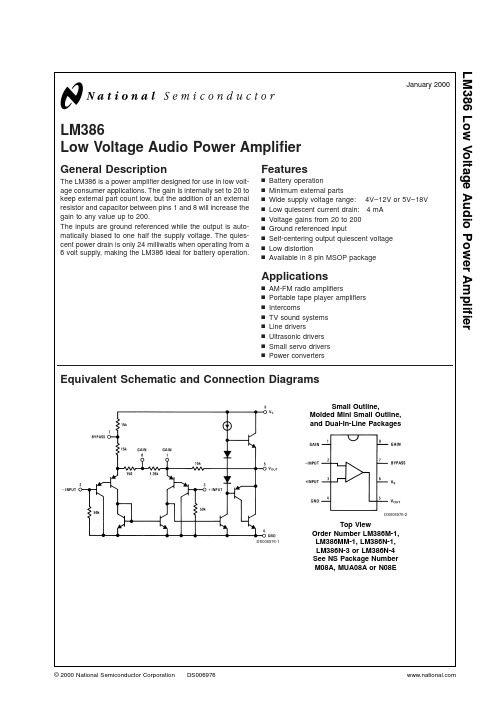
Dual-In-Line Package Soldering (10 sec) +260˚C Small Outline Package (SOIC and MSOP) Vapor Phase (60 sec) +215˚C Infrared (15 sec) +220˚C See AN-450 “Surface Mounting Methods and Their Effect on Product Reliability” for other methods of soldering surface mount devices. Thermal Resistance 37˚C/W θJC (DIP) 107˚C/W θJA (DIP) 35˚C/W θJC (SO Package) 172˚C/W θJA (SO Package) 210˚C/W θJA (MSOP) 56˚C/W θJC (MSOP)
Conditions
Min 4 5
Typ
Max 12 18
Units V V mA mW mW mW dB dB kHz % dB kΩ nA
VS = 6V, VIN = 0 VS = 6V, RL = 8Ω, THD = 10% VS = 9V, RL = 8Ω, THD = 10% VS = 16V, RL = 32Ω, THD = 10% VS = 6V, f = 1 kHz 10 µF from Pin 1 to 8 VS = 6V, Pins 1 and 8 Open VS = 6V, RL = 8Ω, POUT = 125 mW f = 1 kHz, Pins 1 and 8 Open VS = 6V, f = 1 kHz, CBYPASS = 10 µF Pins 1 and 8 Open, Referred to Output 250 500 700
LM386规格书

ORDERING INFORMATION
Normal LM386-S08-R LM386-S08-T LM386-P08-R LM386-P08-T LM386-D08-T
Ordering Number Lead Free
LM386L-S08-R LM386L-S08-T LM386L-P08-R LM386L-P08-T LM386L-D08-T
open the 1.35 kΩ resistor sets the gain at 20(26dB),If a capacitor is put from pin 1 to 8,bypassing the 1.35 kΩ resistor, the gain will go up to 200(46dB).If a resistor is placed in series with the capacitor, the gain can be set to any value from 20 to 200.Gain control can also be done by capacitively coupling a resistor (or FET) from pin 1 to ground. Additional external components can be placed in parallel with the internal feedback resistors to tailor the gain and frequency response for individual applications. For example we can compensate poor speaker bass response by frequency shaping the feedback path. This is done with a series RC from pin 1 to 5 (paralleling the internal 15 kΩ resistor). For 6 dB effective bass boost: R=15 kΩ, the lowest value for good stable operation is R=10 kΩ, if pin 8 is open, If pins 1 and 8 are bypassed then R as low as 2 kΩ can be used. This restriction is because the amplifier is only compensated for closed-loop gains greater than 9.
集成功率放大器电路的特点

图4-38 LM386外形与引脚功能
积件 4-4-1:认识集成功放电路
(3)LM386功放集成电路功能框图
图4-39 LM386功放集成电路功能框图 1)输入级由差分放大器组成,该电路可以减少直接耦合造成的直流工作点的不 稳定。 2)中间放大电路要求有高的电压放大倍数,所以由共射电路构成,它为输出级 提供足够大的信号电压。 3)输出级要驱动负载,所以要求其输出电阻小,输出电压幅度高,输出功率大, 因此采用准互补对称功率放大电路。
积件 4-4-1:认识集成功放电路
(4)LM386集成功放的典型应用
图4-40 LM386集成功放的典型电路图
LM386的5脚外接电容 器C3为功放输出电容, 以便构成OTL功率放大 电路,R1、C4是串联频 率补偿电路,用以抵消
扬声器的音圈电感在高
频时产生的不良影响,
并改善功率放大电路的
高频特性和防止高频自 激。输入信号ui绒 C1耦 合电容接入LM386集成 电路的输入端3脚,另一 个输入端2脚接地,故构 成单端输入方式。
2、集成功放的种类: (1)从用途划分:
1)通用型功放:适用于各种不同的场合,用途比较广泛。 2)专用型功放:适用于某种特定的场合。
(2)从芯片内部的构成划分: 1)单通道功放 2)双通道功放
(3)从功率划分: 1)小功率功放 2)大功率功放
积件 4-4-1:认识集成功放电路
3、LM386及构成的OTL功率放大电路 (1)M386简介: LM386是一种低电压通用集成功率放大器,采用双列直插式塑料封装。典
PSPiceLM386报告
PSPice:计算机仿真LM386实验报告学院:通信工程班级:1401052成员:黄莹14040520006何佩14170110016毕媛媛14010520048陈仕豪14010520049实验目的:计算机仿真由小组集体完成,可以自行组织团队协作方式,最后每组提交一份实验报告。
在技术层面要达到的要求:1、会使用PSPice对电路中的音频放大器进行仿真;2、会使用PSPice对电路中的电路元件设置参数;3、会使用PSPice检查仿真的信号输出。
实验原理实验任务任务1:用你画的单兵电台的电路原理图进行仿真。
注意:只仿真音频放大部分,检查组件的参数是否设置正确。
为给电路图提供合适的输入(一般由无线电接收器提供),VSIN输入正弦信号,将频率设置为1KHz,将波形偏移(VOFF)设置为0,将振幅(V AMPL)设置为0.05V。
信号通过VSIN接入放大器电路,为了观察输出端生成的信号,需在放大器的输出端设置一个电压探测点。
设置PSPice瞬态分析选项(Analysis-->Setup--> Transient)print step为200ns、设置最终时间为5ms、step ceiling上限为100ns。
然后对电路图进行仿真(按F11快捷键)。
仿真过程会花费一定时间,之后会出现波形。
首次仿真,点击Analysis>>Examine Output,会出现一个以你保存的电路图为名的新窗口,将仿真结果保存,你需要在实验报告中整理实验结果,测量信号的振幅,这是实验报告中的第一个任务。
提示:点击光标按钮(cursor),将鼠标放置在特定的点即可测量振幅。
左击鼠标产生第一个光标,右击鼠标产生第二个光标:右下角会出现一个小窗口,该窗口中显示两个光标的X-Y坐标值,dif表示两个光标之间的差值。
任务2:分析电路图接下来通过仿真结果分析电路图,你需要记录每次实验的信息和结果、每次实验的实验结果分析、以及可以得出什么样的结论。
迷你电子琴功能和原理介绍111031

迷你电子琴 一、功能说明音乐无时不刻伴随这我们的生活,一曲动听的音乐可以让我们紧张的情绪得以邂逅。
迷你电子琴,就是运用单片机和RC 震荡电路模拟了音乐中21个音阶的频率。
通过按键进行控制,发出不同的音调,弹出优美的音乐。
二、电路功能简介迷你电子琴由三个RC 桥式正弦波振荡电路、按键电路、LM386音频功放电路、数码管显示电路和单片机控制电路组成。
电子琴的高、中音由单片机内部定时器发出。
而低音部分我们采用了3个RC 桥式正弦波振荡电路模拟音阶的频率。
在通过LM386音频功放进行放大,扬声器输出。
另外,我们还采用了数码管显示当前音调的简谱,让我们的电子琴变得有声有色。
RC 桥式正弦波振荡电路原理如图所示,图中集成运放A 作为放大器,RC 串并联网络组成选频网络,同时也作为振荡器的正反馈网络,R1、Rf 组成电压负反馈以起到稳定和改善输出波形的作用。
起振条件: (略大于1)结果:产生增幅振荡稳幅过程:起振时, 稳定振荡时,稳幅措施:1、被动:器件非线性2、主动:在反馈网络中加入非线性稳幅环节,用以调节放大电路的增益1||>F A1||>F A 1..=F A三、芯片介绍1.STC10F08STC11/10××系列是宏晶科技设计生产的单时钟的单片机,指令代码完全兼容传统的8051,且速度快8-12倍。
是传统89C51系列的理想替代品。
STC10F08的引脚图STC11F08的特点:1、增强型8051CPU,1T,完全兼容8051指令2、工作电压:5.5-4.1V3、工作频率:0-35MHz4、用户Flash:8k,RAM:2565、通用I/O:40/36,LQFP-44封装增加了P4.0-P4.3口6、内部资源:UART串口、定时/计数器、内部低压中断、支持掉电唤醒、内置复位并可选择复位门槛电压、看门狗引脚如图所示。
2.集成电路LM324LM324是四运放集成电路,它采用14脚双列直插塑料封装,外形如图2所示。
NGA-386中文资料
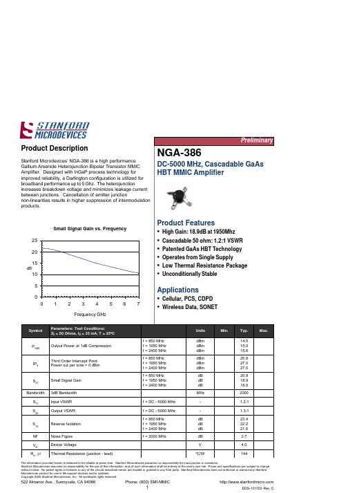
The information provided herein is believed to be reliable at press time. Stanford Microdevices assumes no responsibility for inaccuracies or omissions.Stanford Microdevices assumes no responsibility for the use of this information, and all such information shall be entirely at the user’s own risk. Prices and specifications are subject to change without notice. No patent rights or licenses to any of the circuits described herein are implied or granted to any third party. Stanford Microdevices does not authorize or warrant any StanfordThe information provided herein is believed to be reliable at press time. Stanford Microdevices assumes no responsibility for inaccuracies or omissions.Stanford Microdevices assumes no responsibility for the use of this information, and all such information shall be entirely at the user’s own risk. Prices and specifications are subject to change without notice. No patent rights or licenses to any of the circuits described herein are implied or granted to any third party. Stanford Microdevices does not authorize or warrant any StanfordNGA-386 DC-5.0 GHz 4.0V GaAs HBTAbsolute Maximum Ratingsre t e m a r a P e u l a V t i n U t n e r r u C y l p p u S 09A m e g a t l o V e c i v e D 0.6V e r u t a r e p m e T g n i t a r e p O 58+o t 04-C ºr e w o P t u p n I m u m i x a M 01+m B d e g n a R e r u t a r e p m e T e g a r o t S 051+o t 04-C ºer u t a r e p m e T n o i t c n u J g n i t a r e p O 051+CºOperation of this device above any one of these parameters may cause permanent damage.Bias Conditions should also satisfy the following expression: I D V D (max) < (T J - T OP )/R th ,j-lKey parameters, at typical operating frequencies:The information provided herein is believed to be reliable at press time. Stanford Microdevices assumes no responsibility for inaccuracies or omissions.Stanford Microdevices assumes no responsibility for the use of this information, and all such information shall be entirely at the user’s own risk. Prices and specifications are subject to change without notice. No patent rights or licenses to any of the circuits described herein are implied or granted to any third party. Stanford Microdevices does not authorize or warrant any StanfordNGA-386 DC-5.0 GHz 4.0V GaAs HBTApplication Schematic for Operation at 1950 MHzR bias1uF22pFThe information provided herein is believed to be reliable at press time. Stanford Microdevices assumes no responsibility for inaccuracies or omissions.Stanford Microdevices assumes no responsibility for the use of this information, and all such information shall be entirely at the user’s own risk. Prices and specifications are subject to change without notice. No patent rights or licenses to any of the circuits described herein are implied or granted to any third party. Stanford Microdevices does not authorize or warrant any StanfordNGA-386 DC-5.0 GHz 4.0V GaAs HBTdBdB dBdB S-parameters over frequency, at 25ºCFrequency GHz Frequency GHzFrequency GHz Frequency GHzThe information provided herein is believed to be reliable at press time. Stanford Microdevices assumes no responsibility for inaccuracies or omissions.Stanford Microdevices assumes no responsibility for the use of this information, and all such information shall be entirely at the user’s own risk. Prices and specifications are subject to change without notice. No patent rights or licenses to any of the circuits described herein are implied or granted to any third party. Stanford Microdevices does not authorize or warrant any StanfordNGA-386 DC-5.0 GHz 4.0V GaAs HBTTypical S-Parameters, I= 35mA ( No external matching, de-embedded to device leads)Stanford Microdevices assumes no responsibility for the use of this information, and all such information shall be entirely at the user’s own risk. Prices and specifications are subject to change without notice. No patent rights or licenses to any of the circuits described herein are implied or granted to any third party. Stanford Microdevices does not authorize or warrant any Stanford NGA-386 DC-5.0 GHz 4.0V GaAs HBTPart Number Ordering Informationr e b m u N t r a P ez i S l e e R le e R /s e c i v e D 683-A G N "70001Caution: ESD sensitiveAppropriate precautions in handling, packaging and testing devices must be observed.Package DimensionsThe part will be symbolized with a “N3” designator on the top surface of the package.Part SymbolizationNGA-386 DC-5.0 GHz 4.0V GaAs HBTComponent Tape and Reel PackagingTape DimensionsFor 86 OutlineThe information provided herein is believed to be reliable at press time. Stanford Microdevices assumes no responsibility for inaccuracies or omissions.Stanford Microdevices assumes no responsibility for the use of this information, and all such information shall be entirely at the user’s own risk. Prices and specifications are subject to change without notice. No patent rights or licenses to any of the circuits described herein are implied or granted to any third party. Stanford Microdevices does not authorize or warrant any Stanford。
- 1、下载文档前请自行甄别文档内容的完整性,平台不提供额外的编辑、内容补充、找答案等附加服务。
- 2、"仅部分预览"的文档,不可在线预览部分如存在完整性等问题,可反馈申请退款(可完整预览的文档不适用该条件!)。
- 3、如文档侵犯您的权益,请联系客服反馈,我们会尽快为您处理(人工客服工作时间:9:00-18:30)。
七夕,古今诗人惯咏星月与悲情。
吾生虽晚,世态炎凉却已看透矣。
情也成空,且作“挥手袖底风”罢。
是夜,窗外风雨如晦,吾独坐陋室,听一曲《尘缘》,合成诗韵一首,觉放诸古今,亦独有风韵也。
乃书于纸上。
毕而卧。
凄然入梦。
乙酉年七月初七。
-----啸之记。
LM386说明:
一、概述(Des cription):
LM386是美国国家半导体公司生产的音频功率放大器,主要应用于低电压消费类产品。
为使外围元件最少,电压增益内置为20。
但在1脚和8脚之间增加一只外接电阻和电容,便可将电压增益调为任意值,直至200。
输入端以地位参考,同时输出端被自动偏置到电源电压的一半,在6V电源电压下,它的静态功耗仅为24mW,使得LM386特别适用于电池供电的场合。
LM386的封装形式有塑封8引线双列直插式和贴片式。
二、特性(Features):
静态功耗低,约为4mA,可用于电池供电。
工作电压范围宽,4-12V or 5-18V。
外围元件少。
电压增益可调,20-200。
低失真度。
典型应用电路。
