Hyperfine Spectroscopy of Optically Trapped Atoms
视网膜母细胞瘤组织中赖氨酸羟化酶2表达及其对瘤细胞迁移和侵袭的影响

视网膜母细胞瘤组织中赖氨酸羟化酶2表达及其对瘤细胞迁移和侵袭的影响章晋伟;曹刚琴;汪建【期刊名称】《现代检验医学杂志》【年(卷),期】2022(37)3【摘要】目的探讨前胶原赖氨酸-2-酮戊二酸-5-双加氧酶2(procollagen-lysine2-oxoglutarate 5-dioxygenase 2,PLOD2)在视网膜母细胞瘤中的表达,以及下调该基因对细胞迁移和侵袭的影响。
方法选取2011年3月~2019年3月在湖北省大冶爱尔眼科医院和中国人民解放军广州军区武汉总医院行眼球摘除手术治疗的视网膜母细胞瘤患儿73例,同期,留取正常视网膜组织32例作为对照组,免疫组织化学法检测视网膜母细胞瘤和对照组组织中PLOD2蛋白表达,培养Y79细胞并分为PLOD2干扰组(I组)、阴性对照组(NC组)和空白组(B组),分别转染PLOD2干扰序列、阴性对照序列及不作任何处理,RT-qPCR检测PLOD2 mRNA表达,Transwell 法检测细胞迁移和侵袭能力,Western blot法检测PLOD2,E-钙黏蛋白(E-cadherin,E-cad)和N-钙黏蛋白(N-cadherin,N-cad)表达。
结果与对照组相比,在视网膜母细胞瘤组织中PLOD2蛋白阳性表达率升高(75.34%vs 25.00%),差异有统计学意义(χ^(2)=23.493,P<0.001);与国际眼内视网膜母细胞瘤分类(intraocular international retinoblastoma classife,IIRC)D期[18(60%)]、未发生脉络膜浸润[31(65.96%)]和未发生视神经浸润[22(62.86%)]比较,IIRC分期E期[37(86.05%)]、发生脉络膜浸润[24(92.31%)]和发生视神经浸润[33(86.84%)]的视网膜母细胞瘤患者组织中PLOD2蛋白阳性表达率明显升高,差异均有统计学意义(χ^(2)=6.453,6.256,5.642,均P<0.05);与NC组和B组比较,在I组细胞中PLOD2mRNA相对表达量明显降低(0.27±0.09 vs 1.01±0.08,1.00±0.05),差异有统计学意义(F=183.919,P<0.001);与NC组和B组比较,下调PLOD2表达后细胞迁移能力和侵袭能力均显著降低(F=10.163,24.094,均P<0.05);与NC组和B组比较,下调PLOD2表达后N-cad蛋白相对表达量明显降低,而E-cad蛋白相对表达量明显升高,差异均有统计学意义(F=62.122,36.641,均P<0.001)。
相干光断层扫描对532 nm激光治疗糖尿病黄斑水肿的疗效观察
相干光断层扫描对532 nm激光治疗糖尿病黄斑水肿的疗效观察潘颖喆;高丰;王慧;殷晖【期刊名称】《临床眼科杂志》【年(卷),期】2011(19)4【摘要】Objective To observe the clinical effect of 532nm laser photocoagulation therapy on diabetic macular edema with optical coherence tomography. Methods 46 continuous patients ( 61 eyes ) with clinically significant diabetic macula edema were treated by 532nm laser photocoagulation. The retinal thickness and the volume of central fovea of macula were detected by optical coherence tomography in pre-photocoagulation and post-photocoagulation after 3 months. These data and the visual acuity were analyzed statistically. Results The visual acuity in 41 eyes improved and 17 eyes unchanged after 532 nm photocoagulation. The retinal thickness and the volume of central fovea of macula in pre-photocoagulation and post-photocoagulation after 3 months were 354.7 ± 93.2 μm/8.32 ± 0.53 mm3 and 203.5 ± 49.6 μm/7.24 ±0.41 mm3 respectively. Statistically, the difference in pre-photocoagulation and post-photocoagulation was significant. Conclusion 532nm laser photocoagulation is an effective treatment for diabetic macular edema. The change of retinal thickness and the volume can be measured exactly with optical coherence tomography pre- and post-photocoagulation, and thus the accurate effect of 532nm laser photocoagulation can be evaluated exactly.%目的评价使用相干光断层扫描(OCT)对532 nm激光治疗糖尿病黄斑水肿的疗效进行观察的有效性.方法对糖尿病性有临床意义的黄斑部水肿病例46例(61只眼),给予532 nm激光黄斑格栅样光凝、局灶光凝以及全视网膜光凝,在治疗前、治疗后3个月分别进行裸眼视力、眼底照相、荧光素眼底血管造影及OCT黄斑区视网膜厚度及视网膜容积等检查.比较光凝前后黄斑区视网膜厚度和视网膜容积的变化.结果在46例(61只眼)中,41只眼视力提高,17只眼不变,所有患者荧光素眼底血管造影显示黄斑区荧光渗漏不同程度减轻或消失,OCT显示光凝治疗前黄斑中心凹视网膜神经上皮厚度为(354.7±93.2) μm,光凝3个月后为(203.5±49.6) μm(P<0.05),光凝治疗前黄斑区6 mm直径神经上皮总体容积为(8.32±0.53) mm3,光凝3个月后为(7.24±0 41) mm3(P<0.05).结论 OCT可以对糖尿病性黄斑水肿进行定量的诊断,并且可以对激光光凝治疗后黄斑水肿的消退进行准确的测量和评价.【总页数】3页(P305-307)【作者】潘颖喆;高丰;王慧;殷晖【作者单位】441000,湖北省襄阳市第一人民医院眼科;441000,湖北省襄阳市第一人民医院眼科;441000,湖北省襄阳市第一人民医院眼科;441000,湖北省襄阳市第一人民医院眼科【正文语种】中文【相关文献】1.调Q532nm激光联合2940nm点阵铒激光治疗斑痣64例疗效观察 [J], 李潼;杨力;殷悦2.光相干断层扫描在氪激光治疗糖尿病黄斑水肿疗效观察的应用研究 [J], 张亚丽;杜磊;朱霞;王娟;赵雪;刘佩3.倍频532nm激光光凝治疗糖尿病黄斑水肿疗效观察 [J], 崔钢峰;牟月红;林咸平4.577 nm黄色阈下微脉冲激光治疗糖尿病黄斑水肿的疗效观察 [J], 邹博5.Q开关532nm激光联合超脉冲CO2激光治疗脂溢性角化病疗效观察 [J], 董郁红;赵小玲因版权原因,仅展示原文概要,查看原文内容请购买。
基于间接波前整形的近红外二区荧光共聚焦成像研究

文章编号 2097-1842(2024)01-0150-10基于间接波前整形的近红外二区荧光共聚焦成像研究谭 天1,2,史天悦2,吴长锋2,彭洪尚1 *(1. 中央民族大学 理学院 光子系统工程软件教育部工程研究中心, 北京 100081;2. 南方科技大学 生物医学工程系, 广东 深圳 518055)摘要:生物组织散射引起的光学像差限制了光学系统的成像性能。
本文研究了基于间接波前整形的近红外二区荧光共聚焦成像技术。
首先,制备了高效率近红外二区荧光探针,降低该波段生物组织的散射有助于实现高对比度的活体组织成像。
其次,研究了基于间接波前测量的自适应光学方法,将间接波前整形技术应用于激光扫描共聚焦显微系统中,以实现对生物组织引起的光学像差的测量与补偿,获得生物组织的高信噪比成像。
最后,对基于间接波前整形的近红外二区荧光共聚焦成像系统开展了相关实验。
实验结果表明,本系统对空气平板、散射介质和小鼠颅骨等产生的像差具有良好的补偿效果,最终信号强度较初始值分别提升了1.47、1.95和2.85倍,显著提升了最终的成像质量。
关 键 词:间接波前整形;近红外二区成像;共聚焦成像;活体实验中图分类号:O439 文献标志码:A doi :10.37188/CO.2023-0070NIR-II fluorescence confocal imaging based onindirect wavefront shapingTAN Tian 1,2,SHI Tian-yue 2,WU Chang-feng 2,PENG Hong-shang 1 *(1. Engineering Research Center of Photonic Design Software Ministry of Education , College of Science ,Minzu University of China , Beijing 100081, China ;2. Department of Biomedical Engineering , Southern University of Science and Technology ,Shenzhen 518055, China )* Corresponding author ,E-mail : ****************.cnAbstract : Optical aberrations caused by the scattering of biological tissues limit the imaging performance of optical systems. A near-infrared II fluorescence confocal imaging technique based on indirect wavefront shaping was investigated. First, we synthesized a highly efficient near-infrared II range fluorescent probe,收稿日期:2023-04-18;修订日期:2023-05-10基金项目:国家自然科学基金(No. 62175266, No. 62235007, No. 22204070);深圳市科技计划项目(No. KQTD20170810111314625, No. JCYJ20210324115807021, No. SGDX20211123114002003);深圳湾实验室开放课题(No.SZBL2021080601002);广东省先进生物材料重点实验室(No. 2022B1212010003)Supported by the National Natural Science Foundation of China (No. 62175266, No. 62235007, No.22204070); the Shenzhen Science and Technology Program (No. KQTD20170810111314625, No. JCYJ20210324115807021, No. SGDX20211123114002003); the Shenzhen Bay Laboratory (No. SZBL2021080601002);Guangdong Provincial Key Laboratory of Advanced Biomaterials (No. 2022B1212010003)第 17 卷 第 1 期中国光学(中英文)Vol. 17 No. 12024年1月Chinese OpticsJan. 2024where reducing the scattering of biological tissue can realize biopsy imaging with high-contrast. Second, we investigated the adaptive optical method based on indirect wavefront measurement. The indirect wavefront shaping technology was applied to the laser scanning confocal system, enabling the measurement and com-pensation of optical aberrations caused by biological tissues, and obtaining imaging of biological tissues with a high signal-to-noise ratio. Finally, near-infrared II fluorescence confocal imaging system based on indirect wavefront shaping was deployed and relevant experiments were conducted. The experimental results indic-ate that the system effectively compensates for the aberrations induced by air plates, scattering media and mouse skull, and increases the final signal intensity by 1.47, 1.95 and 2.85 times, respectively. As a result, the final imaging quality is significantly enhanced.Key words: Indirect wavefront shaping;near-infrared-II imaging;confocal imaging;in vivo experiments1 引 言高分辨率的光学成像技术一直是推动生物学发展的主要手段,在生物分子解构[1]、光遗传[2]和细胞形态学[3]等方面发挥着不可替代的作用。
高效稳定的Cr3+离子激活石榴石型宽带近红外荧光粉的发光特性及应用研究(英文)
441第 3 期王靖涛,等:无压烧结制备Y2MgAl4SiO12∶Ce3+荧光陶瓷及光学性能Eng., 2012, 6(1): 13-26.[2]ARJOCA S, VÍLLORA E G, INOMATA D,et al. Temperature dependence of Ce∶YAG single-crystal phosphors for high-brightness white LEDs/LDs [J].Mater. Res. Express, 2015, 2(5): 055503.[3]WIERER J J JR, TSAO J Y, SIZOV D S. Comparison between blue lasers and light-emitting diodes for future solid-state lighting [J].Laser Photon. Rev., 2013, 7(6): 963-993.[4]LI J, SAHI S, GROZA M,et al. Optical and scintillation properties of Ce3+‐doped LuAG and YAG transparent ceramics:a comparative study [J].J. Am. Ceram. Soc., 2017, 100(1): 150-156.[5]STERANKA F M, BHAT J, COLLINS D,et al. High power LEDs-technology status and market applications [J].Phys.Status Solidi A, 2002, 194(2): 380-388.[6]ZHOU T, LIU X L, LIU Q S,et al. Highly thermal stable and color tunable composite fluorescent ceramics for high-pow‐er white LEDs [J].Ceram. Int., 2022, 48(13): 18716-18722.[7]JIA L C, ZHU J J, BOYARYNTSEVA Y,et al. Effect of carbon doping on F‐type defects in YAG and YAG∶Ce crystals [J].Phys. Status Solidi B, 2021, 258(12): 2100325.[8]YANG L, ZHANG Q, LI F,et al. Thermally stable lead-free phosphor in glass enhancement performance of light emit‐ting diodes application [J].Appl. Opt., 2019, 58(15): 4099-4104.[9]ARMETTA F, SIBEKO M A, LUYT A S,et al. Influence of the Ce∶YAG amount on structure and optical properties of Ce∶YAG-PMMA composites for white LED [J].Z. Phys. Chem., 2016, 230(9): 1219-1231.[ 10 ]OSIPOV V V,ISHCHENKO A V,SHITOV V A,et al.Fabrication,optical and scintillation properties of transparent YAG∶Ce ceramics [J].Opt. Mater., 2017, 71: 98-102.[ 11 ]NISHIURA S, TANABE S, FUJIOKA K,et al. Properties of transparent Ce∶YAG ceramic phosphors for white LED [J].Opt. Mater., 2011, 33(5): 688-691.[ 12 ]杜傲宸,杜琪源,刘欣,等.高光效、大功率LEDs/LDs用Ce∶YAG透明陶瓷[J].无机材料学报, 2021, 36(8):883-892.DU A C, DU Q Y, LIU X,et al. Ce∶YAG transparent ceramics enabling high luminous efficacy for high-power LEDs/ LDs [J].J. Inorg. Mater., 2021, 36(8): 883-892.(in English)[ 13 ]LIANG M Z, XU J F, QIANG Y C,et al. Ce3+ doped BaLu2Al2Ga2SiO12:a novel blue-light excitable cyan-emitting phos‐phor with ultra-high quantum efficiency and excellent stability for full-spectrum white LEDs [J].J. Rare Earths, 2021,39(9): 1031-1039.[ 14 ]YAO Q, HU P, SUN P,et al. YAG∶Ce3+ transparent ceramic phosphors brighten the next-generation laser-driven lighting [J].Adv. Mater., 2020, 32(19): 1907888.[ 15 ]FENG S W,GUO Y C,ALLIX M,et al.Biphasic Lu3MgAl3SiO12-based transparent ceramics for uniform laser-diode-driven white lighting [J].Cell Rep. Phys. Sci., 2022, 3(9): 101044.[ 16 ]DU Q P, FENG S W, QIN H M,et al. Massive red-shifting of Ce3+ emission by Mg2+ and Si4+ doping of YAG∶Ce transpar‐ent ceramic phosphors [J].J. Mater. Chem.C, 2018, 6(45): 12200-12205.[ 17 ]PAN Z F,LI W Q,XU Y,et al.Structure and redshift of Ce3+emission in anisotropically expanded garnet phosphor MgY2Al4SiO12∶Ce3+[J].RSC Adv., 2016, 6(25): 20458-20466.[ 18 ]MENG Q H, WANG X J, ZHU Q,et al. The effects of Mg2+/Si4+ co-substitution for Al3+ on sintering and photolumines‐cence of (Gd, lu)3Al5O12∶Ce garnet ceramics [J].J. Eur. Ceram. Soc., 2020, 40(8): 3262-3269.[ 19 ]李江,李万圆,刘欣,等.固态照明/显示用荧光陶瓷研究进展[J].发光学报, 2021, 42(5): 580-604.LI J,L W Y,LIU X,et al.Research progress on phosphor ceramics for solid-state lighting/display [J].Chin.J.Lu⁃min., 2021, 42(5): 580-604.(in Chinese)[ 20 ]BABIN V,BLAZEK K,KRASNIKOV A,et al.Luminescence of undoped LuAG and YAG crystals [J].Phys.Status Solidi C, 2005, 2(1): 97-100.[ 21 ]ARJOCA S, VÍLLORAE G, INOMATA D,et al. High homogeneity, thermal stability and external quantum efficiency of Ce∶YAG single-crystal powder phosphors for white LEDs [J].J. Ceram. Soc. Japan, 2016, 124(5): 574-578.[ 22 ]SETLUR A A, HEWARD W J, GAO Y,et al. Crystal chemistry and luminescence of Ce3+-doped Lu2CaMg2(Si, Ge)3O12第 45 卷发光学报and its use in LED based lighting [J ]. Chem. Mater., 2006, 18(14): 3314-3322.[ 23 ]ARJOCA S , VÍLLORA E G , INOMATA D , et al . Ce ∶(Y 1-x Lu x )3Al 5O 12 single -crystal phosphor plates for high -brightnesswhite LEDs/LDs with high -color rendering (Ra >90) and temperature stability [J ]. Mater. Res. Express , 2014, 1(2):025041.王靖涛(1997-),男,四川成都人,硕士研究生,2020年于黑龙江科技大学获得学士学位,主要从事荧光陶瓷的研究。
核磁共振波谱课程教学探索

山东化工SHANDONGCHEMICALINDUSTRY-158-2020年第49卷核磁共振波谱课程教学探索李晓虹(苏州大学材料与化学化工学部,江苏苏州215123)摘要:核磁共振波谱作为鉴定化合物结构、组分含量、动力学参数等信息的重要手段,在化学、医药、材料等领域科研生产中起着关键作用。
其课程教学长期以来受到理论内容难、仪器开放难等因素困扰’结合苏州大学核磁共振波谱课程的双语教学实践提出了相应的对策与改进举措,探讨通过更新改进教学方法和内容,突破传统教学模式,使学生从理论联系实践,从“会用”到“用好”核磁技术’关键词:核磁共振波谱;远程虚拟终端%网络课堂中图分类号:G642O文献标识码:B文章编号:1008-021X(2020)23-0158-02Exploration of Teaching in Nuclear Magnetic Resonance Spectroscopy CourseLi Xiaohong(Colleae of Chemist—,Chemicai Enginee/ng and Materials Science of Soochow University,Suzhou215123,China) Abstract:Nuclear magnetic resonance spectroscopy(NMR),as an Onportant method of studying compound structures, component contents and kinetic parameters,plays a key rolo in the fields of chemist—,pharmaceutical indust—and materials science.For a long time,its course teaching has been troubled by the dOficulta of theo—tical content and the lack of instmmentai peacicce.Based on ihebcocnguaoieachcngpeacicceooNMR couesecn Soochow Unceeesciy,ihcspapeedcscu s eshow iobeeak iheough iheieadciconaoieachcngmodebycmpeoecngiheieachcngmeihodsand conienis,soihaisiudeniscan combcneiheoeywcih peacicceand makegood useooNMRiechnooogy.Key wordt:NMR%VNC%online coa s es核磁共振波谱作为鉴定化合物结构的重要手段,对样品无损,分辨率高,较灵敏,可获得准确的定性定量信息。
分子荧光光谱法

光致发光(Photoluminescence): 荧光和
磷光是分子吸光成为激发态分子,在返回基态时 的发光现象. 荧光:受光激发的分子从第一激发单重态的最低 振动能级回到基态所发出的辐射。 磷光: 从第一激发三重态的最低振动能级回到基 态所发出的辐射。
荧光分析法的特点
因 为 有 的 分 子 不 发 荧 光 。
1. 激发
在室温下物质分子大部分处于基态的最低振动能级且电子自旋配对为单重 态.当吸收一定频率的电磁辐射发生能级跃迁时,可上升到不同激发态 的各振动能级,其中多数分子上升至第一激发单重态这一过程约需1015秒. 激发
2 去活化过程
激发态分子的失活: 激发态分子不稳定,它要以辐射 或无辐射跃迁的方式回到基态
。荧光分光光度计既可用于定
量分析,也可用于测绘激发光谱 和荧光光谱。第一单色器选择激 发光波长(>250nm的 紫外光)故称为激发单色器
第二单色器(荧光单色器)
与激发光入射方向垂直, 并选择荧光波长,可提高方法的选择性和准确度。
荧光分析法的应用
无机物分析 无机离子中除少数例外一般不发荧光.但很多 无机离子能怀一些有机试剂形成荧光络合物,而进行定量 测定. 生物化学及生理医学方面的应用 荧光法对于生物中许多 重要的化合物具有很多的灵敏度和较好的物效性,故广用 于生物化学分析,生理医学和临床分析. 药物分析 目前还采用荧光分光光度计作为高效液相色谱,薄层色谱 和高效毛细管电泳等的检测器,使有效的分离手段与高灵 敏度,高选择性的测定方法结合起来,可用于测定复杂的混 合物.
荧光团杂化纳米二氧化硅微球
e-2.303εbc=1-2.303 εbc-(-2.303 εbc)2/2!-(-2.303 εbc)3/3!
对于很稀的溶液,投射到样品溶液上的被吸收的激发光不到2%时, 即εbc<=0.05时,上式的第二项后的各项可以忽略不计。则
光谱技术在潜艇舱室大气监测领域的适用性分析
Vol. 43, No. 1Jan., 2021第43卷第1期2021年1月舰船科学技术SHIP SCIENCE AND TECHNOLOGY光谱技术在潜艇舱室大气监测领域的适用性分析袁正洋1,赵俊涛1,施红旗1,王世忠1,周家勇1,余 涛"(1.武汉第二船舶设计研究所,湖北武汉430205; 2.北京航空航天大学,北京100091)摘 要:舱室大气环境是制约潜艇自持力的重要因素之一,大气监测的目的是保障人员生命安全,指导通风、净化系统运行,以及在大气组分浓度存在异常时及时警示。
光谱分析技术是当前环境组分监测领域常用的灵 敏、快速、准确的分析方法之一。
针对现阶段潜艇大气监测需求,本文重点介绍傅里叶变换红外光谱技术、可调谐 半导体激光吸收光谱技术、差分吸收光谱技术和光声光谱技术4种基于光学原理的空气组分监测技术的基本原理和应用现状,并对其应用于潜艇的适用性进行分析。
关键词:光谱技术;潜艇;大气监测;舱室空气质量中图分类号:U664.86 文献标识码:A文章编号:1672 - 7649(2021)01 - 0180 - 05 doi : 10.3404/j.issn,1672 - 7649.2021.01.034Applicability analysis of spectral technology in submarine cabin atmospheric monitoringYUAN Zheng-yang 1, ZHAO Jun-tao 1, SHI Hong-qi 1, WANG Shi-zhong 1, ZHOU Jia-yong 1, YU Tao 1'2(1. Wuhan Second Ship Design and Research Institute, Wuhan 430205, China; 2. Beihang University, Beijing 100091, China)Abstract: The atmospheric environment in the cabin is one of the important factors which restricts the self-sustainingforce of the submarine. The purpose of atmospheric monitoring are guaranteeing the safety of personnel, guiding the opera tion of ventilation & purification system, and timely warning when the concentration of atmospheric components is abnor mal. Spectral analysis is one of the sensitive, fast and accurate analysis methods which is commonly used in the field of en vironmental component monitoring. In order to achieve the requirements of submarine atmospheric monitoring in this period, this paper mainly introduces the basic principles and applications of four kinds of atmospheric monitoring technology basedon optical principle of Fourier transform infrared spectroscopy(FTIR), tunable diode laser absorption spectroscopy(TDLAS),differential optical absorption spectroscopy(DOAS) and photoacoustic spectroscopy(PAS). In addition, the applicability forsubmarine is analyzed.Key words: spectral technology ; submarine ; air monitoring ; cabin air qualityo 引言潜艇舱室环境是极为特殊的大型载人人工密闭环境,其内部设备与人员众多,且独立于外界大气系 统。
肺部肿瘤诊断高光谱显微成像结果初版公示

肺部肿瘤诊断高光谱显微成像结果初版公示近年来,肺癌的发病率不断上升,成为全球范围内的一大健康问题。
为了更准确地诊断和治疗肺部肿瘤,医学领域不断研发新的技术和方法。
在这个领域中,高光谱显微成像技术引起了广泛的关注。
本文旨在初版公示肺部肿瘤诊断的高光谱显微成像结果。
高光谱显微成像(Hyperspectral microscopy)是一种结合了光学显微镜和光谱分析的成像技术。
通过使用各种波长的光源对样本进行照射,并记录不同波长下的反射光谱信息,从而获得样本的高光谱图像。
这种技术可以提供更多细胞组织的光谱信息,帮助医生更好地识别和区分不同类型的细胞。
在肺癌的诊断中,高光谱显微成像技术可以提供多种重要信息。
首先,高光谱显微镜可以观察到细胞和组织的细微结构。
通过比较健康组织和肿瘤组织的细胞形态和结构,医生可以初步判断是否存在肺癌细胞。
其次,高光谱显微成像技术可以提供不同组织中血红蛋白的分布情况。
肺癌组织中的血供通常会受到异常的改变,这些改变可以在高光谱图像中以特定的光谱特征体现出来。
通过分析这些特征,医生可以了解肿瘤的血供情况,进而判断肿瘤的恶性程度和预测其生长速度。
除了上述的诊断信息,高光谱显微成像技术还可以提供肿瘤标志物的定量信息。
标志物是一种指示疾病存在和发展的生物标记,其浓度的变化可以反映疾病的进展情况。
通过在高光谱图像上分析并定量肿瘤标志物的含量,医生可以更准确地判断肺癌患者的病情,并据此制定更有效的治疗方案。
尽管高光谱显微成像技术在肺癌诊断领域有很大的潜力,但仍存在一些挑战和局限性。
首先,高光谱显微成像技术需要高精度的仪器设备和专业的操作技术,这增加了使用该技术的门槛。
其次,高光谱显微成像技术在临床应用中的标准化和规范化仍面临困难。
不同设备和操作者之间的差异可能导致结果的不一致性。
此外,对于一些肺癌的早期病变,高光谱显微成像技术的诊断准确性仍待提高。
为了进一步推广高光谱显微成像技术在肺癌诊断中的应用,我们建议采取以下措施。
绿色荧光蛋白(GFP) 的特性及其在分子生物学研究中 的应用

绿色荧光蛋白(GFP) 的特性及 其在分子生物学研究中 的应用
2.3 GFP融合蛋白用于研究蛋白质定位、移动 及相互作用
异质蛋白可以和GFP的N-端或C-端连接组成融合蛋白。GFP融合蛋白既保留了 异质蛋白的固有特性,也保留了GFP的正常活性。因此,GFP融合蛋白,实际上可 作为一种“荧光标签”用来研究蛋白质在细胞中的定位、转移、相互作用等内 容。Clontech公司构建了6种GFP融合蛋白载体。KaimSR利用GFP融合蛋白载 体研究细菌致病性,即用GFP融合蛋白载体转化沙门氏杆菌 (Salmonellatyphimurium),再侵染人的HEP-2细胞,并用若丹明(rhodaminephalloidin)染色,在荧光显微镜下观察。若细菌只侵染到细胞表面,只在细胞表面 呈现绿色荧光(GFP表达信号);若细菌已侵入细胞内部,则培养细胞呈现黄色荧光, 这是GFP表达的绿色荧55薛启汉:绿色荧光蛋白(GFP)的特性及其在分子生物学 研究中的应用光与细胞若丹明染色的红色荧光的重叠效果。因此,利用GFP融合 蛋白为“荧光标签”,可以直接活体观察到细菌蛋白和报告蛋白在细胞中的确切 位置,以表明细菌在活体细胞中的侵染状况。同样原理,Youvan构建了菸草花叶 病毒和GFP的融合蛋白载体TWV-GFP。Banlcombe DC构建了马铃薯X病毒和 GFP的融合蛋白载体PVX-GFP[41]接种菸草(N.clevelandii)1~2天后,在紫外光 下可以直接观察到病毒侵染的确切部位。再用首次感染的菸草汁液接种另一种 菸草(N.benthamiana),观察到已放大的第二次系统感染的绿色荧光斑点。叶片 提取液蛋白电泳凝胶在紫外光下也能见到GFP荧光信号,从感染叶片中回收的病 毒经鉴定,确认为PVX-GFP。构建载体时,直接用GFP基因替代病毒外壳蛋白基 因,接种后观察到GFP绿色荧光只局限于接种的细胞部位,不扩散。证实了早先 的论断,即PVX外壳蛋白对于病毒在寄主细胞内的增殖,以及在细胞间的移动、 扩展是不可缺少的条件[42,43,44,45,46,47]。显然,GFP融合蛋白作为一种报告 标记,可以为病毒学研究,或以病毒载体为途径研究外源基因在转基因生物细胞 中的表达及蛋白质定位,提供理想的工具[48,49,50]。与传统的荧光抗体相 比,GFP不仅灵敏度高,不需要反应底物,还可以消除因抗体与非靶位点结合带来 的背景荧光的干扰。
基于偏振光谱成像技术的上皮组织癌变早期诊断系统方案

科技型中小企业技术创新项目可行性研究报告推荐单位:项目名称:基于偏振光谱成像技术的上皮组织癌变早期诊断系统承担单位:中科麦特电子技术设备(盖章)二〇一二年二月第一部分项目概述偏振散射光谱技术,是一种无损在体光学检测技术,它利用后向偏振散射光来探测细胞核形态学参数的变化。
我们知道肿瘤的形成往往最先反映于上皮组织血氧含量异常和细胞核形态学参数的变化,如细胞核变大、形状和大小分布不规则、过染色等。
近红外后向散射光的偏振特征和光谱特征能够准确体现上皮组织的血氧含量、细胞核大小等信息,通过对上皮组织的后向散射光进行偏振光谱成像,对所获取的信息进行定量分析,就可以实现对病变组织的无损检测。
因此,测量上皮组织细胞后向散射光谱有望检测到早期癌症信号,从而实现早期治疗。
本项目从研究上皮组织偏振光谱成像机理出发,并结合组织的偏振光谱后向散射模型以及病变组织早期精确检测的特点,提出并研究基于偏振光谱成像的病变组织早期检测方法体系,建立组织偏振光谱成像传感器以及相应的偏振光谱图像超分辨方法,进而解决上皮组织病变区域的早期精确定位问题。
基于偏振光谱成像技术的上皮组织癌变早期诊断系统的创新在于:1、通过对多波段偏振感知特性和视觉神经偏振信息的处理方法,建立起了仿生视网膜多波段偏振处理的定量模型,为散射介质中目标检测和定位奠定基础。
开拓了研究散射介质中目标清晰图像的获取方法。
2、搭建了一个成像偏振探测系统,利用该系统采集了大量的偏振图像,对不同条件下获取的多种目标偏振图像进行对比分析,表明利用偏振信息能够提高上皮组织癌变早期的诊断的检测性能。
加深了基于光谱和偏振信息的散射介质中目标的定位的理论研究和实际的应用经验。
3、偏振参数图像在表达信息方面具有互补性和冗余性,根据I参数、偏振度和偏振角所包含信息的特征,提出了基于小波变换的偏振图像融合算法,有效的提高了图像的对比度和清晰度。
根据I参数、偏振度和偏振角图像共有信息和特有信息、之间的差异,提出了基于伪彩色的偏振图像融合算法,提高了人眼的分辨力,该算法可以增加图像的信息量。
p区金属氧化物Ga_(2)O_(3)和Sb_(2)O_(3)光催化降解盐酸四环素性能差异
收稿日期:2020⁃09⁃29。
收修改稿日期:2020⁃12⁃28。
国家自然科学基金(No.21875037,51502036)和国家重点研发计划(No.2016YFB0302303,2019YFC1908203)资助。
*通信联系人。
E⁃mail :***************.cn ,***************第37卷第3期2021年3月Vol.37No.3509⁃515无机化学学报CHINESE JOURNAL OF INORGANIC CHEMISTRYp 区金属氧化物Ga 2O 3和Sb 2O 3光催化降解盐酸四环素性能差异毛婧芸1黄毅玮2黄祝泉1刘欣萍1薛珲*,1肖荔人*,3(1福建师范大学环境科学与工程学院,福州350007)(2福建师范大学生命科学学院,福州350007)(3福建师范大学化学与材料学院,福州350007)摘要:对沉淀法合成的p 区金属氧化物Ga 2O 3和Sb 2O 3紫外光光催化降解盐酸四环素的性能进行了研究,讨论了制备条件对光催化性能的影响。
最佳制备条件下得到的Ga 2O 3⁃900和Sb 2O 3⁃500样品光催化性能存在巨大差异,通过X 射线粉末衍射、傅里叶红外光谱、N 2吸附-脱附测试、荧光光谱、拉曼光谱、电化学分析及活性物种捕获实验等对样品进行分析,研究二者光催化降解盐酸四环素的机理,揭示影响光催化性能差异的本质因素。
结果表明,Ga 2O 3和Sb 2O 3光催化性能差异主要归结于二者不同的电子和晶体结构、表面所含羟基数量及光催化降解机理。
关键词:p 区金属;氧化镓;氧化锑;光催化;盐酸四环素中图分类号:O643.36;O614.37+1;O614.53+1文献标识码:A文章编号:1001⁃4861(2021)03⁃0509⁃07DOI :10.11862/CJIC.2021.063Different Photocatalytic Performances for Tetracycline Hydrochloride Degradation of p ‑Block Metal Oxides Ga 2O 3and Sb 2O 3MAO Jing⁃Yun 1HUANG Yi⁃Wei 2HUANG Zhu⁃Quan 1LIU Xin⁃Ping 1XUE Hun *,1XIAO Li⁃Ren *,3(1College of Environmental Science and Engineering,Fujian Normal University,Fuzhou 350007,China )(2College of Life and Science,Fujian Normal University,Fuzhou 350007,China )(3College of Chemistry and Materials Science,Fujian Normal University,Fuzhou 350007,China )Abstract:The UV light photocatalytic performances of p ⁃block metal oxides Ga 2O 3and Sb 2O 3synthesized by a pre⁃cipitation method for the degradation of tetracycline hydrochloride were explored.The effects of synthesis conditions on the photocatalytic activity were discussed.The Ga 2O 3⁃900and Sb 2O 3⁃500samples prepared under optimal condi⁃tions exhibited a remarkable photocatalytic activity difference,which were characterized by X⁃ray diffraction,Fouri⁃er transform infrared spectroscopy,N 2adsorption⁃desorption tests,fluorescence spectrum,Raman spectrum,electro⁃chemical analysis and trapping experiment of active species.The photocatalytic degradation mechanisms of tetracy⁃cline hydrochloride over the photocatalysts were proposed and the essential factors influencing the difference of pho⁃tocatalytic performance were revealed.The results show that the different photocatalytic activities observed for Ga 2O 3and Sb 2O 3can be attributed to their different electronic and crystal structures,the amount of hydroxyl groupin the surface and the photocatalytic degradation mechanisms.Keywords:p ⁃block metal;Ga 2O 3;Sb 2O 3;photocatalysis;tetracycline hydrochloride无机化学学报第37卷0引言盐酸四环素(TC)作为一种四环素类广谱抗生素,被广泛应用于治疗人体疾病及预防畜禽、水产品的细菌性病害,其在世界范围的大量使用致使其在环境中积累[1]。
轴向嘧啶衍生物修饰硅酞菁的光谱性质、光动力抗癌活性及与白蛋白相互作用的研究

中图分类号 : O6 4 4
第3 3 卷, 第8 期
2 0 1 3 年 8月
光
S p e c t r o s c o p y a n d S p e c t r a 1 An a l y s i
谱
分
析
Vo I . 3 3 , No . 8 , p p 2 1 4 8 — 2 1 5 2 Au g u s t ,2 0 1 3
单线态氧 的量子产率为 0 . 3 8 , 是有效 的 0 2 光 敏剂 。S i P c F与牛血清 白蛋 白( B S A) 具有较 强的相互作用 , 两
者 的结 合常数 为 4 . 3 3 ×1 0 mo l ・ L , 结合位点数为 1 。 离体细胞实验表明 , S i P c F具有较 高的光动力抗癌活 性, 对人肝癌细胞 He p G2 的I C 5 o 值为 5 ×1 0 t oo l ・ L ~。
并用 核磁共振 、 质谱 、 元素分析 等表征结 构 。
1 . 2 电子 吸收光谱 与荧光光谱
电子吸收光谱与荧光光谱均在 室温下测定 , 测定 溶液采
用逐 步稀 释法配制 ,溶剂 为 N, N_ 二 甲基 甲酰胺 ( D MF ) 。荧
2 结果 与讨论
性氧 , 进 而破坏癌细胞和肿瘤组织 。光敏 剂是光动力 治疗 的
引 言
光动力治疗是一种副作用较小的肿瘤治疗手段 , 其作用 过程是 , 给患者施与光敏剂后 , 待光敏剂在 肿瘤组织 中相 对 富集后 , 用与光敏剂相匹配 的激光 照射肿瘤 组织 , 位 于肿瘤 组织 中的光敏剂在光激发下引发光敏反应 , 产生细胞毒素活
HMME介导的荧光光谱法在早期口腔癌诊断中的应用价值
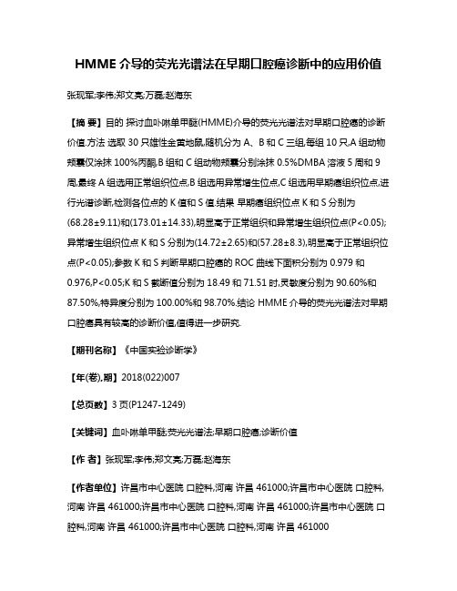
HMME介导的荧光光谱法在早期口腔癌诊断中的应用价值张现军;李伟;郑文亮;万磊;赵海东【摘要】目的探讨血卟啉单甲醚(HMME)介导的荧光光谱法对早期口腔癌的诊断价值.方法选取30只雄性金黄地鼠,随机分为A、B和C三组,每组10只,A组动物颊囊仅涂抹100%丙酮,B组和C组动物颊囊分别涂抹0.5%DMBA溶液5周和9周,最终A组选用正常组织位点,B组选用异常增生位点,C组选用早期癌组织位点,进行光谱诊断,检测各位点的K值和S值.结果早期癌组织位点K和S分别为(68.28±9.11)和(173.01±14.33),明显高于正常组织和异常增生组织位点(P<0.05);异常增生组织位点K和S分别为(14.72±2.65)和(57.28±8.3),明显高于正常组织位点(P<0.05);参数K和S判断早期口腔癌的ROC曲线下面积分别为0.979和0.976,P<0.05;K和S截断值分别为18.49和71.51时,灵敏度分别为90.60%和87.50%,特异度分别为100.00%和98.70%.结论 HMME介导的荧光光谱法对早期口腔癌具有较高的诊断价值,值得进一步研究.【期刊名称】《中国实验诊断学》【年(卷),期】2018(022)007【总页数】3页(P1247-1249)【关键词】血卟啉单甲醚;荧光光谱法;早期口腔癌;诊断价值【作者】张现军;李伟;郑文亮;万磊;赵海东【作者单位】许昌市中心医院口腔科,河南许昌 461000;许昌市中心医院口腔科,河南许昌 461000;许昌市中心医院口腔科,河南许昌 461000;许昌市中心医院口腔科,河南许昌 461000;许昌市中心医院口腔科,河南许昌 461000【正文语种】中文【中图分类】R739.8口腔癌是头颈部的常见肿瘤之一,包括牙龈癌、舌癌、口咽癌、上颌癌和唇癌等常见类型,其分型多数属于鳞状上皮细胞癌,即黏膜变异[1]。
- 1、下载文档前请自行甄别文档内容的完整性,平台不提供额外的编辑、内容补充、找答案等附加服务。
- 2、"仅部分预览"的文档,不可在线预览部分如存在完整性等问题,可反馈申请退款(可完整预览的文档不适用该条件!)。
- 3、如文档侵犯您的权益,请联系客服反馈,我们会尽快为您处理(人工客服工作时间:9:00-18:30)。
a rX iv:physics /049146v1[physics.atom-ph]28Se p24Hyperfine Spectroscopy of Optically Trapped Atoms A.Kaplan,M.F.Andersen,T.Gr¨u nzweig,and N.Davidson ‡Department of Physics of Complex Systems,Weizmann Institute of Science,Rehovot,Israel.Abstract.We perform spectroscopy on the hyperfine splitting of 85Rb atoms trapped in far-off-resonance optical traps.The existence of a spatially dependent shift in the energy levels is shown to induce an inherent dephasing effect,which causes a broadening of the spectroscopic line and hence an inhomogeneous loss of atomic coherence at a much faster rate than the homogeneous one caused by spontaneous photon scattering.We present here a number of approaches for reducing this inhomogeneous broadening,based on trap geometry,additional laser fields,and novel microwave pulse sequences.We then show how hyperfine spectroscopy can be used to study quantum dynamics of optically trapped atoms.1.Introduction The development of laser cooling and trapping techniques [1,2,3]has been motivated,to a great extent,by their potential use for precision measurements,of which precision frequency measurements are of outmost importance.Cold atoms are attractive for these measurements mainly because of the suppression of the Doppler broadening and because they allow for a longer interrogation time and hence a narrower linewidth.Modern atomic frequency standards are based on atomic clocks,which measure the frequency associated with the transition between two ground state hyperfine levels.The performance of such a clock can be improved by lengthening the time over which such a transition is measured.During the 1950’s various possibilities were suggested to lengthen this interrogation time:Ramsey [4]proposed confining the atoms in a storage ring with an inhomogeneous magnetic field,or a storage cell with properly coated walls.Zacharias [5]proposed to build an atomic “fountain”in which a thermal beam of atomsis launched upward,so slow atoms from the tail of the velocity distribution will turn around and fall back under the force of ing the Ramsey method of separated fields,the atoms could be interrogated once on their way up and then again on their way down,resulting in a long total interrogation time.Back then,this idea failed because of collisions of these slow atoms with the faster ing laser-cooled atoms,Zacharias’idea was revived in 1989by Kasevich et.al.[6].They cooled sodium atoms using a magneto-optical trap [7]and launched them on ballistic trajectories by applying a short pulse of resonant light.Two short πturned around inside a waveguide and allowed the ground-state hyperfine splitting to be measured with a linewidth of2Hz.To further increase the measurement time beyond the practical limit imposed by the height of a fountain,one can use trapped atoms,and in particular optical dipole traps,based on the dipole potential created by the interaction of a neutral atom and a laser beam[8,9].Unfortunately,the interaction between the trapping light and the trapped atoms is not negligible.First,even for a far-off-resonance trap,where many of the undesired effects of the atom-light interaction are suppressed,residual spontaneous scattering of photons from the trap laser destroys the ground state spin polarization or spin coherence[10].Next,and more importantly,atom trapping relies on inducing a spatial inhomogeneous shift of the atomic energy levels,and the existence of such a shift makes precision spectroscopy of trapped atoms a difficult task.In the case of hyperfine spectroscopy in optical traps,the inhomogeneity is approximately equal for both states,since the trapping light interacts with both levels with the same strength (the dipole matrix elements are identical).However,the difference in detuning between them results in a differential inhomogeneity,which induces a dephasing effect and, when ensemble-averaged,causes a broadening of the spectroscopic line and hence a loss of atomic coherence at a much faster rate than the spontaneous photon scattering rate [11].These effects can be reduced by increasing the trap detuning[11,12,13,14]and also by using blue-detuned optical traps,in which the atoms are confined mainly in the dark[11,15].However,the residual frequency shifts are still the main factor limiting the coherence of the trapped atoms,and hence the use of dipole traps for precision spectroscopy.A number of approaches for reducing the inhomogeneous broadening of the ground state hyperfine splitting of optically trapped atoms are presented in this tutorial. Following a brief review on light shifts and optical dipole traps in section2,and a description of the basic experimental setup in section3,we present in section4a simple,classical model for microwave spectroscopy in an optical trap,and use it to analyze the atomic coherence times for different trap geometries in section5.Based on this model,we present in section6a novel method for reducing the inhomogeneous frequency broadening by the addition of a weak lightfield,spatially mode-matched with the trappingfield and whose frequency is tuned in-between the two hyperfine levels.In section7we show another way of achieving long coherence times in an optical trap:a narrow energy distribution is achieved using a microwave“pre-selection”pulse which selects a subset of the atomic ensemble.Our technique allows the selection of a narrow energy band around any central energy enabling us to maximize the number of selected atoms(for a given energy width)by choosing the energy with the highest density of populated states.A full,quantum-mechanical model is developed in section8.The limit of short and strong pulses is further elaborated in section9,and used to predict the Ramsey decoherence time of a thermal ensemble as a consequence of dephasing.In section 10it is shown that,for certain trap parameters,the dephasing can be reversed bystimulating a“coherence echo”.The failure of the echo for other trap parameters is due to dynamics in the trap,and thereby“echo spectroscopy”can also be used to study quantum dynamics in the trap even when more than106states are thermally populated, and to study the crossover from quantum dynamics to classical dynamics.We then show (in section12)that the decay in the hyperfine coherence due to interactions with the environment,is only partly suppressed by echo spectroscopy,primarily due to dynamical (time-dependent)dephasing mechanisms.An improved pulse sequence is demonstrated, containing additionalπpulses for which the decay of coherence is reduced by a factor 2.5beyond the reduction offered by the simple echo scheme.Finally,in section13we show that our echo spectroscopy methods enable us to study quantum dynamics of trapped atoms also for chaotic and mixed dynamics where, surprisingly,partial revivals of atomic coherence occur in the perturbative(quantum) regime,and disappear in the non-perturbative(semi-classical)regime,indicating a clear quantum to classical transition as a function of the perturbation strength.2.Light Shifts and Dipole TrapsThroughout the work presented in this tutorial we use far-off-resonance optical dipole traps,which are traps based on the dipole potential created by the interaction of a neutral atom and a laser beam[9].A few concepts on which the rest of the work presented here is based,are reviewed.In sections2.1and2.2a brief review of the origin of the dipole potential,and its connection with the ac Stark shift of the ground-state is presented using an idealized two-level atom.In section2.3a short review on the use of the dipole potential to trap neutral atoms is given§.In sections2.4and2.5,a description of the main mechanisms for atomic decoherence is given,this time for multi-level atoms.2.1.The Optical Dipole PotentialThe interaction of a neutral atom and a nearly-resonant electro-magneticfield is governed by the dipole interaction,and is usually separated into two terms which correspond to a reactive force and a dissipative force.When an atom is exposed to light,the electricfield component induces a dipole moment in the atom,oscillating at the driving-light frequency.If we assume for example a monochromatic lightfield with an electricfield given by E( r,t)=ˆe E( r)e−iωL t+c.c.,whereˆe is the unit polarization vector andωL the frequency,then the dipole moment is d( r,t)=ˆe d( r)e−iωL t+c.c..The amplitude of the dipole moment is related to the amplitude of thefield by d=αE,whereαis the atomic complex polarizability,which is a function of the driving frequency.The interaction of the induced dipole moment with the drivingfield gives rise to the potential[9]U dip=−12ǫ0cRe(α)I( r),(1)§Laser-cooling of the atoms is a prerequisite for dipole trapping,and is done with techniques that have became standard in many research laboratories,and will not be reviewed here(See Refs.[16,17,18]).where I=2ǫ0c|E|2is the light intensity.The reactive“dipole”force is a conservative one,and is equal to the gradient of the above potential.The dissipative force is related to the power the oscillating dipole absorbs from thefield,which is given by:P diss= ˙ d E =ωLωL =12ln 1+I/I02 I/I02ω30γ2 ω30 γ(a)(c)(b)Figure 1.Dressed state picture of a two-level atom coupled by a light field withfrequency below the atomic resonance.(a)The energy levels form a ladder of (almostdegenerate)manifolds separated by the photon energy ωL .The atom-field interactionseparates the levels within each manifold by Ω′,where Ω′is the effective Rabifrequency.The eigenstates of the coupled system are a mixture of the eigenstatesof the uncoupled system.(b)If Ω≪|δ|,then the dressed eigenstates can be identifiedwith the original ground and excited states,with a small portion of the other state.Theenergy shift is Ω2/4δ.(c)A spatially inhomogeneous light field produces a ground-state potential well,in which the atom (shown schematically for a Gaussian trap)canbe trapped.and the laser field by H L = ωL a †a +1E i −E j .(10)The interaction term in our case is H AL =−ˆd ·E ,where ˆd =−e ˆr is the electric dipoleoperator.This interaction term couples states within the same manifold with a matrix element given bye,n −1|H AL |g,n =Ωgiven by[18]|1(n) =cosθ|e,n−1 −sinθ|g,n (12)|2(n) =sinθ|e,n−1 +cosθ|g,n ,(13) where tan2θ=−Ω/δ.The new(dressed)levels are separated by an energy Ω′, whereΩ′=√8δI2ω30γγs =δspontaneous scattering of photons is greatly reduced.A comprehensive review of the different schemes and applications of such optical dipole traps is presented in reference [9].In the limiting case where the frequency of the trapping light is much smaller then the atomic resonance,trapping is still possible,practically with no photon scattering [22].Such a quasi-electrostatic trap,formed by two crossed CO2laser beams,was used to create a Bose-Einstein condensate without the use of magnetic traps[23].Apart from using far-off-resonance lasers,the interaction between the lightfield and the atoms can be reduced by the use of blue-detuned traps,in which atoms are confined mostly in the dark[15].Experimentally,blue-detuned traps,which require surrounding a dark region of space with a repulsive dipole potential,are harder to realize than red-detuned ones,where already a single focused beam constitutes a trap[8].Several configurations for far-detuned dark optical traps were demonstrated,in which gravity provided the confinement in one direction:“Light sheets”traps were generated by elliptically focusing two laser beams and overlapping the two propagating light sheets to form a“V”cross-section that supports against gravity,while the confinement in the laser propagation direction is provided by the beam divergence[11].In a later work,and in order to achieve larger trapping volume,a different trap was constructed with four light sheets producing an inverted pyramid[24].A single beam trap was demonstrated using two axicons and a spherical lens to generate a conical hollow beam propagating upwards [25].Such gravito-optical traps are limited to weak confinement.Traps in which light provided the confinement in all directions were developed with hollow guerre-Gaussian“doughnut”modes were used,together with additional plug-in beams,to form such a trap[26].Several dark traps based on a single laser beam were demonstrated,providing grater experimental simplicity and enabling dynamical changes of the trap geometry and strength.As opposed to the2D case,were any desired light distribution can be generated using diffractive or refractive optical elements,there is no simple procedure to design an arbitrary3D light distribution[27,28].Nevertheless,through the use of refractive and holographic optical elements,it is possible to produce light distributions which are suitable for trapping atoms in the dark using a single laser beam.Such light distributions,which comprise of a dark volume completely surrounded by light,were realized using either combinations of axicons and spherical lenses,diffractive optical elements,or rapidly scanning laser beams.In thefirst scheme realized,the trapping beam was produced by passing a Gaussian beam through a phase plate of appropriate size,which shifted the optical phase at the center of the beam byπradians.Interference leads to a dark volume at the focus of the lens,surrounded by light in all directions[29].An additional method,with a much larger volume and more symmetric shape,was realized by simultaneously focusing two diffraction orders of a properly designed binary phase element,consisting of concentric phase rings with aπ-phase difference between subsequent rings[30].An improved trap configuration was demonstrated by adding an axicon telescope before the phase element of the above setup[31].This configuration maximizes the trap depth for a given laserpower and trap dimensions,and greatly reduces the light induced perturbations to the trapped atoms.A related scheme was demonstrated in references[32]and[33].Finally, a tightly-focused rapidly-rotating laser beam was used to create a trap[34].If the scan frequency is high enough,the optical dipole potential can be approximated as a time averaged quasi-static potential.For a blue-detuned laser beam,and a radius of rotation larger than the waist of the focussed beam,a dark volume suitable for3D trapping is obtained.2.4.Photon Scattering and Coherence Relaxation in Multi-Level AtomsThe dipole potential can be viewed as originating from cycles of absorption of a photon and stimulated emission into a different laser mode.This process is unfortunately accompanied by spontaneous scattering,in which the absorption is followed by spontaneous emission in a random direction.Spontaneous scattering is one of the main limiting mechanism for the atomic hyperfine coherence .Spontaneous scattering is a two-photon process,in which an atom initially at a state|F,m F absorbs a photon from the trap laser and moves to an intermediate state |F′,m′F of some excited level.The atom then decays back to the ground state,to afinal state|F′′,m′′F .If F′′=F and m′′F=m F,the process is called“Rayleigh scattering”. Otherwise,it is denoted“Raman scattering”.Clearly,Raman events destroy the atomic state coherence and hence are detrimental to the spectroscopy.As will be discussed below in section12,also Rayleigh scattering events can be destructive for spectroscopy of a trapped ensemble.The probability amplitude for scattering between|F,m F and|F′′,m′′F ,via an intermediate state|F′,m′F is proportional to F′′,m′′F|µk|F′,m′F F′,m′F|µj|F,m F , whereµk(µj)are the spherical components of the dipole moment operator(k,j=−1,0 or1depending on the polarization of the absorbed and emitted photons).If the detuning from resonance is large enough such that no specific intermediate state is resolved,then to calculate the rate of transitionsγF,mF→F′′,m′′F between|F,m F and|F′′,m′′Fthe amplitudes for all possible paths must be summed.For rubidium atoms,these are the two excited states52P1/2and52P3/2,with all their different hyperfine levels and corresponding Zeeman sub-levels.We further assume that the laser polarization is linear, hence conservation of angular momentum dictates m F=m′F.The total transition rate is[10]γF,mF→F′′,m′′F =3πc2ω3L Iδ1+α(2)F,m F→F′′m′′FFigure 2.Calculated total scattering rate(dashed line)and F-changing Ramanscattering rate(full line)for85Rb atoms and linear polarization.The former affects thecoherence time of trapped atoms,but the later is experimentally simpler to measure. whereα(J)F,m F→F′′,m′′F =γJmost spontaneous scattering events leave the internal state of the atom unchanged.2.5.Light Shifts and Dephasing in Multi-Level Atoms For a real multi-level atom,the light-shifts described in section 2.2depend,in general,on the particular substate of the atom.The equivalent of equation 14in the case of a multi-level atom can be written using the dipole matrix elements µij = e i |µ|g i between a specific ground state |g i and a specific excited state |e j .Using µij =c ij µ ,we can write the ac Stark shift for a ground state |g i as [9]:∆E i =3πc 2γδij ,(18)The summation takes into account the contributions of the different coupled excited levels |e j ,each with its respective transition coefficient c ij ,and detuning δij =ω−ωij .If the detuning of the light is large as compared to the excited state hyperfine splitting ω′HF ,then certain sum rules exist for the transition coefficients [35]and equation 18for the shift of a ground state with total angular momentum F ,simplifies to:∆E F =πc 2γI δ1,F +21−ǫ2 1δ2,F ,(19)where ǫis the light polarization ellipticity and δ1,F [δ2,F ]is the detuning of the laser from the D 1[D 2]line.For linearly polarized light (ǫ=1)∆E F (r )=3πc 2γδ∗F ,(20)where13 2δ2,F −∆F (21)is the “weighted detuning”(below,we drop the “∗”and call this the detuning).Note,that the interaction matrix elements are identical for atoms in |F =2 and |F =3 .However,the light shift is inversely proportional to the trap laser detuning,which differs by ωHF ,and therefore the potential from a far-detuned laser is slightly different for thetwo hyperfine levels.Loosely speaking,this difference in potential means that different hyperfine states “feel”different trap shapes.For microwave spectroscopy of a thermal ensemble this results in a rapid decay of the ensemble-averaged spectroscopic signal as a consequence of dephasing,much faster than the decay due to spontaneous scattering of photons.3.Experimental SetupAll the experiments described in this tutorial consist of three stages.During the first stage standard laser-cooling techniques are used to cool an ensemble of 85Rb atoms and load a portion of them into a far-off-resonance trap.During the second stage,all the nearly-resonant laser beams are shut-offleaving only the far-off-resonance trappingbeam on,and microwave pulses are applied.In last stage short pulses of on-resonance beams are used for the diagnostics.In this section,a detailed description of the above steps is provided.ser Cooling and TrappingThe heart of our setup is a vacuum chamber connected to a small reservoir of rubidium atoms through a valve.The chamber has six big windows used for the laser beams, and two additional small windows used for imaging the atomic cloud with an intensified CCD camera and measuring thefluorescence signal with a photomultiplier tube(see figure3).Thefirst step in all the experiments described here is a magneto-optical trap(MOT) [7].The MOT laser beams consist of three orthogonal pairs of counter-propagating beams,detuned approximately−17MHz(=−2.8γ)from the 5S1/2,F=3 → 5P3/2,F′=4 line,and a“repumping”beam in resonance with 5S1/2,F=2 → 5P3/2,F′=2 .A pair of water-cooled copper coils in the anti-Helmholtz configuration provide the magneticfield gradient for the MOT(seefigure3).In addition,three orthogonal Helmholtz coils are used to compensate for constant magneticfields.The MOT loading time is∼700ms.After that a∼50ms temporal dark MOT stage[12]is applied in order to increase the spatial density of the atoms.The intensity of the MOT beams is reduced to∼1.5mW cm−2,their detuning increased to∼−30MHz, the magneticfield gradient increased to8G cm−1,and the repump intensity reduced by a factor of40.Final optimization of these parameters is performed by optimizing the number of atoms loaded into the dark optical trap.A peak density of∼1×1011cm−3 is achieved for optimized parameters,but typically we work at lower densities,for which collisions are negligible for the timescales of our experiments.The laser cooling stage ends with a polarization-gradient cooling stage[36],in which the magneticfield is set to zero,the MOT beams intensity are further decreased and their detuning increased. Usually,3ms of this cooling stage result in a temperature of∼10−20µK.The dipole trap in our experiments consists of a linearly polarized horizontal Gaussian laser beam with wavelength in the rangeλ=785−810nm.The trap beam is coupled into a single modefiber,and the output of thefiber(with power in the range P=50−400mW)is focused to a w0∼50µm spot at the center of the vacuum chamber. An active servo circuit and an acousto-optic modulator ensure a1%stability in the beam power,and hence in the trap depth.With typical values of P=50mW andλ=800nm we achieve a trap with a depth of∼35µK,and oscillations frequenciesωr=2.3KHz andωz=8.4Hz in the radial and axial dimension,respectively.The clear separation of time-scales between the fast transverse oscillations and the very slow longitudinal ones is used in the analysis of some of our experiments to neglect the longitudinal motion, which is essentially frozen during the duration of the experiment,and hence to treat the system as a two-dimensional one.The trap beam overlaps the center of the atomic cloud during the cooling stagesFigure3.Basic components of the experimental setup.The MOT beams consistsof three orthogonal pairs of counter-propagating beams,and a repumping beam.Twocopper coils in the anti-Helmholtz configuration provide the magneticfield gradient,and three orthogonal Helmholtz coils are used to compensate for constant magneticfields.The atoms are imaged with an intensified CCD camera,and theirfluorescencemeasured with a photomultiplier tube.The dipole trap beam enters the chamber,co-propagating with the detection beam.The microwave pulses are created by asynthesizer,amplified and radiated into the chamber using an antenna.A biasmagneticfield is applied parallel to the trap’s polarization axis and to the microwavemagneticfield direction,in order to Zeeman shift the magnetic sensitive m F=0levelsout of resonance with the microwave pulse.and,after turning offall the lasers(with the exception of the trap)we end up with ∼105atoms loaded in the trap(depending on the specific power and detuning)with a temperature of∼20µK.At the end of this stage,the atoms are prepared in the F=2 ground state by turning on the MOT beams,without a repump beam[29],for1ms.3.2.Microwave SpectroscopyWe are interested in spectroscopy of the“clock”transition,i.e.theωHF=2π×3.032×109sec−1transition between the two magnetic insensitive hyperfine Zeeman substates of the ground state,|F=2,m F=0 and|F=3,m F=0 ,which we denote|↓ and |↑ .We drive this transition with a nearly-resonant microwavefield.The microwave pulses are created by a synthesizer(Anritsu,69317B),whose clock is connected to a high stability and low phase noise10MHz oscillator.The pulses are then amplified with a30dB amplifier(Mini-Circuits,ZVE-86)and irradiated into the chamber using a Log-periodic antenna.The strongest microwavefields produced in our setup correspond to a Rabi-frequency of5kHz for free(untrapped)atoms.A bias magneticfield is applied parallel to the trap’s polarization axis and to themicrowave magneticfield direction,in order to Zeeman shift the magnetic sensitive m F=0levels out of resonance with the microwave pulse.In most of the experiments (See sections6and10),its value is∼40−80mG.For the experiment in section12,it is∼240mG,but then a MOSFET switch is used to turn it on after the cooling stage, which requires a nearly zerofield.Special care is taken to align the directions of the microwave magneticfield and the bias magneticfield to be parallel to the trap’s laser magneticfield(i.e.the trap’s polarization is perpendicular to the biasfield),to enable a common well-defined quantization axis for all thefields interacting with the atoms.3.3.DiagnosticsFollowing the microwave pulses,N3(the population in F=3)is measured by detectingthefluorescence during a short pulse of a laser beam resonant with the cycling transition 5S1/2,F=3 → 5P3/2,F=4 .The population of F=2is then measured for thesame experimental run by turning on the repumping beam(which is resonant with 5S1/2,F=2 → 5P3/2,F=3 )and applying an additional detection pulse.This normalized detection scheme is insensitive to shot-to-shotfluctuations in atom number as well asfluctuations of the detection laser frequency and intensity[37].In addition to the population of|↑ by the microwavefield,|↑ and all sublevels of F=3are in general populated by spontaneous scattering of photons from the trapping laser,which always accompanies the dipole potential and tends to destroy the atomic coherence(see section2).A simple way to measure the amount of photon scattering is by measuring the spin relaxation caused by spontaneous Raman scattering[10,29]. This is a very useful experimental technique which enables to measure even very low scattering rates.For this measurement,the trapped atoms arefirst prepared in the lower hyperfine level of the ground state,F=2.The number of atoms in F=3after a variable time t,N3(t),is measured by detecting thefluorescence after a short pulse of a resonant laser beam.The fraction of Raman scattering events out of the total photon scattering events can be calculated using the known matrix elements for the transition,and therefore the total amount of photon scattering can be inferred from the spin relaxation measurement(see section2.4).We calculate the microwave driven part of the population by subtracting from the measured signal the above contribution due to F-changing Raman transitions induced by the trap laser and normalize to the signal after a shortπ-pulse,which transfers the whole population of|↓ to|↑ .The corrected and normalized signal is denoted P↑.4.Microwave Spectroscopy in a Dipole Trap:A Classical ModelWe drive the magnetic-insensitive transition with a nearly-resonant microwavefield,and apply a static magneticfield in order to shift all other(magnetic sensitive)levels out of resonance.In such case,and neglecting for the moment the effects of the trap on the atoms,we can consider a two-level system,separated in energy by E HF= ωHF.Figure4.Rabi spectrum of free atoms with a25ms microwave pulse,showing thecharacteristic“sinc2”lineshape corresponding to a rectangular pulse.Note that sincethe population of the four|F=2,m F=0 states is included in N↑/(N↓+N↑),a valueof0.2represents the maximal possible signal(aπpulse)for the|F=2,m F=0 →|F=3,m F=0 transition.When a free(untrapped)atom,initially in state|↓ ,is placed in a microwavefield with frequencyωMW the probability offinding it in state|↑ as a function of time is:P↑=Ω2MW2t ,(22)whereΩMW is the Rabi frequency of the microwavefield,Ω′MW=2pulse)puts the atoms in a quantum superposition of bothstates.During free evolution,due to the detuning of the drivingfield from resonance, these two states develop a relative phase in the rotating frame of thefield.The secondπ2+1ω30ωHF1− ωHF2,i.e.forδ2,F=2andδ2,F=3both positive(or both negative),the ground state energy splitting is always reduced by the presence of a lightfield.When the detuning is“between”the hyperfine levels,|δ|<ωHF2equation25yieldsωHF(r)−ωHF≈ ωHF ,(26) where U(r)is the spatially dependent dipole potential that forms the trap.The fact that the relative ac Stark shift isωHF δsmaller than the dipole potential,is the main motivation for using far-off-resonance traps for precision spectroscopy.For example in reference[11]the relative ac Stark shifts were onlyωHF δ≈2·10−4times the dipole potential.。
