72 7120 AC&DC高压测试仪操作指导书
ac7120标准
ac7120标准
AC7120是一个无线网卡驱动程序的标准,它通常用于支持各种无线网络接口,包括WiFi、蓝牙和移动宽带等。
该标准通常由设备制造商提供,以确保其无线网卡与操作系统和其他硬件的兼容性。
具体来说,AC7120标准是一个通用的无线网卡驱动程序标准,旨在提供与各种操作系统和硬件平台的兼容性。
它旨在确保无线网卡可以与操作系统无缝集成,并提供稳定、高效的网络连接。
值得注意的是,AC7120标准并不是一个具体的硬件规格或技术规范,而是一种通用的驱动程序标准。
因此,不同的设备制造商可能会根据该标准提供不同的实现和性能特性。
因此,在选择无线网卡时,建议查看制造商提供的具体规格和性能数据,以确定最适合您需求的解决方案。
思科 Meraki MR72 802.11ac 无线访问点说明书

High performance cloud-managed 802.11ac wirelessThe Cisco Meraki MR72 is a three–radio, cloud-managed 2x2 MIMO 802.11acaccess point. Designed for general purpose next-generation deployments in harshoutdoor locations and industrial indoor conditions, the MR72 provides performance,security, and manageability.The MR72 provides a maximum 1.2 Gbps data rate with concurrent 802.11ac and802.11n 2x2:2 MIMO radios, and security and spectrum visibility via a third radiodedicated to 24x7 WIDS/WIPS and automated RF optimization. An integratedBluetooth low energy (BLE) radio delivers Beacon functionality and BLE devicescanning.The combination of cloud management, 802.11ac, full-time RF environmentscanning, and an integrated Bluetooth technology delivers the high throughput,reliability, and flexibility required by the most demanding business applications likevoice and high-definition streaming video, both today and tomorrow.MR72 and Meraki cloud management: A powerful comboThe MR72 is managed through the Meraki cloud, with an intuitive browser-basedinterface that enables rapid deployment without training or certifications. Since theMR72 is self-configuring and managed over the web, it can even be deployed at aremote location without on-site IT staff.The MR72 is monitored 24x7 via the Meraki cloud, which delivers real-time alertsif the network encounters problems. Remote diagnostics tools enable real-timetroubleshooting over the web, meaning multi-site, distributed networks can bemanaged remotely.The MR72’s firmware is always kept up to date from the cloud. New features, bugfixes, and enhancements are delivered seamlessly over the web, meaning nomanual software updates to download or missing security patches to worry about. Product Highlights• Ideal for outdoor and industrial indoor environments • 2x2:2 802.11ac, 1.2 Gbps aggregate dual-band data rate • 24x7 real-time WIPS/WIDS and spectrum analytics via dedicated third radio• Integrated Bluetooth low energy Beacon and scanning radio • Forms point-to-point links with optional sector antennas • Self-healing, zero-configuration mesh• Integrated enterprise security and guest access• Application-aware traffic shaping• Self-configuring, plug-and-play deploymentMR72Dual-band 2x2 MIMO 802.11ac Access Pointwith dedicated security and RF optimization radio and Bluetooth low energy Beacon and scanning radioFeaturesAggregate data rate of up to 1.2 GbpsA 5 GHz 2x2:2 802.11ac radio and a 2.4 GHz 2x2:2 802.11n radio offer a maximum combined aggregate dual-band data rate of 1.2 Gbps. Technologies like transmit beamforming and enhanced receive sensitivity allow the MR72 to support a higher client density than typical enterprise-class access points, resulting in fewer required APs for a given deployment. Band steering further enhances overall throughput, by moving 5 GHz-capable clients to the 5 GHz radio, maximizing the capacity in the 2.4 GHz range for older 802.11b/g clients.Rugged industrial designThe MR72 is designed and tested for salt spray, vibration, extreme thermal conditions, shock and dust and is IP67 rated, making it ideal for extreme environments. Despite its rugged design, MR72 has a low profile and is easy to deploy.Third radio dedicated to security and RF optimizationThe MR72’s sophisticated, dedicated dual-band third radio scans the environment continuously, characterizing RF interference and containing wireless threats like rogue access points. No more need to choose between wireless security, advanced RF analysis, and serving client data: a dedicated third radio operates without any impact to client traffic or throughput.Bluetooth low energy Beacon and scanningAn integrated Bluetooth low energy radio provides seamless deployment of BLE Beacon functionality and effortless visibility of BLE devices within range of the AP. The MR72 enables the next generation of location-aware engagement right out of the box. Automatic cloud-based RF optimizationThe MR72’s sophisticated, automated RF optimization means that there is no need for the dedicated hardware and RF expertise typically required to tune a wireless network. The real-time full-spectrum RF analysis data collected by the dedicated third radio is continuously fed back to the Meraki cloud. The Meraki cloud then automatically tunes the MR72’s channel selection, transmit power, and client connection settings for optimal performance under the most challenging RF conditions.Secure wireless environments using 24x7 Air MarshalNo longer choose between a wireless intrusion prevention system (WIPS) and serving client data: thanks to the dedicated third radio, Air Marshal, a highly optimized built-in WIPS, scans continuously for threats and remediates them as commanded, all without disrupting client service. Alarms and optional auto-containment of rogue APs are configured via flexible remediation policies, ensuring optimal security and performance in even the most challenging wireless environments.Integrated enterprise security and guest accessThe MR72 features integrated, easy-to-use security technologies to provide secure connectivity for employees and guests alike. Advanced security features such as AES hardware-based encryption and WPA2-Enterprise authentication with 802.1X and Active Directory integration provide wire-like security while still being easy to configure. One-click guest isolation provides secure, Internet-only access for visitors. Our policy firewall (Identity Policy Manager) enables group or device-based, granular access policy control.Application-aware traffic shapingThe MR72 includes an integrated layer 7 packet inspection, classification, and control engine, enabling you to set QoS policies based on traffic type. Also included is integrated support for Wireless Multi Media (WMM), 802.1p, and DSCP. Prioritize your mission critical applications, while setting limits on recreational traffic, e.g., peer-to-peer and video streaming.High performance meshThe MR72’s advanced mesh technologies, like multi-channel routing protocols and multiple gateway support, make it possible to cover hard-to-wire areas and improve network resilience. In the event of a switch or cable failure, the MR72 will automatically revert to mesh mode.Self-configuring, self-optimizing, self-healingWhen plugged in, the MR72 automatically connects to the Meraki cloud, downloads its configuration, and joins the appropriate network. The MR72 then self-optimizes, determining the ideal channel, transmit power, and client connection parameters. As necessary, it will also self-heal, responding automatically to switch failures and other errors.Recommended Use CasesOutdoor coverage for high client-density corporate campuses, educational institutions, metro Wi-Fi, and parks• Provide high-speed access to a large number of clients• Point-to-multipoint mesh Indoor coverage for industrial areas(e.g., warehouses, manufacturingfacilities)• Reliable coverage for scanner guns,security cameras, and POS devices• High speed-access for iPads, tabletsand laptopsZero-touch point-to-point links• Build a long-distance bridge betweentwo networks• Extend hotspot networks via mesh whilesimultaneously serving clientsSpecificationsRadiosOne 2.4 GHz 802.11b/g/n, one 5 GHz 802.11a/n/ac, one dedicated for dual-band WIPS & spectrum analysis, and one dedicated to Bluetooth low energy (2.4 GHz)Concurrent operations of all radiosMax data rate 1.2 Gbit/sOperating bands:FCC (US) CE (Europe)2.412-2.484 GHz 2.412-2.484 GHz5.150-5.250 GHz (UNII-1) 5.150-5.250 GHz (UNII-1)5.725 -5.825 GHz (UNII-3) 5.250-5.350 GHZ (UNII-2)5.470-5.600, 5.660-5.725 GHz (UNII-2e)802.11ac and 802.11n Capabilities2 x 2 multiple input, multiple output (MIMO) with two spatial streamsMaximal ratio combining (MRC)Beamforming20 and 40 MHz channels (802.11n), 20, 40, and 80 MHz channels (802.11ac)Packet aggregationPowerPower over Ethe rnet: 37 - 57 V (802.3af compatible)Power consumption: 13.87 W max (802.3af)Power over Ethernet injector sold separatelyMountingMounts to walls and vertical poles.Mounting hardware includedPhysical SecuritySecurity screw includedKensington lock hard pointAnti-tamper cable bayConcealed mount plateEnvironmentOperating temperature: -40 °F to 140 °F (-40 °C to 60 °C)IP67 environmental ratingPhysical Dimensions10.1” x 6.22” x 3.3” (256 mm x 158 mm x 83 mm) including mounting bracket Weight: 3.1 lbs. (1.4 kg)Interfaces 1 x 100/1000Base-T Ethernet (RJ45)Four external N-type female antenna connectorsSecurityIntegrated policy firewall (Identity Policy Manager)Mobile device policiesAir Marshal: Real-time WIPS (wireless intrusion prevention system) with alarmsRogue AP containmentGuest isolationTeleworker VPN with IPsecPCI compliance reportingWEP, WPA, WPA2-PSK, WPA2-Enterprise with 802.1XTKIP and AES encryptionVLAN tagging (802.1q)Quality of ServiceAdvanced Power Save (U-APSD)DSCP802.1pLayer 7 application traffic shaping and firewallMobilityPMK and OKC credential support for fast Layer 2 roamingL3 roamingLED Indicators1 power/booting/firmware upgrade statusRegulatoryRoHSFor country-specific regulatory information, please contact Meraki salesWarranty1 year hardware warranty with advanced replacement includedOrdering InformationMR72-HW Meraki MR72 Cloud Managed 802.11ac APMA-INJ-4-XX Meraki 802.3at Power over Ethernet Injector (XX = US/EU/UK/AU) MA-ANT-20 Meraki Dual-Band Omni AntennasMA-ANT-21 Meraki 5 GHz Sector AntennaMA-ANT-23 Meraki 2.4 GHz Sector AntennaMA-ANT-25 Meraki Dual-Band Patch AntennaNote: Meraki Enterprise license required.RF Performance Table* Maximum hardware capability shown above. Transmit power is configurable in increments of 1 dB and is automatically limited to comply with local regulatory settings.。
7201使用说明书-简字

2)输入信号(18 点) ‧DC24V 电流输入(10mA,同步式,光耦合器绝缘)
開始、停止、歸零要求、皮重消除要求、皮重解除要求、總重/ 淨重切換、保留/排出、判定、印表、代碼 1、代碼 2、代碼 4、 代碼 8、代碼 10、代碼 20、代碼 40、代碼 80
BCD 平行输出(TTL 水准) BCD 平行输出(达林顿) 外部数字码开关输入用 序列发生器连结输入用 4~20mA 模拟输出 绝缘型 RS422/485 继电器输出入
2)选配打印机 打印机 KJ.特长 : 1)高速 A/D 转换 A/D 转换速度约 100 次/秒,分解能 1/1,000,000 的高分解能。 把定量、定量前等之设定值与重量值的比较与 A/D 转换速度同步进行,所 以可进行高速的重量变化之下也可做到正确性的计量制度。 1)数字校正 不使用倾角开关与电位器等,以全面的按键操作,采用可轻易进行归零调整、跨距调整 之数字校准方式。
6
2.3 显示部 1)重量显示 7 段 LED(高亮度红色),6 位(纵:13.6mm) 2)设定显示部 7 段 LED(高亮度绿色),9 位(纵:8mm) 选择显示、项目 LED 显示灯(11 个 LED)
累計、日期、項目、扣皮重、補正、定量、定量前/HH、過量/H、 不足/L、定量前 2/設定 LL、落差 3)状态显示 LED
7
2.5 设定值的记忆
初始设定
:EEPROM
99 种设定值内存
:CMOS SRAM(电池辅助)
时间、扣重与归零、累计资料的内存:CMOS SRAM(电池辅助)
关于同步晶体时钟型号72系列的商品说明书

*******************SynchronousQuartz–7 Day Carry-Over**Switch Minimum Event WithoutWith 3 Way Input Rating On/Off On/Off Override Override With 3 Way OverrideVoltage 250V Res.Time Time Time ControlsSTuZ–24STuZH–24QTuZH–2424VAC SPDT 21A 15 min.ON 1/4 hr.STuZ–120STuZH–120QTuZH–120120VAC SPDT 21A 15 min.ON 1/4 hr.STuZ–240STuZH–240QTuZH–240208/240VACSPDT 21A 15 min.ON 1/4 hr.STuZH–277*277VAC SPDT 21A 15 min.ON 1/4 hr.SWuZ–24SWuZH–24QWuZH–2424VAC SPDT 21A 2 hr.ON 2 hr.SWuZ–120SWuZH–120QWuZH–120120VAC SPDT 21A 2 hr.ON 2 hr.SWuZ–240SWuZH–240QWuZH–240208/240VAC SPDT 21A 2 hr.ON 2 hr.SWuZH–277*277VAC SPDT 21A 2 hr.ON 2 hr.**Quartz units also operate on DC voltages down to 12VDCELECTROMECHANICAL TIME CONTROLSM I L 72 Series24 Hour, 7 Day• Synchronous drive or quartz drive withb a t t e r y backup• 21A SPDT switch• Captive trippers with interval as low as15 minutes• With or without 3-way overr i d e• Real clock face7Captive Trippers are easy to set,can’t be lost.7Up to 48 (24 hr.) or 42 (7 day) on/off events.7Authentic clock face with hour and minute hands on both 24 hr.and 7day models.7Surface,flush (panel) or DIN rail mount-ing.7Synchronous drive for greatest accuracy and lowest cost.7Quartz drive for 7 day carryover with rechargeable battery.7Three-way OFF/AUTO/ON over-ride switch provides continuous override (not reset at next timed event).7UL recognized,CSA listed.SPECIFIERS GUIDE Furnish and install a Grasslin MIL 72____ 24 hour (7 day) time switch with 15 min.(2 hour) interval captive trippers and quartz (synchronous) drive.Input voltage shall be 120V (24V, 240V, 277V) and SPDT switch contacts shall be silver cadmium oxide ratedat21A,resistive,***********************************************indication, the unit shall incorporate an authentic clock face.Installation for surface,(flush, DIN rail or within indoor or outdoor enclosure) mounting.Time switch shall contain an OFF/AUTO/ON override.For Carry-over:The time controls shall have a quartz drive with 7 day reserve carry-over from a rechargeable battery.SPECIFICATIONSSize:MIL 72A:2.83" x 4.0" x 2.06"MIL 72E:2.83" x 2.83" x 1.36"Power Consumption:1VASwitch:SPDT dry contacts, silver cadmium oxideSwitch Rating:21A 250V Resistive1350 Watts T ungsten1HP @ 120V2HP @ 240V16FLA, 96LRA–120VAC12FLA, 72LRA–240VACMinimum Switching Current:100ma, 20VAmbient Temperature Range:–40°F to 180°F synchronous units–14°F to 131°F quartz unitsWiring Connections:Screw Terminals Suitable for #10 to #24AWGINSTALLATIONStand Alone:With indoor or outdoor enclosurePa n e l :S u r f a c e , flush, or DIN rail mounting ORDERING DATAIN OPTIONAL ENCLOSURES UL FILE:E83486CSA FILE:LR52379Complete Model Number = MIL 72A or E followed by suffix code and voltageExample:MIL 72A STuZ–24MIL 72A–Surface MountMIL 72E–Flush Mount7 DAYTIME CONTROL MIL 72A–Surface Mount MIL 72E–Flush Mount 24 HOUR TIMECONTROLDigi 42/2 – 120†120V, 50/60Hz Flush or Surface 42294(2) SPDT, 16A, 250VAC Digi 42/2 – 240†240V, 50/60Hz Flush or Surface 42294(2) SPDT, 16A, 250VAC Digi 42/2 – 24†24V, 50/60Hz Flush or Surface 42294(2) SPDT, 16A, 250VACELECTRONIC TIME CONTROLS, 2 CHANNELDigi 42/224 Hour, 7 Day• T wo channel or double pole switching• Automatic daylight time changeover• 8th day HOLIDAY pro g r a m• 16A, SPDT switching724 hour or 7 day programming with resolution to them i n ute and accuracy to the second.7L a r ge keys easep r o g r a m m i n g .7Unique circular programming patternand minimal steps simplify pro g r a m m i n g .7Au t o m a t i cD a ylight Time ch a n g e o ver in spring and fall eliminatesneed to manu a l l y ch a n g e the time.7H o l i d a y,or “8t hd a y ”p r ogram may be scheduled a week in advance fo rone or more da y s .7E a c h channel may be pro g r a m m e ds e p a r a t e l y,or both toge t h e r .7Au t o m a t i c a l l y rech a r ge dNiCad battery maintains program and display for twoweeks or more.7M a n ual override for each channel pro-vides for either temporary or continuous ON or OFFs t a t e ,with status displayed in large LCD.SPECIFIERS GUIDEF u r nish and install a Grasslin Digi 42/2 electronic time sw i t c h .This two channel con-trol shall have 24 hour and 7 day programming and also offer 21 ON and 21 OFF set-point programs and allow selection of any combination of days for different w e e k d a ys c h e d u l e s .The LCD shall display time of day in AM/PM or military time fo r mat andp r o vide load status indication.S e l e c t a b le automatic or manual daylight timec h a n g e o ver shall be pro v ide d .In automatic mode, the time switch shall automaticallya d v ance the time by 1 hour at 2AM on the first Sunday of April, and set back the time1 hour at 2AM on the last Sunday of October.The time switch shall be progra m m a b l eto the minute and also offer a manual ove r r ide for ON or OFF to the next scheduledevent or for permanent ON/OFF/Au t o .A 8th day or “H o l i d a y ”p r o g ram shall be pro-vided which may be activated to begin on a specific day up to a week in adva n c e , andc o n t i n ue from 1 to 99 day s , selectable by the user.The SPDT relay outputs will berated for 16A General Purp o s e , 1HP at 240V, and 16A General Purp o s e , 1/2HP at120V as well as pilot duty of 720VA .R e s e r ve shall be provided for a minimum of 14d a ys with a built-in rechargeable battery which need not be replaced.The time sw i t c hshall be surface or flush panel mountable with a DIN rail mounting base optional, orshall be ava i l a b le with a NEMA 1 indoor or NEMA 3R outdoor enclosure.SPECIFICATIONS Output Switches:Tw o SPDT relays with dry contacts Switch Capacity:16A General Purpose,125-250VAC 1000W T ungsten, 250V 500W Tungsten, 125V N.O.Contact:1HP, 240VAC;1/2HP, 120VAC Pilot Duty:720VA, 120-240VAC N.C.Contact:3/4HP, 240VAC;1/3HP, 120VACPilot Duty:360VA, 120-240VAC Input Power:4.4VA Shortest Switching Time:1 minute Accuracy:Less than ±4 minutes per year deviation Ambient T emperature:0°F to 140°F (–18°C to 60°C)Ambient Humidity:0 to 95% RH, non-condensing Selectable AM/PM or 24 hr.(military) time display Selectable completely automatic or one key manual daylight time changeover Manual 3-Way Override:Temporary or permanent ON or OFF;status indication in LCD display Wiring Connections:Screw terminals #12 to #24AWG Size:2.83”x 2.83”square face, x 2.28”deep UL and Canadian UL Recognized:File E83486ORDERING DATA*******************Time Controls Digi 20A – 120120V, 50/60HzSurface or DIN Rail 20140SPDT, 16A, 250V Digi 20A – 240208/240V, 50/60Hz Surface or DIN Rail 20140SPDT, 16A, 250V Digi 20A – 2424V, 50/60Hz Surface or DIN Rail 20140SPDT, 16A, 250V Digi 20A – 277*277V, 50/60Hz Surface or DIN Rail 20140SPDT, 16A, 250V Digi 42A – 120†120V, 50/60Hz Surface or DIN Rail 42294SPDT, 16A, 250V Digi 42A – 240†208/240V, 50/60Hz Surface or DIN Rail 42294SPDT, 16A, 250V Digi 42A – 24†24V, 50/60Hz Surface or DIN Rail 42294SPDT, 16A, 250V Digi 20E – 120120V, 50/60Hz Flush Panel 20140SPDT, 16A, 250V Digi 20E – 240208/240V, 50/60Hz Flush Panel 20140SPDT, 16A, 250V Digi 20E – 2424V, 50/60Hz Flush Panel 20140SPDT, 16A, 250V Digi 20E – 277*277V, 50/60Hz Flush Panel 20140SPDT, 16A, 250V Digi 42E – 120†120V, 50/60Hz Flush Panel 42294SPDT, 16A, 250V Digi 42E – 240†208/240V, 50/60Hz Flush Panel 42294SPDT, 16A, 250V Digi 42E – 24†24V, 50/60Hz Flush Panel 42294SPDT, 16A, 250VELECTRONIC TIME CONTROLS, 1 CHANNEL ORDERING DATAFile #E83486Digi 20, Digi 42 Series24 Hour, 7 Day• Automatic Daylight Ti m echangeover with Digi 42• Holiday program with Digi 42• Rechargeable battery backupwith 1 week or more carry o v e r• 16 amp, SPDT switching724 hour or 7 day programming with accuracy to thesecond.7Easy programming;minimal keys and pro-gramming steps.7Unique “Circular Programming”withlarge keys is easier to use.7Selectable blocks of week-days or weekends for quick programming on Digi 20,any combination of days on Digi 42.7Holiday programon Digi 42 may be scheduled a week in advance for oneor more days.7Automatically recharged NiCad batterymaintains program and display for one week or more.7Manual override provides for either temporary or con-tinuous ON or OFF state,with status displayed in largeLCD.SPECIFIERS GUIDEFurnish and install a Grasslin Digi 20 (Digi 42) electronic time switch.This 1 circuit con-trol shall have 24 hour and 7 day programming and also offer 10 (21) ON and 10 (21)OFF setpoint programs and include 4 block programs (allow selection of any combi-nation of days) for different weekday schedules.The LCD shall display time of day inAM/PM or military time format and provide load status indication.A daylight timeadjustment key shall also be provided.The time switch will be programmable to theminute and also offer a manual override for ON or OFF to the next scheduled event orfor permanent ON/OFF/Automatic.(The Digi 42 shall provide a 8th day or “Holiday”program which may be activated to begin on a specific day up to a week in advance,and continue from 1 to 99 days, selectable by the user.) The SPDT relay output will berated for 16A Resistive @ 277V AC.Reserve shall be provided for a minimum of 7 dayswith built-in rechargeable batteries which need not be replaced.The time switch shallbe surface, DIN rail or flush mountable or shall be available with a NEMA 1 indoor orNEMA 3R outdoor enclosure.SPECIFICATIONS Digi 20Digi 42Channels 11Programs 2042Holiday Program No Y es Reserve Carryover;min. 1 week 2 weeks Automatic Spring/Fall Daylight Time Changeover No Yes TECHNICAL DATA Output:1 SPDT relay with dry contacts Switching Capacity:16A Resistive @ 277VAC 1000W Tungsten @ 240VAC Input Draw:4VA Shortest Switching Time:1 minute Accuracy:Less than ±4 minutes per year deviation Ambient Temperature:0°F to 140°F (–18°C to 60°C)Ambient Humidity:0 to 95% RH, non-condensing Selectable AM/PM or 24 hr.(military) time LCD display One Key Daylight Time Changeover (automatic on Digi 42)Manual 3-Way Override:Temporary or permanent ON or OFF status indication in LCD display.Wiring Connections:“A”Models:screw terminals for #10 to #24 AWG wire “E”Models:1/4”quick connects Setpoint Maximum Weekly Relay Output Model CodeTimer V oltage Mounting Programs On/Off Events Resistive Rating Digi 42A and E also available for 12VDC input.Digi 42A Digi 20E (24V models will operate on AC or DC) *******************GZ Series D C V O L TA G EGZ 41GZ 40A GZ 40B • Bezel:2.12”x 1.25”(54 x 32mm)• Capacity:99.999.9 hours• Digits:6 – 0.125 high numeralsHours:white on blackT enths:red on white•Voltage:10-80VDC• Power Consumption:.03W @ 12VDC.70W @ 48VDC•Temperature:–22° to 150°F(–30° to 65°C)Special Model T emp:–40° to 185°F(–40° to 85°C)•Vibration Resistance:10 to 75Hz @ 1-8g’s•T ermination:1/4”spade terminals• Protected From:reverse polarity,inductive switch•Weight:2oz • Bezel:2.28”round (58mm)• Capacity:99.999.9 hours• Digits:6 – 0.125 high numeralsHours:white on blackT enths:yellow on black•Voltage:10-240VDC•Temperature:–40° to 160°F(–40° to 72°C)•Termination:Combination 1/4”spadeand screw terminals•Weight:3oz • SAE Bezel:2.31”dia.(59mm)• Capacity:99.999.9 hours • Digits:6 – 0.125 high numerals Hours:white on black Tenths:red on white •Voltage:4-40VDC and 10-80VDC • Power Consumption:.03W @ 12VDC .70W @ 48VDC •Temperature:–22° to 150°F (–30° to 65°C)Special Model T emp:–40° to 185°F (–40° to 85°C)•Vibration Resistance:10 to 75Hz @ 1-8g’s •Termination:1/4”spade terminals • Protected From:reverse polarity,inductive switch •Weight:2oz • 3-Hole Bezel:2.80”dia.(72mm)•Totally sealed case • Capacity:99.999.9 hours • Digits:6 – 0.125 high numerals Hours:white on black T enths:red on white •Voltage:4-40VDC and 10-80VDC • Power Consumption:.03W @ 12VDC .70W @ 48VDC •Temperature:–22° to 150°F (–30° to 65°C)Special Model T emp:–40° to 185°F (–40° to 85°C)•Vibration Resistance:10 to 75Hz @ 1-8g’s •Termination:1/4”spade terminals • Protected From:reverse polarity,inductive switch•Weight:2ozGZ 52The Hour Meter Wi t h o u t Electrical Connection The RZ hour meter records the running time ofmachines, vehicles, etc.which vibrate during operation.The automatic mechanism in this meter convertsvibrations into energy which drives the hour meter andminute sweep hand.It is so sensitive, it is capable ofoperating from the slight vibration of a moving car.LEGEND RZ52/RZ60RZ52= Model reference D = Rubber mounting assembly h = Horizontal installation v =Vertical installation RZ60=With adapter ring for 60mm diameter cut-out ORDERING EXAMPLE:RZ 52h Vibratory hour meter for horizontal installation Bezel:2.28”round (58mm)RZ SeriesUWZ 48Surface Mount UWZ 48AEnclosed Surface Mount UWZ 48E Flush Mount UWZ 48V DIN Rail Mount For within panels or indoor m o u n t i n g –n o n -r e s e t a b le。
东芝 gt7000系列 冷冻式干燥机 空冷式 说明书

SpecificationsNote 1. Standard paint color Outer panel: Quality cool white (Munsell No. 5GY7.5/0.5)Quality cool gray (Munsell No. 3G6.0/0.5)Base: Black (Munsell No. N1.0)Note 2. ANR shows conditions where 20 °C atmospheric pressure and relative humidity 65%.Note 3. Flange is 10K flange.8687Main line unit Refrigerating type dryer GTGT7000 SeriesSelection guideSelection guide• To check max. treating air flow rate of the selected dryerX=Max. treated air flow rate(5)How much flow rate ofapplicable models is?m 3/min(ANR)m 3/min(ANR)AIf other than rated conditions, select a model according to the following selection method.88How to orderGT7A B C [Example of model number]GT7055-G-AC400VModel: Direct connection to refrigerating type dryer air compressor (standard inlet air type) air cooling typeCapacity code : 55kW Option : Optional voltage Voltage : AC400VNote 1: Refer to "Pneumatic/vacuum/auxiliary components (No.CB-24S)" for descrip-tions of options.Note 2: When multiple options are selected, indicate them in alphabetic order.(E.g.) When an optional color and an inlet air pressure gauge are provided to thestandard product GT7120-AC200V.GT7120-FK2-AC200VNote 3: B Option "M2" overflow sensors is provided to GT7300 to GT7480 types asstandard.Note 4: (1) Indicate voltage for standard products. (E.g.) GT7120-AC200V(2) Order model no. for voltage AC220V is the following.(E.g.) For 50Hz and AC220V, option G product: GT7120-G-AC220VFor 60Hz and AC220V, standard product: GT7120-AC200VGT7000 Series。
轴承型号
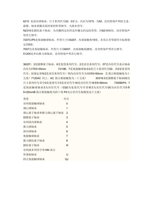
6210 是深沟球轴承,尺寸系列代号02,0省去,内径为10*5,为50,没有特别声明防尘盖、游隙、轴承套圈及保持架材料等细节,为基本型号。
N2315是圆柱滚子轴承,为内圈两边有挡边外圈无挡边的类型,同6210相同,没有特别声明其它细节。
7207C/P5是角接触球轴承,外型尺寸同6207,内部接触角15度,各项公差等级符合标准规定的5级。
7007也是角接触轴承,外型尺寸同6007,内部接触角25度,没有特别声明其它细节。
51205是单向推力球轴承,没有特别声明其它细节。
36207:3是圆锥滚子轴承,6是宽度系列代号,2是直径系列代号,07是内径代号表示轴承内径为7乘5=35mm 7210B:7是角接触球轴承2是尺寸系列代号02,其0宽度系列代号,按规定省略2是直径系列代号!10为内径代号为10乘5=50mm C指公称接触角为十五度!7120AC同上,AC指公称接触角为二十五度!30316:3是圆锥滚子轴承03为尺寸系列代号其中0是宽度代号3是直径代号16是内径代号16乘5=80mm 7305B/P4:7是角接触球轴承3为内径代号(03)0为宽度代号可省略3为直径代号05为内径代号5乘5=25mmB指公称接触角为四十度P4为公差代号指精度高于五级!
类型代号
双列角接触球轴承0
调心球轴承 1
调心滚子轴承和推力调心滚子轴承 2
圆锥滚子轴承 3
双列深沟球轴承 4
推力球轴承 5
深沟球轴承 6
角接触球轴承7
推力圆柱滚子轴承8
圆柱滚子轴承N
双列或多列用字母NN表示
外球面轴承U
四点角接触球轴承QJ。
GC7120A电池充电及电量显示IC
GC7120A电池充电及电量显示IC#概述GC7120A是本公司设计的一款专门用于电池充电控制和电量显示的集成电路。
芯片内含基准电源、负电压发生器、电量测量单元、十段位LCD模拟条显示驱动电路及EL背光照明控制电路。
由于已集成了所有应用部件,因此,GC7120A单片电路就可完成完整的电池充电、电量测量和显示的全部功能。
可用来构成电池充电器、电池电量显示器以及信号强度显示器等。
#特点◆ 内含低功耗晶体振荡器◆ 3V充电池的充电控制和过程显示◆ 过充电、过放电保护控制和报警指示◆ 可设定的10段位LCD模拟条电量显示◆ 内部基准源◆ EL背光显示控制◆ 低功耗:Icc<20uA(电池电量显示模式)#GC7120A工作原理¾电池充电控制及电量显示GC7120A电池充电应用电路图参见图1。
芯片通过连在OSCIN 和OSCOUT两端晶体自建内部时钟,提供液晶驱动电荷泵所必须的时钟。
电荷泵建立负压后,内部基准也得以建立。
通过连在VDD和OPTR两端的电阻RREF可微调基准电压。
有了基准电压作参考,内部测量电路可对待充电的电池电量进行测量。
如测量的结果显示电池电量低于设定的满度值,则芯片通过LEDLOW端口给出电池欠电压指示,并从CONT端口发出充电控制信号开始充电,充电过程中,LCD模拟条会动态刷新显示,以表示处于充电过程,直至电池电量达到已设定的满度值。
一待电池充到满度值,芯片从LED端发出电池充满指示,并从CONT端撤消充电信号,切断充电回路,并显示稳定的电池电压。
待充电电池的欠电压指示值可由RCV端口到VDD的电阻RRCV的阻值来调整(最低-1.6V)。
待充电电池的电压满度值可由输入VIN的电压比值决定,用户可通过比例电阻R4、R5自行确定。
¾电池电量测量电路工作原理电池电量测量电路的基本工作原理大致和充电电路相同,但芯片工作电源由电池供电(1.3V~3.6V),参见图2。
这时芯片中CONT、LEDLOW 和LEDOVER可不连接。
X20(c)AO4622 13位数字转换模块说明书
X20(c)AO46221 General informationThe module is equipped with 4 outputs with 13-bit (including sign) digital converter resolution. It is possible to select between the current and voltage signal using different terminals.•4 analog outputs•Either current or voltage signal possible•13-bit digital converter resolution2 Coated modulesCoated modules are X20 modules with a protective coating for the electronics component. This coating protects X20c modules from condensation and corrosive gases.The modules' electronics are fully compatible with the corresponding X20 modules.For simplification purposes, only images and module IDs of uncoated modules are used in this data sheet.The coating has been certified according to the following standards:•Condensation: BMW GS 95011-4, 2x 1 cycle•Corrosive gas: EN 60068-2-60, method 4, exposure 21 days2.1 Starting temperatureThe starting temperature describes the minimum permissible ambient temperature when the power is switched off at the time the coated module is switched on. This is permitted to be as low as -40°C. During operation, the conditions as specified in the technical data continue to apply.Information:It is important to absolutely ensure that there is no forced cooling by air currents in a closed control cabinet, for example using a fan or ventilation slots.3 Order dataTable 1: X20AO4622, X20cAO4622 - Order data4 Technical dataTable 2: X20AO4622, X20cAO4622 - Technical dataTable 2: X20AO4622, X20cAO4622 - Technical data1) 4 to 20 mA: From upgrade version 1.0.2.0 and hardware revision "I0"2)Based on the current output value.3)Based on the entire output range.4)Based on the output range.5 LED status indicatorsFor a description of the various operating modes, see section "Additional information - Diagnostic LEDs" of the X20 system user's manual.1)Depending on the configuration, a firmware update can take up to several minutes.The individual channels can be configured for either current or voltage signals. The type of signal is also determined by the terminals used.1X 20 A O 4622234r e 7 Connection exampleAO8 Output circuit diagramTo ensure proper operation, the following points must be taken into account:•The derating values listed below must be taken into account.•In mixed operation with one current output, the mean value of both derating curves must be applied.•In mixed operation with 2 or 3 current outputs, the derating of the current outputs must be applied.10 Register description10.1 General data pointsIn addition to the registers described in the register description, the module has additional general data points. These are not module-specific but contain general information such as serial number and hardware variant. General data points are described in section "Additional information - General data points" of the X20 system user's manual.10.2 Function model 0 - Standardand function model 1 - I/O with fast response10.3 Function model 254 - Bus controller1)The offset specifies the position of the register within the CAN object.10.3.1 Using the module on the bus controllerFunction model 254 "Bus controller" is used by default only by non-configurable bus controllers. All other bus controllers can use other registers and functions depending on the fieldbus used.For detailed information, see section "Additional information - Using I/O modules on the bus controller" of the X20 user's manual (version 3.50 or later).10.3.2 CAN I/O bus controllerThe module occupies 1 analog logical slot on CAN I/O.10.4 Function model comparisonFunction model 0: I/O without jitter (standard)With a minimum cycle of ≥400 μs, the corrected values are output in the next cycle. This reduces jitter to a minimum. Function model 1: I/O with fast responseWith a minimum cycle of ≥400 μs, the corrected values are output in the same cycle (optimized response).The two function models compared10.5 Analog outputsThe individual channels can be configured for either current or voltage signals. The type of signal is also determined by the terminals used.10.5.1 Output values of the analog outputName:AnalogOutput01 to AnalogOutput04The normalized output values are specified via these registers. After a permissible value is transferred, the module outputs the corresponding current or voltage.1)Starting with upgrade version 1.0.2.0 and hardware revision "I0"10.5.2 Setting the channel typeName:ConfigOutput01The channel type of the outputs can be defined in this register.The individual channels are designed for current and voltage signals. The differentiation is made by different ter-minal connections; because of different adjustment values for current and voltage, the output signal must also be selected. The following output signals can be set:•±10 V voltage signal•0 to 20 mA current signal•Bit structure:10.6 Minimum cycle timeThe minimum cycle time specifies the time up to which the bus cycle can be reduced without communication errors occurring. It is important to note that very fast cycles reduce the idle time available for handling monitoring, diagnostics and acyclic commands.10.7 Minimum I/O update timeThe minimum I/O update time specifies how far the bus cycle can be reduced so that an I/O update is performed in each cycle.。
轴承代号的含义
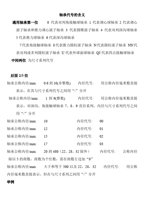
轴承代号的含义通用轴承第一位0 代表双列角接触球轴承1代表调心球轴承2代表调心滚子轴承和推力调心滚子轴承3代表圆锥滚子轴承4代表双列深沟球轴承5代表推力球轴承6代表深沟球轴承7代表角接触球轴承8代表推力圆柱滚子轴承N代表圆柱滚子轴承NN代表双列或多列圆柱滚子轴承U代表外球面球轴承QJ代表四点接触球轴承中间两位为尺寸系列代号后面2/3位轴承公称内径/mm: 0.6到10(非整数) 内径代号: 用公称内径毫米数直接表示,在其与尺寸系列代号之间用“/”分开轴承公称内径/mm: 1到9(整数) 内径代号: 用公称内径毫米数直接表示,对深沟、角接触球轴承7、8、9直径系列,内径与尺寸系列代号之间用“/”分开轴承公称内径/mm: 10 内径代号: 00轴承公称内径/mm: 12 内径代号: 01轴承公称内径/mm: 15 内径代号: 02轴承公称内径/mm: 17 内径代号: 03轴承公称内径/mm: 20到480(22,28,32除外)内径代号: 公称内径除以5的商数,商数为个位数,需在商数左边加“0”轴承公称内径/mm: 大于和等于500以及22,28,32 内径代号: 用公称内径毫米数直接表示,但在与尺寸系列之间用“/”分开举例36207:3是圆锥滚子轴承,6是宽度系列代号,2是直径系列代号,07是内径代号表示轴承内径为7乘5=35mm7210B:7是角接触球轴承2是尺寸系列代号02,其0宽度系列代号,按规定省略2是直径系列代号!10为内径代号为10乘5=50mm C指公称接触角为十五度!7120AC同上,AC指公称接触角为二十五度!30316:3是圆锥滚子轴承03为尺寸系列代号其中0是宽度代号3是直径代号16是内径代号16乘5=80mm7305B/P4:7是角接触球轴承3为内径代号(03)0为宽度代号可省略3为直径代号05为内径代号5乘5=25mmB指公称接触角为四十度P4为公差代号指精度高于五级!。
莫萨 UC-7120 系列肢体型 palm-sized 工业计算机说明书
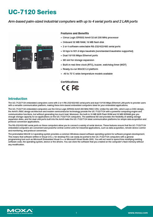
UC-7120SeriesArm-based palm-sized industrial computers with up to4serial ports and2LAN portsFeatures and Benefits•Cirrus Logic EP9302Arm932-bit200MHz processor•Onboard32MB RAM,16MB flash disk•2or4software-selectable RS-232/422/485serial ports•50bps to921.6kbps baudrate(nonstandard baudrates supported)•Dual10/100Mbps Ethernet ports•SD slot for storage expansion•Built-in real-time clock(RTC),buzzer,watchdog timer(WDT)•Ready-to-run WinCE5.0platform•-40to75°C wide-temperature models availableCertificationsIntroductionThe UC-7122/7124embedded computers come with2or4RS-232/422/485serial ports and dual10/100Mbps Ethernet LAN ports to provide users with a versatile communication platform,making these Arm-based embedded computers ideal for your embedded applications.The UC-7122/7124embedded computers use the Cirrus Logic EP9302Arm9200MHz RISC CPU.Unlike the x86CPU,which uses a CISC design, the Arm9’s RISC design architecture and modern semiconductor technology provide the UC-7122/7124with a powerful computing engine and communication functions,but without generating too much heat.Moreover,the built-in16MB NOR Flash ROM and32MB SDRAM give you enough storage capacity to run applications on the UC-7122/7124computers.The additional SD slot provides the flexibility of adding storage expansion disks,and the dual LAN ports built into the Arm9make the UC-7122/7124ideal communication platforms for simple data acquisition and protocol conversion applications.The RS-232/422/485serial ports on these computers allow you to connect a variety of serial devices.These features ensure that the UC-7122/7124 embedded computers are convenient and powerful central control units for industrial applications,such as data acquisition,remote device control and monitoring,and protocol conversion.The preinstalled WinCE5.0operating system provides a common Windows-based software operating system for software program development. This means that software written in Visual C/C++for desktop PCs can easily be ported to the UC-7122/7124computers with a general programming tool such as Microsoft Embedded Visual C++or Microsoft Visual Studio2005.You will not need to spend time modifying existing software code,the operating system,device or the drivers.You can store the software that you created on the computer’s flash memory without any modification.AppearanceUC-7122UC-7124SpecificationsComputerCPU Cirrus EP9302Arm9,200MHzSupported OS Windows Embedded Compact5.0Storage Slot SD slots x1Computer InterfaceEthernet Ports Auto-sensing10/100Mbps ports(RJ45connector)x2Serial Ports UC-7122Series:RS-232/422/485ports x2,software-selectable(DB9male)UC-7124:RS-232/422/485ports x4,software-selectable(RJ45)USB2.0USB2.0hosts x1,type-A connectorsConsole Port RS-232(TxD,RxD,GND),4-pin header output(115200,n,8,1)MemoryFlash16MBSDRAM32MBEthernet Interface10/100BaseT(X)Ports(RJ45connector)2Magnetic Isolation Protection 1.5kV(built-in)USB InterfaceStorage Port USB Type AUSB Standards USB1.1/2.0compliantLED IndicatorsSystem System Ready x1SD slots x1LAN2per port(10/100/1000Mbps)Serial2per port(Tx,Rx)Serial InterfaceBaudrate50bps to921.6kbps(supports non-standard baudrates)Connector UC-7122Series:DB9maleUC-7124Series:RJ45Data Bits5,6,7,8Flow Control RTS/CTS,XON/XOFF,ADDC®(automatic data direction control)for RS-485,RTSToggle(RS-232only)ESD Protection4kV,for all signalsNo.of Ports UC-7122Series:2UC-7124Series:4Parity None,Even,Odd,Space,MarkRS-485Data Direction Control ADDC®(automatic data direction control)Serial Standards RS-232/422/485Stop Bits1,1.5,2Serial SignalsRS-232TxD,RxD,RTS,CTS,DTR,DSR,DCD,GNDRS-422Tx+,Tx-,Rx+,Rx-,GNDRS-485-2w Data+,Data-,GNDRS-485-4w Tx+,Tx-,Rx+,Rx-,GNDPower ParametersConnection Removable terminal blockInput Current UC-7122Series:170mA@24VDC,340mA@12VDCUC-7124Series:180mA@24VDC,360mA@12VDCInput Voltage12to48VDCNo.of Power Inputs1Operating Voltage12to48VDCPower Connector3-pin terminal blockTerminal block(for DC models)Power Consumption UC-7122Series:4.1W(max.)UC-7124Series:4.3W(max.)Physical CharacteristicsHousing MetalDimensions(with ears)100x111x26mm(4.18x4.37x1.02in)Dimensions(without ears)77x111x26mm(3.03x4.37x1.02in)Weight UC-7122Series:190g(0.42lb)UC-7124Series:200g(0.44lb)Installation DIN-rail mounting(with optional kit),Wall mounting(standard) Environmental LimitsOperating Temperature Standard Models:-10to60°C(14to140°F)Wide Temp.Models:-40to75°C(-40to167°F)Storage Temperature(package included)Standard Models:-20to80°C(-4to176°F)Wide Temp.Models:-40to85°C(-40to185°F)Ambient Relative Humidity5to95%(non-condensing)Standards and CertificationsEMC EN55032/24,EN61000-6-2/-6-4,EN61000-3-2Class A,EN61000-3-3 EMI CISPR32,FCC Part15B Class AEMS IEC61000-4-11DIPsIEC61000-4-2ESD:Contact:4kV;Air:8kVIEC61000-4-3RS:80MHz to1GHz:3V/mIEC61000-4-4EFT:Power:1kV;Signal:0.5kVIEC61000-4-5Surge:Power:1kVIEC61000-4-6CS:150kHz to80MHz:10V/m;Signal:10V/mIEC61000-4-8PFMFSafety EN60950-1,IEC60950-1,UL60950-1Vibration IEC60068-2-6DeclarationGreen Product RoHS,CRoHS,WEEEMTBFTime UC-7122Series:234,746hrsUC-7124Series:210,233hrsStandards Telcordia(Bellcore),GBWarrantyWarranty Period5yearsDetails See /warrantyPackage ContentsDevice1x UC-7120Series computerCable1x4-pin header to DB9console port1x DB9male to RJ458-pin1x Ethernet,crossover1x terminal block to power jack converterPower Supply1x power adapter,universalDocumentation1x document and software CD1x product certificates of quality inspection,Simplified Chinese1x product notice,Simplified Chinese1x quick installation guide1x warranty cardDimensionsUC-7122UC-7124Ordering InformationModel Name Serial Ports LAN Ports USB2.0Storage Slots OS Operating Temp. UC-7122-CE221SD Card WinCE5.0-10to60°C UC-7124-CE421SD Card WinCE5.0-10to60°C UC-7122-T-CE221SD Card WinCE5.0-40to75°C UC-7124-T-CE421SD Card WinCE5.0-40to75°C Accessories(sold separately)DIN-Rail Mounting KitsDK35A DIN-rail mounting kit,35mm©Moxa Inc.All rights reserved.Updated Nov12,2018.This document and any portion thereof may not be reproduced or used in any manner whatsoever without the express written permission of Moxa Inc.Product specifications subject to change without notice.Visit our website for the most up-to-date product information.。
CH9721P+ CH9722P CH9723P+ CH9733P+ 快充自动测试仪 使用说明书

使用说明书OPERATION MANUALCH9721P+/CH9722P/CH9723P+/CH9733P+快充自动测试仪常州市贝奇电子科技有限公司BEICH ELECTRONIC TECHNOLOGY CO.,LTD.公司声明注意事项:本说明书版权归常州市贝奇电子科技有限公司所有,贝奇电子保留所有权利。
未经贝奇电子书面同意,不得对本说明书的任何部分进行影印、复制或转译。
本说明书适用于CH9721P+快充PD 自动测试仪本说明书适用于CH9722P 快充PD 自动测试仪本说明书适用于CH9723P+快充PD 自动测试仪本说明书适用于CH9723P+快充PD 自动测试仪本说明书包含的信息可能随时修改,恕不另行通知。
最新的说明书电子文档可以从贝奇电子官方网站下载:2017年8月……………………………………..第一版2017年11月…………………………………..第二版2018年10月…………………………………..第三版2019年5月……………………………………..第四版2020年10月……………………………………第五版2021年1月……………………………………..第六版2021年10月…………………………………..第七版本说明书所描述的可能并非仪器所有内容,贝奇电子有权对本产品的性能、功能、内部结构、外观、附件、包装物等进行改进和提高而不作另行说明!由此引起的说明书与仪器不一致的困惑,可与我公司联系。
安全警告:在使用操作和维护本仪器的任何过程中,务必遵守各项安全防护措施。
如果忽视和不遵守这些安全措施及本手册中的警告,不但会影响仪器性能,更可能导致仪器的直接损坏,并可能危及人身安全。
对于不遵守这些安全防范措施而造成的后果,贝奇电子科技有限公司不承担任何后果。
触电危险操作,测试与与仪器维护时谨防触电,非专业人员请勿擅自打开机箱,专业人员如需更换保险丝或进行其它维护,务必先拔去电源插头,并在有人员陪同情况下进行。
1万多个电视机高压包脚位通法
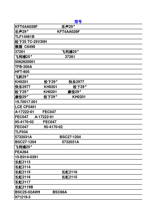
F 1837CE Y261504 松下21″ Y261504 松下21″ F 1837CE 松下21″ F 1837CE Y261504 F1787CE Y261504 松下21″ DNF FN0505 HCF-36631 E105192 E105192 HCF-36631 TFB-4039AD 东芝219 东芝219 TFB-4039AD FD 55 三洋7922 三洋7922 FD 55 TLF70235A JT/128 1242 0068 1242 0068 JT/128 BSC27-01AW2 海燕2132 牡丹64C6 海燕2132 BSC27-01AW2 牡丹64C6 牡丹64C6 BSC27-01AW2 海燕2132 BSC27-01AW1 牡丹64C1A 牡丹64C3 牡丹64C1A BSC27-01AW1 牡丹64C3 牡丹64C3 BSC27-01AW1 牡丹64C1A MSHIFFA04 MSUIFDQ504 334P14-108 三棱27C894 三棱27C-AT1 334P17103 三棱27C894 三棱27C-AT1 三棱27C-AT1 334P17103 334P14-108 三棱27C894 334P17103 334P14-108 334P12902 334P12903 三棱25″ 三棱25″ MITSUBISHIK 25C-SS1 334P12903 三棱25″ MITSUBISHIK 25C794 334P12903 F 1130 三洋6920 20″ 三洋6920 20″ F 1130 F 1117 三洋4505 16″ 三洋4505 16″ F 1117(B) F1117(B) 三洋450516″ BSC23-0101 金利浦14″
金利浦14″ BSC23-0101 FCM-2012E21A 37M2012E-21A BSC21-3366 孔雀14″ BSC23-3366 孔雀14″ BSC21-3366 BSC23-3366 BSC23-3366 优纳拉斯14″ 孔雀14″ TFB-3035B 康艺8135 康艺4507 康艺4507 TFB-3035B 康艺8135 康艺8135 TFB-3035B BSC24-1051P 熊猫2118 2119 2128 熊猫54P36 熊猫2118 2119 2128 熊猫54P36 BSC24-1051P BSC22-2501B 康艺CE3703 凯歌4C370S 康艺CE3703 BSC22-2501B 凯歌4C370S 凯歌4C370S BSC22-2501B 康艺CE3703 TLF15550B DNF.FL2732A 2027017-001 53X0528-001 53X0528-001 2027017-001 假松下TC-2198 730-302-1548 39L7014AI 79A316-2 TLF70100 TLF70100 79A316-2 ATK1061 三棱40″ 三棱40″ ATK1061 BSC25-2951C 金星C542 金星C542 BSC25-2951C BSC26-N0401 TFB 4095BD 金星C6428 TFB 4095BD BSC26-N0401 金星C6428 金星C6428 BSC26-N0401 TFB 4095BD 2435011A 日立CM2110 日立CM2110 2435011A TFB 4131AD 东芝2550 东芝2550 TFB 4131AD KW03027F 3531A TLF15521B TLF15521F TLF15521F TLF15521B BSC25-6503 TD96DPGL4
APW7120AKE-TRG资料
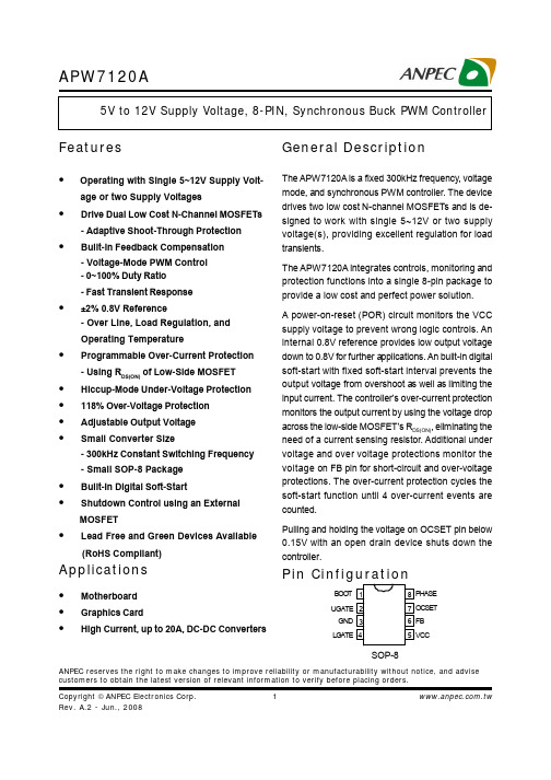
-5 ~ VBOOT+0.3 -0.3 ~ VBOOT+0.3 -5 ~ VCC+0.3 -0.3 ~ VCC+0.3 -10 ~ 30 -3 ~ 16 -0.3 ~ 7 150 -65 ~ 150 260VV源自VoC C
o o
C
Note 1: Absolute Maximum Ratings are those values beyond which the life of a device may be impaired. Exposure to absolute maximum rating conditions for extended periods may affect device reliability.
元器件交易网
APW7120A
Ordering and Marking Information
APW7120A Package Code K : SOP-8 Operating Ambient Temperature Range E : -20 to 70 °C Assembly Material Handling Code Handling Code TR : Tape & Reel Temperature Range Assembly Material Package Code L : Lead Free Device G : Halogen and Lead Free Device APW7120A XXXXX XXXXX - Date Code
Unless otherswise specified, these specifications apply over VCC = 12V, VBOOT = 12V and TA = -20 ~ 70oC. Typical values are at TA = 25oC.
WFM7120技术资料

视频监视 - 3G(3 Gb/s) - DL(双链路) - HD(高清晰度 SDI) - SD(标准清晰度 SDI) - CPS(复合模拟)
音频监视 - AD(AES、嵌入音频和模拟音频) - DDE(杜比数字和杜比 E 音频)
测量和分析 - JIT(3 Gb/s 抖动测量) - EYE、PHY(物理层分析) - DAT(数据分析) - SIM(同时输入监视) - AVD(A/V 延时测量)
WFM7020
WFM7020 为模拟、数字、高帧频数字视频和多种音频格式的 基本监视提供了一种理想的解决方案。
CaptureVu 现已成为 WFM7120 和 WFM6120 的标准配置,它 能够捕获一视频帧的数据并重建该数据信号的任意波形迹线显 示,以便对其数字结构进行分析。利用 USB 端口或通过以太网 端口可以传送已捕获的视频数据。
在附属数据状态显示中,可以解码辅助数据,例如Active Format Description(有效格式描述符,AFD)、视频索引、宽高比、WSS 以及 ARIB 信息等。
Aux 数据状态显示提供了各种元数据例如隐蔽字幕 CEA608 或 CEA708、广播标志 /CGMS、图文电视、ARIB、时间码、AFD (有效格式描述符)、视频索引宽高比以及宽屏信令等的概要信 息。
现在有了各种元数据,它们提供了整个信号处理链路中的各种 设备的信息,监视这种元数据是十分重要的,可以确保这些设 备能够正确地处理信号。例如,格式正确的 AFD 确保显示器有 正确的宽高比和自动的刻度显示,这样在波形监视器的图像显 示中,含有二进制的数据和文本说明才是可用的。
Eaton 197212 产品说明书
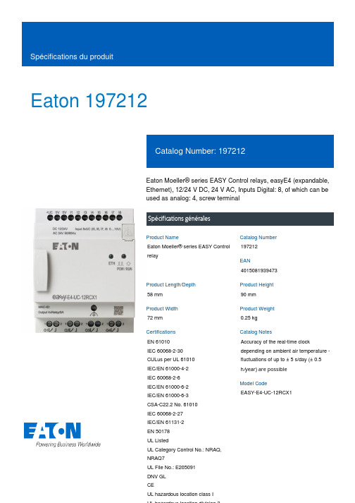
Eaton 197212Eaton Moeller® series EASY Control relays, easyE4 (expandable, Ethernet), 12/24 V DC, 24 V AC, Inputs Digital: 8, of which can be used as analog: 4, screw terminalSpécifications généralesEaton Moeller® series EASY Control relay197212401508193947358 mm 90 mm 72 mm 0.25 kg EN 61010 IEC 60068-2-30 CULus per UL 61010 IEC/EN 61000-4-2 IEC 60068-2-6 IEC/EN 61000-6-2 IEC/EN 61000-6-3 CSA-C22.2 No. 61010 IEC 60068-2-27 IEC/EN 61131-2 EN 50178 UL ListedUL Category Control No.: NRAQ, NRAQ7UL File No.: E205091 DNV GL CEUL hazardous location class IAccuracy of the real-time clock depending on ambient air temperature - fluctuations of up to ± 5 s/day (± 0.5 h ⁄year) are possibleEASY-E4-UC-12RCX1Product NameCatalog Number EANProduct Length/Depth Product Height Product Width Product Weight Certifications Catalog NotesModel CodeExpandableNetworkable (Ethernet)TimerRelay outputReal time clockLCD-display used as status indication of Digital inputs 12 V DC LCD-display used as status indication of Digital inputs 24 V DC IP20Pulse shape: Square (digital inputs 24 V DC)Cable length: ≤ 20 m (screened, Digital inputs 24 V DC)Number: 4 (I1, I2, I3, I4 - Digital inputs 24 V DC)Pulse pause ratio: 1:1 (Digital inputs 24 V DC)Counter frequency: 5 kHz (Digital inputs 24 V DC)50/60 Hz (Digital inputs, at 24 V DC)According to EN 50178, EN 61010-2-201, UL61010-2-201, CSA-C22.2 NO. 61010-2-20125,000 Operations (Filament bulb load at 500 W, 115/120 V AC) 25,000 Operations (Fluorescent lamp load 10 x 58 W at 230/240 V AC, uncompensated)25,000 Operations (Fluorescent lamp load 10 x 58 W at 230/240 V AC, with upstream electrical device)25,000 Operations (Fluorescent lamp load 1 x 58 W at 230/240 V AC, conventional, compensated)25,000 Operations (Filament bulb load at 1000 W, 230/240 V AC)10,000,000 OperationsFront build in possibleTop-hat rail fixing (according to IEC/EN 60715, 35 mm)Wall mounting/direct mountingRail mounting possibleScrew fixing using fixing brackets ZB4-101-GF1 (accessories)III2Control relays easyE4Features Fitted with: Indication Degree of protection Frequency counterInput frequency Insulation resistance Lifespan, electricalLifespan, mechanical Mounting methodOvervoltage category Pollution degree Product category ProtocolMODBUS TCP/IP6 kV (contact-coil)≤ 5 %EASYSOFT-SWLIC/easySoft70.5 Hz, Inductive load, Relay outputs 2 Hz, Resistive load/lamp load, Relay outputs 10 Hz, Relay outputs easyE4 base device easyE4B 300 Light Pilot Duty, UL/CSA Control Circuit Rating Codes AC R 300 Light Pilot Duty, UL/CSA Control Circuit Rating Codes DC AC/DC50 mm Drop height, Drop to IEC/EN 60068-2-310.3 mHorizontal Vertical15 g, Mechanical, according to IEC/EN 60068-2-27, Half-sinusoidal shock 11 ms, 18 Impacts 57 - 150 Hz, 2 g constant acceleration According to IEC/EN 60068-2-6 10 - 57 Hz, 0.15 mm constant amplitude795 - 1080 hPa (operation)-25 °C 55 °C-40 °C70 °CCondensation: prevent with appropriate measuresClearance in air and creepage distances according to EN 50178, EN 61010-2-201, UL61010-2-201, CSA-C22.2 NO. 61010-2-2015 - 95 % (IEC 60068-2-30, IEC 60068-2-78)Rated impulse withstand voltage (Uimp)Residual ripple ResolutionSoftwareSwitching frequencyTypeUsed with Utilization categoryVoltage type Drop and toppleHeight of fall (IEC/EN 60068-2-32) - max Mounting position Shock resistanceVibration resistanceAir pressureAmbient operating temperature - min Ambient operating temperature - max Ambient storage temperature - min Ambient storage temperature - max Environmental conditionsRelative humidityAir dischargeTerminal capacity1 min (Range H:M)1 s (Range M:S)12 Bit (value 0 - 4095, Analog inputs)5 ms (Range S)8 kV2 kV, Signal cable2 kV, Supply cableAccording to IEC/EN 61000-4-46 kV10 V/m at 0.8 - 1.0 GHz (according to IEC EN 61000-4-3)1 V/m at 2.0 - 2.7 GHz (according to IEC EN 61000-4-3)3 V/m at 1.4 - 2 GHz (according to IEC EN 61000-4-3)10 V (according to IEC/EN 61000-4-6)Class B (EN 61000-6-3)2 kV, Supply cables, asymmetrical, power pulses (Surge), EMC According to IEC/EN 61000-4-5, power pulses (Surge), EMC1 kV, Supply cables, symmetrical, power pulses (Surge), EMC≤ 1 ms from rated voltage (12 V DC)10 ms 0.2 - 2.5 mm² (22 - 12 AWG), flexible with ferrule0.2 - 4 mm² (AWG 22 - 12), solid3.5 x 0.8 mm, Terminal screw0.6 Nm, Screw terminals8 A3 W200000 Operations at DC-13, 24 V DC, 1 A (500 Ops./h) 300000 Operations at AC-15, 250 V AC, 3 A (600 Ops./h)240 V10.2 - 28.8 V DC12 V DC (digital inputs)12/24 V DC (-15 %/+ 20 % - power supply)24 V AC (digital inputs)24 V DC (digital inputs)20.4 - 26.4 V ACMax. 300 V AC24 V AC (-15 %/+10 % - power supply)240 V ACMax. 300 V DC50/60 Hz (± 5%)20.4 VAC26.4 VAC10.2 VDC28.8 VDCBurst impulseContact dischargeElectromagnetic fieldsImmunity to line-conducted interference Radio interference classSurge ratingVoltage dips Screwdriver sizeTightening torqueConventional thermal current ith of auxiliary contacts (1-pole, open)Power consumptionRated breaking capacityRated insulation voltage (Ui)Rated operational voltageSupply frequencySupply voltage at AC, 50 Hz - minSupply voltage at AC, 50 Hz - maxSupply voltage at DC - minSupply voltage at DC - max1 A DC, at R 300 (UL/CSA)5 A AC, max. thermal continuous current cos ϕ = 1 at B 300(UL/CSA)8 A DC, at 24 V DC (UL/CSA)10 A AC, at 240 V AC (UL/CSA)≥ 1A (T), Fuse, Power supplyScrew terminalEthernet: RJ45 plug, 8-pole10/100 MBit/sStatus indication of Power/RUNStatus indication of Ethernet: LED100 m, unscreened, Digital inputs 12 V DC 100 m, unscreened, Digital inputs 24 V AC ≤ 30 m, screened, Analog inputs 100 m, unscreened, Digital inputs 24 V DC 40 m (max. per input), Digital inputs 24 V DCCAT5± 2 s/day, Real-time clock to inputs (± 0.2 h⁄Year)± 2 %, (I7, I8) ± 0.12 V, of actual value, within a single device (Analog Inputs)± 1 %, Repetition accuracy of timing relays (of values)± 3 %, of actual value, two easy devices (Analog Inputs)Each CPU cycle, Analog inputs20 ms typ., Digital inputs 12 V DC (I1 - I8), Delay time from 0 to 1, Debounce ON20 ms typ., Digital inputs 24 V DC (I1 - I8), Delay time from 1 to 0, Debounce ON0.015 ms typ., Digital inputs 12 V DC (I1 - I8), Delay time from 0 to 1, Debounce OFF0.015 ms typ., Digital inputs 24 V DC (I1 - I8), Delay time from 1 to 0, Debounce OFF0.015 ms typ., Digital inputs 24 V DC (I1 - I8), Delay time from 0 to 1, Debounce OFF0.015 ms typ., Digital inputs 12 V DC (I1 - I8), Delay time from 1 to 0, Debounce OFF20 ms typ., Digital inputs 12 V DC (I1 - I8), Delay time from 1 to 0, Debounce ON20 ms typ., Digital inputs 24 V DC (I1 - I8), Delay time from 0 to 1, Debounce ONUninterrupted currentShort-circuit protectionConnection typeData transfer rateLED indicatorCable length Cable type AccuracyConversions Delay timeNumber of counter inputs: 2 (I1 + I2, I3 + I4) Signal offset: 90°Pulse pause ratio: 1:1Value range: -2147483648 to +2147483647Pulse shape: SquareCounter frequency: ≤ 5 kHzCable length: ≤ 20 m (screened)Voltage (DC)2.2 mA (I5 - I8, at 24 V DC, at signal 1)3.3 mA (I1 - I4, at 24 V DC, at signal 1)1 mA (Analog inputs)200 mA13.3 kΩStatus 1: ≥ 15 V DC (I1 - I4, Digital inputs, 24 V DC)Status 0: ≤ 8 V DC (I5 - I8, Digital inputs, 24 V DC)At signal 0: ≤ 5 V (I1 - I8, sinusoidal, Digital inputs, 24 V DC)At signal 1: ≥ 15 V (I1 - I8, sinusoidal, Digital inputs, 24 V DC)Status 1: ≥ 8 V DC (I5 - I8, Digital inputs, 24 V DC)Signal 0: ≤ 5 V DC (I1 - I4, Digital inputs, 12 V DC)Status 0: ≤ 15 V DC (I1 - I4, Digital inputs, 24 V DC)3600/360 VA (AC, at B 300)28/28 VA (DC, at R 300)448NoneBetween Digital inputs 24 V AC and Outputs: yesBetween Relay outputs and expansion devices: yesBetween Digital inputs 12 V DC and expansion devices: yes Between Relay outputs: yesBetween Analog inputs and Outputs: yesBasic isolation: 600 V AC (Relay outputs)Between Analog inputs and expansion devices: yesBetween Digital inputs 24 V AC and expansion devices: yes Between Relay outputs and Power supply: yesBetween Digital inputs 24 V DC and Outputs: yesBetween Analog inputs and Ethernet: yesSafe isolation according to EN 50178: 300 V AC (Relay outputs) Between Digital inputs 24 V AC and Ethernet: yesBetween Digital inputs 24 V DC and expansion devices: yes Between Relay outputs and Inputs: yesBetween Digital inputs 12 V DC and Ethernet: yesBetween Digital inputs 12 V DC and Outputs: yesBetween Digital inputs 24 V DC and Ethernet: yesYes, for supply voltage (Siemens MPI optional)None300 V AC, Between coil and contact, According to EN 50178 300 V AC, Between two contacts, According to EN 501784 W0 W0 W0 AIncremental counterIncremental encoder InputInput currentInput impedanceInput voltageMaking/breaking capacity Number of inputs (analog) Number of inputs (digital)Explosion safety category for gasPotential isolationProtection against polarity reversalExplosion safety category for dustSafe isolationEquipment heat dissipation, current-dependent PvidHeat dissipation capacity PdissHeat dissipation per pole, current-dependent PvidRated operational current for specified heat dissipation (In) Static heat dissipation, non-current-dependent Pvs4Relay outputs in groups of 1> 500 mA (Relay outputs, Recommended for load: 12 V AC/DC) 4 Relay OutputsVoltageCurrentNot permitted-2147483648 - 2147483647 (value range)Number: 4 (I1, I2, I3, I4 - Digital inputs 24 V DC)≤ 20 m (cable length, screened)1:1 (Pulse pause ratio)Square (pulse shape)10 kHz, Counter frequency0 - 10 V DC, Analog inputs 3 WMeets the product standard's requirements.Meets the product standard's requirements.Meets the product standard's requirements.Meets the product standard's requirements.Meets the product standard's requirements.Does not apply, since the entire switchgear needs to be evaluated.Does not apply, since the entire switchgear needs to be evaluated.Meets the product standard's requirements.Meets the product standard's requirements.Meets the product standard's requirements.Does not apply, since the entire switchgear needs to be evaluated.Does not apply, since the entire switchgear needs to be evaluated.Is the panel builder's responsibility.Is the panel builder's responsibility.Is the panel builder's responsibility.Is the panel builder's responsibility.Number of outputs (analog)Number of outputs (digital) OutputParallel switchingRapid counter inputs Signal range 10.2.2 Corrosion resistance10.2.3.1 Verification of thermal stability of enclosures10.2.3.2 Verification of resistance of insulating materials to normal heat10.2.3.3 Resist. of insul. mat. to abnormal heat/fire by internal elect. effects10.2.4 Resistance to ultra-violet (UV) radiation10.2.5 Lifting10.2.6 Mechanical impact10.2.7 Inscriptions10.3 Degree of protection of assemblies10.4 Clearances and creepage distances10.5 Protection against electric shock10.6 Incorporation of switching devices and components10.7 Internal electrical circuits and connections10.8 Connections for external conductors10.9.2 Power-frequency electric strength10.9.3 Impulse withstand voltageEaton Corporation plc Eaton House30 Pembroke Road Dublin 4, Ireland © 2023 Eaton. Tous droits réservés.Eaton is a registered trademark.All other trademarks are property of their respective owners./socialmediaIs the panel builder's responsibility.The panel builder is responsible for the temperature rise calculation. Eaton will provide heat dissipation data for the devices.Is the panel builder's responsibility.Is the panel builder's responsibility.The device meets the requirements, provided the information in the instruction leaflet (IL) is observed.eaton-electrical-timers-easy-control-relays-characteristic-curve-002.eps DA-DC-00004708.pdf DA-DC-00004703.pdf MZ049014EN mz049001en.pdf DA-MN-h1430de MN050009_FR Video easy E4 control relay IL050020ZU DA-CS-uc_12rcx1DA-CD-uc_12rcx12723DIM-100eaton-logic-relays-easy-control-relays-dimensions.eps eaton-general-easy-control-relays-symbol-002.tifeaton-modular-plc-easy-control-relays-3d-drawing-002.eps10.9.4 Testing of enclosures made of insulating material 10.10 Temperature rise10.11 Short-circuit rating10.12 Electromagnetic compatibility 10.13 Mechanical functionCharacteristic curveDeclarations of conformity Guide utilisateurInstallation videos Instructions d'installation mCAD model Schémas。
电视机教案
课题一电源电路安装与调试实习要点及训练目标:该课题的实习可以分为安装,调试和维修三大步骤.安装与调试目的是为了进一步熟悉电路原理和实物与符号的对应取得电路正常工作时的各种数据,便于今后维修时参考,进一步提高维修水平.通过以上三个阶段实习应达到以下几个训练目标:1、能熟练分析电路工作原理,打开电视机后盖,应能立即指出电源电路的准确位置,说明它在电路中的作用,规格,型号及主要质量要求.2.能用万用表准确检测元器件的质量.3.能够独立检测关键点的数据,并进行常见故障的维修.4.通过实践掌握维修中常见的几种检测方法:(1)在路电阻法.(2)关键点电路检测法(3)线路分割法(4)在路电压法.复习与提问1.常见的稳压电源种类,稳压电源的组成部分,请学生画出稳压电源方框图.2.常见的整流电路的类型,电路图.3.实习机电路工作原理.(略)4.主要元器件的作用.5.主要元器件的参数要求.以上内容均在串联稳压电源的安装课题中讲授过,一、元器件的检测:1.电源变压器用万用表测其初、次级阻值。
2.晶体二极管的检测(图示仪)(1).最大正向导通电流要求Irm≥1A.(2).最大反向击穿电压要求Vrm≥50V.(3).稳压二极管的稳压值要求7.5v ~ 8v.3.晶体三极管的检测.二.电源电路的安装与调试.1.准备:毫伏表 1台调压器 1台万用表 1块电烙铁 1把起子 1把假负载1只2.技术要求:<1>输出电压在12v上,下可调.当市电为220v时,直流输出电压应为12v±0.2v.<2>纹波电压:当交流电220v时.10Ω假负载电阻上纹波电压≤5mV.<3>交流消耗:满载时≤150mA,空载时≤40mA3.调试前准备:<1>.测量静态电阻值:a.接通电源开关,测量电源插头两端电阻,若阻值正常,说明变压器初级与电源开关、保险丝接触良好,接线正确.b.测量调整管c、e两端,b、c两端阻值.若阻值正常,则说明无短路现象.c.测量电源输出端对地电阻,若阻值正常,则无输出对地短路现象.以上三条,其中一条出现异常,切不能通电.<2>仪器与电路的连接:4.调试步骤与方法:<1>测电源消耗和负载特性:将调压器调准在220v,把10Ω假负载接上,调整W1,直流输出电压为12v±0.2v,此时交流电流表指示应≤150mA,当断开10Ω假负载时,空载时应≤40mA.<2>测电压调整率:直流电源输出端接上10Ω假负载,调压器从180v 调到240v,直流电压输出应在12±0.2v.<3>测纹波电压:毫伏表接10Ω负载两端,将表置10mV档,检查表上纹波电压应≤5mV.电源检测与调试记录如下:示范指导:一.元器件检测:1.变压器质量判断.2.主要元器件的质量检测.3.晶体管二、三极管参数测试.二.电路的安装与调试:1.元器件的安装,焊接.重点电源调整管.2.调试步骤.三.一般常见故障的查找:1.在路电阻发2.关键点电流检测法3.线路分割法4.在路电压法巡回指导:一、线路安装:1.检查二极管,三极管,电解电容的极性,型号插孔位置不能插错.2.变压器初、次极要分清,巡回检查应注意.3.大功率调整管的安装.二、调试过程中可能出现的问题:<一>.空载时输出电压调不下来.空载时输出电压一直偏高,但接上负载后电压可调至11.5v,而且较稳定,原因有下:<1>.调整管Iceo过大,应更换.<2>.激励管Iceo过大,应更换.<3>.取样放大管导通不够,更换大ß的管子.若经验明,电源在空载时输出电压偏高,满载时电压正常,并上、下可调,可投入使用.<二>.接上假负载后调整管发烫.电压能上、下可调,可将调压管分流电阻接上再调,若情况好转,说明投入使用后不会又问题.<三>.调不到12v附近.出现这种情况有可能元器件安装不对,或个别元器件损坏.<1>.保护管损坏.<2>.取样放大管损坏.<3>.基准电压不正确或稳压管接反.<4>.调整管、激励管损坏.以上管子可采用在线电阻法判断好坏.安全注意事项1.变压器主、次级应分清,焊接时应套上绝缘套,避免人手触摸后触电.2.交流电源火线必须经开关,也必须上绝缘套.3.焊接完毕,必须经”自查”,互查”方可通电,禁止私自通电.4.在做假负载实验时,使用交流调压器时,应注意主、次级,避免接错,损坏调压器,在拆除调压器时,应先关闭电源.5.焊接完毕,应及时拔下电烙铁插头,放学,下课前应提醒,检查. 评分标准:课后小结:课题二高频头的安装与检测实习要点及训练目标:1.熟悉黑白电视机中常见的机械调协式VHF高频头和UHF高频头的基本结构,正确组装和使用.在必要时,能拆装某些部件,进行直观检查.2.能用万用表检测各晶体管直流工作状态.可判断是否正常工作,会替换已坏的元件.3.会用扫频仪测试高频头主要特性曲线,对曲线是否符合要求作出评价.4.正确安装VHF高频头和UHF高频头以及两高频头之间的电路连接.复习提问:1.扫频仪的作用,使用方法及使用注意事项,幅频特性曲线的测试及增益计算.2.高频头的作用?组成结构?3.图象中频频率,第一伴音频率,伴音第二频率各为多少?入门指导:一、高频头的分类:1.按接收频段分:“V”头,接收1-12频道.“U”头,接收13-68频道.2.按调谐方式分:机械式和电子调谐式.机械调谐式高频头,可根据频道转换方式不同分:并联电感切换式(又称转鼓式),串联电感分段短路式(又称转盘式波段开关).可变电容连续调谐式.黑白机往往用机械式”V”头和”U”头,实现全频道接收.彩电中则常采用U、V 一体式的电子调谐高频头,而且要配合专用的电视节目预选器进行节目的预选和转换.二、高频头的技术要求及装配使用事项:(一).KP12-3的主要技术要求:1).接收频道:1-12频道2).输出中频:图象38MHZ,(1日37MHZ)伴音31.5MHZ,(1日30.5MHZ)3).工作电压:直流11.5V±0.5V.4).AGC特性:起控电压为3±0.25V,控制范围>20dB.5).功率增益≥20dB,各频道增益差<10dB.6).本振微调范围: ±1.5m˜±4.5m.7).输出波形:双峰曲线.即图象中频fpi和伴音中频fsi应位于曲线双峰值-3dB(70%)以上,曲线-6dB(50%)处带宽B<11MHz,顶部不平度ΔA≤1.5dB(二).TJT-2型高频头主要参数技术指标:1.接收频道,13˜56频道;2.输出中频:图像:38MHz伴音31.5MHz3.功率增益: ≥-3dB,各频道增益差≤10dB.4.输入阻抗:75Ω和300Ω两种形式.5.噪声系数: ≤13dB.(三)装配使用事项:1.”V”,”U”头实物连接图:2. ”V”,”U”线路连接图:由于”U”头增益很低,因此接收UHF频道时,”V”头高放和混频均成了”U”头的中放,从而补偿了”U”头增益很低的缺陷,此时,”V”头中电路工作情况有如下变化:1).进入原”V”的信号不再是高频电视信号,而是经过变频的图像和伴音信号,因此原高放级变成了一级中放.2).此时”V”头中的本振电路由于空档而停振,但却起到接通”V”头电源的作用.示范指导:一、高频头的安装.二、高频头”V”头总曲线测试.1.线路连接图:填表:2.测常用频道总曲线,应符合总曲线要求,若出现1-12频道总曲线波形有同样方向的倾斜,可用无感起子微调中频磁芯,使其得到改善3.测常用频道功率增益是否≥20dB,一般规律频道数低增益高,频道数高增益低,但高低频道增益≤10dB.4.测AGC控制特性,现测出AGC电压为3V时的总曲线和增益,然后将扫频仪的输出衰减调小20dB,即相当于将输入高频头的信号增大20dB,曲线明显上升.随即将动手调AGC电压至4.5V,曲线高度下落,应略低于原3V时的曲线高度,说明高放AGC控制范围>20dB 巡回指导:1.拆装”V”头高频头。
72-7780真RMS数字多功能电阻计用户指南说明书
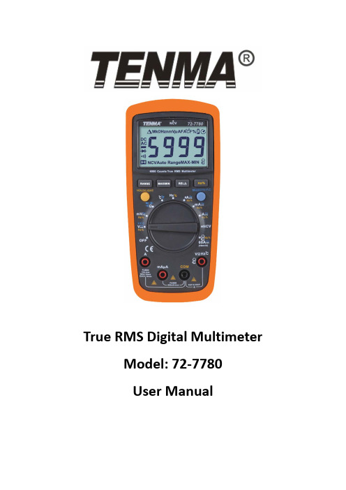
True RMS Digital Multimeter Model: 72‐7780User ManualI. Overview72‐2800 is a professional handheld true RMS multimeter with wide scope of application. It is a safe, stable and reliable measurement device for AC/DC, resistance, diode, continuity, capacitance, frequency, NCV measurement etc.II. Unpacking InspectionOpen the package box and take out the device. Please check whether the following items are deficient or damaged and contact your supplier immediately if they are. •User manual‐‐‐‐‐‐‐‐‐‐‐‐‐‐‐‐‐‐‐‐‐‐‐‐‐‐‐‐1pc•Test leads‐‐‐‐‐‐‐‐‐‐‐‐‐‐‐‐‐‐‐‐‐‐‐‐‐‐‐‐‐‐‐‐1pair•K‐type thermocouple‐‐‐‐‐‐‐‐‐‐‐‐‐‐‐‐1pc•Optional current clampIII. Safety informationSafety Standards•EN 61010‐1:2010•CAT III 600V, double insulation standard, over voltage standard, and RoHS, pollution grade IIPlease read and comply with the safety information carefully, or the protection provided by the device may be impaired.1.Do not use the device if the rear cover is not covered up or it will pose a shockhazard2.Do not use the device if the device or test leads appear damaged or if yoususpect that the device is not operating properly. Pay particular attention to the insulation layers.3.To avoid false reading, replace the battery when the battery indicatorappears.4.Functional dial should be switched to proper position.5.Never input voltage and current exceeding the value listed on the device.6.Do not switch the functional dial during measuring.7.After each measure, disconnect the test leads with the circuit. For measuringcurrent, switch off the power supply before test leads disconnection, especially important for measuring large current.e caution to measure voltage >DC 60V or AC 30Vrms.9.Do not use or store the device in high temperature, high humidity, flammable,explosive or strong magnetic field environments.10.Do not change the internal circuit of the device in order to avoid the damage tothe device and users.e damp cloth to clean the case; do not use detergent containing solvents orabradants.IV. SymbolsLow batteryBuzzer indicatorV.1)Max voltage between input terminals and earth grounding: See TechnicalSpecifications2)Fuse Type:10A Jack: F 10A H 600V Fuse (Φ6x25) mmmA/μA Jack: F 600mA H 600V Fuse (Φ6x32) mm3)Max Display Value:Capacitance measurement: 9999Frequency measurement: 9999Other measurement: 6000Duty Ratio:1~99.9%Diode: 3.2VOthers:1)Range: Auto/Manual2)Polarity: Auto3)Display updates 2~3 times for every second. Overrange Indicator: “OL”4)Operating temperature: 0˚C~40˚C (32˚F~104˚F)Storage temperature: ‐10 ˚C~50 ˚C (14 ˚F~122 ˚F)Relative humidity: ≤75% at 0 ˚C~30 ˚C; ≤50% at 30 ˚C~40 ˚C5)Operating altitude: 0~2000m6)Battery type: AA R6P 1.5V×27)Low power indicator:8)Dimension: 175mm×80mm×48.5mm9)Weight: 350g (batteries included)10)Electromagnetic compatibility:RF≤1V/m, overall accuracy=specified accuracy+5% of range.RF>1V/m, no specified calculation.VI. Structure (see figure 1)1/ Protective case2/Display screen3/4/7 Functional buttons5/Functional dial6/ Input jacksVII. Display━AutoΩHzVIII.V、V、Hz%˚C/mA 60ANCV Non‐contact voltageOFF shutdownButtons:RANGE:Switch the range mode to auto/manual and then cycle through all ranges. To exit auto/manual mode, press the button for 2 seconds or switch the functional dial. (Only for V,Ω,I measurement)MAX/MIN:Starts and stops Max/Min recording. To exit this mode, press the button for 2 seconds or switch the functional dial. (Only for V,Ω,I and ˚C /˚Fmeasurement)REL:Save the first reading as reference value. The second reading=second measurement value‐reference value. To exit his mode, press the button for 2 seconds. (Only for V,Ω,I and ˚C /˚F and measurement); when measuring capacitance,REL button is only used for eliminating intrinsic value.Hz/%:When measuring AC voltage/ current, press the button to cycle through frequency and duty ratio measurement.SELECT:Select functions. Under AC modes, long press the button until UFC appears to enter VFC measurement mode and measure the variable frequency voltage. Long press gain to exit VFC measurement mode.HOLD:Press the button once to hold the reading. Press again to unlock the reading and enter general measurement modes.IX. Operation instructionsTo avoid false reading, replace the battery if the battery low power symbolappears. Also pay special attention to the warning sign besides the test lead housing, indicating that the tested voltage or current must not exceed the valueslisted on the device.1. AC/DC voltage measurement (see Figure 3)1)Connect test leads with the load in parallel.2)When input impedance about 10MΩ, there ismeasurement errors. Input impedance≤10 kΩ,measurement errors can be ignored (≤0.1%)Notes:•Do not measure voltage over 600Vrms, or it may exposeusers to electric shock and damage the device.•Please pay extra attention when measuring high voltage inorder to avoid electric shock.2. Resistance measurement (see figure 4a)test leads with the resistance in parallel.•If the resistor is open or over the range, the “OL” symbolwill be displayed on the screen.•Before measuring resistance, switch off the power supplyof the circuit, and fully discharge all capacitors.•When measuring low resistance, the test leads will produce0.1Ω~0.2Ω measurement error. To obtain accuratemeasurement, short the test leads and use REL function.•If the resistance when shorted is more than 0.5Ω, please check if test leads are loosened or damaged.•When measuring high resistance above 60MΩ, it is normal to take a few seconds to steady the readings.•Resistance measurement can be used to inspect device’s internal fuses.( see figure 4b)•Do not input voltage over DC 60V or AC30V.3. Continuity measurement (see figure 5)If the resistance being measured is over 150Ω, circuit is in openstatus, buzzer does not go off. If the resistance less than 10Ω,circuit is in good conduction status, buzzer will continuously go off.Note:•To avoid damage to the device, before measuring continuity,switch off all power supplies and fully discharge all capacitors.•Do not input voltage over DC 60V or AC30V.4. Diode measurement (see figure 6)“OL” symbol appears when the diode is open or polarity isreversed.For silicon PN junction, normal value: 500 ~ 800mV (0.5 ~ 0.8V).Notes:•Switch off the power supply to the circuit, and fully dischargeall capacitors•Voltage for testing diode is about 3.1 V.•Do not input voltage over DC 60V or AC30V.5. Capacitance measurement (see figure 7)When there is no input, the device displays a fixed value(intrinsic capacitance). For small capacitancemeasurement, to ensure measurement accuracy, themeasured value must be subtracted from intrinsiccapacitance. Or users can measure small capacitycapacitors with relative measurement function (REL) (thedevice will automatically subtract the intrinsic•If the tested capacitor is shorted or its capacity is over the specified range “OL” symbol will bedisplayed on the screen.•When measuring large capacitors, it may take a few seconds to obtain steady readings.•Before measuring capacitors (especially for high voltage capacitors), please fully discharge them.6. Frequency/Duty ratio measurement (see figure 8) At the frequency position, press the Hz/% to select frequency/duty ratio measurement mode.Notes:•Do not input voltage over DC 60V or AC30V.7. Temperature measurement (see figure 9)Turn on the device, after “OL” symbol appears, insert K‐thermocouple into the device.Note:Only K‐type thermocouple is applicable. The measured temperature should be less than 230˚C/ 446˚F(˚F=˚C*1.8+32)8. AC/DC current measurement (see figure 10) Connect test leads with the tested circuit in series. Readings under this AC measurement is true RMS.•Before measuring, switch off the power supply of the circuit.•If the range of the measured current is unknown, select the maximum range and then accordinglyreduce.•There are fuses inside 10A jack and mA/μA jack. Do not connect the test leads with any circuits inparallel.•If the tested current is over 5A, each measurement time should be less than 10 seconds and the nexttest should be after 15 minutes.•When measuring AC current, press Hz/% button to display AC frequency or duty ratio.•60A AC and DC current clamp measurement (see figure 11)Connect as shown with the attached current clamp.9. NCV measurement (see figure 12)1)Switch the dial to NCV position2) Place the device near the measured object.“‐“ symbol indicates the intensity of the electricfield. More “‐“ and the higher the buzzer frequency,the higher the electric field intensity.3) Intensity of electric field* "EF": 0 ~ 50mV* "‐": 50 ~ 100mV* "‐‐": 100 ~ 150mV* "‐‐‐": 150 ~ 200mV* "‐‐‐‐":> 200mV .Notes:Test leads are not required for NCV measurement.10. Others• The device enters measurement status in 2 seconds after startup. Restart thedevice,”ErrE” appears.• The device automatically shuts down if there is no operation for 15 minutes.You can wake up the device by pressing any key. To disable auto shutdown,switch the dial to OFF position, long press SELETE button and turn on the device.symbol will disappear with one long beep. Recover the auto ‐off function byrestarting the device.• Buzzer notification1) Input voltage ≥ 600V (AC /DC), buzzer will continuously beep indicating measurerange is at limit2) Input current > 10A (AC/DC), buzzer will continuously beep indicating measurerange is at limit• Low power warnings: Voltage of the battery < 2.4V, symbol appears, thedevice can still be used. If voltage is lower than2.2V, the device cannot work andthe symbol disappears after startup.• The screen backlight cannot work if battery voltage less than 2.6V.X. Technical specificationAccuracy: ± (% of reading + numerical value in least significant digit slot), 1 YearWarrantyAmbient temperature: 23˚C±5˚C (73.4˚F±9˚F)Ambient humidity: ≤75% RH1. DC voltageRange Resoluti onAccuracy 60.00mV* 0.01mV ±(0.5%+2) 600.0mV** 0.1mV6.000V 0.001V±(0.7%+3) 60.00V 0.01V 600.0V 0.1V600V 1VInput impedance: about 10M Ω.Results might be unstable at mV range when no load is connected. The valuebecomes stable once the load is connected. Least significant digit ≤±3Max input voltage: ±600V, when the voltage ≥ 600V, "OL” symbol appears and thebuzzer goes off.”2.AC voltageRange Resolution Accuracy60.00mV 0.01mV ±(1.0%+3) 600.0mV 0.1mV6.000V 0.001V±(0.8%+3) 60.00V 0.01V600.0V 0.1V600V 1V ±(1.0%+3)VFC 200.0V~600V 0.1/1V ±(4.0%+3)Input impedance: about 10M ΩDisplay true RMS. Frequency response: 45Hz ~1KHz (LPF 45~400Hz)Accuracy guarantee range: 5 ‐100% of the range, shorted circuit allows leastsignificant digit ≤10 Crest factor at Max range=3.0 (excluding 600Vrange, crest factor=1.5)Max input voltage: 600Vrmstest leadsOpen circuit voltage=1V (Current=0.4mA)Overload protection:600V ‐PTCTest capacitance≤100nF, adapt REL mode.Input range: (DC level=0)≤100kHz: 100mVrms≤a≤20Vrms> 100 kHz~1MHz: 200mVrms≤a≤20Vrms>1MHz: 500mVrms≤a≤20Vrms>5MHz~10MHz: 1Vrms≤ a ≤20VrmsDuty ratio%:Only for frequency measurement≤100kHzNotes:When measuring AC voltage or current, following conditions should be satisfied:Frequency response≤1kHzAC voltage: mV position≥100mV; V position≥Range×6%AC current: input range: 4000/6000μA, 400/600mA, 10A: A≥range×6%400/600μA, 40/60mA, 4/6A:A≥range×60%•K‐type thermocouple is only applicable for temperature less than 250˚C/482˚F.μA mA range: F1Fuse (φ6×32)mm FF 600mA H 600V10 A range:F2Fuse (φ6×25)mm FF 10A H 600V 9. AC currentRange Resolution AccuracyμA600.0μA 0.1μA±(1.0+3) 6000μA 1μA mA 60.00mA 10μA 600.0mA 0.1mAA 6.000A 1mA ±(1.2%+3) 10.00A 10mAFrequency response: 45~1kHzDisplay: true RMSAccuracy guarantee range: 5 ‐100% of the range, shorted circuit allows least significant digit ≤2Crest factor at Max range=3.0Overload protection: (similar to DC current)XI. MaintenanceWarning: Before opening the rear cover, switch off the power supply (remove test leads from the input terminal and the circuit).1. General maintenance1) Clean the case with a damp cloth and detergent. Do not use abradants or solvents2) If there is any malfunction, stop using the device and send it to maintenance.3) The maintenance and service must be implemented by qualified professionals ordesignated departments.2. Replacements (see Figure13)Battery replacement:To avoid false reading, replace the battery when thebattery indicator appears.Battery Specification: AA 1.5Vx21) Switch the dial to “OFF “position and remove thetest leads from the input terminal.2) Take off the protective case. Loosen the screw onbattery cover; remove the cover to replace thebattery. Please identify the positive and negativepole.Fuse replacement:1) Switch the dial to “OFF “position and remove the teat leads from the input terminal2) Loosen the both screws on the rear cover, and then remove the rear cover to replace the fuseFuse specificationF1 Fuse φ6×32mm FF 600mA H 600VF2 Fuse φ6×25mm FF 10A H 600VTenma Test Equipment405 S. Pioneer Blvd.Springboro, Oh。
PD70211EVB72FW-12 72W 隔离前向转换器评估板用户指南说明书
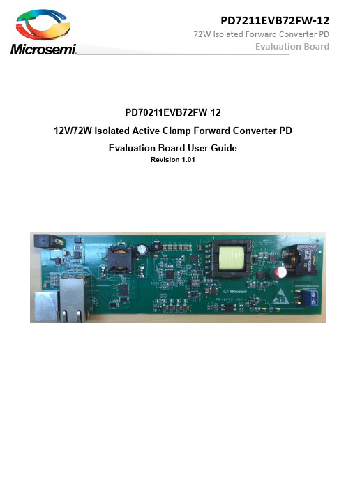
PD70211EVB72FW-1212V/72W Isolated Active Clamp Forward Converter PD Evaluation Board User GuideRevision 1.011 About this guideThis user guide provides both description and operation procedures for Microsemi's PD70211EVB72FW-12 evaluating board. This board is used for evaluating the performance of PD70211A PD controller with integrated switching regulator, and PD70224 Dual MOSFET – Based Active Bridge Rectifier.PD70211ILQ device supports both the standard IEEE802.3at PD application interface, and a PWM controller that is used to provide the PD operational voltage.The evaluation board supports a 72 Watt, 12V output in its existing configuration, with no heat sink, at room temperature.1.1 AudienceThis user guide is intended for qualified personnel, meaning operators and technicians who have a background in basic concepts of electronics.1.2 OrganizationThis guide is divided into several sections as follows:1.3 Reference DocumentsPD70211 datasheet, catalogue number DS_PD70211PD70224 datasheet, catalogue number DS_PD70224PD System Layout Guidelines, catalogue number AN208Implementing Auxiliary Power in PoE, catalogue number TN_2142 IntroductionMicrosemi’s PD70211ILQ device is part of a family of devices which are targeted for realizing the 802.3at standard PD interface.The PD interface family of devices includes the following:Microsemi’s PD70211EVB72FW-12 Evaluation Board (see Figure 2) provides designers with an environment needed for evaluating the performance and implementation of PD applications based on PD70211 controller.The board is using a single PD controller, PD70211ILQ, to support the Detection, Class, and Power Supplying phases on the 4 Pairs of the Cat5 cable. The board supports sync detection of the 4 pairs. PD70211ILQ supports the current of the HDBaseT over 4 Pairs, which is more than twice the power of a standard IEEE802.3AT Type 2 interface.All necessary steps and connection instructions required to install and operate this board are provided within this document.Figure 1: PD70211EVB72FW-12 Block DiagramFigure 2: PD70211EVB72FW-12 Evaluation Board – General ViewEvaluation Boards Ordering InformationMicrosemi supplies the following Evaluation Board as shown below:2.1 Evaluation Board Features▪Designed to support Data and Spare current by a single PD70211A device▪Power is supplied through the 4-pairs of the Cat5 cable▪Wall Adapter input –Standard Barrel Jack available for connecting to an external 48-54V Wall Adapter.▪Data pass-through connector▪On board PSE class type LED indicators▪On board AT detected LED indicator▪On board 4P_AT detected LED indicator▪On board HD detected LED indicator▪On board 4P_HD detected LED indicator▪On board Power Good LED indicator which may be configured to monitor PD Front End or VPP UVLO.▪Ta: -40° to +70°C (with derating curve)▪RoHS compliant2.2 Physical CharacteristicsTable 1 lists evaluation board’s physical characteristics.Table 1: Physical Characteristics3 Physical Description3.1 Package ContentsUpon opening the Evaluation Board package, verify the following part is included.If it seems damaged, contact local representative or Microsemi's headquarters.Package content for standard shipments is:▪PD70211EVB72FW-12 Evaluation Board.▪Wall Adapter Input Cable3.2 ConnectorsThe following sections provide both general and detailed information regarding unit’s connectors.3.2.1 Connectors TableTable 2 lists the Evaluation Board's connectors.Table 2: Connectors List3.2.2 Connectors Detailed Explanation(The numbering is in reference to the numbers listed in Table 2.)1. RJ45 Connectors.SeeFigure 3.Table 3: RJ45 ConnectorsFigure 3: Front RJ45 and Auxiliary 48V Wall Adapter Connectors2. Wall Adapter ConnectionsSee Figure 3.3. V out ConnectionsSee Figure 4.Table 4: Output Load ConnectionsFigure 4: V out Connections3.3 IndicationsThe following sections provide general information regarding unit’s indications.1. LED IndicationSee Figure 5.3.3.1.1 LED IndicationSee Figure 5.D16 is the AT_FLAG indication LED, a PD70211 device output signal indicating the device has detected a 2 finger class event from the PSE side in the class stage. The flag will be operative at 3, 4, and 6 fingers detection as well. D15 is the 4P_AT indication LED, a PD70211 device output signal indicating the device has detected a 4 finger class event from the PSE side in the class stage, or a 2 finger class event from the PSE side in the class stage, and SUPP_SA and SUPP_SB are both High.The flag will be operative at 6 fingers detection as well.D20 is the HD_FLAG indication LED, a PD70211 device output signal indicating the device has detected a 3 finger class event from the PSE side in the class stage.The flag will be operative at 6 fingers detection as well.D19 is the 4P_HD indication LED, a PD70211 device output signal indicating the device has detected a 6 finger class event from the PSE side in the class stage.D14 is the Power Good indication. This LED indicates the presence of power. This indicator may be configured to monitor PD Front End VAUX (Asserts when VPP = 36V min.; de-asserts when VPP = 31V min.), or it may be configured to monitor the VPP UVLO, which is user selectable by the resistor values at VINS and HYST pins (R13, R19, and R25). See the PD70211 datasheet for further details regarding setting VPP UVLO limits. EVB default forPower Good EVB is monitoring VPP UVLO, and will track the operation of the DC-DC converter. To change Power Good to monitor PD Front End VAUX:1) Remove R51, 100 Ohm Resistor (located on top of PCB near D19).2) Add R50 Zero Ohm Jumper (also located on top of PCB near D19).3) Insure that only R51 or R50 are installed; do not operate with both resistors installed.Figure 5: LED Indications4 Electrical CharacteristicsE valuation board’s electrical characteristics are described below:Table 5: Electrical Characteristics*After start-up, the minimum voltage is 36V with load ≤ 13W per IEEE specification.5 Installation5.1 Preliminary Considerations and Safety PrecautionsIf using an external supply in place of a PSE, verify the external power supply is turned “off”before all peripheral devices are connected. Insure the external supply is connected to theRJ45 input (J1) per Table 3.5.2 Initial ConfigurationNote: It is important to verify evaluation board is setup as shown in Figure 6 prior to starting any operation.1. Connect load to evaluation board (J3 -1 (+) & J3 – 2 (-), or TP17 (+) & TP16 (-)).2. Connect a Cat5 cable from PSE to Evaluation Board (J1), or a 48V Wall Adapter to Evaluation Board (J2). Note: Wall Adapter will override power from PSE.Figure 6: Test Setup6 Test DataThis chapter describes typical EVB test data under various loads and POE input voltage levels.The efficiency is indicated up to 72W output power.Overall efficiency is measured at the input to the bridge. It does not include system-level components (input/output connectors, data transformer, and EMI filter).DC-DC efficiency is measured after the PD chip.6.1 Efficiency vs. Input Voltage to the bridge at full load (72W output)Figure 7: Efficiency vs. Input Voltage6.2 Efficiency vs. Load Current at 48V Input to the bridgeFigure 8: Efficiency at 48V Input6.3 Efficiency vs. ambient temperature at 48V inputFigure 9: Efficiency vs. temperature at 48V Input6.4 Output Ripple measured with 20MHz bandwidthFigure 10: Full Load Voltage Ripple and Noise at 48V Input (100mV/div)6.5 Bode Plots at full load at 48VinFigure 11. Bode plotsPhase Margin: 80°Gain Margin: -22 dB6.6 Step Load Response for transitions between 10% load and 100% load (riseand fall time 100us)Figure 12: Load Step Response (100mV/div)7 SchematicFigure 13: Evaluation Board Schematic (1 of 2)DATA OUT10n R126PD-1206D32SMBJ58CA PD-SMBD33SMBJ58CA PD-SMBOPTIONAL FOR COMMON MODE SURGE PROTECTION12345678J4RJ45-I1122334455667788991010Data3Data4Data1Data2Data6Data7Data8Data5J2Figure 14: Evaluation Board Schematic (2 of 2)N.C = NOT CONNECTED (OPTIONAL)8 List of Materials9 Board LayoutThis section presents the layout of the evaluation board.The board is a 2 layer board. All layers are 2 Oz copper. Below figures present the copper layers and the silk of the board for tracking devices placements.Figure 15: Top Silk and Solder MaskFigure 16: Bottom Silk and Solder Mask (Image Looking From Bottom)Figure 17: Top LayerFigure 18: Bottom LayerThe information contained in the document (unless it is publicly available on the Web without access restrictions) is PROPRIETARY AND CONFIDENTIAL information of Microsemi and cannot be copied, published, uploaded, posted, transmitted, distributed or disclosed or used without the express duly signed written consent of Microsemi. If the recipient of this document has entered into a disclosure agreement with Microsemi, then the terms of such Agreement will also apply. This document and the information contained herein may not be modified, by any person other than authorized personnel of Microsemi. No license under any patent, copyright, trade secret or other intellectual property right is granted to or conferred upon you by disclosure or delivery of the information, either expressly, by implication, inducement, estoppels or otherwise. Any license under such intellectual property rights must be approved by Microsemi in writing signed by an officer of Microsemi.Microsemi reserves the right to change the configuration, functionality and performance of its products at anytime without any notice. This product has been subject to limited testing and should not be used in conjunction with life-support or other mission-critical equipment or applications. Microsemi assumes no liability whatsoever, and Microsemi disclaims any express or implied warranty, relating to sale and/or use of Microsemi products including liability or warranties relating to fitness for a particular purpose, merchantability, or infringement of any patent, copyright or other intellectual property right. Any performance specifications believed to be reliable but are not verified and customer or user must conduct and complete all performance and other testing of this product as well as any user or customers final application. User or customer shall not rely on any data and performance specifications or parameters provided by Microsemi. It is the customer’s and user’s responsibility to independently determine suitability of any Microsemi product and to test and verify the same. The information contained herein is provided “AS IS, WHERE IS” and with all faults, and the entire risk associated with such information is entirely with the User. Microsemi specifically disclaims any liability of any kind including for consequential, incidental and punitive damages as well as lost profit. The product is subject to other terms and conditions which can be located on the web at /company/terms-and-conditionsRevision History© 2016 Microsemi Corp.All rights reserved.For support contact: ************************Visit our web site at: Catalog Number: PD70211EVB72FW-12_UG_EVB。
konica7216 7220维修手册要点

Kinica7216\7220 现场维修Ver.1.0 Mar. 2004 调整/ 设定4. 技术维修模式• 技术维修模式用来检查、设定、调整或注册各种维修功能。
4.1 维修模式功能树_ 安装选购件时显示。
Service Mode(维修模式)一、SERVICE'S CHOICE(技术维修选择)1、SHIPMENT DESTINATION (市场地区)2、MAINTENANCE COUNTER (保养计数器)3、IU LIFE STOP MODE (IU 寿命终止模式)4、ID ADJUST (ID 调整)5、VG ADJUST (VG 调整)6、FUSER TEMP. Ad (PLAIN)(定影温度调整(普通纸))7、FUSER TEMP. Ad (THICK)(定影温度调整(厚纸))8、FUSER TEMP. Ad (OHP)(定影温度调整(OHP))9、LEADING EDGE ERAGE (前边缘消除)10、TRAILING EDGE ERAGE (后边缘消除)11、VERTICAL EDGE ERAGE (上下边缘消除)12、LOOP ADJUST (TRAY1)(波幅调整(第1 纸盒))13、LOOP ADJUST (TRAY2 TO TRAY5)*(波幅调整(第2 纸盒到第5 纸盒)*)14、LOOP ADJUST (DUPLEX)(波幅调整(双面))15、LOOP ADJUST (BYPASS)(波幅调整(手送进纸))16、FLS PAPER SIZE (FLS 纸张尺寸)17、CCD APS SIZE (CCD APS 尺寸)18、GDI TIMEOUT (GDI 超时)二、ADJUST (调整)1、PRN MAIN REGIST (打印主对位)2、PRN SUB REGIST (打印次对位)3、CCD MAIN ZOOM (CCD 主缩放)4、CCD SUB ZOOM (CCD 次缩放)5、CCD MAIN REGIST (CCD 主对位)6、CCD SUB REGIST (CCD 次对位)7、ADF SUB ZOOM (ADF 次缩放)8、ADF MAIN REGIST (ADF 主对位)9、ADF SUB REGIST1 (ADF 次对位1)10、ADF SUB REGIST2 (ADF 次对位2)11、ADF REG. LOOP 1 (ADF 对位波幅1)12、ADF REG. LOOP 2 (ADF 对位波幅2)13、ATDC GAIN (ATDC 增益)14、MODEL SETTING (模式设定)三、COUNTER (计数器)1、TOTAL COUNTER (总计数器)2、SIZE COUNTER (尺寸计数器)3、PM COUNTER (PM 计数器)4、MAINTENANCE COUNTER (保养计数器)5、SUPPLIES LIFE COUNT. (使用寿命计数)6、APPLICATION COUNTER (应用计数器)7、SCAN COUNTER (扫描计数器)8、PAPER SIZE COUNTER (纸张尺寸计数器)9、MISFEED COUNTER (卡纸计数器)10、TROUBLE COUNTER (故障计数器)四、DISPLAY (显示)1、TONER DENSITY LEVEL (碳粉浓度水平)2、PROCESS CONTROL (过程控制)3、MAIN F/W VER. (主机固件版本)4、ENGINE F/W VER. (引擎固件版本)5、PCL F/W VER.* (PCL 固件版本*)6、NIC F/W VER.* (网卡固件版本*)7、ADF F/W VER.* (ADF 固件版本*)8、MAIN RAM SIZE (主内存大小)9、PCL RAM SIZE* (PCL 内存大小*)10、SERIAL NO. (序列号)11、CUSTOMER ID (用户识别码)五、FUNCTION (功能)1、PAPER FEED TEST (送纸测试)2、PROCESS CHECK (过程检查)3、ATDC AUTO ADJUST (ATDC 自动调整)4、PRINT TEST PATTERN (打印测试图案)5、ADF FEED TEST (ADF 输稿测试)6、COPY ADF GLASS AREA(复印ADF 玻璃区域)7、CCD MOVE TO HOME (CCD 移到原位)8、SCAN TEST (扫描测试)9、ADF WIDTH ADJ. (MAX)*(ADF 宽度调整(最大)*)10、ADF WIDTH ADJ. (MIN)*(ADF 宽度调整(最小)*)11、ADF SENSOR ADJUST* (ADF 感应器调整*)六、ADMIN. REGISTRATION (管理员注册)七、FIXED ZOOM CHANGE(固定缩放修改)1、REDUCTION2 (缩小2)2、REDUCTION1 (缩小1)3、EXPANSION1 (放大1)4、EXPANSION2 (放大2)七、FIXED ZOOM CHANGE(固定缩放修改)八、FACTORY TEST(出厂测试)1、PANEL BUZZER TEST (面板蜂鸣器测试)2、RAM TEST (RAM 测试)九、CLEAR DATA (清除数据)1、MEMORY CLEAR (清除内存数据)2、PM COUNTER (PM 计数器)3、MAINTENANCE COUNTER (保养计数器)4、SUPPLIES LIFE COUNT. (使用寿命计数)5、APPLICATION COUNTER (应用计数器)6、SCAN COUNTER (扫描计数器)7、PAPER SIZE COUNTER (纸张尺寸计数器)8、MISFEED COUNTER (卡纸计数器)9、TROUBLE COUNTER (故障计数器)10、ADF BACKUP CLEAR*(ADF 备份数据清除*)十、SECURITY (安全性)1、TOTAL COUNTER COUNT (总计数器计数)2、SIZE COUNTER COUNT (尺寸计数器计数)3、PLUG-IN COUNTER COPY(接插式计数器复印)4、MACHINE COUNTER (机器计数器)注意• 必须注意只有专业维修人员才能进入维修模式。
Anti-HiBiT Monoclonal Antibody n7200 N7210 使用说明书

2023版 CTM719原英文技术手册TM719中 文 说 明 书适用产品目录号:N7200、N7210Anti-HiBiT Monoclonal Antibody普洛麦格(北京)生物技术有限公司Promega (Beijing) Biotech Co., Ltd 地址:北京市东城区北三环东路36号环球贸易中心B座907-909电话:************网址:技术支持电话:400 810 8133技术支持邮箱:*************************CTM7192023制作1所有技术文献的英文原版均可在/ protocols 获得。
请访问该网址以确定您使用的说明书是否为最新版本。
如果您在使用该试剂盒时有任何问题,请与Promega 北京技术服务部联系。
电子邮箱:*************************1. 描述 (2)2. 产品组分和储存条件 (3)3. 免疫印迹分析 (3)3. A. 一般注意事项 (3)3. B. 示例操作流程 (4)3. C. 示例数据 (5)4. 免疫荧光分析 (7)4. A. 一般注意事项 (7)4. B. 示例操作流程 (8)4. C. 示例数据 (9)5. 免疫沉淀 (10)5. A. 一般注意事项 (10)5. B. 示例操作流程 (11)5. C. 示例数据 (12)6. 用活细胞进行荧光激活细胞分选(FACS) (15)6. A. 一般注意事项 (15)6. B. 示例操作流程 (15)6. C. 示例数据 (17)7. 用固定细胞进行荧光激活细胞分选 (17)7. A. 一般注意事项 (17)7. B. 示例操作流程 (18)7. C. 示例数据 (19)8. 抗体结合亲和力和与LgBiT的竞争 (19)9. 疑难排查 (21)9. A. 免疫印迹分析 (21)9. B. 免疫荧光分析 (22)9. C. 免疫沉淀 (22)9. D. 荧光激活细胞分选 (23)10.参考文献 (24)11.相关产品 (24)Anti-HiBiT Monoclonal Antibody普洛麦格(北京)生物技术有限公司Promega (Beijing) Biotech Co., Ltd 地址:北京市东城区北三环东路36号环球贸易中心B座907-909电话:************网址:技术支持电话:400 810 8133技术支持邮箱:*************************CTM7192023制作21.描述HiBiT蛋白标签为含有11个氨基酸的多肽,在NanoLuc® Binary Technology(NanoBiT®)中,可与大亚基(LgBiT)以高亲和力结合,以重建NanoBiT®萤光素酶,一种明亮的发光酶(1,2)。
- 1、下载文档前请自行甄别文档内容的完整性,平台不提供额外的编辑、内容补充、找答案等附加服务。
- 2、"仅部分预览"的文档,不可在线预览部分如存在完整性等问题,可反馈申请退款(可完整预览的文档不适用该条件!)。
- 3、如文档侵犯您的权益,请联系客服反馈,我们会尽快为您处理(人工客服工作时间:9:00-18:30)。
C-06-072-X3C0602 期 發行編號
版次 頁數 日 1 3
2007.08.23
*********************** * 7120 AC&DC 高壓測試儀操作指導書 * * * ***********************
標準 承認
校 對
製 表
華容電子(昆山)有限公司
[文件修訂記錄表]
文件名稱: 7120 AC&DC 高壓測試儀操作指導書
文件編號:
C-06-072-X3C0602
校對 標準 ECN 編號 承 認 連絡書編號
版 本
1
變
更
內
頁 (發行) 容 (數) 變更日期 次
製表
首次發行
3 2007/08/23
華容電子(昆山)有限公司
文 件 名 稱
停止/復位 測試 顯示器
電源
設置
上
下
返回
適用 全公司 標準 承認
頁次 校 對
2/3
版72-X3C0602 製表 日期 2007.08.23
華容電子(昆山)有限公司
文 件 名 稱
7120
AC&DC 高壓測試儀操作指導書
7 附件: 7-1.品管部儀器設備保養記錄表 7-2.進料檢驗記錄表 PQ048*1 PQ001*1
1/3
版次 製 表
1
標準編號 C-06-072-X3C0602 製表 日期 2007.08.23
華容電子(昆山)有限公司
文 件 名 稱
7120
AC&DC 高壓測試儀操作指導書
6-4.注意事項: a.不要將測試儀器放置於多灰塵或震動場所,周圍溫度為 0~30℃, 且相對濕度低於 70% b.測試時不要用手去觸摸測試夾.且測試時測試夾不可有短路現象。 6-5.保養: a:保持儀器清潔,儀器表面不可有異物、灰塵 等 b.使用前檢查連接線是否緊密,使用後注意關掉電源 6-6.功能鍵說明: a.RESET 鍵:停止/復為 b.TEST 鍵:測試 c.SET 鍵:設置 d.V 鍵:上鍵 e.^ 鍵: 下鍵
適用 全公司 標準 承認
頁次 校 對
3/3
版次 製 表
1
標準編號 C-06-072-X3C0602 製表 日期 2007.08.23
7120
AC&DC 高壓測試儀操作指導書
1.目的:為確保本公司產品品質與可靠性,廠內儀器之正確使用操作的 一致性, 2. 範圍: 2-1.7120 AC&DC 高壓測試儀器適用之. 3. 權責: 3-1.品保部:負責儀器的操作和管理. 4. 5. 6. 名詞定義:無 相關文件:無 步驟說明: 6-1. 開機(POWER ON). 6-2. 按上下鍵選擇和設定測試類別: a. Memory:設定模式(可設定和存儲 5 組資料). b.W-Mode:高壓模式, 按上、下鍵選擇 AC&DC(AC:0-6000V DC:0-5000V) d.W-High:漏電流上限,按上、下鍵選擇. e.W-Low: 漏電流下限, 按上、下鍵選擇. f.W-Ramp:電壓延時上升時間. g.W-Dwell:測試時間. h.W-Arc:電弧測試. j.測定完畢后按 RESET 鍵退出設定. 6-3:測試: a.將測試夾夾住待測品,按 TEST 鍵. b.短鳴且 TEST 鍵亮綠燈為合格,長鳴且 RESET 鍵亮紅燈為不良 c.將測試結果記錄於報表中 d.儀器不用時將關閉電源 適用 全公司 標準 承認 頁次 校 對
