光纤通信系统Optical_Fiber_Communications_英文资料及中文翻译
光纤通信(Optical Fiber Communication)Analog Systems PPT课件

CONTENT
For transmitting multiple signals over the same channel, one can use a sub carrier modulation technique. In this method, which is described in Sec. 9.3,the information signals are first superimposed on ancillary RF sub carriers. These carriers are then combined and the resulting electrical signal is used to modulate the optical carrier. A limiting factor in these systems is the signal impairment arising from harmonic and intermodulation distortions.
CONTENT
CHAPTER 9
ANALOG SYSTEMS
9.3 MULTICHANNEL TRANSMISSION TECHNIQUES 9.3.1 Multichannel Amplitude Modulation 9.3.2 Multichannel Frequency Modulation 9.3.3 Subcarrier ERVIEW OF ANALOG LINKS
CONTENT
9.2 CARRIERTO-NO1SE RAT1O
In analyzing the Performance of analog systems, one usually calculates the ratio of rms carrier power to rms noise power at the input of the RF receiver following the photodetection process. This is known as the carrier-noise ratio (CNR). Let us look at some typical CNR values for digital and analog data. For digital data, consider the use of frequency-shift keying (FSK). In this modulation scheme, the amplitude of a sinusoidal carrier remains constant,{but the phase shifts from one frequency to another to represent binary signals. For FSK, BERs of10-9 and10-15 translate into CNR values of 36 (l5.6 dB) and 64 (l8.0 dB), respectively. The analysis for analog signals is more complex, since it sometimes depends on user perception of the signal quality, such as in viewing a television picture. A widely used analog signal is a 525-line studio-quality television signal. Using amplitude modulation (AM) for such a signal requires a CNR of 56 dB, since the need for bandwidth efficiency leads to a high signal-to-noise ratio. Frequency modulation (FM), on the other hand, only needs CNR values of l5-l8 dB. If CNRi represents the carrier-to-noise ratio related to a particular signal contaminant (e.g., shot noise), then for N signal-impairment factors the total CNR is given by
光通讯英文缩写
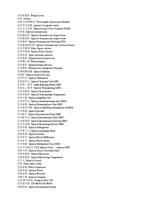
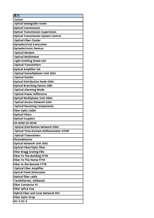
光泵浦器件Pump Lasers光标Cursor光波长转换模块Wavelength Conversion Modules光波导分波器optical waveguide router光层交叉连接Optical Layer Cross Connect OLXC光传输Optical transmission光传输监控Optical Transmission Supervision光传输监控Optical Transmission Supervision光传输网Optical Transmission Network OTN光传输系统控制Optical Transmission System Control 光导纤维束Fiber Optics cluster光导纤维束Optical Fiber Cluster光电处理Opto-electronic process光电端机Optoelectrical transceiver光电耦合器Photocouplers光电器件Optoelectronic Devices光电整机Photoelectric Integrated Machine光调制解调器Optical Modem光端机Optical transceiver (ln)光多用表Optical Multimeter光发射单元Optical Transmit Unit OIU光发射二级管Light Emitting Diode LED光发送二极管Optical Transmitting LEDs光发送模块Opitcal Transmitters光发送器件Optical Transmitting Components光放大器Optical Amplifier OA光分波单元Optical demultiplexing unit (ODU)光分波器Optical Demultiplexer Unit ODU光分插复用器Optical Add/Drop Multiplexer OADM 光分路器Optical Divider光分配点Optical Distribution Point ODP光分配节点Optical Distribution Node ODN光分配网络Optical Distribution Network ODN光分支装置Optical Branching Device OBD光复用器Optical Multiplexer光告警方式Optical Alarming Mode光隔离器Optical Isolator光功率差Optical Power Difference光功率计Optical Power Meter光合波板Optical Multiplexer Unit OMU光交叉连接(光互联) Optical Cross-connect OXC光接入网Optical Access Network OAN光接收模块Optical Receivers光接收器件Optical Receiving Components光开关Optical Switch光缆Fiber Optic Cable光连接器Fiber Connectors光滤波器Optical Filters光敏电阻Optical Resistor光耦合器Optical Couplers光盘.激光唱盘Compact Disc CD光盘驱动器CD-ROM CD-ROM光配线架Optical Distribution Frame光配线网Optical Distribution Network ODN光前置放大板Optical Preamplifier OPA光时域反射计Optical Time-Domain Reflectometer OTDR光收发板Optical Transceiver Board OTB光收发模块Optical Transceivers光输入口允许频偏Permitted frequency deviation of optical input interface 光探测器Photodetector光通道Optical channel OCh光网络单元Optical Network Unit ONU光无源器件Optical Passive Devices光纤Optical Fiber/Optic fiber光纤包层Cladding of Fiber光纤布拉格光栅Fiber Bragg Grating FBG光纤到办公室Fiber To The Office FTTO光纤到大楼Fiber To The Building FTTB光纤到服务区Fiber To The Service Area FSA光纤到家Fiber To The Home FTTH光纤到路边Fiber To The Curb FTTC光纤到远端Fiber to the Remote FTTR光纤的Fiber-optic光纤放大器Optical Fiber Amplifier光纤分布式数据接口Fiber Distributed Data Interface FDDI光纤固定衰减器Optical Fixed Attenuator光纤管道Fiber Conduit光纤光缆Optical fiber cable光纤光栅Fiber Grating光纤基带快速以太网FastEthernet, 100baseX光纤接口Fiber Interface FBI光纤连接器Fiber Connector FC光纤耦合器Fiber Coupler光纤熔接盒Fiber splice tray光纤衰减器Fiber Attenuator光纤同轴混合网Hybrid Fiber and Coax Network HFC光纤尾纤Fiber Pigtail光纤引入线Fiber Optic Drop光纤用户环路Fiber In The Loop光纤载波等级3 OC-3 OC-3光线路Optical Line OL光线路板Optical Line Board OL光线路放大器Optical Line Amplifier OLA光线路收发板Optical Line Transceiver Board OLT光线路终端Optical line terminal OLT光信号Optical Signal光学器件Optics光学字符识别Optical Character Recognition OCR光载波第1级Optical Carrier Level 1 OC-1光载波第N级Optical Carrier Level N OC-N光栅(fiber) grating光支路接口optical tributary interface光支路接口单元optical interface units。
光通信中英文对照(Word最新版)

光通信中英文比照通过整理的光通信中英文比照相关文档,渴望对大家有所扶植,感谢观看!光纤:optical fiber; fibergrat ing:光栅OFC :光缆GIF :渐变型光纤SIF:阶越型光纤DSF:色散位移光纤DCF:色散补偿光纤DFF:色散平坦光纤POF:塑料光纤(Plastic Optical Fiber)PCF:光子晶体光纤PANDA光纤:偏振保持光纤HNLF :高非线性光纤HCF:密封涂层光纤CCF:碳涂层光纤MCF :金属涂层光纤ECF:偏心光纤光纤阵列:fiber array; FA; FABU;BFA 光纤阵列模块:Fiber Array Block (FAB) AWG :阵列波导光栅FBT :熔融拉锥Coupler:耦合器平面波导型光分路器:PLC splitter熔融拉锥光纤分路器:Fused Fiber SplitterCW :连续Pump :泵浦Power :电源laser crystal:激光晶体PD:光电二极管LD :半导体激光器、激光二极管ILD :注入型半导体激光器LED :发光二极管Light Emitting DiodeDBR :分布式布拉格反射DFB :分布反馈DFB-LD :分布反馈式半导体激光器FP-LD:法布里-珀罗半导体激光器DSM-LD :动态单模半导体激光器SC:超连续光源(Super continuum)PA:前置放大器LA :线路放大器BA、PA:功率放大器OA :光放大器LNA :低噪声放大器OFA :光纤放大器SOA :半导体光放大器SRS:受激拉曼散射SRA(RFA):拉曼光纤放大器SBS:受激布里渊散射SBA :受激布里渊散射光纤放大器BRA(BFA):布里渊光纤放大器TDFA :掺铥光纤放大器(属掺杂稀土离子) EDFA :掺饵光纤放大器PDFA :掺错光纤放大器NDFA :掺铌光纤放大器IL :插入损耗RL :回波损耗EL :附加损耗TL :传输损耗PDL :偏振相关损耗BIL :弯曲附加损耗CR:分光比ER:消光比FL :匀整性PMD :偏振模色散、单模光纤中偏振色散EMB :有效模式带宽OFL :满注入带宽OM :光模式Optical ModeMFD :模场直径Isolator :隔离器Coupler:耦合器Connector:连接器Splitter :分路器Collimator :准直器Optical switch :光开关Attenuator :衰减器Modulator :调制器Filter :滤波器Receive :接收器OC :光载体、光纤载波CW :载波carrier waveOLT :光缆终端设备、局端机房设备ODN :光配线网络ONU :光节点、光网络单元ONT:光网络终端OTN :光传送网OTM :光终端复用器OUT:光转发器OTU :波长转换器OSU:光用户单元OXC :光交换节点ODF :光纤配线架DDF:数字配线架OT:输出终端PCM:电端机CO:中心局3U :超高速、超大容量、超长距离OAN :光纤接入网LAN :局域网MAN :城域网高速短距离的光纤通信系统WAN :广域网Metro networks :地下网路Ethernet:以太网Network :网络CUN :可持续网络NGN :下一代网络NPN :新公众网UN :一体化网ASON :自动交换光网络OAN :光接入网PON:无源光网络WDMPON :波分复用型无源光网络CDMA PON :码分多址型无源光网络PSPON:功率分割型无源光网络APON :BPON :宽带无源光网络Broadba nd PON EPON:以太无源光网络Ethernet PON GPO N:吉比特无源光网络Gigabit PONTDM :时分复用OTDM :光时分复用OADM :光分插复用(Optical Add-DropMultiplexer)CDM :码分复用FDM :频分复用WDM :波分复用Wavelength :波长Division :分开Multiplexer :多路(复用)器DWDM :密集波分复用CWDM :粗波分复用FWDM :滤波片式波分复用器HWDM :高隔离度波分复用器CDMA :码分多址(Code-division multiple access) SDMA :空分多址MUX :多路复用(multiplex)DEMUX :解复用(de-multiplex)GFF:增益平坦滤波器(gain flattening filter)bit :二进制位、比特Byte:字节、8位元组1字节=8比特ban dwidth :带宽、频宽baud:波特率bps (bit per second) : bit/sDFG :差频3R再生:再放大、再整形、再定时2R再生:再整形、再定时1R再生:再放大REG:再生器XGM :交叉增益调制XPM :交叉相位调制FWM :四波混频TOBPF:带通滤波器SPN::节点共享式SPL:链路共享式RZ:归零码NRZ :不归零码ASK :幅移键控FSK:频移键控PSK:相移键控IM-DD :强度调制-干脆检测PC:偏振限制器OC:光环形器PBS:偏振分束器GEQ :增益平坦器MTBF :平均无故障时间match gel:匹配液CamSplice:光纤接续子OTDR :光时域反射器ESA :激发态吸取DGD :微分群时延FTTH :光纤至U户Fiber To The Home FTTB :光纤到大楼FTTC :光纤到路边VOD :视频点播IPTV :即交互式网络电视CATV :有线电视网(接受模拟传输方式)Adapter:适配器connector:连接器Atte nu ator:衰减器Isolator:隔离器Transceive:收发器Coupler:耦合器光耦合器(OC)FIC :快速连接头field in stallable connector V-groove: V 型槽Source:源lamp-house:(仪器上的)光源Power Meter:功率计Photoelectric detector:光电探测器optical switch:光开关FVW :电子显微镜Adhesive:胶粘剂Optical Adhesive:光学胶黏剂Sett ing:测试I/O:开/关Bare:赤裸Bare Fiber :裸纤Ribbon Fiber :带状光纤Loose :宽松Tube:管Loose Tube : 松套管Tight :紧的Buffer :缓冲层Tight Buffer :紧缓冲层sin gle :单dual :双Multi- mode 多模Standard :标准storage:储存temperature 温度loss :损耗Fan-Out:输出端In put :输入Output:输出Special :特殊的Other :其他TLC :泰尔认证ITU-T :国际电信联盟远程通信标准化组织IEC :国际电工委员会ISO :国际标准化组织GB/T :举荐性国家标准Package :包装Dimension :尺寸Port :端口Type :类型Length :长度None :没有Six-axes stage六维微调架Backstop :支架Fixi ng :固定Precision:精密optical part :光学零件Side Pull :侧拉LSZH :聚烯烃PE :聚乙烯PVC :聚氯乙烯Metal : 属Steel :钢铁Stai nless Steel :不锈钢Plastic :塑胶PMMA :亚克力或者亚加力、有机玻璃。
光通信中英名词对照
双 标准 温度 输出端 输出 其他 国际电信联盟远程通信标准化组织 国际标准化组织 包装 端口 长度 六维微调架 固定 光学零件 聚烯烃 聚氯乙烯 钢铁 塑胶 片状模塑料 无规共聚聚丙烯 雪崩光电二极管 (本征)型二极管(PIN Diode)
Optical Line Board OL
Optical Line Transceiver Board OLT
Optical Signal
Optical Character Recognition OCR
Optical Carrier Level N OC-N
optical tributary interface
超高速、超大容量、超长距离 局域网 广域网 以太网 可持续网络 新公众网 自动交换光网络 无源光网络 码分多址型无源光网络 无源光网络 以太无源光网络 Ethernet PON 时分复用
光分插复用(Optical Add-Drop Multiplexer)
频分复用 波长 多路(复用)器 粗波分复用 高隔离度波分复用器 空分多址 解复用(de-multiplex) 二进制位、比特 带宽、频宽 bit/s 再放大、再整形、再定时 再放大 交叉增益调制 四波混频 节点共享式 归零码 幅移键控 相移键控 偏振控制器 偏振分束器 平均无故障时间 光纤接续子 激发态吸收 光纤到户Fiber To The Home 光纤到路边 即交互式网络电视 适配器 衰减器 收发器 快速连接头field installable connector 源 功率计 光开关 胶粘剂 测试 赤裸 带状光纤 管 紧的 紧缓冲层
optical fiber; fiber
OFC SIF DCF POF PANDA光纤 HCF MCF 光纤阵列 AWG Coupler 熔融拉锥光纤分路器 Pump laser crystal LD LED DFB FP-LD SC LA OA OFA SRS SBS BRA(BFA) EDFA NDFA RL TL BIL ER PMD OFL MFD Coupler Splitter Optical switch Modulator Receive CW ( carrier wave) ODN ONT OTM OTU OXC DDF PCM
中英对照:光纤通信

《光纤通信》光纤通信光纤常被电话公司用于传递电话、互联网,或是有线电视的信号,有时候利用一条光纤就可以同时传递上述的所有信号。
与传统的铜线相比,光纤的信号衰减(attenuation)与遭受干扰[来源请求](interference)的情形都改善很多,特别是长距离以及大量传输的使用场合中,光纤的优势更为明显。
然而,在城市之间利用光纤的通信基础建设(infrastructure)通常施工难度以及材料成本难以控制,完工后的系统维运复杂度与成本也居高不下。
因此,早期光纤通信系统多半应用在长途的通信需求中,这样才能让光纤的优势彻底发挥,并且抑制住不断增加的成本。
从2000年光通信(optical communication)市场崩溃后,光纤通信的成本也不断下探,目前已经和铜缆为骨干的通信系统不相上下。
对于光纤通信产业而言,1990年光放大器(optical amplifier)正式进入商业市场的应用后,很多超长距离的光纤通信才得以真正实现,例如越洋的海底电缆。
到了2002年时,越洋海底电缆的总长已经超过25万公里,每秒能携带的数据量超过2.56Tb,而且根据电信业者的统计,这些数据从2002年后仍然不断的大幅成长中。
光纤通信的历史自古以来,人类对于长距离通信的需求就不曾稍减。
随着时间的前进,从烽火到电报,再到1940年第一条同轴电缆(coaxial cable)正式服役,这些通信系统的复杂度与精细度也不断的进步。
但是这些通信方式各有其极限,使用电气信号传递信息虽然快速,但是传输距离会因为电气信号容易衰减而需要大量的中继器(repeater);微波(microwave)通信虽然可以使用空气做介质,可是也会受到载波频率(carrier frequency)的限制。
到了二十世纪中叶,人们才了解使用光来传递信息,能带来很多过去所没有的显著好处。
然而,当时并没有同调性高的发光源(coherent light source),也没有适合作为传递光信号的介质,也所以光通信一直只是概念。
光通讯行业专业英语词汇
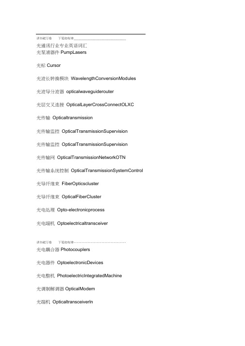
读书破万卷下笔如有神__________________________________光通讯行业专业英语词汇光泵浦器件PumpLasers光标Cursor光波长转换模块WavelengthConversionModules光波导分波器opticalwaveguiderouter光层交叉连接OpticalLayerCrossConnectOLXC光传输Opticaltransmission光传输监控OpticalTransmissionSupervision光传输监控OpticalTransmissionSupervision光传输网OpticalTransmissionNetworkOTN光传输系统控制OpticalTransmissionSystemControl 光导纤维束FiberOpticscluster光导纤维束OpticalFiberCluster光电处理Opto-electronicprocess光电端机Optoelectricaltransceiver读书破万卷下笔如有神----------------------------------光电耦合器Photocouplers光电器件OptoelectronicDevices光电整机PhotoelectricIntegratedMachine光调制解调器OpticalModem光端机Opticaltransceiverln光多用表OpticalMultimeter 光发射单元OpticalTransmitUnitOlU光发射二级管LightEmittingDiodeLED 光发送二极管OpticalTransmittingLEDs 光发送模块OpitcalTransmitters 光发送器件OpticalTransmittingComponents 光放大器OpticalAmplifierOA 光分波单元OpticaldemultiplexingunitODU 光分波器OpticalDemultiplexerUnitODU 光分插复用器OpticalAdd/DropMultiplexerOADM读书破万卷下笔如有神_________________________________光分路器OpticalDivider光分配点OpticalDistributionPointODP 光分配节点OpticalDistributionNodeODN 光分配网络OpticalDistributionNetworkODN 光分支装置OpticalBranchingDeviceOBD 光复用器OpticalMultiplexer 光告警方式OpticalAlarmingMode 光隔离器Opticallsolator光功率差OpticalPowerDifferenee光功率计OpticalPowerMeter光合波板OpticalMultiplexerUnitOMU光交叉连接光互联OpticalCross—connectOXCu o o a)u u e l p _e o l d o affl 来」or ①a)p o o u d 幣w K g l f瑟. 吕w p① o e 七①l£lndu一-eoldo4ouole匸①PAOU①nb①」4p ①左lu」① d s ^^y 口 <«狽s」①>eosue匚不。
光纤通信技术外文翻译中英对照
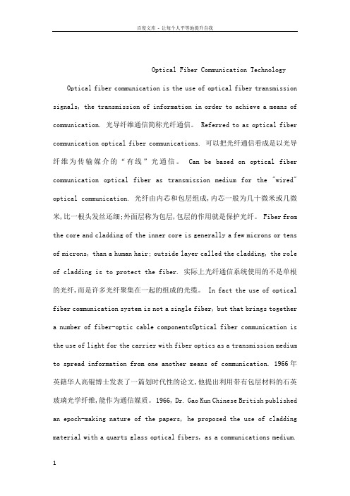
Optical Fiber Communication TechnologyOptical fiber communication is the use of optical fiber transmission signals, the transmission of information in order to achieve a means of communication. 光导纤维通信简称光纤通信。
Referred to as optical fiber communication optical fiber communications. 可以把光纤通信看成是以光导纤维为传输媒介的“有线”光通信。
Can be based on optical fiber communication optical fiber as transmission medium for the "wired" optical communication. 光纤由内芯和包层组成,内芯一般为几十微米或几微米,比一根头发丝还细;外面层称为包层,包层的作用就是保护光纤。
Fiber from the core and cladding of the inner core is generally a few microns or tens of microns, than a human hair; outside layer called the cladding, the role of cladding is to protect the fiber. 实际上光纤通信系统使用的不是单根的光纤,而是许多光纤聚集在一起的组成的光缆。
In fact the use of optical fiber communication system is not a single fiber, but that brings together a number of fiber-optic cable componentsOptical fiber communication is the use of light for the carrier with fiber optics as a transmission medium to spread information from one another means of communication. 1966年英籍华人高锟博士发表了一篇划时代性的论文,他提出利用带有包层材料的石英玻璃光学纤维,能作为通信媒质。
光纤通信(Optical Fiber Communication)Optical Amplifiers PPT课件

The Sch. Of Information Engineering, WHUT
CONTENT
11.1.3 Amplifier noise
Optical amplifiers introduce noise and degrade SNR. Source of noise: Spontaneous emission Noise spectral density
P is the optical power of the signal being amplified
Ps is the saturation power
2016/3/7 The Sch. Of Information Engineering, WHUT 5
CONTENT
In the unsaturated regime P Ps 1
2016/3/7
The Sch. Of Information Engineering, WHUT
18
CONTENT
11.2.3 Problems with SOAs
2016/3/7
The Sch. Of Information Engineering, WHUTLeabharlann 19CONTENT
SOA provide Polarization dependent gain: several schemes can solve this problem partially.
15
CONTENT
2016/3/7
The Sch. Of Information Engineering, WHUT
16
CONTENT
11.2.2 Amplifier characteristics
光纤通信(Optical Fiber Communication)Optical FiberPPT课件

tan
2
2E0x E0y cos
E02x E02y
2020/7/24
The Sch. Of Information Engineering, WHUT
14
CONTENT
2020/7/24
The Sch. Of Information Engineering, WHUT
15
CONTENT
When E0x E0 y E0 , 2 2m (m 0, 1, 2 )
CONTENT
Chapter2 Optical Fiber
2020/7/24
The Sch. Of Information Engineering, WHUT
1
OUTLINE
CONTENT
The nature of light The fabrication of optical fibers The structure of an optical fiber The propagation principle of light along a fiber The transmission character of fiber
CONTENT
In 1815, Fresnel gived the correct explanation of diffraction. In 1864, Maxwell theorized that light waves must be electromagnetic in nature. The observation of polarization effects indicated that light wave are transverse. It is no different from a radio wave except that the wavelength is much shorter.
OpticalCommunications光通信-文档资料
Applications
Transmit telephone signals
Transmit Internet communication Transmit cable television signals
Free-space optical communication
Free-space:air,outer space,vacuum,or something similar
Optical Detectors
Avalanche Photodetector (APD) Better sensitivity than PIN detector Temperature sensitive Data rate to 2.5Gbps P-I-D Photodiode: Wideband 800 - 1600 nm High data rate up to 100Gbps
Optical fiber communication
during 1970s,the development of extremely low-loss optical fibers Transmit information from one place to another by sending pulses of light through an optical fiber
Optical Communications
Members: Xiaoyu Zhao Chenjiao Bai Fanfan Lian Qiaoli Xu Jun Liu Yao Xu Jun Hu
Overview
Definition Technology
Optical transmitters/sources Optical receivers/detectors
光通信英语作文
光通信英语作文Optical communication has revolutionized the way we transmit and receive information in the modern world. This technology, which utilizes light as the medium for data transmission, has become the backbone of global communication networks, enabling the seamless exchange of information across vast distances at unprecedented speeds. In this essay, we will explore the fundamental principles of optical communication, its evolution, and its pivotal role in shaping the digital landscape of the 21st century.At the core of optical communication is the use of light as the carrier of information. Light, a form of electromagnetic radiation, can be modulated to encode digital data, which can then be transmitted through various mediums such as optical fibers or free-space. The ability to harness the properties of light, including its high frequency, directionality, and low attenuation, has made optical communication a superior choice over traditional electrical communication systems.The history of optical communication can be traced back to the late 19th century, when the first experiments with light-basedcommunication were conducted. The invention of the laser in the 1960s, however, marked a significant turning point, as it provided a reliable and coherent light source that could be effectively modulated and transmitted over long distances. The development of low-loss optical fibers, which can guide light with minimal signal degradation, further propelled the growth of optical communication in the 1970s and 1980s.Today, optical communication systems are ubiquitous, underpinning a vast array of applications and technologies. In the telecommunications industry, optical fiber networks form the backbone of global communication infrastructure, enabling the transmission of voice, data, and video at unprecedented speeds. These fiber-optic networks have revolutionized the way we communicate, allowing for the seamless exchange of information across continents and oceans.Beyond telecommunications, optical communication has found widespread applications in various fields. In the field of data centers and cloud computing, optical interconnects are used to link servers and storage systems, providing the high-speed data transfer required to support the growing demand for computational resources. In the healthcare sector, optical communication techniques are employed in medical imaging and diagnostic equipment, enabling the capture and transmission of high-resolutionimages and data.The advent of fiber-optic sensors has also opened up new frontiers in fields such as structural health monitoring, environmental sensing, and industrial automation. These sensors, which utilize light-based detection mechanisms, can measure a wide range of physical, chemical, and environmental parameters with high precision and reliability.The advantages of optical communication extend beyond its raw speed and capacity. Optical signals are also inherently more secure than their electrical counterparts, as they are less susceptible to electromagnetic interference and eavesdropping. This makes optical communication an attractive choice for applications where data privacy and security are of paramount importance, such as in government, military, and financial sectors.Moreover, optical communication systems have a significantly lower energy footprint compared to traditional electrical communication systems. The use of light as the carrier of information, combined with the high efficiency of optical components, has led to a substantial reduction in power consumption and carbon emissions, making optical communication a more sustainable and environmentally friendly solution.As we look to the future, the potential of optical communication continues to expand. The development of advanced optical technologies, such as wavelength-division multiplexing, coherent detection, and all-optical signal processing, has enabled even greater bandwidth and capacity. The integration of optical communication with emerging technologies, such as 5G, the Internet of Things (IoT), and quantum computing, promises to unlock new frontiers of communication and information processing.Furthermore, the ongoing research and development in areas like free-space optical communication, where data is transmitted through the atmosphere using laser beams, hold the promise of revolutionizing communication in scenarios where traditional wired or wireless solutions are impractical or unavailable, such as in space exploration, disaster response, and remote areas.In conclusion, optical communication has transformed the way we transmit and receive information, becoming the foundation of modern global communication networks. Its ability to harness the properties of light has enabled unprecedented speeds, capacity, and energy efficiency, making it an indispensable technology in the digital age. As we continue to push the boundaries of optical communication, we can expect to see even more remarkable advancements that will shape the future of communication and information technology.。
光纤通信技术 英文教材

光纤通信技术英文教材English:Fiber optic communication technology is a method of transmitting information from one place to another by sending pulses of light through an optical fiber. This technology provides high-speed data transmission and is widely used in telecommunications, internet, and networking. The core of a fiber optic cable is made of a very thin strand of glass or plastic that is capable of transmitting light waves over long distances with minimal loss of signal strength. The information is encoded into the light pulses and then decoded at the receiving end, allowing for secure and reliable communication. Compared to traditional copper wire communication, fiber optic technology offers higher bandwidth, greater resistance to electromagnetic interference, and increased security due to the difficulty of tapping into the signal without detection.中文翻译:光纤通信技术是一种通过光纤发送光脉冲来实现信息在不同地点之间传输的方法。
光通信产品介绍英语作文

Optical Communication Products:Revolutionizing the Way We ConnectIn today's world, the backbone of our digital societyis the rapid and reliable transmission of data. Optical communication products, at the forefront of this revolution, have transformed the way we connect, communicate, and share information. These cutting-edge devices utilize the speed and bandwidth of light to enable seamless connectivity across vast distances, revolutionizing the telecommunications industry.Optical fibers, the core component of optical communication systems, are thin strands of glass or plastic capable of carrying information as light pulses. Thesefibers are capable of transmitting data at speeds far surpassing traditional copper cables, with the potential to carry multiple signals simultaneously. This high bandwidth capacity allows for the seamless transmission of voice, video, and data traffic, essential for today's connected world.Optical communication products also boast exceptional reliability. The durability of optical fibers and theirresistance to electromagnetic interference makes them ideal for use in a wide range of environments, from dense urban areas to remote locations. This reliability ensures that critical infrastructure such as healthcare, finance, and government services can rely on consistent and secure connectivity.Moreover, optical communication products are highly scalable. As demand for bandwidth continues to grow,optical systems can be easily upgraded to meet these demands. This scalability ensures that optical communication solutions can adapt to the evolving needs of modern society, supporting the continued growth and development of our digital world.In addition to their speed, reliability, and scalability, optical communication products also offer environmental benefits. Their efficient use of energy and reduced carbon emissions compared to traditional copper cables makes them a sustainable choice for the telecommunications industry. As we face the challenges of climate change, the adoption of optical communicationproducts is crucial for reducing the environmental impactof our digital infrastructure.In conclusion, optical communication products are essential for powering our connected world. Their speed, reliability, scalability, and environmental sustainability have revolutionized the telecommunications industry, enabling seamless connectivity and communication across the globe. As we look towards the future, optical communication products will continue to play a pivotal role in shapingthe way we connect, communicate, and share information.**光通信产品:重塑我们的连接方式**在当今社会,我们数字社会的支柱是快速而可靠的数据传输。
光纤通信英文介绍

Fiber-Optic CommunicationOverviewFiber-optic communication is a method of transmitting information from one place to another by sending pulses of light through an optical fiber. The light forms an electromagnetic carrier wave that is modulated to carry information. First developed in the 1970s, fiber-optic communication systems have revolutionized the telecommunications industry and have played a major role in the advent of the Information Age. Because of its advantages over electrical transmission, optical fibers have largely replaced copper wire communications in core networks in the developed world.The process of communicating using fiber-optics involves the following basic steps: Creating the optical signal involving the use of a transmitter, relaying the signal along the fiber, ensuring that the signal does not become too distorted or weak, receiving the optical signal, and converting it into an electrical signal.ApplicationsOptical fiber is used by many telecommunications companies to transmit telephone signals, Internet communication, and cable television signals. Due to much lower attenuation and interference, optical fiber has large advantages over existing copper wire in long-distance and high-demand applications. However, infrastructure development within cities was relatively difficult and time-consuming, and fiber-optic systems were complex and expensive to install and operate. Due to these difficulties, fiber-optic communication systems have primarily been installed in long-distance applications, where they can be used to their full transmission capacity, offsetting the increased cost. Since 2000, the prices for fiber-optic communications have dropped considerably. The price for rolling out fiber to the home has currently become more cost-effective than that of rolling out a copper based network. Prices have dropped to $850 per subscriber in the US and lower in countries like The Netherlands, where digging costs are low.Since 1990, when optical-amplification systems became commercially available, the telecommunications industry has laid a vast network of intercity and transoceanic fiber communication lines. By 2002, an intercontinental network of 250,000 km of submarine communications cable with a capacity of 2.56 Tb/s was completed, and although specific network capacities are privileged information, telecommunications investment reports indicate that network capacity has increased dramatically since 2004.HistoryIn 1880 Alexander Graham Bell and his assistant Charles Sumner Tainter created a very early precursor to fiber-optic communications, the Photophone, at Bell's newly established Volta Laboratory in Washington, D.C. Bell considered it his most important invention. The device allowed for the transmission of sound on a beam of light. On June 3, 1880, Bell conducted the world's first wireless telephone transmission between two buildings, some 213 meters apart. Due to its use of an atmospheric transmission medium, the Photophone would not prove practical until advances in laser and optical fiber technologies permitted the secure transport of light. ThePhotophone's first practical use came in military communication systems many decades later.In 1966 Charles K. Kao and George Hockham proposed optical fibers at STC Laboratories (STL) at Harlow, England, when they showed that the losses of 1000 dB/km in existing glass (compared to 5-10 dB/km in coaxial cable) was due to contaminants, which could potentially be removed. Optical fiber was successfully developed in 1970 by Corning Glass Works, with attenuation low enough for communication purposes (about 20dB/km), and at the same time GaAs semiconductor lasers were developed that were compact and therefore suitable for transmitting light through fiber optic cables for long distances.After a period of research starting from 1975, the first commercial fiber-optic communications system was developed, which operated at a wavelength around 0.8 µm and used GaAs semiconductor lasers. This first-generation system operated at a bit rate of 45 Mbps with repeater spacing of up to 10 km. Soon on 22 April 1977, General Telephone and Electronics sent the first live telephone traffic through fiber optics at a 6 Mbit/s throughput in Long Beach, California.The second generation of fiber-optic communication was developed for commercial use in the early 1980s, operated at 1.3 µm, and used InGaAsP semiconductor lasers. These early systems were initially limited by multi mode fiber dispersion, and in 1981 the single-mode fiber was revealed to greatly improve system performance, however practical connectors capable of working with single mode fiber proved difficult to develop. By 1987, these systems were operating at bit rates of up to 1.7 Gb/s with repeater spacing up to 50 km.The first transatlantic telephone cable to use optical fiber was TAT-8, based on Desurvire optimized laser amplification technology. It went into operation in 1988.Third-generation fiber-optic systems operated at 1.55 µm and had losses of about 0.2 dB/km. They achieved this despite earlier difficulties with pulse-spreading at that wavelength using conventional InGaAsP semiconductor lasers. Scientists overcame this difficulty by using dispersion-shifted fibers designed to have minimal dispersion at 1.55 µm or by limiting the laser spectrum to a single longitudinal mode. These developments eventually allowed third-generation systems to operate commercially at 2.5 Gbit/s with repeater spacing in excess of 100 km.The fourth generation of fiber-optic communication systems used optical amplification to reduce the need for repeaters and wavelength-division multiplexing to increase data capacity. These two improvements caused a revolution that resulted in the doubling of system capacity every 6 months starting in 1992 until a bit rate of 10 Tb/s was reached by 2001. In 2006 a bit-rate of 14 Tbit/s was reached over a single 160 km line using optical amplifiers.The focus of development for the fifth generation of fiber-optic communications is on extending the wavelength range over which a WDM system can operate. The conventional wavelength window, known as the C band, covers the wavelength range 1.53-1.57 µm, and dry fiber has a low-loss window promising an extension of that range to 1.30-1.65 µm. Other developments include the concept of "optical solitons, " pulses that preserve their shape by counteracting the effects of dispersion with the nonlinear effects of the fiber by using pulses of a specific shape.In the late 1990s through 2000, industry promoters, and research companies such as KMI, and RHK predicted massive increases in demand for communications bandwidth due to increased use of the Internet, and commercialization of various bandwidth-intensive consumer services, such as video on demand. Internet protocol data traffic was increasing exponentially, at a faster rate thanintegrated circuit complexity had increased under Moore's Law. From the bust of the dot-com bubble through 2006, however, the main trend in the industry has been consolidation of firms and offshoring of manufacturing to reduce costs. Companies such as Verizon and AT&T have taken advantage of fiber-optic communications to deliver a variety of high-throughput data and broadband services to consumers' homes.TechnologyModern fiber-optic communication systems generally include an optical transmitter to convert an electrical signal into an optical signal to send into the optical fiber, a cable containing bundles of multiple optical fibers that is routed through underground conduits and buildings, multiple kinds of amplifiers, and an optical receiver to recover the signal as an electrical signal. The information transmitted is typically digital information generated by computers, telephone systems, and cable television companies.TransmittersA GBIC module (shown here with its cover removed), isan optical and electrical transceiver. The electricalconnector is at top right, and the optical connectors areat bottom leftThe most commonly-used optical transmitters aresemiconductor devices such as light-emitting diodes(LEDs) and laser diodes. The difference between LEDsand laser diodes is that LEDs produce incoherent light,while laser diodes produce coherent light. For use in optical communications, semiconductor optical transmitters must be designed to be compact, efficient, and reliable, while operating in an optimal wavelength range, and directly modulated at high frequencies.In its simplest form, an LED is a forward-biased p-n junction, emitting light through spontaneous emission, a phenomenon referred to as electroluminescence. The emitted light is incoherent with a relatively wide spectral width of 30-60 nm. LED light transmission is also inefficient, with only about 1 % of input power, or about 100 microwatts, eventually converted into launched power which has been coupled into the optical fiber. However, due to their relatively simple design, LEDs are very useful for low-cost applications.Communications LEDs are most commonly made from gallium arsenide phosphide (GaAsP) or gallium arsenide (GaAs). Because GaAsP LEDs operate at a longer wavelength than GaAs LEDs (1.3 micrometers vs. 0.81-0.87 micrometers), their output spectrum is wider by a factor of about 1.7. The large spectrum width of LEDs causes higher fiber dispersion, considerably limiting their bit rate-distance product (a common measure of usefulness). LEDs are suitable primarily for local-area-network applications with bit rates of 10-100 Mbit/s and transmission distances of a few kilometers. LEDs have also been developed that use several quantum wells to emit light at different wavelengths over a broad spectrum, and are currently in use for local-area WDM networks.Today, LEDs have been largely superseded by VCSEL (Vertical Cavity Surface Emitting Laser)devices, which offer improved speed, power and spectral properties, at a similar cost. CommonVCSEL devices couple well to multi mode fiber.A semiconductor laser emits light through stimulated emission rather than spontaneous emission, which results in high output power (~100 mW) as well as other benefits related to the nature of coherent light. The output of a laser is relatively directional, allowing high coupling efficiency (~50 %) into single-mode fiber. The narrow spectral width also allows for high bit rates since it reduces the effect of chromatic dispersion. Furthermore, semiconductor lasers can be modulated directly at high frequencies because of short recombination time.Commonly used classes of semiconductor laser transmitters used in fiber optics include VCSEL (Vertical Cavity Surface Emitting Laser), Fabry–Pérot and DFB (Distributed Feed Back).Laser diodes are often directly modulated, that is the light output is controlled by a current applied directly to the device. For very high data rates or very long distance links, a laser source may be operated continuous wave, and the light modulated by an external device such as an electro-absorption modulator or Mach–Zehnder interferometer. External modulation increases the achievable link distance by eliminating laser chirp, which broadens the linewidth of directly-modulated lasers, increasing the chromatic dispersion in the fiber.[edit] ReceiversThe main component of an optical receiver is a photodetector, which converts light into electricity using the photoelectric effect. The photodetector is typically a semiconductor-based photodiode. Several types of photodiodes include p-n photodiodes, a p-i-n photodiodes, and avalanche photodiodes. Metal-semiconductor-metal (MSM) photodetectors are also used due to their suitability for circuit integration in regenerators and wavelength-division multiplexers. Optical-electrical converters are typically coupled with a transimpedance amplifier and a limiting amplifier to produce a digital signal in the electrical domain from the incoming optical signal, which may be attenuated and distorted while passing through the channel. Further signal processing such as clock recovery from data (CDR) performed by a phase-locked loop may also be applied before the data is passed on.FiberA cable reel trailer with conduit that can carry optical fiber.Single-mode optical fiber in an underground service pitMain articles: Optical fiber and Optical fiber cableAn optical fiber consists of a core, cladding, and a buffer (a protective outer coating), in which thecladding guides the light along the core by using the method of total internal reflection. The coreand the cladding (which has a lower-refractive-index) are usually made of high-quality silica glass, although they can both be made of plastic as well. Connecting two optical fibers is done by fusion splicing or mechanical splicing and requires special skills and interconnection technology due to the microscopic precision required to align the fiber cores.Two main types of optical fiber used in optic communications include multi-mode optical fibers and single-mode optical fibers. A multi-mode optical fiber has a larger core (≥50 micrometres), allowing less precise, cheaper transmitters and receivers to connect to it as well as cheaper connectors. However, a multi-mode fiber introduces multimode distortion, which often limits the bandwidth and length of the link. Furthermore, because of its higher dopant content, multi-mode fibers are usually expensive and exhibit higher attenuation. The core of a single-mode fiber is smaller (<10 micrometres) and requires more expensive components and interconnection methods, but allows much longer, higher-performance links.In order to package fiber into a commercially-viable product, it is typically protectively-coated by using ultraviolet (UV), light-cured acrylate polymers, then terminated with optical fiber connectors, and finally assembled into a cable. After that, it can be laid in the ground and then run through the walls of a building and deployed aerially in a manner similar to copper cables. These fibers require less maintenance than common twisted pair wires, once they are deployed.AmplifiersThe transmission distance of a fiber-optic communication system has traditionally been limited by fiber attenuation and by fiber distortion. By using opto-electronic repeaters, these problems have been eliminated. These repeaters convert the signal into an electrical signal, and then use a transmitter to send the signal again at a higher intensity than it was before. Because of the high complexity with modern wavelength-division multiplexed signals (including the fact that they had to be installed about once every 20 km), the cost of these repeaters is very high.An alternative approach is to use an optical amplifier, which amplifies the optical signal directly without having to convert the signal into the electrical domain. It is made by doping a length of fiber with the rare-earth mineral erbium, and pumping it with light from a laser with a shorter wavelength than the communications signal (typically 980 nm). Amplifiers have largely replaced repeaters in new installations.Wavelength-division multiplexingWavelength-division multiplexing (WDM) is the practice of multiplying the available capacity of an optical fiber by adding new channels, each channel on a new wavelength of light. This requires a wavelength division multiplexer in the transmitting equipment and a demultiplexer (essentially a spectrometer) in the receiving equipment. Arrayed waveguide gratings are commonly used for multiplexing and demultiplexing in WDM. Using WDM technology now commercially available, the bandwidth of a fiber can be divided into as many as 160 channels to support a combined bit rate into the range of terabits per second.Bandwidth-distance productBecause the effect of dispersion increases with the length of the fiber, a fiber transmission system is often characterized by its bandwidth-distance product, usually expressed in units of MHz×km.This value is a product of bandwidth and distance because there is a trade off between the bandwidth of the signal and the distance it can be carried. For example, a common multi-mode fiber with bandwidth-distance product of 500 MHz×km could carry a 500 MHz signal for 1 km or a 1000 MHz signal for 0.5 km.Engineers are always looking at current limitations in order to improve fiber-optic communication, and several of these restrictions are currently being researched. Each fiber can carry many independent channels, each using a different wavelength of light (wavelength-division multiplexing (WDM)). The net data rate (data rate without overhead bytes) per fiber is the per-channel data rate reduced by the FEC overhead, multiplied by the number of channels (usually up to eighty in commercial dense WDM systems as of 2008). For instance, NTT was able to achieve 69.1 Tbit/s transmission by applying wavelength division multiplex (WDM) of 432 wavelengths with a capacity of 171 Gbit/s over a single 240 km-long optical fiber on March 25, 2010. This was the highest optical transmission speed recorded at that time.DispersionFor modern glass optical fiber, the maximum transmission distance is limited not by direct material absorption but by several types of dispersion, or spreading of optical pulses as they travel along the fiber. Dispersion in optical fibers is caused by a variety of factors. Intermodal dispersion, caused by the different axial speeds of different transverse modes, limits the performance of multi-mode fiber. Because single-mode fiber supports only one transverse mode, intermodal dispersion is eliminated.In single-mode fiber performance is primarily limited by chromatic dispersion (also called group velocity dispersion), which occurs because the index of the glass varies slightly depending on the wavelength of the light, and light from real optical transmitters necessarily has nonzero spectral width (due to modulation). Polarization mode dispersion, another source of limitation, occurs because although the single-mode fiber can sustain only one transverse mode, it can carry this mode with two different polarizations, and slight imperfections or distortions in a fiber can alter the propagation velocities for the two polarizations. This phenomenon is called fiber birefringence and can be counteracted by polarization-maintaining optical fiber. Dispersion limits the bandwidth of the fiber because the spreading optical pulse limits the rate that pulses can follow one another on the fiber and still be distinguishable at the receiver.Some dispersion, notably chromatic dispersion, can be removed by a 'dispersion compensator'. This works by using a specially prepared length of fiber that has the opposite dispersion to that induced by the transmission fiber, and this sharpens the pulse so that it can be correctly decoded by the electronics.AttenuationFiber attenuation, which necessitates the use of amplification systems, is caused by a combination of material absorption, Rayleigh scattering, Mie scattering, and connection losses. Although material absorption for pure silica is only around 0.03 dB/km (modern fiber has attenuation around 0.3 dB/km), impurities in the original optical fibers caused attenuation of about 1000 dB/km. Other forms of attenuation are caused by physical stresses to the fiber, microscopic fluctuations in density, and imperfect splicing techniques.Transmission windowsEach effect that contributes to attenuation and dispersion depends on the optical wavelength. The wavelength bands (or windows) that exist where these effects are weakest are the most favorable for transmission. These windows have been standardized, and the currently defined bands are the following:Band Description Wavelength RangeO band original 1260 to 1360 nmE band extended 1360 to 1460 nmS band short wavelengths 1460 to 1530 nmC band conventional ("erbium window") 1530 to 1565 nmL band long wavelengths 1565 to 1625 nmU band ultralong wavelengths 1625 to 1675 nmNote that this table shows that current technology has managed to bridge the second and third windows that were originally disjoint.Historically, there was a window used below the O band, called the first window, at 800-900 nm; however, losses are high in this region so this window is used primarily for short-distance communications. The current lower windows (O and E) around 1300 nm have much lower losses. This region has zero dispersion. The middle windows (S and C) around 1500 nm are the most widely used. This region has the lowest attenuation losses and achieves the longest range. It does have some dispersion, so dispersion compensator devices are used to remove this.RegenerationWhen a communications link must span a larger distance than existing fiber-optic technology is capable of, the signal must be regenerated at intermediate points in the link by repeaters. Repeaters add substantial cost to a communication system, and so system designers attempt to minimize their use.Recent advances in fiber and optical communications technology have reduced signal degradation so far that regeneration of the optical signal is only needed over distances of hundreds of kilometers. This has greatly reduced the cost of optical networking, particularly over undersea spans where the cost and reliability of repeaters is one of the key factors determining the performance of the whole cable system. The main advances contributing to these performance improvements are dispersion management, which seeks to balance the effects of dispersion against non-linearity; and solitons, which use nonlinear effects in the fiber to enable dispersion-free propagation over long distances.Last mileAlthough fiber-optic systems excel in high-bandwidth applications, optical fiber has been slow to achieve its goal of fiber to the premises or to solve the last mile problem. However, as bandwidth demand increases, more and more progress towards this goal can be observed. In Japan, for instance EPON has largely replaced DSL as a broadband Internet source. South Korea’s KT also provides a service called FTTH (Fiber To The Home), which provides fiber-optic connections to thesubscriber’s home. Th e largest FTTH deployments are in Japan, Korea, and China. Singapore started implementation of their all-fibre Next Generation Nationwide Broadband Network (Next Gen NBN), which is slated for completion in 2012 and is being installed by OpenNet. Since they began rolling out services in September 2010, Network coverage in Singapore has reached 60% nationwide.In the US, Verizon Communications provides a FTTH service called FiOS to select high-ARPU (Average Revenue Per User) markets within its existing territory. The other major surviving ILEC (or Incumbent Local Exchange Carrier), AT&T, uses a FTTN (Fiber To The Node) service called U-verse with twisted-pair to the home. Their MSO competitors employ FTTN with coax using HFC. All of the major access networks use fiber for the bulk of the distance from the service provider's network to the customer.The globally dominant access network technology is EPON (Ethernet Passive Optical Network). In Europe, and among telcos in the United States, BPON (ATM-based Broadband PON) and GPON (Gigabit PON) had roots in the FSAN (Full Service Access Network) and ITU-T standards organizations under their control.Comparison with electrical transmissionA mobile fiber optic splice lab used to access and splice underground cables.An underground fiber optic splice enclosure opened up.The choice between optical fiber and electrical (or copper) transmission for a particular system is made based on a number of trade-offs. Optical fiber is generally chosen for systems requiring higher bandwidth or spanning longer distances than electrical cabling can accommodate.The main benefits of fiber are its exceptionally low loss (allowing long distances between amplifiers/repeaters), its absence of ground currents and other parasite signal and power issues common to long parallel electric conductor runs (due to its reliance on light rather than electricity for transmission, and the dielectric nature of fiber optic), and its inherently highdata-carrying capacity. Thousands of electrical links would be required to replace a single high bandwidth fiber cable. Another benefit of fibers is that even when run alongside each other for long distances, fiber cables experience effectively no crosstalk, in contrast to some types of electrical transmission lines. Fiber can be installed in areas with high electromagnetic interference (EMI), such as alongside utility lines, power lines, and railroad tracks. Nonmetallic all-dielectric cables are also ideal for areas of high lightning-strike incidence.For comparison, while single-line, voice-grade copper systems longer than a couple of kilometers require in-line signal repeaters for satisfactory performance; it is not unusual for optical systems to go over 100 kilometers (60 miles), with no active or passive processing. Single-mode fiber cables are commonly available in 12 km lengths, minimizing the number of splices required over a long cable run. Multi-mode fiber is available in lengths up to 4 km, although industrial standards only mandate 2 km unbroken runs.In short distance and relatively low bandwidth applications, electrical transmission is often preferred because of its∙Lower material cost, where large quantities are not required∙Lower cost of transmitters and receivers∙Capability to carry electrical power as well as signals (in specially-designed cables)∙Ease of operating transducers in linear mode.Optical fibers are more difficult and e xpensive to splice than electrical conductors. And at higher powers, optical fibers are susceptible to fiber fuse, resulting in catastrophic destruction of the fiber core and damage to transmission components.Because of these benefits of electrical transmission, optical communication is not common in short box-to-box, backplane, or chip-to-chip applications; however, optical systems on those scales have been demonstrated in the laboratory.In certain situations fiber may be used even for short distance or low bandwidth applications, due to other important features:∙Immunity to electromagnetic interference, including nuclear electromagnetic pulses (although fiber can be damaged by alpha and beta radiation).∙High electrical resistance, making it safe to use near high-voltage equipment or between areas with different earth potentials.∙Lighter weight—important, for example, in aircraft.∙No sparks—important in flammable or explosive gas environments.∙Not electromagnetically radiating, and difficult to tap without disrupting the signal—important in high-security environments.∙Much smaller cable size—important where pathway is limited, such as networking an existing building, where smaller channels can be drilled and space can be saved in existing cable ducts and trays.Optical fiber cables can be installed in buildings with the same equipment that is used to install copper and coaxial cables, with some modifications due to the small size and limited pull tension and bend radius of optical cables. Optical cables can typically be installed in duct systems in spans of 6000 meters or more depending on the duct's condition, layout of the duct system, and installation technique. Longer cables can be coiled at an intermediate point and pulled farther into the duct system as necessary(Remark: Above information is derived from , as reference only)。
1 introduction 光纤通信英文版 介绍
光 纤 通 信
光纤通信
• • • • • • • •
resistor 电阻; capacitor 电容; inductor 电感; information-carrying capacity 信息承载容量; pulse-code modulation (PCM) 脉冲编码调制; acoustic signal 声学(声音)信号; binary 二进制; miniature semiconductor 微型半导体
光纤通信
• 本课程对学生提出以下要求: • (1)掌握光纤和光缆的结构和类型、光纤的传输 原理和特性、光纤特性的测量; • (2)掌握光纤通信系统各组成部分包括光源、光 端机、光检测器、接收机、光无源器件的结构和 工作原理; • (3)熟悉光纤通信新技术和新系统的研究发展情 况; • (4)熟悉光缆敷设施工的过程以及光纤光缆特性 测试和故障检修; • (5)能计算光纤工程中所需的基本参数,能将所光 学知识与工程实践相结合; 纤
信
光纤通信
频率 波长 名称 紫外线 可见光线 (光纤通信用) 近红外线 远红外线 亚毫米波 1m m 10 m m 1 00 m m 1m 1 0m 1 00m 毫米波 (EHF) 厘米波 (SHF) 分米波 (UHF) 米波(VHF) 短波(HF) 中波(MF)
光纤通信
• The Shannon-Hartley theorem can answer the Shanon • question above: limit
• C=BW×log2(1+SNR)
• Where C is the information-carrying capacity, BW is the link bandwidth, and SNR is the signal-noise power ratio. • The Shannon theorem states that information carrying capacity is proportional to channel bandwidth, the range 光 纤 of frequencies within which the signals can be transmitted 通 信 without substantial attenuation.
光纤通信简介专业英语要点
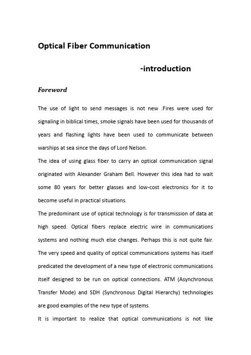
Optical Fiber Communication-introduction ForewordThe use of light to send messages is not new .Fires were used for signaling in biblical times, smoke signals have been used for thousands of years and flashing lights have been used to communicate between warships at sea since the days of Lord Nelson.The idea of using glass fiber to carry an optical communication signal originated with Alexander Graham Bell. However this idea had to wait some 80 years for better glasses and low-cost electronics for it to become useful in practical situations.The predominant use of optical technology is for transmission of data at high speed. Optical fibers replace electric wire in communications systems and nothing much else changes. Perhaps this is not quite fair. The very speed and quality of optical communications systems has itself predicated the development of a new type of electronic communications itself designed to be run on optical connections. ATM (Asynchronous Transfer Mode) and SDH (Synchronous Digital Hierarchy) technologies are good examples of the new type of systems.It is important to realize that optical communications is not likeelectronic communications. While it seems that light travels in a fiber much like electricity does in a wire this is very misleading. Light is an electromagnetic wave and optical fiber is a waveguide. Everything to do with transport of the signal even to simple things like coupling (joining) two fibers into one is very different from what happens in the electronic world. The two fields (electronics and optics) while closely related employ different principles in different ways.Some people look ahead to “true”optical networks. These will be networks where routing is done optically from one end-user to another without the signal ever becoming electronic. Indeed some experimental local area (LAN) and metropolitan area (MAN) networks like this have been built. In 1998 optically routed nodal wide area networks are imminently feasible and the necessary components to build them are available. However, no such networks have been deployed operationally yet.In 1998 the “happening”area in optical communications was Wavelength Division Multiplexing (WDM). This is the ability to send many (perhaps up to 1000) independent optical channels on a single fiber. The first fully commercial WDM products appeared on the market in 1996. WDM is a major step toward fully optical networking.1. Transmitting Light on a FiberAn optical fiber is a very thin strand of silica glass in geometry quite like a human hair. In reality it is a very narrow, very long glass cylinder with special characteristics. When light enters one end of the fiber, it travels (confined within the fiber) until it leaves the fiber at the other end. Two critical factors stand out:Very little light is lost in its journey along the fiber.Fiber can bend around corners and the light will stay within it and be guided around the corners.An optical fiber consists of two parts: the core and the cladding. The core is a narrow cylindrical strand of glass and the cladding is a tubular jacket surrounding it. The core has a (slightly) higher refractive index than the cladding. This means that the boundary (interface) between the core and the cladding acts as a perfect mirror. Light traveling along the core is confined by the mirror to stay within it-even when the fiber bends around a corner.When light is transmitted on a fiber, the most important consideration is “what kind of light?”The electromagnetic radiation that we call light exists at many wavelengths. These wavelengths go from invisible infrared through all the colours of the visible spectrum to invisible ultraviolet. Because of the attenuation characteristics of fiber, we are only interested in infrared “light”for communication applications. This light is usuallyinvisible, since the wavelengths used are usually longer than the visible limit of around 750 nanometers ( nm ) .If a short pulse of light from a source such as a laser or an LED is sent down a narrow fiber, it will be changed (degraded) by its passage down the fiber. It will emerge (depending on the distance) much weaker, lengthened in time (“smeared out”), and distorted in other ways.2. Optical Transmission System ConceptsThe basic components of an optical communication system are optical transmitter and receiver,Fiber jumpers,Optical,fiber splice tray Optical fiber.A serial bit stream in electrical from is presented to a modulator, which encodes the data appropriately for fiber transmission.A light source (laser or Light Emitting Diode—LED) is driven by the modulator and the light focused into the fiber. The light travels down the fiber (during which time it may experience dispersion and loss of strength).At the receiver end the light is fed to a detector and converted to electrical form. The signal is then amplified and fed to another detector, which isolates the individual state changes and their timing. It then decodes the sequence of state changes and reconstructs the original bit stream.The timed bit stream so received may then be fed to a using device. Optical communication has many well-known advantages.Weight and SizeFiber cable is significantly smaller and lighter than electrical cables to do the same job. In the wide area environment a large coaxial cable system can easily involve a cable of several inches in diameter and weighing many pounds per foot. A fiber cable to do the same job could be less than one half an inch in diameter and weigh a few ounces per foot. This means that the cost of laying the cable is dramatically reduced. Material CostFiber cable costs significantly less than copper cable for the same transmission capacity.Information CapacityThe idea rate of system in 1998 was generally 150 or 620Mbps on a single (unidirectional) fiber. This is because these systems were installed in past years. The usual rate for new systems is 2.4Gbps or even 10Gbps. This is very high in digital transmission terms.In telephone transmission terms the very best coaxial cable systems give about 2,000 analog voice circuits. A 150Mbps fiber connection gives just over 2,000 digital telephone (64kbps) connections. But the 150Mbpsfiber is at a very early stage in the development of fiber optical systems. The coaxial cable system with which it is being compared is much more costly and has been developed to its fullest extent.Fiber technology is still in its infancy. Using just a single channel per fiber, researchers have trial systems in operation that communicate at speeds of 100Gbps.By sending many (“wavelength division multiplexed ”) channels on a single fiber, we can increase this capacity a hundred and perhaps a thousand times. Recently researchers at NEC reported a successful experiment where 132 optical channels of 20Gbps each were carried over 120km. This is 2.64 terabits per second! This is enough capacity to carry about 30 million uncompressed telephone calls (at 64kbps per channel). Thirty million calls is about the maximum number of calls in progress in the world at any particular moment in time. That is to say, we could carry the world’s peak telephone traffic over one pair of fibers. Most practical fiber systems don’t attempt to do this because it costs less to put multiple fibers in a cable than to use sophisticated multiplexing technology.No Electrical ConnectionThis is an obvious point but nevertheless a very important one . Electrical connections have problems. In electrical systems there is always the possibility of “ground loops” causing a serious problem,especially in theLAN or computer channel environment . When you communicate electrically you often have to connect the grounds to one another or at least go to a lot of trouble to avoid making this connection. One little known problem is that there is often a voltage potential difference between “ground”at different locations. The author has observed as much as 3 volts difference in ground potential between adjacent buildings (this was a freak situation). It is normal to observe 1or 2 volt differences over distance of a kilometer or so.With shielded cable there can be a problem if you earth the shields at both ends of the connection. Optical connection is very safe. Electrical connections always have to be protected from high voltages because of the danger to people touching the wire . In some tropical regions of the world, lightning poses a severe hazard even to buried telephone cables! Of cause, optical fiber isn’t subject to lightning problems but it must be remembered that sometimes optical cables carry wires within them for strengthening or to power repeaters . These wires can be a target for lightning.No Electromagnetic InterferenceBecause the connection is not electrical, you can neither pick up nor create electrical interference (the major source of noise). This is one reason that optical communication has so few errors. There are very few source of things that can distort or interfere with the signal. In a buildingthis means that fiber cables can be placed almost anywhere electrical cables would have problems, (foe example near a lift motor or in a cable duct with heavy power cables). In an industrial plant such as a steel mill, this gives much greater flexibility in cabling than previously available.In the wide area networking environment there is much greater flexibility in route selection. Cables may be located near water or power lines without risk to people or equipment.Distances between RegeneratorsAs a signal travels along a communication line it loses strength (is attenuated) and picks up noise. The traditional way to regenerate the signal, restoring its power and removing the noise, is to use either a repeater or an amplifier. Indeed it is the use of repeaters to remove noise that gives digital transmission its high quality.In long-line optical transmission cables now in use by the telephone companies, the repeater spacing is typically 40 kilometers. This compares with 12 km for the previous coaxial cable electrical technology. The number of required repeaters and their spacing is a major factor in system cost.Open Ended CapacityThe maximum theoretical capacity of installed fiber is very great (almostinfinite). This means that additional capacity can be had on existing fibers as new technology becomes available. All that must be done is change the equipment at either end and change or upgrade the regenerators.Better SecurityIt is possible to tap fiber optical cable. But it is very difficult to do and the additional loss caused by the tap is relatively easy to detect.There is an interruption to service while the tap is interested and this can alert operational staff to the situation. In addition, there are fewer access points where an intruder can gain the kind of access to a fiber cable necessary to insert a tap.3. Wavelength Division MultiplexingWavelength Division Multiplexing (WDM) is the basic technology of optical networking. It is a technique for using a fiber (or optical device) to carry many separate and independent optical channels. The principle is identical to that used when we tune our television receiver to one of many TV channels. Each channel is transmitted at a different radio frequency and we select between them using a “tuner” which is just a resonant circuit within the TV set. Of course wavelength in the optical world is just the way we choose to refer to frequency and optical WDM isquite identical to radio FDM.There are many varieties of WDM. A simple form can be constructed using 1310nm as one wavelength and 1550 as the other or 850 and 1310. This type of WDM can be built using relatively simple and inexpensive components and some applications have been in operation for a number of years using this principle.Wavelength selective couplers are used both to mix (multiplex) and to separate (de-multiplex) the signals. The distinguishing characteristic here is the very wide separation of wavelengths used (different bands rather than different wavelengths in the same band).Th ere are many variations around on this very simple theme. Some systems use a signal fiber bidirectionally while others use separate fibers for each direction . Other systems use different wavelength bands from those illustrated in the figure (1310and 1550 for example). The most common systems run at very low data rates. Common application areas are in video transport for security monitoring and in plant process control.Dense WDM however is another thing.Dense WDM refers to the close spacing of channels.Sadly,"dense"is a qualitative measure and just what dense means is largely in the mind of the description.Others use the term to distinguish systems where the wavelength spacing is 1nm per channel or less.Each optical channel is allocated its own wavelength —or rather range of wavelengths.A typical optical channel might be 1nm wide. This channel is really a wavelength range within which the signal must stay. It is normally much wider than the signal itself. The width of a channel depends on many things such as the modulated line width of the transmitter,its stability and the tolerances of the other components in the system. In practical terms the transmitter is always a laser.It must have a line width which (after modulation) fits easily within its allocated band. It must not go outside the allocated band so it should have chirp and drift characteristics that ensure this. Depending on the width of the allocated band,these characteristics don't need to be the most perfect obtainable.However they do have to be such that the signal stays where it is supposed to be. The receiver is relatively straightforward and is generally the same as a non-WDM receiver .This is because the signal has been de-multiplexed before it arrives at the detector.光纤通信简介前言使用光来传送信息并不新鲜。
光纤通信技术中英文对照外文翻译文献
中英文对照外文翻译(文档含英文原文和中文翻译)光纤通信技术摘要:光纤通信不仅可以应用在通信的主干线路中,还可以应用在电力通信控制系统中,进行工业监测、控制,而且在军事领域的用途也越来越为广泛。
光纤通信技术作为信息技术的重要支撑平台,在未来信息社会中将起到十分重要的作用。
关键词:光纤通信技术优势接入技术近年来随着传输技术和交换技术的不断进步,核心网已经基本实现了光纤化、数字化和宽带化。
同时,随着业务的迅速增长和多媒体业务的日益丰富,使得用户住宅网的业务需求也不只局限于原来的语音业务,数据和多媒体业务的需求已经成为不可阻挡的趋势,现有的语音业务接入网越来越成为制约信息高速公路建设的瓶颈,成为发展宽带综合业务数字网的障碍。
1 光纤通信技术定义光纤通信是利用光作为信息载体、以光纤作为传输的通信力式。
在光纤通信系统中,作为载波的光波频率比电波的频率高得多,而作为传输介质的光纤又比同轴电缆或导波管的损耗低得多,所以说光纤通信的容量要比微波通信大几十倍。
光纤是用玻璃材料构造的,它是电气绝缘体,因而不需要担心接地回路,光纤之间的中绕非常小,光波在光纤中传输,不会因为光信号泄漏而担心传输的信息被人窃听,光纤的芯很细,由多芯组成光缆的直径也很小,所以用光缆作为传输信道,使传输系统所占空间小,解决了地下管道拥挤的问题。
2 光纤通信技术优势2.1 频带极宽,通信容量大光纤比铜线或电缆有大得多的传输带宽,光纤通信系统的于光源的调制特性、调制方式和光纤的色散特性。
散波长窗口,单模光纤具有几十GHz·km的宽带。
对于单波长光纤通信系统,由于终端设备的电子瓶颈效应而不能发挥光纤带宽大的优势。
通常采用各种复杂技术来增加传输的容量,特别是现在的密集波分复用技术极大地增加了光纤的传输容量。
采用密集波分复术可以扩大光纤的传输容量至几倍到几十倍。
目前,单波长光纤通信系统的传输速率一般在2.5Gbps到1OGbps,采用密集波分复术实现的多波长传输系统的传输速率已经达到单波长传输系统的数百倍。
- 1、下载文档前请自行甄别文档内容的完整性,平台不提供额外的编辑、内容补充、找答案等附加服务。
- 2、"仅部分预览"的文档,不可在线预览部分如存在完整性等问题,可反馈申请退款(可完整预览的文档不适用该条件!)。
- 3、如文档侵犯您的权益,请联系客服反馈,我们会尽快为您处理(人工客服工作时间:9:00-18:30)。
光纤通信系统Optical Fiber Communications英文资料及中文翻译Communication may be broadly defined as the transfer of information from one point to another .When the information is to be conveyed over any distance a communication system is usually required .Within a communication system the information transfer is frequently achieved by superimposing or modulating the information on to an electromagnetic wave which acts as a carrier for the information signal .This modulated carrier is then transmitted to the required destination where it is received and the original information signal is obtained by demodulation .Sophisticated techniques have been developed for this process by using electromagnetic carrier waves operating at radio requites as well as microwave and millimeter wave frequencies.The carrier maybe modulated by using either optical an analog digital information signal.. Analog modulation involves the variation of the light emitted from the optical source in a continuous manner. With digital modulation, however, discrete changes in the length intensity are obtained (i.e. on-off pulses). Although often simpler to implement, analog modulation with an optical fiber communication system is less efficient, requiring a far higher signal to noise ratio at the receiver than digital modulation. Also, the linearity needed for analog modulation is mot always provided by semiconductor optical source, especially at high modulation frequencies .For these reasons ,analog optical fiber communications link are generally limited to shorter distances and lower bandwidths than digital links .Initially, the input digital signal from the information source is suitably encoded for optical transmission .The laser drive circuit directly modulates the intensity of the semiconductor last with the encoded digital signal. Hence a digital optical signal is launched into the optical fiber cable .The avalanche photodiode detector (APD) is followed by a front-end amplifier and equalizer or filter to provide gain as well as linear signal processing and noise bandwidth reduction. Finally ,the signal obtained isdecoded to give the original digital information .Generating a Serial SignalAlthough a parallel input-output scheme can provide fast data transfer and is simple in operation, it has the disadvantage of requiring a large number of interconnections. As an example typical 8 bit parallel data port uses 8 data lines, plus one or two handshake lines and one or more ground return lines. It is fairly common practice to provide a separate ground return line for each signal line, so an 8 bit port could typically use a 20 core interconnection cable. Whilst such a multi way cable is quite acceptable for short distance links, up to perhaps a few meters, it becomes too expensive for long distance links where, in addition to the cost of the multiword cable, separate driver and receiver circuits may be required on each of the 10 signal lines. Where part of the link is to be made via a radio link, perhaps through a space satellite, separate radio frequency channels would be required for each data bit and this becomes unacceptable.An alternative to the parallel transfer of data is a serial in which the states of the individual data bits are transmitted in sequence over a single wire link. Each bit is allocated a fixed time slot. At the receiving end the individual bit states are detected and stored in separate flip-flop stages, so that the data may be reassembled to produce a parallel data word. The advantage of this serial method of transmission is that it requires only one signal wire and a ground return, irrespective of the number of bits in the data word being transmitted. The main disadvantage is that the rate at which data can be transferred is reduced in comparison with a parallel data transfer, since the bits are dealt with in sequence and the larger the number of bits in the word, the slower the maximum transfer speed becomes. For most applications however, a serial data stream can provide a perfectly adequate data transfer rate . This type of communication system is well suited for radio or telephone line links, since only one communication channel is required to carry the data.We have seen that in the CPU system data is normally transferred in parallel across the main data bus, so if the input -output data is to be in serial form, then a parallel to serial data conversion process is required between the CPU data bus andthe external I/O line. The conversion from parallel data to the serial form could be achieved by simply using a multiplexed switch, which selects each data bit in turn and connects it to the output line for a fixed time period. A more practical technique makes use of a shift register to convert the parallel data into serial form.A shift register consists of a series of D type flip-flops connected in a chain, with the Q output of one flip-flop driving the D input of the next in the chain. All of the flip-flops ate clocked simultaneously by a common clock pulse, when the clock pulse occurs the data stored in each flip-flop is transferred to the next flip-flop to the right in the chain. Thus for each clock pulse the data word is effectively stepped along the shift register by one stage, At the end of the chain the state of the output flip-flop will sequence through the states of the data bits originally stored in the register. The result is a serial stream of data pulses from the end of the shift register.In a typical parallel to serial conversion arrangement the flip-flops making up the shift register have their D input switchable. Initially the D inputs are set up in a way so that data can be transferred in parallel from the CPU data bus into the register stages. Once the data word has been loaded into the register the D inputs are switched so that the flip-flops from a shift register .Now for each successive clock pulse the data pattern is shifted through the register and comes out in serial form at the right hand end of the register.At the receiving end the serial data will usually have to be converted back into the parallel form before it can be used. The serial to parallel conversion process can also be achieved by using a shift register .In this case the serial signal is applied to the D input of the stage at the left hand end of the register. As each serial bit is clocked into the register the data word again moves step by step to the right, and after the last bit has been shifted in the complete data word will be assembled within the register .At this point the parallel data may be retrieved by simply reading out the data from individual register stages in parallel It is important that the number of stages in the shift register should match the number of bits in the data word, if the data is to be properly converted into parallel form.To achieve proper operation of the receiving end of a serial data link, it isimportant that the clock pulse is applied to the receive shift register at a time when the data level on the serial line is stable. It is possible to have the clock generated at either end of the link, but a convenient scheme is to generate the clock signal at the transmitting end (parallel-serial conversion )as the master timing signal. To allow for settling time and delays along the line, the active edge of the clock pulse at the receive end is delayed relative to that which operates the transmit register. If the clock is a square wave the simples approach might be to arrange that the transmit register operates on the rising edge of the clock wave, and the receive register on the falling edge, so that the receiver operates half a clock period behind the transmitter .If both registers operate on arising edge, the clock signal from the transmitter could be inverted before being used to drive the receive shifty register.For an 8 bit system a sequence of 8 clock pulses would be needed to send the serial data word .At the receiving end the clock pulses could be counted and when the eighth pulse is reached it might be assumed that the data in the receive register is correctly positioned, and may be read out as parallel data word .One problem here is that, if for some reason the receive register missed a clock pulse ,its data pattern would get out of step with the transmitted data and errors would result. To overcome this problem a further signal is required which defines the time at which the received word is correctly positioned in the receive shift register and ready for parallel transfer from the register .One possibility is to add a further signal wire along which a pulse is sent when the last data bit is being transmitted, so that the receiver knows when the data word is correctly set up in its shift register. Another scheme might be to send clock pulses only when data bits are being sent and to leave a timing gap between the groups of bits for successive data words. The lack of the clock signal could then be detected and used to reset the bit counter, so that it always starts at zero at the beginning of each new data word.Serial and Parallel Data lion is processed. Serial indicates that the information is handled sequentially, similar to a group of soldiers marching in single file. In parallel transmission the info The terms serial and parallel are often used in descriptions of data transmission techniques. Both refer to the method by which information isdivided in to characters, words, or blocks which are transmitted simultaneously. This could be compared to a platoon of soldiers marching in ranks.The output of a common type of business machine is on eight—level punched paper tape, or eight bits of data at a time on eight separate outputs. Each parallel set of eight bits comprises a character, and the output is referred to as parallel by bit, serial by character. The choice of cither serial or parallel data transmission speed requirements.Business machines with parallel outputs, how—ever, can use either parallel outputs, how—ever, can use either direct parallel data trans—mission or serial transmission, with the addition of a parallel—to—serial converter at the interface point of the business machine and the serial data transmitter. Similarly, another converter at the receiving terminal must change the serial data back to the parallel format.Both serial and parallel data transmission systems have inherent advantages which are some—what different. Parallel transmission requires that parts of the available bandwidth be used as guard bands for separating each of the parallel channels, whereas serial transmission systems can use the entire linear portion of the available band to transmit data, On the other hand, parallel systems are convenient to use because many business machines have parallel inputs and outputs. Though a serial data set has the added converters for parallel interface, the parallel transmitter re—quires several oscillators and filters to generate the frequencies for multiplexing each of the side—by—side channels and, hence, is more susceptible to frequency error.StandardsBecause of the wide variety of data communications and computer equipment available, industrial standards have been established to provide operating compatibility. These standards have evolved as a result of the coordination between manufacturers of communication equipment and the manufacturers of data processing equipment. Of course, it is to a manufacturer’s advantage to provide equipment that isuniversally acceptable. It is also certainly apparent that without standardization intersystem compatibility would be al—most impossible.Organizations currently involved in uniting the data communications and computer fields are the CCITT, Electronic Industries Association (EIA), American Standards Association (ASA), and IEEE.A generally accepted standard issued by the EIA, RS—232—B, defines the characteristics of binary data signals, and provides a standard inter—face for control signals between data processing terminal equipment and data communications equipment. As more and more data communications systems are developed, and additional ways are found to use them, the importance ways are found to use them, the importance of standards will become even more significant.Of the most important considerations in transmitting data over communication systems is accuracy. Data signals consist of a train of pulses arranged in some sort of code. In a typical binary system, for example, digits 1 and 0 are represented by two different pulse amplitudes. If the amplitude of a pulse changes beyond certain limits during transmission, the detector at the receiving end may produce the wrong digit, thus causing an error.It is very difficult in most transmission systems to completely avoid. This is especially true when transmission system designed for speech signals. Many of the inherent electrical characteristics of telephone circuits have an adverse effect on digital signals.Making the circuits unsatisfactory for data transmission—especially treated before they can be used to handle data at speeds above 2000 bits per second.V oice channels on the switched (dial—up) telephone network exhibit certain characteristics which tend to distort typical data signal waveforms. Since there is random selection of a particular route for the data signal with each dialed connection, transmission parameters will generally change, sometimes upsetting the effect of built—in compensationNetworks. In addition, the switched network cannot be used of for large multipleaddress data systems using time sharing. Because of these considerations, specially treated voice bandwidth circuits are made available for data use. The characteristics and costs of these point—to—point private lines are published in document called tariffs, which are merely regulatory agreements reached by the FCC, state public utilities commissions, and operating telephone companies regarding charges for particular types of telephone circuits. The main advantage of private or dedicated facilities is that transmission characteristics are fixed and remain so for all data communications operations.Correlative TechniqueCorrelative data transmission techniques, particularly the Duobinary principle, have aroused considerable interest because of the method of converting a binary signal into three equidistant levels. This correlative scheme is accomplished in such a manner that the predetermined level depends on past signal history, forming the signal so that it never goes from one level extreme to another in one bit interval.The most significant property of the Duobinary process is that it affords a two—to—one bandwidth compression relative to binary signaling, or equivalently twice the speed capability in bits per second for a fixed bandwidth. The same speed capability for a multilevel code would normally require four levels, each of which would represent two binary digits.The FutureIt is universally recognized that communication is essential at every level of organization. The United States Government utilizes vast communications network for voice as well as data transmission. Likewise, business need communications to carry on their daily operations.The communications industry has been hard at work to develop systems that will transmit data economically and reliably over both private—line and dial up telephone circuits. The most ardent trend in data transmission today is toward higher speeds over voice—grade telephone channels. New transmission and equalization techniques now being investigated will soon permit transmitting digital data over telephone channels at speeds of 4800 bits per second or higher.To summarize: The major demand placed on telecommunications systems is for more information-carrying capacity because the volume of information produced increases rapidly. In addition, we have to use digital technology for the high reliability and high quality it provides in the signal transmission. However, this technology carries a price: the need for higher information-carrying capacity.The Need for Fiber-Optic Communications Systems The major characteristic of a telecommunications system is unquestionably its information-carrying capacity, but there are many other important characteristics. For instance, for a bank network, security is probably more important than capacity. For a brokerage house, speed of transmission is the most crucial feature of a network. In general, though, capacity is priority one for most system users. And there’s the rub. We cannot increase link capacity as much as we would like. The major limit is shown by the Shannon-Hartley theorem,Where C is the information-carrying capacity(bits/sec), BW is the link bandwidth (Hz=cycles/sec), and SNR is the signal-to-noise power ratio.Formula 1.1 reveals a limit to capacity C; thus, it is often referred to as the “ Shannon limit.” The formula, which comes from information theory, is true regardless of specific technology. It was first promulgated in 1948 by Claude Shannon, a scientist who worked at Bell Laboratories. R. V. L. Hartley, who also worked at Bell Laboratories, published a fundamental paper 20 years earlier, a paper that laid important groundwork in information theory, which is why his name is associated with Shannon’s formula.The Shannon-Hartley theorem states that information-carrying capacity is proportional to channel bandwidth, the range of frequencies within which the signals can be transmitted without substantial attenuation.What limits channel bandwidth? The frequency of the signal carrier. The higher the carrier’s frequency, the greater the channel bandwidth and the higher the information-carrying capacity of the system. The rule of thumb for estimating possible order of values is this: Bandwidth is approximately 10 percent of the carrier-signal frequency. Hence, if a microwave channel uses a 10-GHz carrier signal.Then its bandwidth is about 100 MHz.A copper wire can carry a signal up to 1 MHz over a short distance. A coaxial cable can propagate a signal up to 100 MHz. Radio frequencies are in the range of 500 KHz to 100 MHz. Microwaves, including satellite channels, operate up to 100 GHz. Fiber-optic communications systems use light as the signal carrier; light frequency is between 100 and 1000 THz; therefore, one can expect much more capacity from optical systems. Using the rule of thumb mentioned above, we can estimate the bandwidth of a single fiber-optic communication link as 50 THz.To illustrate this point, consider these transmission media in terms of their capacity to carry, simultaneously, a specific number of one-way voice channels. Keep in mind that the following precise value. A single coaxial cable can carry up to 13,000 channels, a microwave terrestrial link up to 20,000 channels, and a satellite link up to 100,000 channels. However, one fiber-optic communications link, such as the transatlantic cable TAT-13, can carry 300,000 two-way voice channels simultaneously. That’s impressive and explains why fiber-optic communications systems form the backbone of modern telecommunications and will most certainly shape its future.To summarize: The information-carrying capacity of a telecommunications system is proportional to its bandwidth, which in turn is proportional to the frequency of the carrier. Fiber-optic communications systems use light-a carrier with the highest frequency among all the practical signals. This is why fiber-optic communications systems have the highest information-carrying capacity and this is what makes these systems the linchpin of modern telecommunications.To put into perspective just how important a role fiber-optic communications will be playing in information delivery in the years ahead, consider the following statement from a leading telecommunications provider: “ The explosive growth of Internet traffic, deregulation and the increasing demand of users are putting pressure on our customers to increase the capacity of their network. Only optical networks can deliver the required capacity, and bandwidth-on-demand is now synonymous with wavelength-on-demand.” Th is statement is true not only for a specific telecommunications company. With a word change here and there perhaps, but withthe same exact meaning, you will find telecommunications companies throughout the world voicing the same refrain.A modern fiber-optic communications system consists of many components whose functions and technological implementations vary. This is overall topic of this book. In this section we introduce the main idea underlying a fiber-optic communications system.Basic Block DiagramA fiber-optic communications system is a particular type of telecommunications system. The features of a fiber-optic communications system can be seen in Figure 1.4, which displays its basic block diagram.Information to be conveyed enters an electronic transmitter, where it is prepared for transmission very much in the conventional manner-that is, it is converted into electrical form, modulated, and multiplexed. The signal then moves to the optical transmitter, where it is converted into optical detector converts the light back into an electrical signal, which is processed by the electronic receiver to extract the information and present it in a usable form (audio, video, or data output).Let’s take a simple example that involves Figures 1.1, 1.3, and 1.4 Suppose we need to transmit a voice signal. The acoustic signal (the information) is converted into electrical form by a microphone and the analog signal is converted into binary formby the PCM circuitry. This electrical digital signal modulates a light source and the latter transmits the signal as a series of light pulses over optical fiber. If we were able to look into an optical fiber, we would see light vary between off and on in accordance with the binary number to be transmitted. The optical detector converts the optical signal it receives into a set of electrical pulses that are processed by an electronic receiver. Finally, a speaker converts the analog electrical signal into acoustic waves and we can hear sound-delivered information.Figure 1.4 shows that this telecommunications system includes electronic components and optical devices. The electronic components deal with information in its original and electrical forms. The optical devices prepare and transmit the light signal. The optical devices constitute a fiber-optic communications system.TransmitterThe heart of the transmitter is a light source. The major function of a light source is to convert an information signal from its electrical form into light. Today’sfiber-optic communications systems use, as a light source, either light-emitting diodes (LEDs) or laser diodes (LDs). Both are miniature semiconductor devices that effectively convert electrical signals are usually fabricated in one integrated package. In Figure 1.4, this package is denoted as an optical transmitter. Figure 1.5 displays the physical make-up of an LED, an LD, and integrated packages.Optical fiberThe transmission medium in fiber-optic communications systems is an optical fiber. The optical fiber is the transparent flexible filament that guides light from a transmitter to a receiver. An optical information signal entered at the transmitter end of a fiber-optic communications system is delivered to the receiver end by the optical fiber. So, as with any communication link, the optical fiber provides the connection between a transmitter and a receiver and, very much the way copper wire and coaxial cable conduct an electrical signal, optical fiber “ conducts” light.The optical fiber is generally made from a type of glass called silica or, less commonly nowadays, from plastic. It is about a human hair in thickness. To protect very fragile optical fiber from hostile environments and mechanical damage, it is usually enclosed in a specific structure. Bare optical fiber, shielded by its protective coating, is encapsulated use in a host of applications, many of which will be covered in subsequent chaptersReceiver The key component of an optical receiver is its photodetector. The major function of a photodetector is to convert an optical information signal back into an electrical signal (photocurrent). The photodetector in today's fiver-optic communications systems is a semiconductor photodiode (PD). This miniature device is usually fabricated together with its electrical circyitry to form an integrated package that provides power-supply connections and signal amplification. Such an integrated package is shown in Figure 1.4 as an optical receiver. Figure 1.7 shows samples of a photodiode and an integrated package.The basic diagram shown in Figure 1.4 gives us the first idea of what a fiber-optic communications system is and how it works. All the components of this point-to-point system are discussed in detail in this book. Particular attention is given to the study of networks based on fiber-optic communications systems.The role of Fiber-Optic Communications Technology has not only already changed the landscape of telecommunications but it is still doing so and at a mind-boggling pace. In fact, because of the telecommunications industry's insatiable appetite for capacity, in recent years the bandwidth of commercial systems has increased more than a hundredfold. The potential information-carrying capacity of a single fiber-optic channel is estimated at 50 terabits a second (Tbit/s) but, from apractical standpoint, commercial links have transmitted far fewer than 100 Gbps, an astoundingamount of data in itself that cannot be achieved with any other transmission medium. Researchers and engineers are working feverishly to develop new techniques that approach the potential capacity limit.Two recent major technological advances--wavelength-division multiplexing (WDM) anderbium-doped optical-fiber amplifiers (EDFA)--have boosted the capacity of existing system sand have brought about dramatic improvements in the capacity of systems now in development. In fact,' WDM is fast becoming the technology of choice in achieving smooth, manageable capacity expansion.The point to bear in mind is this: Telecommunications is growing at a furious pace, and fiber-optic communications is one of its most dynamically moving sectors. While this book refleets the current situation in fiber-optic communications technology, to keep yourself updated, you have to follow the latest news in this field by reading the industry's trade journals, attending technical conferences and expositions, and finding the time to evaluate the reams of literature that cross your desk every day from companies in the field.光纤通信系统一般的通信系统由下列部分组成:(1) 信息源。