HFE0805_SpectrumAnalyzers
双联频那醇硼酸酯检测方法
双联频那醇硼酸酯检测方法双联频那醇硼酸酯是一种用作防火剂的化学物质,因其在各种产品中的广泛应用,检测其残留量的方法非常重要。
以下是关于双联频那醇硼酸酯检测方法的50条详细描述:1. 传统的双联频那醇硼酸酯检测方法主要基于色谱法,包括气相色谱和液相色谱的技术。
2. 气相色谱法(GC)是常用的双联频那醇硼酸酯检测方法之一,它利用气相色谱仪对样品中的双联频那醇硼酸酯进行分离和定量。
3. 液相色谱法(LC)也常用于双联频那醇硼酸酯的检测,它通过在液相中对双联频那醇硼酸酯进行分离和检测。
4. 质谱联用技术(GC-MS、LC-MS)结合色谱法,可以提高双联频那醇硼酸酯检测的准确性和灵敏度。
5. 固相萃取(SPE)是一种常用的前处理技术,可以提高双联频那醇硼酸酯检测的灵敏度和准确性。
6. 样品的前处理包括提取、净化和浓缩等步骤,对双联频那醇硼酸酯的检测结果影响重大。
7. 高效液相色谱-串联质谱联用法(HPLC-MS/MS)是一种高灵敏度、高选择性的双联频那醇硼酸酯检测方法,能够同时检测多种双联频那醇硼酸酯。
8. 标准曲线法是常用的定量检测方法之一,根据已知浓度的标准品制备标准曲线,再根据待测样品的响应值进行定量计算。
9. 内标法是提高双联频那醇硼酸酯检测方法准确性的一种方法,通过加入内标物质进行定量分析。
10. 离子色谱法(IC)是一种基于离子交换的分析方法,也可以用于双联频那醇硼酸酯的检测。
11. 光谱法(UV-VIS、FTIR)也可以用于双联频那醇硼酸酯的表征和检测,尤其是其在固体样品中的检测。
12. 挥发性双联频那醇硼酸酯的检测通常采用气相色谱-质谱联用法(GC-MS)。
13. 非挥发性双联频那醇硼酸酯的检测通常需要使用液相色谱法结合质谱。
14. 另一种双联频那醇硼酸酯检测方法是原子吸收光谱法,可以用于测定其在环境中的残留量。
15. 近红外光谱法(NIR)也可用于双联频那醇硼酸酯的定性和定量检测。
16. 比色法是一种通过比较待测样品和标准溶液颜色深浅来定量双联频那醇硼酸酯的方法。
sem中eds测试成分

sem中eds测试成分
SEM(扫描电子显微镜)中的EDS(能谱仪)测试成分通常涉及
到材料的化学成分分析。
EDS能谱仪通过测量材料中元素的特征X
射线来确定样品的化学成分。
这种分析技术在许多领域都有广泛的
应用,包括材料科学、地质学、生物学等。
在SEM-EDS分析中,通常可以获得样品中各种元素的含量、分
布和化合物的信息。
这些信息对于研究材料的组成和性质非常重要。
例如,对于金属材料,可以通过SEM-EDS分析确定其具体的成分,
包括主要元素和微量元素的含量;对于岩石样品,可以通过SEM-
EDS分析确定其中矿物的成分和分布情况。
在进行SEM-EDS分析时,需要注意样品的制备和处理,以确保
获得准确的测试结果。
此外,还需要对仪器进行适当的校准和标定,以确保测试的准确性和可靠性。
总的来说,SEM-EDS测试成分是一种非常重要的分析方法,可
以为材料研究和质量控制提供关键的信息。
通过SEM-EDS分析,可
以全面了解样品的化学成分,为进一步的研究和应用提供重要的参
考依据。
电子探针扫描电镜显微分析
第八章 电子探针、扫描电镜显微分析中国科学院上海硅酸盐所李香庭1 概论1.1 概述电子探针是电子探针X射线显微分析仪的简称,英文缩写为EPMA(Electron probe X-ray microanalyser),扫描电子显微境英文缩写为SEM(Scanning Electron Microscope)。
这两种仪器是分别发展起来的,但现在的EPMA都具有SEM的图像观察、分析功能,SEM也具有EPMA的成分分析功能,这两种仪器的基本构造、分析原理及功能日趋相同。
特别是现代能谱仪,英文缩写为EDS(Energy Dispersive Spectrometer)与SEM组合,不但可以进行较准确的成分分析,而且一般都具有很强的图像分析和图像处理功能。
由于EDS分析速度快等特点,现在EPMA通常也与EDS组合。
虽然EDS的定量分析准确度和检测极限都不如EPMA的波谱仪(Wavelength Dispersive Spectrometer ,缩写为WDS)高,但完全可以满足一般样品的成分分析要求。
由于EPMA与SEM设计的初衷不同,所以二者还有一定差别,例如SEM以观察样品形貌特征为主,电子光学系统的设计注重图像质量,图像的分辨率高、景深大。
现在钨灯丝SEM的二次电子像分辨率可达3nm,场发射SEM二次电子像分辨率可达1nm。
由于SEM一般不安装WDS,所以真空腔体小,腔体可以保持较高真空度;另外,图像观察所使用的电子束电流小,电子光路及光阑等不易污染,使图像质量较长时间保持良好的状态。
EPMA一般以成分分析为主,必须有WDS进行元素成分分析,真空腔体大,成分分析时电子束电流大,所以电子光路、光阑等易污染,图像质量下降速度快,需经常清洗光路和光阑,通常EPMA二次电子像分辨率为6nm。
EPMA附有光学显微镜,用于直接观察和寻找样品分析点,使样品分析点处于聚焦园(罗兰园)上,以保证成分定量分析的准确度。
EPMA和SEM都是用聚焦得很细的电子束照射被检测的样品表面,用X射线能谱仪或波谱仪,测量电子与样品相互作用所产生的特征X射线的波长与强度,从而对微小区域所含元素进行定性或定量分析,并可以用二次电子或背散射电子等进行形貌观察。
agilent 5800icp-oes原理
Agilent 5800 ICP-OES(电感耦合等离子体发射光谱仪)的原理是基于原子和离子在受到能量激发后,会从基态跃迁到激发态,然后在返回低能级时发射出特定波长的光。
这种能量的来源是在高温下(通常达到6000~8000K)工作的氩等离子体的热量。
不同元素的原子在激发或电离时,会发射出不同波长的特征光谱,因此可以根据这些特征光的波长进行元素的定性分析。
同时,元素的含量不同时,发射特征光的强弱也不同,据此可以实现元素的定量测定。
在ICP-OES中,样品首先被引入到等离子体焰炬中,然后被氩载气带入焰炬。
在这个过程中,样品中的组分被原子化、电离、激发,然后以光的形式发射出能量。
这些光通过分光系统被分辨成不同的波长,最终在光感检测器上获得信号。
这些信号被转化为数字数据,并进行处理和分析,从而得出样品中各种元素的含量。
需要注意的是,ICP-OES只能用于测定总元素含量,不能区分化合物。
此外,由于元素会有多条发射谱线,可能会与其他元素产生干扰或重叠,因此需要进行干扰校正以提高分析的准确性。
总的来说,Agilent 5800 ICP-OES通过利用氩气的等离子体激发元素并获得元素特征谱线,然后通过分光系统和检测器对这些特征谱线进行分辨和测量,从而实现样品中多种元素的定性和定量分析。
氢氟酸直接进样-电感耦合等离子体原子发射光谱法(ICP—AES)测定氧化锆中多种杂质元素
时测 定 , 检 出 限低 , 线 性 范 围宽 等优 点 , 广 泛 应 用 于
各个 行业 ] 。本 实验 采用 了氢 氟酸 直接 进样 , 避 免
氟酸, 设 置升 温 程序 进 行 微 波 消解 。微 波 消 解完 成 后, 冷却 至室 温 , 转移至 1 0 0 mL塑 料 容 量 瓶 中 , 去 离 子水 定容 至刻度 , 摇 匀待测 。同法制 备空 白 。
V o1 .3, S up p1 .1
31 ~ 3 2
d o i : 1 0 . 3 9 6 9 / j . i s s n . 2 0 9 5 - 1 0 3 5 . 2 0 1 3 . z 1 . 0 1 1
氢 氟 酸 直 接 进 样一 电感耦 合等 离 子体 原 子 发 射 光谱 法 ( I C P — AE S ) 测 定 氧 化锆 中 多种 杂质 元 素
1 实验 部 分
1 . 1 仪 器
氢 氟酸 进 样 系 统- I C P E 一 9 0 0 0全 谱 发 射 光 谱 仪
收 稿 日期 : 2 0 1 3 — 0 8 — 2 6 修 回 日期 : 2 0 1 3 — 0 9 — 0 6
作者简介 : 李剑 , 男, 工程师 , 主要从事环境检测 、 金 属材料 、 岩石矿 物 、 食 品药品 和等领域 分析 方法的应 用研发 和应用技 术支持工 作 。
GB W0 6 6 0 2 氧 化 锆 标 准样 品 中 的 多元 素 含 量 , 根 据 样 品 情 况 确 定 了最 佳 分 析 条 件 和最 佳 分 析 谱 线 。实 验 结果 表 明 , 测 定 元 素 线 性 关 系 及 重 复 性 良好 , 定量准确 , 可 同 时测 定 氧化 锆 中 的多 种 金 属 元 素 , 该 方 法
光催化eis阻抗谱测试频率范围

光催化EIS阻抗谱测试频率范围引言光催化材料的电化学性能评价是研究该材料光催化理论与应用的重要手段之一。
电化学交流阻抗谱(E IS)是一种无损、非侵入性的测试方法,可以有效地表征光催化材料的电子传输和表面反应过程。
在进行E IS测试时,测试频率的选择对于获得准确的测试结果和解释数据具有重要意义。
本文将探讨光催化EI S阻抗谱测试频率范围的选择问题。
EI S测试原理在光催化EI S实验中,我们通常将样品作为工作电极,辅助电极和参比电极组成一个三电极体系。
样品通过工作电极与电解液相接触,电解液中含有一个氧化还原对作为参考,施加交变电势信号使光催化材料在光照条件下发生光电化学反应。
通过改变施加交变电势信号的频率,可以测得不同频率下的复阻抗,进而得到阻抗谱的相关参数。
EI S测试频率范围的选择在进行光催化EI S实验时,合理选择测试频率范围对于获得可靠的测试结果至关重要。
下面将从低频和高频两个方面来讨论测试频率范围的选择问题。
1.低频测试范围低频范围通常是从0.01H z到100k Hz。
在选择低频测试范围时,需要考虑以下几个因素:-电极电容:低频范围可以很好地表征电极的电容特性。
通过低频测试,可以获取材料在低频下的电化学接口行为信息,如电极界面电容和电解负抗等。
-离子扩散:低频范围下,由于光催化材料表面反应速率较慢,离子扩散对电化学反应起主导作用。
选择适当的低频范围可以更好地反映出离子传输特性。
-低频噪声:在低频范围内,系统噪声通常较大。
因此,在选择低频测试范围时,需要选择较高的测试频率,以避免系统噪声对测试结果的干扰。
2.高频测试范围高频范围通常是从100kH z到1M Hz。
在选择高频测试范围时,需要考虑以下几个因素:-双电层电容:高频范围可以更好地表征电解质溶液中光催化材料表面的双电层电容特性。
通过高频测试,可以获得材料在高频下的电化学接口行为信息,如电导率和双电层电容等。
-表面反应速率:高频范围对于研究光催化材料的表面反应速率具有重要意义。
热释电探测器敏感层材料关键性能参数测试

p y r o e l e c t r i c d e t e c t o r . T h e d i e l e c t r i c c o n s t a n t a n d d i e l e c t r i c l o s s a r e t w o i mp o r t a n t p a r a me t e r s w h i c h d e t e r mi n e
( S t a t e k e y L a b o r a t o r y f o r E l e c t r o n i c Me a s u r e me n t T e c h n o l o g y , N o Ah U n i v e r s i t y o f C h i n a , T a i y u a n 0 3 0 0 5 1 , C h i n a )
R&S spectrum_basics
•
What will happen if sweep time is not enough ?
16 (9)
Spectrum Analysis Basics
2007-03-13
IF
• • Gain , A variable gain amplifier is used to adjust the vertical position of signals on the display. Settings of the input attenuator and the IF gain are coupled together.
DC to RF input port .
DC power reach SA via RF box or attenuator
High power RF signal to RF input port.
External attenuation is not enough when changing RF test path. Filters before SA has a leakage
3 (9)
Spectrum Analysis ples
Type
FSIQ26 FSIQ3 FSIQ7 FSIQ8 FSQ26 FSU26 FSU8
Max Input power
30 dBm (= 1 W) while RF attenuation 10 dB 20 dBm (= 0.1 W) while RF attenuation 0 dB 20 dBm (= 0.1 W) while RF attenuation 0 dB 20 dBm (= 0.1 W) while RF attenuation 0 dB 20 dBm (= 0.1 W) while RF attenuation 0 dB 20 dBm (= 0.1 W) while RF attenuation 0 dB
十四种材料组分分析常用化学分析仪器及设备详解!
十四种材料组分分析常用化学分析仪器及设备详解!一、前言随着材料科学与技术的发展,越来越多的材料用于各种应用,然而材料的组分分析对于保证材料质量和开发新材料有着至关重要的作用。
本文将介绍14种材料组分分析常用的化学分析仪器及设备,以供参考。
二、元素分析仪元素分析仪是一种用于分析固体、液体样品中化学元素含量的仪器。
其工作原理主要是将样品转化为气相或溶液,使用光谱等方法来分析其中的元素成分。
常见的元素分析仪有以下几种:(一)ICP-MSICP-MS全称为电感耦合等离子体质谱仪,是一种能够实现元素分析的高灵敏度、高分辨率和多元素分析的无痕元素分析技术,广泛应用于分析很多领域中的有机和无机样品。
其主要特点是精准、快速、准确、灵敏,可同时检测多种元素,仪器高度自动化,操作简单。
(二)XRFXRF全称为X射线荧光光谱仪,是一种分析固体、液体、气体元素组成的无损测试仪器,主要用于矿物、土壤、金属、玻璃、陶瓷等应用领域。
其主要特点是便携、快速、无需破坏性样品制备、精度高、准确度高。
(三)AASAAS全称为原子吸收光谱仪,是一种高精度、高灵敏、结构简单的原子分析仪器,用于定量测定样品中的单一金属元素,主要应用于制药、食品、工业、化学等领域。
其主要特点是精度高、分析速度快、可重复性好。
三、元素成分分析仪元素成分分析仪是一种通过对样品中的化学成分进行分析,进而测定其组成的仪器。
如下:(一)红外光谱仪红外光谱仪是一种测量样品中化学键振动能量的光谱仪器,广泛应用于制药、化学、食品、石油、橡胶等行业。
其主要特点是简单易用、反应灵敏、快速、可以分析多种样品。
(二)NMRNMR是核磁共振光谱仪,是一种测量样品种核磁共振信号的仪器。
其应用领域很广泛,主要用于化学、制药、生物技术、地质、材料科学等领域。
其主要特点是能够分析定量测定样品的物理、化学和结构性质。
(三)MSMS全称为质谱仪,是一种用来确定化合物分子量、化合物结构和化合物分子结构的仪器。
手持频谱分析仪 FSH3 用户手册说明书

HandheldSpectrum Analyzer ¸FSHF i r s t Ed i t ion M a y 2004i¸FSH3 100 kHz to 3 GHz ¸FSH6 100 kHz to 6 GHz 800-404-ATEC (2832)E s t a b l i s h e d 19812Handheld Spectrum Analyzer ¸FSHThe ¸FSH is the ideal spectrum analyzer for rapid, high-precision, cost-effective signal investi-gations. It provides a large number of measure-ment functions and so can handle anything from the installation or maintenance of a mobile radio base station up to on-site fault location in RF cables as well as development and service – an extensive range of applications.Spectrum analysis anywhere, anytime– on earth and in spaceDue to its excellent characteristics, the ¸FSH3 is used on board the International Space Station (ISS) for distance-to-fault measurements on RF antenna cables.12Handheld Spectrum Analyzer ¸FSHHandheld Spectrum Analyzer ¸FSHGeneral instrument setupsDefault settingCurrent instrument settingRotary knobCursor keysColour display with 320×240 pixel, switchable to mono-chrome display for high-contrastdisplay when used in directsunlight in the fieldRS-232-C optical interfaceSimple menu-based operationvia softkeysMemory for up to 100 traces and setupsDirect printout of measure- ment resultsSelection of following functions: MarkerDelta marker Noise marker Frequency counter MultimarkerSelection of measurement functions:Spectrum analysisScalar network analysis Vector network analysis Receiver mode Channel power TDMA powerOccupied bandwidth DTF PowerTransducer factors Limit lines Display line4Handheld Spectrum Analyzer ¸FSH+¸FSH-Z1/-Z18+¸FSH-Z44+¸FSH-Z1/-Z18+¸FSH-Z2+¸FSH-B1+¸FSH-Z2+¸FSH-B1+¸FSH-Z44+¸FSH-Z1/-Z18+¸FSH-Z44+¸FSH-Z2+¸FSH-Z2+¸FSH-K3+¸FSH-K3+¸FSH-K3+¸FSH-K1+¸FSH-K1+¸FSH-K1A p p l i c a t i o n T D M A p o w e r m e a s u r e m e n t s C h a n n e l -p o w e r m e a s u r e m e n t s F i e l d -s t r e n g t h m e a s u r e m e n t s P o w e r m e a s u r e m e n t s u p t o 8 G H z /18 G H z D i r e c t i o n a l p o w e r m e a s u r e m e n tsu p t o 4 G H z M e a s u r e m e n t s o n c a b l e s (d i s t a n c e -t o -f a u l t )S c a l a r t r a n s m i s s i o n m e a s u r e m V e c t o r t r a n s m i s s i o n m e S c a l a r r e f l e c V e c t o Product1)¸FSH-K2 required¸FSH standard function Not availableThe ¸FSH is available as 3 GHz and 6 GHz models either with or without an internal tracking generator. When the tracking generator is included, the ¸FSH can be used for distance-to-fault (DTF) measurements, scalar and vector network analysis, and one-port cable loss measurement. Almost all models come standard with an adjustable preamplifier, making them suitable for measuring very small signals. Two power sensors are available as accessories – one for high-precision terminating power measurements up to 8 GHz or 18 GHz and one for directional power measurements up to 4 GHz. The following tables show possible configurations for various applications and an overview of available models.¸FSH – options and applicationsR e c e i v e r m o d e ¸FSH (models .03/.06) with preamplifier ¸FSH (model .13)with tracking generator ¸FSH (models .23/.26)with tracking generator and preamplifier¸FSH – modelsFrequency rangeTracking generatorOutput power of tracking generator PreamplifierResolution bandwidth¸FSH3 model .03100 kHz to 3 GHz –– 100 Hz to 1 MHz ¸FSH3 model .13100 kHz to 3 GHz –20 dBm– 1 kHz to 1 MHz ¸FSH3 model .23100 kHz to 3 GHz –20 dBm/0 dBm selectable 100 Hz to 1 MHz ¸FSH6 model .06100 kHz to 6 GHz ––100 Hz to 1 MHz ¸FSH6 model .26100 kHz to 6 GHz–10 dBm (f < 3 GHz)–20 dBm (f > 3 GHz)100 Hz to 1 MHzHandheld Spectrum Analyzer ¸FSH8Runs under Windows 98/ME/NT/2000/XPRapid and simple transfer of measurement data from the ¸FSH to a PC and vice versa Data export in ASCII or MS Excel formatPrintout of all relevant data via Windows(screenshot of the ¸FSH display for documentation) Graphics data stored in standard formats (.bmp, .pcx, .png, .wmf)Permanent and continuous transfer of sweeps to the PC; facilities for subsequent analysis (markers, zoom, etc)Storage space for traces and measurement data as well as forcomparisons of current and previous measurements (availablespace is limited only by the size of the hard diskof the controlling PC)Automatic storage of measurement results at selectable intervals Generation of cable data with a built-in cable editor; downloading to the ¸FSH for distance-to-fault mea-surements (¸FSH-B1) Editor for the generation of limit lines, transducerfactors and correction factors for external attenuators or amplifiers Generation of channel lists and uploading to the ¸FSH for the receiver mode (¸FSH-K3)Macro function for Word for fast and easy documentation of measurement results Connection between PC and ¸FSH via interference-free, RS-232-C optical interfaceFeatures:The powerful software package for documenting your measurements is supplied with every ¸FSH.Control Software ¸FSH View¸FSH3 ¸FSH6 FrequencyFrequency range100 kHz to 3 GHz100 kHz to 6 GHz Reference frequencyAging 1 ppm/yearTemperature drift0 °C to 30 °C30 °C to 50 °C 2 ppmin addition 2 ppm/10 °CFrequency counterResolution 1 HzCounter accuracy S/N > 25 dB± (frequency × reference frequency errror) Frequency span 0 Hz, 10 kHz to 3 GHz0 Hz, 10 kHz to 6 GHz Spectral puritySSB phase noise f = 500 MHz, 20 °C to 30 °C30 kHz from carrier<85 dBc (1 Hz)100 kHz from carrier<100 dBc (1 Hz)1 MHz from carrier<120 dBc (1 Hz)Sweep time span = 0 Hz 1 ms to 100 sspan > 0 Hz20 ms to 1000 s, min. 20 ms/600 MHz BandwidthsResolution bandwidths (–3 dB)1145.5850.131, 3, 10, 30, 100, 200, 300 kHz, 1 MHz1145.5850.03/.23,1145.5850.06/.26in addition 100 Hz, 300 HzTolerance≤300 kHz±5 %, nominal1 MHz±10 %, nominalResolution bandwidths (–6 dB)with option ¸FSH-K3installedin addition 200 Hz, 9 kHz, 120 kHz, 1 MHzVideo bandwidths10 Hz to 1 MHz in 1, 3 steps1) 80 V valid as of serial number 100900 (model 1145.5850.03) or 101600 (model 1145.5850.13); models 1145.5850.23, 1145.5850.06 and 1145.5850.26 all serial numbers.2)As of serial number 101362.¸FSH3¸FSH6AmplitudeDisplay rangeaverage noise level displayed to +20 dBm Maximum permissible DC voltage at RF input50 V/80 V 1)Maximum power20 dBm, 30 dBm (1 W) for max. 3 minutesIntermodulation-free dynamic rangethird-order IM products,2 × –20 dBm, reference level = –10 dBmtyp. 66 dB (typ. +13 dBm third-order intercept, IP3)Displayed average noise level 10 MHz to 3 GHz 3 GHz to 5 GHz 5 GHz to 6 GHz resolution bandwidth 1 kHz, video bandwidth 10 Hz, reference level ≤–30 dBm<–105 dBm, typ. –114 dBm ––<–105 dBm, typ. –112 dBm <–103 dBm, typ. –108 dBm <–96 dBm, typ. –102 dBm With preamplifier 10 MHz to 2.5 GHz 2.5 GHz to 3 GHz 3 GHz to 5 GHz 5 GHz to 6 GHz only models 1145.5850.032), 1145.5850.23, 1145.5850.06 and 1145.5850.26<–120 dBm, typ. –125 dBm <–115 dBm, typ. –120 dBm ––<–120 dBm, typ. –125 dBm <–115 dBm, typ. –120 dBm <–115 dBm, typ. –120 dBm <–105 dBm, typ. –110 dBmInherent spuriousreference level≤–20 dBm, f > 30 MHz, RBW ≤ 100 kHz <–80 dBm <–80 dBm Input related spuriousUp to 3 GHz 3 GHz to 6 GHzSignal frequency minus –2.0156 GHz for signal frequencies 2 GHz to 3.2 GHz mixer level –40 dBm,carrier offset >1 MHz<–70 dBc (nominal)–typ. <–55 dBc <–70 dBc (nominal)<–64 dBc (nominal)typ. <–55 dBc 2nd harmonic mixer level –40 dBmtyp. <–60 dBctyp. <–60 dBcLevel display Reference level –80 dBm to +20 dBm in steps of 1 dB Display range 100 dB, 50 dB, 20 dB, 10 dB, linear Display unitsLogarithmic Linear dBm, dBµV, dBmVwith transducer also dBµV/m and dBµA/m µV, mV, V, nW, µW, mW, Wwith transducer also V/m, mV/m and µV/m Traces 1 trace and 1 memory traceDetectorsauto peak, maximum peak, minimum peak, sample, RMSwith option ¸FSH-K3 installedin addition average and quasi-peak Level measurement errorfrequency >1 MHz,at reference level down to –50 dB, 20 °C to 30 °C<1.5 dB, typ. 0.5 dB¸FSH3¸FSH6 MarkersNumber of markers or delta markers max. 6Marker functions peak, next peak, minimum,center = marker frequency,reference level = marker level, all markers to peak Marker displays normal (level), noise marker, frequency counter (count)Trigger free-running, video, externalAudio demodulation AM (video voltage without AGC) and FM InputsRF input N femaleInput impedance50 ΩVSWR10 MHz to 3 GHz10 MHz to 6 GHz typ. 1.5––typ. 1.5Trigger/external reference input BNC female, selectable Trigger voltage TTLReference frequency10 MHzRequired level from 50 Ω10 dBm OutputsAF output 3.5 mm mini jackOutput impedance Open-circuit voltage 100 Ωadjustable up to 1.5 VTracking generator only models 145.5850.13,1145.5850.23 and1145.5850.26Frequency range 5 MHz to 3 GHz 5 MHz to 6 GHzOutput level model 1145.5850.13model 1145.5850.23model 1145.5850.26f < 3 GHzf > 3 GHz –20 dBm (nominal)0 dBm/–20 dBm, selectable–10 dBm (nominal)–20 dBm (nominal)Output impedance50 Ω, nominalInterfacesRS-232-C optical interfaceBaud rate1200, 2400, 9600, 19200, 38400, 57600, 115200 baud Power sensor7-contact female connector (type Binder 712)¸FSH3¸FSH6 AccessoriesPower Sensors ¸FSH-Z1 and ¸FSH-Z18Frequency range¸FSH-Z110 MHz to 8 GHz¸FSH-Z1810 MHz to 18 GHzVSWR10 MHz to 30 MHz 30 MHz to 2.4 GHz 2.4 GHz to 8 GHz 8 GHz to 18 GHz <1.15 <1.13 <1.20 <1.25Maximum input power average powerpeak power(<10 µs, 1 % duty cycle)400 mW (+26 dBm) 1 W (+30 dBm)Measurement range200 pW to 200 mW (–67 dBm to +23 dBm) Signal weighting average powerEffect of harmonics Effect of modulation <0.5 % (0.02 dB) at harmonic ratio of 20 dBc<1.5 % (0.07 dB) for continuous digital modulationAbsolute measurement uncertainty sine signals, no zero offset10 MHz to 8 GHz 8 GHz to 18 GHz 15 °C to 35 °C0 °C to 50 °C15 °C to 35 °C0 °C to 50 °C<2.5 % (0.11 dB)<4.5 % (0.19 dB)<3.5 % (0.15 dB)<5.2 % (0.22 dB)Zero offset after zeroing<150 pWDimensions (W × H × D)48 mm × 31 mm × 170 mm, connecting cable 1.5 m Weight<0.3 kgDirectional Power Sensor ¸FSH-Z44Frequency range200 MHz to 4 GHzPower measurement range30 mW to 120 W (300 W with unmodulated envelope) VSWR referenced to 50 Ω200 MHz to 3 GHz 3 GHz to 4 GHz <1.07 <1.12Power-handling capacity depending on temperatureand matching(see diagram below)120 W to 1000 W Insertion loss200 MHz to 1.5 GHz 1.5 GHz to 4 GHz <0.06 dB <0.09 dBDirectivity200 MHz to 3 GHz 3 GHz to 4 GHz >30 dB >26 dBSignal weighting average powerMeasurement uncertainty200 MHz to 300 MHz300 MHz to 4 GHz sine signals,18 °C to 28 °C,no zero offset4 % of measured value (0.17 dB)3.2 % of measured value (0.14 dB)¸FSH3¸FSH6Zero offsetafter zeroing ± 4 mWRange of typical measurement error with modulationFM, PM, FSK, GMSK AM (80 %) cdmaOne, DAB3GPP WCDMA, cdma2000 DVB-T π/4-DQPSKif standard is selected on ¸FSH0 % of measured value (0 dB)±3 % of measured value (±0.13 dB)±1 % of measured value (±0.04 dB)±2 % of measured value (±0.09 dB)±2 % of measured value (±0.09 dB)±2 % of measured value (±0.09 dB Temperature coefficient 200 MHz to 300 MHz 300 MHz to 4 GHz0.40 %/K (0.017 dB/K)0.25 %/K (0.011 dB/K)Matching measurement range Return loss200 MHz to 3 GHz 3 GHz to 4 GHz VSWR 200 MHz to 3 GHz 3 GHz to 4 GHz 0 dB to 23 dB 0 dB to 20 dB >1.15>1.22Minimum forward powerspecs met from 0.2 W0.03 WDimensions (W × H × D)120 mm × 95 mm × 39 mm, connecting cable 1.5 m Weight 0.65 kg���������������������������������������������������������������������������������������������������������������������������������������������������������������������������������������������������������������������Power-handling capacity Limits of measurement error for matching measurements¸FSH3¸FSH6 VSWR Bridge and Power Divider ¸FSH-Z2Frequency range10 MHz to 3 GHzImpedance50 ΩVSWR bridgeDirectivity10 MHz to 1 GHz 1 GHz to 3 GHz typ. 30 dB typ. 25 dBDirectivity, corrected10 MHz to 3 GHz option ¸FSH-K2typ. 43 dBReturn loss at test port typ. 20 dBReturn loss, corrected option ¸FSH-K2 typ. 35 dBInsertion loss typ. 9 dBPower dividerReturn loss at test port typ. 20 dBConnectorsGenerator input/RF output N maleTest port N femaleControl interface7-contact connector (type Binder) Calibration standardsShort/open N male50 Ω load N maleImpedance50 ΩReturn loss up to 3 GHz>43 dBPower-handling capacity 1 WGeneral dataPower consumption500 mW (nominal) Dimensions (W × H × D)169 mm × 116 mm × 30 mm Weight485 gDistance-to-Fault Measurement ¸FSH-B1 (only model 1145.5850.13, 1145.5850.23 or 1145.5850.26) Display301 pixelsMaximum resolution, distance to fault maximum zoom cable length/1023 pixels Display rangeReturn lossVSWRwith option ¸FSH-K210, 5, 2, 1 dB/div, linear1 to2 and 1 to 6in addition 1 to 1.2 and 1 to 1.5Cable length depending on cable loss 3 m to max. 1000 mMaximum permissible spurious signal1st mixer 1 dB compression point typ. +10 dBmIF overload at reference level typ. +8 dB¸FSH3¸FSH6 Transmission measurements (only with ¸FSH3 models 1145.5850.13, 1145.5850.23 and ¸FSH6 model 1145.5850.26)Frequency range 5 MHz to 3 GHz 5 MHz to 6 GHzDynamic range10 MHz to 2.2 GHz2.2 GHz to 3 GHz3 GHz to 5 GHz5 GHz to6 GHz scalar modevector mode,option ¸FSH-K2scalar modevector mode,option R&S FSH-K2scalar modevector mode,option ¸FSH-K2scalar modevector mode,option ¸FSH-K2typ. 60 dBtyp. 80 dBtyp. 50 dBtyp. 65 dB––––typ. 80 dBtyp. 90 dBtyp. 70 dBtyp. 85 dBtyp. 40 dBtyp. 55 dBtyp. 35 dBtyp. 50 dBReflection measurements(only with ¸FSH3 model 1145.5850.13 or 1145.5850.23, ¸FSH6 model 1145.5850.26 and ¸FSH-Z2)Frequency range10 MHz to 3 GHz10 MHz to 3 GHz Display range of return loss10, 20, 50, 100 dB, selectableVSWR display range 1 to 2 and 1 to 6, selectable,with option ¸FSH-K2 also 1 to 1.2 and 1 to 1.5 Measurement uncertainty see diagramsMeasurement uncertainty with vector measurements,(option ¸FSH-K2)Measurement uncertainty with scalar measurementsGeneral dataDisplay14 cm (5.7“) LC colour display Resolution320 × 240 pixelsMemory Settings and traces CMOS RAM 100Environmental conditions TemperatureOperating temperature range¸FSH powered from internal battery ¸FSH powered from AC power supply 0 °C to 50 °C 0 °C to 40 °CStorage temperature range–20 °C to +60 °CBattery charging mode0 °C to 40 °CClimatic conditionsRelative humidity95 % at 40 °C (EN 60068)IP class of protection51Mechanical resistanceVibration, sinusoidal complies with EN 60068-2-1, EN 61010-15 Hz to 55 Hz: max 2 g, 55 Hz to 150 Hz: 0.5 g constant,12 minutes per axisVibration, random complies with EN 60068-2-64, 10 Hz to 500 Hz, 1.9 g,30 minutes per axisShock complies with EN 60068-2-27, 40 g shock spectrum RFI suppression complies with EMC directive of EU (89/336/EEC)and German EMC legislationImmunity to radiated interferenceLevel display at 10 V/m (reference level ≤–10 dBm) Input frequencyIFOther frequencies 10 V/m<–75 dBm (nominal) <–85 dBm (nominal) < displayed noise levelPower supplyAC supply plug-in AC power supply (¸FSH-Z33)100 V AC to 240 V AC, 50 Hz to 60 Hz, 400 mA External DC voltage15 V to 20 VInternal battery NiMH battery, type Fluke BP190 (¸FSH-Z32)Battery voltage 6 V to 9 VOperating time with fully-charged battery 4 h with tracking generator off,3 h with tracking generator onLifetime300 to 500 charging cyclesPower consumption typ. 7 WSafety complies with EN 61010-1, UL 3111-1,CSA C22.2 No. 1010-1Test mark VDE, GS, CSA, CSA-NRTLDimensions (W × H × D)170 mm × 120 mm × 270 mmWeight 2.5 kgHeadphonesRS-232-C cableAC power supplyAC supply connector (country-specific)VSWR Bridge and Power Divider R&S FSH-Z2Power Sensor R&S FSH-Z1Power sensorconnector on R&S FSH3Ordering informationDesignationType Order No.Handheld Spectrum Analyzer, 100 kHz to 3 GHz, with preamplifier¸FSH31145.5850.03Handheld Spectrum Analyzer, 100 kHz to 3 GHz, with tracking generator¸FSH31145.5850.13Handheld Spectrum Analyzer, 100 kHz to 3 GHz, with tracking generator and preamplifier ¸FSH31145.5850.23Handheld Spectrum Analyzer, 100 kHz to 6 GHz, with preamplifier¸FSH61145.5850.06Handheld Spectrum Analyzer, 100 kHz to 6 GHz, with tracking generator and preamplifier¸FSH61145.5850.26Accessories suppliedExternal power supply, battery pack (built-in), RS-232-C optical cable, headphones, Quick Start manual, CD-ROM with Control Software ¸FSH View and documentationOptionsDesignationType Order No.Distance-to-Fault Measurement(includes 1 m cable, ¸FSH-Z2 required)¸FSH-B11145.5750.02Remote Control via RS-232-C¸FSH-K11157.3458.02Vector Transmission and Reflection Measurements ¸FSH-K21157.3387.02Receiver Mode¸FSH-K31157.3429.02Optional accessoriesDesignationType Order No.Power Sensor, 10 MHz to 8 GHz¸FSH-Z11155.4505.02VSWR Bridge and Power Divider, 10 MHz to 3 GHz (open, short, 50 Ω load)¸FSH-Z21145.5767.02Power Sensor, 10 MHz to 18 GHz¸FSH-Z181165.1909.02Directional Power Sensor, 200 MHz to 4 GHz ¸FSH-Z441165.2305.02Matching Pad 50/75 Ω, 0 Hz to 2700 MHz¸RAZ 0358.5714.02Spare RF Cable (1 m), connectors N male/N female for ¸FSH-B1¸FSH-Z201145.5867.0212 V Car Adapter¸FSH-Z211300.7579.02Serial/Parallel Converter ¸FSH-Z221145.5880.02Carrying Bag¸FSH-Z251145.5896.02Transit case¸FSH-Z261300.7627.00Combined Short/Open and 50 Ω Load for VSWR and DTF calibration ¸FSH-Z291300.7504.02Spare Short/Open Calibration Standard for ¸FSH-Z2 for VSWR calibration ¸FSH-Z301145.5773.02Spare 50 Ω Load Standard for ¸FSH-Z2 for VSWR and DTF calibration ¸FSH-Z311145.5780.02Spare Battery Pack ¸FSH-Z321145.5796.02Spare AC Power Supply ¸FSH-Z331145.5809.02Spare RS-232-C Optical Cable¸FSH-Z341145.5815.02Spare CD-ROM with Control Software ¸FSH View and documentation¸FSH-Z351145.5821.02�����������������������������������������������������������������������More information at Rohde &Schwarz direct: Tel. (+49 2203) 807-800Fax (+49 2203) 807-66E-mail:************************。
热裂解-气相色谱质谱联用仪 英文
热裂解-气相色谱质谱联用仪英文Pyrolysis-Gas Chromatography-Mass SpectrometryPyrolysis-gas chromatography-mass spectrometry (Py-GC-MS) is a powerful analytical technique that has become increasingly important in various fields of scientific research. This technique combines the principles of pyrolysis, gas chromatography, and mass spectrometry to provide a comprehensive analysis of complex organic materials. The application of Py-GC-MS has revolutionized the way researchers investigate and understand the chemical composition and structure of a wide range of samples, from natural resources to synthetic polymers.Pyrolysis, the first step in this analytical process, is the thermal decomposition of a sample in the absence of oxygen. When a sample is subjected to high t emperatures, typically between 300°C and 1000°C, the chemical bonds within the material break down, resulting in the formation of smaller, volatile molecules. These pyrolysis products are then separated and identified using gas chromatography-mass spectrometry (GC-MS).The gas chromatography component of the Py-GC-MS systemseparates the pyrolysis products based on their boiling points and interactions with the stationary phase within the chromatographic column. As the sample is carried through the column by an inert gas, such as helium or nitrogen, the individual components are separated and eluted at different retention times. This separation allows for the identification and quantification of the individual compounds present in the sample.The mass spectrometry component of the Py-GC-MS system then provides detailed information about the molecular structure and chemical composition of the separated compounds. The ionized pyrolysis products are accelerated through an electric and/or magnetic field, where they are separated based on their mass-to-charge ratio (m/z). The resulting mass spectrum can be used to identify the molecular structure of the compounds, as well as their relative abundance within the sample.The combination of pyrolysis, gas chromatography, and mass spectrometry in the Py-GC-MS technique offers several advantages over traditional analytical methods. Firstly, it allows for the analysis of complex, high-molecular-weight, and thermally labile materials that are difficult to analyze using other techniques. The pyrolysis step breaks down these complex molecules into smaller, more volatile fragments, which can then be effectively separated and identified by the GC-MS system.Moreover, Py-GC-MS provides a comprehensive, detailed, and quantitative analysis of the chemical composition of a sample. The technique can identify and quantify a wide range of organic compounds, including hydrocarbons, oxygenated compounds, nitrogen-containing compounds, and halogenated compounds, among others. This information is crucial for understanding the structure, composition, and potential applications of the analyzed materials.One of the key applications of Py-GC-MS is in the field of polymer and material science. The technique is widely used to characterize the chemical composition and thermal behavior of synthetic and natural polymers, as well as other organic materials such as wood, coal, and fossil fuels. By analyzing the pyrolysis products, researchers can gain valuable insights into the structure, degradation pathways, and potential applications of these materials.Another important application of Py-GC-MS is in the analysis of environmental samples, such as soil, sediment, and air particulates. The technique can be used to identify and quantify a wide range of organic pollutants, including polycyclic aromatic hydrocarbons (PAHs), polychlorinated biphenyls (PCBs), and pesticides. This information is crucial for understanding the sources, transport, and fate of these contaminants in the environment, and for developingeffective remediation strategies.In the field of forensic science, Py-GC-MS has become an essential tool for the analysis of a wide range of samples, including arson residues, explosives, and illicit drugs. The technique can provide detailed information about the chemical composition and origin of these materials, which is crucial for criminal investigations and evidence-based decision-making.Furthermore, Py-GC-MS has found applications in the analysis of biological samples, such as tissues, cells, and bodily fluids. The technique can be used to identify and quantify a wide range of metabolites, lipids, and other biomolecules, which can provide valuable insights into the physiological and pathological processes occurring in living organisms.Despite its numerous applications and advantages, Py-GC-MS is not without its limitations. The technique requires specialized equipment and expertise, and the interpretation of the resulting data can be complex and time-consuming. Additionally, the pyrolysis step can introduce artifacts or bias in the analysis, and the technique may not be suitable for the analysis of certain types of samples, such as those with very low volatility or thermal stability.To address these limitations, researchers are continuously working toimprove and refine the Py-GC-MS technique. This includes the development of new pyrolysis interfaces, optimization of chromatographic conditions, and the use of advanced data analysis and interpretation tools. As these advancements continue, the application of Py-GC-MS is likely to expand even further, making it an increasingly valuable tool for scientific research and practical applications across a wide range of disciplines.In conclusion, pyrolysis-gas chromatography-mass spectrometry is a powerful analytical technique that has revolutionized the way researchers investigate and understand the chemical composition and structure of complex organic materials. With its ability to provide detailed, quantitative, and comprehensive analysis of a wide range of samples, Py-GC-MS has become an indispensable tool in fields such as polymer and material science, environmental analysis, forensic science, and biomedical research. As the technique continues to evolve and improve, its impact on scientific discovery and practical applications is likely to grow even further in the years to come.。
聚乙二醇中红外光谱研究

聚乙二醇中红外光谱研究
在当今化工行业中,聚乙二醇被广泛使用,例如用作乳化剂、表面活性剂、结晶催化剂、缓冲剂、助焊剂、抗冻剂等。
于聚乙二醇具有多种应用,其结构中的化学含量非常重要。
外光谱测试可以提供有关聚乙二醇分子结构的重要信息,以帮助科学家们评估其稳定性、隔离性和活化能,并准确预测其性质。
本研究主要研究聚乙二醇结构中的红外光谱,以帮助科学家们更准确地了解聚乙二醇的结构。
首先,本研究通过使用常规的红外分析仪技术,测量红外反射(IR)光谱,以确定聚乙二醇的结构。
,该研究使用共振近红外光谱(RIR)技术,确定聚乙二醇的分子结构和稳定性。
试结果表明,聚乙二醇具有稳定的分子结构,能抵抗环境和溶剂的作用。
接着,本研究分析了聚乙二醇中的热分解行为,以了解其降解过程中的温度。
融红外光谱(MIR)技术可以精确测量聚乙二醇中的几
种羧基。
果表明,聚乙二醇当温度升高时呈现不同的分解反应,包括烷烃和醇类等物质。
最后,本研究使用拉曼光谱(Raman)技术测试聚乙二醇的活化
能和分子结构,结果表明,聚乙二醇的活化能在低温度时较高,随着温度的升高而减弱,而以羧基为核心的结构保持稳定。
此,通过使用红外光谱技术可以准确分析聚乙二醇的分子结构,以及活化能、稳定性和隔离能等性质。
总之,本研究通过使用常规的红外光谱技术,研究聚乙二醇中的
结构,确定其稳定性、隔离性和活化能等性质。
使科学家们能够更准确地分析聚乙二醇的相关性质,为聚乙二醇的实际应用提供重要的参考依据。
元素分析仪器介绍

元素分析仪器介绍1.原子吸收光谱仪(AAS):原子吸收光谱仪利用原子对不同波长的吸光度有选择性吸收的特性,测量物质中元素的含量。
它可以分析金属元素,如铜、铁、锌等。
2.电感耦合等离子体发射光谱仪(ICP-OES):ICP-OES基于电感耦合等离子体激发高温气体放电产生荧光光谱,通过测量光谱的强度和波长,可以确定物质中元素的含量。
它是一种多元素分析仪器,广泛应用于环境监测、冶金、矿山等领域。
3.电感耦合等离子体质谱仪(ICP-MS):ICP-MS利用电感耦合等离子体中的离子源,将样品中的元素离子化并通过质谱仪分析。
它具有极高的灵敏度和分析速度,适用于微量元素分析、地球化学研究等领域。
4.热导率检测器(TCD):TCD主要用于分析气体中的元素含量,通过测量样品与标准气体之间的热导率差异,确定元素的浓度。
它在石油化工、环境监测等领域具有重要应用。
5.气相色谱质谱仪(GC-MS):GC-MS联用技术结合了气相色谱和质谱的分析能力,可以分析和鉴定复杂混合物中的有机和无机物质。
它在环境、食品、药品、化工等领域具有广泛应用。
6.紫外-可见光谱仪(UV-VIS):UV-VIS光谱仪利用样品对紫外或可见光的吸收特性进行分析,可以测量物质中的有机/无机化合物和金属离子。
它广泛应用于生化分析、药物分析、环境监测等领域。
7.核磁共振光谱仪(NMR):NMR是一种无损分析方法,常用于有机化合物的结构表征和定量分析。
它对于有机合成、医药研究、材料科学等具有重要意义。
以上仅列举了一部分常用的元素分析仪器,根据不同的应用领域和分析需求,还有其他类型的元素分析仪器,如火焰光度计(FLAME),有机元素分析仪(OEA)等。
这些仪器在不同的实验室和研究领域中发挥着重要的作用。
总结来说,元素分析仪器是现代化学分析的关键设备,它能够提供准确和可靠的数据,支持科学研究和工业生产。
随着科学技术的不断发展,元素分析仪器的性能将不断提高,并为各个领域的分析需求提供更好的解决方案。
Agilent ESA Series Spectrum Analyzers说明书
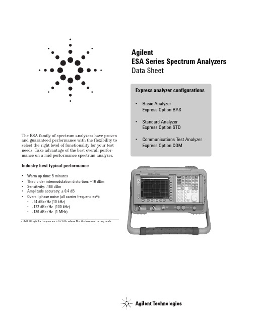
The ESA family of spectrum analyzers have proven and guaranteed performance with the flexibility to select the right level of functionality for your test needs. Take advantage of the best overall perfor-mance on a mid-performance spectrum analyzer. Industry best typical performance•Warm up time: 5 minutes•Third order intermodulation distortion: +16 dBm •Sensitivity: -166 dBm•Amplitude accuracy: ±0.4 dB•Overall phase noise (all carrier frequencies a): •-94 dBc/Hz (10 kHz)•-122 dBc/Hz (100 kHz)•-136 dBc/Hz (1 MHz)AgilentESA Series Spectrum AnalyzersData SheetExpress analyzer configurations •Basic AnalyzerExpress Option BAS •Standard AnalyzerExpress Option STD •Communications Test Analyzer Express Option COMDefinitions and ConditionsThe distinction between specifications and characteristics is described as follows.•Specifications d escribe the performance of parameters covered by the product warranty.(The temperature range is 0 °C to 55 °C, unlessotherwise noted.)•Characteristics d escribe prod uct performance that is useful in the application of the product, but isnot covered by the product warranty.•Typical performance d escribes ad itional prod uct performance information that is not covered by the product warranty. It is performance beyondspecification that 80% of the units exhibit witha 95% confidence level over the temperature range20 to 30 °C. Typical performance does not includemeasurement uncertainty.• Nominal values indicate the expected performance, or describe product performance that is useful in the application of the product, but is not covered by the product warranty.The following conditions must be met for the analyzer to meet its specifications.•The analyzer is within the one year calibration cycle.•If Auto Align All is selected:•After 2 hours of storage within the operating temperature range.•5 minutes after the analyzer is turned on with sweep times less than 4 seconds.•If Auto Align Off is selected:•When the analyzer is at a constant temperature, within the operating temperature range, for aminimum of 90 minutes.•After the analyzer is turned on for a minimum of 90 minutes and Align Now All has been run.•When Align Now All is run:•Every hour•If the ambient temperature changes more than 3 °C•If the 10 MHz reference changes•If Auto Align All but RF is selected:•When the analyzer is at a constant temperature, within the operating temperature range, for aminimum of 90 minutes.•After the analyzer is turned on for a minimum of 90 minutes and Align Now RF has been run.•When Align Now RF is run:•Every hour•If the ambient temperature changes more than 3 °C Table of ContentsDefinitions and Conditions2 Frequency Specifications3 Amplitude Specifications7 General Specifications12 Option Ordering14E4411B Frequency range E4403B E4408B BAS configuration 9 kHz - 1.5 GHz 9 kHz - 3 GHz9 kHz - 26.5 GHzCustom configurationN/AN/A(75 Ω input Option 1DP)1 MHz - 1.5 GHzE4402B E4404B E4405B E4407B STD or COM configuration9 kHz - 3 GHz 9 kHz – 6.7 GHz9 kHz – 13.2 GHz9 kHz - 26.5 GHz Custom configurationLow frequency extension Option UKB 100 Hz a - 3 GHz100Hz a - 6.7 GHz 100Hz a - 13.2 GHz100Hz a - 26.5 GHz External mixing Option AYZAdd 18 GHz - 325 GHzFrequency range Frequency range 100 Hz - 3 GHz2.85 - 6.7 GHz6.2 - 13.2 GHz12.8 – 19.2 GHz18.7 – 26.5 GHzBand 01234Harmonic (N b ) mixing mode1-1-2-4-4-gStandard analyzerCommunications testanalyzer or ESA withOption 1D5±2 x 10⁻⁶/year ±1 x 10⁻⁷/year (Opt. 1D5)±5 x 10⁻⁶/year±1 x 10–8/year b (Opt. 1D5)±5 x 10⁻⁷/year±1 x 10–8/year (Opt. 1D5)[0.5 % + 1/ (sweep points –1) ] x span [0.5 % + 1/ (sweep points –1) ] x span10 MHz1 - 30 MHzLogarithmicN/ARange = 0 Hz (zero span), 100 Hz to maximum frequency range of the analyzer AccuracySwp type linear 1% of span ±[0.5% x span + 2 x span/(sweep points – 1)]2% of span, nominalMarker frequency counter dAccuracy = ±(marker frequency x frequency reference error + counter resolution)Counter resolution = selectable from 1 Hz to 100 kHz Frequency spanSpan coefficient (SP)c 0.75 % x spanExternal reference10 MHzTemperature stability ±5 x 10⁻⁶/year±1 x 10–8/year bSettability ±5 x 10⁻⁷/year±1 x 10–8/yearFrequency readout accuracy (start, stop, center, marker)= ±(frequency indication x frequency reference error + SP c +15% of RBW + 10 Hz + 1 Hz x N a )Aging rate ±2 x 10⁻⁶/year±1 x 10–7/yearBasic analyzer Frequency referenceFrequency reference error = ± [(aging rate x time since last adjustment )+ settability + temperature stability]Standard analyzer Communications test analyzer or ESA with Option AYXor ESA with Option B7D/B7ESpan = 0 Hz 4 ms – 4000 s 50 ns a – 4000 s25 ns a - 4000 sSpan ≥ 100 Hz4 ms – 4000 sRF burst (B7E)Span = 0 Hz 401Span ≥ 100 Hz401Delayed trigger range 1 us to 400 s Sweep (trace) points Range2 - 8192101 - 8192Accuracy± 1%Trigger type bFree Run, Single, Line, Video, Offset, Delayed, ExternalGate (1D6)Basic analyzerSweep time and trigger Range 1 ms – 4000 sCommunications test analyzeror ESA with Option 1DR and 1D5(-3 dB)1 kHz – 5 MHz 1 kHz – 5 MHz 1 Hz to 5 MHz (-6 dB EMI)9 KHz, 120 kHz 9 KHz, 120 kHz 200 Hz, 9 kHz,120 kHz With 1DR c (-3dB)Add 100 Hz, 300 Hz Add 10 Hz - 300 Hz(-6 dB EMI)Add 200 Hz 200 Hz With 1DR and 1D5d N/A Add 1 Hz and 3 HzIncluded 1 Hz to 300 Hz1 kHz to 3 MHz5 MHz100 Hz to 300 Hz1 kHz to 5 MHz Rangewith 1DR < 15:1 synchronously tuned four poles, approximately Gaussian Video bandwidths (1-3-10 sequence)30 Hz to 3 MHz Adds 1, 3, 10 Hz for RBWs less than 1 kHz± 15%± 30%Selectivity (60 dB/3 dB bandwidth ratio)< 5:1 digital, approximately Gaussian RangeIncludedAccuracy± 10%Basic analyzer Standard analyzerResolution bandwidths (1-3-10 sequence)ESA-E E4411BE4403B/08Bwith Option 120aOffset fromCW signal≥ 1 kHz ≥ 10 kHz -93, -95 dBc/Hz-90, -94 dBc/Hz -100, -105 dBc/Hz -100, -105 dBc/Hz-106, -112 dBc/Hz -106, -112 dBc/Hz -118, -122 dBc/Hz -118, -122 dBc/Hz -125, -127 dBc/Hz -127, -129 dBc/Hz -131, -136 dBc/Hz -133, -136 dBc/Hz -135, -139 dBc/Hz -137, -141 dBc/Hz-100, -102 dBc/Hz -104, -106 dBc/Hz -113, -116 dBc/Hz -90, -94 dBc/Hz ≥ 20 kHz ≥ 30 kHz ≥ 100 kHz ≥ 1 MHz ≥ 5 MHz ≥ 10 MHz Option 1D5 only 100 msOption 1DR only 20 msOption 1DR & 1D520 ms≥ 30 kHz offsetfrom carrier CW signalSystem related sidebands ≤ -65 dBc + 20logN c≤ 10 Hz x N c ≤ 2 Hz peak-to-peak x N c≤ 150 Hz x N c (100 ms)≤ 10 Hz x N c (20 ms), Option 1DR≤ 2 Hz peak-to-peak x N c , (20 ms), Option 1DR & 1D5≤ 100 Hz x N c 1 kHz RBW, 1 kHz VBW≤ 150 Hz x N c (100 ms)≤ 30 Hz x N c (20 ms), Option 1DRResidual FM (peak-to-peak)StabilityNoise sidebands offset from CW signal with 1 kHz RBW, 30 Hz VBW and sample detectorSpec, typical dBc/Hz applies to all frequencies ≤ 6.7 GHz b, c -78 dBc/Hz (Option 1D5)Basic analyzerStandard and communications test analyzerE4402B/04B/05B/07BFigure 1. Typical ESA-E Series performance at 1 GHzAmplitude SpecificationsAmplitude specificationFigure 2. Specified dynamic range for E4407B spectrum analyzerInputs/outputsFront panelInput50 Ω type N (f); 75 Ω type N (f) (Option 1DP); 50 Ω APC 3.5 (m) (Option BAB) RF out50 Ω type N (f); 75 Ω BNC (f) (Option 1DQ)Probe power+ 15 Vdc, -12.6 Vdc at 150 mA maximum (characteristic)External keyboard6-pin mini-DIN, PC keyboards (for entering screen titles and file names)Headphone Front panel knob controls volumePower output0.2 Ω into 4 Ω (characteristic)AMPT REF out50 Ω BNC (nominal)IF INPUT (Option AYZ)50 Ω SMA (nominal)LO OUTPUT (Option AYZ)50 Ω SMA (nominal)Rear panel10 MHz REF OUT50 Ω BNC (f), > 0 dBm (characteristic)10 MHz REF IN50 Ω BNC (f), -15 to +10 dBm (characteristic)GATE TRIG/EXT TRIG IN BNC (f), 5 V TTLGATE /HI SWP OUT BNC (f), 5 V TTLVGA OUTPUT VGA compatible monitor, 15-pin mini D-SUB, (31.5 kHz horizontal, 60 Hz vertical sync rates, non-interlaced analog RGB 640 x 480IF, sweep and video ports (Option A4J or AYX)AUX IF OUT BNC (f), 21.4 MHz, nominal -10 to -70 dBm (uncorrected) AUX VIDEO OUT BNC (f), 0 to 1V, characteristic (uncorrected)HI SWP IN BNC (f), low stops sweep, (5 V TTL)HI SWP OUT BNC (f), (5 V TTL)SWP OUT BNC (f), 0 to +10 V rampGPIB interface (Option A4H)IEEE-488 bus connectorSerial interface (Option 1AX)RS-232, 9-pin D-SUB (m)Parallel interface(Option A4H or 1AX)25-pin D-SUB (f) printer port onlyOption OrderingFor information on ordering options, please refer to the ESA/EMC Spectrum Analyzer Configuration Guide, literature number 5968-3412E.More InformationFor the latest information on the Agilent ESA-E Series see our Web page at:Agilent Technologies’ Test and Measurement Support, Services, and Assistance Agilent T echnologies aims to maximize the value you receive, while minimizing your risk and problems. We strive to ensure that you get the test and measurement capabilities you paid for and obtain the support you need. Our extensive support resources and services can help you choose the right Agilent products for your applications and apply them successfully. Every instrument and system we sell has a global warranty. Support is available for at least five years beyond the production life of the product. T wo concepts underlie Agilent’s overall support policy: “Our Promise”and “Your Advantage.”Our PromiseOur Promise means your Agilent test and measurement equipment will meet its advertised performance and functionality. When you are choosing new equipment, we will help you with product information, including realistic performance specifica-tions and practical recommendations from experienced test engineers. When you use Agilent equipment, we can verify that it works properly, help with product operation, and provide basic measurement assistance for the use of specified capabilities, at no extra cost upon request. Many self-help tools are avail-able.Your AdvantageYour Advantage means that Agilent offers a wide range of additional expert test and measurement services, which you can purchase according to your unique tech-nical and business needs. Solve problems efficiently and gain a competitive edge by contracting with us for calibration, extra-cost upgrades, out-of-warranty repairs, and onsite education and training, as well as design, system integration, project management, and other professional engineering services. Experienced Agilent engineers and technicians worldwide can help you maximize your productivity, opti-mize the return on investment of your Agilent instruments and systems, and obtain dependable measurement accuracy for the life of those products./find/emailupdatesGet the latest information on the products and applications you select.Agilent T&M Software and ConnectivityAgilent’s Test and Measurement software and connectivity products, solutions and developer network allows you to take time out of connecting your instruments to your computer with tools based on PC standards, so you can focus on your tasks, not on your connections. Visit /find/connectivity for more information.By internet, phone, or fax, get assistance with all your test & measurement needsOnline Assistance:/find/assistProduct specifications and descriptions in this document subject to change without notice.© Agilent Technologies, Inc. 2004Printed in USA, April 28, 20045968-3386EPhone or FaxUnited States:(tel) 800 829 4444Canada:(tel) 877 894 4414(fax) 905 282 6495China:(tel) 800 810 0189(fax) 800 820 2816Europe:(tel) (31 20) 547 2323(fax) (31 20) 547 2390Japan:(tel) (81) 426 56 7832(fax) (81) 426 56 7840Korea:(tel) (82 2) 2004 5004(fax) (82 2) 2004 5115Latin America:(tel) (305) 269 7500(fax) (305) 269 7599Taiwan:(tel) 0800 047 866(fax) 0800 286 331Other Asia Pacific Countries:(tel) (65) 6375 8100(fax) (65) 6836 0252Email:*******************Agilent Email Updates。
光催化esr的具体测试条件
光催化esr的具体测试条件
光催化ESR(Electron Spin Resonance)测试的具体条件取决于所使用的仪器和实验目的。
以下是一些常见的光催化ESR测试条件:
1. 磁场强度:通常使用高磁场(≥ T)以获得更好的分辨率和灵敏度。
2. 微波频率:通常在 GHz或 GHz的频率下进行测试。
3. 功率:微波功率的调整会影响信号的强度和分辨率,需要根据实验目的和样品特性进行选择。
4. 温度:测试温度会影响分子的自旋状态和弛豫时间,通常在较低的温度下进行测试以获得更好的信号。
5. 样品量:需要适量的样品以确保信号强度和稳定性。
6. 基质:如果需要将样品固定在固体基质上,应选择合适的基质以避免干扰ESR信号。
7. 光源:对于光催化ESR测试,需要使用合适的光源(如紫外灯、可见光灯等)以激发样品中的光催化剂并产生自由基。
请注意,这些条件只是一些常见的参数,具体实验条件应根据所研究的样品和实验目的进行选择和调整。
在进行光催化ESR测试之前,建议仔细阅读仪器说明书并咨询相关领域的专家。
- 1、下载文档前请自行甄别文档内容的完整性,平台不提供额外的编辑、内容补充、找答案等附加服务。
- 2、"仅部分预览"的文档,不可在线预览部分如存在完整性等问题,可反馈申请退款(可完整预览的文档不适用该条件!)。
- 3、如文档侵犯您的权益,请联系客服反馈,我们会尽快为您处理(人工客服工作时间:9:00-18:30)。
Benchtop instruments like the Agilent Technologies PSA series offer laboratory performance plus a wide range of options and analysis capabilities.
cations such as CATV, SATCOM, WLAN or any of the wireless phone standards, including new 2.5G and 3G systems. All major manufacturers address the market niche with various models. A representative example is the Rohde & Schwarz FSL, pictured above. The FSL features a large number of standard functions, including a choice of detectors: max, min, autopeak, sample, RMS, average, quasipeak; CP/ACP/fast ACP measurement functions with a host of predefined standards; time domain power measurement; carrier-to-noise ratio C/N or C/N0 referenced to 1 Hz or channel bandwidth; CCDF: measurement of crest factor and amplitude probability function. All of today’s full-feature portable and benchtop instruments include full programmability, typically with a stand-alone Windows-based operating system and LAN-based or Internet protocol communications to other computers or instruments. Digital IF filters and digital analysis features are either standard or optional, depending on the particular model. DANL performance may range from –115 dBm to –150 dBm depending on the intended application, frequency range and price. These portable units are often used as the primary laboratory spectrum analyzer at many RF/microwave companies. 52
With today’s complex wireless systems, portable instruments must have performance like their laboratory counterparts. This example is the Rohde & Schwarz model FSL.
external memory devices. The Rohde & Schwarz FSH3 handheld spectrum analyzer includes many of the features of the above unit, with specs that include 100 kHz to 3 GHz range to cover popular wireless bands, DANL of –135 dBm (RBW 100 Hz). Resolution bandwidths range from 100 Hz to 1 MHz. This unit offers sample, max/min peak, auto peak and RMS detectors, and has an optional tracking generator.
By Gary Breed Editorial Director pectrum analyzers are among the most common RF and microwave test instruments. Viewing, measuring and analyzing signals in the frequency domain is their fundamental job, but the ability to perform those tasks has improved markedly in a relatively short time. This month’s tutorial is a review of the significant improvements in features and performance that instrument manufacturers have made to this important engineering tool over the past several years.
High Frequency Design
SPECTRUM ANALYZERS
From August 2005 High Frequency Electronics Copyright © 2005 Summit Technical Media
An Update on Features and Performance in Today’s Spectrum Analyzers
High Performance s
Although handhelds are extremely convenient for many field engineering and service tasks, traditional form factor portable spectrum analyzers remain popular. They can provide basic performance that nearly equals laboratory instruments. Models from various makers cover from 4 GHz to beyond 40 GHz. Features are often tailored for specific appli-
High Frequency Design
SPECTRUM ANALYZERS
Benchtop Instruments
In the engineering laboratory, it is important to have test instruments that noise, dynamic range and bandwidth performance that allows full and precise characterization of any design, no matter how complex or high performance. Benchtop instruments fill that need. In this segment of technology is the Agilent PSA series (right), a family of six models covering from 3 Hz up to 6.7, 13.2, 26.5, 42.98, 44 or 50 GHz. External mixers allow three models to operate up to 325 GHz. With –153 dBm DANL and +19 dBm third order intercept (TOI), these analyzers cover a wide dynamic range. At this high performance level, highly accurate frequency and amplitude characteristics are required. The PSA series provides ±0.17 dB typical amplitude accuracy and ±0.05 dB RBW switching uncertainty. Attention is also paid to ease of use (a relative term given the flexibility of today’s instruments). Onebutton menu selection of the most common commands is included for general operation, while at the complex level, specific “personalities” are included for various standards. These are supported by options such as digital demodulation and wide bandwidth digitizers to capture and analyze signals. Beyond basic spectrum analysis, instruments are also available for
High Frequency Electronics
