PM-120网关产品手册_V2.4
PM配置文档

深圳博康系统IVG网络视频管理平台PM配置文档2010-08-10目录深圳博康系统IVG网络视频管理平台 (1)第1章软件概述 (3)第2章软件配置 (4)2.1 运行PM软件 (4)2.2 新建/打开/保存db文件 (4)2.3 服务器标题配置 (4)2.4 编号映射表配置 (4)2.5 视频服务器配置 (5)2.6 数字摄像机配置 (5)2.7 用户配置 (8)2.7.1 新建用户 (8)2.7.2 修改用户属性 (8)2.7.3 用户授权 (9)2.8 用户组配置 (10)第1章软件概述PowerManager软件简称PM软件。
是IVG系统的配置软件,负责系统所有数据库文件的生成/配置/导入/导出等等。
IVG系统涉及到的所有设备,包括:编解码器,矩阵,串口,报警设备,键盘,用户等都需要事先通过PM软件配置,配置完成后通过PM软件把数据库文件导入到IVG服务器,然后系统即可正常工作。
第2章软件配置2.1运行PM软件鼠标左键双击PM软件程序,或者点鼠标右键选择“打开”,PM软件程序图标如下:2.2新建/打开/保存db文件PM软件正常运行之后,方可对该软件进行后续操作。
点“文件”,在下拉菜单里面可选择“新建/打开/关闭/保存/另存/下载/上传/退出”等操作,如下图:2.3服务器标题配置鼠标左键点击根目录,修改右边的“系统信息-系统属性-系统标题”,如下图:2.4编号映射表配置鼠标左键点击“配置-编号映射表-节点编号”,在下方节点编号对话框里面配置IVG服务器的节点编号,如下图2.5视频服务器配置鼠标左键点击“视频服务器”,在右边的“批添加服务器”对话框里面添加视频服务器,如下图服务器-视频服务器的ip地址;标题-可任意;型号-VS600 ENCODER HOST;端口-8000;用户名-admin;密码-12345;配置完成后,密码栏显示空白,但实际上已经配置好了。
2.6数字摄像机配置创建“摄像机/编解码通道”,如下图,在“摄像机/监视器/编解码通道”上点鼠标右键,选择“创建摄像机/编解码通道(C)”配置数字摄像机的名称和标题,然后选择下一步配置数字摄像机的对象类型,如下图。
产品使用说明书
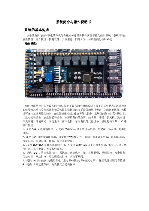
系统简介与操作说明书系统的基本构成该系统由弱电控制强电的方式配合相应传感器和软件实现智能化控制系统,系统结构由输出模组、输入模组、控制软件、云端服务、四部分为一体的智能化控制系统。
输出模组:输出模组是控制各类设备的电源,控制了设备的电源就控制了设备的工作状态,通过设备的信号输入端接受传感器和相关软件的数据就改变了设备的运行模式,完成智能运行,该模组可支持工业智能化控制、农业智能化控制、建筑智能化控制、家居智能化控制等领域。
如:工业电机和设备、农业浇灌和设备、家居设备的的空调、热水器、地暖、新风机、洗衣机、灯光照明、环境调光、家电集成、窗帘电机、车库电机等其他设备,模组提供了共计32路接口输出。
1、8路30A大电流输出口,可支持220V/6kw以下的设备负载,如空调、热水器、功率电机等。
2、8路16A可控硅调压输出,可支持220V/3kw以下的调压调速设备负载,如车库电机、推窗电机、窗帘电机、灯具、等及其他设备。
3、16路16A+16A双触点并联输出口,可支持220V/5kw以下的设备负载,如室内灯光、环境灯光、家用电器、等及其他设备。
4、提供12/24V清洁电源接口,系统支持直流供电、如:常规照明、视频监控、安全报警、门禁对讲、网络供电、可实现持续供电,断电不断网。
5、提供3+1供电接口为模组供电(主电源+辅助电源+直流电源),保证设备长期可靠待机。
6、提供16路过流保护,为设备安全提供保障。
输入模组:输入模组是系统的心脏,包含控制输出、手动控制输入、自动控制输入、传感器输入、工业控制信号输入、视频监控信号输入、报警信号输入、门禁信号输入、红外线信号输入、射频信号输入、网络输入、总线控制输入等。
1、控制输出接口:连接输出模组,将系统的工作状态传递给输出模组,驱动继电器完成动作。
手动输入接口:提供32进32出的手动控制接口,输入输出对应控制输出,自适应传统的各类型控制面板(翘板开关、轻触开关),可操作系统的开、关、调光、调速等的模式转换等功能,与系统控制APP全兼容,控制状态同步显示,即使系统的核心芯片因某种原因出现故障,也不影响系统的基本功能使用。
【8A版】PM项目管理系统操作说明书
信息化建设项目PM项目管理系统操作说明书文档编号:PM-001作者:信息化小组版本:V1.0创建日期:20XX年9月10日文档说明此文档说明适用于《建筑云PM项目系统操作说明书》。
文档类别此文档属于项目实施的重要过程文档,是系统管理员日常工作的必要参考和重要依据。
编写目的为系统操作人员的日常工作提供必要的支持和帮助,从而确保系统能够平稳运行,并且帮助系统操作人员更加快速有效地解决系统运行过程中出现的问题。
使用方法此文档甲方项目经理提供模板,双方项目经理结合客户的具体情况共同编辑完善,最后作为项目的成果保存给客户,并发放系统操作人员使用。
文档依据《系统运行管理制度》使用对象该文档使用人员包括:项目领导、项目组成员及其它项目相关人员;项目领导、项目组成员及其他项目相关人员;获得授权的第三方人员。
编制工具MicrosoftWord20XX文档控制文档变更记录文档审核记录文档去向记录目录文档说明 (2)文档控制 (3)第一章系统概述 (6)1.1产品介绍 (6)1.2主要功能 (6)1.3产品接口 (8)1.4操作规程 (8)1.5操作说明 (8)1.6系统通用操作 (9)1.6.1单击操作 (9)1.6.2导航介绍 (9)1.6.3添加操作 (9)1.6.4编辑操作 (10)1.6.5删除操作 (11)1.6.6查询操作 (11)1.6.7打印操作 (12)1.6.8多附件上传操作 (13)1.6.9导出操作 (15)第二章项目管理 (16)2.1项目管理系统概述 (16)2.1.1系统功能框架 (17)2.1.2系统分层应用逻辑 (17)2.2项目信息 (18)2.3(A)投标管理 (19)2.3.A1系统概述 (19)2.3.A2应用逻辑 (20)2.3.A3主要功能 (21)2.3(B)招标管理 (22)2.3.B1系统概述 (22)2.3.B2应用逻辑 (23)2.3.B3主要功能 (24)2.4合同管理 (25)2.4.1系统概述 (25)2.4.2应用逻辑 (26)2.4.3主要功能 (26)2.5进度管理 (31)2.5.1系统概述 (31)2.5.2应用逻辑 (32)2.5.3主要功能 (32)2.6成本管理 (35)2.6.1系统概述 (35)2.6.2应用逻辑 (36)2.6.3主要功能 (36)2.7质量管理 (41)2.7.1系统概述 (41)2.7.2应用逻辑 (42)2.7.3主要功能 (42)2.8安全管理 (45)2.8.1系统概述 (45)2.8.2应用逻辑 (46)2.8.3主要功能 (46)2.9技术管理 (50)2.9.1系统概述 (50)2.9.2应用逻辑 (51)2.9.3主要功能 (51)2.10物资管理 (54)2.10.1系统概述 (54)2.10.2应用逻辑 (55)2.10.3主要功能 (55)2.11设备管理 (56)2.11.1系统概述 (56)2.11.2应用逻辑 (57)2.11.3主要功能 (57)2.12环境管理 (59)2.13竣工管理 (59)2.13.1系统概述 (59)2.13.2应用逻辑 (60)2.13.3主要功能 (60)2.14相关方管理 (62)2.14.1系统概述 (59)2.14.2主要功能 (60)第三章流程中心 (63)3.1工作流程发起 (63)3.2我的流程 (64)3.2.1我的待办任务 (64)3.2.2我发起的流程 (66)3.2.3我参与的流程 (67)3.2.4流程委托他人 (68)3.2.5发起工作流程 (70)第一章系统概述1.1产品介绍PM项目管理系统(以下简称PM系统)是为配合公司企业信息化建设顺利实施研制的管理系统。
PM-127_V32_UM
PM测试软件使用手册

本手册适用于软件版本 V1.03 Copyright © 2009-7-24本手册版本V1.01北京博电新力电力系统仪器有限公司版权所有本手册中的产品信息、说明以及所有技术数据均不具有合同约束力。
北京博电新力电力系统仪器有限公司(下简称北京博电公司)保留对产品技术数据进行修改而不另行通知的权利。
产品与本手册不符之处,以实际产品为准。
北京博电公司对于本手册中可能发生的错误不承担责任。
未经北京博电公司书面许可,不得全部或部分拷贝、重印该手册。
注意事项PM测试软件是与PM系列电力自动化测试装置配套使用的专用测试软件。
PM测试软件安装在台式或便携式计算机上,运行在Windows XP操作系统下。
PM测试装置使用USB信号线或以太网双绞信号线与计算机连接,由PM测试软件对测试装置进行联机控制。
联机工作时应保证信号线可靠连接,注意不要随意拉扯信号线或晃动信号线连接端。
PM测试装置为高精度电子仪器;为保证输出和测量的精度,装置开机后应预热30min以上。
目录注意事项 (3)目 录 (4)1.软件概述 (6)1.1. 软件启动 (6)1.2. 测控装置功能测试 (7)1.3. 计算机监控系统功能测试 (8)1.4. 变送器功能测试 (8)2.软件和通讯驱动程序安装 (9)2.1. 软件安装 (9)2.2. USB口装置驱动程序安装 (9)3.通讯设置 (15)3.1. PM设备接口选择 (15)3.2. 网口PM设备联机通讯设置 (16)3.3. 闭环通讯设置 (20)4.手动测试 (25)4.1. 概述 (25)4.2. 测试参数设置 (26)4.3. 手动输出 (30)5.交流采样自动测试 (31)5.1. 概述 (31)5.2. 测试参数设置 (33)5.3. 测试接线 (42)5.4. 测试操作 (43)6.变送器自动测试 (47)6.1. 概述 (47)6.2. 测试参数设置 (48)6.3. 测试接线 (56)6.4. 测试操作 (56)7.同期测试 (58)7.1. 概述 (58)7.2. 测试参数设置 (60)7.3. 测试接线 (65)7.4. 测试操作 (66)8.谐波测试 (68)8.1. 概述 (68)8.2. 测试参数设置 (68)8.3. 谐波输出 (69)8.4. 谐波测试实例 (69)9.系统测试 (70)9.1. 概述 (70)9.2. 测试参数设置 (71)9.3. 测试接线 (75)9.4. 测试操作 (75)附录A 点表设置程序使用说明 (77)附录B 点表命名说明 (89)附录C 交流采样闭环校验报告实例 (91)1.软件概述PM测试软件是与PM系列电力自动化测试装置配套使用的专用测试软件。
中移动家庭网关终端技术规范v ()

中国移动通信企业标准QB-╳╳-╳╳╳-╳╳╳╳家庭网关终端技术规范T e c h n i c a l S p e c i f i c a t i o n f o r H o m e G a t e w a y版本号:3.0.0╳╳╳╳-╳╳-╳╳发布╳╳╳╳-╳╳-╳╳实施中国移动通信集团公司发布目录2.规范性引用文件...............................................................................................................................3.术语、定义和缩略语 .......................................................................................................................4.设备总体定义...................................................................................................................................4.1.设备在网络中的位置 ....................................................................................................................4.2.接口定义........................................................................................................................................4.3.设备类型........................................................................................................................................5.接入型家庭网关...............................................................................................................................5.1.接口要求........................................................................................................................................网络侧接口........................................................................................................................................网络侧接口描述............................................................................................................................................网络侧以太网接口要求................................................................................................................................PON接口要求.................................................................................................................................................TD-SCDMA接口要求.......................................................................................................................................TD-LTE接口要求...........................................................................................................................................用户侧接口........................................................................................................................................用户侧以太网接口要求................................................................................................................................WLAN接口 ......................................................................................................................................................USB接口(可选).........................................................................................................................................5.2.功能要求........................................................................................................................................数据通信要求....................................................................................................................................IP协议要求 ..................................................................................................................................................数据转发功能要求........................................................................................................................................DNS功能要求.................................................................................................................................................IPv4地址管理及拨号管理功能要求 ...........................................................................................................IPv6地址管理及拨号管理功能要求 ...........................................................................................................IPv4NAT要求.................................................................................................................................................ALG要求 ........................................................................................................................................................组播要求 .......................................................................................................................................................其他功能要求................................................................................................................................................安全要求............................................................................................................................................防火墙 ...........................................................................................................................................................登陆WEB页面的安全要求............................................................................................................................设备安全性 ...................................................................................................................................................QoS要求.............................................................................................................................................VLAN功能要求...................................................................................................................................USB扩展及管理(可选).................................................................................................................设备发现要求....................................................................................................................................UPnP ...............................................................................................................................................................DLNA(可选)................................................................................................................................................支持WLAN的开启和禁用..............................................................................................................................基本要求 .......................................................................................................................................................多SSID要求 .................................................................................................................................................WLAN安全要求...............................................................................................................................................5WLANQoS要求...............................................................................................................................................WPS要求 ........................................................................................................................................................ 基本应用要求.....................................................................................................................................WLAN共享 ....................................................................................................................................................家庭存储(可选)........................................................................................................................................5.3.性能要求........................................................................................................................................ 路由转发性能要求............................................................................................................................吞吐量 ...........................................................................................................................................................地址学习 .......................................................................................................................................................缓存大小 .......................................................................................................................................................连接数量要求................................................................................................................................................ WLAN无线性能要求...........................................................................................................................WLAN吞吐量性能要求...................................................................................................................................WLAN覆盖性能要求.......................................................................................................................................WLAN接收灵敏度要求...................................................................................................................................5.4.管理和维护要求............................................................................................................................ 本地管理和配置要求........................................................................................................................本地管理基本要求........................................................................................................................................用户分级管理................................................................................................................................................系统信息管理................................................................................................................................................基本配置 .......................................................................................................................................................高级配置 .......................................................................................................................................................设备管理 .......................................................................................................................................................网络诊断 .......................................................................................................................................................设备认证注册功能........................................................................................................................................ 远程管理要求....................................................................................................................................远程管理基本要求........................................................................................................................................远程参数配置和性能监测............................................................................................................................远程故障诊断功能........................................................................................................................................设备告警功能................................................................................................................................................远程链路维持功能........................................................................................................................................软件远程管理................................................................................................................................................业务部署和控制............................................................................................................................................PON上行家庭网关远程管理实现方式 ......................................................................................................... 日志功能要求....................................................................................................................................5.5.预配置要求.................................................................................................................................... 预配置要求........................................................................................................................................5.6.硬件要求........................................................................................................................................ 基本要求............................................................................................................................................硬件基本框图示例............................................................................................................................5.7.软件要求........................................................................................................................................基本要求............................................................................................................................................软件基本架构....................................................................................................................................软件接口要求....................................................................................................................................用户登录要求....................................................................................................................................系统升级要求....................................................................................................................................5.8.配置界面要求................................................................................................................................配置界面要求....................................................................................................................................配置界面用户权限要求....................................................................................................................5.9.设备标识要求................................................................................................................................5.10.外观及附件要求..........................................................................................................................运营商Logo要求..............................................................................................................................设备标签要求....................................................................................................................................网关指示灯要求................................................................................................................................开关与按键要求................................................................................................................................设备面板标识要求............................................................................................................................设备接口要求....................................................................................................................................附件要求............................................................................................................................................5.11.运行环境要求..............................................................................................................................供电要求............................................................................................................................................环境要求............................................................................................................................................抗电磁干扰能力................................................................................................................................设备本身产生的电磁干扰要求........................................................................................................过压过流保护....................................................................................................................................5.12.认证要求......................................................................................................................................6.接入型家庭网关支持物联网功能 ....................................................................................................6.1.接入型家庭网关支持宜居通的功能要求(内置433M模块)...................................................433M模块要求...................................................................................................................................外围设备要求....................................................................................................................................业务功能描述....................................................................................................................................安防功能要求................................................................................................................................................家电控制功能................................................................................................................................................接入型家庭网关配置界面要求........................................................................................................配置界面要求................................................................................................................................................配置界面用户权限要求................................................................................................................................6.2.接入型家庭网关支持基于低功耗W I F I的物联网功能要求..........................................................设备接入功能要求............................................................................................................................WiFi接入.......................................................................................................................................................接入型家庭网关要求 ...............................................................................................................................外设要求...................................................................................................................................................DHCP流程要求 .............................................................................................................................................7.宽带应用型家庭网关 .......................................................................................................................7.1.类型描述..........................................................................................................................................7.2.分体机接入设备要求......................................................................................................................7.3.分体机应用设备(机顶盒)要求 ..................................................................................................硬件要求............................................................................................................................................硬件、接口及按键要求................................................................................................................................遥控器要求及参考设计................................................................................................................................电源要求 .......................................................................................................................................................配件要求 .......................................................................................................................................................设备标识要求................................................................................................................................................网络侧接口要求................................................................................................................................业务功能要求....................................................................................................................................互联网电视应用............................................................................................................................................多屏互动功能................................................................................................................................................概述...........................................................................................................................................................镜像功能...................................................................................................................................................分享功能...................................................................................................................................................家庭高清视频通话(可选)........................................................................................................................家庭卡拉OK功能(可选) .........................................................................................................................语音交互功能................................................................................................................................................软件要求............................................................................................................................................操作系统要求................................................................................................................................................软件协议要求................................................................................................................................................编码及解码能力要求....................................................................................................................................编解码能力要求 .......................................................................................................................................音视频播放质量要求 ...............................................................................................................................屏幕管理要求................................................................................................................................................防刷机要求 ...................................................................................................................................................管理要求............................................................................................................................................操作管理 .......................................................................................................................................................软件管理 .......................................................................................................................................................文件管理 .......................................................................................................................................................4.配置管理 ....................................................................................................................................................其他要求............................................................................................................................................供电要求 .......................................................................................................................................................环境要求 .......................................................................................................................................................噪声要求 .......................................................................................................................................................7.4.一体机设备要求............................................................................................................................网络侧接口要求................................................................................................................................网络接入功能要求............................................................................................................................业务功能要求....................................................................................................................................软件要求............................................................................................................................................管理要求............................................................................................................................................硬件要求............................................................................................................................................其他要求............................................................................................................................................供电要求 .......................................................................................................................................................环境要求 .......................................................................................................................................................噪声要求 .......................................................................................................................................................8.编制历史 .......................................................................................................................................... 附录A省公司代码.......................................................................................................................... 附录B设备故障消息(标准性附录) ...........................................................................................B.1告警编号规则 ...............................................................................................................................B.2设备告警信息列表 ....................................................................................................................... 附录C WIMO协议说明.....................................................................................................................C.1设备类型和功能流程 .....................................................................................................................C.2网络连接.........................................................................................................................................C.3设备连接.........................................................................................................................................C.4媒体格式要求.................................................................................................................................C.4.1视频编解码流程.....................................................................................................................C.4.2M-JPEG视频编解码方案.........................................................................................................C.4.3H.264视频编解码方案...........................................................................................................C.4.4音频编解码流程..................................................................................................................... 附录D手机遥控接口说明 ..............................................................................................................D.1设备发现.........................................................................................................................................D.2配对请求接口.................................................................................................................................D.3配对连接接口.................................................................................................................................D.4发送遥控器键值接口 .....................................................................................................................D.5发送文本接口.................................................................................................................................D.6发送心跳接口.................................................................................................................................D.7断开连接接口.................................................................................................................................D.8配对成功广播发送接口 .................................................................................................................D.9配对断开广播发送接口 ................................................................................................................. 附录E宽带应用型家庭网关牌照合作注册机制............................................................................ 附录F家庭网关命名规则 ..............................................................................................................。
PMM安装与用户手册
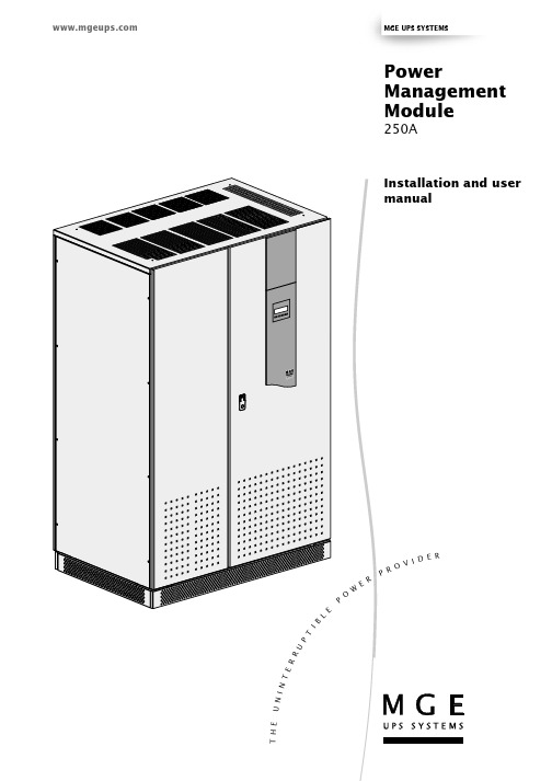
34020201EN/AB - Page 1MGE UPS SYSTEMSInstallation and usermanualPowerManagement Module250AT H E U N I N T E RRUPTIBLP OWERPR OVI D E RPage 2 - 34020201EN/AB34020201EN/AB - Page 3IntroductionThank you for selecting an MGE UPS SYSTEMS product to protect your electrical equipment.The Power Management Module (PMM) has been designed with the utmost care. We recommend that you take the time to read this manual to take full advantage of the many features of your new equipment.MGE UPS SYSTEMS pays great attention to the environmental impact of its products.The considerable resources put into developing the Power Management Module make it a reference in terms of environmental protection. Of particular importance are:◗ the eco-design approach during product development,◗ recycling of the Power Management Module at the end of its service life.MGE UPS SYSTEMS warrants this hardware product against defects in materials and workmanship for a period of one year.Limitation of warranty: the above warranty shall not apply to defects resulting from: misure, non-MGE UPSSYSTEMS modification, operation or storage outside the environmental specifications for the product, improper maintenance, or defects resulting from use of non-MGE UPS SYSTEMS software, accessories, -media or such items not designed for use with the product.Moreover, the warranty does not include the consumable goods and the replacements or repairs which would result from the abnormal wear of the products, and deteriorations or accidents coming from an external cause such as fire, damage of water, damage caused by other equipment...We invite you to discover the entire MGE UPS SYSTEMS range of products and services including the options for the Power Management Module by visiting our Web site at or by contacting your nearest sales representative.To take into account evolving standards and technology, equipment may be modified without notice. Indications concerning technical characteristics and dimensions are not binding unless confirmed by MGE UPS SYSTEMS.This document may be copied only with the written consent of MGE UPS SYSTEMS. Authorized copies must be marked "Power Management ModuleUser Manual nr 3402020100".Page 4 - 34020201EN/ABStructure of this documentMandatory instructionsGeneral instructions, advice, helpIndicationActionSymbolsInformation may be found via:◗ the contents,◗ the index.Earth cablesOther cablesForewordContents1.Presentation1.1250 A PMM modules (6)1.2Access to the circuit breakers (7)Version with 126 circuit breakers (doors open) (7)Version with 60 circuit breakers (doors open) (7)1.3Access to connections (8)1.4Control panel (8)2.Installation2.1Setting up the module (9)Module 825 mm deep (9)Module 425 mm deep (10)2.2Input power connections (12)2.3Output circuit connections (14)2.4Alarm and remote shutdown connections (14)2.5Communication connections (15)3.Operation3.1Turning on the PMM module (16)3.2Display (16)3.3Metering (16)Output-circuit metering (17)General metering (17)3.4Alarms (17)3.5Setup (18)Communication settings (18)Operation settings (display and alarms) (18)3.6Turning off the PMM module (18)4Maintenance4.1Trouble-shooting and solutions (19)5Environment (20)6.Appendices6.1Technical data sheets (21)Electrical characteristics (21)Thermal characteristics (21)Noise level (21)Maximum wire sizes for terminal blocks (21)Recommended upstream protection devices (21)Standards (21)6.2Simplified diagrams (22)Version with isolation transformer (22)Version without isolation transformer (22)6.3Auxiliary contact functions (23)6.4Modbus communication information (23)Access to communicated information (23)Cards BCM1, BCM2 and BCM3 (status and measurements for 42 or 21 output circuits) (24)Card MCM (general status and measurements) (31)6.5Glossary (32)6.6Index (33)34020201EN/AB - Page 5Page 6 - 34020201EN/AB1. Presentation1.1 250 A PMM modulesModule characteristicsYou can choose from 6 different modules depending on:◗ the number of output circuits required and the type of protection (126 standard circuit breakers or 60 circuit breakers with earth-leakage protection),◗ the presence of an isolation transformer,◗the depth (825 with or without an isolation transformer and 425 without).Control panel with display1. Presentation1.2Access to the circuit breakersVersion with 126 circuit breakers (doors open)Version with 60 circuit breakers (doors open)F1 disconnector-fuse for protection of thecontrol electronicsUpstream general protection circuit breaker(only in modules with an isolationtransformer)General protection circuit breaker for the 126output circuits2 x 21 circuit breakers for phase A (A-1 to A-41 and A-2 to A-42)2 x 21 circuit breakers for phase B (B-1 to B-41 and B-2 to B-42)2 x 21 circuit breakers for phase C (C-1 toC-41 and C-2 to C-42)Upstream general protection circuit breaker(only in modules with an isolationtransformer)General protection circuit breaker for the 60output circuitsF2 disconnector-fuse for protection of thevoltage measurement inputsF1 disconnector-fuse for protection of thecontrol electronics2 x 10 circuit breakers with earth-leakageprotection for phase A (A-1 to A-19 and A-2to A-20)2 x 10 circuit breakers with earth-leakageprotection for phase B (B-1 to B-19 and B-2to B-20)2 x 10 circuit breakers with earth-leakageprotection for phase C (C-1 to C-19 and C-2to C-20)F2 disconnector-fuse for protection of thevoltage measurement inputsEight connection cover panelsEight connection cover panels34020201EN/AB - Page 7Page 8 - 34020201EN/AB1. Presentation1.3Access to connectionsRemove the eight cover panels (each secured with two screws).Example showing the version with 126 output circuits:Metal trunking for passage and securing of output cablesConnection bars for earth wires of output cablesTerminal block for remote shutdown function and minor and major alarmsIn modules with an isolation transformer, of the three input phases to circuit breaker Q1In modules without an isolation transformer,connection of the three input phases and the neutral to circuit breaker Q2Phase connections for output-circuit cables1.4Control panelAlphanumeric displaySystem status LED: see table on page 23Scroll through different types ofmeasurements or return to display of measurementsScroll through different system settings Previous measurement or setting Next measurement or settingMain earthing bar of the module34020201EN/AB - Page 92. Installation2.1Setting up the moduleModule 825 mm deep1.Install the lower base panels 23 on the sides that will not be accessible (not mandatory).2.Position the module.3.Level the module using the adjustable feet 24 .4.Install the lower base panels 23 on the visible sides.Footprint of moduleWeight exerted on the floor by the four feet:◗ 28 kg/cm 2 (module without transformer),◗ up to 72 kg/cm 2 (module with transformer).Connection cables run under the false floor or in a cable trough.Important.At least 400 mm of free space is required above the module to ensure correct ventilation.At least 720 mm of free space is required in front to open the doors.Page 10 - 34020201EN/AB2. InstallationModule 425 mm deepFootprint of moduleForce exerted on the floor by the four feet:◗ 28 kg/cm 2.Installation against a wall1.Turn to horizontal position the twobrackets 25 at the back used to secure the module (see figure).Back-to-back assembly2. InstallationLevel the modules using the adjustablefeet 24 .Install the base panels 23 on the sides Caution: during handling, make sure the modules do not fall over.Remove the brackets 25 on the back ofPosition the modules and use thebrackets 26 on the top to interconnect the(see figure).2.22. Installation2.32.4Alarm and remote shutdown connections1.Connect the NO remote shutdown contact to terminals 1 and 2 on terminal block 13 .2.The alarm signals are transmitted by dry contacts (Umax = 250 V AC / 30 V DC, Imax = 7 A AC / 10 A DC) between terminals 3and 4 for the type 1 alarm and between 5and 6 for the type 2 alarm.3.Tie the cable down to the module frame.It is advised to use crimped ferrules on the phase wires and lugs on the earth wires.1.Connect the earth wire of each output cable to the earth connection bar located to the left of the metal trunking.2.Connect the phase and neutral wires to each circuit breaker.3.Tie the cables to the metal trunking.Note : it is advised to make the connections from the top down.Warning: the remote shutdown function is not implemented using a very low safety voltage.Consequently, the usual safetymeasures must be taken to avoid all risk of electrical shock when making connections for this function.2. Installation 2.5Communication connections1.Connect the communication cable to theRS232 or RS485 connector on the right-hand door of the module.2.Run the cable as shown in the figureopposite.3.Tie the cable down to the module frame.Communication connector detailsRS485 connector2 wiresGNDTx+Tx-Tx+ / Rx+Tx- / Rx-RS485 connector4 wiresGNDRx+Rx-Not usedNot usedExample of an RS485 2-wireconnection:Example of an RS485 4-wire connection:Master SlaveMaster or slavex-/Rx-x+/Rx+ND x-x+NDx-x+x-x+NDx-x+3.Operation3.1Turning on the PMM module1.Close the upstream switching device (external and not supplied) on the circuit supplying the PMM module.2.In a module with an isolation transformer, close ("I" or ON position) circuit breaker Q1 5 (see page 7) .3.Make sure disconnector-fuses F1 and F2 are closed and close ("I" or ON position) circuit breaker Q2 5 (see page 7) .◗ The system status LED 17 (see page 8) flashes yellow a few seconds, then green and should subsequently remaingreen.◗ After a few seconds, the first page of measurements is displayed:3.2Display4.Close the circuit breakers on the output circuits to be powered.Metering modeThe display unit for the PMM module offers three operating modes: metering, alarm and setup.3. Operation3.4AlarmsAlarm text:WARNING: indicates that the current on the indicated circuit (number25, phase B) is between 60 and 80% of the maximum value.This mode displays the list of stored major and minor faults that have occurred in the PMM or on the output circuits.When an alarm is present in the memory, LED 17 goes on:◗yellow for fault that does not hinder normal operation;◗red for a fault requiring intervention.3.3MeteringPh-A:measurements on phase ADisplay of the current drawn by the output circuit in amperesOutput-circuit meteringGeneral meteringGENE: general measurements.Measurement units:KWH: total energy consumed by the PMM module in kWh.This value can be reset via the communication function.KW: total active power drawn by the PMM module in kW.KVAR: reactive power drawn by the PMM module in kVAR.rotation). The display flashes and the measurement is not updated.KVA: apparent power drawn by the PMM module in kVA.PF: average power factor on the three phases of thePMM module.V-LL: average phase-to-phase voltage on the three phases of the PMM module in volts.V-LN: average phase-to-neutral voltage on the three phases of thePMM module in volts.AMPS: average current on the three phases of the PMM module in amperes.FREQ: frequency of the voltage supplied by the PMM module in Hertz.KW-A, KW-B, KW-C: active power drawn by phases A, B and C of the PMM module in kW.PF-A, PF-B, PF-C: power factor on phases A, B and C of the PMM module.V-AB, V-BC, V-AC: phase-to-phase voltages supplied by the PMM module in volts.V-AN, V-BN, V-CN: phase-to-neutral voltages supplied by the PMM module in volts.AMPA, AMPB, AMPC, AMPN: current on the three phases A, B, C and on the neutral of the PMMmodule in amperes.MIN: minimum power (stored in memory) supplied by the PMM module in kW since the last reset.MAX: maximum power (stored in memory) supplied by the PMM module in kW since the last reset.The minimum, maximum and average power values are reset via the communication function.Ph-B: alarm on phase B.CH-25: alarm on output circuit 25.These alarms are stored in memory:◗◗The display automatically returns to metering mode if buttons 19 to 22 are not used for ten seconds.ALARM: indicates that the current on the indicated circuit is higher than 80% of the maximum value.OVER VOLTAGE: the voltage supplied by the PMM exceeds the permissible range by over 10%.OVER CURRENT: there is an overload on the PMM.AUX INPUT ALARM: this alarm signals either:◗ excessive temperature rise in the isolation transformer,◗ or activation of the remote shutdown button.CH-01:measurements on output circuit 013.Operation3.5SetupCommunication settingsSettings include:◗ Routing Address (ON, OFF): internal setting reserved for MGE UPS SYSTEMS, must not be modified (ON).◗ Modbus Address (1 to 225): Modbus address, must be selected from 1 to 225 (by steps of 16).◗ Upstream Type (RS-485, RS-232, INFRARED): type of serial link.◗ Upstream Duplex (2-WIRE, 4-WIRE): 2 or 4-wire link.◗ Upstream Baudrate (2400, 4800, 9600, 19200): speed of transmission in Bauds.◗ Upstream Parity (NONE, ODD, EVEN): parity.◗ Downstream Duplex : internal setting reserved for MGE UPS SYSTEMS, must not be modified (2-WIRE).◗ Downstream Baudrate : internal setting reserved for MGE UPS SYSTEMS, must not be modified (9600).◗ Downstream Parity : internal setting reserved for MGE UPS SYSTEMS, must not be modified(NONE).Operation settings (display and alarms)The user-settable parameters are listed below.◗ Blacklight Brightness (0 to 9): adjustment of the display luminosity.◗ Auxiliary INPUT ALARM : internal setting reserved for MGE UPS SYSTEMS, must not be modified (CLOSED).◗ Rotate parameters(NO, YES) : fixed display or autoscroll.3.6Turning off the PMM module1.Open ("O" or OFF position) all the circuit breakers on the output circuits.2.Open ("O" or OFF position) circuit breaker Q24 .3.In a module with an isolation transformer, open ("O" or OFF position) circuit breaker Q1 5.4.Open the upstream switching device of the installation on the circuit supplying the PMM. LED 17 and the display go off.Caution: dangerous voltage levels are present inside the PMM, even if Q1 and Q2 are open.This mode presents the functions listed below.View System Info , Find Meters and Review Meters : these functions are reserved for MGE UPS SYSTEMS.Setup Communication : access to the communication settings.Setup Operation : access to the display settings (luminosity, autoscroll) and selection of the alarm operating mode (open or closed contacts).The display automatically returns to metering mode if buttons are not used for ten seconds.4. Maintenance 4.1Trouble-shooting and solutions5. EnvironmentThis product has been designed to respect the environment.It does not contain CFCs or HCFCs.Recycling at the end of service lifeMGE UPS SYSTEMS undertakes to have all products recovered at the end of their service life recycled by certifiedcompanies in compliance with applicable regulations (contact your branch office).Packing materialsComply with all applicable regulations for recycling of packing materials.Web Site: 34020201EN/AB - Page 216. Appendices6.1Technical data sheetsElectrical characteristicsRated input current:250 A per phase and 400 A for the neutral Rated output current:16 A per phaseInput voltages:◗ Rated voltage:380 V / 400 V / 415 V ◗ Maximum voltage:457 V (415 V +10%)◗ Minimum voltage:342 V (380 V -10%)◗ Rated frequency:50 or 60 Hz (47 Hz minimum, 63 Hz maximum)Output voltages:220 V / 230 V / 240 V F1 and F2 fuses:0.5 A aM - 600 V - 100 kAThermal characteristicsHeat loss (with isolation transformer):◗ At full rated power: 5000 W ◗ At 50% rated power: 2000 WNoise levelRecommended upstream protection devicesMaximum wire sizes for terminal blocksAcoustic noise as defined by standard ISO 3746: 62 dBa (with isolation transformer)◗ Input phases: 120 mm 2◗ Input neutral: 2 x 120 mm 2◗ PE: 120 mm 2◗ PEN: 2 x 120 mm 2◗ Output circuits: 2.5 mm 2◗ Auxiliary wires (remote shutdown, remote alarms): 1.5 mm 2◗ Communication wires: shielded cable (telephone type)(1) I 0 and I R are thermal settings, I i and I m are magnetic settings.Selection of the protection devices must comply with applicable standards and regulations using the information presented above and taking into account discrimination requirements.The models in the table are only intended as a general indication and in no way engage the responsibility of MGE UPS SYSTEMS.StandardsProtection level: IP 20C (standard CEI 529).Environment: 2 (standard EN 60439-1).6. Appendices6.2Simplified diagramsVersion with isolation transformerVersion without isolation transformerPage 22 - 34020201EN/AB34020201EN/AB - Page 236. Appendices6.3Auxiliary contact functionsAccess to communicated informationEach status indication or measurement displayed on the module is accessible via the RS232 or RS485 communication port.Each PMMmodule uses a series of 16 addresses .If the network communicates with a number of PMM modules, use an available series among the following series of 16addresses for each module: 1 to 16 ,17 to 32, 33 to 48, 49 to 64, 65 to 80, 81 to 96, 97 to 112, 113 to 128, 129 to 144, 145to 160, 161 to 176, 177 to 192, 193 to 208, 209 to 224 and 225 to 241.The 16 addresses in each series are assigned the following functions:1st address in the series: reserved for MGE UPS SYSTEMS,2nd address in the series : access to card BCM1 (status and measurements for output circuits of phase A),3rd address in the series : access to card BCM2 (status and measurements for output circuits of B),4th address in the series : access to card BCM3 (status and measurements for output circuits of C),5th to 8th address in the series: reserved for MGE UPS SYSTEMS,9th address in the series : access to card MCM (general status and measurements),10th to 16th address in the series: reserved for MGE UPS SYSTEMS.As indicated above, four addresses in each series are used to access the information in the registers of four cards,corresponding to all the status and measurement information presented in the tables on the following pages.Key for tables:# :register using 2 bytes,R/W :read only (R ) or read/write (R/W ) information,Bit :detail of each bit of the address,NV :non-volatile information,Description :description of the concerned information.Additional explications are provided in the right-hand column if necessary.Warning: Do not modify the registers reserved for MGE UPS SYSTEMS. Changing these registers can cause the PMM module to malfunction.6.4 Modbus communication informationPage 24 - 34020201EN/AB6. AppendicesThese bits go to 1 when the current in a corresponding output circuit is greater than the minor alarm threshold (60% in theexample opposite) and less than the major alarm threshold (80% in the example opposite). This state is stored in memoryuntil the alarm is reset by setting the bit to 0.2R Current in circuit 02........................41R Current in circuit 4142R Current in circuit 4243RNVGlobal alarm register0for the register with address 441for the register with address 452for the register with address 463for the register with address 474for the register with address 485for the register with address 496 to 15Unused bits44R/WNVMinor alarms on circuits 1 to 16060% < Current in circuit 01 < 80%160% < Current in circuit 02 < 80%260% < Current in circuit 03 < 80%360% < Current in circuit 04 < 80%460% < Current in circuit 05 < 80%560% < Current in circuit 06 < 80%660% < Current in circuit 07 < 80%760% < Current in circuit 08 < 80%860% < Current in circuit 09 < 80%960% < Current in circuit 10 < 80%1060% < Current in circuit 11 < 80%1160% < Current in circuit 12 < 80%1260% < Current in circuit 13 < 80%1360% < Current in circuit 14 < 80%1460% < Current in circuit 15 < 80%1560% < Current in circuit 16 < 80%45R/WNVMinor alarms on circuits 17 to 32060% < Current in circuit 17 < 80%160% < Current in circuit 18 < 80%260% < Current in circuit 19 < 80%360% < Current in circuit 20 < 80%460% < Current in circuit 21 < 80%560% < Current in circuit 22 < 80%660% < Current in circuit 23 < 80%760% < Current in circuit 24 < 80%860% < Current in circuit 25 < 80%960% < Current in circuit 26 < 80%1060% < Current in circuit 27 < 80%1160% < Current in circuit 28 < 80%1260% < Current in circuit 29 < 80%1360% < Current in circuit 30 < 80%1460% < Current in circuit 31 < 80%1560% < Current in circuit 32 < 80%46R/WNVMinor alarms on circuits 33 to 42060% < Current in circuit 33 < 80%160% < Current in circuit 34 < 80%260% < Current in circuit 35 < 80%360% < Current in circuit 36 < 80%460% < Current in circuit 37 < 80%560% < Current in circuit 38 < 80%660% < Current in circuit 39 < 80%760% < Current in circuit 40 < 80%860% < Current in circuit 41 < 80%960% < Current in circuit 42 < 80%10 to 15Unused bits (all set to 0)Each element represents the value in mA of the current in the given output circuit.Cards BCM1, BCM2 and BCM3 (status and measurements for 42 or 21 output circuits of one phase)This register provides a rapid overview of the status of the alarms on the card.The global alarm bit is 1 if any one of the 16bits of the indicated register is 1.All the variables are whole numbers.6. Appendices0Current in circuit 01 > 80%1Current in circuit 02 > 80%2Current in circuit 03 > 80%3Current in circuit 04 > 80%4Current in circuit 05 > 80%5Current in circuit 06 > 80%6Current in circuit 07 > 80%7Current in circuit 08 > 80%8Current in circuit 09 > 80%9Current in circuit 10 > 80%10Current in circuit 11 > 80%11Current in circuit 12 > 80%12Current in circuit 13 > 80%13Current in circuit 14 > 80%14Current in circuit 15 > 80%15Current in circuit 16 > 80%48R/W NV Major alarms on circuits 17 to 320Current in circuit 17 > 80%1Current in circuit 18 > 80%2Current in circuit 19 > 80%3Current in circuit 20 > 80%4Current in circuit 21 > 80%5Current in circuit 22 > 80%6Current in circuit 23 > 80%7Current in circuit 24 > 80%8Current in circuit 25 > 80%9Current in circuit 26 > 80%10Current in circuit 27 > 80%11Current in circuit 28 > 80%12Current in circuit 29 > 80%13Current in circuit 30 > 80%14Current in circuit 31 > 80%15Current in circuit 32 > 80%49R/W NV Major alarms on circuits 33 to 420Current in circuit 33 > 80%1Current in circuit 34 > 80%2Current in circuit 35 > 80%3Current in circuit 36 > 80%4Current in circuit 37 > 80%5Current in circuit 38 > 80%6Current in circuit 39 > 80%7Current in circuit 40 > 80%8Current in circuit 41 > 80%9Current in circuit 42 > 80%10 to 15Unused bits (all set to 0)50R NV Reserved for MGE UPS SYSTEMS51R NV Reserved for MGE UPS SYSTEMS52R/W NV Rating of breaker on circuit 01 53R/W NV Rating of breaker on circuit 02 54R/W NV Rating of breaker on circuit 03 55R/W NV Rating of breaker on circuit 04 56R/W NV Rating of breaker on circuit 05 57R/W NV Rating of breaker on circuit 06 58R/W NV Rating of breaker on circuit 07 59R/W NV Rating of breaker on circuit 08 60R/W NV Rating of breaker on circuit 09 61R/W NV Rating of breaker on circuit 10 62R/W NV Rating of breaker on circuit 11 63R/W NV Rating of breaker on circuit 12 64R/W NV Rating of breaker on circuit 13 65R/W NV Rating of breaker on circuit 14 66R/W NV Rating of breaker on circuit 15 67R/W NV Rating of breaker on circuit 16 68R/W NV Rating of breaker on circuit 17Circuit breaker ratings in amps (16).Must not be modified.These bits go to 1 when the current in a corresponding output circuit is greater than the major alarm threshold (80% in the example opposite). This state is stored in memory until the alarm is reset by setting the bit to 0.34020201EN/AB - Page 256. Appendices70R/W NV Rating of breaker on circuit 1971R/W NV Rating of breaker on circuit 2072R/W NV Rating of breaker on circuit 2173R/W NV Rating of breaker on circuit 2274R/W NV Rating of breaker on circuit 2375R/W NV Rating of breaker on circuit 2476R/W NV Rating of breaker on circuit 2577R/W NV Rating of breaker on circuit 2678R/W NV Rating of breaker on circuit 2779R/W NV Rating of breaker on circuit 2880R/W NV Rating of breaker on circuit 2981R/W NV Rating of breaker on circuit 3082R/W NV Rating of breaker on circuit 3183R/W NV Rating of breaker on circuit 3284R/W NV Rating of breaker on circuit 3385R/W NV Rating of breaker on circuit 3486R/W NV Rating of breaker on circuit 3587R/W NV Rating of breaker on circuit 3688R/W NV Rating of breaker on circuit 3789R/W NV Rating of breaker on circuit 3890R/W NV Rating of breaker on circuit 3991R/W NV Rating of breaker on circuit 4092R/W NV Rating of breaker on circuit 4193R/W NV Rating of breaker on circuit 4294R/W NV Minor alarm threshold (%) for circuit 01 95R/W NV Minor alarm threshold (%) for circuit 02 96R/W NV Minor alarm threshold (%) for circuit 03 97R/W NV Minor alarm threshold (%) for circuit 04 98R/W NV Minor alarm threshold (%) for circuit 05 99R/W NV Minor alarm threshold (%) for circuit 06 100R/W NV Minor alarm threshold (%) for circuit 07 101R/W NV Minor alarm threshold (%) for circuit 08 102R/W NV Minor alarm threshold (%) for circuit 09 103R/W NV Minor alarm threshold (%) for circuit 10 104R/W NV Minor alarm threshold (%) for circuit 11 105R/W NV Minor alarm threshold (%) for circuit 12 106R/W NV Minor alarm threshold (%) for circuit 13 107R/W NV Minor alarm threshold (%) for circuit 14 108R/W NV Minor alarm threshold (%) for circuit 15 109R/W NV Minor alarm threshold (%) for circuit 16 110R/W NV Minor alarm threshold (%) for circuit 17 111R/W NV Minor alarm threshold (%) for circuit 18 112R/W NV Minor alarm threshold (%) for circuit 19 113R/W NV Minor alarm threshold (%) for circuit 20 114R/W NV Minor alarm threshold (%) for circuit 21 115R/W NV Minor alarm threshold (%) for circuit 22 116R/W NV Minor alarm threshold (%) for circuit 23 117R/W NV Minor alarm threshold (%) for circuit 24 118R/W NV Minor alarm threshold (%) for circuit 25 119R/W NV Minor alarm threshold (%) for circuit 26 120R/W NV Minor alarm threshold (%) for circuit 27 121R/W NV Minor alarm threshold (%) for circuit 28 122R/W NV Minor alarm threshold (%) for circuit 29 123R/W NV Minor alarm threshold (%) for circuit 30 124R/W NV Minor alarm threshold (%) for circuit 31 125R/W NV Minor alarm threshold (%) for circuit 32 126R/W NV Minor alarm threshold (%) for circuit 33 127R/W NV Minor alarm threshold (%) for circuit 34 128R/W NV Minor alarm threshold (%) for circuit 35 129R/W NV Minor alarm threshold (%) for circuit 36 130R/W NV Minor alarm threshold (%) for circuit 37 131R/W NV Minor alarm threshold (%) for circuit 38 132R/W NV Minor alarm threshold (%) for circuit 39 133R/W NV Minor alarm threshold (%) for circuit 40 134R/W NV Minor alarm threshold (%) for circuit 41 135R/W NV Minor alarm threshold (%) for circuit 42These registers define the minor alarm thresholds.A minor alarm occurs when the current in a given output circuit is greater than the minor alarm threshold and less than the major alarm threshold for a duration exceeding the minor alarm time delay.The units are in % (60 = 60%).The setting range is from 0 to 100.The factory setting is 60.A minor alarm is not activated if the current goes instantaneously from one threshold to the other.Page 26 - 34020201EN/AB。
IPLU1202_V1.0_20080618
艾默生网络能源有限公司 版权所有,保留一切权利。内容如有改动,恕 不另行通知。
Copyright © 2008 by Emerson Network Power Co., Ltd. All rights reserved. The contents in this document are subject to change wit
第一章 概述 ...................................................................................................................................................................... 14 1.1 产品介绍 ...............................................................................................................................................................................14 1.2 技术指标 ...............................................................................................................................................................................54 1.3 传感器和变送器可选型号 ................................................................
PMON使用手册
01_产品手册一——PM4产品说明书
英克PM4(Power Manager)系统产品说明书(综合业务管理系统)北京英克科技有限公司目录前言 (3)1.手册作用 (3)2.手册内容 (3)3.阅读对象 (4)第一章PM4产品介绍 (5)1.PM4整体架构 (5)2.PM4技术平台 (6)3.PM4集成运行 (7)4.PM4产品体系 (8)5.PM4产品特点 (8)6.本手册涉及的PM4产品 (11)第二章业务模块介绍 (12)1.NP平台模块 (12)2.核心产品基本模块 (13)3.核心产品可选模块 (15)4.核心产品扩展模块 (16)5.核心产品公共服务模块 (17)6.调配产品模块 (17)7.零售产品模块 (18)8.业务报表模块 (19)第三章PM4系统介绍 (20)1.综合业务管理系统 (20)1.1.综合业务管理系统(BMS)特点 (20)1.2.基础数据管理 (22)1.3.采购业务 (25)1.4.销售业务 (33)1.5.仓储管理 (39)1.6.GSP管理 (44)1.7.日常业务的财务核算 (47)2.连锁零售管理系统 (50)2.1连锁零售管理系统(RETAIL)特点 (50)2.2零售业务管理功能 (51)3.物流调配系统 (58)3.1.物流调配系统(GPCS)综述 (58)3.2. 物流调配系统特点 (58)3.3.物流调配模型 (59)3.4.物流调配系统功能 (60)4. 其他扩展系统 (65)4.1.供应商网络服务系统 (65)4.2. 客户网络服务系统 (65)4.3. 经营数据分析系统(BI) (66)第四章概念及名词解释 (69)前言1. 手册作用综合业务管理产品是PM4产品线的基础产品,用于管理企业的主要业务过程,它是PM4的核心部分。
综合业务管理系统完成对企业进、销、存、物流配送、连锁零售业务所涉及到的资金运转、票据传递的信息处理,对人员的绩效管理提供全面和实时数据的基础。
为了便于用户更好地使用PM4产品,特编写了用户使用手册。
BTS3012系统结构与原理分册正文
目录第1章总体结构.....................................................................................................................1-11.1 概述...................................................................................................................................1-11.2 硬件结构............................................................................................................................1-11.2.1 硬件系统组成..........................................................................................................1-11.2.2 机柜........................................................................................................................1-21.2.3 天馈子系统..............................................................................................................1-51.2.4 操作维护子系统......................................................................................................1-51.3 软件结构............................................................................................................................1-61.3.1 软件系统组成..........................................................................................................1-61.3.2 信令处理软件..........................................................................................................1-61.3.3 基带信号处理软件...................................................................................................1-71.3.4 操作维护和传输设备控制软件.................................................................................1-71.4 逻辑结构............................................................................................................................1-81.4.1 基站功能组成..........................................................................................................1-81.4.2 公共子系统..............................................................................................................1-91.4.3 双密度载频子系统...................................................................................................1-91.4.4 射频前端子系统......................................................................................................1-91.4.5 天馈子系统............................................................................................................1-101.5 总线结构..........................................................................................................................1-10第2章公共子系统.................................................................................................................2-12.1 概述...................................................................................................................................2-12.2 公共子系统组成.................................................................................................................2-12.2.1 基站公共子系统......................................................................................................2-12.2.2 机顶接入子系统......................................................................................................2-22.3 公共子系统功能.................................................................................................................2-32.4 DTMU.................................................................................................................................2-32.4.1 特点........................................................................................................................2-32.4.2 运行环境.................................................................................................................2-42.4.3 功能和原理..............................................................................................................2-42.5 DCCU.................................................................................................................................2-52.5.1 特点........................................................................................................................2-52.5.2 运行环境.................................................................................................................2-62.5.3 功能和原理..............................................................................................................2-62.6 DCSU.................................................................................................................................2-72.6.1 特点........................................................................................................................2-72.6.2 运行环境.................................................................................................................2-72.6.3 功能和原理..............................................................................................................2-72.7 DEMU................................................................................................................................2-82.7.1 特点........................................................................................................................2-82.7.2 运行环境.................................................................................................................2-82.7.3 功能和原理..............................................................................................................2-82.8 DATU.................................................................................................................................2-92.8.1 特点........................................................................................................................2-92.8.2 运行环境.................................................................................................................2-92.8.3 功能和原理............................................................................................................2-102.9 DCMB..............................................................................................................................2-102.9.1 特点......................................................................................................................2-102.9.2 运行环境...............................................................................................................2-112.9.3 功能和原理............................................................................................................2-112.10 DELC.............................................................................................................................2-112.10.1 特点....................................................................................................................2-112.10.2 运行环境.............................................................................................................2-112.10.3 功能和原理..........................................................................................................2-122.11 DMLC.............................................................................................................................2-122.11.1 特点....................................................................................................................2-122.11.2 运行环境.............................................................................................................2-122.11.3 功能和原理..........................................................................................................2-132.12 DSAC.............................................................................................................................2-132.12.1 特点....................................................................................................................2-132.12.2 运行环境.............................................................................................................2-142.12.3 功能和原理..........................................................................................................2-142.13 DCTB.............................................................................................................................2-152.13.1 特点....................................................................................................................2-152.13.2 运行环境.............................................................................................................2-152.13.3 功能和原理..........................................................................................................2-15第3章双密度载频子系统......................................................................................................3-13.1 概述...................................................................................................................................3-13.2 双密度载频子系统组成......................................................................................................3-13.3 双密度载频子系统功能......................................................................................................3-13.4 DTRU.................................................................................................................................3-23.4.1 特点........................................................................................................................3-23.4.2 运行环境.................................................................................................................3-23.4.3 功能和原理..............................................................................................................3-33.5 DTRB.................................................................................................................................3-43.5.1 特点........................................................................................................................3-43.5.2 运行环境.................................................................................................................3-43.5.3 功能和原理..............................................................................................................3-4第4章射频前端子系统..........................................................................................................4-14.1 概述...................................................................................................................................4-14.2 射频前端子系统组成..........................................................................................................4-14.3 射频前端子系统功能..........................................................................................................4-14.4 DDPU.................................................................................................................................4-24.4.1 特点........................................................................................................................4-24.4.2 运行环境.................................................................................................................4-24.4.3 功能和原理..............................................................................................................4-34.5 DCOM................................................................................................................................4-44.5.1 特点........................................................................................................................4-44.5.2 运行环境.................................................................................................................4-54.5.3 功能和原理..............................................................................................................4-5第5章天馈子系统.................................................................................................................5-15.1 概述...................................................................................................................................5-15.2 天馈子系统组成.................................................................................................................5-15.3 天线...................................................................................................................................5-25.3.1 天线的工作原理......................................................................................................5-25.3.2 天线的种类..............................................................................................................5-35.3.3 天线的主要指标......................................................................................................5-35.3.4 电调天线系统的工作原理........................................................................................5-65.3.5 分集技术.................................................................................................................5-75.4 馈线...................................................................................................................................5-75.5 塔顶放大器........................................................................................................................5-85.5.1 TMA特点.................................................................................................................5-85.5.2 TMA功能原理.........................................................................................................5-8第6章操作维护子系统..........................................................................................................6-16.1 概述...................................................................................................................................6-16.2 运维方式............................................................................................................................6-16.3 操作维护硬件结构.............................................................................................................6-16.4 操作维护软件结构.............................................................................................................6-26.5 操作维护功能.....................................................................................................................6-3第7章系统信号流.................................................................................................................7-17.1 概述...................................................................................................................................7-17.2 下行业务信号流.................................................................................................................7-17.3 上行业务信号流.................................................................................................................7-27.4 信令处理信号流.................................................................................................................7-37.5 时钟信号流........................................................................................................................7-37.6 并柜信号流........................................................................................................................7-4第8章配置和组网.................................................................................................................8-18.1 概述...................................................................................................................................8-18.2 基站配置............................................................................................................................8-18.2.1 概述........................................................................................................................8-18.2.2 配置原则.................................................................................................................8-18.2.3 配置特点.................................................................................................................8-18.2.4 系统容量.................................................................................................................8-28.3 单板配置............................................................................................................................8-28.3.1 概述........................................................................................................................8-28.3.2 DTRU配置..............................................................................................................8-28.3.3 DAFU配置..............................................................................................................8-28.3.4 DTMU配置..............................................................................................................8-38.3.5 DCCU配置..............................................................................................................8-38.3.6 DCSU配置..............................................................................................................8-38.3.7 DEMU配置..............................................................................................................8-38.3.8 DATU配置..............................................................................................................8-38.3.9 NFCB配置..............................................................................................................8-38.3.10 DMLC配置............................................................................................................8-38.3.11 DELC配置.............................................................................................................8-48.3.12 DSAC配置............................................................................................................8-48.4 典型配置............................................................................................................................8-48.4.1 S(4/4/4)的典型配置.............................................................................................8-48.4.2 O6的典型配置.........................................................................................................8-58.5 组网类型............................................................................................................................8-78.5.1 传输方式.................................................................................................................8-78.5.2 组网方式.................................................................................................................8-78.5.3 组网基本原则..........................................................................................................8-78.5.4 星型组网.................................................................................................................8-78.5.5 链型组网.................................................................................................................8-88.5.6 树型组网.................................................................................................................8-88.5.7 环型组网.................................................................................................................8-9第1章 总体结构1.1 概述本章概括地介绍BTS3012基站的总体结构,内容包括:z硬件结构 z软件结构 z逻辑结构 z 总线结构1.2 硬件结构1.2.1 硬件系统组成BTS3012基站系统网络结构如图1-1所示。
中国电信 NB网关2
中国电信NB网关2.0 (标准版+高级版)正式环境指导手册(V1.1)天翼物联科技有限公司二〇二二年十月编制单位:编制说明本文档由中国电信物联网公司组织编写,主要针对NB客户使用中国电信NB 网关,本文档主要针对客户对接、使用NB网关的操作指引。
目录一、申请正式环境账号 (4)二、快速入门 (4)3.1 新建应用 (5)3.2 应用下导入产品 (8)3.3 命令下发方式设置 (13)3.4 终端注册 (14)3.5 调用北向API订阅数据 (16)三、基本操作 (17)3.1系统管理 (17)3.2设备管理 (21)四、典型问题 (30)4.1 APN配置不正确导致命令终端无法实时接收下行命令 (30)5.2 平台设置不正确,导致命令缓存下发 (30)5.3注册单个设备进行测试时参数填写有误,导致数据上报失败 (31)5.4 终端上报数据了,但是平台没有收到。
(31)5.5命令下发显示“超时” (32)5.6命令下发显示“已发送” (32)5.7终端上报数据,数据已经推送到客户服务器,但是NB网关上没有记录 (32)一、申请正式环境账号联系客户经理通过CRM受理。
二、快速入门一个应用成功接入正式环境主要包括以下5个基本步骤:1)新建一个应用2)在应用下“产品模型”中导入产品(应用—产品模型—新增产品模型—从产品中心导入)3)命令下发方式配置4)注册终端5)通过北向API订阅相关数据3.1 新建应用新建应用点击左侧导航栏“应用列表”->创建应用,在刷新后的页面中填写应用的相关信息。
3.1.1基本信息:填写应用名称,其中“所属行业”已经默认选择“公用事业”,消息跟踪数据授权,建议客户打开,后期客户可在设备列表页面针对设备单独开启数据跟踪能力。
3.1.2消息推送:1)选择协议NB网关给客户服务器推送订阅的数据,可以采用两种协议:https和http。
采用https方式,需要客户上传自己应用服务器的CA证书,平台上已经内置CA-Baltimore、GeoTrust、Verisign、DigiCert、GlobalSign、Entrust、Thawte这7种应用服务器证书,请确认您的应用服务器所使用的CA证书是否已经包含在上述证书中,如果没有,请上传CA证书。
茂雅TN-4500A系列M12管理级以太网交换机商品说明书

TN-4500A SeriesEN5015512+4G/24+4G-port Gigabit Ethernet switches with up to20PoEportsFeatures and Benefits•Up to4Gigabit ports with PoE function•Isolated power with24to110VDC power supply range•2Gigabit fiber ports with embedded multi-mode Q-ODCR interface on fibermodels•2Gigabit ports with bypass relay function on bypass models•Complies with all EN50155mandatory test items1•-40to75°C operating temperature range•Turbo Ring and Turbo Chain(recovery time<20ms@250switches),andSTP/RSTP/MSTP for network redundancy•Up to20IEEE802.3at/af compliant combo PoE and Ethernet ports•Provides up to30W per PoE portCertificationsIntroductionThe ToughNet TN-4500A Series M12managed Ethernet switches are designed for railway applications,including rolling stock and wayside installations.The switches use M12and other circular connectors to ensure tight,robust connections,and guarantee reliable operation in industrial environments where vibration and shock are commonplace.The TN-4500A Series Ethernet switches provide12or24Fast Ethernet M12ports with or without IEEE802.3at/af compliant PoE functionality while the Gigabit models have4Gigabit Ethernet interfaces with PoE and optional bypass relay functionality.The PoE switches are classified as power source equipment(PSE).The switches provide up to30watts of power per port,and can be used to power IEEE802.3at/af compliant powered devices(PDs),such as IP cameras,wireless access points,and IP phones.The24to110VDC wide power input range and isolated dual power inputs not only allow you to use the same type of power source at different sites around the globe,but also increase the reliability of your communications system. Furthermore,the-40to75°C operating temperature range of the switches ensures they can withstand deployment in harsh environments.TN-4500A Series Ethernet switches are compliant with the mandatory sections of EN50155,covering operating temperature,power input voltage, surge,ESD,and vibration,as well as conformal coating and power insulation,making the switches suitable for a variety of industrial applications.Additional Features and Benefits•Provides up to30watts per PoE port with a total power budget of 120watts per switch•IPv6Ready logo awarded(IPv6Logo Committee certified)•Switches are compliant with the mandatory test items of the EN 50155standard to ensure suitability for rolling stock applications •DHCP Option82for IP address assignment with different policies •Turbo Ring and Turbo Chain(recovery time<20ms@250 switches),and STP/RSTP/MSTP for network redundancy •IGMP snooping and GMRP for filtering multicast traffic •EtherNet/IP and Modbus TCP industrial Ethernet protocols supported•Port-based VLAN,IEEE802.1Q VLAN,and GVRP to ease network planning•QoS(IEEE802.1p/1Q and ToS/DiffServ)allows real-time traffic classification and prioritization•IEEE802.3ad,LACP for optimum bandwidth utilization •SNMPv1/v2c/v3for different levels of network management •TACACS+,SNMPv3,IEEE802.1X,HTTPS,and SSH to enhance network security•RMON for proactive and efficient network monitoring •Bandwidth management to prevent unpredictable network status •Lock port allows access by only authorized MAC addresses •Port mirroring for online debugging•Automatic warning by exception through email and relay output •Line-swap fast recovery•LLDP for automatic topology discovery in network management software•Configurable by web browser,Telnet/serial console,CLI,and Windows utility•Loop protection to prevent network loops•Panel mounting installation capability1.This product is suitable for rolling stock railway applications,as defined by the EN50155standard.For a more detailed statement,click here:/doc/specs/EN_50155_Compliance.pdfSpecificationsInput/Output InterfaceAlarm Contact Channels2x relay output in one M12A-coded5-pin male connector with current carryingcapacity of1A@30VDCEthernet Interface10/100/1000BaseT(X)Ports(M12X-coded8-pin female connector)TN-4516A-4GTX-WV-T:4 TN-4516A-4GTX-WV-CT-T:410/100BaseT(X)Ports(M12D-coded4-pin female connector)TN-4516A non-PoE models:12 TN-4524A/4528A models:8PoE Ports(10/100BaseT(X),M12D-coded4-pin female connector)TN-4516A PoE models:12 TN-4524A/4528A models:16PoE Ports(10/100/1000BaseT(X),M12X-coded8-pin female connector)PoE models:4PoE Fiber or Bypass models:210/100/1000BaseT(X)Ports(M12X-coded8-pin female connector with bypass relay)TN-4516A-4GTXBP models:4TN-4516A-12PoE-2GPoE-2GTXBP models:2 TN-4528A-16PoE-2GPoE-2GTXBP models:210/100/1000BaseT(X)Ports,Q-ODC Fiber Connector)TN-4516A-12PoE-2GPoE-2GODC models:2 TN-4528A-16PoE-2GPoE-2GODC models:2Standards IEEE802.1D-2004for Spanning Tree ProtocolIEEE802.1p for Class of ServiceIEEE802.1Q for VLAN TaggingIEEE802.1s for Multiple Spanning Tree ProtocolIEEE802.1w for Rapid Spanning Tree ProtocolIEEE802.1X for authenticationIEEE802.3for10BaseTIEEE802.3ab for1000BaseT(X)IEEE802.3ad for Port Trunk with LACPIEEE802.3af/at for PoE/PoE+output:TN-4500A Series PoE modelsIEEE802.3u for100BaseT(X)and100BaseFXIEEE802.3x for flow controlEthernet Software FeaturesBroadcast Forwarding Broadcast forwardingConfiguration Options Command Line Interface(CLI),Command Line Interface(CLI)through Serial/Telnet/SSH,Web Console(HTTP/HTTPS),Windows UtilityFilter802.1Q,GMRP,GVRP,IGMP Snooping v1/v2/v3,IGMP Querier,Port-based VLAN,Static MulticastManagement Back Pressure Flow Control,DHCP Client(Option1/3/50/51/53/54/55/57/66/67/255),DHCP Server(Option1/3/12/15/42/50/55),Flow control,HTTP,IPv4/IPv6,LLDP,PortMirror,QoS/CoS/ToS,RARP,RMON,SMTP,SNMP Inform,SNMP Trap,SNMPv1/v2c/v3,Syslog,Telnet,Account Management,DNS Server,Loop ProtectionMIB Bridge MIB,Ethernet-like MIB,MIB-II,P-BRIDGE MIB,Q-BRIDGE MIB,RMON MIBGroups1,2,3,9,RSTP MIBRedundancy Protocols LACP,Static Port Trunk,MSTP,RSTP,STP,Turbo Chain,Turbo Ring v2,Turbo Ringwith DRCSecurity Broadcast storm protection,HTTPS/SSL,Local Account Accessibility,TACACS+,PortLock,RADIUS,Rate Limit,SSHTime Management NTP Server/Client,SNTPSwitch PropertiesIGMP Groups256Max.No.of VLANs64VLAN ID Range VID1to4094LED InterfaceLED Indicators PWR1,PWR2,FAULT,Ethernet,PoESerial InterfaceConsole Port M12A-coded male connectorPower ParametersInput Current TN-4516A non-PoE models:Max.0.7A@24VDCTN-4516A PoE models:Max.7.0A@24VDCTN-4524A models:Max.6.5A@24VDCTN-4528A models:Max.7.2A@24VDCInput Voltage24/36/48/72/96/110VDCNo.of Power Inputs2Power Connector M23connectorM12K-coded connector(optional)Operating Voltage16.8to137.5VDCOverload Current Protection SupportedReverse Polarity Protection SupportedTotal PoE Power Budget PoE models:120WPhysical CharacteristicsHousing MetalIP Rating IP42Dimensions TN-4516A models:229.6x132x122.3mm(9.04x5.20x4.81in)TN-4524A/4528A models:347.8x132x122.3mm(13.70x5.20x4.81in) Weight TN-4516A non-PoE models:1,965g(4.32lb)TN-4516A PoE models:2,607g(5.74lb)TN-4516A fiber models:2,705g(5.96lb)TN-4524A models:3,063g(6.74lb)TN-4528A non-fiber models:3,304g(7.27lb)TN-4528A fiber models:3,375g(7.44lb)Installation Wall mounting,DIN-rail mounting(optional)Protection-CT models:PCB conformal coatingEnvironmental LimitsOperating Temperature-40to75°C(-40to167°F)Storage Temperature(package included)-40to85°C(-40to185°F)Ambient Relative Humidity5to95%(non-condensing)Altitude2000mStandards and CertificationsEMC EN55032/24EMS IEC61000-4-2ESD:Contact:6kV;Air:8kVIEC61000-4-3RS:80MHz to1GHz:20V/mIEC61000-4-4EFT:Power:2kV;Signal:2kVIEC61000-4-5Surge:Power:2kV;Signal:2kVIEC61000-4-6CS:10VIEC61000-4-8PFMFFreefall IEC60068-2-31Radio Frequency FCCRailway EN50121-4,EN50155,IEC60571Railway Fire Protection EN45545-2Safety IEC60950-1,UL61010-2-201Shock IEC60068-2-27,IEC61373,EN50155Vibration IEC60068-2-64,IEC61373,EN50155DeclarationGreen Product RoHS,CRoHS,WEEEMTBFStandards Telcordia SR332Time TN-4516A-4GTX models:701,644hrsTN-4516A-4GTXBP models:676,157hrsTN-4516A-12PoE-4GPoE models:459,971hrsTN-4516A-12PoE-2GPoE-2GTXBP models:427,322hrsTN-4516A-12PoE-2GPoE-2GODC models:421,432hrsTN-4524A-16PoE models:429,402hrsTN-4528A-16PoE-4GPoE models:393,894hrsTN-4528A-16PoE-2GPoE-2GTXBP models:392,746hrsTN-4528A-16PoE-2GPoE-2GODC models:387,767hrs WarrantyWarranty Period5yearsDetails See /warrantyPackage ContentsDevice1x TN-4500A Series switchCable1x M12-to-DB9console port cableInstallation Kit2x cap,female,metal,for M12port1x wall-mounting kitDocumentation1x quick installation guide1x warranty card1x document and software CDDimensionsTN-4516A non-PoE ModelsTN-4516A PoE ModelsTN-4516A-12PoE-2GPoE-2ODC-WV-T ModelTN-4524A ModelsTN-4528A PoE ModelsTN-4528A-16PoE-2GPoE-2ODC-WV-T Model Ordering InformationModel Name10/100/1000BaseT(X)PortsQ-ODC FiberConnector10/100BaseT(X)PortsM12X-Coded8-pin FemaleConnector10/100/1000BaseT(X)PortsM12X-Coded8-pin FemaleConnector WithBypass Relay10/100BaseT(X)PortsM12D-Coded4-pin FemaleConnector10/100BaseT(X)PoE PortsM12D-Coded4-pin FemaleConnector10/100BaseT(X)PoE PortsM12X-Coded8-pin FemaleConnectorConformalCoatingTN-4516A–4GTX-WV-T–4–12–––TN-4516A–4GTXBP-WV-T––412–––TN-4516A–4GTX-WV-CT-T–4–12––✓TN-4516A–4GTXBP-––412––✓WV-CT-TTN-4516A-12PoE-––––124–4GPoE-WV-TTN-4516A-12PoE-––––124✓4GPoE-WV-CT-TTN-4516A-12PoE-––2–122–2GPoE-2GTXBP-WV-TTN-4516A-12PoE-––2–122✓2GPoE-2GTXBP-WV-CT-TTN-4516A-12PoE-2–––122–2GPoE-2GODC-WV-TTN-4516A-12PoE-2–––122✓2GPoE-2GODC-WV-CT-TTN-4524A-16PoE-WV-T–––816––TN-4524A-16PoE-WV-–––816–✓CT-TTN-4528A-16PoE-–––8164–4GPoE-WV-TTN-4528A-16PoE-–––8164✓2GPoE-WV-CT-TTN-4528A-16PoE-––28162–2GPoE-2GTXBP-WV-TTN-4528A-16PoE-––28162✓4GPoE-WV-CT-TTN-4528A-16PoE-2––8162–2GPoE-2GODC-WV-TTN-4528A-16PoE-2––8162✓2GPoE-2GODC-WV-CT-TAccessories (sold separately)Storage KitsABC-01-M12Configuration backup and restoration tool with M12connector for managed Ethernet switches andwireless APs/Bridges/Clients,0to60°C operating temperatureCablesCBL-M12KFF5POPEN-O-150-IP67K-coded female M12-to-5-pin open wire M12power cable,IP67-rated,1.5mCBL-M12D(MM4P)/RJ45-100IP67M12-to-RJ45cable,IP67-rated,1mCBL-M12DMM4PM12DMM4P-BK-M12-to-M12Cat-5E STP Ethernet cable,4-pin D-coded M12connector,IP67,1m100-IP67CBL-M12XMM8P-Y-100-IP67M12-to-M12Cat-5UTP Ethernet cable,8-pin male X-coded crimp type M12connector,IP67,1m CBL-M12XMM8P-Y-300-IP67M12-to-M12Cat-5UTP Ethernet cable,8-pin male X-coded crimp type M12connector,IP67,3m CBL-M12XMM8PRJ45-Y-200-IP67M12-to-RJ45Cat-5UTP Ethernet cable,8-pin male X-coded crimp type M12connector,IP67,2m ConnectorsM12D-4PMM-IP67M12D-coded connector,QUICKON type,4-pin male,IP67M12D-4P-IP68D-coded screw-in sensor connector,male,IP68M12A-5P-IP68A-coded screw-in sensor connector,female,IP68,4.05cmM12X-8PMM-IP67-HTG X-coded screw-in Gigabit Ethernet connector,8-pin male M12connector,IP67M12Connector CapsA-CAP-M12F-M-PP Metal cap for M12female push-pull connectorA-CAP-M12F-M Metal cap for M12female connectorA-CAP-M12M-M Metal cap for M12male connector©Moxa Inc.All rights reserved.Updated Aug04,2023.This document and any portion thereof may not be reproduced or used in any manner whatsoever without the express written permission of Moxa Inc.Product specifications subject to change without notice.Visit our website for the most up-to-date product information.。
AM120说明书

为了正确使用
下面的情况,可能不能正确测定活动量,如果时间不长就不会对全体的活动 量带来阻碍.
乘坐交通工具时 汽车,巴士,摩托车 自行车 上下移动的运运 上下楼梯 在急斜坡上下
步行以外的运动 慢跑,跳跃等运动 (可以把活动量作为参考值测定)
不规则的运动 放在口袋里不规则的跳动 佩戴位置不规则的活动时
设定操作中
按[设定]键确认
之
前
设定
身高设定
储存 归零
储存 归零
储存 归零
[性别]设定后,[身高]开始闪烁.
设定
按[▼储存]键/[▲表示]键 设定身高. 长按持续增加 (设定范围90cm 220cm)
设定
按[设定]键确认.
设定
体重设定
储存 归零
储存 归零
储存 归零
[身高]设定后,[体重]开始闪烁.
设定
按[▼储存]键/[▲表示]键 设定体重.
使用流程
设定
进行以下的设定
时 分 年龄 性别 身高 体重 脂肪率
步幅
使
P11页
用
佩戴
之
装入口袋
前
用专用夹子佩戴在上半身
P18页
测试
P20页
查看测定结果
查看显示切换 P22页
查看过去存储数据
安全注意事项
使用、保管、保养
为了使您安全,正确使用本产品,防止对自已或他人的人身危害及财产的损害,本说明书做了各 种图示来进行说明.
储存
归零
设定
带夹子的电池盖
挂绳
说明书(本书:带保证书) 螺丝刀
试用电池
个
因是试用电池,所以有可能9个月电池就会用尽。 如有不满意之处,请与公司服务室联系。
中国移动CMIMS企业用户接入设备开通网关南向接口规范V5.
中国移动通信企业标准中国移动C M -I M S 企业用户接入设备开通网关南向接口规范S o u t h b o u n d I n t e r f a c e T e c h n i c a l S p e c i f i c a t i o n f o r C M -I M S E n t e r p r i s e U s e r A c c e s s D e v i c e S e r v i c e P r o v i s i o n i n g G a t e w a y 版本号:0.9.3 中国移动通信集团公司 发布╳╳╳╳-╳╳-╳╳发布 ╳╳╳╳-╳╳-╳╳实施QB-╳╳-╳╳╳-╳╳╳╳目录前言 (2)1. 范围 (1)2. 规范性引用文件 (1)3. 术语、定义和缩略语 (2)4. 接入开通网关南向接口(SI,Southbound Interface)总体概述 (1)5. RPC方法概述 (1)6. 接口参数要求 (3)6.1. 开户接口 (3)6.1.1. 参数说明 (3)6.1.2. RPC方法 (5)6.2. 销户接口 (5)6.2.1. 参数说明 (5)6.2.2. RPC方法 (7)6.3. 查询签约信息接口 (8)6.3.1. 参数说明 (8)6.3.2. RPC方法 (10)6.4. 修改签约信息接口 (10)6.4.1. 参数说明 (10)6.4.2. RPC方法 (12)6.5. 接入设备注册认证接口 (12)6.5.1. 参数及流程说明 (12)6.5.2. RPC方法 (13)6.6. 模板(待定) (13)6.7. 错误对应代码 (13)7. 编制历史 (15)前言本标准依据ITU-T和3GPP制定的相关标准,结合有关国内标准和中国移动其他企业标准,基于中国移动CM-IMS总体技术要求和实际需求而拟定,充分考虑了网络的平滑演进能力,为中国移动CM-IMS的技术试验、网络建设和运行维护提供技术依据。
COM-120B 通信服务监测器说明书

Split screen spectrum analyzer gives you more COM-120B 1The industry standard for fast, effective analog wireless testing, including high performance spectrum analysis,AMPS, EDACS and• Expanded storage capability that allows users to store and recall up to 50 EDACS TM system test set-ups.The CLEARCHANNEL LTR TM trunking option allows the COM-120B to be configured to simulate LTR repeater systems. The test set can perform system encode/decode functions as well as Home and Next repeater access procedures.Clear Channel LTR MenuFull Paging SupportThe standard COM-120B performs encode/decode of 2-tone and sequentialtone testing, as well as tone squelch, DCS and DTMF . The flexibility of the COM-120B is enhanced with optional analog/digital signaling. This feature allows you to test the following formats: CCIR CCIRH CCIRH4EEA EIA NATEL ZVEI DZVEI DDZVEI EURO 5/6 TONE POCSAGAdding the AC510 option enables the COM-120B to encode advanced digital paging formats including Flex TM , Golay Sequential Code (GSC) and NEC D3.Analog Cellular SolutionsThe COM-120B may be configured with an optional AMPS Mobile Station testing feature which is designed to verify proper operation of AMPS handsets and mobiles.Flexible testing includes both automatic and manual test functions.Analog AMPS CapabilitiesComplex Testing Made SimpleEven with its impressive list of testing capabilities, the COM-120B retains the simplicity that has earned the respect of thousands of dedicated users. A modem capability turns the COM-120B into a remote controlled instrument. Tests can now be initiated remotely by simply plugging in a modem.For more specialized testing, the COM-120B programmable test functionmay be used to create custom test applications. Using the COM-120B’s TMAC programming language, complex tests can be reduced to simple “one-touch” test procedures.And with its intuitive internal/external data file storage and retrieval system,complex testing is simple and efficient.This system allows users to create user-defined tests and customized results logs.It also gives you the flexibility to store data internally or download test results to a PC.RS-232 or IEEE-488 (GPIB) Remote Testing AbilityFully automated or remote testing abilities in a stand alone or multiple instrument environment can be realized with the standard RS-232 interface or with the IEEE-488 (Option 13) interface.Power Tests from 2 mW to 200 Watts The COM-120B provides low level measurements with high power protection for measuring off air signals as well as direct base station power measurements up to 200 Watts. The antenna input is protected to 10 Watts with a built in alarm to notify you if you are in an overload condition.Software Options Simplify TestingFor those requiring automated test capability, several applications software packages are available:EasyCom-B (AC1022)Simplifies routine performance testing of land mobile transceivers.AutoCell - NT (AC1037)Provides automated testing and calibration of Northern Telecom, Novatel and GE analog cellular base stations.EasySpan (AC1009W)Can store, display and manipulate spectrum analyzer and tracking generator sweep information to a PC running windows.All IFR software can be down loaded using the PCMCIA memory card or through the RS-232 interface using a PC controller.The COM-120B is compatible with popular accessories from other manufacturers including the Optoelectronics Super Scout and the STI 9100 series mobile signal analysis and data acquisition system.SpecificationFrequency Range250 kHz to 999.9999 MHz Resolution 100 Hz AccuracySame as Master Oscillator(T/R and AUX Connectors)Range (T/R)-130 to -20 dBm (Simplex mode)-130 to -40 dBm (Duplex mode)Range (AUX)-130 to +13 dBm Resolution 0.1 dBAccuracy± 2 dB (>-90.1 dBm, <400 MHz)± 2.5 dB otherwise VSWR<1.15:1 (0.25 to ≤100 MHz)<1.23:1 (100 to ≤400 MHz)<1.38:1 (400 MHz to 1 GHz)Residual FM<20 Hz RMS (0.3 to 3 kHz BW)Residual AM<0.5% RMS (0.3 to 3 kHz BW)Harmonics <-26 dBc Non-Harmonics<-45 dBc (below 1 GHz)<-40 dBc (above 1 GHz)Input Protection (T/R)50 W CW continuous100 W CW (90 sec - 3 min cycle)150 W CW (30 sec - 3 min cycle)200 W CW (15 sec - 3 min cycle)RF Frequency Range250 kHz to 999.9999 MHz Deviation Range 100 Hz to 100 kHz Deviation Resolution10 Hz (0.01 kHz to 2.55 kHz)50 Hz (2.60 kHz to 12.75 kHz)100 Hz (12.8 kHz to 25.5 kHz)500 Hz (26.0 kHz to 100.0 kHz)Rate10 Hz to 20 kHz (FSK rates up to 40 kbps)Accuracy±5% + residual FM + resolution (1 kHz rate,GEN1, GEN2, EXT MOD)±10% + residual FM + resolution (DATA GEN) ±15% + residual FM + resolution (DTMF GEN)Distortion<2% (1 kHz sine wave, 10 kHz deviation, 0.3 to 3 kHz BW)EXT MOD Sensitivity2 kHz/Vpk ±15% (FM Narrow)10 kHz/Vpk ±15% (FM Wide)RF Frequency Range250 kHz to 999.9999 MHz AM Depth Range 30% to 90%Resolution 0.5 %Rate100 Hz to 10 kHz Accuracy±5% + residual AM + resolution (1 kHz rate, RF Level <0 dBm)±15% + residual AM + resolution (RF Level <0 dBm)Distortion<2% (30% to 90% modulation, 1 kHz rate, 0.3 to 3 kHz BW)EXT MOD Sensitivity 5% to 15% per VpkRF Frequency Range250 kHz to 999.9999 MHz Modulation Range0.1 to 10 radians peak Resolution0.1 radian (2.6 to 10.0 rad)0.01 radian (below 2.55 rad)Rate100 Hz to 6 kHzPhase ModulationAmplitude ModulationFrequency ModulationOutput LevelRF Signal GeneratorCOM-120BCOM-120B2Accuracy±5% + residual PM + resolution (1 kHz rate)±15% + residual PM + resolution (DTMF GEN) EXT MOD Sensitivity2 rad/Vpk ±15%AF GENERATOR #1Frequency Range5 Hz to 20 kHz (sinewave only)5 Hz to 10 kHz (other waveshapes) Frequency Resolution0.1 HzFrequency AccuracySame as timebase ±0.1 HzOutput Range (High Lvl)0.01 Vpk to 2.5 Vpk (into 150 Ω)Output Resolution (High Lvl)0.01 VpkOutput Accuracy (High Lvl)±3% full range ±5 mVpk (≤10 kHz, ≥0.03 Vpk)±7% full range ±5 mVpk (>10 kHz, ≥0.03 Vpk) Output Range (Low Lvl)1 mVpk to 250 mVpk (into 150 Ω)Output Resolution (Low Lvl)1 mVOutput Accuracy (Low Lvl)±4% full range ±0.25 mVpk (≤10 kHz,.03 Vpk < level ≥1 mVpk)±7% full range ±0.25 mVpk (>10 kHz,0.03 Vpk < level ≥1 mVpk)THD<0.7% (1 kHz sinewave, 2.5 Vpk, 150 Ω load) <1% sinewave (all other frequencies/levels) WaveshapesSine, Ramp, Square, TriangleAF GENERATOR #2Frequency Range5 Hz to 20 kHz (sinewave only)5 Hz to 10 kHz (other waveshapes) Frequency Accuracy±0.2 HzOutput Range (High Lvl)0.01 Vpk to 2.5 Vpk (into 150 Ω)Output Resolution (High Lvl)0.01 VpkOutput Accuracy (High Lvl)±3% full range ±5 mVpk (≥0.03 Vpk)Output Range (Low Lvl)1 mVpk to 250 mVpk (into 150 Ω)Output Resolution (Low Lvl)1 mVOutput Accuracy (Low Lvl)±4% full range ±0.25 mVpk(0.03 Vpk < level ≥1 mVpk)THD0.7% (2.50 V peak, into 150 Ω)Output Range (High Lvl)0.01 Vpk to 2.5 Vpk (into 150 Ω)Output Resolution (High Lvl)0.01 VpkOutput Accuracy (High Lvl)±10% full range ±5 mVpk (≥30 mV)Output Range (Low Lvl)0.1 mVpk to 25 mVpk (into 150 Ω)Output Resolution (Low Lvl)1 mVpkOutput Accuracy (Low Lvl)±10% full range ±0.25 mVpk (1 mV to 30 mV) ModesContinuous, single shotDigits16 (0-9, *, #, A, B, C, D)Mark/Space Timing25 to 999 msecMark/Space Timing Resolution1 msecMark/Space Timing Accuracy±20%Range250 kHz to 999.9999 MHzResolution100 HzTunable RangeTunable from 0 Hz to 1.0 GHz(characteristics below 250 kHz are not specified)Sensitivity2µV (10 dB SINAD, >2 MHz, 1 kHz tone, 3.3 kHzdeviation, 15 kHz IF BW, C-Message weighted filter,10 kHz FM deviation meter range, 15 to 35°C<2.5 µV otherwiseAntenna Input Protection10 W CW (5 sec with alarm)Selectivity300 kHz15 kHz30 kHzAdjacent Channel RejectionIF Bandwidth Selectivity(3 dB)>30 dB Down300 kHz±485 kHz15 kHz±15 kHzDemodulation Output (<50 Ω)FM:0.20 Vpk/kHz ±10%(10 kHz range)0.10 Vpk/kHz ±10%(20 kHz range)0.04 Vpk/kHz ±10%(50 kHz range)0.02 Vpk/kHz ±10%(100 kHz range)AM: 1.13 ±0.06 V RMS(80% modulation)ΦM:0.2 Vpk/rad ±10%Frequency Range250 kHz to 999.9999 MHz (The received frequencymust be within the IF bandpass of the COM-120B)Tunable Range0 Hz to 999.9999 MHz (characteristics below 250kHz are not specified)Resolution1 Hz (10 sec gate time)10 Hz (1 sec gate time)AccuracySame as Master Oscillator ±2 HzRF Level (Input Range)0 to +53 dBm (T/R connector)-60 to 0 dBm (ANT connector)Meter Range0 Hz to 100 kHzMeter AccuracySame as Master Oscillator ±2 countsMeter Resolution1 Hz (10 sec gate time)10 Hz (1 sec gate time)RF Frequency Range250 kHz to 999.999999 MHz (The receivedfrequency must be within the IF bandpass of theCOM-120B)RF Level0 to +53 dBm (T/R connector)-60 to 0 dBm (ANT connector)Frequency Range10 Hz to 20 kHzAccuracySame as Master Oscillator ± 1 countResolution0.1 Hz (1 sec gate time, 10 Hz to 500 Hz)1 Hz (1 sec gate time, 500 Hz to 20 kHz)0.1 Hz, (10 sec gate time)Input Signal LevelSCOPE/DMV Input:90 mVp-p (50 mV range, any waveform)AUDIO/DATA Input450 mVp-p (any waveform)Ranges2 kHz, 5kHz, 10 kHz, 20 kHz, 50 kHz, 100 kHz fullscaleResolution10 Hz (2,5 & 10 kHz range)100 Hz (20, 50, and 100 kHz Ranges)Accuracy±5% full scale ± 50 Hz ± 1 digit + source residualFM (300 kHz IF BW, 1 kHz tone, 5 kHz deviation,C-Message weighted filter)Modulation Rate0 to 20 kHzCarrier Range250 kHz to 999.9999 MHz (The received frequencymust be within the IF bandpass)Carrier Level0 to +53 dBm (T/R connector)-60 to 0 dBm (ANT connector)Ranges1 rad,2 rad, 5 rad, 10 rad peak full scaleResolution0.01 rad (1 and 2 radian scales)0.1 rad (5 and 10 radian scales)Accuracy±5% of full scale ±0.1 rad ±1 digit + sourceresidual PM (300 kHz IF BW, 1.0 kHz tone, 1.0 raddeviation, C-Message weighted)Modulation Rate100 Hz to 6 kHzCarrier Range250 kHz to 999.9999 MHz (The received frequencymust be within the IF bandpass )Carrier Level0 to +53 dBm (T/R connector)-60 to 0 dBm (ANT connector)Range1% to 100%Resolution0.1%Accuracy±5% of full scale ±1 digit +source residual AM(300 kHz IF BW, 1 kHz tone, 50% AM depth,C-Message weighted filter)Modulation Rate50 Hz to 10 kHzCarrier Range250 kHz to 999.9999 MHz (The received frequencymust be within the IF bandpass of the COM-120B)Carrier Level0 to +53 dBm (T/R connector)-60 to 0 dBm (ANT connector)AGC Attack Time50 msec maximumMeter Ranges2 mW to 200 W in a 1-2-5 sequenceResolution1 % of full scale or 0.1 mW whichever is greaterAccuracy±10% ±0.1 mW ±1 digit (>200 mW, 15 to 36°C)±15% ±0.1 mW ±1 digit (<200 mW below 15°Cand above 35°C)Frequency Range1.5 MHz to 999.9999 MHzRF Level Range2 mW to 200 W average powerUsable Level0.2 mW to 200 W average power (characteristicsbelow 2 mW not specified)Operating Conditions50 Watts CW continuous (50°C)100 Watts CW (90 sec/3 min, 50°C)150 Watts CW (30 sec/3 min, 50°C)200 Watts CW (15 sec/3 min, 50°C)VSWR1.15:1 (0.25 to 100 MHz)1.23:1 (100 to 400 MHz)1.38:1 (400 MHz to 999.9999 MHz)AlarmsAudible and visual (if applied power exceeds 200 W3COM-120BIFR Americas, Inc., 10200 West York Street, Wichita, Kansas 67215-8999,USA.E-mail:***************Tel: +1 316 522 4981 Toll Free USA: 1 800 835 2352 Fax: +1 316 522 1360As we are always seeking to improve our products, the information in this document gives only a general indication of the product capacity, performance and suitability, none of which shall form part of anycontract. We reserve the right to make design changes without notice. All trademarks are acknowledged. Parent Company IFR Systems, Inc. © IFR Ltd. 1999.COM-120BCOM-120Bin the 200 W range or the COM-120B’s power term module temperature exceeds 105°C)Range-101 to -30 dBm (15 kHz IF BW)-80 to -30 dBm (300 kHz IF BW)Accuracy ±3 dBFrequency Range250 kHz to 999.9999 MHz (The received frequency must be within the IF bandpass of the COM-120B)Range1 % to 20%Resolution 0.1 %Accuracy±0.5% distortion ±1 digit (1 to 10%)±2% distortion ±1 digit (>10% to 20%)Signal Frequency 1 kHz sine wave Signal Level0.03 to 200 VRMS (SCOPE/DVM input)0.15 to 15 VRMS (AUDIO/DATA IN)Range3 to 30 dB Resolution 0.1 dB Accuracy±1 dB ±1 digit (at 12 dB SINAD)Signal Frequency 1 kHz sine wave Signal Level0.03 to 200 VRMS (SCOPE/DVM input)0.15 to 15 VRMS (AUDIO/DATA IN)Ranges50 mV to 200 V in a 1-2-5 sequence Range (DC)10 mV to 200 VDC (SCOPE/DVM input)Range (AC)10 mV to 200 V RMS (SCOPE/DVM input)150 mV to 15 V RMS (AUDIO/DATA IN)Resolution 3 ½ digit Accuracy±5% full scale ±5 mV ±1 digit (SCOPE/DVM input)±7% full scale ±5 mV ±1 digit (AUDIO/DATA IN)FrequencyDC, 50 Hz to 20 kHz Input Impedance1 M Ω, unbalanced (SCOPE/DVM/SINAD IN)100 k Ω, unbalanced (AUDIO/DATA IN)Bandwidth (3 dB)50 kHz VERTICAL Ranges10 mV to 50 V per division (1-2-5 sequence)Max Input 200 RMS Accuracy5% full scale Resolution1 % full scale, 256 data points, 8 major divisions CouplingDC, AC and GNDHORIZONTAL Ranges100 µs to 200 ms per division (1-2-5 sequence)Accuracy1 % full scale, 500 data points, 10 major divisions Resolution 1 % full scale Input Impedance1 M Ω, unbalanced (nominal)Center Frequency250 kHz to 999.9999 MHz Tunable Range0 Hz to 999.9999 MHz (characteristics below 250 kHz are not specified)Resolution 100 HzFREQUENCY SPAN Ranges1 kHz to 100 MHz per division in a 1-2-5 sequency and zero span Accuracy±5% of span width Operational Modes Normal, Split Screen Frequency Span ModesScan Width RBW 100 MHz/div 3 MHz 50 MHz 3 MHz 20 MHz 3 MHz 10 MHz 3 MHz 5 MHz 300 kHz 2 MHz 300 kHz 1 MHz 300 kHz 500 kHz 30 kHz 200 kHz 30 kHz 100 kHz 30 kHz 50 kHz 30 kHz 20 kHz 3 kHz 10 kHz 3 kHz 5 kHz 3 kHz 2 kHz 300 Hz 1 kHz 300 Hz 0 kHz30 kHzLEVEL DisplayLog, 2 and 10 dB per division Vertical Resolution 1 dBDynamic Range 60 dBBandwidth Switching Error <3 dBLog Linearity±2 dB (referenced to -40 dBm, 15 to 35°C)±3 dB (referenced to - 40 dBm, 0 to 15°C and 35 to 50°C)Input Attenuator0, 30 dB (ANT connector)Operations Mode Off, PC (input/output)Baud Rate100, 150, 300, 600, 1200, 2400, 4800, 9600,19200, 38400Stop Bits 1,2ParityOdd, Even, None HandshakeTCXOFrequency 10 MHz Uncertainty ±0.1 ppmTemperature Stability ±0.2 ppm (0 to 50°C)Ageing Rate ±0.5 ppm/yearLine Voltage90 to 130 VAC (50 to 400 Hz)180 to 265 VAC (50 to 60 Hz)DC Input12 to 30 VDCPower Consumption AC 180 W maximum AC 110 W typical DC 150 W maximum DC 90 W typicalOperating Temperatures 0 to 50°C Dimensions400 mm (15.75 in) W, 190 mm (7.5 in) H, 429 mm (16.875 in) D (without bail handle and front panel cover)440 mm (17.32 in) W, 190 mm (7.5 in) H,537 mm (21.125 in) D (with bail handle and front panel cover)Weight17.3 kg (38.5 lb) (without options, lid, accessories)When ordering please quote the full ordering number information.OrderingNumbers Versions 120B-3COM-120B Service monitor; 30 kHz IF Filter 120B-3-C 120B-3 with Certificate of Calibration 120B-3T 120B-3, 0.01 ppm OCXO time base 120B-3T-C 120B-3, 0.01 ppm OCXO time base withCertificate of Calibration120B-8COM-120B, SSB Receive filter 120B-8-C 120B-8 with Certificate of Calibration 120B-8T 120-B-8 with 0.01 ppm OCXO time base 120B-8T-C 120B-8 with 0.01 ppm OCXO time base withCertificate of Calibration AccessoriesAC 510Paging encoder (FLEX)AC0600Maintenance manual AC1009W EasySpan for Windows (Waveform TransferSoftware)AC1022EasyCom-B AC1023Applications library AC1025EasySweep (req AC3012)AC1037Autocell-NT (req 120E or 120F)AC1201Telescopic antenna AC3001Internal rechargeable battery AC3007Data generator/BER meter AC3009RCC Signaling AC3011Digital/Analog Sampling AC3012Tracking generator AC3013IEEE-488AC3014CLEAR CHANNEL LTR AC3015AMPS Mobile station test (req 120E or 120F)AC3016EDACS AC4101Return loss bridge (5 MHz to 1 GHz)AC8645Microphone AC9161MPT-1327 Trunking AC91627.5 kHz IF Filter AC9925Soft padded carrying case CLEARCHANNEL LTR is a registered trademark of Transcrypt International, Inc.。
Emerson Wireless 1420 Gateway产品数据表说明书
Product Data Sheet00813-0200-4420, Rev GCApril 2020 Emerson Wireless 1420 Gateway■Gateway connects wireless self-organizing networks with any host system■Easy configuration and management of self-organizing networks■Easy integration into control systems and data applications through serial and Ethernet LAN connections■Seamless integration into AMS Device Manager and DeltaV™ automation system■Greater than 99% reliability with industry proven security■Wireless capabilities extends the full benefit of Plantweb™ architecture to previously inaccessible locationsEmerson Wireless 1420April 2020 Emerson’s wireless solutionIEC 62591 (Wireless HART®)... The industry standardSelf-organizing, adaptive mesh routing Array■No wireless expertise required, network automatically findsthe best communication paths■The self-organizing, self-healing network manages multiplecommunication paths for any given device. If an obstructionis introduced into the network, data will continue to flowbecause the device already has other established paths. Thenetwork will then lay in more communication paths asneeded for that device.Reliable wireless architecture■Standard IEEE 802.15.4 radios■ 2.4 GHz ISM band sliced into 15 radio-channels■Time Synchronized Channel Hopping to avoid interferencefrom other radios, Wi-Fi, and EMC sources and increasereliability■Direct sequence spread spectrum (DSSS) technologydelivers high reliability in challenging radio environmentContentsEmerson’s wireless solution (2)Emerson Wireless 1420 Gateway (4)Ordering information (6)Specifications (8)Product certifications (12)Dimensional drawings (16)April 2020Emerson Wireless 1420Emerson’s wirelessSeamless integration via LAN to all existing host systems■Native integration into DeltaV and Ovation™ is transparent and seamless■Gateways interface with existing host systems via LAN, using industry standard protocols including OPC, Modbus® TCP/IP, Modbus RTU, and EtherNet/IP™Layered security keeps your network safe■Ensures data transmissions are received only by the wireless Gateway■Network devices implement industry standard Encryption, Authentication, Verification, Anti-Jamming, and Key Management ■Third party security verification including Achilles and FIPS197- User based login and enforced password strength. Password strength monitoring, user based log in, password reset requirements, automatic lockout, password expiration requirements.Based on guidelines from ISA99.03.03 standard approved level two.SmartPower™ solutions■Optimized Emerson instrumentation, both hardware and software, to extend power module life■SmartPower technologies enable predictable power lifeEmerson Wireless 1420 GatewayGain real-time process information with greater than 99% wireless data reliability■The Wireless Gateway automatically manages wireless communications in constantly changing environments.■Native integration with DeltaV and Ovation automation systems provides simple and fast commissioning for wireless fieldnetworks.■Connect to data historians, legacy host systems, and other via a LAN applications through Ethernet, Modbus TCP/IP, ModbusRTU, OPC, EtherNet/IP, and HART ® outputs.Guarantee system availability with redundant Wireless Gateways■Never lose the wireless network with hot standby capability and automatic fault detection ■Wireless Gateways function as a single system, eliminating the need for duplicate host integration.■One-click configuration and plug-and-play architectureComplete wireless network configuration tools provided with each Gateway■The integrated web interface allows easy configuration of the wireless network and data integration without the need to installadditional software.Emerson Wireless 1420April 2020April 2020Emerson Wireless 1420■Complimentary AMS Wireless Configurator software provides Emerson Device Dashboards to configure devices and viewdiagnostic data.■Drag and drop device provisioning enables a secure method to add new wireless devices to the wireless field network.Emerson Wireless 1420April 2020 Ordering informationSpecification and selection of product materials, options, or components must be made by the purchaser of the equipment. See Material selection for more information on material selection.Table 1: Wireless 1420 Gateway Ordering InformationThe Standard offering represents the most common options. The starred options (★) should be selected for best delivery. The Expanded offering is subject to additional delivery lead time.(1)Single active 10/100 baseT Ethernet port with RJ45 connector.(2)Additional ports disabled.(3)Dual active 10/100 baseT Ethernet ports with RJ45 connectors.(4)Multiple active ports have separate IP addresses, firewall isolation, and no packet forwarding.(5)Convertible to RS232 via adaptor, not included with Gateway.(6)Includes Webserver, Modbus TCP, AMS Ready, HART-IP, and OPC.Table 2: Options (Include with selected model number)April 2020Emerson Wireless 1420(1)Options may or may not come with POE. See terminal block configuration for determination if the device is compatible with POE or see the 1420Manual.(2)Requires the selection of Dual Ethernet option code 2.(3)Not available with DeltaV Ready option code 5.(4)Not available with EtherNet/IP option codes 8 and 9.(5)The WL2, WL3, WL4, and WN2 options require minor assembly.(6)Not available in all countries.Table 3: Spare Parts(1)Can not upgrade from integral to remote antenna.(2)Not available in all countries.SpecificationsFunctional specificationsInput power10.5–30 VDCCurrent drawFor non-POE enabled Gateways, the operation current draw is based on 3.6 Watts average power consumption.Momentary startup Current Draw up to twice Operating Current Draw.C u r r e n t (m A )Voltage (VDC)Power and EthernetPSE mode50 v–57 vDC Output 9 per IEEE 802.3at-2009) 25.5 W maximumRadio frequency power output from antennaMaximum of 10 mW (10 dBm) EIRPMaximum of 40 mW (16 dBm) EIRP for WN2 High Gain option (1)EnvironmentalOperating Temperature Range -40 to 158 °F (-40 to 70 °C)Operating Humidity Range 10–90% relative humidityEMC performanceMeets all industrial environment requirements of EN61326 and NAMUR NE-21. Maximum deviation <1% span during EMC disturbance.(2)Antenna optionsIntegrated Omni-directional AntennaOptional remote mount Omni-directional Antenna(1)Not available in all countries.(2)During surge event, device may exceed maximum EMC deviation limit or reset; however, device will self-recover and return to normal operation within specifiedstart-up time.Emerson Wireless 1420April 2020April 2020Emerson Wireless 1420Physical specificationsMaterial selectionEmerson provides a variety of Rosemount product with various product options and configurations including materials of construction that can be expected to perform well in a wide range of applications. The Rosemount product information presented is intended as a guide for the purchaser to make an appropriate selection for the application. It is the purchaser’s sole responsibility to make a careful analysis of all process parameters (such as all chemical components, temperature, pressure, flow rate, abrasives, contaminants, etc.), when specifying product, materials, options and components for the particular application. Emerson is not in a position to evaluate or guarantee the compatibility of the process fluid or other process parameters with the product, options, configuration or materials of construction selected.Weight10 lb (4.54 kg)Material of constructionHousingLow-copper aluminum, NEMA 4XPaintPolyurethaneCover gasketSilicone rubberAntennaIntegrated Antenna: PBT/PCRemote Antenna: Fiber GlassCertificationsClass I Division 2 (U.S.)Equivalent WorldwideCommunication specificationsIsolated RS4852-wire communication link for Modbus RTU multi drop connectionsBaud rate: 57600, 38400, 19200, or 9600Protocol: Modbus RTUWiring: Single twisted shielded pair, 18 AWGWiring distance: up to 4,000 ft. (1,524 m)Ethernet10/100base-TX Ethernet communication portProtocols: EtherNet/IP, Modbus TCP, OPC, HART-IP, https (for Web Interface)Wiring: Cat5E shielded cableWiring distance: 328 ft (100 m)ModbusSupports Modbus RTU and Modbus TCP with 32-bit floating point values, integers, and scaled integers.Emerson Wireless 1420April 2020Modbus Registers are user-specified.OPCOPC server supports OPC DA v2, v3EtherNet/IPSupports EtherNet/IP protocol with 32-bit Floating Point values and Integers.EtherNet/IP Assembly Input-Output instances are user configurable.EtherNet/IP specifications are managed and distributed by ODVA.For details on capabilities, see the Wireless Gateway Reference Manual.Self-organizing network specificationsProtocolIEC 62591 (Wireless HART), 2.4–2.5 GHz DSSS.Maximum network size100 wireless devices @ eight seconds or more50 wireless devices @ four seconds25 wireless devices @ two seconds12 wireless devices @ one secondFor information on network size and update rate, see the capacity estimator tool on the Wireless homepage.Supported device update rates1, 2, 4, 8, 16, 32 seconds or 1–60 minutesNetwork size/latency100 Devices: less than 10 sec.50 Devices: less than five sec.Data reliability>99%PoESupports IEEE 802.11 PoE as a PD or a PSE on either Port; jumper selectable.PSE ratings: IEEE 802.11af for 12VDC input and IEEE 802.11at for 24 VDC inputSystem security specificationsEthernetSecure Sockets Layer (SSL)- enabled (default) TCP/IP communicationsWireless Gateway AccessRole-based Access Control (RBAC) including Administrator, Maintenance, Operator, and Executive. Administrator has complete control of the gateway and connections to host systems and the self-organizing network.April 2020Emerson Wireless 1420Self-organizing networkAES-128 Encrypted Wireless HART, including individual session keys. Drag and drop device provisioning, including unique join keys and white listing.Internal firewallUser Configurable TCP ports for communications protocols, including Enable/Disable and user specified port numbers. Inspects both incoming and outgoing packets.Third party certificationWurldtech: Achilles Level 1 certified for network resiliency.National Institute of Standards and Technology (NIST): Advanced Encryption Standard (AES) Algorithm conforming to Federal Information Processing Standard Publication 197 (FIPS-197)Emerson Wireless 1420April 2020 Product certificationsRev 2.1European Directive InformationA copy of the EC Declaration of Conformity can be found at the end of the Quick Start Guide. The most recent revision of the EC Declaration of Conformity can be found at /Rosemount.Telecommunication ComplianceAll wireless devices require certification to ensure that they adhere to regulations regarding the use of the RF spectrum. Nearly every country requires this type of product certification.Emerson is working with governmental agencies around the world to supply fully compliant products and remove the risk of violating country directives or laws governing wireless device usage.FCC and ICThis device complies with Part 15 of the FCC Rules. Operation is subject to the following conditions: This device may not cause harmful interference. This device must accept any interference received, including interference that may cause undesired operation. This device must be installed to ensure a minimum antenna separation distance of 20 cm from all persons. Ordinary Location CertificationAs standard, the transmitter has been examined and tested to determine that the design meets the basic electrical, mechanical, and fire protection requirements by a nationally recognized test laboratory (NRTL) as accredited by the Federal Occupational Safety and Health Administration (OSHA).Installing Equipment in North AmericaThe US National Electrical Code® (NEC) and the Canadian Electrical Code (CEC) permit the use of Division marked equipment in Zones and Zone marked equipment in Divisions. The markings must be suitable for the area classification, gas, and temperature class. This information is clearly defined in the respective codes.USAN5 U.S.A. Division 2Certificate CSA 70010780Standards FM Class 3600 - 2011, FM Class 3611 - 2004, FM Class 3616 - 2011, UL 50 - 11th Ed, ANSI/ISA 61010-1 - 2012 Markings NI CL 1, DIV 2, GP A, B, C, D T4; Suitable for use in CL II, III, DIV 2, GP F, G T4; T4(-40 °C ≤ T a ≤ +60 °C); Nonincendive outputs to remote antenna when connected per Rosemount drawing 01420-1011; Type 4XSpecial Conditions for Safe Use(X):1.Explosion Hazard. Do not disconnect equipment when a flammable or combustible atmosphere is present.April 2020Emerson Wireless 1420CanadaN6 Canada Division 2Certificate CSA 70010780Standards CAN/CSA C22.2 No. 0-M91 (R2001), CAN/CSA Std C22.2 No. 94-M91 (R2001), CSA Std C22.2 No. 142-M1987, CSA Std C22.2 No. 213-M1987, CSA C22.2 No. 61010-1 – 2012Markings Suitable for Class 1, Division 2, Groups A, B, C, and D, T4; when connected per Rosemount drawing 01420-1011;Type 4XSpecial Conditions for Safe Use(X)1.Explosion Hazard. Do not disconnect equipment when a flammable or combustible atmosphere is present.EuropeN1 ATEX Type nCertificate Baseefa07ATEX0056XStandards EN 60079-0: 2012, EN 60079-15: 2010Markings a ≤ +65 °C), V MAX = 28 VdcSpecial Conditions for Safe Use(X)1.The equipment is not capable of withstanding the 500V insulation test required by clause 6.5.1 of EN 60079-15:2010. Thismust be taken into account when installing the equipment.2.The surface resistivity of the antenna is greater than 1GΩ. To avoid electrostatic charge build-up, it must not be rubbed witha dry cloth or cleaned with solvents.ND ATEX DustCertificate Baseefa07ATEX0057XStandards EN 60079-0: 2012, EN 60079-31: 2009Markings a ≤ +65 °C)Special Conditions for Safe Use(X)1.The surface resistivity of the antenna is greater than 1GΩ. To avoid electrostatic charge build-up, it must not be rubbed witha dry cloth or cleaned with solvents.InternationalN7 IECEx Type nCertificate IECEx BAS 07.0012XStandards IEC 60079-0: 2011, IEC 60079-15: 2010Markings Ex nA IIC T4 Gc, T4(-40 °C ≤ T a ≤ +65 °C), V MAX = 28 VdcSpecial Conditions for Safe Use(X)1.The apparatus is not capable of withstanding the 500 V electrical strength test as defined in Clause 6.5.1 of IEC60079-15:2012. This must be taken into account during installation.Emerson Wireless 1420April 20202.The surface resistivity of the antenna is greater than 1GΩ. To avoid electrostatic charge build-up, it must not be rubbed witha dry cloth or cleaned with solvents.NF IECEx DustCertificate IECEx BAS 07.0013Standards IEC 60079-0: 2011, IEC 60079-31: 2008Markings Ex tc IIIC T135 °C Dc, (-40 °C ≤ T a ≤ +65 °C)Special Conditions for Safe Use(X)1.The surface resistivity of the antenna is greater than 1GΩ. To avoid electrostatic charge build-up, it must not be rubbed witha dry cloth or cleaned with solvents.BrazilN2 INMETRO Type nCertificate UL-BR 15.0350XStandards ABNT NBR IEC 60079-0:2008 + Errata 1:2011, IEC 60079-15:2012;Markings Ex nA IIC T4 Gc, T4(-40 °C ≤ T a ≤ +65 °C)Special Conditions for Safe Use(X)1.See certificate for special conditions.ChinaN3 China Type nCertificate CNEx13.1929XStandards GB3836.1 – 2010, GB3836.8 - 2003Markings Ex nA nL IIC T4 GcSpecial Conditions for Safe Use(X)1.See certificate for special conditions.JapanN4 TIIS Type nCertificate T64855Markings Ex nA nL IIC T4EAC – Belarus, Kazakhstan, RussiaNM Technical Regulation Customs Union (EAC) Type nCertificate RU C-US.ГБ05.B.00578April 2020Emerson Wireless 1420 Markings2Ex nA IIC T4 X; T4(-40 °C ≤ T a ≤ +65 °C) IP66;CombinationsKD Combination of N1, N5, and N6Emerson Wireless 1420April 2020 Dimensional drawingsFigure 1: Wireless GatewayA Lower cover (remove for electrical connections)B Ground lugC½-in. NPT conduit connection (4 places)Dimensions are in inches (millimeters).April 2020Emerson Wireless 1420Figure 2: Remote Antenna KitWL3WN2WL2WL4Lightning protection is included on all the options.NoteThe cables lengths on the remote antenna options WL3 and WL4 are interchangeable for installation convenience.Emerson Wireless 1420April 2020April 2020Emerson Wireless 142000813-0200-4420Rev. GCApril 2020Global HeadquartersEmerson Automation Solutions6021 Innovation Blvd.Shakopee, MN 55379, USA+1 800 999 9307 or +1 952 906 8888 +1 952 204 8889***********************North America Regional Office Emerson Automation Solutions8200 Market Blvd.Chanhassen, MN 55317, USA+1 800 999 9307 or +1 952 906 8888 +1 952 204 8889*************************Latin America Regional Office Emerson Automation Solutions 1300 Concord Terrace, Suite 400 Sunrise, FL 33323, USA+1 954 846 5030+1 954 846 5121***********************Europe Regional OfficeEmerson Automation Solutions Europe GmbHNeuhofstrasse 19a P.O. Box 1046CH 6340 BaarSwitzerland+41 (0) 41 768 6111+41 (0) 41 768 6300***********************Asia Pacific Regional Office Emerson Automation Solutions 1 Pandan Crescent Singapore 128461+65 6777 8211+65 6777 0947********************.com Middle East and Africa Regional Office Emerson Automation Solutions Emerson FZE P.O. Box 17033Jebel Ali Free Zone - South 2Dubai, United Arab Emirates+971 4 8118100+971 4 8865465**********************/Rosemount_News /Rosemount ©2020 Emerson. All rights reserved.Emerson Terms and Conditions of Sale are available upon request. The Emerson logo is a trademark and service mark of Emerson Electric Co. Rosemount is a mark of one of the Emerson family of companies. All other marks are the property of their respective owners.。
PM-RD02远程显示用户手册说明书

-User ManualRemote DisplayPM-RD02Version: 1.1 Release Date: 2/12/2023Contents1INTRODUCTION (3)1.1Purpose of the manual (3)1.2Technical knowledge Required (3)1.3manual validation (3)1.4technical support (3)2SAFETY TIPS (3)3DESCRIPTION (4)3.1Basic description (4)3.2Technical Specifications (4)3.3Display dimension (4)4INSTALLATION (5)4.1Observe EMC items (5)4.2Things to consider (5)5DISPLAY PANEL AND CONNECTION (5)5.1Connection Group (6)5.2Power Connection (6)5.3RS485 serial connection (7)5.4Display Panel (8)6DISPLAY PARAMETERS AND MENUS (9)6.1General menu structure table (9)6.2How to work with menus (9)6.3Communication settings menu and parameter (10)6.4Parameters related to information display (15)1Introduction1.1Purpose of the manualThis manual contains all the information needed to set up, install, wiring and communicate with the PM-RD02 module.Technical e Required1.2knowledgIn order to understand this booklet, a basic acquaintance with electrical topics is required.1.3manual validationThis manual is valid for this specification.MODELSoftwareHardwarePM-RD02V1.1V1.11.4technical supportTo get technical support through the following contact:Email: *****************Phone: +98 21 91009955WhatsApp: +98 99811225662safety tips∙Starting the module by non-experts and ignoring the commands may cause serious damage to the module.∙This module does not directly pose a risk to human life.∙The use of this module is not approved for use in life-threatening devices.3Description3.1Basic descriptionPM-RD02 is a remote display that supports Modbus RTU/ASCII protocol and has the ability to connect to all types of HMI, PLC and computer, and also has the ability to connect to weight indicators (as a remote display).3.2Technical Specifications∙Ability to support a variety of network settings∙Port: RS232 and RS485∙7-segment display with 5 cm character height∙Supply voltage 12 to 36 volts (220 volts if ordered)∙Protection: IP68∙The temperature range is -30 ~ +75 degrees Celsius∙RS485 serial communication with MODBUS protocol support3.3Display dimension28.*16Display dimension is 6*4 Installation4.1 Observe EMC itemsThis product is designed and built to work in industrial environments, however, for proper performance, you must check and fix the things that cause disruption to the module's work.4.2 Things to consider4.2.1 Using a cable with a suitable diameterTo create a suitable degree of protection, use cables with a suitable diameter. The inputs of the secondary monitor are Gland PG7, which are suitable for two-stranded cables from diameter 0.5 to diameter 1. 4.2.2 Close the display doorThe display door has a sealing washer, and when closing the door, the screws of the door must be tightened to the appropriate size so as not to interfere with the display's protection capability.5 Display Panel And ConnectionAll secondary display connections are detachable sockets.Display connection viewKey Serial JumperSerial socket24V supply socket220V supply socket5.1Connection GroupThe connections of this module include 2 main groups:∙Power∙RS485/RS232 serial5.2Power ConnectionThe suitable power supply for this module is 24VDC. Observe safety precautions when connecting and using the module.If ordered, the power supply of the display can be changed to 220 volts.LabelFunction0vNegative input of 24V power supply24vPosetive input of 24V power supply LabelFunctionPh220V inputN220V inputIn the 24V power mode, the power input is connected to the 24V socket (terminal 0V terminal 24V).In the 220V power mode, the power input is connected to the 220V socket (Ph terminal and N terminal).NoticeWhen using 220V power supply, follow the safety precautions and before connecting the power supply make sure the wires connected to the indicator power terminals.5.3RS485 serial connectionThis module is equipped with an RS485/RS232 (asynchronous) serial port on which the MODBUS (RTU, ASCII) protocol is implemented.Note: According to the type of serial communication (RS485 or RS232), the serial communication jumper must be in the right position.Note: If the PM-RD02 display is used as a remote display to connect to the Pars Mega weight indicator, the serial communication jumper mustbe set to RS485 communication mode. RS232 serial communicationshould be used to connect to YAOHUA, KELI and LAUMAS weightindicator.Serial socket specifications:FunctionLabel+ DRS485 positive dataRS485 negative data- DLabelFunctionRXRS232 data receivedTXRS232 data transmissionGNDRS232 GroundSchematic of connecting the display to the Master (modbus connection):5.4 Display PanelThis display module has three push buttons. The keys have different and adjustable functions in different situations.Out of the settingsmenuInside the settingsmenuWhen setting parametersKeyspush to keep push to keep push to keepEnter---Enter the settings menuBack to the previous menu Enter the selection menuCancel parameter changeConfirm parameter changes------- Go to the top menu ---- Increase the parameter Constantlyincreasing the parameter ▲ Up ------- Go to the lower menu--- Reduce the parameter Constantdecrease of the parameter▼ DownThe duration of holding the key to confirm the function is 3 seconds.6Display parameters and menus∙All parameters are set with default values at the time of purchase.∙The length of all variables is word∙Some parameters require a reboot to take effect.6.1General menu structure tablemenueIdbAUdParityStop bmode6.2How to work with menus1- To enter the settings, you must hold the Enter key for 3 seconds. After entering the settings, the term ID is displayed on the top line, whichindicates the value of the device's Modbus connection ID parameter. (If you have already entered the settings menu, that menu will be displayed).2- Now you can select other settings with the ▲/▼ key.3- After selecting the desired settings menu, you can edit the settings by holding the Enter key.4- Now you can select other parameters with the ▲/▼ key.5- After selecting the parameter, you can edit the value of that parameter by holding the Enter key.6- If you select and enter to edit the parameter ID, the value of the parameter will start flashing.7-Now you can change the value of the parameter with the ▲/▼ key.8- After setting the appropriate value, you can save the parameter by holding the Enter key. The word "Saved" is also displayed to confirm theoperation.Notes:- In each step, by pressing the Enter key, you can go back to the previous step, exit the settings menu, or cancel saving the parameter value.- The parameter values have predefined limits, for example the ID parameter value can be selected between 1 and 247.6.3Communication settings menu and parameterThe display has the ability to connect to all kinds of hmi and plcs (if it supports the Modbus protocol) and also has the ability to connect to YAOHUA, KELI and Pars Mega LAUMAS weight indicators.Device settings menus include the following:∙Id (Device ID): In Modbus communication, every device connected to the bus has a unique ID.∙baud (Baud Rate): In this menu, the speed of serial data transfer can be adjusted.∙Parity (Parity Bit): In this menu, the parity bit of serial communication can be set.∙Stop b (Stop Bit): In this menu, the number of serial communication stop bits can be set.∙mode: In this menu, RTU or ASCII type of Modbus communication and connection to the weight display is selected.6.3.1Display serial communication settings:The remote display has the ability to communicate serially through RS485 and through RS232 (asynchronously). If using mods that require RS232 port, RX, GND, and TX pins are used, and if mods that require RS485 port are used, D- and D+ pins are used.Note: RS232 serial communication must be used to connect to YAOHUA, KELI, and LAUMAS weight indicators, and RS485 serial communication must be used to connect to Pars Mega indicators. According to the type of the main indicator, the serial communication jumper should be placed in the appropriate state. Also, in the modbus communication mode, information can be used both through the RS485 and RS232 ports.6.3.2Pars Mega display:To connect the Pars Mega indicator to the remote display, the serial communication settings of the Pars Mega indicator must be set as follows Baud Rate: 9600Parity: noneStop Bit: 1Serial Mode: 3 In this mode, the display continuously sends the amount of net weight.6.3.3Laumas W series display settings: To connect the Laumas W series indicators to the remote display, the RS232 serial communication settings of the Laumas indicator must be set as follows.To do this, we first enter the main menu with the combination keys,and then enter the serial menu,and then enter the submenu And then set the RS232 sub-menu to the option.By setting the menuas above, the Laumas indicator automatically adjusts the network parameters and no other changes are needed.6.3.4KELI X3118 indicator settings: To set the KELI indicator to communicate with the remote display, first enter the main menu with the Fn function key, then go to the Baud Rate menu and set this value of this menu to br9600, and then set the Co sending format menu to Co 4.6.3.5Yaohua T7E indicator settings: To set the T7E indicator to communicate with the remote display, first enter the main menu by pressing the function and clear keys at the same time. First, we enter the password (by default it is 111), then we enter the main menu by pressing the hold key. And by pressing this key again, move between the options of this menu and select option. By using the zero key, set the value of this menu to the bt 4 option and exit the menu with the hold key. By doing this, the baud rate value of the indicator is set to 9600. And the T7E indicator can be connected to the remote display.6.3.6Yaohua A12E indicator settings: To set the A12E indicator to communicate with the remote display, first we hold down the function key for about 5 seconds, with this we enter the main menu, then we move between the options using the accumulate key. And then we set the P3 menu to the number 1, this parameter can be changed by pressing the Tare button, with this the Baud Rate is set to 9600, then we go to the P4 option again using the accumulate key. If the value of this option is set to 1, the net weight value will be sent to the remote display through the serial port, if it is set to 2, the total gross weight value will be sent to the remote display.Note : To apply the above parameters, reset the system once.Note : After making changes in the parameters, wait 3 seconds and then reset the system.Default Menu ParameterMenu Title 11~247Id96002400 4800 9600 14400 19200 28800 38400 57600 76800 115200 230400bAUdevennone = none odd = odd even = EvEnParity1 bit1stop bit = 1 bIt 2 stop bit = 2 bIt Stop bRTURTU = rtUASCII 8 = ASCi8 ASCII 7 = ASCi7Connecting to PM-LD = PM LD Connecting to keli T1 = kli T1 Connecting to Yaohua A12E = A12E Connecting to Yaohua T7E = T7EConnecting to LAUMAS W(net weight) = lms wn Connecting to LAUMAS W(gross weight)= lms wgmodeDefault DescriptionAddress ReadingWritingLength Variable type Title 11~247400010 d 0 hRW 1 UnsignedintID 20~10 0=2400 1=4800 2=9600 3=14400 4=19200 5=28800 6=38400 7=57600 8=76800 9=115200 10=23040040002 1 d 1 hRW1 Unsigned intBaud Rate 20=none 1=odd 2=even 40003 2 d 2 h RW1 Unsigned int parity0=1 bit 1=2 bit40004 3 d 3 hRW1 Unsigned intStop bit 00=RTU1=ASCII (8bit) 2=ASCII (7bit) 3=PM-LD (Pars Mega)4=Keli T15= Yaohua A12E6= Yaohua T7E 7=LAUMAS W (net weight) 8= LAUMAS W (gross weight)400054 d4 hRW1 Unsigned intMode6.4 Parameters related to information displayThe information that is sent to the display through serial communication is placed in the "Data" register. The information written in this register is not stored in the device and is deleted when the device is turned off.The number of decimals displayed is placed in the "Decimal" register. Theinformation written in this register is stored in the device and is not deleted when the device is turned off.Note : After applying the changes in the parameters, 3 seconds are needed to apply the changes and save the time. Address table of digital input parameters DefaultDescriptionAddressReadingWriting Length Variable type TitleThe registerrelated to theinformation thatis displayed.4001615 dF hRW2signed Long Data1Number ofdecimals 0~54001817 d11 hRW1 Unsigned intdecimals。
家庭网关终端管理系统_操作手册_

联创家庭网关终端管理系统(ITMS)操作手册文档信息文档变更记录审核批准目录目录 (3)1文档说明 (6)2系统管理 (1)2.1概述-用户、角色和权限 (1)2.2安全策略管理 (1)2.3用户管理 (1)2.3.1新建系统用户 (2)2.3.2系统用户列表 (3)2.4角色/权限管理 (3)2.4.1系统角色列表 (4)2.4.2角色与菜单关联管理 (5)2.5系统设置 (5)2.5.1修改登陆密码 (5)2.5.2定义快捷菜单 (6)2.6日志管理 (7)2.6.1日志查询 (7)2.6.2在线用户列表 (8)2.6.3登陆日志 (8)3资源管理 (10)3.1设备资源 (10)3.1.1家庭网关设备操作 (10)3.1.2家庭网关设备查询 (14)3.1.3家庭网关设备列表 (15)3.1.4家庭网关设备统计 (16)3.1.5设备绑定情况列表 (16)3.1.6设备账号对应列表 (17)3.1.7未确认设备查询 (17)3.1.8用户设备解绑 (18)3.2用户资源 (19)3.2.1家庭网关用户操作 (19)3.2.2家庭网关用户列表 (23)3.2.3家庭网关用户添加 (24)3.2.4未绑定家庭网关用户 (24)3.3基础资源 (25)3.3.1局向资源 (25)3.3.2区域资源 (26)3.3.3设备版本 (27)3.3.4属地资源 (28)3.3.5小区资源 (29)3.3.6设备厂商 (29)3.4文件服务器 (31)3.4.1文件服务器查询 (31)4故障诊断 (32)4.1设备诊断 (33)4.1.1Ping诊断 (33)4.1.2ATMF5LOOP测试 (35)4.1.3DSL测试 (36)4.1.4设备基本信息 (38)4.1.5故障诊断预配置检查 (45)4.1.6设备诊断 (48)4.2系统命令 (53)4.2.1重启 (53)4.2.2恢复出厂设置 (55)5业务管理 (56)5.1工单管理 (56)5.1.1BSS业务查询 (56)5.1.2iTV策略配置统计 (59)5.1.3iTV策略批量配置 (60)5.1.4iTV配置下发 (61)5.1.5变更上网方式 (61)5.1.6策略配置查询 (62)5.1.7策略配置历史查询 (63)5.1.8家庭网关工单视图 (64)5.1.9手工业务下发 (64)5.2现场安装 (65)5.2.1家庭网关手工安装 (65)5.2.2设备序列号烧制 (66)5.2.3现场安装统计 (66)5.2.4现场安装信息查询 (67)5.3业务查询 (68)5.3.1自主绑定查询 (68)5.3.2DSLAM侧MAC帐号查询 (69)6报表系统 (70)6.1报表统计 (70)6.2设备统计 (70)6.2.1不活跃设备统计 (70)6.2.2设备按版本统计 (71)6.2.3设备按厂商统计 (72)6.2.4设备交互统计 (73)6.2.5最新版本统计 (73)6.3业务统计 (74)6.3.1iTV业务统计 (74)6.3.2老用户多PVC/VLAN部署考核 (75)6.3.3新用户多PVC/VLAN部署考核 (76)6.4客户统计 (76)6.4.1家庭网关按绑定率统计 (76)6.4.2自助绑定统计 (77)6.5其他 (78)6.5.1软件升级统计 (78)6.5.2设备上报账号日志查询 (79)6.5.3用户绑定方式统计 (79)7参数配置 (81)7.1参数属性管理 (81)7.1.1参数属性上报 (81)7.1.2配置用户可写属性 (82)7.2参数实例管理 (83)7.2.1参数实例管理 (83)7.2.2配置文件查询 (85)7.2.3批量下发配置 (86)7.2.4上传配置文件 (86)7.2.5设备配置恢复 (87)7.3配置日志管理 (90)7.3.1上传日志文件 (90)7.4设备维护视图 (91)7.4.1设备维护视图 (91)8软件升级 (92)8.1软件升级管理 (92)8.1.1软件简单升级 (92)8.1.2批量软件升级 (93)8.1.3文件备份升级 (94)8.2软件版本管理 (95)8.2.1版本实时查询 (95)8.2.2软件版本列表 (96)8.3版本文件管理 (97)8.3.1版本文件查询 (97)8.3.2版本文件添加 (98)1 文档说明本文档为ITMS系统操作手册。
ASI网关手册

AS-I/Profibus 网关IP20VAG-PB-KF-R4用户手册PEPPERL+FUCHS清华大学自动化系翻译2000年4月目录1 设备标准 (3)2 设备标志说明…………………………………………. . 33 安全 (3)3.1 正常使用 (3)3.2 通用安全信息 (3)4 通用安全信息 (4)5 连接,显示与控制 (4)5.1 设备图示 (4)5.2 显示与控制 (5)5.3 安装与连接 (6)5.3.1 安装 (6)5.3.2 通过电源安装轨的连接 (6)5.3.3 设备端子连接 (6)5.3.4 网关电源 (7)5.4 PROFIBUS接口 (7)6 AS-i/PROFIBUS网关的操作 (7)6.1 MASTER的启动 (7)6.2 配置模式 (8)6.3 保护操作模式 (8)6.3.1 切换到保护操作模式 (9)6.3.2 在保护操作模式下的配置错误 (9)6.4 在配置模式下进行AS-i的地址设置 (9)6.4.1 设定SLAVE的地址 (9)6.4.2 取消SLAVE的地址 (10)6.5 在配置错误时的地址编写 (10)6.5.1 自动地址设定 (10)6.5.2 手工地址设定 (10)6.6 设置PROFIBUS工作站地址与协议类型 (11)6.6.1 PROFIBUS工作站地址 (11)6.7 错误信息 (11)7 AS-i MASTER的高级诊断功能 (11)7.1 故障SLAVE清单(LCS) (11)7.2 错误计数器:错误数据报文计数器 (12)7.3 在配置错误时的离线状态 (12)8 Profibus-DP (12)8.1 简易模式 (13)8.1.1 Profibus-DP-报文中的AS-i数据映象 (13)8.1.2 AS-i网络的配置 (13)8.1.3 Profibus-DP主站的设计 (13)8.1.5 Profibus-DP从站的配置 (14)8.2 高级模式 (14)8.2.1 在Profibus-DP报文中的AS-i数据映象 (15)8.2.2 AS-i网络的配置 (16)8.2.3 Profibus-DP主站的配置 (16)8.3 专业模式 (19)8.3.1在Profibus-DP报文中的AS-i数据映象 (21)8.3.2 AS-i网络的配置 (22)8.3.3 Profibus-DP主站的配置 (22)8.4 Profibus诊断报文 (25)8.4.1简易模式和高级模式中的诊断报文 (25)8.4.2 专业模式中的诊断报文 (26)9 运行AS-I及测试工具附件 (27)9.1 Windows软件--AS-i控制工具 (27)9.2 Profibus-DP-主站仿真器 (29)10 图表显示 (30)11 附录:AS-i从站列表和数据报文 (31)11.1 AS-i从站列表 (31)11.2 执行控制标志 (32)11.3 Profibus-DP数据报文的结构 (32)11.3.1 AS-i数据窗口的结构 (32)11.3.2 高级模式中传送AS-i参数的数据窗口 (33)11.3.3 高级模式中AS-i控制代码的传送窗口 (34)12 附录:AS-i第一次投入运行 (35)13 附录:用Siemens S5 将Profibus 投入运行 (36)13.1 简易模式下的运行 (36)13.2 专业模式下的运行 (39)(1—7由乜剑峰翻译,8--13由唐昊翻译,高晋占校)1 设备标准AS-i/PROFIBUS网关VAG-PB-G4F-R4按照欧洲标准开发与生产。
- 1、下载文档前请自行甄别文档内容的完整性,平台不提供额外的编辑、内容补充、找答案等附加服务。
- 2、"仅部分预览"的文档,不可在线预览部分如存在完整性等问题,可反馈申请退款(可完整预览的文档不适用该条件!)。
- 3、如文档侵犯您的权益,请联系客服反馈,我们会尽快为您处理(人工客服工作时间:9:00-18:30)。
Modbus(RS485)/PROFIBUS-DP网关PM-120产品手册REV 2.42009年6月上海泗博自动化技术有限公司Shanghai Sibotech Automation Co.,Ltd技术支持热线:021-5102 8348E-mail: support@目录一、引言 (3)1.1关于说明书 (3)1.2版权信息 (3)1.3相关产品 (3)1.4 术语 (3)1.5 更改记录 (3)二、产品概述 (4)2.1产品功能 (4)2.2 产品特点 (4)2.3技术指标 (4)2.4电磁兼容性能 (5)2.4.1高频干扰试验( GB/T15153.1 classⅢ) (5)2.4.2快速瞬变脉冲群试验( GB/T17626.4 classⅢ) (5)2.4.3静电放电干扰( GB/T 17626.2 classⅢ) (5)2.4.4辐射电磁场( GB/T 17626.3 classⅢ) (6)三、产品外观 (7)3.1 产品外观 (7)3.2指示灯 (7)3.3配置开关 (7)3.4通信端口 (8)3.4.1 RS-485端口 (8)3.4.2 PROFIBUS-DP端口 (9)四、快速应用指南 (10)五、配置软件使用说明 (11)5.1 配置前注意事项 (11)5.2 用户界面 (12)5.3 设备视图操作 (13)5.3.1 设备视图界面 (13)5.3.2 设备视图操作方式 (13)5.3.3 设备视图操作种类 (14)5.4 配置视图操作 (15)5.4.1 现场总线配置视图界面 (15)5.4.2 子网配置视图界面 (15)5.4.3 节点配置视图界面 (17)5.4.4 命令配置视图界面 (17)5.4.5 注释视图 (19)5.5 冲突检测 (19)5.5.1 命令列表操作 (20)5.5.2 内存映射区操作 (20)5.6 硬件通讯 (21)5.6.1 串口配置 (21)5.6.2 上载配置 (22)5.6.3 下载配置 (23)5.7 加载和保存配置 (23)5.7.1 保存配置工程 (23)5.7.2 加载配置工程 (24)5.8 EXCEL文档输出 (24)六、Modbus主站工作原理 (26)七、安装 (27)7.1机械尺寸 (27)7.2安装方法 (27)八、运行维护及注意事项 (28)九、可选附件介绍 (29)附录A:用STEP 7设置PROFIBUS-DP (30)附录B:Modbus协议 (38)一、引言1.1关于说明书本说明书描述了网关PM-120的各项参数,具体使用方法和注意事项,方便工程人员的操作运用。
在使用网关之前,请仔细阅读本说明书。
1.2版权信息本说明书中提及的数据和案例未经授权不可复制。
泗博公司在产品的发展过程中,有可能在不通知用户的情况下对产品进行改版。
是上海泗博自动化技术有限公司的注册商标。
该产品有许多应用,使用者必须确认所有的操作步骤和结果符合相应场合的安全性,包括法律方面,规章,编码和标准。
1.3相关产品本公司其它相关产品包括:PM-120T,PM-122,PM-120S等获得以上几款产品的说明,请访问公司网站,或者拨打技术支持热线:021-5102 83481.4 术语PROFIBUS-DP:PROFIBUS-DP协议RS485:一种串口的硬件规范PM-120:Modbus(RS485)/PROFIBUS-DP转换器RS-25:RS232/RS485转换器1.5 更改记录◆ 2008年12月修订Rev2.2:[1] 增加了GT-123软件如何配置的说明,以往这部分内容在GT-123软件说明书中;[2] 增加了“字/字节映射”功能。
◆ 2009年1月修订Rev2.3:修改指示灯TX和RX的颜色。
◆ 2009年6月修订Rev2.4:修改供电电流值。
二、产品概述2.1产品功能转换器PM-120实现了串口和PROFIBUS-DP的数据通信。
可连接多个具有Modbus/RS485接口的设备到PROFIBUS-DP,即将Modbus/RS485网络设备转换为PROFIBUS-DP网络设备。
2.2 产品特点▼应用广泛:凡具有RS485接口的Modbus协议设备都可以使用本产品实现与现场总线PROFIBUS的互连。
如:具有Modbus协议接口的变频器、电机启动保护装置、智能高低压电器、电量测量装置、各种变送器、智能现场测量设备及仪表等等。
▼应用简单:用户不必了解PROFIBUS和Modbus技术细节,用户只需参考本手册及提供的应用实例,根据要求完成配置,不需要复杂编程,即可在短时间内实现连接通信。
▼透明通信:用户可以依照PROFIBUS通信数据区和Modbus通信数据区的映射关系,实现PROFIBUS到Modbus之间的数据透明通信。
2.3技术指标[1] PM-120 网关在PROFIBUS侧是一个PROFIBUS-DP从站,在Modbus一侧是MODBUS主站;接口通过PROFIBUS通信数据区和Modbus数据区的数据映射实现PROFIBUS和MODBUS的数据透明通信。
[2] PM-120网关作为Modbus主站;支持01H、02H、03H、04H、05H、06H、0FH、10H号功能;最多可配置48条Modbus命令;Modbus功能码03H、04H支持“字/字节映射”功能,通过对寄存器高字节或低字节的映射可以有效利用PROFIBUS输入字节数;[3] PROFIBUS-DP/V0协议,符合;JB/T 10308.3-2001: 测量和控制数字数据通信工业控制系统用现场总线第3部分:PROFIBUS规范;[4] PROFIBUS-DP从站,波特率自适应,最大波特率12M;[5] PROFIBUS 输入/输出数量可自由设定,最大PROFIBUS输入/输出:①Max Input Bytes ≤112 Bytes②Max Output Bytes ≤112 Bytes[6] MODBUS协议接口是RS-485接口,半双工;波特率:300,600,1200,2400,9600,19200,38400,57600,115200bps可选;校验位(偶、奇、无、标记、空格)可选。
[7]供电:24VDC(11V-30V),80mA(24VDC)[8]工作环境温度:-20℃ ~ 60℃, 相对湿度5% ~ 95%(无凝露)[9] 外形尺寸:42.5mm(宽)×91mm(高)×110mm(深)[10]安装:35mm导轨[11]防护等级:IP202.4电磁兼容性能2.4.1高频干扰试验( GB/T15153.1 classⅢ )施加场所电源输入回路–对地电源输入回路之间 交流输入回路–对地施加波形第1波波高值振荡频率1/2衰减时间重复频度试验设备输出阻抗2.5~3kV1.0~1.5MHz≥6μs50回以上/s150~200Ω2.4.2快速瞬变脉冲群试验( GB/T17626.4 classⅢ )电压峰值电源输入和交流加入回路:2kV弱电回路:1kV重复频率 5kHz 2.4.3静电放电干扰( GB/T 17626.2 classⅢ )施加场所 通常运用时,操作者触及部分电压、电流 6kV 接触放电,放电的第一个峰值电流22.5A次数 每处1秒以上的间隔10回以上极性 正极性2.4.4辐射电磁场( GB/T 17626.3 classⅢ )电波频率150MHz, 400MHz, 900MHz试验场强 10V/m 辐射方法使得天线前端触碰装置,或接近端子,断续辐射电波三、产品外观3.1 产品外观图1PROFIBUS址设置和运行/配置切换端口和3.2指示灯指示灯状态含义绿灯闪烁PROFIBUS-DP总线上有数据通信STA绿灯灭无数据通信红灯常亮PROFIBUS-DP总线数据通信失败PBF红灯灭数据通信正常绿灯闪烁串口接收有数据RX绿灯灭串口无接收数据红灯闪烁串口发送有数据TX红灯灭串口无发送数据3.3配置开关PROFIBUS-DP地址编码开关配置说明:图2 拨码开关1-7位PROFIBUS地址编号由低到高二进制编码(On为1,Off为0)。
注意:第7位为PROFIBUS地址最高位,第1位为PROFIBUS地址最低位。
地址从高到低是从右向左排列的。
第八位为配置开关,1为配置状态,0为运行状态。
3.4通信端口3.4.1 RS-485端口PM-120 产品的485 接口是标准的RS-485 接口,以下简述本产品RS-485 特性:⑴ RS-485 传输技术基本特征① 网络拓扑:线性总线,两端有有源的总线终端电阻;② 传输速率:1200 bit/s~115.2Kbit/s;③ 介质:屏蔽双绞电缆,也可取消屏蔽,取决于环境条件(EMC);④ 站点数:每分段32 个站(不带中继),可多到127 个站(带中继);⑤ 插头连接:5针可插拔端子⑵ RS-485 传输设备安装要点① 全部设备均与RS-485 总线连接;② 每个分段上最多可接32 个站;③ 总线的最远两端各有一个总线终端电阻,120Ω 1/2W 确保网络可靠运行。
串行接口采用开放式5针可插拔端子,用户可以根据面板上的指示进行接线。
24V+ B-屏蔽地 A+24V-(GND )引脚 功能 1 24V-,电源地 2 A+,RS485 3 屏蔽地 4 B-,RS485 524V+,电源正3.4.2 PROFIBUS-DP 端口1 596PROFI-B GNDPROFI-ADB9 引脚功能3 PROFI_B,数据正 5 GND (可选连接) 8PROFI_A,数据负四、快速应用指南以下几个步骤可以快速应用您的PM-120:1.将PM-120的MODBUS(RS485)端口连接PC机的COM口,因为PC机的COM口是RS232口,所以在这里需要使用RS232/485转换器(如RS-25)。
2.将第八位拨码开关拨到ON,给PM-120上电,进入设备配置模式,用户可以使用网关配置软件GT-123配置Modbus扫描命令和Modbus/PROFIBUS数据映射,具体见“五、配置软件使用说明”。
3.关闭电源,通过侧面拨码开关设置你所需的PROFIBUS地址。
4.把GSD文件导入到您的PROFIBUS组态软件。
5.在PROFIBUS配置软件中配置您的PM-120,将PM-120的输入输出映射到PLC或其它设备的内存中。
6.按照第三章RS-485端口的说明,正确连接5针端子的每个引脚的相应接线,注意此时不宜上电。
7.按照第三章PROFIBUS-DP端口的说明,正确连接至少3和8两个引脚。
8.连接好Modbus设备和Profibus通信线,将第八位拨码开关拨到OFF,重新给PM-120上电,进入设备运行模式。
