CC2540-超节能蓝牙芯片方案
CC2540 模块资料

模块规格书产品名称:BJ2540 文档版本:0.6目录第一章模块介绍 (3)第二章模块特点 (3)第三章硬件布局及接口说明 (4)第四章电路原理图 (6)第五章模块尺寸 (7)第一章模块介绍CC2540低功耗蓝牙模块是基于TI公司CC2540芯片研发的低功耗蓝牙射频模块,是一款高性能物联网无线收发器,可广泛应用于各种场合的短距离物联网无线通信领域。
具有功耗低、体积小、传输距离远、抗干扰能力强等特点。
模块端带有外扩天线接口和板载天线,在实际应用中可以选择其一进行使用,当选择外扩天线接口时,可根据用户实际需要,选择相应天线;模块采用邮票型接口形式,端口完全对外开放,客户使用时在免去射频硬件设计难度的同时,在软件和产品结构上具有更灵活的二次开发空间。
该产品特别适合运用于基于蓝牙4.0中低功耗蓝牙的消费类电子产品,能提高操作的可靠性;提高信号的传输距离和抗干扰性;使信号传递不受障碍物影响;还能实现解决不同电子产品间的互操作问题,电池寿命也可显著延长。
可广泛应用于:2.4Ghz低功耗蓝牙系统;PC、平板、手表等低功耗外围设备(HID设备、遥控器等);运动、休闲、医疗设备等消费类电子产品;智能仪表、数据采集等无线物联传感器网络。
第二章模块特点z工作电压: 2.0 ~ 3.6Vz I/O口控制电平: 0 ~ VCCz工作频段: 2400 ~ 2483.5 MHzz发射功率: ≥ 3 dBmz低功耗:非常低的发射、接收电流,极低的睡眠电流z便于操作,安全规范,支持 AES 安全加密和 24-bit CRC 校验z传输可靠,支持自适应跳频技术z应用广范,全面支持GAP、ATT/GATT、L2CAP等低功耗蓝牙的主机和控制协议,支持 HIDS、 ANP、BAS、FMP、HRT等蓝牙联盟规范发布的低功耗蓝牙应用Profile。
可定制产品功能。
CC2540主要特点:z高性能、低功耗的8051微控制器内核;z兼容2.4GHz 蓝牙低功耗的RF收发器;z极高的接收灵敏度(-97dBm)和抗干扰性能;z128/256 KB Flash存储器;z8 KB SRAM,具备在各种供电方式下的数据保持能力;z强大的DMA功能;z只需极少的外接元件;z只需一个晶体,即可满足组网需要;z电流消耗小(当微控制器内核运行在32MHz时,RX为19.6mA,TX为24mA);z功耗模式1电流为0.2mA,唤醒系统仅需530us;z功耗模式2电流为1uA,睡眠定时器运行;z功耗模式3电流为0.4uA,外部中断唤醒;z硬件支持避免冲突的载波侦听多路存取(CSMA-CA);z电源电压范围宽(2.0~3.6V);z支持数字化的接收信号强度指示器/链路质量指示(RSSI/LQI);z电池监视器和温度传感器;z具有8路输入8~14位ADC;z高级加密标准(AES)协处理器;z2个支持多种串行通信协议的USART;z看门狗;z1个IEEE 802.15.4媒体存取控制(MAC)定时器;z1个通用的16位和2个8位定时器;z1个红外发生电路;z支持硬件调试;z21个通用I/O引脚,其中2个具有20mA的电流吸收或电流供给能力;z小尺寸QLP-40封装,6mm×6mm。
基于CC2540的蓝牙4.0温度传感器模块的设计

基于CC2540的蓝牙4.0温度传感器模块的设计毕业设计(论文)原创性声明和使用授权说明原创性声明本人郑重承诺:所呈交的毕业设计(论文),是我个人在指导教师的指导下进行的研究工作及取得的成果。
尽我所知,除文中特别加以标注和致谢的地方外,不包含其他人或组织已经发表或公布过的研究成果,也不包含我为获得及其它教育机构的学位或学历而使用过的材料。
对本研究提供过帮助和做出过贡献的个人或集体,均已在文中作了明确的说明并表示了谢意。
作者签名:日期:指导教师签名:日期:使用授权说明本人完全了解大学关于收集、保存、使用毕业设计(论文)的规定,即:按照学校要求提交毕业设计(论文)的印刷本和电子版本;学校有权保存毕业设计(论文)的印刷本和电子版,并提供目录检索与阅览服务;学校可以采用影印、缩印、数字化或其它复制手段保存论文;在不以赢利为目的前提下,学校可以公布论文的部分或全部内容。
作者签名:日期:学位论文原创性声明本人郑重声明:所呈交的论文是本人在导师的指导下独立进行研究所取得的研究成果。
除了文中特别加以标注引用的内容外,本论文不包含任何其他个人或集体已经发表或撰写的成果作品。
对本文的研究做出重要贡献的个人和集体,均已在文中以明确方式标明。
本人完全意识到本声明的法律后果由本人承担。
作者签名:日期:年月日学位论文版权使用授权书本学位论文作者完全了解学校有关保留、使用学位论文的规定,同意学校保留并向国家有关部门或机构送交论文的复印件和电子版,允许论文被查阅和借阅。
本人授权大学可以将本学位论文的全部或部分内容编入有关数据库进行检索,可以采用影印、缩印或扫描等复制手段保存和汇编本学位论文。
涉密论文按学校规定处理。
作者签名:日期:年月日导师签名:日期:年月日注意事项1.设计(论文)的内容包括:1)封面(按教务处制定的标准封面格式制作)2)原创性声明3)中文摘要(300字左右)、关键词4)外文摘要、关键词5)目次页(附件不统一编入)6)论文主体部分:引言(或绪论)、正文、结论7)参考文献8)致谢9)附录(对论文支持必要时)2.论文字数要求:理工类设计(论文)正文字数不少于1万字(不包括图纸、程序清单等),文科类论文正文字数不少于1.2万字。
蓝牙BLE控制芯片TI CC2540详解

蓝牙BLE控制芯片TI CC2540详解蓝牙BLE的概念近年来十分火热,由于是新兴技术,市面上主流的控制芯片厂商可谓是屈指可数。
在此,小编为你尽可能收集了这些主流控制芯片的详细介绍,希望对你的设计有所帮助。
德州仪器的CC2540德州仪器的CC2540系列产品提供用于感应器应用及行动手持装置周边的低功率蓝牙解决方案,CC2540是一个真正的系统单晶片解决方案,结合德州仪器的协定堆叠、轮廓软体及应用支援,CC2540成为市场上最具有弹性及成本效益的单模式低功率蓝牙解决方案。
简介CC2540是一款高性价比,低功耗的片上系统(SOC)解决方案,适合蓝牙低功耗应用。
它包含了一个出色的工业标准的8051内核的RF收发器,可编程闪存,8KB RAM和其它功能强大的配套特征及外设。
CC2540适合低功率系统,超低的睡眠模式以及运行模式的超低功耗和转换进一步实现了低功耗。
CC2540有两种不同的版本:CC2540F128/F256,分别有128和256KB的闪存,结合TI的蓝牙低功耗协议栈,CC2540F128/F256形成了市场上最灵活,性价比也最高的单模式蓝牙BLE解决方案。
重要特性(1)真正的低功耗蓝牙片上系统解决方案:CC2540集合低功耗蓝牙协议栈,包括外设接口和广泛的传感器等。
—封装6mm*6mm(2)RF部分—蓝牙低功耗兼容技术—出色的链路预算(高达97dB),支持无外部前段的远程应用—精确的数据接收信号强度检测(RSSI)—适用于针对世界范围内的无线电频率调节系统,规则:ETSI EN300328,EN3004402类(欧洲),FCC CFR4715部分(美国),ARIB STD-T66(日本)(3)布局—很少外部元件—提供参考设计—6mm*6mm QFN-40封装:(4)低功耗—接收模式低至19.6mA—发送模式(-6dBm):24mA—功率模式1(3-us唤醒):235uA—功率模式2(睡眠计时器开启):0.9uA—功率模式3:(外部中断):0.4uA—供电范围:2V-3.6V—在所有电源模式下都有RAM和寄存器存储(5)微控制处理器—高性能,低功耗的2051内核—系统可编程闪存56KB—静态随机存储器8KB(6)外围设备—含8个通道和可配置分辨率的12位数模转换—集成高性能比较器—通用定时器16字节,2个8字节)—21个多功能I/O口(19*4mA.2*20mA)—32kHz休眠定时器—2个串口—全速USB接口—红外发生电路—功能强大的5个通道直接内存访问(DMA)—AES安全协处理器—电池监控和温度传感器—每个CC2540内涵一个唯一的48位IEEE地址。
蓝牙BLE控制芯片TI CC2540详解

蓝牙BLE控制芯片TI CC2540详解蓝牙BLE的概念近年来十分火热,由于是新兴技术,市面上主流的控制芯片厂商可谓是屈指可数。
在此,小编为你尽可能收集了这些主流控制芯片的详细介绍,希望对你的设计有所帮助。
德州仪器的CC2540德州仪器的CC2540系列产品提供用于感应器应用及行动手持装置周边的低功率蓝牙解决方案,CC2540是一个真正的系统单晶片解决方案,结合德州仪器的协定堆叠、轮廓软体及应用支援,CC2540成为市场上最具有弹性及成本效益的单模式低功率蓝牙解决方案。
简介CC2540是一款高性价比,低功耗的片上系统(SOC)解决方案,适合蓝牙低功耗应用。
它包含了一个出色的工业标准的8051内核的RF收发器,可编程闪存,8KB RAM和其它功能强大的配套特征及外设。
CC2540适合低功率系统,超低的睡眠模式以及运行模式的超低功耗和转换进一步实现了低功耗。
CC2540有两种不同的版本:CC2540F128/F256,分别有128和256KB的闪存,结合TI的蓝牙低功耗协议栈,CC2540F128/F256形成了市场上最灵活,性价比也最高的单模式蓝牙BLE解决方案。
重要特性(1)真正的低功耗蓝牙片上系统解决方案:CC2540集合低功耗蓝牙协议栈,包括外设接口和广泛的传感器等。
—封装6mm*6mm(2)RF部分—蓝牙低功耗兼容技术—出色的链路预算(高达97dB),支持无外部前段的远程应用—精确的数据接收信号强度检测(RSSI)—适用于针对世界范围内的无线电频率调节系统,规则:ETSI EN300328,EN3004402类(欧洲),FCC CFR4715部分(美国),ARIB STD-T66(日本)(3)布局—很少外部元件—提供参考设计—6mm*6mm QFN-40封装:(4)低功耗—接收模式低至19.6mA—发送模式(-6dBm):24mA—功率模式1(3-us唤醒):235uA—功率模式2(睡眠计时器开启):0.9uA—功率模式3:(外部中断):0.4uA—供电范围:2V-3.6V—在所有电源模式下都有RAM和寄存器存储(5)微控制处理器—高性能,低功耗的2051内核—系统可编程闪存56KB—静态随机存储器8KB(6)外围设备—含8个通道和可配置分辨率的12位数模转换—集成高性能比较器—通用定时器16字节,2个8字节)—21个多功能I/O口(19*4mA.2*20mA)—32kHz休眠定时器—2个串口—全速USB接口—红外发生电路—功能强大的5个通道直接内存访问(DMA)—AES安全协处理器—电池监控和温度传感器—每个CC2540内涵一个唯一的48位IEEE地址。
CC254x蓝牙模块规格书_AT【捷帆科技】_v1_2015-02-01

CC2540/1蓝牙模块规格书1. 产品描述:※蓝牙 V4.0 版本规范;※功率级别 II 级;※超低功耗,微安级工作电流※超低电压供电,可使用 3V 钮扣电池※内置 256K 字节可擦除存储器※多种引出接口:PIO/UART/SPI/USB※监视时钟功能※极小的表面贴片封装:21.0 mm x 13.0 mm x 2.0mm ※ RoHS 无铅生产工艺2. 应用领域:※健身器材设备,如跑步机,健身器等※医疗器械设备,如脉博测量计,心率计等※家用休闲设备,如遥控器,玩具等※办公用品设备,如打印机,扫描仪等※商业设备,如收银机,二维码扫描器等※手机外设配件,如手机防丢器等※汽车设备,如汽车维修仪等※其它人机交互设备3. 性能特点工作频段 2.402GHz - 2.480GHz ISM 频段蓝牙硬件版本V4.0功率等级蓝牙 II 级主芯片CC2540发射功率0dBm (典型)接收灵敏度-88dB (典型),-94(最大)天线已板载天线,无需外置供电电压 2.0V-3.6V尺寸21mm(长) * 13mm(宽) * 2.0 mm(高) 等级工业级4. 内部原理框图5. 电气特征5.1 极限参数参数最低最高储存温度-40℃+125℃工作温度-40℃+85℃工作电压(VDD) 2.0 V +3.6V输入输出接口电压-0.3V VDD+0.3V 5.2 推荐操作条件参数最小典型最大备注储存温度-30℃+20℃+115℃工作温度-30℃+20℃+75℃供应电压(VDD) 2.0V 3.0V 3.6V输入输出接口电压0V 3.0V 3.6V6. 引脚布局及定义6.1 顶部引脚视图6.2 引脚定义引脚序号引脚名称功能说明1 VCC 电源引脚,接3.3V或纽扣电池正极2 GND 电源地3 nRST 复位输入引脚4 P2.2/DC 数字可编程输入/输出引脚或C2编程时钟引脚5 P2.1/DD 数字可编程输入/输出引脚或C2编程数据引脚6 P2.0 数字可编程输入/输出引脚,在连接状态时拉低该引脚切换为AT模式7 P1.7 数字可编程输入/输出引脚8 P1.6 数字可编程输入/输出引脚9 USB_D+/SCL CC2540:USB接口差分引脚D+CC2541:I2C接口时钟线SCL10 USB_D-/SDA CC2540:USB接口差分引脚D-CC2541:I2C接口数据线SDA11 P1.5 数字可编程输入/输出引脚12 P1.4 数字可编程输入/输出引脚13 P1.3 数字可编程输入/输出引脚14 P1.2 数字可编程输入/输出引脚15 P1.1 数字可编程输入/输出引脚,连接状态指示,H- 连接,L-未连接16 P1.0 数字可编程输入/输出引脚工作状态LED指示灯,未连接时每1s闪烁1次,连接后每5s脉闪1次17 P0.7 数字可编程输入/输出引脚18 P0.6 数字可编程输入/输出引脚19 P0.5 数字可编程输入/输出引脚20 P0.4 数字可编程输入/输出引脚21 P0.3 数字可编程输入/输出引脚,串口发送引脚TX22 P0.2 数字可编程输入/输出引脚,串口接收引脚RX23 P0.1 数字可编程输入/输出引脚24 P0.0 数字可编程输入/输出引脚【注】:红色部分代表蓝牙串口透传时的功能,其他引脚在串口透传时未使用7. 机械尺寸8. 外围原理参考跟3.3V TTL电平的串口连接电路跟5V TTL电平的串口连接电路9、PCB-layout注意事项蓝牙工作在2.4G 无线频段,应尽量避免各种因素对无线收发的影响,PCB 布线时请注意以下几点:1、包围蓝牙模块的产品外壳避免使用金属,当使用部分金属外壳时,应尽量让模块天线部分远离金属部分。
cc2540芯片手册

DESCRIPTION
The CC2540 is a cost-effective, low-power, true system-on-chip (SoC) for Bluetooth low energy applications. It enables robust BLE master or slave nodes to be built with very low total bill-of-material costs. The CC2540 combines an excellent RF transceiver with an industry-standard enhanced 8051 MCU, in-system programmable flash memory, 8-KB RAM, and many other powerful supporting features and peripherals. The CC2540 is suitable for systems where very low power consumption is required. Very low-power sleep modes are available. Short transition times between operating modes further enable low power consumption.
• Development Tools – CC2540 Mini Development Kit – SmartRF™ Software – Supported by IAR Embedded Workbench™ Software for 8051
cc2540芯片资料
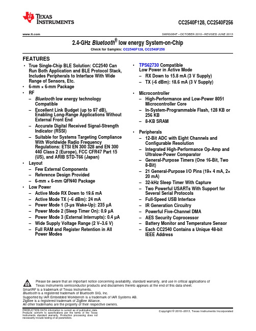
CC2540F128,CC2540F256 SWRS084F–OCTOBER2010–REVISED JUNE20132.4-GHz Bluetooth®low energy System-on-ChipCheck for Samples:CC2540F128,CC2540F256FEATURES•TPS62730Compatible•True Single-Chip BLE Solution:CC2540CanLow Power in Active Mode Run Both Application and BLE Protocol Stack,Includes Peripherals to Interface With Wide–RX Down to15.8mA(3V Supply)Range of Sensors,Etc.–TX(-6dBm):18.6mA(3V Supply)•6-mm×6-mm Package•RF•Microcontroller–Bluetooth low energy technology–High-Performance and Low-Power8051 Compatible Microcontroller Core–Excellent Link Budget(up to97dB),–In-System-Programmable Flash,128KB or Enabling Long-Range Applications Without256KBExternal Front End–8-KB SRAM–Accurate Digital Received Signal-StrengthIndicator(RSSI)•Peripherals–Suitable for Systems Targeting Compliance–12-Bit ADC with Eight Channels and With Worldwide Radio Frequency Configurable ResolutionRegulations:ETSI EN300328and EN300–Integrated High-Performance Op-Amp and 440Class2(Europe),FCC CFR47Part15Ultralow-Power Comparator (US),and ARIB STD-T66(Japan)–General-Purpose Timers(One16-Bit,Two •Layout8-Bit)–Few External Components–21General-Purpose I/O Pins(19×4mA,2×–Reference Design Provided20mA)–6-mm×6-mm QFN40Package–32-kHz Sleep Timer With Capture•Low Power–Two Powerful USARTs With Support for –Active Mode RX Down to19.6mA Several Serial Protocols–Active Mode TX(–6dBm):24mA–Full-Speed USB Interface–Power Mode1(3-μs Wake-Up):235μA–IR Generation Circuitry–Power Mode2(Sleep Timer On):0.9μA–Powerful Five-Channel DMA–Power Mode3(External Interrupts):0.4μA–AES Security Coprocessor–Wide Supply Voltage Range(2V–3.6V)–Battery Monitor and Temperature Sensor –Full RAM and Register Retention in All–Each CC2540Contains a Unique48-bit Power Modes IEEE AddressPlease be aware that an important notice concerning availability,standard warranty,and use in critical applications ofTexas Instruments semiconductor products and disclaimers thereto appears at the end of this data sheet.SmartRF is a trademark of Texas Instruments.Bluetooth is a registered trademark of Bluetooth SIG,Inc.Supported by IAR Embedded Workbench is a trademark of IAR Systems AB.ZigBee is a registered trademark of ZigBee Alliance.All other trademarks are the property of their respective owners.PRODUCTION DATA information is current as of publication date.Copyright©2010–2013,Texas Instruments Incorporated Products conform to specifications per the terms of the TexasCC2540F128,CC2540F256SWRS084F–OCTOBER2010–REVISED SOFTWARE FEATURES APPLICATIONS•Bluetooth v4.0Compliant Protocol Stack for• 2.4-GHz Bluetooth low energy Systems Single-Mode BLE Solution•Mobile Phone Accessories–Complete Power-Optimized Stack,•Sports and Leisure Equipment Including Controller and Host•Consumer Electronics–GAP–Central,Peripheral,Observer,or•Human Interface Devices(Keyboard,Mouse, Broadcaster(Including Combination Remote Control)Roles)•USB Dongles–ATT/GATT–Client and Server•Health Care and Medical–SMP–AES-128Encryption andDecryption CC2540WITH TPS62730–L2CAP•TPS62730is a2MHz Step Down Converter –Sample Applications and Profiles with Bypass Mode–Generic Applications for GAP Central•Extends Battery Lifetime by up to20% and Peripheral Roles•Reduced Current in TX and RX –Proximity,Accelerometer,Simple Keys,•30nA Bypass Mode Current to Support Low and Battery GATT ServicesPower Modes–Multiple Configuration options•RF Performance Unchanged –Single-Chip Configuration,Allowing•Small Package Allows for Small Solution Size Application to Run on CC2540•CC2540Controllable–Network Processor Interface forApplications Running on an ExternalMicrocontroller–BTool–Windows PC Application forEvaluation,Development,and Test•Development Tools–CC2540Mini Development Kit–SmartRF™Software–Supported by IAR Embedded Workbench™Software for8051DESCRIPTIONThe CC2540is a cost-effective,low-power,true system-on-chip(SoC)for Bluetooth low energy applications.It enables robust BLE master or slave nodes to be built with very low total bill-of-material costs.The CC2540 combines an excellent RF transceiver with an industry-standard enhanced8051MCU,in-system programmable flash memory,8-KB RAM,and many other powerful supporting features and peripherals.The CC2540is suitable for systems where very low power consumption is required.Very low-power sleep modes are available.Short transition times between operating modes further enable low power consumption.The CC2540comes in two different versions:CC2540F128/F256,with128and256KB of flash memory, respectively.Combined with the Bluetooth low energy protocol stack from Texas Instruments,the CC2540F128/F256forms the market’s most flexible and cost-effective single-mode Bluetooth low energy solution.2Submit Documentation Feedback Copyright©2010–2013,Texas Instruments IncorporatedRESET_N XOSC_Q2XOSC_Q1P2_4P1_7P0_7P2_3P1_6P0_6P2_2P1_5P0_5P1_2P0_2P2_1P1_4P0_4P1_1P0_1P2_0P1_3P0_3P1_0P0_0USB_N USB_PCC2540F128,CC2540F256SWRS084F –OCTOBER 2010–REVISED JUNE 2013Copyright ©2010–2013,Texas Instruments Incorporated Submit Documentation Feedback 3CC2540F128,CC2540F256SWRS084F–OCTOBER2010–REVISED This integrated circuit can be damaged by ESD.Texas Instruments recommends that all integrated circuits be handled withappropriate precautions.Failure to observe proper handling and installation procedures can cause damage.ESD damage can range from subtle performance degradation to complete device failure.Precision integrated circuits may be more susceptible to damage because very small parametric changes could cause the device not to meet its published specifications.ABSOLUTE MAXIMUM RATINGS(1)MIN MAX UNIT Supply voltage All supply pins must have the same voltage–0.3 3.9V–0.3VDD+0.3,Voltage on any digital pin V≤3.9Input RF level10dBm Storage temperature range–40125°CAll pads,according to human-body model,JEDEC STD22,method A1142kV ESD(2)According to charged-device model,JEDEC STD22,method C101750V (1)Stresses beyond those listed under Absolute Maximum Ratings may cause permanent damage to the device.These are stress ratingsonly,and functional operation of the device at these or any other conditions beyond those indicated under Recommended Operating Conditions is not implied.Exposure to absolute-maximum-rated conditions for extended periods may affect device reliability.(2)CAUTION:ESD sensitive device.Precautions should be used when handing the device in order to prevent permanent damage. RECOMMENDED OPERATING CONDITIONSMIN MAX UNIT Operating ambient temperature range,T A–4085°C Operating supply voltage2 3.6V ELECTRICAL CHARACTERISTICSMeasured on Texas Instruments CC2540EM reference design with T A=25°C and VDD=3VPARAMETER TEST CONDITIONS MIN TYP MAX UNITPower mode1.Digital regulator on;16-MHz RCOSC and32-MHz crystal oscillator off;32.768-kHz XOSC,POR,BOD and235sleep timer active;RAM and register retentionPower mode2.Digital regulator off;16-MHz RCOSC and32-µAMHz crystal oscillator off;32.768-kHz XOSC,POR,and sleep0.9I core Core current consumption timer active;RAM and register retentionPower mode3.Digital regulator off;no clocks;POR active;0.4RAM and register retentionLow MCU activity:32-MHz XOSC running.No radio or6.7mAperipherals.No flash access,no RAM access.Timer1.Timer running,32-MHz XOSC used90μATimer2.Timer running,32-MHz XOSC used90μA Peripheral current consumption Timer3.Timer running,32-MHz XOSC used60μA I peri(Adds to core current I core for eachTimer4.Timer running,32-MHz XOSC used70μA peripheral unit activated)Sleep timer,including32.753-kHz RCOSC0.6μAADC,when converting 1.2mA 4Submit Documentation Feedback Copyright©2010–2013,Texas Instruments IncorporatedCC2540F128,CC2540F256 SWRS084F–OCTOBER2010–REVISED JUNE2013GENERAL CHARACTERISTICSMeasured on Texas Instruments CC2540EM reference design with T A=25°C and VDD=3VPARAMETER TEST CONDITIONS MIN TYP MAX UNIT WAKE-UP AND TIMINGDigital regulator on,16-MHz RCOSC and32-MHz crystalPower mode1→Active4μsoscillator off.Start-up of16-MHz RCOSCDigital regulator off,16-MHz RCOSC and32-MHz crystalPower mode2or3→Active120μsoscillator off.Start-up of regulator and16-MHz RCOSCCrystal ESR=16Ω.Initially running on16-MHz RCOSC,410μswith32-MHz XOSC OFFActive→TX or RXWith32-MHz XOSC initially on160μsRX/TX turnaround150μs RADIO PARTRF frequency range Programmable in2-MHz steps24022480MHz Data rate and modulation format1Mbps,GFSK,250kHz deviationRF RECEIVE SECTIONMeasured on Texas Instruments CC2540EM reference design with T A=25°C,VDD=3V,f c=2440MHz1Mbps,GFSK,250-kHz deviation,Bluetooth low energy mode,and0.1%BER(1)PARAMETER TEST CONDITIONS MIN TYP MAX UNIT Receiver sensitivity(2)High-gain mode–93dBm Receiver sensitivity(2)Standard mode–87dBm Saturation(3)6dBm Co-channel rejection(3)–5dB Adjacent-channel rejection(3)±1MHz–5dB Alternate-channel rejection(3)±2MHz30dB Blocking(3)–30dBm Frequency error tolerance(4)Including both initial tolerance and drift–250250kHz Symbol rate error tolerance(5)–8080ppmConducted measurement with a50-Ωsingle-ended load.Spurious emission.Only largest spuriousComplies with EN300328,EN300440class2,FCC CFR47,–75dBm emission stated within each band.Part15and ARIB STD-T-66RX mode,standard mode,no peripherals active,low MCU19.6activity,MCU at250kHzCurrent consumption mARX mode,high-gain mode,no peripherals active,low MCU22.1activity,MCU at250kHz(1)0.1%BER maps to30.8%PER(2)The receiver sensitivity setting is programmable using a TI BLE stack vendor-specific API command.The default value is standardmode.(3)Results based on standard gain mode(4)Difference between center frequency of the received RF signal and local oscillator frequency(5)Difference between incoming symbol rate and the internally generated symbol rateCopyright©2010–2013,Texas Instruments Incorporated Submit Documentation Feedback5CC2540F128,CC2540F256SWRS084F–OCTOBER2010–REVISED RF TRANSMIT SECTIONMeasured on Texas Instruments CC2540EM reference design with T A=25°C,VDD=3V and f c=2440MHz PARAMETER TEST CONDITIONS MIN TYP MAX UNITDelivered to a single-ended50-Ωload through a balun using4maximum recommended output power settingOutput power dBmDelivered to a single-ended50-Ωload through a balun using minimum–23recommended output power settingProgrammable output power Delivered to a single-ended50Ωload through a balun27dB rangeConducted measurement with a50-Ωsingle-ended pliesSpurious emissions with EN300328,EN300440class2,FCC CFR47,Part15and ARIB–41dBmSTD-T-66(1)TX mode,–23-dBm output power,no peripherals active,low MCU21.1activity,MCU at250kHzTX mode,–6-dBm output power,no peripherals active,low MCU23.8activity,MCU at250kHzCurrent consumption mATX mode,0-dBm output power,no peripherals active,low MCU27activity,MCU at250kHzTX mode,4-dBm output power,no peripherals active,low MCU31.6activity,MCU at250kHzDifferential impedance as seen from the RF port(RF_P and RF_N)Optimum load impedance70+j30Ωtoward the antenna(1)Designs with antenna connectors that require conducted ETSI compliance at64MHz should insert an LC resonator in front of theantenna e a1.6-nH inductor in parallel with a1.8-pF capacitor.Connect both from the signal trace to a good RF ground. CURRENT CONSUMPTION WITH TPS62730Measured on Texas Instruments CC2540TPS62730EM reference design with T A=25°C,VDD=3V,and f c=2440MHZ.1Mbps,GFSK,250kHz deviation,Bluetooth™low energy mode,1%BER(1)PARAMETER TEST CONDITIONS MIN TYP MAX UNITRX mode,standard mode,no peripherals active,low MCU activity,MCU at115.8MHZRX mode,high-gain mode,no peripherals active,low MCU activity,MCU at117.8MHZTX mode,-23dBm output power,no peripherals active,low MCU activity,16.5MCU at1MHZCurrent Consumption mA TX mode,-6dBm output power,no peripherals active,low MCU activity,18.6MCU at1MHZTX mode,0dBm output power,no peripherals active,low MCU activity,21MCU at1MHZTX mode,4dBm output power,no peripherals active,low MCU activity,24.6MCU at1MHZ(1)0.1%BER maps to30.8%PER6Submit Documentation Feedback Copyright©2010–2013,Texas Instruments IncorporatedCC2540F128,CC2540F256 SWRS084F–OCTOBER2010–REVISED JUNE201332-MHz CRYSTAL OSCILLATORMeasured on Texas Instruments CC2540EM reference design with T A=25°C and VDD=3VPARAMETER TEST CONDITIONS MIN TYP MAX UNIT Crystal frequency32MHz Crystal frequency accuracy–4040ppm requirement(1)ESR Equivalent series resistance660ΩC0Crystal shunt capacitance17pFC L Crystal load capacitance1016pFStart-up time0.25msThe crystal oscillator must be in power down for aguard time before it is used again.ThisPower-down guard time requirement is valid for all modes of operation.The3msneed for power-down guard time can vary withcrystal type and load.(1)Including aging and temperature dependency,as specified by[1]32.768-kHz CRYSTAL OSCILLATORMeasured on Texas Instruments CC2540EM reference design with T A=25°C and VDD=3VPARAMETER TEST CONDITIONS MIN TYP MAX UNIT Crystal frequency32.768kHzCrystal frequency accuracy–4040ppm requirement(1)ESR Equivalent series resistance40130kΩC0Crystal shunt capacitance0.92pFC L Crystal load capacitance1216pFStart-up time0.4s (1)Including aging and temperature dependency,as specified by[1]32-kHz RC OSCILLATORMeasured on Texas Instruments CC2540EM reference design with Tω=25°C and VDD=3V.PARAMETER TEST CONDITIONS MIN TYP MAX UNIT Calibrated frequency(1)32.753kHz Frequency accuracy after calibration±0.2%Temperature coefficient(2)0.4%/°C Supply-voltage coefficient(3)3%/V Calibration time(4)2ms(1)The calibrated32-kHz RC oscillator frequency is the32-MHz XTAL frequency divided by977.(2)Frequency drift when temperature changes after calibration(3)Frequency drift when supply voltage changes after calibration(4)When the32-kHz RC oscillator is enabled,it is calibrated when a switch from the16-MHz RC oscillator to the32-MHz crystal oscillatoris performed while SLEEPCMD.OSC32K_CALDIS is set to0.Copyright©2010–2013,Texas Instruments Incorporated Submit Documentation Feedback7CC2540F128,CC2540F256SWRS084F–OCTOBER2010–REVISED 16-MHz RC OSCILLATORMeasured on Texas Instruments CC2540EM reference design with T A=25°C and VDD=3VPARAMETER TEST CONDITIONS MIN TYP MAX UNIT Frequency(1)16MHz Uncalibrated frequency accuracy±18%Calibrated frequency accuracy±0.6%Start-up time10μs Initial calibration time(2)50μs(1)The calibrated16-MHz RC oscillator frequency is the32-MHz XTAL frequency divided by2.(2)When the16-MHz RC oscillator is enabled,it is calibrated when a switch from the16-MHz RC oscillator to the32-MHz crystal oscillatoris performed while SLEEPCMD.OSC_PD is set to0.RSSI CHARACTERISTICSMeasured on Texas Instruments CC2540EM reference design with T A=25°C and VDD=3VPARAMETER TEST CONDITIONS MIN TYP MAX UNITHigh-gain mode–99to–44Useful RSSI range(1)dBmStandard mode–90to–35Absolute uncalibrated RSSI accuracy(1)High-gain mode±4dB Step size(LSB value)1dB (1)Assuming CC2540EM reference design.Other RF designs give an offset from the reported value.FREQUENCY SYNTHESIZER CHARACTERISTICSMeasured on Texas Instruments CC2540EM reference design with T A=25°C,VDD=3V and f c=2440MHz PARAMETER TEST CONDITIONS MIN TYP MAX UNITAt±1-MHz offset from carrier–109Phase noise,unmodulatedAt±3-MHz offset from carrier–112dBc/Hz carrierAt±5-MHz offset from carrier–119ANALOG TEMPERATURE SENSORMeasured on Texas Instruments CC2540EM reference design with T A=25°C and VDD=3VPARAMETER TEST CONDITIONS MIN TYP MAX UNIT Output148012-bit Temperature coefficient 4.5/1°C Voltage coefficient1/0.1VMeasured using integrated ADC,internal band-gap voltagereference,and maximum resolutionInitial accuracy without calibration±10°C Accuracy using1-point calibration±5°C Current consumption when enabled0.5mA8Submit Documentation Feedback Copyright©2010–2013,Texas Instruments IncorporatedCC2540F128,CC2540F256 SWRS084F–OCTOBER2010–REVISED JUNE2013OP-AMP CHARACTERISTICST A=25°C,VDD=3V,.All measurement results are obtained using the CC2540reference designs post-calibration.PARAMETER TEST CONDITIONS MIN TYP MAX UNIT Chopping Configuration,Register APCFG=0x07,OPAMPMC=0x03,OPAMPC=0x01Output maximum voltage VDD–0.1VOutput minimum voltage0.1VOpen-loop gain108dBGain-bandwidth product2MHzSlew rate 2.6V/μsInput maximum voltage VDD VIntput minimum voltage0mVInput offset voltage40μV CMRR Common-mode rejection ratio90dB Supply current0.4mAf=0.01Hz to1Hz 1.1 Input noise voltage nV/√(Hz)f=0.1Hz to10Hz 1.7Non-Chopping Configuration,Register APCFG=0x07,OPAMPMC=0x00,OPAMPC=0x01Output maximum voltage VDD–0.1VOutput minimum voltage0.1VOpen-loop gain108dBGain-bandwidth product2MHzSlew rate 2.6V/μsInput maximum voltage VDD VIntput minimum voltage0mVInput offset voltage 3.2mV CMRR Common-mode rejection ratio90dB Supply current0.4mAf=0.01Hz to1Hz60 Input noise voltage nV/√(Hz)f=0.1Hz to10Hz65 COMPARATOR CHARACTERISTICST A=25°C,VDD=3V.All measurement results are obtained using the CC2540reference designs,post-calibration.PARAMETER TEST CONDITIONS MIN TYP MAX UNIT Common-mode maximum voltage VDD VCommon-mode minimum voltage–0.3Input offset voltage1mVOffset vs temperature16µV/°COffset vs operating voltage4mV/VSupply current230nAHysteresis0.15mV Copyright©2010–2013,Texas Instruments Incorporated Submit Documentation Feedback9CC2540F128,CC2540F256SWRS084F–OCTOBER2010–REVISED ADC CHARACTERISTICST A=25°C and VDD=3VPARAMETER TEST CONDITIONS MIN TYP MAX UNIT Input voltage VDD is voltage on AVDD5pin0VDD VExternal reference voltage VDD is voltage on AVDD5pin0VDD VExternal reference voltage differential VDD is voltage on AVDD5pin0VDD VInput resistance,signal Simulated using4-MHz clock speed197kΩFull-scale signal(1)Peak-to-peak,defines0dBFS 2.97VSingle-ended input,7-bit setting 5.7Single-ended input,9-bit setting7.5Single-ended input,10-bit setting9.3Single-ended input,12-bit setting10.3Differential input,7-bit setting 6.5ENOB(1)Effective number of bits bitsDifferential input,9-bit setting8.3Differential input,10-bit setting10Differential input,12-bit setting11.510-bit setting,clocked by RCOSC9.712-bit setting,clocked by RCOSC10.9 Useful power bandwidth7-bit setting,both single and differential0–20kHzSingle ended input,12-bit setting,–6–75.2dBFS(1)THD Total harmonic distortion dBDifferential input,12-bit setting,–6–86.6dBFS(1)Single-ended input,12-bit setting(1)70.2Differential input,12-bit setting(1)79.3Single-ended input,12-bit setting,–6Signal to nonharmonic ratio dB78.8dBFS(1)Differential input,12-bit setting,–688.9dBFS(1)Differential input,12-bit setting,1-kHzCMRR Common-mode rejection ratio>84dBsine(0dBFS),limited by ADC resolutionSingle ended input,12-bit setting,1-kHzCrosstalk>84dBsine(0dBFS),limited by ADC resolutionOffset Midscale–3mVGain error0.68%12-bit setting,mean(1)0.05DNL Differential nonlinearity LSB12-bit setting,maximum(1)0.912-bit setting,mean(1) 4.612-bit setting,maximum(1)13.3INL Integral nonlinearity LSB12-bit setting,mean,clocked by RCOSC1012-bit setting,max,clocked by RCOSC29Single ended input,7-bit setting(1)35.4Single ended input,9-bit setting(1)46.8Single ended input,10-bit setting(1)57.5Single ended input,12-bit setting(1)66.6SINADSignal-to-noise-and-distortion dB (–THD+N)Differential input,7-bit setting(1)40.7Differential input,9-bit setting(1)51.6Differential input,10-bit setting(1)61.8Differential input,12-bit setting(1)70.8(1)Measured with300-Hz sine-wave input and VDD as reference.10Submit Documentation Feedback Copyright©2010–2013,Texas Instruments IncorporatedRESETADC CHARACTERISTICS(continued)T A=25°C and VDD=3VPARAMETER TEST CONDITIONS MIN TYP MAX UNIT7-bit setting209-bit setting36 Conversion timeμs10-bit setting6812-bit setting132 Power consumption 1.2mAInternal reference VDD coefficient4mV/VInternal reference temperature coefficient0.4mV/10°CInternal reference voltage 1.24V CONTROL INPUT AC CHARACTERISTICST A=–40°C to85°C,VDD=2V to3.6V.PARAMETER TEST CONDITIONS MIN TYP MAX UNITThe undivided system clock is32MHz when crystal oscillator is used.System clock,f SYSCLKThe undivided system clock is16MHz when calibrated16-MHz RC1632MHz t SYSCLK=1/f SYSCLK oscillator is used.See item1,Figure1.This is the shortest pulse that is recognized asa complete reset pin request.Note that shorter pulses may beRESET_N low duration1µs recognized but do not lead to complete reset of all modules within thechip.See item2,Figure1.This is the shortest pulse that is recognized asInterrupt pulse duration20ns an interrupt request.Figure1.Control Input AC CharacteristicsSCKSSNMOSIMISOT0478-01SPI AC CHARACTERISTICST A =–40°C to 85°C,VDD =2V to 3.6VPARAMETERTEST CONDITIONSMIN TYP MAXUNIT Master,RX and TX 250t 1SCK period nsSlave,RX and TX 250SCK duty cycleMaster 50%Master 63t 2SSN low to SCK ns Slave 63Master 63t 3SCK to SSN high ns Slave63t 4MOSI early out Master,load =10pF 7ns t 5MOSI late out Master,load =10pF 10ns t 6MISO setup Master 90ns t 7MISO hold Master 10ns SCK duty cycle Slave 50%ns t 10MOSI setup Slave 35ns t 11MOSI hold Slave10ns t 9MISO late outSlave,load =10pF 95nsMaster,TX only8Master,RX and TX 4Operating frequencyMHzSlave,RX only 8Slave,RX and TX4Figure 2.SPI Master AC CharacteristicsT0479-01SCKSSNMOSIMISOFigure 3.SPI Slave AC CharacteristicsRESET _NDEBUG _CLKP2_2T0437-01DEBUG _CLKP2_2T0436-01DEBUG INTERFACE AC CHARACTERISTICST A =–40°C to 85°C,VDD =2V to 3.6VPARAMETERTEST CONDITIONS MIN TYP MAX UNIT f clk_dbg Debug clock frequency (see Figure 4)12MHz t 1Allowed high pulse on clock (see Figure 4)35ns t 2Allowed low pulse on clock (see Figure 4)35ns EXT_RESET_N low to first falling edge on debug t 3167ns clock (see Figure 6)Falling edge on clock to EXT_RESET_N high (see t 483ns Figure 6)EXT_RESET_N high to first debug command (see t 583ns Figure 6)t 6Debug data setup (see Figure 5)2ns t 7Debug data hold (see Figure 5)4nst 8Clock-to-data delay (see Figure 5)Load =10pF30nsFigure 4.Debug Clock –Basic TimingFigure 5.Debug Enable TimingDEBUG_CLKP2_2DEBUG_DATADEBUG_DATAT0438-02Figure6.Data Setup and Hold TimingTIMER INPUTS AC CHARACTERISTICST A=–40°C to85°C,VDD=2V to3.6VPARAMETER TEST CONDITIONS MIN TYP MAX UNIT Synchronizers determine the shortest input pulse that can beInput capture pulse duration recognized.The synchronizers operate at the current system clock rate 1.5t SYSCLK (16MHz or32MHz).DC CHARACTERISTICST A=25°C,VDD=3VPARAMETER TEST CONDITIONS MIN TYP MAX UNIT Logic-0input voltage0.5V Logic-1input voltage 2.5V Logic-0input current Input equals0V–5050nA Logic-1input current Input equals VDD–5050nAI/O-pin pullup and pulldown resistors20kΩLogic-0output voltage,4-mA pins Output load4mA0.5V Logic-1output voltage,4-mA pins Output load4mA 2.4VCC2540RHA Package (Top View)P 0_1R E S E T _NP 2_3 / X O S C 32K _Q 2A V D D 6DVDD_USBR_BIAS P 0_2P 0_0AVDD4P 0_3AVDD1P 0_4AVDD2P 0_5RF_N P 0_6RF_P P 0_7AVDD3XOSC_Q1P 1_0XOSC_Q2AVDD5P 2_2P 2_4 / X O S C 32K _Q 1USB_P P 2_1USB_N P 2_0DGND_USBP 1_7P1_5P 1_6P1_4D V D D 1P1_3P1_1D C O U P LP1_2DVDD2P0076-05DEVICE INFORMATIONPIN DESCRIPTIONSThe CC2540pinout is shown in Figure 7and a short description of the pins follows.NOTE:The exposed ground pad must be connected to a solid ground plane,as this is the ground connection for the chip.Figure 7.Pinout Top ViewPIN DESCRIPTIONSPIN NAME PIN PIN TYPE DESCRIPTIONAVDD128Power(analog)2-V–3.6-V analog power-supply connectionAVDD227Power(analog)2-V–3.6-V analog power-supply connectionAVDD324Power(analog)2-V–3.6-V analog power-supply connectionAVDD429Power(analog)2-V–3.6-V analog power-supply connectionAVDD521Power(analog)2-V–3.6-V analog power-supply connectionAVDD631Power(analog)2-V–3.6-V analog power-supply connectionDCOUPL40Power(digital) 1.8-V digital power-supply decoupling.Do not use for supplying external circuits. DGND_USB1Ground pin Connect to GNDDVDD_USB4Power(digital)2-V–3.6-V digital power-supply connectionDVDD139Power(digital)2-V–3.6-V digital power-supply connectionDVDD210Power(digital)2-V–3.6-V digital power-supply connectionGND—Ground The ground pad must be connected to a solid ground plane.P0_019Digital I/O Port0.0P0_118Digital I/O Port0.1P0_217Digital I/O Port0.2P0_316Digital I/O Port0.3P0_415Digital I/O Port0.4P0_514Digital I/O Port0.5P0_613Digital I/O Port0.6P0_712Digital I/O Port0.7P1_011Digital I/O Port1.0–20-mA drive capabilityP1_19Digital I/O Port1.1–20-mA drive capabilityP1_28Digital I/O Port1.2P1_37Digital I/O Port1.3P1_46Digital I/O Port1.4P1_55Digital I/O Port1.5P1_638Digital I/O Port1.6P1_737Digital I/O Port1.7P2_036Digital I/O Port2.0P2_135Digital I/O Port2.1P2_234Digital I/O Port2.2P2_3/33Digital I/O,Port2.3/32.768kHz XOSCXOSC32K_Q2Analog I/OP2_4/32Digital I/O,Port2.4/32.768kHz XOSCXOSC32K_Q1Analog I/ORBIAS30Analog I/O External precision bias resistor for reference currentRESET_N20Digital input Reset,active-lowRF_N26RF I/O Negative RF input signal to LNA during RXNegative RF output signal from PA during TXRF_P25RF I/O Positive RF input signal to LNA during RXPositive RF output signal from PA during TXUSB_N3Digital I/O USB NUSB_P2Digital I/O USB PXOSC_Q122Analog I/O32-MHz crystal oscillator pin1or external-clock inputXOSC_Q223Analog I/O32-MHz crystal oscillator pin2RESET_N XOSC_Q2XOSC_Q1P2_4P1_7P0_7P2_3P1_6P0_6P2_2P1_5P0_5P1_2P0_2P2_1P1_4P0_4P1_1P0_1P2_0P1_3P0_3P1_0P0_0USB_N USB_PBLOCK DIAGRAMA block diagram of the CC2540is shown in Figure 8.The modules can be roughly divided into one of three categories:CPU-related modules;modules related to power,test,and clock distribution;and radio-related modules.In the following subsections,a short description of each module is given.Figure 2540Block DiagramBLOCK DESCRIPTIONSCPU and MemoryThe8051CPU core is a single-cycle8051-compatible core.It has three different memory access busses(SFR, DATA,and CODE/XDATA),a debug interface,and an18-input extended interrupt unit.The memory arbiter is at the heart of the system,as it connects the CPU and DMA controller with the physical memories and all peripherals through the SFR bus.The memory arbiter has four memory-access points,access of which can map to one of three physical memories:an SRAM,flash memory,and XREG/SFR registers.It is responsible for performing arbitration and sequencing between simultaneous memory accesses to the same physical memory.The SFR bus is drawn conceptually in Figure8as a common bus that connects all hardware peripherals to the memory arbiter.The SFR bus in the block diagram also provides access to the radio registers in the radio register bank,even though these are indeed mapped into XDATA memory space.The8-KB SRAM maps to the DATA memory space and to parts of the XDATA memory spaces.The SRAM is an ultralow-power SRAM that retains its contents even when the digital part is powered off(power modes2and 3).The128/256KB flash block provides in-circuit programmable non-volatile program memory for the device,and maps into the CODE and XDATA memory spaces.PeripheralsWriting to the flash block is performed through a flash controller that allows page-wise erasure and4-bytewise programming.See User Guide for details on the flash controller.A versatile five-channel DMA controller is available in the system,accesses memory using the XDATA memory space,and thus has access to all physical memories.Each channel(trigger,priority,transfer mode,addressing mode,source and destination pointers,and transfer count)is configured with DMA descriptors that can be located anywhere in memory.Many of the hardware peripherals(AES core,flash controller,USARTs,timers, ADC interface,etc.)can be used with the DMA controller for efficient operation by performing data transfers between a single SFR or XREG address and flash/SRAM.Each CC2540contains a unique48-bit IEEE address that can be used as the public device address for a Bluetooth device.Designers are free to use this address,or provide their own,as described in the Bluetooth specfication.The interrupt controller services a total of18interrupt sources,divided into six interrupt groups,each of which is associated with one of four interrupt priorities.I/O and sleep timer interrupt requests are serviced even if the device is in a sleep mode(power modes1and2)by bringing the CC2540back to the active mode.The debug interface implements a proprietary two-wire serial interface that is used for in-circuit debugging. Through this debug interface,it is possible to erase or program the entire flash memory,control which oscillators are enabled,stop and start execution of the user program,execute instructions on the8051core,set code breakpoints,and single-step through instructions in the ing these techniques,it is possible to perform in-circuit debugging and external flash programming elegantly.The I/O controller is responsible for all general-purpose I/O pins.The CPU can configure whether peripheral modules control certain pins or whether they are under software control,and if so,whether each pin is configured as an input or output and if a pullup or pulldown resistor in the pad is connected.Each peripheral that connects to the I/O pins can choose between two different I/O pin locations to ensure flexibility in various applications.The sleep timer is an ultralow-power timer that can either use an external32.768-kHz crystal oscillator or an internal32.753-kHz RC oscillator.The sleep timer runs continuously in all operating modes except power mode 3.Typical applications of this timer are as a real-time counter or as a wake-up timer to get out of power modes1 or2.A built-in watchdog timer allows the CC2540to reset itself if the firmware hangs.When enabled by software, the watchdog timer must be cleared periodically;otherwise,it resets the device when it times out.。
cc2540
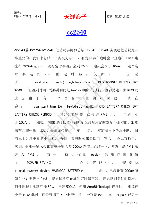
cc2540cc2540篇1:cc2540 cc2541 低功耗实测和总结CC2541 CC2540 实现超低功耗是非常重要的:我们来总结一下实现方法:1,有定时器在跑时会一直跑在PM2电流在300uA左右。
没有定时器跑后会到PM3,电流会少于10uA。
这个定时器是指osal的定时器,例如:启动了osal_start_timerEx( keyfobapp_TaskID, KFD_TOGGLE_BUZZER_EVT, 2000 );但没到时间:需要说明的是keyfob中的低功耗一直都是进不去PM3的,这是由于有一个查询电量的定时器一直在跑:osal_start_timerEx( keyfobapp_TaskID, KFD_BATTERY_CHECK_EVT, BATTERY_CHECK_PERIOD );把它注释掉就会进PM3了。
电流小于10uA 。
因此,如果你想低功耗到但是又想启用定时器是不现实的。
2,如果有外部中断,比如开关量如按键,一定,一定,一定需要用下降沿中断,目前我上升沿中断调不出来,并且,常态时如果是低电平输入,会比较耗电。
实测,低电平输入会比高电平输入多200uA左右。
总结一下:常态下是PM1要进入PM2,首先,确认你的option的编译宏设置了POWER_SAVING然后代码中,需要执行osal_pwrmgr_device( PWRMGR_BATTERY );即可,电流还有200uA呀,怎么办?要进入Pm3,需要你没有osal的定时器在跑。
详见我们提供的例程。
附件例程上电就广播30s,电流500uA,使用AmoBleTool.apk连接后,电流在小于10uA此时,已经开通了3个电平中断,分别是P0.0,p0.1与p0.4任意一个中断产生,AmoBleTool.apk都键收到数据,请注意观察。
电流测试方法为在供电电路上串一个电流表即可。
cc2540篇2:Ti CC2540蓝牙模块学习笔记整理Ti CC2540蓝牙模块学习笔记整理接触CC2540几天,终于有了初步的理解,现将笔记整理如下,只是皮毛,如有错误,还请指正,还有好多没闹明白的地方,以后应该还会继续向里面更新~一、整体1.TI的蓝牙平台支持2种协议栈/应用配置:单一设备配置、网络处理器配置2.协议栈最顶层2个通用profile:GAP 通用访问配置文件层Generic Access ProfileGATT 通用属性配置文件层Generic Attribute Profile3. GAP:处理设备的接入方式及接入过程:①设备发现②链路建立③链路终止④启动安全功能⑤设备配置(主要是连接参数配置)GATT:完成服务器与客户端之间通信的相关子过程4.BLE支持40个信道的跳频机制,其中3个通道用于Advertise,剩下的用于数据通信5.OS抽象层:疑问如何配置一个新的任务,任务的优先级,事件触发机制,消息的传递 6.主要用于实现的是2个代码文件:OSAL_SimpleBLEPeripheral.c 任务回调函数数据的定义和任务初始化函数定义作为OSAL的外部全局变量SimpleBLEPeripheral.c BLE应用程序的实现代码,该源文件调用一系列的API函数,完成复杂的蓝牙协议通过const pTaskEventHandleFn tasksArr[] 数组来存储要调用的函数simpleBLEPeripheral.h 一些常量的定义,和蓝牙应用程序任务初始化和任务回调函数声明。
CC2540、BLE、低功耗蓝牙4.0、透传模块-硬件手册
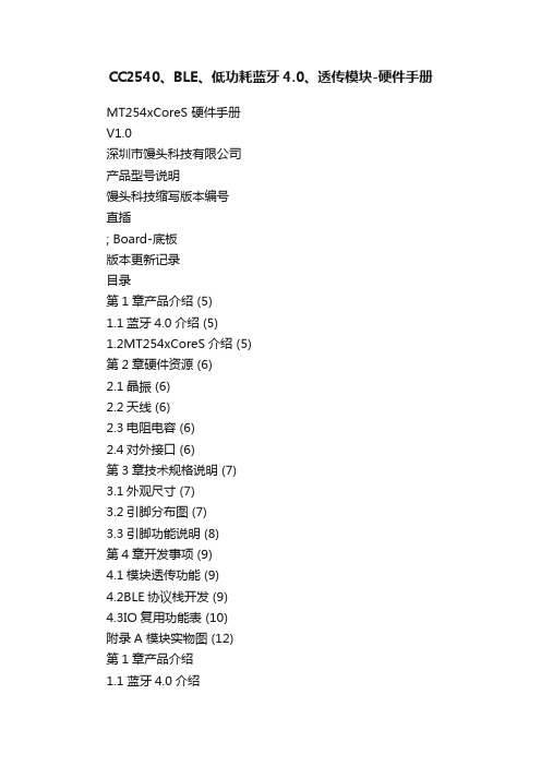
CC2540、BLE、低功耗蓝牙4.0、透传模块-硬件手册MT254xCoreS 硬件手册V1.0深圳市馒头科技有限公司产品型号说明馒头科技缩写版本编号直插; Board-底板版本更新记录目录第1章产品介绍 (5)1.1蓝牙4.0介绍 (5)1.2MT254xCoreS介绍 (5)第2章硬件资源 (6)2.1晶振 (6)2.2天线 (6)2.3电阻电容 (6)2.4对外接口 (6)第3章技术规格说明 (7)3.1外观尺寸 (7)3.2引脚分布图 (7)3.3引脚功能说明 (8)第4章开发事项 (9)4.1模块透传功能 (9)4.2BLE协议栈开发 (9)4.3IO复用功能表 (10)附录A 模块实物图 (12)第1章产品介绍1.1 蓝牙4.0介绍蓝牙4.0是2012年最新蓝牙版本,是3.0的升级版本;较3.0版本更省电、成本低、3毫秒低延迟、超长有效连接距离、AES-128加密等;通常用在蓝牙耳机、蓝牙音箱等设备上。
蓝牙4.0最重要的特性是省电,极低的运行和待机功耗可以使一粒纽扣电池连续工作数年之久。
此外,低成本和跨厂商互操作性,3毫秒低延迟、AES-128加密等诸多特色,可以用于计步器、心律监视器、智能仪表、传感器物联网等众多领域,大大扩展蓝牙技术的应用范围。
蓝牙4.0已经走向了商用,在最新款的Xperia Z、Galaxy S3、S4、Note2、SurfaceRT、iPhone 5、iPhone 4S、魅族MX3、Moto Droid Razr、HTC One X、小米手机2、The New iPad、iPad 4、MacBook Air、Macbook Pro,Nokia Lumia系列以及台商ACER AS3951系列/Getway NV57系列,ASUS UX21/31三星NOTE系列上都已应用了蓝牙4.0技术。
蓝牙4.0支持两种部署方式:双模式和单模式。
双模式中,低功耗蓝牙功能集成在现有的经典蓝牙控制器中,或再在现有经典蓝牙技术(2.1+EDR/3.0+HS)芯片上增加低功耗堆栈,整体架构基本不变,因此成本增加有限。
德州仪器的超节能的蓝牙芯片CC2540方案

德州仪器的超节能的蓝牙芯片CC2540方案Bluetooth Low Energy是标准组织Bluetooth SIG为应对来自其他低功耗无线标准竞争,新开发的超低功耗蓝牙传输标准。
CC2540 是一款高性价比,低功耗的片上系统(Soc)解决计划,适合蓝牙低耗能应用,它以低总体物料清单成本,建立矫健的网络节点成为可能。
基本特点:CC2540 包含一个精彩的工业标准的8051 内核的RF ,系统编程闪存记忆,8KB RAM 和其他功能强大的配套特征以及外设。
CC2540 适用于低功耗系统,超低的睡眠模式,以及运行模式的超低功耗的转换进一步实现了超低功耗。
CC2540 有2 中不同的版本:CC2540F128/F256 ,分离拥有128 和256KB 闪存记忆。
与TI 的蓝牙低功耗协议栈相衔接,CC2540F128/256 形成市场上最灵便,高性价比的单模式蓝牙低耗能解决计划。
CC2540 蓝牙低能耗片上系统:特性与优势单芯片器件:6 毫米 x 6 毫米封装中的集成型控制器、主机与应用可缩小物理尺寸,降低成本;基于闪存:器件固件可举行现场更新,数据可片上存储,从而可为开发商提高灵便性;TI 完整的解决计划:低功耗 RF IC、全面的单模式协议栈、配置文件软件以及应用支持;RF 性能:精彩的长距离链路预算(高达 +97 dB)以及与其它 2.4 GHz 器件的良好共存性;互操作性/兼容性:符合蓝牙规范 4.0 版标准的单模式 (CC2540) 与双模式器件(BlueLink 7.0 蓝牙/FM 单芯片解决计划、WiLink 7.0 WLAN//蓝牙/FM 单芯片解决计划以及 WiLink 6.0 WLAN/蓝牙/FM 单芯片解决计划)可实现全面的链路测试与开发。
计划特点:The CC2540 development kit provides a complete hardware第1页共2页。
CC2540:超节能蓝牙芯片方案

CC2540:超节能蓝牙芯片方案
佚名
【期刊名称】《世界电子元器件》
【年(卷),期】2013(000)003
【摘要】BluetoothLowEnergy是蓝牙标准组织BluetoothSlG为应对来自其他低功耗无线标准竞争,新开发的超低功耗蓝牙传输标准。
德州仪器的CC2540是一款高性价比、低功耗的片上系统(Soc)解决方案,适合蓝牙低耗能应用,它以低总体物料清单成本,建立强健的网络节点成为可能。
【总页数】2页(P19-20)
【正文语种】中文
【相关文献】
1.丹佛斯智能商超解决方案助力商超节能降本新常态--访丹佛斯商超及食品零售业能源管理解决方案销售总监朱朝辉 [J], 林雨晨
2.创新方案助力商超节能发展--访丹佛斯制冷与空调控制部食品零售业务市场经理倪莉 [J], 纤荷
3.CSR蓝牙芯片方案获Nokia第一款Bluetooth v2.0+EDR耳机采用 [J],
4.本土蓝牙芯片厂商的市场策略:锁定特定领域,提供特色解决方案 [J], 王莹
5.基于CSR蓝牙芯片(BC5MM)及SiRF(Discrete &SoC)的导航及车载电脑解决方案 [J],
因版权原因,仅展示原文概要,查看原文内容请购买。
TI低功耗蓝牙BLE4.0射频片上系统CC2540中文数据手册

Shenzhen RF-star Technology Co.,Ltd. TEL: 0755-86329829 FAX:0755-86329413
WISDOM FUTURE WIRELESS WORLD
智慧未来 无线世界
This integrated circuit can be damaged by ESD. Texas Instruments recommends that all integrated circuits be handled with appropriate precautions. Failure to observe proper handling and installation procedures can cause damage. ESD damage can range from subtle performance degradation to complete device failure. Precision integrated circuits may be more susceptible to damage because very small changes could cause the device not to meet its published specifications.
基于CC2540的蓝牙射频模块设计

V0 l - 2 6 No. 2
J u n . 2 0 1 3
基于 C C 2 5 4 0 的蓝牙射频模块设计
曹青春 ,刘 辉1 , 2
( 1 . 南海东软信息技术职业学院 计算机 系, 广东 佛 山 5 2 8 2 2 5 ;
2 . 华 南 师范大 学 物理 与 电信 工程 学院微 波 与天线 实验 室 , 广东 广州 5 1 0 0 0 6 ) 摘 要: 采 用T I 公 司C C 2 5 4 0 蓝 牙低 功耗 芯 片作 为核 心 器件 , 设计 了一种基 于蓝 牙 4 . 0 协议 的 无 线模 块 . 设计 给 出 了蓝 牙无线 通信 模 块 系统 硬件 框 架. 并根 据该 系统框 架设 计 了外 围 电路 、 射 频 阻抗 匹配 电路 以及 蓝 牙印 制倒 F天 线. 采 用 分 立 阻抗 器件 搭 建 阻抗 匹配 网络 以实现 蓝 牙模 块
F o s h a n 5 2 8 2 2 5 , C h i n a;
2 . A n t e n n a a n d Mi c r o w a v e L a b , S c n d T e l e c o m m u n i c a t i o s n E n g i n e e r i n g , S o u t h C h i n a
第2 6 卷第 2 期 2 0 1 3 年6 月
海 南 师范大 学学 报 ( 自然科 学 版 )
J o u r n a l o f H a i n a n N o r ma l U n i v e r s i t y ( N a t u r a l S c i e n c e )
CC 2 5 4 0 , i s d e s i g n e d i n t h i s p a p e r . T h e b l o c k d i a g r a m o f h a r d wa r e c i r c u i t f o r Bl u e t o o t h w i r e l e s s s y s t e m i s p r o p o s e d . T h e p e i r p h e r a l c i r c u i t ,i mp e d a n c e ma t c h i n g c i r c u i t a n d a mi n i a t u iz r e d I n v e ae d -F a n t e n n a a r e d e s i g n e d b a s e d o n t h e p r o — p o s e d L a me wo r k . Th e P in r t e d I n v e a e d - F a n t e n n a or f B l u e t o o t h i s mo d e l e d b y e l e c t r o ma g n e t i c s i mu l a t i o n s o f t wa r e o f
基于cc2540的蓝牙4.0物品标签识别系统

人工智能及识别技术本栏目责任编辑:唐一东基于CC2540的蓝牙4.0物品标签识别系统强孙源,廖家舟,何壮(成都理工大学信息科学与技术学院,四川成都610059)摘要:以TI 公司CC2540超低功耗蓝牙片上系统为核心器件,设计了一套内置BLE4.0协议物品标签自动识别与报警系统。
阐述了蓝牙无线通信物品标签识别的硬件框架及软件流程,该系统可与BLE4.0协议的物品标签进行无缝连接,围绕最小功耗设计,具有功耗低、小型化、可靠性好、生产成本低的特点。
关键词:CC2540;BLE4.0;超距离报警;天线及匹配电路;物品标签识别中图分类号:TP334文献标识码:A文章编号:1009-3044(2019)28-0213-02开放科学(资源服务)标识码(OSID ):Bluetooth 4.0Item Label Recognition System Based on CC2540QIANG Sun-yuan ,LIAO Jiao-zhou ,HE Zhuang(Chengdu University of Technology,Chengdu 610059,China)Abstract:With TI CC2540ultra-low power bluetooth chip system as the core device,a set of built-in BLE4.0protocol item label automatic identification and alarm system is designed.The hardware framework and software flow of Bluetooth wireless communica⁃tion item label recognition are described.The system seamlessly interfaces with the BLE4.0protocol item label and is designed around minimal power consumption,which has the characteristics of low power consumption,miniaturization,good reliability and low production cost.Key words:CC2540;BLE4.0;over distance alarm;antenna and matching circuit;item tag recognition1背景在日常生活中,人们容易在不经意间将随身物品遗失,利用超低功耗的蓝牙设备,对物体标签进行识别和监测具有重要的实际意义。
CC2540F256构成的2.4GH

CC2540F256 构成的2.4GH
本文介绍了CC2540F128/256 主要特性,方框图,应用电路图和外接元
件表,以及CC2540EM 参考设计电路图和材料清单(BOM)。
TI 公司的CC2540F128/256 是2.4GHz 单片低功耗蓝牙系统级芯片,集成
了带增强性能的工业标准8051 MCU 的RF 收发器,在系统可编程的闪存,
8KB RAM,以及其它特性和外设。
主要用于消费类电子,医疗设备,手机配
件,运动和休闲设备以及人机接口设备等。
CC2540F128/256 主要特性:
图1。
CC2540F128/256 方框图
图2。
CC2540 应用电路图
应用电路图外接元件表(不包括电源去耦电源):
CC2540EM 参考设计
The CC2540EM reference design contains schemaTIcs and layout files for the CC2540EM module. The reference design demonstrates good techniques for。
CC2540、BLE、低功耗蓝牙4.0、透传模块、iBeacon基站-V2.0-用户手册
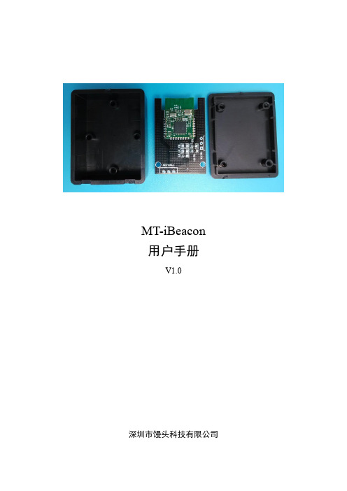
MT-iBeacon用户手册V1.0深圳市馒头科技有限公司版本更新记录目录第1章参数设置 (4)第2章测距功能 (16)第1章参数设置1. 从App Store中下载LightBlue应用到iPhone手机上,安装并打开,点击左下角Central,使手机蓝牙工作在主机模式,开始搜索附近的iBeacon设备(从机设备),即可搜索到由深圳市馒头科技倾力推出的室内定位利器——MT-iBeacon。
2. 点击MT-iBeacon图标连接上设备进行相应的设置。
可以在服务发现里面看到,设备信息,电量信息以及服务UUID。
3. 设备信息展示,此服务用于查看设备的相关信息。
4. 查询设备电量。
此服务用于查询设备的剩余电量,如图所示为剩余100%的电量。
5. 服务UUID。
进入服务UUID,可以看到总共有7个服务,这7个服务的功能见下表1-1 服务功能表。
表1-1 服务功能表图1-1 设置UUID图1-2 设置major图1-3 设置minor图1-4 设置MeasuredPower图1-5 设置发射功率图1-6 设置广播间隔图1-7 设置LED状态第2章测距功能1. 从App Store中下载Locate iB应用到iPhone手机上,安装并打开,可以看到界面如下图。
2. 点击Locate iBeacons按钮,进入下一级菜单,搜索当前可连接的iBeacon设备。
3. 测距校准。
1) 点击Visible iBeacon进入下级菜单,屏幕上有显示Major、Minor、RSSI、Accuracy等信息,下面有两个按钮,Distance——测距,Calibrate——校准。
点击Calibrate进行校准。
2) 根据提示,需要将手机放在离iBeacon 1米处的位置,然后点击,并且保持30s~60s的时间,才能完成校准。
3) 校准中。
4) 校准完成!4. 测距。
校准完成后,回到上一级菜单,点击Distance开始测距。
大学毕业设计---基于cc2540的蓝牙40模块与pc机通信设计

摘要CC2540模块是TI(Texas Instruments)公司开发的一款用于蓝牙4.0开发的系统单晶片解决方案。
利用它可以作为无线数据采集和收发的无线终端,蓝牙4.0技术构建的无线数据采集传输模块,具有功耗低,可靠性高和高安全性的优点,可以用作无线数据传输系统的数据采集端。
因此,研究蓝牙4.0技术构建的与PC机进行无线数据传输通信的系统具有重大的现实意义和应用前景。
设计的主要内容:设计并制作基于CC2540模块的数据采集终端。
系统主要完成利用蓝牙4.0协议栈的编写,实现数据采集终端与PC之间的无线数据通信。
数据采集端由TI官方的CC2040EM核心板和外围电路,如按键、LCD、DS18B20组成,PC端由TI官方的CC25640 USBDongle和串口调试软件组成。
本设计主要论述了蓝牙4.0协议栈的编写及应用,CC2540模块与PC的数据传输过程及原理。
其中,对蓝牙4.0协议栈的编写及应用进行重点论述。
从机端(数据采集模块)的工作主要是对硬件电路的设计和蓝牙4.0协议栈SimpleBLEPeriphral工程的编写;主机端(PC和USBDongle)的工作主要是对USBDongle中HostTestRelease工程的编写和BTool软件的调试。
最终实现数据采集模块采集到的数据能通过蓝牙4.0协议无线传输到PC端,并且PC端能控制数据采集端或向其发送数据。
AbstractCC2540 module is a system used for the development of Bluetooth 4.0 single chip solutions provided by TI (Texas Instruments) company to develop. Because the Bluetooth 4.0 technology has the advantages of low power consumption, high reliability and long distance, it can be used as the wireless terminals of wireless data acquisition.The main elements of design :Designing and fabricating the wireless data acquisition terminal based on CC2540 module, implementing the wireless communication between the wireless data acquisition terminal and PC. The data acquisition terminal is composed of the TI official CC2540EM and peripheral circuit, such as key, LCD, DS18B20. PC comprised TI official CC2540 USBDongle and the serial debugging software.This paper made a briefly introduction of the overview, prospects of application and the basic structure of the data acquisition and transmission of Bluetooth technology. The main elements of the article discusses the compiling and application of the Bluetooth 4.0 protocol stack and the procedure and principle of data transmission between CC2540 module and PC.目录摘要 (I)Abstract ............................................................................................................................... I I 目录 (III)引言 (1)1绪论 (2)1.1蓝牙应用现状 (2)1.2研究目的和意义 (3)2开发环境 (4)2.1硬件环境 (4)2.1.1蓝牙芯片CC2540 (4)2.1.2CC2540EM核心板。
蓝牙4.0 BLE 协议栈的研究 TI CC2540 CC2541 OSAL

1.蓝牙:a 是一种支持短距离通讯的无线技术,主要工作在2.4GHz频带。
至今分为五个版本1.1,1.2,2.0,3.0,4.0(4.1),现在市面上流行三种设备传统蓝牙(Bluetooth简称BR),低功耗蓝牙(bluetoothSmart即是Bluetooth Low Energy简称BLE,蓝牙4.0(BluetoothSmartReady 即是BR+BLE))b 蓝牙4.0由传统蓝牙,高速蓝牙和蓝牙低功耗三种规范合成。
其中常用的有两种模式(单模->支持(BLE)和双模->支持(BLE+BR))。
我们用的CC2540是单模芯片。
c 蓝牙4.0中的BLE(蓝牙低功耗Bluetooth Low Energy)定义了两个频段2.4Ghz(16个信道896/915MHz(896M一个信道915M十个信道),共27个信道。
速度:支持1Mbps数据传输率下的超短数据包。
所有连接都使用蓝牙2.1加入的减速呼吸模式(sniff subrating)来达到超低工作循环跳频:蓝牙规范自适应跳频技术主控制:更加智能,可以休眠更长时间,只在需要执行动作的时候才唤醒。
延迟:可在3ms内实现连接并设置数据传输。
范围:提高调制指数,最大范围可到100m健壮性:所有数据包都经过24bitCRC校验。
确保最大程度抵御干扰。
安全:使用AES128 CCM加密算法进行数据包加密和认证。
拓扑:每个数据包的每次接收都是用32位寻址,理论上可连接十亿台设备。
针对一对一连接,并支持新型拓扑的一对多连接。
d 蓝牙4.0总共40个信道,都分布在2.4GHz,其中0.12.39三个信道用来广播信息。
e 蓝牙4.0的引起超低的功耗而备受瞩目。
是3.0的升级版,较3.0更加省电,成本更低,3ms低延迟,超长有效连接距离,AES-128加密;2.BLEa.蓝牙4.0规范中的一种,其中master最多有7个外设,低功耗,低延迟,低吞吐量。
- 1、下载文档前请自行甄别文档内容的完整性,平台不提供额外的编辑、内容补充、找答案等附加服务。
- 2、"仅部分预览"的文档,不可在线预览部分如存在完整性等问题,可反馈申请退款(可完整预览的文档不适用该条件!)。
- 3、如文档侵犯您的权益,请联系客服反馈,我们会尽快为您处理(人工客服工作时间:9:00-18:30)。
CC2540:超节能蓝牙芯片方案
Bluetooth Low Energy 是蓝牙标准组织Bluetooth SIG 为应对来自其他低功耗无线标准竞争,新开发的超低功耗蓝牙传输标准。
德州仪器的CC2540 是一
款高性价比、低功耗的片上系统(Soc)解决方案,适合蓝牙低耗能应用,它
以低总体物料清单成本,建立强健的网络节点成为可能。
CC2540 基本特性
CC2540 包含一个出色的工业标准的8051 内核的RF 收发器,系统编程闪存记忆,8kB RAM 和其他功能强大的配套特征以及外设。
CC2540 适用于低功耗系统,超低的睡眠模式,以及运行模式的超低功耗的转换进一步实现了超低功耗。
CC2540 有2 中不同的版本:CC2540F128/F256,分别拥有128kB 和256kB 闪存记忆。
与TI 的蓝牙低功耗协议栈相连接,CC2540F128/256 形成市场上既灵活又高性价比的单模式蓝牙低耗能解决方案。
图1 CC2540 原理图CC2540 蓝牙低能耗片上系统主要特性•单芯片器件,6mm×6mm封装中的集成型控制器、主机与应用可缩小物理尺寸,降低成本•基于闪存,器件固件可进行现场更新,数据
可片上存储,从而可为开发商提高灵活性•TI 完整的解决方案,低功耗RF IC、全面的嵌入式单模式协议栈、配置文件软件以及应用支持•RF 性能,出色的长距离链路预算(高达+97dB)以及与其他2.4 GHz 器件的良好共存性•互操作性/兼容性:符合蓝牙规范4.0 版标准的单模式(CC2540)与双模式器件(BlueLink 7.0 蓝牙/FM 单芯片解决方案、WiLink 7.0 WLAN/GPS/蓝牙/FM 单芯片解决方案以及WiLink 6.0 WLAN/蓝牙/FM 单芯片解决方案)可实现全面的链路测试与开发CC2540 方案特点CC2540 开发套件提供了完整的硬件性能测
试平台和通用的软件开发环境的单模蓝牙低功耗(BLE)应用程序。
该套件包
括两个基于CC2540 RF 评估模块、一个基于CC2540-USB 加密狗、软件和硬件原型、电缆、天线和文档,运行快速,轻松地与CC2540 的通用开发板。
