康巴丝7942语音数码信息历使用说明书
康巴丝compas说明书

康巴丝compas电子闹钟说明书产品参数:•品牌:康巴丝(Compas)•商品名称:康巴丝电子闹钟•商品毛重:185.00g•材质:塑料•机芯:电子产品功能:1、正常时间功能:显示时间、日期(从2000年至2099年)、星期、温度,并可实现12/24小时制的转换。
2、闹钟和贪睡功能:闹钟音乐有8首可选,同时可开启贪睡功能。
3、环境温度显示功能:环境温度显示0-500℃或320-1220℉并可进行摄氏/华氏温度转换。
4、七彩灯功能:可发出七种颜色的光,循环变色。
操作方法:1、时间日期设置:★按 SET 键进入时间、日期的设置,并以下列顺序分别设置小时分钟、年、月、日、星期等,通过 UP / DOWN 键配合来完成设置。
★设置范围:时为1-12或0-23,分为0-59,年为2000-2099,月为1-12,日为1-31;在日期设置的同时,星期相应的自动改变。
★在设置状态,也可按 AL 键或无按键1分钟退出设置,并显示当前所设置的时间。
★在正常状态,按 UP 键进行12和24小时转换。
2、闹钟和贪睡设置:★在正常状态,按 AL 键一次进入闹钟模式。
★在闹钟状态,按 SET 键进入闹铃设定状态,以下列顺序分别设置小时、分钟、贪睡、音乐,通过 UP /0OWN键配合来完成其设置。
★在设置状态,如果无按键1分钟或按 MODE 键退出设置,并显示当前所设置的时间。
★在闹钟状态,通过 UP 键开启闹铃的标志,按第二次 UP 键开启贪睡功能。
★当闹钟到达设定时间,响闹1分钟;当贪睡时间到,按 SET 键取消响闹或按任意键停止响闹。
★贪睡的间隔延续时间范围设定:1-60分钟。
★当闹铃及贪睡的标志未开启时,即闹铃和贪睡同时关闭,只有在闹钟标志开启时,重按 UP 键,贪睡功能才有效。
3、温度转换在正常状态,技 DOWN 键可以进行摄氏1华氏温度间的相互转换。
4、按 TAP 可开启夜灯,5秒钟自动熄灭。
5、把开关置 ON 或 DEMO 位置开启七彩灯。
康巴丝7942语音数码信息历使用说明书
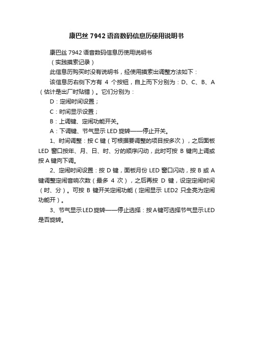
康巴丝7942语音数码信息历使用说明书
康巴丝7942语音数码信息历使用说明书
(实践摸索记录)
此信息历购买时没有说明书,经使用摸索出调整方法如下:
该信息历右侧下方有4个按钮,自上而下分别为:D、C、B、A (估计是出厂时贴错)。
它们分别为:
D:定闹时间设置;
C:时间显示设置;
B:上调键、定闹功能开关。
A:下调键、节气显示LED旋转——停止开关。
1、时间调整:按C键(可根据要调整的项目按多次),之后面板LED窗口按年、月、日、时、分的顺序闪动,此时可按B键向上调或按A键向下调。
2、定闹时间设置:按D键,面板月份LED窗口闪动,按B或A 键调整定闹音响次数(最多4次),之后再按D键,设定定闹时间(时、分)。
可按B键开关定闹功能(定闹显示LED2只全亮为定闹功能开)。
3、节气显示LED旋转——停止选择:按A键可选择节气显示LED 是否旋转。
卡西奥 QT-2100智能终端用户手册说明书
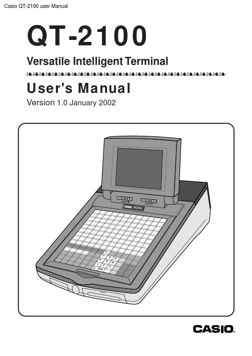
Casio QT-2100 user ManualQT-2100Versatile Intelligent TerminallllllllllllllllllllllllllllllllUser's ManualVersion 1.0 January 20023QT-2100 User's Manual GUIDELINES LAID DOWN BY FCC RULES FOR USE OF THE UNIT IN THE U.S.A.(Not applicable to other areas)WARNING: This equipment has been tested and found to comply with the limits for a Class A digital device, pursuant to Part 15 of the FCC Rules. These limits are designed to provide reasonable protec-tion against harmful interference when the equipment is operated in a commercial environment. This equipment generates, uses, and can radiate radio frequency energy and, if not installed and used in accordance with the instruction manual, may cause harmful interference to radio communications.Operation of this equipment in a residential area is likely to cause harmful interference in which case the user will be required to correct the interference at his own expense.FCC WARNING: Changes or modifications not expressly approved by the party responsible for compliance could void the user’s authority to operate the equipment.The main plug on this equipment must be used to disconnect main power.Please ensure that the socket outlet is installed near the equipment and shall be easily accessible.Zur Trennung vom Netz ist der Netzstecker aus der Steckdose zu zielen, welche sich in der Nähe des Gerätes befinden muß und leicht zuganglich sein soll.Please keep all information for future reference.Contents1.Equipment care (2)2.QT -2100 overview (4)3.How to remove/replace the sheet holder (5)4.How to install a menu sheet in the sheet holder (6)5.Tilt the LCD panel (8)6.Troubleshooting (9)7.List of options (10)8.Specifications (11)This is a “Table of Contents preview” for quality assuranceThe full manual can be found at /estore/catalog/ We also offer free downloads, a free keyboard layout designer, cable diagrams, free help andsupport. : the biggest supplier of cash register and scale manuals on the net。
手表使用说明
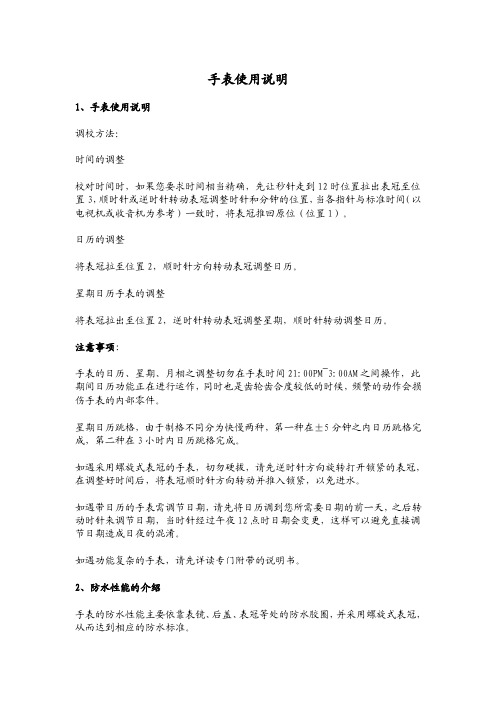
手表使用说明1、手表使用说明调校方法:时间的调整校对时间时,如果您要求时间相当精确,先让秒针走到12时位臵拉出表冠至位臵3,顺时针或逆时针转动表冠调整时针和分钟的位臵,当各指针与标准时间(以电视机或收音机为参考)一致时,将表冠推回原位(位臵1)。
日历的调整将表冠拉至位臵2,顺时针方向转动表冠调整日历。
星期日历手表的调整将表冠拉出至位臵2,逆时针转动表冠调整星期,顺时针转动调整日历。
注意事项:手表的日历、星期、月相之调整切勿在手表时间21:00PM~3:00AM之间操作,此期间日历功能正在进行运作,同时也是齿轮齿合度较低的时候,频繁的动作会损伤手表的内部零件。
星期日历跳格,由于制格不同分为快慢两种,第一种在±5分钟之内日历跳格完成,第二种在3小时内日历跳格完成。
如遇采用螺旋式表冠的手表,切勿硬拔,请先逆时针方向旋转打开锁紧的表冠,在调整好时间后,将表冠顺时针方向转动并推入锁紧,以免进水。
如遇带日历的手表需调节日期,请先将日历调到您所需要日期的前一天,之后转动时针来调节日期,当时针经过午夜12点时日期会变更,这样可以避免直接调节日期造成日夜的混淆。
如遇功能复杂的手表,请先详读专门附带的说明书。
2、防水性能的介绍手表的防水性能主要依靠表镜、后盖、表冠等处的防水胶圈,并采用螺旋式表冠,从而达到相应的防水标准。
手表的防水性能通常按其等级分为:不防水(表后盖勿标识)。
防汗(SWEAT-RESISTANT)。
一般性防水(WATER-RESISTANT),30米防水(30M、3ATM、3BAR),50米防水(50M、5ATM、5BAR)。
潜水表100米防水,200米防水,300米防水等。
关于手表的防水性能,国家标准和国际标准都有明确的规定:凡是标明防水的手表,最低要耐受2个大气压,即20米水深处不进水。
30米防水表示手表可以耐受3个大气压,依此类推。
此标准的前提是在进行测试的时候是在实验室条件下:温度保持在20-25摄氏度,且手表和水都呈静止状态。
康巴丝电子充电时钟说明书

康巴丝电子充电时钟说明书
在调整康巴丝电波钟表的时候,先将钟表翻过来,在上面找到一个装电池的地方,将其打开后装入新的5号电池。
再将后面的圆珠部分拔出来,待指针全部指向12的位置上等几分钟,让其根据电波信号自动校正时间即可。
康巴丝电波钟表调时间的方法
在调节康巴丝电波钟表时间的时候,先将钟表倒过来,在上面找到一个黑色的装置部分,里面的小型方块的就是放电池的地方,这时候可将新的5号电池放进去,但要注意正负极不要放反,以免出现短路现象。
将电池塞进去后,钟表还是不会走动的,这时候要在后面找到一个白色的圆珠,而这也是防止指针乱走动的装置,手指拿着圆珠后拔出来,这时候钟表就会开始走动,将分针和时针、秒针都走到12的位置上。
此时钟表就会自动的接受电波信号,而在这个时候要等几分钟,之后就会看到钟表的指针自动校正,将时间对准后,再将圆珠的部分插进去,将电池的后盖装进去,这样就调整好时间了。
数码手表使用说明书

数码手表使用说明书(录音、摄像、拍照手表)一、界面功能定义:图片仅供参考,请以实物为准二、指示灯状态说明:1、手表时钟的2点位置为绿灯指示;4点位置为红灯指示。
2、绿灯长亮:表示录像待机状态;红灯长亮:表示录音待机状态;红绿灯二灯同时长亮:表示拍照待机状态。
3、绿灯慢闪烁3下后熄灭:表示录像工作状态;红灯慢闪烁3下熄灭:表示录音工作状态;红绿灯同时慢闪烁一下:表示拍照一张照片。
4、开机后红绿灯二灯同时慢闪烁三下后关机:表示没有检测到内存卡。
5、录像;录音;拍照待机状态下准备工作开始时,快闪一下后回来待机状态:表示内存空间不足。
6、开机后待机状态下红灯快闪烁三下后关机:表示电量不足。
7、数据线充电或连机时红灯长亮:表示正在充电状态;如果红灯灭绿灯长亮:表示电池已充满状态。
8、连接数据线红灯快速闪烁:表示设备正在读取或者传输文件,请误中断数据连接,以免损坏文件。
三、操作步骤使用说明:第一步安装记忆卡: (TF卡)按指示旋转打开手表底盖,正确拆卸本机电池后打开记忆卡槽盖,将通用的TF卡安装在卡槽内盖好,然后将卸下的电池正确安装好旋紧手表底盖即可使用。
第二步开机:首先按2点位置和4点位置的螺母按键旋到底部,(注意:不使用按键时请将这二个按键螺母旋出顶部,可防止按键误操作且能延长按键的使用寿命),长按2点位按键二秒以上,指示灯亮起即可松开按键,绿灯长亮时表示录像准备状态。
第三步切换功能准备状态:在绿灯准备状态时短按一下4点位置按键,切换到红灯长亮表示录音准备状态;再短按一下4点位置按键切换到红绿灯长亮表示拍照状态,三者间循环切换。
第四步各功能工作状态:在录像准备状态短按一下2点位按键,此时绿灯慢闪烁三下后熄灭表示正在录像;同样在录音准备状态短按一下2点位按键后,此时红灯慢闪烁三下后熄灭表示正在录音,同样拍照准备状态短按一下2点位按键后,此时红绿灯同时慢闪烁一下:表示拍照一张照片,连续按开机键,可以连续拍几张照片。
哈密顿自动计时码表面对面II有限版产品说明书

FACE 2 FACE II | LIMITED EDITION | 说明书自动计时码表请参考通用用户手册中的时间设置和使用说明。
启动 / 停止重启2© HAMILTON - JuNe 2016按压以转动表壳M045 - INSTRuCTION MANuAL 3将表壳锁定在中心位置4© HAMILTON - JuNe 2016欲了解更多信息,请访问/customer-service/user-manuals重启启动 / 停止M045 - INSTRuCTION MANuAL 56 © HAMILTON - JuNe 2016123脉搏计 (最低心率示数:30下/分钟)计时码表配有心率刻度。
步骤按住脉搏。
启动计时功能,数到第30下脉搏,然后停止计时功能。
可立即从脉搏计刻度上读取结果。
示例:每分钟75下重启计时功能。
M045 - INSTRuCTION MANuAL 7123速度计计时码表配有平均速度刻度,总量程为1公里或1英里,单位是公里/小时或英里/小时。
仅适用于不超过60秒钟的测量时长。
步骤在1公里或1英里开始时启动计时功能,然后在这一路程结束时停止计时功能。
此时秒针所指向的速度计上的刻度示数便是以公里/小时或英里/小时为单位的平均速度。
示例:120公里/小时或120英里/小时重启计时功能。
8 © HAMILTON - JuNe 2016123测距仪计时码表配有可以测量距离的刻度,方法是测量某种现象开始到该种现象所造成的声音信号之间的时间间隔。
例如可以通过测量闪电和雷声之间的时间差,测量出雷雨距离我们有多远。
步骤当观察到闪电时启动计时功能,然后当听到雷声时停止计时功能。
可立即从刻度上读取结果。
示例:13公里重启计时功能。
860000045M 045。
日历钟使用说明教案设计

日历钟使用说明教案设计一、教学目的1.能够正确使用日历钟,并掌握其基本功能。
2.了解日历钟的特点,以及其相关知识点。
二、教学内容1.日历钟的定义及其分类2.日历钟的部件及其特点3.日历钟的使用方法三、教学重点1.掌握日历钟的基本使用方法。
2.了解日历钟的功能,以及日历钟的特点。
三、教学难点1.准确识别日历钟的各部件,了解功能。
2.通过讲解和实操掌握日历钟的各项功能。
四、教学方法1.讲授法:通过教师讲解、幻灯片课件等方式向学生传授日历钟的相关知识。
2.实操法:通过教师示范和学生实操的方式,加深学生对日历钟的认识和掌握。
五、教学过程设计1.教学前的准备工作(1)检查教学用具是否完备。
(2)了解学生的学习情况,尤其是他们对日历钟的了解情况。
2.教学过程(1)引入:通过展示日历钟的样品,引起学生的兴趣。
(2)认识日历钟的部件:通过对日历钟各部件的介绍,使学生准确识别各部件,了解其功能。
(3)了解日历钟的分类:通过讲解不同类型的日历钟,让学生了解其根据使用范围的不同,出现了不同类型的日历钟。
(4)讲解日历钟的功能:通过介绍日历钟的显示功能,告诉学生如何读取时间、日期等信息,以及如何调整日历钟时差、闹钟等功能。
(5)实操日历钟:老师进行示范,然后让学生自己实操日历钟,并进行检查。
(6)让学生进行小组讨论,就日历钟的使用方法和功能等方面进行探讨。
3.教学过程的总结(1)总结本次教学的主要内容和要点。
(2)回答学生提出的问题。
六、教学评估通过教学后的测试,检查学生对日历钟的掌握情况,以及对相关知识点的了解程度等。
根据测试结果,及时调整教学方法和教学内容。
马达万年历手表

马达万年历手表功能介绍:1.时钟 + 日期+星期+ 秒表(使用4个可360°转动的2°/步或1°/步正马达) 。
2.工作电压3.0V.3.4键(A、B、C、D)操作。
4.码表范围:59分59秒,超出范围会自动停止。
5.上电复位时间:2020年7月18日,AM1:00,SA.6.年份范围:2020-2024年。
7.上电状态:上电2秒后,开始时钟走时和进行首次自检模式[各马达自转或摆动(60分钟)] 。
按任意键停止自检返回睡眠模式;自检模式完成后,只有M4马达位于数字1号位置;其他马达位于0°,并保持不动,表示完成了自检模式,按任意键才返回时间/日期模式。
8.另配置一单独马达功能:M5(可360° 转动的2°/步或1°/步正马达)代表另1个时钟(分带时),由另一单独D键控制,每20S正转一步。
开机进行自检模式,1小时自动停止后M5(分带时)返回至起始位,在自检模式时,可按任意键停止自检返回睡眠模式。
在睡眠模式,M5停止不动。
9.3等级LED灯效果(3秒高亮度、8小时低亮度、24小时低亮度)。
时间/日期模式:1、M1代表星期、年/月/日期/时/分指示,M2代表年/日期/小时/分钟十位,M3代表年/日期/小时/分钟个位,M4代表月份;在时间/日期模式;M5代表另一时钟,每20秒更新马达位置。
2、时间/日期模式下,短按A键1次可切换至秒表模式,进入秒表模式时, M2/M3自动清零(马达位置为0°), M1/ M4保持星期和月显示,M5保持时钟走时。
3、时间/日期模式下,短按B键1次可切换至DEMO模式。
DEMO模式下,4个(M1/M2/M3/M4)马达自转1圈约12S, DEMO模式下按键没效;自转12S后返回时间模式,M5保持更新马达位置。
4、时间/日期模式下,短按B键3次可切换至睡眠模式,M1/M2/M3/M4马达归零(马达位置为0°),M5停止走时。
电子钟(万年历)说明书

河北工程大学科信学院课程设计说明书(2012 /2013 学年第 1 学期)课程名称:小型数字系统设计1题目:电子钟专业班级:计算机1021班****:***学号:*********指导教师:赵建明蔡恒设计周数: 1 周设计成绩:二〇一三年一月十八日一、选题意义电子钟是对时、分、秒等用数字显示的计时装置,广泛用于个人家庭、车站、办公室等公共场所,成为人们日常生活中不可少的必需品。
钟表的数字化给人们生产生活带来了极大的方便,而且大大地扩展了钟表原先的报时功能。
诸如定时自动报警、按时自动打铃、时间程序自动控制、定时广播、自动起闭电路、甚至各种定时电器的自动启用等,所有这些,都是以钟表数字化为基础的。
因此,研究数字电子钟及扩大其应用,有着非常现实的意义。
二、项目设计方案2.1 硬件选取与说明2.1.1硬件选择及数量AT89C51 单片机1个、 7SEG-MPX1-CC (1位七段数码管)1个、7SEG-MPX2-CC(1位七段数码管)5个、7SEG-MPX4-CC(1位七段数码管)1个、NPN三极管一个、蜂鸣器一个、七段显示译码器7448与74141 BCD—十进制译码器/驱动器各两片。
2.1.2 单片机端口设定单片机端口选择:根据选用的AT89C51单片机将P0口的低4位作为时间数据显示的数据输出端口,高4位作为数码管选择端口。
P1端口的低4位作为日期的数据输出端口,高4位作为日期显示数码管的选择端口。
P2.6端口作为蜂鸣器控制端口,INT0、INT1两中断引脚作为更改数据的按键。
2.1.3 方案设计(1) 方案设计框图见图1图1方案设计框图(2)电路原理图图2电路原理图2.2软件设计2.2.1 系统分析电子钟包含时间、日期、星期的显示。
其中时间包含有秒与分、分与小时之间的逻辑;日期中包含日于月、月与年、星期计算等逻辑;时间与日期之间也存在逻辑。
具体逻辑如下:(1)其中秒最大计数不能超过60,超过60后应置0重新计数。
硅表说明书
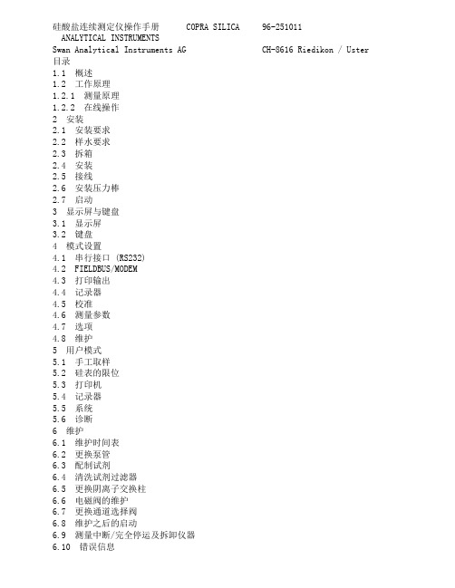
硅酸盐连续测定仪操作手册 COPRA SILICA 96-251011ANALYTICAL INSTRUMENTSSwan Analytical Instruments AG CH-8616 Riedikon / Uster 目录1.1 概述1.2 工作原理1.2.1 测量原理1.2.2 在线操作2 安装2.1 安装要求2.2 样水要求2.3 拆箱2.4 安装2.5 接线2.6 安装压力棒2.7 启动3 显示屏与键盘3.1 显示屏3.2 键盘4 模式设置4.1 串行接口 (RS232)4.2 FIELDBUS/MODEM4.3 打印输出4.4 记录器4.5 校准4.6 测量参数4.7 选项4.8 维护5 用户模式5.1 手工取样5.2 硅表的限位5.3 打印机5.4 记录器5.5 系统5.6 诊断6 维护6.1 维护时间表6.2 更换泵管6.3 配制试剂6.4 清洗试剂过滤器6.5 更换阴离子交换柱6.6 电磁阀的维护6.7 更换通道选择阀6.8 维护之后的启动6.9 测量中断/完全停运及拆卸仪器6.10 错误信息警告仪表符合DIN57411 part 1/VDE 041 part 1、“电子测量仪保护措施”,并且在无故障条件下出厂。
为了保持这种无故障状态和保证无操作错误,用户必须重视所有的警告并且严格按照《操作手册》操作。
严禁不接地。
外部或内部保护地线的断裂或松弛可能会导致危险。
当需要进行电气检修时必需在未通电状态下。
打开仪表或移动其部件时须小心,连接应紧固。
检修须由指定人员进行。
若仪表不能正常运行,就必须切断所有电源,并停止操作。
如有下述情况发生,不能进行安全操作:- 在运输或安装过程中明显损坏。
- 仪表不工作。
- 在不良环境下储存期过长仪表附件的任何连接都必须按照IEC 950/EN 60950,UL1950或UL478标准。
注意:没有试剂仪表不能工作。
试剂可以在Swan公司各地的经销商处购买。
Omega 设备产品说明 - 时间记录器说明书

Weight: 24 g (0.9 oz)
Materials: Data Logger: ABS Plastic Waterbox Enclosure: Black anodized aluminum
Software: XP SP3/Vista/Windows 7 (32 and 64-bit)
Operating Environment: -40 to 80ºC (-40 to 176ºF), 0 to 95% RH non-condensing
Dimensions: Data Logger: 36 H x 56 W x 16 mm D (1.4 x 2.2 x 0.6")
OM-CP-IFC200, Windows® software displays data in graphical or tabular format
To Order visit /om-cp-state101a for Pricing and Details
Model No.
Description
for 5 seconds, the green LED will
flash during this time. The device
has started logging.
Specifications
Input Connection: Removable screw terminal
To Stop the Device:
1
OM-CP-STATE101A
Average battery life vs. reading rate the OM-CP-STATE101A
Omega CT7300系列双圆环图表记录器用户指南说明书

e-mail:**************User’s GuideCT7300 SERIES2 Pen Circle Chart RecorderShop online at®1apply. OMEGA is constantly pursuing certification of its products to the European New Approach Directives. OMEGA will add the CE mark to every appropriate device upon certification.The information contained in this document is believed to be correct, but OMEGA Engineering, Inc. acceptsno liability for any errors it contains, and reserves the right to alter specifications without notice.WARNING: These products are not designed for use in, and should not be used for, human applications.i11-2 CT7300 Ordering CodeModel CT7310Dual Pen RecorderModel CT7311Dual Pen Recorder W/Alarm RelayPen1Model CT7312Dual Pen Recorder W/Alarm RelayPen1&2All Recorders are provided with mounting brackets,batteryAnd1box of chartsSpare PartsReplacementRed Pens P/N7300-Red(6/package) ReplacementGreen Pens P/N7300-Green(6/package)Charts standard P/N CT7000C-100-24(0/100,24hr)100charts/box234Install both mounting clamps and insert the case into panel cutout.Upon unpacking,find a suitable location to mount the recorder before wiring power to the unit.After the recorder has beenconnected to the main AC power supply,install the 9VDC battery in it's holder.Select a location that is well lighted,free from dust,dirt or corrosive fumes.The instrument should not be located near any sources of heat or be subject ot sudden or extreme temperaturechanges.It should be mounted on a rigid support that is not subject otvibration.Refer to figure 6.1for recorder case dimensions.2-3 Case LocationThe Panel cut out is 32.3 x 32.3 cm (12.72 x 12.72 in.)5Unused control terminals should not be used as jumper points as they may be internallyconnected,causing damage to the unit.Verify that the ratings of the output devices and the inputs as specified in Chapter 5are not exceeded.Electric power in industrial environmentscontains a certain amount of noise in the form of transient voltage and spikes.This electrical noise can enter and adverselyaffect the operation ofmicroprocessor-based controls.For this reason we stronglyrecommend the use of shielded thermocouple extensionwire which connects the sensor to the unit.This wire is a twisted-pairconstruction with foil wrap and drain wire.The drain wire is to be attached to earth ground at the sensor end only.2-4 Wiring PrecautionsBefore wiring,verify the label for correct model number and options.Switch off the power when checking.•••••••••Care must be taken to ensure that maximum voltage ratingspecified on the label are not exceeded.It is recommended that power of these units to be protected by fuses or circuit breakers rated at the minimum value possible.All units should be installed inside a suitably grounded metal enclosure to prevent live parts being accessible from humanhands and metalAll wiring must conform to appropriate standards of good practice and local codes and regulations.Wiring must be suitable formaximum voltage,current,and temperature rating of the system.T ake care not to over-tighten the terminal screws.67P E N 1P E N 212341234RelayOptionalRelayOptional J 3J 4J 2J 12-12 Marking SystemsThis type of pen consists of a self contained ink reservoir with a porous plastic stylus which is snapped around the outer edge of the metal pen arm.A pen cap is provided to extend the life of the ink pen during shipping or when the recorder is not in service.T o remove the pen cap,gently lift the pen arm away from the chart paper.Remove the black plastic pen cap to expose the fiber tip of the ink pen and gently place the pen back onto the chart paper.Do not let the pen arm "snap"back onto the chart paper.This will flatten the fiber tip of the pen and will no longer give you a fine line marking on the chart paper.Place the pen cap in a safe place for future use.If the stylus does not touch the chart,adjustment can be made by slightly bending the metal pen arm in the center towards the chart paper.Do not use more pressure than is necessary to create a fine line marking on the chart paper.Note:As the pen ink supply runs out,the pen color will become lighter .This indicates that the pen should be replaced.2-11 Changing the ChartPress and release the CHANGECHART key (3on Figure 3.1).The pen(s)will move to the left of the chart and green LED will flash rapidly .Wait until the pen(s)stops above outer ring green LED goes to on steady .Unscrew the chart "hub"knob at the center of the chart.Removethe old chart paper and position the new one so that the correct time line coincides with the time line groove on the chart plate.Refer to Figure 2.4for the location of the time line groove.Re-attach the chart "hub"knob and screw securely (by hand)against the chart.Press and releasethe CHANGECHART key (3).The pen will move to the outer ring,green LED remains on,then pauses.If alarms are enabled pen(s)will then move to current alarm setpoints.For information to set these setpoints please see Chapter 3.If alarms are not enabled after pausing at outer ring,pens will go to current recording value.Check to make sure that the pen(s)are marking on the chart paper.If it is not,then carefully adjust the pen arm to establish contact with the paper.AND2-13 Replacement of PenRecorders that are equipped with fiber tipped cartridge pens are colored coded RED for pen1and GREEN for pen2.The pen cartridge is securely fastened to the metal pen arm using a special "U"clip tab.For ease of replacement,it is suggested that the two(2)screws that hold the pen arm be loosened and the pen cartridge and metal pen arm be removed as an assembly.Refer to Figure2.5for the location of the pen arm screws. Unsnap the plastic"U"clip tab of the pen cartridge from the metal pen arm, remove and discard the old pen cartridge.Replace the new cartridge by opening the hinge and snapping it securely around the metal pen arm.Refer to Figure2.4for pen cartridge replacement.Figure2.4Pen ReplacementIn order to configure the recorder ,you will need the recorder SET-UP CHART.These charts contain the configuration categories of the recorder (Probe Input,Inner Chart V alues,Outer Chart V alues,Units,Chart Rotation,Input Averaging and RelayOptions).Place the SET-UP CHART onto the recorder.This setup chart could be left on the recorder behind the normal recording chart for easy access or behind the platen assembly .1.Place SETUPCHART on recorder .2.Press and releaseCHANGECHART key (3),pens will begin to move off scale and green LED will flash rapidly .Wait until pens are off scale Green LED goes to on steady .3.Press and hold LEF T arrow key (1)until green LED turns off.Thenreleasekey .Pens will move to outer ring.Wait for green LED to flashslowly .(.8sec on/.8sec off)Note;Green LED will continue to flash slowly during setup mode.4.Green Pen will move to outer ring of SETUPCHART first.Then Red pen will then move to outer ring.Pleasenote green pen setup selectionsallowed are only for categories and selections.5.Loosen chart knob and rotate chart to position pen in middle of the ST ARTCIRCLE .6.Tighten chart knob.Press and release the CHANGECHART key (3).Red Pen will move to first selection category to current value.Position red pen to desired selection using LEF T (1)and RIGHT (2)keys.7.Press and releasethe CHANGECHART key (3)to store selection.Green Pen will now advance to current selection.Position Green pen to desired selection using LEF T (1)and RIGHT(2)arrow keys.Press and release CHANGECHART key (3)to store selection.Green pen will now move to outer ring.Green pen will remain at outer ring until Relay category .8.Repeat selection process in EACH category until all categories areselected.Green pen shares program information selected by Red pen.9.After last category (Relay)is selected,press and release CHANGE CHART key (3).Pens will move off scale.Green LED will flash rapidly .Wait until Green LED goes to on steady .Setup is now complete.10.Remove/store SETUPCHART.Install actual recording chart to be used.11.Press and release CHANGECHART(3)key .Pens will move to 100%ring,then to relay setpoints ,if programmed.Then to actual recording values AND Input Probe Relay Red .Chapter 3 Programming3-1 Recorder SetupFigure 3.1Keypad LayoutAlarm setpoint values are selected by positioning the pen to the actual value on the recording chart.Alarm settings can be selected or viewed after CHARTCHANGE,recorder setup or during initial power up.T o set the alarm setpoint during normal recording operation,complete the following steps.Press and releasethe CHANGECHART key (3on Figure 3.1).(3on Figure 3.1)Wait until pen(s)moves off scale and LED status changes from flashing to steady .Press and releasethe CHANGECHART again,the pen will begin to move back onto the chart briefly stopping at (or close to)the outer most graduation of the chart.Green LED remains on steady during this time.Sin le Alarm SettingAfter the above operation is complete,the pen(s)arm will move to thecurrent alarm setpoint position on the chart (one pen at a time).The green LED will go out,during this time the alarm setpoint (for each pen)can be adjusted using the LEF T arrow (1)or the RIGHTarrow (2)keys on the keypad.Once the alarm setpoint is set,wait for the green LED will turn on and the pen arm will move to indicate the probe's temperature and the unit will begin normal recording operation.Band Alarm SettingThe "Change Chart"key is the "RESET"when the recorder is programmed for latching alarm operation.Please note relay will only reset if alarmcondition has been cleared.When programming the recorder for operation,the pen(s)will move to the first band setpoint on the chart.The green LED will go out.The alarm band 1setpoint can now be adjusted using the LEFT arrow (1)or the RIGHTarrow (2)keys,once set,wait for the green LED to turn on.Theactive pen will then move to the second band alarm setpoint.The green LED will go out.The alarm band 2can now be adjusted.When pen(s)alarm setpoints adjustments are completed,wait for the green LED to turn on and the pen arm will move to indicate the probe's temperature and the unit will begin normal recording operation.band alarm g 3-2 Alarm SettingsPen calibration is a two point calibration.T o check and/or adjust therecording pen(s)calibration to the inner and outer graduations of the chart,Perform the following.1.Removepower to instrument.If unit has battery option also remove battery .2.With all power removed,press and hold the CHANGECHART key (3).Whileholding the CHANGECHART key(3),re-apply power .Release key upon applying power ,either AC or battery which ever is convenient.3.The pens will move off scale,LED will flash rapidly .Green LED will then go to steady on.4.The green pen will then move to 100%ring.Adjust green pen using LEF T (1)and RIGHT(2)keys to position pen on 100%ring,thenWait.5.Red pen will then move to 100%ring.Adjust this pen to 100%ring,using LEF T (1)and RIGHT(2)keys,then wait.6.Red pen will then move to 0%ring.Adjust pen using LEF T (1)and RIGHT(2)keys,then wait.Pen will then move full upscale.7.Green pen will move to 0%ring.Adjust pen to 0%,using LEF T(1)and RIGHT(2)keys,then wait.Green pen will now travel full upscale.8.Pen calibration is now complete.If unit has alarms enabled pens will now go to current alarm settings.See Section 3.2.Then to actual recording value.If no alarms are enabled pens will then go directly to actual recording values.Each time the chart paper or fiber tip pen cartridge is changed,you should make sure that each pen stops at the inner and outer most temperature graduation of the chart paper.Otherwise,this pen offset can cause the unit to record an incorrect temperatureon the chart.Chapter 4 Calibration4-1 Pen Arm Calibration (Zero and Span)Figure 4.1KeypadLayout4-2 Probe Offset Adjustment (pen offset) This recorder has been accurately calibrated at the factory.Before making any adjustments,this instrument should be in service for24hours. Thereafter,if any adjustment is required,perform the following procedure.1.Place a Certified T est Thermometer(s)alongside the recorder'ssensorprobe(s)in a monitored controlled condition.2.Once the temperaturehas leveled out,compare the position of thepen(s)on the recorder to the test thermometer'sreading,also compare the Certified T est Thermometerísreading to the second pen of therecorder.3.For two(2)pen recorders,you must first select the pen that you wish tocalibrate.This is done by pressing the LEF T(1)arrow key to select the Red pen or the RIGHT(2)arrow key to select the Green pen.Theappropriate arrow key must be held down for approximatelyfive(5)seconds until the green LED goes out.Once the green LED goes out, releasethe key.The green LED will begin to flash steady.Adjust theselected pen to the desired value.This is done by using the LEF T(1)or RIGHT(2)arrow keys.Once the corrected value is obtained,wait.Green LED will go to on steady,indicating return to normal recording mode. After temperaturecalibration check is complete,the recorder will return to normal recording mode within5seconds of no further key depression.Chapter 5 SpecificationsPowerInputRecordingOptionsEnvironmental and PhysicalLine V oltage:115/230VAC,50/60HzPower Consumption:15VA maximumThermocouple(T/C):Type J,K,T ,R,B,S,RTD:PT 100ohm RTD(385curve)Linear:4-20mA,0-5VDCRange:See T able 5-1Common Mode Rejection:>120dB at 60HzCold Junction Accuracy:±0.2°C@25°C ambientCold Junction Error:±0.2°C@25°C ambientAmbient Error:±0.01%span/°C from 25°C ambientIsolation:Inputs isolated from outputsChart Size:10°Recording Accuracy:±0.5%of span (100division span)Sensor Break:Full scale Pen <10secondsChart Speed:Programmable for 4, 8,12, 24, 48, 72,168hour rotation Input Filtering:Programmableup to 120secondsBatteryBackup: 9VDC Providesup to 48hours of recordingRelay:DPDT ,1.0Amps @120VAC resistiveRelayProgram:Process,Band,Non-latching,LatchingError Protection:De-energizedduring sensor breakHysteresis:Set at 2units,activation is safe sidedOperating T emperature:0to 60°C (32 to 140°F)Storage T emperature:-40to 65°C (-40 to 149°F)Humidity:0-90%RH (non-condensingAgency Approval:UL /CULInstallationCategory:llPollution Degree:2Altitude:2000metersVibration:0.3to 100Hz @0.2gMounting:±20degrees of vertical±10degrees of horizontal Moldings:Fire retardant Noryl w/acrylic windowPanel Rating :Nema 12X std (Nema 4optional)Dimensions: 35.5 H x 35.5 W x 9.6 D cm (14.00 H x 14.00 W x 3.80 D in.)Panel Cutout:Industry Standard 32.3 x 32.3 cm (12.72 x 12.72 in.)Weight:7pounds maximum1819Direct all warranty and repair requests/inquiries to the OMEGA Customer Service Department. BEFORE RETU RNING ANY PRODU CT(S) TO OMEGA, PU RCHASER MU ST OBTAIN AN AU THORIZED RETU RN (AR) NU MBER FROM OMEGA’S CU STOMER SERVICE DEPARTMENT (IN ORDER TO AVOID PROCESSING DELAYS). The assigned AR number should then be marked on the outside of the return package and on any correspondence.The purchaser is responsible for shipping charges, freight, insurance and proper packaging to prevent breakage in transit.FOR WARRANTY RETURNS, please have the following information available BEFORE contacting OMEGA:1.Purchase Order number under whichthe product was PURCHASED,2.Model and serial number of the productunder warranty, and3.Repair instructions and/or specificproblems relative to the product.FOR NON-WARRANTY REPAIRS,consult OMEGA for current repair charges. Have the following information available BEFORE contacting OMEGA:1.Purchase Order number to cover theCOST of the repair,2.Model and serial number of theproduct, and3.Repair instructions and/or specific problemsrelative to the product.OMEGA’s policy is to make running changes, not model changes, whenever an improvement is possible. This affords our customers the latest in technology and engineering.OMEGA is a registered trademark of OMEGA ENGINEERING, INC.© Copyright 2003 OMEGA ENGINEERING, INC. All rights reserved. This document may not be copied, photocopied, reproduced, translated, or reduced to any electronic medium or machine-readable form, in whole or in part, without the prior written consent of OMEGA ENGINEERING, INC.Where Do I Find Everything I Need for Process Measurement and Control?OMEGA…Of Course!Shop online at TEMPERATUREⅪߜThermocouple, RTD & Thermistor Probes, Connectors, Panels & AssembliesⅪߜWire: Thermocouple, RTD & ThermistorⅪߜCalibrators & Ice Point ReferencesⅪߜRecorders, Controllers & Process MonitorsⅪߜInfrared PyrometersPRESSURE, STRAIN AND FORCEⅪߜTransducers & Strain GagesⅪߜLoad Cells & Pressure GagesⅪߜDisplacement TransducersⅪߜInstrumentation & AccessoriesFLOW/LEVELⅪߜRotameters, Gas Mass Flowmeters & Flow ComputersⅪߜAir Velocity IndicatorsⅪߜTurbine/Paddlewheel SystemsⅪߜTotalizers & Batch ControllerspH/CONDUCTIVITYⅪߜpH Electrodes, Testers & AccessoriesⅪߜBenchtop/Laboratory MetersⅪߜControllers, Calibrators, Simulators & PumpsⅪߜIndustrial pH & Conductivity EquipmentDATA ACQUISITIONⅪߜData Acquisition & Engineering SoftwareⅪߜCommunications-Based Acquisition SystemsⅪߜPlug-in Cards for Apple, IBM & CompatiblesⅪߜDatalogging SystemsⅪߜRecorders, Printers & PlottersHEATERSⅪߜHeating CableⅪߜCartridge & Strip HeatersⅪߜImmersion & Band HeatersⅪߜFlexible HeatersⅪߜLaboratory HeatersENVIRONMENTALMONITORING AND CONTROLⅪߜMetering & Control InstrumentationⅪߜRefractometersⅪߜPumps & TubingⅪߜAir, Soil & Water MonitorsⅪߜIndustrial Water & Wastewater TreatmentⅪߜpH, Conductivity & Dissolved Oxygen Instruments M3908/0403。
- 1、下载文档前请自行甄别文档内容的完整性,平台不提供额外的编辑、内容补充、找答案等附加服务。
- 2、"仅部分预览"的文档,不可在线预览部分如存在完整性等问题,可反馈申请退款(可完整预览的文档不适用该条件!)。
- 3、如文档侵犯您的权益,请联系客服反馈,我们会尽快为您处理(人工客服工作时间:9:00-18:30)。
康巴丝7942语音数码信息历使用说明书
(实践摸索记录)
此信息历购买时没有说明书,经使用摸索出调整方法如下:
该信息历右侧下方有4个按钮,自上而下分别为:D、C、B、A(估计是出厂时贴错)。
它们分别为:
D:定闹时间设置;
C:时间显示设置;
B:上调键、定闹功能开关。
A:下调键、节气显示LED旋转——停止开关。
1、时间调整:按C键(可根据要调整的项目按多次),之后面板LED窗口按年、月、日、时、分的顺序闪动,此时可按B键向上调或按A键向下调。
2、定闹时间设置:按D键,面板月份LED窗口闪动,按B或A键调整定闹音响次数(最多4次),之后再按D键,设定定闹时间(时、分)。
可按B键开关定闹功能(定闹显示LED2只全亮为定闹功能开)。
3、节气显示LED旋转——停止选择:按A键可选择节气显示LED是否旋转。
