LS-QL固件安装
麒麟系统安装与激活步骤指导手册说明书

麒麟系统安装与激活步骤指导手册版权所有©杭州海康威视数字技术股份有限公司2019。
保留一切权利。
本手册的任何部分,包括文字、图片、图形等均归属于杭州海康威视数字技术股份有限公司或其子公司(以下简称“本公司”或“海康威视”)。
未经书面许可,任何单位和个人不得以任何方式摘录、复制、翻译、修改本手册的全部或部分。
除非另有约定,本公司不对本手册提供任何明示或默示的声明或保证。
关于本手册本手册描述的产品仅供中国大陆地区销售和使用。
本手册作为指导使用。
手册中所提供照片、图形、图表和插图等,仅用于解释和说明目的,与具体产品可能存在差异,请以实物为准。
因产品版本升级或其他需要,本公司可能对本手册进行更新,如您需要最新版手册,请您登录公司官网查阅()。
海康威视建议您在专业人员的指导下使用本手册。
商标声明为海康威视的注册商标。
本手册涉及的其他商标由其所有人各自拥有。
责任声明●在法律允许的最大范围内,本手册所描述的产品(含其硬件、软件、固件等)均“按照现状”提供,可能存在瑕疵、错误或故障,本公司不提供任何形式的明示或默示保证,包括但不限于适销性、质量满意度、适合特定目的、不侵犯第三方权利等保证;亦不对使用本手册或使用本公司产品导致的任何特殊、附带、偶然或间接的损害进行赔偿,包括但不限于商业利润损失、数据或文档丢失产生的损失。
●若您将产品接入互联网需自担风险,包括但不限于产品可能遭受网络攻击、黑客攻击、病毒感染等,本公司不对因此造成的产品工作异常、信息泄露等问题承担责任,但本公司将及时为您提供产品相关技术支持。
●使用本产品时,请您严格遵循适用的法律。
若本产品被用于侵犯第三方权利或其他不当用途,本公司概不承担任何责任。
●如本手册内容与适用的法律相冲突,则以法律规定为准。
前言本节内容的目的是确保用户通过本手册能够正确使用产品,以避免操作中的危险或财产损失。
在使用此产品之前,请认真阅读产品手册并妥善保存以备日后参考。
STlinux 系统安装(STi7109示例)

7109安装运行手册 Data :2008-10-207109安装运行手册 Page 1 of 197109安装运行安装运行手册手册手册Version 0.1 2008-10-207109安装运行手册Data:2008-10-20更改历史日期版本说明作者2008-10-20 0.1 创建沈江涛7109安装运行手册Page 2 of 197109安装运行手册Data:2008-10-20目录一、说明 (4)二、软件目录说明 (6)三、PC机上Linux的安装 (9)四、STLinux在PC机上的安装 (10)五、如何设置环境 (14)六、如何编译代码 (15)七、如何通过DCU运行程序 (18)八、如何从FLASH中启动目标板 (19)7109安装运行手册Page 3 of 197109安装运行手册 Data :2008-10-207109安装运行手册 Page 4 of 19一、 说明说明STi7109是公司推出的一款用于H.264 和Microsoft WMA9的低成本HDTV 机顶盒(STB )解码器。
这种新一代高清晰解码器能为低成本的高清(HD )系统提供非常高的性能。
采用了Omega2 (STBus)架构[The STBus is a set of protocols, interfaces and architectural specifications defined to implement the communication network of digital systems such as microcontrollers for different applications (set-top box, digital camera, MPEG decoder, GPS). The STBus protocol consists of three different types (namely Type I, Type II and Type III ), each one associated with a different interface and capable of differing performance levels . Type I is a simple synchronous handshake protocol with a limited set of available command types, suitable for register access and slow peripherals . Type II is more efficient than type I because it supports split transactions and pipelining. The transaction set includes read/write operation with different sizes (up to 64 bytes) and also specificoperations like ReadModifyWrite and Swap. Transactions may also be grouped together into chunks to ensure allocation of the slave and so ensure no interruption of the data stream. It is typically suited for External Memory controllers. A limitation of this protocol is that the traffic must be ordered . Type III is the most efficient, as it adds support for out-of-order transactions and asymmetric communication (length of request packet different from the length of response packet) on top of what is already provided by Type II. It can therefore be used by CPUs, multichannel DMAs and DDR controllers.],是地面数字电视,卫星与有线电视,DSL 与 IP 高清机顶盒的后端处理器,完全和ATSC, SMPTE VC-1, DVB, DIRECTV, DCII, OpenCable 以及ARIB BS4标准兼容。
联想LS-IP服务负载均衡系统安装和配置手册-201211

第四章
高速路由 ....................................................................................... 30
逻辑拓扑 ............................................................................................................... 30 Windows 系统 ....................................................................................................... 30 Linux 系统............................................................................................................ 41
-4注 ○ 这个值依据在上图中的数值
LS-IP 服务负载均衡系统安装和配置手册
第一章 快速使用
其他:默认即可
正确输入超级用户名和密码 超级用户密码:111111
超级用户:root
1.2 配置 IP
命令:cd /etc/sysconfig/network-scripts vi ifcfg-eth0
第五章 第六章
全地址翻译 ................................................................................... 42 系统监控 ....................................................................................... 43
Qlaso_l华芯飞CC1600固件修改工具
|_~吾尝终日而思矣,不如须臾之所学也;吾尝而望矣,不如登高之博见也。
--《荀子·劝学》华芯飞CC1600固件修改工具--教您DIY 华芯飞CC1600方案MP5必读:INICodeMaker其实是给CC固件开发人员用的一个小东西,可以对固件的psw 文件加密/解密,以修改一些固件的设置。
INICodeMaker的来源就不用追究了……帖子后面有下载。
这不是第一个和INICodeMaker有关的帖子,但是应该是第一个比较全面介绍INICodeMaker用途的帖子。
刷机无风险,大不了烧录丢点电影和音乐。
再大不了就……变砖返厂,完全不会影响人身安全。
相信我!使用方法:1.下载INICodeMaker.exe,利用HXF固件解包工具(没有?帖子附件也有)将你的固件解包,成为out_hxf文件夹,然后把INICodeMaker放入该文件夹system\res\ini下面2.依次把每个后缀为.psw的文件用鼠标拖放到INICodeMaker的图标上,该文件就自动解密了。
可以用记事本之类的程序进行编辑。
3.编辑完毕后,会发现psw文件末尾有两个[END],把第二个[END]及其后面的全部字符删除,保存。
4.再把编辑完成的psw重复步骤1,拖到INICodeMaker上,完成加密。
然后就可以利用HXF的固件工具再打包固件,刷进机子了。
注意:目前似乎绝大部分的CC固件都是使用的加密psw而不是非加密的ini来存放设置,也就是说如果你忘记步骤4就将固件打包、刷入,会造成变砖的后果。
下面几楼详细介绍一下各个psw的内容及相应修改(以660 1.5为准,我不是开发人员,只是在我知道的范围内讲解,抛砖引玉,大家努力砸)5.2更新了LCDCONFIG部分和KEYCONFIG部分的内容。
5.3修正了LCDCONFIG部分的一点错误,作了一点重要补充;完善了KEYCONFIG部分键位修改的方法;更新了WAVECONFIG部分的内容INICodeMaker.rar (271.54 KB)收藏分享我爱MP4少校UID43帖子7572楼发表于 2009-5-18 11:39 | 只看该作者本帖最后由我爱MP4 于 2009-5-18 11:50 编辑按照首字母排序:AboutConfig.psw内容(注意:第二个[END]和之后的字符应该是codemaker解密不完善造成的乱码,所以需要删除,这里就不列出了)[MODEL]MODEL_STRING = 型号MODEL_NAME = HD660精华4积分1600 海币36 H注册时间2005-9-23 最后登录2010-3-2[VERSION]VERSION = V1.5[END]解释:这个文件的用途是在进入固件的“关于”里面显示相关的信息……一目了然。
微鲸投影仪f1刷机教程(一)
微鲸投影仪f1刷机教程(一)微鲸投影仪F1刷机教程1. 准备工作•确保电源充足,至少保证投影仪电量在50%以上。
•使用USB线连接投影仪和电脑。
•下载并安装ADB工具和驱动程序。
•在电脑上安装好刷机所需的固件包。
2. 解锁引导程序1.打开电脑上的ADB工具,进入命令行模式。
2.在命令行中输入以下命令来确认是否设备已经连接成功:adb devices3.在投影仪上启用开发者选项,进入“设置” - “关于投影仪”- “版本号”中连续点击7次,即可开启开发者选项。
4.返回到“设置”主菜单,进入“选项” - “开发者选项”,将“USB调试”选项打开。
5.使用以下命令来启用OEM解锁:adb reboot bootloaderfastboot oem unlock6.按照提示在投影仪上确认解锁操作。
3. 刷入固件1.将下载好的固件包解压到电脑上的指定文件夹。
2.在命令行中使用以下命令刷入固件:adb reboot bootloaderfastboot flash system [固件文件路径]/system.imgfastboot flash recovery [固件文件路径]/recovery.img fastboot flash boot [固件文件路径]/boot.imgfastboot flash userdata [固件文件路径]/userdata.img3.刷入完成后,使用以下命令重新启动投影仪:fastboot reboot4. 完成刷机1.投影仪会自动重启并完成刷机过程。
2.刷机完成后,进入恢复模式(按住“音量减”键和“电源”键),进行系统初始化设置。
3.恢复出厂设置后,刷机过程就算完成了。
以上就是关于微鲸投影仪F1刷机的详细教程。
请在刷机过程中谨慎操作,以免造成设备损坏。
刷机可能会失去原厂保修,请自行承担风险和责任。
5. 常见问题及解决方法投影仪无法连接电脑•确保USB线连接正常,尝试更换USB线或端口。
TongLINKQ7.0客户端使用手册

目录
第 1 章 客户端概述.......................................................................................................................................... 1 1.1 客户端概述........................................................................................................................................ 1 1.2 客户端体系结构................................................................................................................................ 1 1.3 客户端跟代理端的关系 .................................................................................................................... 1 1.4 客户端--代理端模式的优势 ............................................................................................................. 2 1.5 客户端和代理端的通讯 .................................................................................................................... 2 1.6 客户端应用的运行 ............................................................................................................................ 2 1.7 客户端文件消息的续传 .................................................................................................................... 2 1.7.1 工作流程.................................................................................................................................. 3 1.7.2 特别说明.................................................................................................................................. 3 1.8 客户端异常处理................................................................................................................................ 4 1.8.1 消息异常处理 .......................................................................................................................... 4 1.8.2 应用连接异常处理 .................................................................................................................. 4
EPC-9600I-L用户手册_V1.00

2. 系统基本操作........................................................................................................... 5
开机和登录 ............................................................................................................... 5 2.1.1 启动选择 ........................................................................................................... 5 2.1.2 串口连接设置 ................................................................................................... 5 2.1.3 串口登录 ........................................................................................................... 7 2.1.4 SSH 远程登录 .................................................................................................. 7 2.2 关机........................................................................................................................... 8 2.3 Qt 演示程序 .............................................................................................................. 9 2.4 输入设备 ................................................................................................................... 9 2.4.1 触摸屏和 USB 鼠标 ......................................................................................... 9 2.4.2 USB 键盘 .......................................................................................................... 9 2.5 查看系统信息 ........................................................................................................... 9 2.6 系统设置 ................................................................................................................. 10 2.6.1 网络设置 ......................................................................................................... 10 2.6.2 系统时钟 ......................................................................................................... 11 2.7 文件传输 ................................................................................................................. 11 2.7.1 SSH 文件传输 ................................................................................................ 11 2.7.2 NFS 文件传输 ................................................................................................ 12 2.8 U 盘使用 ................................................................................................................. 13 2.9 TF 卡使用 ............................................................................................................... 13 2.10 音频播放 ................................................................................................................. 13 2.11 U-Boot 交互 ............................................................................................................ 13 2.12 LCD 待机设置 ........................................................................................................ 14 2.13 LCD 背光调节 ........................................................................................................ 14 2.14 ADC ........................................................................................................................ 14 2.15 串口测试 ................................................................................................................. 15
Y450 TSI 破解无线路由教程
Y450 TSI 破解无线路由教程BY 南昌小飞准备:软件:(网上很多,自己下。
实在没有的来找我要)1.BT4-beta.iso(我用的是855MB版本,貌似BT3不支持)2.spoonwep2(rar格式的1.1M左右吧)3.UltraISO v9.35硬件:1.Intel 5100无线网卡一块。
(Y450系列除了TFO都是5100的说……我的是Y450 TSI,有人说不可以破解了,有人说破解后信号不好,但是我的信号不错。
当然其他网卡也有很多可以,本文只讨论我的这块)2.U盘一枚。
(2G以上)3.作为路由客户端的电脑1或N台(由某个邻居友情提供~~XD)制作BT4 U盘版:1.解压spoonwep2,得到spoonwep2.lzm。
用UltraISO写进BT4-beta.iso的/BT4/modules文件夹下,保存。
(UltraISO界面,下半个窗口打开本地文件,上半个加载.iso,分别找到以后拖进去就好了)2.插上U盘,格式化(选择FA T32模式)。
然后用UltraISO把BT4-beta.iso写入U盘(启动->写入硬盘镜像,选择U盘,写入模式USB-HDD,写入)(关于U盘版制作,各种教程众说纷纭。
这里只是我用的BT4-beta U盘版的制作,为最简单的一个,且实测可用。
)写好后进入U盘--Boot,双击bootinst.dat(批处理文件),按上面的提示操作就可以了,貌似只需按任意键。
注意:第三步很重要,不然无法启动,本人当初没进行这步,总是启动不了BT4U盘版制作完成。
接下来要开始干坏事了~HOHO~破解:1.U盘启动bt4(开机按F12 选择USB启动),等一排排的字母停下来(期间会有一排白色OK,但是我出现了一个红色fail,不过不影响破解)。
输入用户名:root 回车,密码:toor 回车。
(密码输入的时候屏幕不会显示,尽管输,正确就好。
)再输入:startx ,回车后就会进入bt4操作界面。
Intel Dialogic D 41JCT-LS PCI安装卡快速安装指南说明书
Intel® Dialogic®D/41JCT-LSQuick Install Card for PCIPart Number C65959-001Copyright © 2000-2004Intel CorporationAll Rights Reserved.prevent damage from static electricity, do the following:• Wear a grounded, static-dissipating wrist strap forthe entire hardware installation.• Work at a static-safeguarded work station (seebelow).The work surface drains electrical charges from conductive materials when the materials are placed on the surface. The grounded wrist strap drains static charge from the person wearing the strap. Both components ensure that static charges are drained at a rate and current level that are safe. Both must be used any time a person is handling a board or component.2. Set Hardware SwitchesThe D/41JCT-LS board includes hardware auto-configuration for IRQ and memory address. This technology lets you use the factory default hardware settings for quick installation and operation. However, we recommend that you review the following information before installing your board and select any options as desired.A. Set the Board ID NumberWhen you start Intel telephony boards, each board isassigned a sequential number for identification and useby the system software. This sequential numberspecifies the device and channel name(s) for eachboard. The board number is based on the board ID thatyou set using the SW30 rotary switch on the board.Use the SW30 rotary switch to specify boardsequencing as follows:• Automatic Assignment: Board ID 0Also called geographical method. All Intel PCItelephony boards can share the factory defaultsetting of board ID 0. In this case, boards areautomatically sorted by PCI bus and slot number.Note: Adding or removing a board can cause therenumbering of boards in the system. Consequently,the assignment of device names may change duringthe next system start-up.• Manual Assignment: Board IDs 1–9, A-FIn addition to the automatic assignment method, youcan use the manual or discrete assignment method tofurther identify boards in your system.If you change the board ID from the factory defaultof 0 to any other number, the software will use thatsetting to identify the board.Note: When not set to 0, the board ID must beunique. It must not conflict with the board ID of anyother Intel ISA or PCI telephony board. If you usethis method, we recommend that you assignsequential numbers starting at 1. This method is alsoused for all ISA bus boards.Numbering Precedence in Mixed SystemsIn systems using both automatic and manual assignmentmethods, or where both ISA and PCI boards exist, PCIboards take precedence and are numbered before an ISAboard that uses board IDs 1-9 or A-F.Note: The Intel Dialogic software can correctly registeryour boards for proper operation; however, due tovariations among computer chassis, it is not possible forthe software to determine where each board isphysically placed. For more information on board IDnumbering issues, see the Configuration Guide for yoursystem software or refer to the following page on theIntel Telecom Support website: /telecom/support/tnotes/tnbyos/winnt/tn18htmB. Set the Hook-Switch State for Start-Up(Optional)Set the SW4 switch as follows to select how the boardresponds to an incoming call when the computer poweris on but the board is not initialized.SW4OFFSW4 = Off (default): Callers hear ringing (on-hook).SW4ONSW4 = On: Callers hear a busy signal (off-hook).Note: If the computer power is off, callers hear ringing(on-hook) regardless of the setting of the SW4 switch.3. Set CT Bus JumpersThe Computer Telephony bus (CT Bus) providescommunication and flexible resource sharing among theboards connected to the bus. The D/41JCT-LS boardhas a CT Bus connector that complies with the ECTFH.100 specification, and as such can be connected to theCT Bus with a CT Bus cable. To connect the boards tothe CT Bus, set the CT Bus jumpers according toinstructions in this section.If you do not require media sharing or switching acrossthe CT Bus, you may use the D/41JCT-LS by itself withno CT Bus cable. If you are not using a CT Busconnection, you do not need to set the CT Bus jumpersand you can proceed to Section 4 “Install the Board.”Note: If you are operating the board without a CT Busconnection, you must configure the board to H.100 busmode. Otherwise, all attempts to download to the boardwill fail because the CT Bus clock is absent.The following instructions only apply to the boards ateach end of the CT Bus cable. Boards that are in themiddle of the CT Bus cable should not be terminated.Note: If these boards are operating in SCbus mode,CT Bus (H.100) termination is not required.JP1 jumper is reserved and unused. DO NOT install ashunt across the pins of JP1.JP2 is a 2-pin jumper that is used to terminate the CTBus, ensuring that proper electrical characteristics existon the CT Bus. By factory default, this jumper is notterminated on the board.To use the CT Bus:• Install the shunt on the JP2 jumper of a board toterminate the CT Bus at that board.• Only terminate the first and last boards(the boardslocated at each end) on the CT Bus cable.• Do not install a shunt across the pins of JP2 onboards located between the end boards on the CTBus cable (the shunt must be disconnected on theJP2 jumper to disable termination).The JP2 jumper terminates the H.100 signals listed inthe following table.Shunt H.100 signal terminatedJP2, Pins 1 and 2 (usedon boards at each endof CT Bus cable only)CT_FRAME_(A&B)CT_C8_(A&B)4. Install the BoardWarning!To reduce the risk of electric shock:• Switch off the power and disconnect all power cords.• Do not re-attach power cords or switch on power tothe computer while the computer cover is removed.Install the board in the computer chassis according tothe following instructions:1.Remove the computer cover.2.Select an empty PCI bus slot, and remove the slot’sretaining screw and access coverplate.Note: If you are not installing your board in an ISAform-factor PCI slot, remove the slot retainer bracketfrom the end of the board before installation.Retaining3.Insert the board’s edge connector into the bus slot.Use the slot’s board guides as you insert the boardedge connector into the slot. Apply pressure only tothe top edge of the board, and press firmly until theedge connector is securely seated in the slot.4.Replace and tighten the retaining screw to secure the board. If the screw is not installed and you attach a CT Bus cable to the board, the board may be accidentally unseated from the slot.5.To install an additional board, select an empty PCI slot adjacent to the location of the previous board,and repeat (the second part of) step 2 through step 4.5. Attach CT Bus Cable to BoardThe instructions in this section only apply if you are using CT Bus to connect boards. If you are using the board without a CT Bus connection, skip this section.Use a CT Bus cable to connect your board to other Caution! To preserve the electrical integrity of number of connectors (“drops”). It is recommended that no more than two connectors be left unused at either end of the cable. In addition, it is preferable to distribute the installed boards in slots along the length of the CT Bus cable rather than clustered in one area.Attach the CT Bus cable to the Intel telephony boards as follows:1.Attach the end connector on the CT Bus cable to the CT Bus edge connector on the top edge of the first board in the sequence. The connectors are designed to fit together one way only. If the connector does not seat fully on the board, turn the cable around and try again. Make sure that the colored stripe on the cable faces the rear bracket.2.Attach the cable to the next board until all boards are connected by the cable.3.If the cable has extra connectors or is loose, tuck the cable down so that it does not snag when you replace the computer cover. See the Caution given earlier in this section.6. Connect CT Bus/SCbus Adapter (optional)If you are using only CT Bus boards, or are using the board without a CT Bus connection, skip the instructions in this section.To connect your board to SCbus form-factor boards, use the CT Bus/SCbus adapter. You may use only one CT Bus/SCbus adapter per system .1.Before installing the adapter, the Dialogic boards in your chassis must be positioned in the correct order.The board on which the adapter is installed must be inserted in the first PCI slot adjacent to an ISA slot.Locate this board.2.Align pin 1 of the adapter with pin 1 of the edge connector on the board. Press the adapter onto the board with the SCbus cable connector facing the rearedge of the board.CT Bus / SCbusFor more information, see the hardware installation instructions for the CT Bus/SCbus Adapter.7. Complete Board InstallationAfter you have installed the board(s) and connected the CT Bus cable (and SCbus adapter, if appropriate)replace the computer cover and re-connect power cord.8. Connect External CablesEach RJ-11 jack on the rear bracket of the voice board supports a single voice channel. Use each RJ-11 jack and phone cable to connect each channel to an analog PBX or standard telephone outlet.Since this board emulates a standard telephone, a standard telephone will not function when directlyattached to the board.Note: Connect the Earth Recall signal to pin 2. DONOT connect Tip or Ring lines to pin 2 or improper operation of the D/41JCT-LS will result.9. Install Software, Configure and TestInstall the Intel Dialogic software release and configure the boards as described in the Installation Guide and Configuration Guide for your system software release.Your application software or Intel Dialogic software release may have special installation or configuration requirements. Be sure to read your softwaredocumentation including release note information before you install the software.Note: If you are adding hardware to an existing system,you do not need to uninstall existing Intel Dialogic software.For technical specifications and product information,see the Intel Telecom Products website at/design/network/products/telecom .Direct Return Authorization (DRA)If you are a reseller and are located in the Americas,you may return a board for warranty repair by using the online DRA form at/support/motherboards/draform.htm .For all other returns, contact your vendor or Intel Customer Support (for more information, see /support/9089.htm ).。
网件路由器怎么固件升级

网件路由器怎么固件升级网件路由器固件升级步骤一获取固件在正常上网的情况下,访问中文技术支持网站,在设备列表中选择您的设备型号,在图片右侧选择所需的固件版本并下载。
【注意】不同硬件版本的设备固件不可混用,如WGR614v9不可使用WGR614v10的固件进行升级,请务必确认设备的型号及硬件版本号,选择正确的固件。
在家用产品中,固件后缀常为”img” 或”chk”. 固件下载后,请将其存放在C盘或D盘等根目录下,勿保存在桌面或其他中文文件夹。
在任何时候都不建议您使用非编写的固件,亦无法为其提供技术支持。
使用第三方固件的设备将无法享受承诺的保修服务。
网件路由器固件升级步骤二进入管理界面如果您知晓如何进入管理界面,请跳过此步骤阅读步骤三,否则请继续。
使用网线将计算机连接到路由器的任意一个局域网端口,计算机本地连接IP地址及DNS均为自动获取。
打开浏览器,键入: 当设备弹出身份认证框时,输入默认用户名(login)为”admin”, 密码(password)为”password”。
网件路由器固件升级步骤三确认设备当前固件版本在路由器管理界面查询当前固件版本,以确认或制定您的固件升级计划。
的固件编号往往是升序的,对同一款硬件设备来说,其固件的数字标号越大,表示固件越新,例如对于R6300这款路由器来说,固件V1.0.2.38要新于V1.0.2.26。
网件路由器固件升级步骤四上传固件大部分固件升级的过程是可逆的,使用新版固件设备亦可通过同种方式降级到较低版本。
但也有少数设备或固件的升级过程是单向的,请仔细阅读固件说明,或在执行本步骤操作前联系技术支持热线(400-830-3815)确认细节。
【注意】请勿在无线连接的计算机进行升级操作!升级过程中请耐心等待、切勿擅自中断!由于管理界面风格差异,路由器固件上传项可能会出现在管理界面如下2个位置,进入后“浏览(Browse)”选择固件,点击“上传(Upload)”,固件上传过程大约1-3分钟,待进度条完成,重新查看固件版本,如果当前固件版本与计划升级固件版本一致即表示固件上传成功。
RSLogic5000安装和使用手册
Publication 9399-RLD300GR 技術支援電話:1-440-646-780技術支援傳真:1-440-646-7801 世界網站 :1999,2000 Rockwell 軟體公司,Rockwell 自動化公司,在美國版權所有,翻印必究。
部份版權由Allen-Brandley 公司‧ LLC ,Rockwell 自動化公司所有。
此手冊和相關Rockwell 軟體屬於Rockwell 軟體公司所有。
若非經Rockwell 軟體公司同意,嚴禁翻印。
請遵照執照合約細則。
Rockwell 軟體公司商標, RSAlarm, RSAnimator, RSAssistant, RSBatch, RSBreakerBox,RSButton, RSChart, RSCompare, RSControlRoom, RSData, RSDataPlayer, RSEventMaster,RSGuage, RSJunctionBox, RSLogix Emulate 5, RSLogix Emulate 500, RSGuardian,RSHarmony, RSKeys, RSLadder, RSLadder 5, RSLadder 500, RSLibrary Builder, RSLinx,RSLogix 5, RSLogix 500, RSLogix Frameworks, RSLogix SL5, RSMailman, RSNetworx forControlNet, RSNetworx for DeviceNet, RSPortal, RSPower, RSPowerCFG , RSPowerRUN,RSPowerTools, RSRules, RSServer32, RSServer, RSServer OPC Toolkit, RSSidewinderX,RSSlider, RSSnapshot, RSSql, RSToolbox, RSToolPak I, RSToolPak II, RSTools, RSTrainer,RSTrend, RSTune, RSVessel, RSView32, RSView, RSVisualLogix, RSWheel, RSWire,RSWorkbench, RSWorkshop, SoftLogix 5, A.I. Series, Advanced Interface (A.I.) Series,AdvanceDDE, AutomationPak, ControlGuardian, ControlPak, ControlView, INTERCHANGE,Library Manager, Logic Wizard, Packed DDE, ProcessPak, View Wizard, WINtelligent,WINtelligent LINX, WINtelligent LOGIC 5, WINtelligent VIEW, WINtelligent RECIPE,WINtelligent VISION, and WINtelligent VISION2 是Rockwell 軟體公司/自動化公司註冊商標。
TONGLQ安装
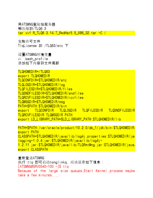
用ATSMNG登陆站服务器解压缩到/TLQ6.3tar xvf R_TLQ6.3.14.7_RedHat5.5_X86_32.tar -C /复制许可文件TlqLicense 到 /TLQ63/etc 下设置ATSMNG环境变量vi .bash_profile添加如下内容到文件尾部TLQHOMEDIR=/TLQ63export TLQHOMEDIRTLQCONFDIR=$TLQHOMEDIR/etcTLQLOGDIR=$TLQHOMEDIR/logTLQFILESDIR=$TLQHOMEDIR/filesTLQSNDFILESDIR=$TLQHOMEDIR/sndfilesTLQRCVFILESDIR=$TLQHOMEDIR/rcvfilesTLQMSGDIR=$TLQHOMEDIR/msgPATH=$PATH:$TLQHOMEDIR/binexport TLQCONFDIR TLQLOGDIR TLQFILESDIR TLQSNDFILESDIR TLQRCVFILESDIR TLQMSGDIR PATHexport LD_LIBRARY_PATH=$LD_LIBRARY_PATH:$TLQHOMEDIR/libPATH=$PATH:/var/oracle/product/10.2.0/db_1/jdk/bin:$TLQHOMEDIR/java/bin export PATHCLASSPATH=$TLQHOMEDIR/java/lib/log4j.properties:$TLQHOMEDIR/java/lib/tlc logging-1.0.4.jar:$TLQHOMEDIR/java/lib/log4j-1.2.11.jar:$TLQHOMEDIR/java/lib/TLQRmtMng.jar:$TLQHOMEDIR/java/lib:$TLQH export CLASSPATH重新登录ATSMNG执行 tlq 即可启动tonglinkq,应该显示如下信息:[ATSMNG@SRV0540-100 ~]$ tlqBecause of the large size queues,Start Kernel process maybetake a few minutes....[ATSMNG@SRV0540-100 ~]$ TongLink/Q start OK !执行export DISPLAY=133.1.1.151:0.0tlqmng进行配置,需要133.1.1.151上执行 Xmanager-Passive,节点名称为Station054801; 0548为收费站站号,01为序号,默认为01 Station045801Station:固定,收费站为Station0458:收费站站号01:序号上级节点固定位ETCCenter01(133.1.1.33)和ETCCenter02(133.1.1.34)发送队列为 StationSND接收队列为 StationRCV确定后,需要重新启动tlqtlq –cstop 停止服务tlq 启动服务切换至 root用户,修改 /etc/init.d/atsserver 启动脚本,添加tlq 启动脚本start)echo "Starting Spy for ATSServer ... "echo "-------------------------------------------------" >> /var/log/Spydate +" %T %a %D : Starting Spy for ATS server as part of system up." >> /var/log/Spyecho "-------------------------------------------------" >> /var/log/Spysu - ATSMNG -c "nohup /TLQ63/bin/tlq &" >> /var/log/Spysu - ATSMNG -c "nohup /ATSSERVER/BIN/Spy>>/dev/null &" >> /var/log/Spyecho "Done."/ATSSERVER/CONFIG/config.ini 尾部增加如下内容[MsgETC]DEFDB = </ATSSERVER/MsgETC/xmldef.db> #文法表XMLDB = </ATSSERVER/MsgETC/xmlqueue.db> #临时队列名称INQUEUE = <DataRecvXML> #输入队列 fmqTLQSEND = <StationSND> #输出队列 tonglink/qTLQRECV = <StationRCV> #输入队列 tonglink/qMSGMAX = <100> #每次最大放入的消息数量,然后等应答或超时后重放MSGVTIME = <600> #消息有效期 单位s MSGRTIME = <1200> #等待消息应答时间,超过后将重发单位sMSGDTIME = <1> #已经上传的消息保留时间,超过后将从数据库删除。
冠林分支解码器安装说明

冠林分支解码器安装说明
冠林分支解码器是一款高性能的视频解码器,可以支持多种视频格式,包括H.264、H.265、MPEG-2、MPEG-4等。
它可以提供高质量的视频解码,并且可以支持多种视频输出模式,如HDMI、VGA、YPbPr等。
安装冠林分支解码器非常简单,只需要几步就可以完成。
首先,将冠林分支解码器插入电视机的HDMI接口,然后将电视机的输出接口连接到冠林分支解码器的输入接口,最后将冠林分支解码器的输出接口连接到显示器的输入接口。
安装完成后,可以使用冠林分支解码器播放视频,只需要在电视机上选择视频源,然后在冠林分支解码器上选择视频输出模式,就可以播放视频了。
总之,安装冠林分支解码器非常简单,只需要几步就可以完成,可以提供高质量的视频解码,并且可以支持多种视频输出模式,是一款非常实用的视频解码器。
IDL系统与VSC-L30的安装、维护和使用指南说明书

1 SafetyThe IDL System and the VSC-L30 must be installed, commis-sioned and serviced only by adequately qualified personnel and in line with electrical engineering requirements. Read the Quickstart of VSC-L30 and Ruler E before starting the installation and make sure the Operating Instructions for the IDL system can be accessed during installation.Risk of injuries due to electrical current!The VSC-L30 is connected to the power supply (100 to 264 V AC/50 to 60 Hz).b Observe current safety regulations when working with electrical equipment.b Make sure the equipment has been deenergized before performing any installation work.2 Product SpecificationThe IDL system for item detection performs an analysis of letters and parcels on continuous belts, tilt trays and cross belt conveyor systems.IDL uses data from a Ruler E, which is mounted above the conveyor system. The Vision System Computer, VSC-L30 is used to analyze image data and communicate of results in the IDL System. Inside the VSC-L30 an iPC and a MSC800 control unit is mounted. In the VSC-L30 iPC, the Ruler E data is compared to a background reference where the difference is subjected to image processing that determines the presence of objects.When objects are detected the result values are calculated and reported to the MSC800 controller unit. Triggers,Encoders and other SICK devices in the same installation are also connected to the MSC800. When all results are ready the MSC800 sends the final result message to the client control system.3 System RequirementsPC for configuration and remote access of IDL:b PC Pentium III 500MHz minimumb RAM: 512 MB minimum (1 GB recommended)b Windows XP Professional SP3,Windows 7 Professional (32 / 64 bit)b Free disk space: 400 MB minimumb Monitor: 800 x 600 px, minimum 256 colors (65,536 colors (16 bit Hi color) recommended)b Ethernet card 100 Mbit/s or faster b USBFor access directly to the Ruler please see requirements for Ranger Studio in the Operating instructions.4 InstallationA thorough assembly and installation guide is included in the Operating Instructions.Important during installation:b Ensure that all laser safery requirements for the Ruler E camera is fulfilled. See the Ruler E user documentation for more information.b The laser of the Ruler may be activated as soon as the Ruler E is powered on. Avoid direct exposure to the laser beam. Avoid looking at the laser reflections.b Triggering parameters can be used to delay trigs for up to a cell length. The constraints of the triggering parameters should be considered when placing the photoelectric switch.b When delivered, the VSC-L30 is prepared for running in cell mode. If you intend to use the system in continuous mode, move the cables going to the encoder converter from OUT_2 and OUT_3 on the MSC800 to INC_1 and INC_2 respectively.b If the photoelectric switch or encoder is power supplied from the MSC800, make sure that the DIP switches SGND_4 - GND or SGND_5 - GND are set to ON.5 CommissioningThe IDL system must be commissioned by adequately quali-fied personnel only.The following software is used for the commissioning:b Ranger Studio Installed on the iPC b IDL application Installed on the iPC b SOPAS Download from , and installon the PC used for configuration.In-depth IDL Operating instructions are available for download from SICK. Access is given upon purchase of an IDL system.6 Service and Maintenanceb Spare parts for the devices that are present in the Item Detection system are handled as standard SICK products (Ruler E, iPC, MSC800, Ethernet switch, power supply).7 Further InformationSICK uses standard IP technology for its products, e.g. IO Link, industrial PCs. The focus here is on providing availability of products and services. SICK always assumes that the integrity and confidentiality of data and rights involved in the use of the above-mentioned products are ensured by customers themselves. In all cases, the appropriate security measures, e.g. network separation, firewalls, antivirus protection, patch management, etc., are always implemented by customers themselves, according to the situation.For more information on the Item Detection system, please refer to the Operating Instructions.For support issues, please contact your local sales office.More product and order information is also available on:Vision System Computer8014729 ∙ 2011-11All rights reserved Subject to change without prior noticeQ u i C k S ta r tAustraliaPhone +61 3 9497 4100 1800 334 802 – tollfree E-Mail **************.au Belgium/LuxembourgPhone +32 (0)2 466 55 66******************BrasilPhone +55 11 3215-4900******************.brCanadaPhone +1(952) 941-6780 1 800-325-7425 – tollfree **********************Ceská RepublikaPhone +420 2 57 91 18 50******************ChinaPhone +852-2763 6966******************.hk DanmarkPhone +45 45 82 64 00******************DeutschlandPhone +49 211 5301-301***************************EspañaPhone +34 93 480 31 00******************FrancePhone +33 1 64 62 35 00******************Great BritainPhone +44 (0)1727 831121******************.uk IndiaPhone +91–22–4033 8333*************************IsraelPhone +972-4-999-0590***************************ItaliaPhone +39 02 27 43 41******************JapanPhone +81 (0)3 3358 1341*********************MagyarországPhone +36 1 371 2680********************NederlandsPhone +31 (0)30 229 25 44******************NorgePhone +47 67 81 50 00************************ÖsterreichPhone +43 (0)22 36 62 28 8-0********************PolskaPhone +48 22 837 40 50******************RomâniaPhone +40 356 171 120 E-Mail **************RussiaPhone +7 495 775 05 30******************SchweizPhone +41 41 619 29 39*********************SingaporePhone +65 6744 3732***********************.sg South AfricaPhone +27 11 472 3733****************************.za South KoreaPhone +82-2 786 6321/4************************SlovenijaPhone +386 (0)1-47 69 990********************SuomiPhone +358-9-25 15 800******************SverigePhone +46 10 110 10 00******************TaiwanPhone +886 2 2375-6288********************.tw TürkiyePhone +90 216 528 50 00*******************.tr United Arab Emirates Phone +971 4 8865 878******************USA/MéxicoPhone +1(952) 941-6780 1 800-325-7425 – tollfree **********************More representatives and agencies atBCabinet Dimensional Drawings [mm (inch)]Cable Entries1 234 51 4 x M fitting, metal, M16 x 1.5 (0.06 inch)55 x M fitting, metal, M16 x 1.5 (0.06 inch)(0.12 ... 0.28 inch)Ruler E Encoder cable, M12 8-pin - open 5 m a6029331Ruler E Gigabit Ethernet cable, Cat. 6, 5 m c 6032321Other cable lengths are availableDiPC – Ruler network 192.168.0.1interfacehalf/full duplexEFTechnical DataCablesDevice IP Addresses2(BR)7(BL)1(W)ONOFFS G N D _5 - G N D S G N D _4 - G N D1(W)4(Y)2(BRN)3(GRN)145827X4.1X4.2I N C _1I N C _2INC X4X4.7X4.8+24 V S G N D _4X5.1T R G _1TRIGGER X5X5.7X5.8+24VS G N D _5X7.2O U T _2OUT X7Trig 124V 0V A B24VGNDCONVErtErruLEr E – CONNECtOrSMSC800 – BLOCkSPower connector Encoder connectorPhotoelectric switchEncoder2(BR)7(BL)1(W)ONOFFS G N D _5 - G N D S G N D _4 - G N D1(W)4(Y)2(BRN)3(GRN)145827X5.1T R G _1TRIGGER X5X5.7X5.8+24VS G N D _5X7.2X7.3O U T _2O U T _3OUT X7X7.4O U T _4Trig 124V0VCONVErtErruLEr E – CONNECtOrSMSC800 – BLOCkSPower connector Encoder connectorPhotoelectric switch(Colors are valid for cable types STL-1208 and DOL-1208 respectively)。
DocuPrint P115 b维修手册(第一版)无密码
4.6 Laser Unit问题故障排除 ...................................................... 1-31 4.6.1 Laser unit故障 ...................................................... 1-31
1-23 1-24 1-24 1-24 1-25 1-25 1-26 1-26
4.2.20 重影 ................................................................ 1-26 4.2.21 图像模糊 ............................................................ 1-27
4.4.4 4.4.5 4.4.6
Drum错误 ............................................................ 1-29 无法检测到Drum unit ................................................. 1-30 更换Drum unit (更换新Drum unit后,LED显示仍提示更换Toner cartridge)... 1-30
• 当某页面作废时 (例如被替代页面取代), 请焚烧或撕碎该页面以将其销毁。
• 使用时请注意,应将手册保管好,避免遗失 或破损。
• 修订和修改信息 当出现设计变更或本维修手册发生修改时,在载 入最新的维修手册之前,将可能作为补充信息, 发行海外技术信息或海外维修公告。
注意
在得知备用零件号码的变更及规 格调整等重要的变更信息后,须 立即反映在本维修手册内的相应 页面。
LSV LSVG 安装手册说明书

INSTALLATION MANUALLSV | LSVGEN 199923Installation of support brackets:Generally, the type of support bracket depends on local require-ments.The support brackets are either bolted or welded; support centers are 2000 mm (6‘-6“). Slotted holes in the brackets and hangerstuds allow for horizontal and vertical adjustment/alignment.We do recommend our standard brackets, which can be boltedd irectly to the I-beam.Installation of conductor system with plug-in jointsThe plug-in type connectors serve to compensate for the different expansion and contraction of the aluminium housing and the copper conductors. Use telescope sections for runs exceeding 200 m.Where you start depends on the site conditions. Install one sliding hanger to one of the support brackets. Then slide another hanger over the top profile of one Powerail standard section and push the Powerail into the first hanger.Install the second hanger to the next bracket. In order to facilitate the further mounting procedure put locating clamps close to the first hanger, forming an anchor point. Make sure that all other hangers are in a perpenticular position and not twisted, so that the Powerail can slide for expansion and contraction.Prepare the next Powerail section with plug-in connectors and push pegs (stagger the pins for easy insertion into the end of the section already mounted).Push sliding hangers on to this second Powerail section and install on the next two support brackets.Curves, switches and other specials should be installed first. Position line feed section as close as possible to power supply outlet. The connecting cables must not restrict free movement of the conductor system.photo 1LSVGlong lipsketch 1Long lip side of the LSV and LSVG housing should always be mounted towards the track.Now push this Powerail section towards the first section until the plug-in connectors and the grooved push pegs engage. Careful work in this stage is most important for proper function of the system.Ensure perfectly closed joint by using wooden block and hammer from the blank end of the second Powerail section.Attach joint fish plates and tighten properly.Fit premounted yellow-green grounding cable over the joint and bolt to the adjacent Powerail section.Continue this installation procedure for all other Powerail sections.Remove the two locating clamps from the first installed section and fit them next to one of the hangers in the approx. center of the run-way.Make sure that hangers are not placed directly on joints. Minimum spacing between hangers and joint plates should be 100 mm (4 inch-es). If necessary rearrange support brackets.Installation of the Powerail with bolted joints:The bolted joint Powerail version requires expansion joints approx. every 50 meters in order to compensate for the different expansion and contraction of the aluminium housing and the copper conduc-tors.Install the first Powerail standard section as described.Push the preassembled connecting pieces over the copper conduc-tors at one end of the Powerail section (photo 6).Now install the second Powerail section and push tightly (as photo 4) towards the first section after inserting the grooved pegs for aligning the aluminium housing.Slide the connecting pieces exactly half way over the adjoining cop-per conductors and tighten hardware (photo 7).photo 2 photo 3photo 4photo 5photo 6photo 7 photo 84Place joint covers over joint and tighten properly. Fit grounding cable as photo 8.Install all other Powerail sections the same way. Positioning of the locating clamps, insertion of collectors and power connection as de-scribed.Insert the current collectors from either end of the Powerail system. Make sure that the safety key is facing the short lip of the alumi-nium housing. Trolleys will only fit one way to avoid phase reversing. Allow for sufficient manual test runs. The collector trolley should run smoothly.Connect collector cables and tow arm to the machinery.Connect current supply cables to power feeds. Cables, switches and fuses to be supplied by others.After insertion of all required collectors secure Powerail end caps.Follow exactly the factory prepared layout plan when installing cur-ves, switches, transfers etc.sketch 2photo 9photo 10photo 11photo 12photo 1356Installation of Neoprene Sealing Strip “D”Each LSV-LSVG consignment with sealing strip does include a moun-ting trolley.Start from one end of the Powerail system, pressing approx. 20 mm (~1“) sealing strip by hand into the profile.Insert the mounting trolley.Bend sealing strip towards the Powerail slot and pull trolley through, now pressing the entire length of the sealing strip into its proper position (photo 12).Systems exceeding 50 m length will require a coupling for the sealing strip (see sketch).The sealing strip will be interrupted in areas for transfer guides, tele-scope and expansion joint sections. In this case cut the ends of the sealing strip oblique and tighten with fastener (see adjacent sketch).For clearance of end caps cut back the sealing strip by approx. 60 mm.Inspect sealing strip for proper fit and adjust where necessary.photo 14photo 15photo 167Sketch 5Terminal BoxTerminal Box 1-core cable > 2,5 mm²by customerSupply voltageHeating cable in copper tubeSketch 4joint sleeveheating cable Installation of heating cables1.Pull the heating cable into the factory assembled copper tube. Use a thin stiff wire and pull the heating cable through the entire length of your heating section (two men required for pulling from one end and pushing from the other end). Important: Smooth insertion of the heating cable and no kin-king.2.Connect the heating cable at the factory assembled terminal box. The heating cable comes 1 m longer than required for the heating section, so that you can cut a suitable connecting end.Prepare the connecting end per adjacent sketch as follows:a. Remove the sheathing for about 40 mm.b. Cut back the insulation for about 12 mm and bend the wireper sketch.c. Prepare the 1.5 sqmm connecting cable, cut back the insu -lation for approx. 6 mm.d. Both, the heating cable and the connecting cable, now to bejointed in a standard sleeve, using a crimping tool.e. Push shrink-tubing over the joint and braise carefully withsmall lighter flame.f. Cut the 1.5 sqmm connecting cable to suit into the terminalbox. Remove 6 mm insulation and connect to the terminal clamp.3.WiringConnect the supply cable (220, 380 V) to the terminal box. A considerable shortening of the hea-ting cable may causeo verheating and burning – so never cut the heating cable too much. The supply cable, switches, fuses and temperaturer egulating devices to be supplied by the customer. When using thermostats for automatic regulation, these should be adjusted at +2°C/–3°C to put the heating system in operation.Paul Vahle GmbH & Co. KG Westicker Str. 5259174 KamenGermanyTel.: +49 2307 704-0 Fax: +49 2307 704-444*************。
JBL Synthesis SDR-35 SDP-55 HDMI 2.1 固件更新指南说明书
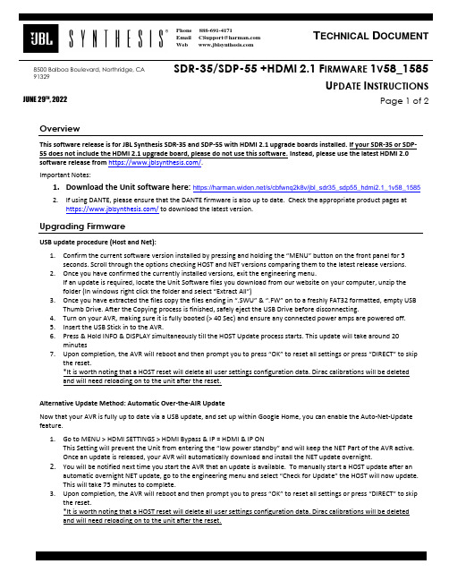
8500 Balboa Boulevard, Northridge, CA 91329 SDR-35/SDP-55+HDMI2.1F IRMWARE 1V58_1585U PDATE I NSTRUCTIONSJUNE 29TH, 2022Page 1 of 2OverviewThis software release is for JBL Synthesis SDR-35 and SDP-55 with HDMI 2.1 upgrade boards installed. If your SDR-35 or SDP-55 does not include the HDMI 2.1 upgrade board, please do not use this software. Instead, please use the latest HDMI 2.0software release from https:///.Important Notes:1.Download the Unit software here: https:///s/cbfwnq2k8v/jbl_sdr35_sdp55_hdmi2.1_1v58_15852.If using DANTE, please ensure that the DANTE firmware is also up to date. Check the appropriate product pages athttps:/// to download the latest version.Upgrading FirmwareUSB update procedure (Host and Net):1.Confirm the current software version installed by pressing and holding the “MENU” button on the front panel for 5seconds. Scroll through the options checking HOST and NET versions comparing them to the latest release versions.2.Once you have confirmed the currently installed versions, exit the engineering menu.If an update is required, locate the Unit Software files you download from our website on your computer, unzip thefolder (In windows right click the folder and select “Extract All”)3.Once you have extracted the files copy the files ending in “.SWU” & “.FW” on to a fre shly FAT32 formatted, empty USBThumb Drive. After the Copying process is finished, safely eject the USB Drive before disconnecting.4.Turn on your AVR, making sure it is fully booted (> 40 Sec) and ensure any connected power amps are powered off.5.Insert the USB Stick in to the AVR.6.Press & Hold INFO & DISPLAY simultaneously till the HOST Update process starts. This update will take around 20minutes7.Upon completion, the AVR will reboot and then prompt you to press “OK” to reset all settings or press “DIRECT” to skipthe reset.*It is worth noting that a HOST reset will delete all user settings configuration data. Dirac calibrations will be deletedand will need reloading on to the unit after the reset.Alternative Update Method: Automatic Over-the-AIR UpdateNow that your AVR is fully up to date via a USB update, and set up within Google Home, you can enable the Auto-Net-Update feature.1.Go to MENU > HDMI SETTINGS > HDMI Bypass & IP = HDMI & IP ONThis Setting will prevent the Unit from entering the “low power standby” and will keep the NET Part of the AVR active.Once an update is released, your AVR will automatically download and install the NET update overnight.2.You will be notified next time you start the AVR that an update is available. To manually start a HOST update after anautomatic overnight NET update, go to the engineering menu and select “Check for Update” the HOST will now update.This will take 75 minutes to complete.3.Upon completion, the AVR will reboot and then prompt you to press “OK” to r eset all settings or press “DIRECT” to skipthe reset.*It is worth noting that a HOST reset will delete all user settings configuration data. Dirac calibrations will be deletedand will need reloading on to the unit after the reset.8500 Balboa Boulevard, Northridge, CA 91329 SDR-35/SDP-55+HDMI2.1F IRMWARE 1V58_1585U PDATE I NSTRUCTIONSJUNE 29TH, 2022Page 2 of 2Fix list (v1.58_1585):IMS21059: With Z2 on and Z1 off the front panel display back light remains onIMS22966: Add NET recovery via USB mode featureIMS23629: Make Dante and Analogue Direct mutually exclusive.IMS24389: Intermittent audio dropouts with PS5Fix list (v1.54_1496):Fix issue with streaming service endpointFix list (v1.54_1426):First Release.。
先锋蓝光组合音响 BD-HTS4_V59.59.06 固件升级程序操作说明说明书

蓝光组合音响蓝光组合音响固件固件固件升级程序的操作说明升级程序的操作说明注意注意::先锋固件程序及其对应软件下载只适用于中国大陆地区,并且只供指定型号使用,更新前请确认固件程序及软件是否适用于指定地区及型号,如使用不正确或不适当固件程序及软件,先锋电子(中国)投资有限公司恕不负责。
警告警告!!!升级过程需时约10分钟,其间请勿拔去电源线或按下“STANDBY/ON ”键,直至更新完毕,更新完毕后机器将自动关机。
更新过程中请勿对蓝光组合音响进行操作。
如果更新过程中出现异常,可能说明蓝光组合音响主机无法正常运作而需要维修。
以下升级程序的操作说明以下升级程序的操作说明只适用于只适用于HTZ-727BD ,HTZ-828BD ,HTZ-222BD ,HTZ-323BD ,HTZ-FS121BD ,HTZ-FS122BD ,HTZ-SB123BD 的型号A 请先确认蓝光组合音响主机的现有固件程序版本:(需使用蓝光组合音响主机的遥控器来进行操作)1. 按下“STANDBY/ON ”开启主机电源。
* 如果您正在播放碟片,请按停止键直到电视机屏幕上出现PIONEER 字样。
2. 按“Home Menu ”按钮进入主菜单。
3. 屏幕上选“初始设定”,按“ENTER ”进入。
4. 屏幕上选“选项”,按“ENTER ”进入。
5. 屏幕上选“系统信息”,按“ENTER ”进入。
6. 屏幕上选“下一个画面”,按“ENTER ”进入。
7. 检查固件版本信息。
如果固件版本信息为V59.59.06或者更高版本,则不用进行程序升级。
如果固件版本信息低于V59.59.06,请继续BB 请先从中国先锋网站下载相关升级固件到电脑中,名称为:BD-HTS4_V59.59.06.zipC. 升级需要通过USB 设备完成(U 盘,以下简称USB )。
USB 需满足以下条件:-USB 2.0-容量为128MB 及以上注意:1、复制固件程序到USB 之前,请确认USB 中没有其他内容。
- 1、下载文档前请自行甄别文档内容的完整性,平台不提供额外的编辑、内容补充、找答案等附加服务。
- 2、"仅部分预览"的文档,不可在线预览部分如存在完整性等问题,可反馈申请退款(可完整预览的文档不适用该条件!)。
- 3、如文档侵犯您的权益,请联系客服反馈,我们会尽快为您处理(人工客服工作时间:9:00-18:30)。
LS-QL 固件安装图片介绍
此文档为青州小熊原创,更多资料请关注小熊的网站:
1 .设置网卡IP
2.打开文件夹内的TFTP Boot recovery文件夹,点击TFTP.Boot
3.运行后,放上硬盘,一个或二个,开机,注意一下电源灯红色闪烁, 硬盘指示灯绿色时,按下FUNCTION 键后,观察电源指示灯应变成蓝色。
后,面板指示灯,为蓝色和绿色。
显示找到了LS-QL IP 网关,下一步就可以更新固件了。
6.点击文化夹中的LSQL-111文件夹,进入LS-QL的固件升级目录,
7,点击运行LSUpdater,点击Updata
8,出现一个提示框,大体意思就是要不要格式化硬盘,选是,就可以格式化硬盘并分区了。
9,接下来,就自动更新固件
10.大约 10分钟,结束出现下面的图片。
11.实际这样已OK完成了。
点一下点击TFTP Boot recovery文件夹中的 NasNavi 图标,
如打开了,就点一下那个Refresh,IP变成169.254.99.179就代表OK了。
12.拨下网线,接到路由器上,就可以管理盒子了(记的把刚才主机修改的IP修改回原样)。
13.安装新版NASNavigator2 联接器,管理你的盒子。
点击图标右键打开WEB设置
14.初始页面为日文,进入后,我们要修改成中文,再比着LS-QL 的PDF文档操作就行了,用户名:admin 密码:password
15.进入设置页面后,点一下右边框中的基本,向下拉菜单,找到言语设定,表示言语选择中国语简体或别国语言,下面的那个windows 言语也调到简体中国(CP936)点下面的设定。
进入后,就可以比着PDF文档,设置了。
