GT22L型磁保持继电器Latching HV Relays 15kV GTVAC
霍尼韦尔小型通用型继电器 工业控制元器件 GR系列 CR(T)系列 SR系列 使用说明书

选型指南 适合应用
参数范围
一般应用,适用于中等负载
额定电流小于 12A 一般冲击电流小于 30A
灯负载,感性负载和部分容性 很高冲击电流,最大 120A
负载
控制负载,传感器负载
最小导通掉电流小于 5mA
2
线圈参数及附件保护电路选型指南
线圈参数 线圈阻抗及特性 线圈的阻抗可以用电阻表测得,阻值是在标准规定 23ºC 测得。 误差范围为 ±10%。对于交流线圈而言,由于自感应原因,线 圈电流和阻值会不匹配。在 230V 时,自感应系数会达到 90H。 当线圈断开时,自感应带来的感应电压会影响开关源。
选型指南 释放电压 直流继电器 10%Un 保证释放 交流继电器 15%Un 保证释放
保护电路 保护类型
示意图
二极管保护
适用线圈
响应时间
直流线圈
4 倍Байду номын сангаас放时间
选型指南 适用场合
参数范围
用于阻尼在继电器释放时 保护等级 III (2000V) 至高至 60VDC 产生的瞬态能量(感应断 保护等级 IV (4000V) 61 至 250VDC 路电压)
接件
4
GR 系列小型中间继电器
p 2CO-5A,4CO-5A p 标配测试按钮及机械指示窗 p 标配 LED 状态指示灯
PGR 系列小型中间继电器插座
p 标准式插座 PGR-E p 分离式插座 PGR-S
AGR 系列小型中间继电器附件
p 保护卡簧 p 浪涌保护模块 p 标记牌
Page 6
CR(T) 系列透明外壳紧凑型中间继电器
性能曲线 4CO 电寿命曲线图
1000
ۉం൸၍ Electrical life
穆勒-元器件选型手册
AC/DC100~250V(AS和AN型) ·DC24~48V(AH型)
DC24~60V(AS和AN型)
基本的保护功能(长延时/短延时/瞬时/接地故障)不带 控制电源一样可以正常操作
·可用
·可用
·N型
·N型
电话:028-86703201 传真:028-86703203
2009.11 版本
如有改动,恕不事先通知
样本编码10310000784
2009.11 印刷
上海
电力产品总图
超高压GIS
中压环网柜(CB型)
40.5kV 开关柜
中压环网柜
PROMEC 40.5kV 真空断路器
户外柱上负荷开关 户外环网开关柜
变压器
金属封闭开关柜
箱式变电站
负荷开关
变压器
凯装式金属封闭开关柜
GIPAM 115 综合数字保护装置
PROMEC 真空断路器
真空接触器
GIMAC-II plus 电机保护控制装置
GIPAM 2200 综合数字保护装置
DPR 综合数字保护装置
工控产品 (接触器、热过载继电器、电动机启动器)
Susol空气断路器
欠压线圈额定电压 不带欠压线圈
*UVT延时模块可用于AC/DC48V以上
附件
脱扣报警触头1a+ 手动复位按钮 脱扣报警触头2a+ 手动复位按钮 脱扣报警触头1a+ 手动复位按钮+远程复位开关 脱扣报警触头1a+ 手动复位按钮+远程复位开关 AL+自动复位 A2+自动复位 A3+自动复位 A4+自动复位 计数器 完全储能通讯触点 分合闸按钮锁 机械联锁 门联锁或机械操作位置开关 圆柱锁 三锁两钥匙 双重锁定钥匙锁 准备合闸开关 温度报警 自动释能机构 双分励线圈
Spartan 三角形锁定开关说明书

DescriptionThe Spartan is a positive mode, tongue operated guard locking interlock switch that locks a machine guard closed until power is isolated and ensures that it remains isolated while the guard is open. It is available in two contact configurations: two safety (N.C.) contacts and one auxiliary (N.O.) contact or three safety (N.C.) contacts. The Spartan head has two entry slots and it can be rotated to provide four actuator entry points. A blanking plug is provided to seal the unused slot.The guard may only be opened when a signal is applied to the Spartan’s internal solenoid which releases the lock mechanism. Therefore the Spartan is ideal for machines which do not stop immediately or where premature interruption of the machine could cause damage to tooling and components or cause an additional hazard.The locking mechanism withstands forces up to of 1200N (270lbs.) and an LED provides visual indication of switch status.A catch kit with actuator alignment is also supplied to relieve stress on the locking solenoid and to protect the unit from actuator damage due to poor guard alignment. Manual release points with security screws or special key allow the locked Spartan to be released in the event of total power failure on a machine.Features•Power to release•Lid mounted status indication•High locking force—1200N (270lbs.)• 2 N.C. & 1 N.O. or 3 N.C.•Rotatable head: 4 possible key entry slotsTypical ApplicationsNote: Lift-off guards require good alignment when usingtongue actuated interlock switches.IMPORTANT: It must not be possible to lift the guardwithout actuating the interlock. An interlock on either sidemay be required.Specifications➊Conductive pollution occurs, or dry, non conductive pollution occurs which becomes conductive due to condensation.Standards EN954-1, ISO13849-1, IEC/EN60204-1,NFPA79, EN1088, ISO14119, IEC/EN60947-5-1, ANSI B11.19, AS4024.1 Category Cat. 1 Device per EN954-1Dual channel interlocks suitable forCat. 3 or 4 systemsApprovals CE marked for all applicable directives,cULus and TUV NordSafety Contact 2 N.C. or 3 N.C. direct opening action Utilization Cat.AC (Ue)(le)DCAC 15500V 250V 100V1A 2A 5A250V/0.5A 24V/2AMaximum Switched Current/Volt/Load500V/500VAThermal Current (lth)10AMin Current5V 5mA DCSafety Contact Gap>2mmRtd. Insulation Voltage500VRtd. Impulse withstand Volt2500VAuxiliary Contacts 1 N.O.Pollution Degree ➊3Max Actuation Speed160mm/second (6.3 in/sec)Max Actuation Frequency 1 cycle/secondCase Material UL Approved glass filled polyester Actuator Material Stainless steelProtection IP 67Conduit Entry 1 x M20 or quick disconnect style Operating T emperature-20°C to 60°C (-4°F to +140°F)Fixing 2 x M5Mounting Any positionMechanical Life1,000,000 operationsElectrical Life1,000,000 operationsWeight260g (0.57 lb)Colour RedMax Holding Force1200N (270lbs)Min Operating Radius175mm (6.9in)LED Indication Solenoid monitor LEDPower Supply24V AC/DC, 110V AC, 230V AC(solenoid)Solenoid Power Typically 7W 100% EDProduct SelectionAccessoriesActuatorSolenoid Voltage ContactsCatalogue NumberSafety Aux.M20 Conduit M20 Conduit/1/2in Adaptor Quick Disconnect Standard 24 V AC/DC2 N.C. 1 N.O.440G-S3*******G-S3*******G-S360583 N.C.—440G-S3*******G-S3*******G-S3******* V AC/DC2 N.C. 1 N.O.440G-S3*******G-S3*******G-S360603 N.C.--440G-S3*******G-S3*******G-S3*******V AC/DC2 N.C. 1 N.O.440G-S3*******G-S3*******G-S360623 N.C.—440G-S36011440G-S36049440G-S36063Mating cable 2m (6.5ft). See page 15-13 for details and additional lengths.889M-F12X9AE-2DescriptionFor Dimensions refer to pageCatalogue NumberReplacement Actuator with CatchRetainer and Guide14-4440G-A36050Emergency Override 14-4440G-A36026Approximate Dimensions—mm (inches)Dimensions are not intended to be used for installation purposes.Typical Wiring Diagrams2 N.C. + 1 N.O.Actuator withdrawal distancefrom full insertion3 N.C.Application Details。
智能电动机保护器使用说明书
5.7 250A 电流互感器外形尺寸..................................................................................................................................................12 5.7 800A 外置电流互感器外形尺寸..........................................................................................................................................13 5.8 漏电流互感器外形尺寸.......................................................................................................................................................13 5.9 显示模块外形尺寸...............................................................................................................................................................14 6 操作指南....................................................................................................................................................................................... 15 6.1 90L 显示模块面板................................................................................................................................................................15 6.2 显示操作说明........................................................................................................................................................................ 15 6.3 面板设置信息及菜单概述...................................................................................................................................................16 7 保护功能.....................................................................................................................................................................................24 7.1 过载保护................................................................................................................................................................................ 24 7.2 断相/不平衡保护.................................................................................................................................................................. 25 7.3 剩余电流保护(接地/漏电).............................................................................................................................................. 25 7.4 堵转保护................................................................................................................................................................................ 25 7.5 阻塞保护................................................................................................................................................................................ 25 7.6 欠载(欠流)保护...............................................................................................................................................................26 7.7 起动超时保护........................................................................................................................................................................ 26 7.8 欠压保护...............................................................................................................................................................................26 7.9 过压保护...............................................................................................................................................................................26 7.10 7.11 7.12 7.13 7.14 8 欠功率保护.........................................................................................................................................................................26 相序保护.............................................................................................................................................................................26 外部故障保护.....................................................................................................................................................................26 温度保护.............................................................................................................................................................................26
现代重工低压断路器
利亚、亚洲、非洲在内的全球产业现场,随处可见现代重工电气设备的身影。 引领21世纪潮流的现代重工电气,以真挚的爱、坚韧不拔的意志,将一如既往地研发
电力产业之高精尖产品,以最高的技术、最好的品质满足客户要求,把企业建成国际化的
电气产业先锋,为创造美好未来奉献出我们的一切。
HYUNDAI HEAVY INDUSTRIES (CHINA) ELECTRIC CO.,LTD. is an independent corporation, built by HYUNDAI HEAVY INDUSTRY CO., LTD. locating in No.9 Hyundai Road, Xinba Scientific and Technologic Zone, Yangzhong city, Jiangsu Province, which covers an area of 170,000m2. The total investment is$60,000,000 , and HYUNDAI HEAVY INDUSTRY is responsible for HYUNDAI HEAVY INDUSTRY (CHINA) product technology. Main manufacture and testing facilities are imported from America, Italy, Japan, Korea, Sweden, which ensure production quality and immediate delivery. There are three workshops: medium voltage CB workshop, HV CB workshop, SWGR workshop. Main products: 72.5~1000kV SF6 GIS, 0.4kV~40.5kV Switchgear, 40.5kV SF6 C-GIS, marine switchgears and consoles, VCB, ACB, MCCB, MS, MCB, ATS and so on.
dc-bank系统几种技术线路的比较
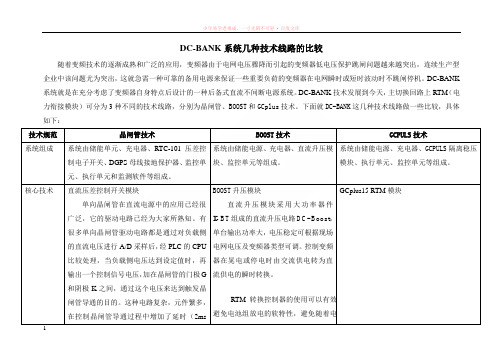
DC-BANK系统几种技术线路的比较随着变频技术的逐渐成熟和广泛的应用,变频器由于电网电压骤降而引起的变频器低电压保护跳闸问题越来越突出,连续生产型企业中该问题尤为突出,这就急需一种可靠的备用电源来保证一些重要负荷的变频器在电网瞬时或短时波动时不跳闸停机。
DC-BANK 系统就是在充分考虑了变频器自身特点后设计的一种后备式直流不间断电源系统。
DC-BANK技术发展到今天,主切换回路上RTM(电力衔接模块)可分为3种不同的技术线路,分别为晶闸管、BOOST和GCplus技术。
下面就DC-BANK这几种技术线路做一些比较,具体如下:技术规范晶闸管技术BOOST技术GCPULS技术系统组成系统由储能单元、充电器、RTC-101压差控制电子开关、DGPS母线接地保护器、监控单元、执行单元和监测软件等组成。
系统由储能电源、充电器、直流升压模块、监控单元等组成。
系统由储能电源、充电器、GCPULS隔离稳压模块、执行单元、监控单元等组成。
核心技术直流压差控制开关模块单向晶闸管在直流电源中的应用已经很广泛,它的驱动电路已经为大家所熟知。
有很多单向晶闸管驱动电路都是通过对负载侧的直流电压进行A/D采样后,经PLC的CPU比较处理,当负载侧电压达到设定值时,再输出一个控制信号电压,加在晶闸管的门极G和阴极K之间,通过这个电压来达到触发晶闸管导通的目的。
这种电路复杂,元件繁多,在控制晶闸管导通过程中增加了延时(2ms BOOST升压模块直流升压模块采用大功率器件IGBT组成的直流升压电路DC- Boost,单台输出功率大,电压稳定可根据现场电网电压及变频器类型可调。
控制变频器在晃电或停电时由交流供电转为直流供电的瞬时转换。
RTM转换控制器的使用可以有效避免电池组放电的软特性,避免随着电GCplus15 RTM模块以上),因为A/D转换和CPU处理,都需要时间,而且因为电路复杂,增加了故障率,这种控制电路不但需要提供外部电源供电,而且在对晶闸管的门极加控制电压时还要进行隔离,否则因为晶闸管的回路电压过高,会损坏控制电路。
CT81-15KV-222高压瓷片电容规格书

The wafer diameter
08=8(mm)
◆ About Y5T ceramic Y5T 材质是一种性能
Y5T 电容变化电压关系曲线
Y5T Capacitance change vs Voltage
◆注意事项
PRECAUTIONS
(1) 运输和储存
(1) During transportation and storage
•请避免在高温或高湿度或淋雨状态下运输或 • Do not transport or store where the capacitor will be exposed to high temperature or high
-55 -40 -20 0
Temperature °C
20 40 60 80 100 125
Y5T 电容变化温度曲线
Y5T Capacitance change vs Temperature
C
A
10
ΔC/C(%)
0
-10
-20
1
-30
2
3
Rated Voltage
0
20%
50%
70%
90% 100%
CT81 SERIES
HIGH VOLTAGE CERAMIC CAPACITORS LEAD RADIAL TYPE ( 15KVDC222M)
◆产品特性 Features
*低损耗 Low dissipation factor of 0.4% at 1 KHZ *高频特性 High frequency ≥100KHZ *过大电流 High current ≥5MA *高压特性好 High voltage ≥35KVDC *绝缘电阻大 High insulation resistance ≥300000MΩ *使用寿命长 Long life ≥10 years
变电所电气主接线图、配电干线系统图

西门子 S7-1200 功能安全手册 - 设备手册说明书
SIMATICS7S7-1200 功能安全手册设备手册Siemens AGDigital IndustriesⓅ 10/2022 本公司保留更改的权利 Copyright © Siemens AG 2022. 保留所有权利法律资讯警告提示系统为了您的人身安全以及避免财产损失,必须注意本手册中的提示。
人身安全的提示用一个警告三角表示,仅与财产损失有关的提示不带警告三角。
警告提示根据危险等级由高到低如下表示。
危险表示如果不采取相应的小心措施,将会导致死亡或者严重的人身伤害。
警告表示如果不采取相应的小心措施,可能导致死亡或者严重的人身伤害。
小心表示如果不采取相应的小心措施,可能导致轻微的人身伤害。
注意表示如果不采取相应的小心措施,可能导致财产损失。
当出现多个危险等级的情况下,每次总是使用最高等级的警告提示。
如果在某个警告提示中带有警告可能导致人身伤害的警告三角,则可能在该警告提示中另外还附带有可能导致财产损失的警告。
合格的专业人员本文件所属的产品/系统只允许由符合各项工作要求的合格人员进行操作。
其操作必须遵照各自附带的文件说明,特别是其中的安全及警告提示。
由于具备相关培训及经验,合格人员可以察觉本产品/系统的风险,并避免可能的危险。
按规定使用 Siemens 产品请注意下列说明:警告Siemens 产品只允许用于目录和相关技术文件中规定的使用情况。
如果要使用其他公司的产品和组件,必须得到 Siemens 推荐和允许。
正确的运输、储存、组装、装配、安装、调试、操作和维护是产品安全、正常运行的前提。
必须保证允许的环境条件。
必须注意相关文件中的提示。
商标所有带有标记符号 ® 的都是 Siemens AG 的注册商标。
本印刷品中的其他符号可能是一些其他商标。
若第三方出于自身目的使用这些商标,将侵害其所有者的权利。
责任免除我们已对印刷品中所述内容与硬件和软件的一致性作过检查。
然而不排除存在偏差的可能性,因此我们不保证印刷品中所述内容与硬件和软件完全一致。
煤矿安标新文件3D受控元件明细表

二〇 一〇 年七月二十二日
产品主要零(元)部件及重要原材料明细汇总表
目录
1 电气设备 .......................................................................................................................................................... 1 1.1 开关与起动器 ....................................................................................................................................... 1 1.1.1 矿用防爆低压交流真空馈电开关 .................................................................................................... 1 1.1.2 矿用隔爆型馈电开关 ........................................................................................................................ 1 1.1.3 矿用防爆高压配电装置 ...........................................................................................................
伊顿电子产品参考手册说明书

提供动力。
探索今天的伊顿。
我们提供:• 方案• • •动及动力总成解决方案马达控制设备命令和控制设备终端保护产品自动化和驱动产品134MOEM 市场综合样本目录2马达和线路控制设备伊顿拥有超过百年的接触器研发和制造经验,为用户提供至3185A 的线路控制解决方案,并提供不同系列的产品以满足用户的的多种要求Xstart 系列接触器:全球化的产品,提供包括UL 在内的主流认证,最高达3185安培(AC-1)的产品:• 独特的CT 型励磁机构,功耗更小;• 115A 以上集成电子线路板,降低功耗同时工作电压幅度更宽;• 580A 以上真空灭弧,应对严苛使用环境,业界最长预期寿命;• 提供本地化的XstartC 系列(认证情况请咨询当地销售办事处)。
D 系列接触器:本地化的产品,提供最高到500A 的高效控制和保护方案,应用于泵、风机、压缩机等场合,提供功能全面的辅助触点和宽幅的控制线圈电压选项。
• 齐全的线圈控制电压,185A 以上更提供交直流通用产品;• 全系列内置辅助触点• 百万次以上电气寿命• 使用温度-20 °C ~ +55 °CE 系列接触器:全球最小的电磁接触器之一,有效地利用空间,可靠性增强,材料使用更高效。
E 系列接触器额定值可至AC-3, 95A@400V ,最高工作电压高达660V ,体积小巧,却提供强大的性能。
• 百万次以上电气寿命• 690V 绝缘额定值• 最多可加装6个辅助触点模块• 常用交流控制电压及直流24VDC 线圈1马达控制设备目录电机控制产品 xStart C 接触器式继电器DILA..C 接触器DILM..C 过载继电器ZB..C电动机保护断路器PKZMC 电机控制产品 D 系列接触器 XTCD 热过载继电器 XTOD 电气行业解决方案 Eline 控制继电器 XTRG 接触器 XTCG热过载继电器 XTOD/XTOG电机控制产品 xStart C电机控制产品 D 系列电气行业解决方案Eline1接触器式继电器DILA..C目录系统概览 . . . . . . . . . . . . . . . . . . . . . . . . . . . . . . . . . . . . . . . . . . . . . . . . . . . . . . . . . . . . . . . . . . . . .本体DILA..C . . . . . . . . . . . . . . . . . . . . . . . . . . . . . . . . . . . . . . . . . . . . . . . . . . . . . . . . . . . . . . . . . .辅助触点模块 . . . . . . . . . . . . . . . . . . . . . . . . . . . . . . . . . . . . . . . . . . . . . . . . . . . . . . . . . . . . . . . .附件 . . . . . . . . . . . . . . . . . . . . . . . . . . . . . . . . . . . . . . . . . . . . . . . . . . . . . . . . . . . . . . . . . . . . . . . . .操作电压 . . . . . . . . . . . . . . . . . . . . . . . . . . . . . . . . . . . . . . . . . . . . . . . . . . . . . . . . . . . . . . . . . . . . .特性曲线,触点行程图 . . . . . . . . . . . . . . . . . . . . . . . . . . . . . . . . . . . . . . . . . . . . . . . . . . . . . . . .技术数据 . . . . . . . . . . . . . . . . . . . . . . . . . . . . . . . . . . . . . . . . . . . . . . . . . . . . . . . . . . . . . . . . . . . . .尺寸 . . . . . . . . . . . . . . . . . . . . . . . . . . . . . . . . . . . . . . . . . . . . . . . . . . . . . . . . . . . . . . . . . . . . . . . . .4极触点多种组合约定发热电流(I th )16A 交流与直流操作的产品尺寸相同直流操作的产品内置浪涌抑制器••••接触器式继电器DILA..C35791112131911接触器式继电器DILA..C说明121接触器式继电器DILA..C系统概览31接触器式继电器DILA..C系统概览4系统概览本体AC 或DC 操作电磁系统AC DC 可以扩展到8对触点反向互锁触点模块化系统螺钉连接和卡装手指接触防护螺钉端子第5页起抑制电路用于直流操作接触器式继电器的保护电路(所有直流型均内置)用于交流操作接触器式继电器的保护电路第32页起辅助触点模块23, 42或4极反向互锁触点第7页起124 – 400V, 50, 60, 50/60 Hz0.8 – 1.1 × U c 24 VA/3.4 VA 24 – 220 V DC0.8 – 1.1 × U c 于24 V :0.7 – 1.3 × U c 无附加辅助触点模块环境温度+40°C 3W/3W1接触器式继电器DILA..C本体5接线方式:螺钉端子触点N/O = 常开N/C = 常闭带反向互锁触点的本体额定工作电流AC – 15220 V230 V240 VI e约定发热电流,敞开,于60°CI th代码序号触点序号380 V400 V415 VI e1本体DILAC-XHI(V)...DILAC-XHI(V)...DILAC-XHI(V)...DILA-40C(220-230V50Hz)114842DILA-31C(220-230V50Hz)114852DILA-22C(220-230V50Hz)114862DILA-40C(24VDC)114847DILA-31C(24VDC)114857DILA-22C(24VDC)1148671件1件1件可以组合辅助触点模块标准包装说明AC 操作型号订货号操作电压220-230V50HzDC 操作型号订货号操作电压24VDC附件1 抑制器2 辅助触点模块操作电压页数32711触点编号,符合EN 50011线圈端子标记,符合EN 50005直流操作的接触器式继电器具有一个内置的保护电路。
LM500F、510F说明书
录
概述................................................................................................................................................... 1 适用范围........................................................................................................................................... 1 产品特点........................................................................................................................................... 1 型号说明........................................................................................................................................... 2 功能配置........................................................................................................................................... 3 技术数据.............................................................
磁保持继电器 英语
磁保持继电器英语A magnetic latching relay is an electrical switch that uses a permanent magnet to maintain the state of the switch, thus requiring no continuous power to keep the switch inits current state. When a pulse of current is applied tothe coil of the relay, it magnetizes the core and causesthe contacts to switch to the opposite state. The switch then remains in this state, even after the pulse of current is removed, until another pulse of current is applied tothe coil in the opposite direction.One of the key advantages of a magnetic latching relayis its ability to maintain its state without the need for continuous power. This makes it ideal for applicationswhere power consumption is a concern, such as in battery-powered devices or in remote locations where power may be limited. Additionally, the absence of continuous power reduces heat generation, which can be an important factorin certain applications.Another advantage of magnetic latching relays is their ability to switch high currents with relatively small coils. This is due to the fact that once the relay is latched intoa particular state, the coil no longer needs to beenergized to maintain that state. This can result in cost savings, as smaller coils are generally less expensive than larger ones.Magnetic latching relays are commonly used in a varietyof applications, including smart meters, energy management systems, and industrial control systems. Their ability to maintain their state without continuous power makes themwell-suited for use in these applications.In summary, magnetic latching relays offer the benefitsof low power consumption, reduced heat generation, and the ability to switch high currents with relatively small coils. These advantages make them an attractive option for a wide range of applications.磁性保持继电器是一种电气开关,它利用永久磁铁来保持开关的状态,因此不需要持续电源来保持开关的当前状态。
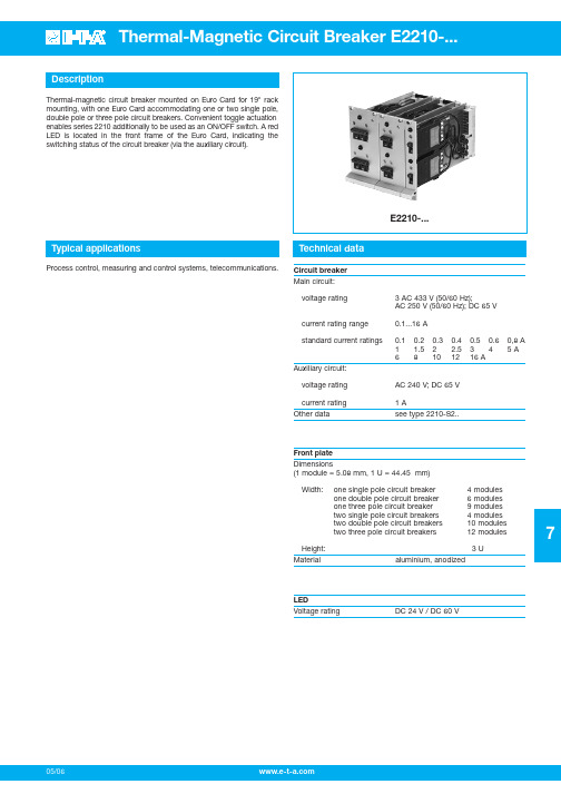
热磁电路断电器 E2210说明书
05/067DescriptionTypical applicationsTechnical dataThermal-magnetic circuit breaker mounted on Euro Card for 19" rack mounting, with one Euro Card accommodating one or two single pole,double pole or three pole circuit breakers. Convenient toggle actuation enables series 2210 additionally to be used as an ON/OFF switch. A red LED is located in the front frame of the Euro Card, indicating the switching status of the circuit breaker (via the auxiliary circuit).Process control, measuring and control systems, telecommunications.E2210-...Circuit breaker Main circuit:voltage rating 3 AC 433 V (50/60 Hz);AC 250 V (50/60 Hz); DC 65 V current rating range 0.1...16 A standard current ratings0.10.20.30.40.50.60,8 A1 1.52 2.5345 A681012 16 AAuxiliary circuit:voltage rating AC 240 V; DC 65 V current rating 1 AOther datasee type 2210-S2..Front plate Dimensions(1 module = 5.08 mm, 1 U = 44.45 mm)Width:one single pole circuit breaker 4 modules one double pole circuit breaker 6 modules one three pole circuit breaker 9 modules two single pole circuit breakers4 modules two double pole circuit breakers 10 modules two three pole circuit breakers12 modulesHeight: 3 U Material aluminium, anodizedLEDVoltage ratingDC 24 V / DC 60 V7One single pole circuit breakerOrdering informationType No.E2210Mounting style1 1 x single pole, central mounting (standard)2 1 x single pole, top mounting3 1 x single pole, bottom mounting4 1 x double pole, central mounting (standard)5 1 x three pole, central mounting (standard)6 2 x single pole, symmetrical mounting (standard)7 2 x double pole, symmetrical mounting (standard)8 2 x three pole, symmetrical mounting (standard)Front plate1aluminium (standard)2moulded (Intermas)LED1red, DC 24 V (standard)2red, DC 60 V3green, DC 24 V4green, DC 60 VCircuit breakerMountingS panel mountingActuator design2short toggleNumber of poles1 1 pole protected2 2 pole protected3 3 pole protected5 2 pole, protected on one pole onlyPanel mounting1with M3 threadTerminal design (main contacts) **P1blade terminals 6.3-0.8 (standard)Characteristic curve**01F1fast acting: therm. 1.01-1.4 x IN;magn. 2-4 x I N DC (DC only)02M1standard delay: therm. 1.01-1.4 x IN;magn. 6-12 x I N AC; 7.8-15.6 x I N DC03T1delayed:therm.1.01-1.4 x IN;magn.10-20 x I N AC04T2thermal only, 1.01-1.4 x IN05M3standard delay, low resistance:therm.1.4-1.8 x I N AC;magn.6-12 x I N AC; 7.8-15.6 x I N DCF2fast acting: therm. 1.1-1.4 x INmagn.3.5-6.5 x I N AC/DCXX different curves for multi pole versionsto order*Intermediate position**H without intermediate position (standard)Z with intermediate positionAuxiliary contacts**1with auxiliary contacts(only with 1x1 pole, 2x1 pole)5with auxiliary contact only in thelast unit of multipole versionsAuxiliary contact function**1 1 N/C, 1 N/O (standard)2 1 N/O (23/24)3 1 N/C (11/12)4 1 N/O contact, closed in theintermediate and ON position(-Z only)Auxiliary contact-terminal design1same as main terminals **Current ratings***0.1...16 AE2210 -6 1 1 - S 2 1 1 -02 -H 11 1 -0.1 AXX0.1/0,2 Aonly with 2x1 pole/2x2 pole/2x3 pole*) Clearly add the desired specifications.**) With mounting styles 6, 7 and 8: both circuit breakers must have thesame characteristics.***) It is possible to fit circuit breakers of mixed current ratings on theEuro Card.Two single pole circuit breakersThis is a metric design and millimeter dimensions take precedence (mm )inch05/06 05/067 419One double pole circuit breakerTwo double pole circuit breakersOne three pole circuit breakerTwo three pole circuit breakersThis is a metric design and millimeter dimensions take precedence (mm )inch05/067Sockets for Euro Cards Dimensions of sockets for Euro CardsDescriptionThe following sockets may be used with single pole circuit breakers:0Z041Z00000424/7 pole mixed socket to DIN 41612 - form M.Connection: 7 pole for 6.3x0.8 mm connectors and 24 pole midi-wire wrap posts (1 x 1 mm).0Z041Z00000724/7 pole mixed socket to DIN 41612 - form M.Connection: 7 pole for 6.3x0.8 mm connectors and 24 pole for 2.8x0.8 mm connectors.0Z041Z000005A 15 pole socket to DIN 41612, form H, for 6.3x0.8 mmconnectors is required in addition to the socket mentioned above, if two double pole or two three pole circuit breakers are fitted on one Euro Card.This is a metric design and millimeter dimensions take precedence (mm )inchAll dimensions without tolerances are for reference only. In the interest of improved design,performance and cost effectiveness the right to make changes in these specifications without notice is reserved.Product markings may not be exactly as the ordering codes.Errors and omissions excepted.。
gth22热载继电器说明书
gth22热载继电器说明书
产品参数:
品牌:LS产电
型号:GTH-22/3 7-10A
产品特性:热继电器
应用范围:安全
额定电流:36A
额定电压:220V
是否专供外贸:否
3C额定电压范围:36V-交流1000V
产品系列:3RH11
触点形式:4
防护特征:1
线圈电源:常规
线圈功率:36kw
最小包装数:1
种类:继电器
应用领域:电工电气
产品使用方式:
电动机在额定电流下工作时,不必热继电器维护。
即使过载20%运转,设计时也考虑了容许持续一段时间,不会立即焚毁。
但马达时有发生堵转或所拖动的机器出现故障,则会使马达过载而焚毁;而热继电器能在这段时间内很快切断电路,确保马达的正常运转。
目前,热继电器用以轻载起动的马达时,起动电流一般为额定电流的六倍左右,起动时间不会超过5秒,这时热继电器整定电流可调到相等马达的额定电流。
当马达过载20%时,热继电器通过直接串联联接在电路中的主副触头,在规定的时间内快速切断电源,保障马达过载。
热继电器能在5s内躲避六倍的起动电流而不致引起误动作。
热继电器在重载起动(或起动时间较长和拖动冲击性负载)的特别场合中,如气化炉的鼓风机、引风机,由于这些装置起动时间超过5s,热继电器整定电流应调到马达额定电流的1.1~1.15倍。
九一三四 EATON - 应急照明 CPS – 全球目录 2022说明书

9334 EATON - EMERGENCY LIGHTING CPS – Global Catalogue 2022 123InputRated voltage AC 1 ~ 220-240 V Rated frequency 50/60 Hz Max. rated current AC 5.5 A Rated voltage DC 19.2 -28.8 VBatteryVRLA, 2x6 cells in series, 20 °COutputRated voltage AC 220-240 V AC / 220 V DC konstant Total current4.7 A AC / 2.45 A DC Total power 1080 VA / 540 W Circuit power345 VA / 330 W Rated breaking capacity 1500 A @ 300 V DC Max. rated current 24 V auxiliary voltage6 WBatteryRated capacity AhK10, 1.8 V/Z, +20 °CDimensions of one battery L x W x H (mm)Number of batteries U B = 12 V piecesT otal weight of all batteries(kg)10 Y: 11 Ah 151 x 98 x 101max. 8 pieces4 pieces: 15.258 pieces: 30.50LP-STAR 4-12LP-STAR 4-24LP-STAR-4-36LP-STAR-4-48Circuits4444Max. battery size (C10; 1.8 V/Z, +20 °C) 2 x 12 V / 11 Ah4 x 12 V / 11 Ah6 x 12 V / 11 Ah8 x 12 V / 11 AhDimensions (W x H x D)260 x 550 x 260 mm 260 x 730 x 260 mmMax. ambient temperature For storage: -20 °C to + 40 °C, For operation*: -5 °C to + 35 °CSound pressure level at mains operation / emergency mode (converter operation)0 dB / 50 dBHousing colourRAL 7035Degree of protection / insulation class IP20 / IWeight (approx.) without battery17 kg21 kg* Maximum Design Lifetime at +20 °C: 10 yearsLP-STAR 4-24LP-STAR 4-48LP-STAR emergency lighting power supply in a compact designTechnical Data1 = 4 x M252 = 18 x M203 = 6 x M16LP-STAR9 EATON - EMERGENCY LIGHTING CPS – Global Catalogue 2022335Ordering detailsT ypeModelOrder No.Selection1LP-STAR 4-12LP-STAR-4-12, incl. control module, 1 charging unit, 4 circuits and battery packs 2 x 12 V / 12 Ah400713621202LP-STAR 4-24LP-STAR-4-24, incl. control module, 1 charging unit, 4 circuits and battery packs 4 x 12 V / 24 Ah400713622403LP-STAR 4-36LP-STAR-4-36, incl. control module, 1 charging unit, 4 circuits and battery packs 6 x 12 V / 36 Ah400713623604LP-STAR 4-48LP-STAR-4-48, incl. control module, 1 charging unit, 4 circuits and battery packs 8 x 12 V / 48 Ah40071362480Battery ordering detailsT ypeModelOrder No.Selection812 V/12 Ah spare part Battery block, period of use: 10 years Connector: Faston 4,3 mm40066071147 12V / 11AhBattery block, period of use: 10 years Connector: Faston 6,3mm40066071591Period of use specified for a max. battery temperature of +20 °CConstruction group ordering detailsT ypeModelOrder No.Selection5Webmodule LP-STARModule for DIN Rail Mounting, incl. connection line without patch cable RJ45, factory fitted400713614506Webmodule LP-STARModule for DIN Rail Mounting, incl. connection line without patch cable RJ45, for expansion400713614497CG-S Bus Interface*Attention: Installation must factory-provided happenedInerface* for connection on CGVision or for MasterSlave operation (Connection of more LP-STAR over the CG-S Bus)40071071178* A ttention:The installation of the CG-S Bus Interface must factory-provided happened. A expansion of themodule locally is only possibe with exchange of the full CSU module. MasterSlave and CGVision operation isn´t possible.Fuse ordering detailsT ypeModelOrder No.Selection9Final circuit fuses 2.5 AT / 250 V (packaging unit 10 pieces)40071361235 10Mains feed-in circuits6.3 AT / 250 V (packaging unit 10 pieces)40071361234Accessories ordering detailsT ypeModelOrder No.Selection11Clamping gland set, 28 pieces4 x M25, 18 x M20, 6 x M1640071361159LP-STAR 4-24LP-STAR emergency lighting power supply in a compact designTechnical DataLP-STAR。
- 1、下载文档前请自行甄别文档内容的完整性,平台不提供额外的编辑、内容补充、找答案等附加服务。
- 2、"仅部分预览"的文档,不可在线预览部分如存在完整性等问题,可反馈申请退款(可完整预览的文档不适用该条件!)。
- 3、如文档侵犯您的权益,请联系客服反馈,我们会尽快为您处理(人工客服工作时间:9:00-18:30)。
以上数据在25℃,海平面条件下测得。 线圈对极性很敏感。 仔细观察引出端上的标记。
©江苏中科国腾科技有限公司 版权所有 本公司保留所有解释权利。 页数 1/2 出版日期:2014-5-28
GT22L 外形图
型号选择说明
GT22L W F 12VDC
高压接头 W=螺栓连接 S=焊接式
安装
F=法兰式
P=螺栓式 12V=12Vd 115V=115Vdc
规格号 Specification No.
触点组合形式 Contact Configuration 试验电压 (直流或 50Hz 交流峰值) Test Voltage (DC or AC 50Hz Peak)kV DC or AC 50Hz 额定工作电压(峰值) AC2.5MHz Rated Operating AC16MHz Voltage(Peak) kV AC32MHz DC or AC 50Hz 额定承载电流(有效值) AC2.5MHz Rated Carrying AC16MHz Voltage(RMS) A AC32MHz 接触电阻 Contact Resistance (Ω) 断开的触点间 分 布 电 容 Contact Beteween Open Contacts Capacitance(pf) 触点与外壳间 Open Contacts to Ground 最大动作时间 Operate Time Max. (ms) 最大释放时间 Release Time Max.(ms) 温度范围 Range of Temp.(℃) 冲击级别 Shock, 11ms 1/2Sine(Peak g’s) 振动级别 Vibration ,Peak 10g’s( Hz) 机械寿命 Expected Mechanical Life(×106) 标称重量 Weight (g)
线圈电压
空白=26.5Vdc
按照上面的型号命名订购继电器。表示为保持型继电器的“L”标记和线圈电压未出现 在产品的型号标记中而表示在基座中线圈的标记中。
©江苏中科国腾科技有限公司
版权所有
本公司保留所有解释权利。
页数 2/2 出版日期:2014-5-28
磁保持高压继电器 Latching HV Relays
GT22L-15kV
www.
特点:GT22L 保持型线圈,低消耗功率,在线圈无电压时确保继电器保持
其最后的工作状态。耐磨损钨触点,可以热切换负载。真空介质有效灭弧。两种 可选安装方式,法兰安装或螺母安装。高压端焊接连接或用螺钉连接可以方便连 接。可以变化的线圈提供了多种选择,符合美军标 MIL-R-83725
GT22L
1C 17 Biblioteka 530 18 10 6 0.025 0.5 1 15 8 -55~+125 50 10~500 1 84(3)
线圈数据 Coil Parameter
标称电压 Rated Voltage DC(V) 最大吸合电压 Pull-in Voltage Max. DC(V) 释放电压 Dropout Voltage. Min.DC(V) 线圈电阻 Coil Resistance (Ω±10%) 12 8 0.5~5 -24(26.5) 16 1~10 -115 80 5-50 ---
