LM431 PDF
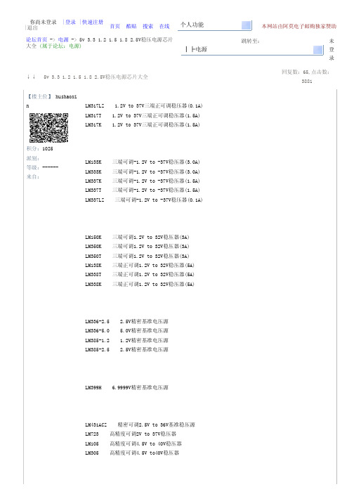
5v 3.3 1.2 1.5 1.8 2.5V稳压电源芯片大全
编辑 删除
【19楼】 ratrat 积分:164 派别: 等级:-----来自:
谢谢
2009-03-20,12:55:3 3
资料 邮件
回复
引用回复
↑↑
↓↓
编辑 删除
【20楼】 hailing
积分:261 派别: 等级:-----来自:
最好写下静态电流。对于低功耗的设备使用时很重要。我们用317是上面的电阻使用240的,这样就有1.2 5/240=5MA的电流了,对于要求低功耗的设备还是太大了。78系列也有几毫安的电流的。 补充一些:MAX6190 1.25V 5PPM基准 HT7533 3.3V100MA HT7133 3.3V 30MA 78L05 5V 100MA MCP1700 LDO,2.5V SPX3819 3V 1% SPX29032 ADJ 3A 1%
资料 邮件 回复 引用回复 ↑↑ ↓↓
【23楼】 wajlh
make
积分:2115 派别: 等级:-----来自:山东-莱阳
__________________________ 喜欢这里的气氛
2009-03-20,16:14:4 3
资料 邮件 回复 引用回复
↑↑
↓↓
【24楼】 jiongeyes 书册糕 积分:136 派别: 等级:-----来自:潮州,现在广州 单身
mark!
2009-03-23,08:10:3 0
资料 邮件
回复
引用回复
↑↑
↓↓
【31楼】 cgbabc 积分:1036 派别: 等级:-----来自:
MARK!
2009-03-23,11:38:2 3
资料 邮件
回复
引用回复
↑↑
lm431
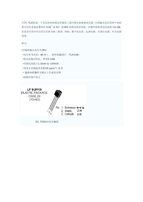
介绍: TL431是一个有良好的热稳定性能的三端可调分流基准电压源。
它的输出电压用两个电阻就可以任意地设置到从Vref(2.5V)到36V范围内的任何值。
该器件的典型动态阻抗为0.2Ω,在很多应用中可以用它代替齐纳二极管,例如,数字电压表,运放电路、可调压电源,开关电源等等。
特点:•可编程输出电压为36V•电压参考误差:±0.4%,典型值@25℃(TL431B)•低动态输出阻抗,典型0.22Ω•负载电流能力1.0mA to 100mA•等效全范围温度系数50 ppm/℃典型•温度补偿操作全额定工作温度范围•低输出噪声电压图1 TO92封装引脚图图2 8脚封装引脚功能图3 SOP-8 贴片封装引脚图图4 TL431符号及内部方框图图5 TL431内部电路图MAXIMUM RATINGS (Full operating ambient temperature range applies, unless otherwise noted.)最大额定值(环境温度范围适用,除非另有说明。
)Rating 参数Symbol 符号数值Unit 单位RECOMMENDED OPERATING CONDITIONS建议操作条件ELECTRICAL CHARACTERISTICS(TA=25℃, unless otherwise noted.)电气特性(25℃,除非另有说明。
)ELECTRICAL CHARACTERISTICS (TA = 25℃, unless otherwise noted.)电气特性(25℃,除非另有说明。
)2), ReferenceInput Current (Figure 2)参考输入电流IK = 10 mA, R1 = 10 k, R2 = ∞TA = 25℃Iref––1.84.0–1.84.–1.12.0μA TA = Tlowto Thigh(Note 1)– 6.5––5.2–– 4.0Reference Input Current Deviation OverTemperature Range (Figure 2, Note 1) IK = 10 mA, R1 = 10k, R2 = ∞参考输入电流偏差温度范围DIref–.82.5–.41.2–.82.5μAMinimum CathodeCurrent For Regulation 最小阴极电流调节VKA = Vref (Figure 1)Imin–.51.0–.51.–.51.0mAOff–State CathodeCurrent(Figure 3) 断态阴极电流VKA = 36V, Vref =0V Ioff–26100–261–23500nADynamic Impedance (Figure 1, Note 3) VKA =Vref, DIK = 1.0 mA to 100 mA f 3 1.0 kHz 动态阻抗|ZKA|–.220.5–.22.5–.140.3Ω图6 测试电路VKA = Vref 图7 测试电路VKA > Vref 图8 测试电路for Ioff曲线图:图9 阴极电流与阴极电压图10 阴极电流与阴极电压图11 参考输入电压与常温图12 参考输入电流与常温图13 变化的参考输入电压与阴极电压图14 断态阴极电流随环境温度图15 动态阻抗与频率图16 动态阻抗随环境温度图17 开环电压增益与频率图18 谱噪声密度图19 脉冲响应图20 稳定的边界条件应用法:图21测试电路曲线a 边界条件的稳定性图22曲线测试电路的B,C和D边界条件的稳定性图23并联稳压器电路图图24 大电流并联稳压器电路图25 控制三端固定稳压输出电路图26 串联稳压调节电路图27 过压保护电路图28 恒流源电路图29 恒定流入电流源电路图30 双向可控硅过压保护电路图31 电压监视器电路图32 单电源比较温度补偿电路图33 线性欧姆表电路图图34 简单的400毫瓦唱机放大器电路图35 高效率降压型开关转换器电路图图36 简体TL431器件模型图37 封装图图38 SOP-8 贴片封装图。
LM431 可调电压基准电路
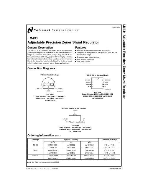
Temperature Range
0˚C to +70˚C −40˚C to +85˚C
0˚C to +70˚C −40˚C to +85˚C
0˚C to +70˚C −40˚C to +85˚C
Absolute Maximum Ratings (Note 2)
If Military/Aerospace specified devices are required, please contact the National Semiconductor Sales Office/ Distributors for availability and specifications.
DS010055-11
Note: The areas under the curves represent conditions that may cause the device to oscillate. For curves B, C, and D, R2 and V+ were adjusted to establish the initial VZ and IZ conditions with CL = 0. V+ and CL were then adjusted to determine the ranges of stability.
431BCM中文资料

LM431Adjustable Precision Zener Shunt RegulatorGeneral DescriptionThe LM431is a 3-terminal adjustable shunt regulator with guaranteed temperature stability over the entire temperature range of operation.It is now available in a chip sized pack-age (4-Bump micro SMD)using National’s micro SMD pack-age technology.The output voltage may be set at any level greater than 2.5V (V REF )up to 36V merely by selecting two external resistors that act as a voltage divided network.Due to the sharp turn-on characteristics this device is an excel-lent replacement for many zener diode applications.Featuresn Average temperature coefficient 50ppm/˚Cn Temperature compensated for operation over the full temperature rangen Programmable output voltage n Fast turn-on response n Low output noisen LM431in micro SMD packagen See AN-1112for micro SMD considerationsConnection DiagramsNote:*NC =Not internally connected.Must be electrically isolated from therest of the circuit for the microSMD package.TO-92:Plastic PackageDS010055-1Top ViewSO-8:8-Pin Surface MountDS010055-2Top viewSOT-23:3-Lead Small OutlineDS010055-28Top View 4-Bump micro SMDDS010055-54Top View(bump side down)March 2002LM431Adjustable Precision Zener Shunt Regulator©2002National Semiconductor Corporation Ordering InformationPackage Typical Accuracy Order Number/Package MarkingTemperature Range Transport MediaNSC Drawing0.5%1%2%TO-92LM431CCZ/LM431CCZ LM431BCZ/LM431BCZ LM431ACZ/LM431ACZ 0˚C to +70˚CRailsZ03ALM431CIZ/LM431CIZLM431BIZ/LM431BIZ LM431AIZ/LM431AIZ −40˚C to +85˚C SO-8LM431CCM/431CCM LM431BCM/431BCM LM431ACM/LM431ACM 0˚C to +70˚CRails and Tape &ReelM08A LM431CIM/431CIMLM431BIM/431BIM LM431AIM/LM431AIM −40˚C to +85˚C SOT-23LM431CCM3/N1B LM431BCM3/N1D LM431ACM3/N1F 0˚C to +70˚CRails and Tape &ReelMF03A LM431CIM3N1ALM431BIM3N1CLM431AIM3N1E−40˚C to +85˚C micro SMD––LM431AIBPLM431AIBPX(Note 1)−40˚C to +85˚C250Units Tape and Reel3k Units Tape and ReelBPA04AFBNote 1:The micro SMD package marking is a 1digit manufacturing Date Code onlymicro SMD Top View Marking ExampleDS010055-56L M 431 2Symbol and Functional DiagramsDC Test CircuitsDS010055-99DS010055-55DS010055-4FIGURE 1.Test Circuit for V Z =V REFDS010055-5Note:V Z =V REF (1+R1/R2)+I REF •R1FIGURE 2.Test Circuit for V Z >V REFDS010055-6FIGURE 3.Test Circuit for Off-State CurrentLM4313Absolute Maximum Ratings (Note 2)If Military/Aerospace specified devices are required,please contact the National Semiconductor Sales Office/Distributors for availability and specifications.Storage Temperature Range −65˚C to +150˚C Operating Temperature Range Industrial (LM431xI)−40˚C to +85˚C Commercial (LM431xC)0˚C to +70˚C Soldering InformationInfrared or Convection (20sec.)235˚CWave Soldering (10sec.)260˚C (lead temp.)Cathode Voltage37VContinuous Cathode Current−10mA to +150mAReference Voltage−0.5V Reference Input Current10mA Internal Power Dissipation (Notes 3,4)TO-92Package SO-8Package SOT-23Package 0.78W 0.81W 0.28W micro SMD Package0.30WOperating ConditionsMin Max Cathode Voltage V REF 37V Cathode Current1.0mA100mALM431Electrical CharacteristicsT A =25˚C unless otherwise specified Symbol ParameterConditionsMin Typ Max Units V REFReference VoltageV Z =V REF ,I I =10mA 2.4402.4952.550VLM431A (Figure 1)V Z =V REF ,I I =10mA 2.4702.4952.520VLM431B (Figure 1)V Z =V REF ,I I =10mA 2.4852.5002.510VLM431C (Figure 1)V DEVDeviation of Reference Input Voltage Over V Z =V REF ,I I =10mA,8.017mVTemperature (Note 5)T A =Full Range (Figure 1)Ratio of the Change in Reference Voltage I Z =10mAV Z from V REF to 10V −1.4−2.7mV/Vto the Change in Cathode Voltage(Figure 2)V Z from 10V to 36V−1.0−2.0I REF Reference Input CurrentR 1=10k Ω,R 2=∞, 2.04.0µA I I =10mA (Figure 2)∝I REFDeviation of Reference Input Current over R 1=10k Ω,R 2=∞,TemperatureI I =10mA,0.4 1.2µA T A =Full Range (Figure 2)I Z(MIN)Minimum Cathode Current for Regulation V Z =V REF (Figure 1)0.4 1.0mA I Z(OFF)Off-State CurrentV Z =36V,V REF =0V (Figure 3)0.31.0µA r ZDynamic Output Impedance (Note 6)V Z =V REF ,LM431A,0.75ΩFrequency =0Hz (Figure 1)V Z =V REF ,LM431B,LM431C 0.50ΩFrequency =0Hz (Figure 1)Note 2:Absolute Maximum Ratings indicate limits beyond which damage to the device may occur.Electrical specifications do not apply when operating the device beyond its rated operating conditions.Note 3:T J Max =150˚C.Note 4:Ratings apply to ambient temperature at 25˚C.Above this temperature,derate the TO-92at 6.2mW/˚C,the SO-8at 6.5mW/˚C,the SOT-23at 2.2mW/˚C and the micro SMD at 3mW/˚C.Note 5:Deviation of reference input voltage,V DEV ,is defined as the maximum variation of the reference input voltage over the full temperature range.L M 431 4LM431Electrical Characteristics(Continued)Where:T 2−T 1=full temperature change (0-70˚C).∝V REF can be positive or negative depending on whether the slope is positive or negative.Example:V DEV =8.0mV,V REF =2495mV,T 2−T 1=70˚C,slope is positive.Note 6:The dynamic output impedance,r Z ,is defined as:When the device is programmed with two external resistors,R1and R2,(see Figure 2),the dynamic output impedance of the overall circuit,r Z ,is defined as:Equivalent CircuitDS010055-7The average temperature coefficient of the reference input voltage,∝V REF ,is defined as:DS010055-3LM4315Typical Performance CharacteristicsInput Current vs V ZDS010055-29Thermal InformationDS010055-30Input Current vs V ZDS010055-31Dynamic Impedance vs FrequencyDS010055-9DS010055-10Stability Boundary ConditionsDS010055-11Note:The areas under the curves represent conditions that may cause the device to oscillate.For curves B,C,and D,R2and V +were adjusted to establish the initial V Z and I Z conditions with C L =0.V +and C L were then adjusted to determine the ranges of stability.Test Circuit for Curve A Above DS010055-12Test Circuit for Curves B,C and D AboveDS010055-13L M 431 6Typical ApplicationsShunt RegulatorDS010055-14Single Supply Comparator withTemperature Compensated ThresholdDS010055-15Series RegulatorDS010055-16Output Control of a ThreeTerminal Fixed RegulatorDS010055-17Higher Current Shunt RegulatorDS010055-18Crow BarDS010055-19LM4317Typical Applications(Continued)Over Voltage/Under VoltageProtection CircuitDS010055-20Voltage MonitorDS010055-21L M 431 8Typical Applications(Continued)Application Info1.0MountingTo ensure that the geometry of the micro SMD packagemaintains good physical contact with the printed circuitboard,pin A1(NC)must be soldered to the pcb.Please seeAN-1112for more detailed information regarding boardmounting techniques for the micro SMD package.2.0LM431micro SMD Light SensitivityWhen the LM431micro SMD package is exposed to brightsunlight,normal office fluorescent light,and other LED’s andlasers,it operates within the guaranteed limits specified inthe electrical characteristics table.Delay TimerDS010055-22Current Limiter or Current SourceDS010055-23Constant Current SinkDS010055-24LM4319Physical Dimensionsinches (millimeters)unless otherwise notedNS Package Number M08ASOT-23Molded Small Outline Transistor Package (M3)NS Package Number MF03AL M 431 10LM431 Physical Dimensions inches(millimeters)unless otherwise noted(Continued)11Physical Dimensions inches(millimeters)unless otherwise noted(Continued)LIFE SUPPORT POLICYNATIONAL’S PRODUCTS ARE NOT AUTHORIZED FOR USE AS CRITICAL COMPONENTS IN LIFE SUPPORT DEVICES OR SYSTEMS WITHOUT THE EXPRESS WRITTEN APPROVAL OF THE PRESIDENT AND GENERAL COUNSEL OF NATIONAL SEMICONDUCTOR CORPORATION.As used herein:1.Life support devices or systems are devices orsystems which,(a)are intended for surgical implantinto the body,or(b)support or sustain life,andwhose failure to perform when properly used inaccordance with instructions for use provided in thelabeling,can be reasonably expected to result in asignificant injury to the user.2.A critical component is any component of a lifesupport device or system whose failure to performcan be reasonably expected to cause the failure ofthe life support device or system,or to affect itssafety or effectiveness.National SemiconductorCorporationAmericasEmail:support@National SemiconductorEuropeFax:+49(0)180-5308586Email:europe.support@Deutsch Tel:+49(0)6995086208English Tel:+44(0)8702402171Français Tel:+33(0)141918790National SemiconductorAsia Pacific CustomerResponse GroupTel:65-2544466Fax:65-2504466Email:ap.support@National SemiconductorJapan Ltd.Tel:81-3-5639-7560Fax:81-3-5639-7507 NOTES:UNLESS OTHERWISE SPECIFIED1.EPOXY COATING2.63Sn/37Pb EUTECTIC BUMP3.RECOMMEND NON-SOLDER MASK DEFINED LANDING PAD.4.PIN A1IS ESTABLISHED BY LOWER LEFT CORNER WITH RESPECT TO TEXT ORIENTATION.REMAINING PINS ARENUMBERED.5.XXX IN DRAWING NUMBER REPRESENTS PACKAGE SIZE VARIATION WHERE X1IS PACKAGE WIDTH,X2ISPACKAGE LENGTH AND X3IS PACKAGE HEIGHT.6.REFERENCE JEDEC REGISTRATION MO-211,VARIATION BA.4-Bump micro SMDX1=0.777X2=0.904X3=0.850NS Package Number BPA04AFBLM431AdjustablePrecisionZenerShuntRegulatorNational does not assume any responsibility for use of any circuitry described,no circuit patent licenses are implied and National reserves the right at any time without notice to change said circuitry and specifications.。
常用稳压器大全
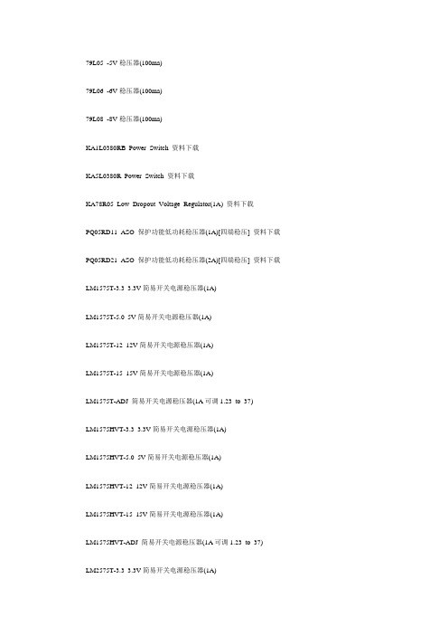
79L05 -5V稳压器(100ma)79L06 -6V稳压器(100ma)79L08 -8V稳压器(100ma)KA1L0380RB Power Switch 资料下载KA5L0380R Power Switch 资料下载KA78R05 Low Dropout Voltage Regulator(1A) 资料下载PQ05RD11 ASO 保护功能低功耗稳压器(1A)[四端稳压] 资料下载PQ05RD21 ASO 保护功能低功耗稳压器(2A)[四端稳压] 资料下载LM1575T-3.3 3.3V简易开关电源稳压器(1A)LM1575T-5.0 5V简易开关电源稳压器(1A)LM1575T-12 12V简易开关电源稳压器(1A)LM1575T-15 15V简易开关电源稳压器(1A)LM1575T-ADJ 简易开关电源稳压器(1A可调1.23 to 37)LM1575HVT-3.3 3.3V简易开关电源稳压器(1A)LM1575HVT-5.0 5V简易开关电源稳压器(1A)LM1575HVT-12 12V简易开关电源稳压器(1A)LM1575HVT-15 15V简易开关电源稳压器(1A)LM1575HVT-ADJ 简易开关电源稳压器(1A可调1.23 to 37)LM2575T-3.3 3.3V简易开关电源稳压器(1A)LM2575T-5.0 5V简易开关电源稳压器(1A)LM2575T-12 12V简易开关电源稳压器(1A)LM2575T-15 15V简易开关电源稳压器(1A)LM2575T-ADJ 简易开关电源稳压器(1A可调1.23 to 37)LM2575HVT-3.3 3.3V简易开关电源稳压器(1A)LM2575HVT-5.0 5V简易开关电源稳压器(1A)LM2575HVT-12 12V简易开关电源稳压器(1A)LM2575HVT-15 15V简易开关电源稳压器(1A)LM2575HVT-ADJ 简易开关电源稳压器(1A可调1.23 to 37) LM2576T-3.3 3.3V简易开关电源稳压器(3A)LM2576T-5.0 5.0V简易开关电源稳压器(3A)LM2576T-12 12V简易开关电源稳压器(3A)LM2576T-15 15V简易开关电源稳压器(3A)LM2576T-ADJ 简易开关电源稳压器(3A可调1.23V to 37V) LM2576HVT-3.3 3.3V简易开关电源稳压器(3A)LM2576HVT-5.0 5.0V简易开关电源稳压器(3A)LM2576HVT-12 12V简易开关电源稳压器(3A)LM2576HVT-15 15V简易开关电源稳压器(3A)LM2576HVT-ADJ 简易开关电源稳压器(3A可调1.23V to 37V)LM2930T-5.0 5.0V低压差稳压器LM2930T-8.0 8.0V低压差稳压器LM2931AZ-5.0 5.0V低压差稳压器(TO-92)LM2931T-5.0 5.0V低压差稳压器LM2931CT 3V to 29V低压差稳压器(TO-220,5PIN) LM2940CT-5.0 5.0V低压差稳压器LM2940CT-8.0 8.0V低压差稳压器LM2940CT-9.0 9.0V低压差稳压器LM2940CT-10 10V低压差稳压器LM2940CT-12 12V低压差稳压器型号(规格) 器件简介相同型号LM2940CT-15 15V低压差稳压器LM123K(NS) 5V稳压器(3A)LM323K(NS) 5V稳压器(3A)LM117K(NS) 1.2V to 37V三端正可调稳压器(1.5A) LM317LZ(NS) 1.2V to 37V三端正可调稳压器(0.1A) LM317T(NS) 1.2V to 37V三端正可调稳压器(1.5A) LM317K(NS) 1.2V to 37V三端正可调稳压器(1.5A) LM133K(NS) 三端可调-1.2V to -37V稳压器(3.0A)LM333K(NS) 三端可调-1.2V to -37V稳压器(3.0A)LM337K(NS) 三端可调-1.2V to -37V稳压器(1.5A)LM337T(NS) 三端可调-1.2V to -37V稳压器(1.5A)LM337LZ(NS) 三端可调-1.2V to -37V稳压器(0.1A)LM150K(NS) 三端可调1.2V to 32V稳压器(3A)LM350K(NS) 三端可调1.2V to 32V稳压器(3A)LM350T(NS) 三端可调1.2V to 32V稳压器(3A)LM138K(NS) 三端正可调1.2V to 32V稳压器(5A)LM338T(NS) 三端正可调1.2V to 32V稳压器(5A)LM338K(NS) 三端正可调1.2V to 32V稳压器(5A)LM336Z-2.5(NS) 2.5V精密基准电压源KA336Z-2.5(FSC)LM336Z-5.0(NS) 5.0V精密基准电压源KA336Z-5.0(FSC)LM385Z-1.2(NS) 1.2V精密基准电压源LM385Z-2.5(NS) 2.5V精密基准电压源LM399H 6.9999V精密基准电压源LM431ACZ(NS) 精密可调2.5V to 36V基准稳压源LM431ACZ(FSC) LM723 高精度可调2V to 37V稳压器LM723CN(ST)LM105 高精度可调4.5V to 40V稳压器LM305 高精度可调4.5V to 40V稳压器MC1403 2.5V基准电压源MC34063 充电控制器SG3524 脉宽调制开关电源控制器TL431(TI) 精密可调2.5V to 36V基准稳压源LM431ACZ(NSC)TL494 脉宽调制开关电源控制器TL497 频率调制开关电源控制器TL7705(TI) 电池供电/欠压控制器HT1015 1.5V Voltage Regulator [DATA](PDF-608K)HT7130=HT1030 3.0V High Voltage Regulator [DATA](PDF-199K)HT7133=HT1033 3.3V High Voltage Regulator [DATA](PDF-199K)HT7136=HT1036 3.6V High Voltage Regulator [DATA](PDF-199K)HT7144=HT1044 4.4V High Voltage Regulator [DATA](PDF-199K)HT7150=HT1050 5.0V High Voltage Regulator [DATA](PDF-199K)HT7530 3.0V 100mA High input Voltage Regulator [DATA](PDF-155K) HT7533 3.3V 100mA High input Voltage Regulator [DATA](PDF-155K) HT7536 3.6V 100mA High input Voltage Regulator [DATA](PDF-155K) HT7544 4.4V 100mA High input Voltage Regulator [DATA](PDF-155K) HT7550 5.0V 100mA High input Voltage Regulator [DATA](PDF-155K) HT7022 2.2V Voltage Detector [DATA](PDF-495K)HT7024 2.4V Voltage Detector [DATA](PDF-495K) HT7027 2.7V Voltage Detector [DATA](PDF-495K) HT7033 3.3V Voltage Detector [DATA](PDF-495K) HT7039 3.9V Voltage Detector [DATA](PDF-495K) HT7044 4.4V Voltage Detector [DATA](PDF-495K) HT7050 5.0V Voltage Detector [DATA](PDF-495K) HT7070 7.0V Voltage Detector [DATA](PDF-495K) LM7805 5V稳压器(1A) L7805,LM340T5LM7806 6V稳压器(1A) L7806LM7808 8V稳压器(1A) L7808LM7809 9V稳压议(1A) L7809LM7812 12V稳压器(1A) L7812,LM340T12LM7815 15V稳压器(1A) L7815,LM340T15LM7818 18V稳压器(1A) L7815LM7824 24V稳压器(1A) L7824LM7905 -5V稳压器(1A) L7905LM7906 -6V稳压器(1A) L7906,KA7906LM7908 -8V稳压器(1A) L7908LM7909 -9V稳压器(1A) L7909LM7912 -12V稳压器(1A) L7912 LM7915 -15V稳压器(1A) L7915 LM7918 -18V稳压器(1A) L7918 LM7924 -24V稳压器(1A) L7924 78L05 5V稳压器(100ma)78L06 6V稳压器(100ma)78L08 8V稳压器(100ma)78L09 9V稳压器(100ma)78L12 12V稳压器(100ma)78L15 15V稳压器(100ma)78L18 18V稳压器(100ma)78L24 24V稳压器(100ma)。
常用电子芯片资料
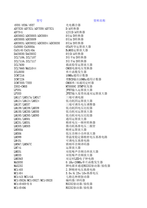
低功耗JFET输入运算放大器 低噪声JFET输入运算放大器 JFET 宽带高速运算放大器 脉宽调制PWM 精密开关模式脉宽调制控制 光电耦合器 TOPSwitch 三端PWM开关电源电路 TOPSwitch 三端PWM开关电源电路 TOPSwitch 三端PWM开关电源电路 TOPSwitch-Ⅱ 三端PWM开关电源电路 TOPSwitch-FX 五端柔韧设计开关电源电路 TOPSwitch 三端PWM DC-DC 开关电源 1.5A/50V 4路达林顿驱动电路 500mA/50V 8路达林顿驱动电路
NE5534/NE5534A/SE5534/SE5534A 低噪声运算放大器 NE555/NE555Y/SA555/SE555 单时基电路
NE570/NE571/SA571 音频压缩扩展器
PC817/PC827/PC837/PC847 高效光电耦合器 Remote Control Encoder PT2262 无线遥控发射编码器芯片 Remote Control Decoder PT2272 无线遥控接收解码器芯片
LM124/LM124/LM324/LM2902 低功耗四运算放大器 LM139/LM239/LM339/LM2901/LM3302 低功耗四电压比较器 LM158/LM258/LM358/LM2904 低功耗双运算放大器 LM193/LM293/LM393/LM2903 低功耗双电压比较器 LM231A/LM231/LM331A/LM331 精密电压—频率转换器
MC7805(5.0V)、LM340-5(5.0V)、MC7806(6.0V)、MC7808 (8.0V)、MC7809(9.0V) MC78L05(5.0V)、MC78L08(8.0V)、MC78L09(9.0V)、MC78L12 (12V)、MC78L15 MC78M05(5.0V)、MC78M06(6.0V)、MC78M08(8.0V)、MC78M09 (9.0V)、MC78M12 MC78T05(5.0V)、MC78T08(8.0V)、MC78T12(12V)、MC78T15 (15V) MC7905(5.0V)、MC7905.2(5.2V)、MC7906(6.0V)、MC7908 (8.0V)、MC7912(12V) MC79L05(5.0V)、MC79L12(12V)、MC79L15(15V)、MC79L18 (18V)、MC79L24(24V) MC79M05(5.0V)、MC79M08(8.0V)、MC79M12(12V)、MC79M15 (15V) Microchip PIC系列单片机与数字温度计的RS232通讯应用,内有典型应用电路图、源程序 常用于LM8361、LM8362、LM8365等电子钟电路将3.579545MHz晶体振荡分频到60Hz 250V OPTOCOUPLERS/OPTOISOLATORS 400V OPTOCOUPLERS/OPTOISOLATORS 800V 6-Pin DIP Zero-Cross Optoisolators Triac Driver Output PHOTODARLINGTON OPTOCOUPLER PHOTODARLINGTON OPTOCOUPLER MT8870C/MT8870C-1 Integrated DTMF Receiver DTMF双音频接收器 Integrated DTMF Transceiver with Intel Micro Interface
LM431相关中文资料
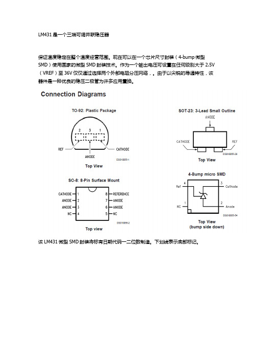
LM431是一个三端可调并联稳压器
保证温度稳定在整个温度经营范围。现在可以在一个芯片尺寸封装(4-bump微型SMD)使用国家的微型SMD封装技术。作为一个输出电压可设置在任何级别大于2.5V(VREF)至36V仅仅通过选择两个外部电阻分压网络,。由于以尖锐的导通特性,该器件是一种优良的稳压二极管为许多应用置换。
该பைடு நூலகம்M431微型SMD封装将标有日期代码一二位数制造。下划线表示底部标记。
LM431AIM3中文资料

LM431Adjustable Precision Zener Shunt RegulatorGeneral DescriptionThe LM431is a 3-terminal adjustable shunt regulator with guaranteed temperature stability over the entire temperature range of operation.It is now available in a chip sized pack-age (4-Bump micro SMD)using National’s micro SMD pack-age technology.The output voltage may be set at any level greater than 2.5V (V REF )up to 36V merely by selecting two external resistors that act as a voltage divided network.Due to the sharp turn-on characteristics this device is an excel-lent replacement for many zener diode applications.Featuresn Average temperature coefficient 50ppm/˚Cn Temperature compensated for operation over the full temperature rangen Programmable output voltage n Fast turn-on response n Low output noisen LM431in micro SMD packagen See AN-1112for micro SMD considerationsConnection DiagramsNote:*NC =Not internally connected.Must be electrically isolated from therest of the circuit for the microSMD package.TO-92:Plastic PackageDS010055-1Top ViewSO-8:8-Pin Surface MountDS010055-2Top viewSOT-23:3-Lead Small OutlineDS010055-28Top View 4-Bump micro SMDDS010055-54Top View(bump side down)March 2002LM431Adjustable Precision Zener Shunt Regulator©2002National Semiconductor Corporation Ordering InformationPackage Typical Accuracy Order Number/Package MarkingTemperature Range Transport MediaNSC Drawing0.5%1%2%TO-92LM431CCZ/LM431CCZ LM431BCZ/LM431BCZ LM431ACZ/LM431ACZ 0˚C to +70˚CRailsZ03ALM431CIZ/LM431CIZLM431BIZ/LM431BIZ LM431AIZ/LM431AIZ −40˚C to +85˚C SO-8LM431CCM/431CCM LM431BCM/431BCM LM431ACM/LM431ACM 0˚C to +70˚CRails and Tape &ReelM08A LM431CIM/431CIMLM431BIM/431BIM LM431AIM/LM431AIM −40˚C to +85˚C SOT-23LM431CCM3/N1B LM431BCM3/N1D LM431ACM3/N1F 0˚C to +70˚CRails and Tape &ReelMF03A LM431CIM3N1ALM431BIM3N1CLM431AIM3N1E−40˚C to +85˚C micro SMD––LM431AIBPLM431AIBPX(Note 1)−40˚C to +85˚C250Units Tape and Reel3k Units Tape and ReelBPA04AFBNote 1:The micro SMD package marking is a 1digit manufacturing Date Code onlymicro SMD Top View Marking ExampleDS010055-56L M 431 2Symbol and Functional DiagramsDC Test CircuitsDS010055-99DS010055-55DS010055-4FIGURE 1.Test Circuit for V Z =V REFDS010055-5Note:V Z =V REF (1+R1/R2)+I REF •R1FIGURE 2.Test Circuit for V Z >V REFDS010055-6FIGURE 3.Test Circuit for Off-State CurrentLM4313Absolute Maximum Ratings (Note 2)If Military/Aerospace specified devices are required,please contact the National Semiconductor Sales Office/Distributors for availability and specifications.Storage Temperature Range −65˚C to +150˚C Operating Temperature Range Industrial (LM431xI)−40˚C to +85˚C Commercial (LM431xC)0˚C to +70˚C Soldering InformationInfrared or Convection (20sec.)235˚CWave Soldering (10sec.)260˚C (lead temp.)Cathode Voltage37VContinuous Cathode Current−10mA to +150mAReference Voltage−0.5V Reference Input Current10mA Internal Power Dissipation (Notes 3,4)TO-92Package SO-8Package SOT-23Package 0.78W 0.81W 0.28W micro SMD Package0.30WOperating ConditionsMin Max Cathode Voltage V REF 37V Cathode Current1.0mA100mALM431Electrical CharacteristicsT A =25˚C unless otherwise specified Symbol ParameterConditionsMin Typ Max Units V REFReference VoltageV Z =V REF ,I I =10mA 2.4402.4952.550VLM431A (Figure 1)V Z =V REF ,I I =10mA 2.4702.4952.520VLM431B (Figure 1)V Z =V REF ,I I =10mA 2.4852.5002.510VLM431C (Figure 1)V DEVDeviation of Reference Input Voltage Over V Z =V REF ,I I =10mA,8.017mVTemperature (Note 5)T A =Full Range (Figure 1)Ratio of the Change in Reference Voltage I Z =10mAV Z from V REF to 10V −1.4−2.7mV/Vto the Change in Cathode Voltage(Figure 2)V Z from 10V to 36V−1.0−2.0I REF Reference Input CurrentR 1=10k Ω,R 2=∞, 2.04.0µA I I =10mA (Figure 2)∝I REFDeviation of Reference Input Current over R 1=10k Ω,R 2=∞,TemperatureI I =10mA,0.4 1.2µA T A =Full Range (Figure 2)I Z(MIN)Minimum Cathode Current for Regulation V Z =V REF (Figure 1)0.4 1.0mA I Z(OFF)Off-State CurrentV Z =36V,V REF =0V (Figure 3)0.31.0µA r ZDynamic Output Impedance (Note 6)V Z =V REF ,LM431A,0.75ΩFrequency =0Hz (Figure 1)V Z =V REF ,LM431B,LM431C 0.50ΩFrequency =0Hz (Figure 1)Note 2:Absolute Maximum Ratings indicate limits beyond which damage to the device may occur.Electrical specifications do not apply when operating the device beyond its rated operating conditions.Note 3:T J Max =150˚C.Note 4:Ratings apply to ambient temperature at 25˚C.Above this temperature,derate the TO-92at 6.2mW/˚C,the SO-8at 6.5mW/˚C,the SOT-23at 2.2mW/˚C and the micro SMD at 3mW/˚C.Note 5:Deviation of reference input voltage,V DEV ,is defined as the maximum variation of the reference input voltage over the full temperature range.L M 431 4LM431Electrical Characteristics(Continued)Where:T 2−T 1=full temperature change (0-70˚C).∝V REF can be positive or negative depending on whether the slope is positive or negative.Example:V DEV =8.0mV,V REF =2495mV,T 2−T 1=70˚C,slope is positive.Note 6:The dynamic output impedance,r Z ,is defined as:When the device is programmed with two external resistors,R1and R2,(see Figure 2),the dynamic output impedance of the overall circuit,r Z ,is defined as:Equivalent CircuitDS010055-7The average temperature coefficient of the reference input voltage,∝V REF ,is defined as:DS010055-3LM4315Typical Performance CharacteristicsInput Current vs V ZDS010055-29Thermal InformationDS010055-30Input Current vs V ZDS010055-31Dynamic Impedance vs FrequencyDS010055-9DS010055-10Stability Boundary ConditionsDS010055-11Note:The areas under the curves represent conditions that may cause the device to oscillate.For curves B,C,and D,R2and V +were adjusted to establish the initial V Z and I Z conditions with C L =0.V +and C L were then adjusted to determine the ranges of stability.Test Circuit for Curve A Above DS010055-12Test Circuit for Curves B,C and D AboveDS010055-13L M 431 6Typical ApplicationsShunt RegulatorDS010055-14Single Supply Comparator withTemperature Compensated ThresholdDS010055-15Series RegulatorDS010055-16Output Control of a ThreeTerminal Fixed RegulatorDS010055-17Higher Current Shunt RegulatorDS010055-18Crow BarDS010055-19LM4317Typical Applications(Continued)Over Voltage/Under VoltageProtection CircuitDS010055-20Voltage MonitorDS010055-21L M 431 8Typical Applications(Continued)Application Info1.0MountingTo ensure that the geometry of the micro SMD packagemaintains good physical contact with the printed circuitboard,pin A1(NC)must be soldered to the pcb.Please seeAN-1112for more detailed information regarding boardmounting techniques for the micro SMD package.2.0LM431micro SMD Light SensitivityWhen the LM431micro SMD package is exposed to brightsunlight,normal office fluorescent light,and other LED’s andlasers,it operates within the guaranteed limits specified inthe electrical characteristics table.Delay TimerDS010055-22Current Limiter or Current SourceDS010055-23Constant Current SinkDS010055-24LM4319Physical Dimensionsinches (millimeters)unless otherwise notedNS Package Number M08ASOT-23Molded Small Outline Transistor Package (M3)NS Package Number MF03AL M 431 10LM431 Physical Dimensions inches(millimeters)unless otherwise noted(Continued)11Physical Dimensions inches(millimeters)unless otherwise noted(Continued)LIFE SUPPORT POLICYNATIONAL’S PRODUCTS ARE NOT AUTHORIZED FOR USE AS CRITICAL COMPONENTS IN LIFE SUPPORT DEVICES OR SYSTEMS WITHOUT THE EXPRESS WRITTEN APPROVAL OF THE PRESIDENT AND GENERAL COUNSEL OF NATIONAL SEMICONDUCTOR CORPORATION.As used herein:1.Life support devices or systems are devices orsystems which,(a)are intended for surgical implantinto the body,or(b)support or sustain life,andwhose failure to perform when properly used inaccordance with instructions for use provided in thelabeling,can be reasonably expected to result in asignificant injury to the user.2.A critical component is any component of a lifesupport device or system whose failure to performcan be reasonably expected to cause the failure ofthe life support device or system,or to affect itssafety or effectiveness.National SemiconductorCorporationAmericasEmail:support@National SemiconductorEuropeFax:+49(0)180-5308586Email:europe.support@Deutsch Tel:+49(0)6995086208English Tel:+44(0)8702402171Français Tel:+33(0)141918790National SemiconductorAsia Pacific CustomerResponse GroupTel:65-2544466Fax:65-2504466Email:ap.support@National SemiconductorJapan Ltd.Tel:81-3-5639-7560Fax:81-3-5639-7507 NOTES:UNLESS OTHERWISE SPECIFIED1.EPOXY COATING2.63Sn/37Pb EUTECTIC BUMP3.RECOMMEND NON-SOLDER MASK DEFINED LANDING PAD.4.PIN A1IS ESTABLISHED BY LOWER LEFT CORNER WITH RESPECT TO TEXT ORIENTATION.REMAINING PINS ARENUMBERED.5.XXX IN DRAWING NUMBER REPRESENTS PACKAGE SIZE VARIATION WHERE X1IS PACKAGE WIDTH,X2ISPACKAGE LENGTH AND X3IS PACKAGE HEIGHT.6.REFERENCE JEDEC REGISTRATION MO-211,VARIATION BA.4-Bump micro SMDX1=0.777X2=0.904X3=0.850NS Package Number BPA04AFBLM431AdjustablePrecisionZenerShuntRegulatorNational does not assume any responsibility for use of any circuitry described,no circuit patent licenses are implied and National reserves the right at any time without notice to change said circuitry and specifications.。
LM431中文手册
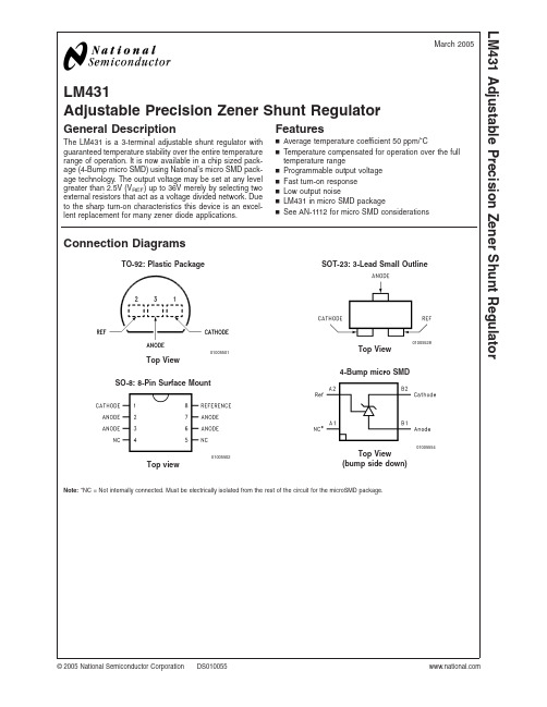
LM431Adjustable Precision Zener Shunt RegulatorGeneral DescriptionThe LM431is a 3-terminal adjustable shunt regulator with guaranteed temperature stability over the entire temperature range of operation.It is now available in a chip sized pack-age (4-Bump micro SMD)using National’s micro SMD pack-age technology.The output voltage may be set at any level greater than 2.5V (V REF )up to 36V merely by selecting two external resistors that act as a voltage divided network.Due to the sharp turn-on characteristics this device is an excel-lent replacement for many zener diode applications.Featuresn Average temperature coefficient 50ppm/˚Cn Temperature compensated for operation over the full temperature rangen Programmable output voltage n Fast turn-on response n Low output noisen LM431in micro SMD packagen See AN-1112for micro SMD considerationsConnection DiagramsTO-92:Plastic Package01005501Top ViewSO-8:8-Pin Surface Mount01005502Top viewSOT-23:3-Lead Small Outline01005528Top View 4-Bump micro SMD01005554Top View(bump side down)Note:*NC =Not internally connected.Must be electrically isolated from the rest of the circuit for the microSMD package.March 2005LM431Adjustable Precision Zener Shunt Regulator©2005National Semiconductor Corporation Ordering InformationPackageTypical Accuracy Order Number/PackageMarking TemperatureRangeTransport MediaNSC Drawing0.5%1%2%TO-92LM431CCZ/LM431CCZ LM431BCZ/LM431BCZ LM431ACZ/LM431ACZ 0˚C to +70˚CRailsZ03ALM431CIZ/LM431CIZLM431BIZ/LM431BIZ LM431AIZ/LM431AIZ −40˚C to +85˚CSO-8LM431CCM/431CCM LM431BCM/431BCMLM431ACM/LM431ACM0˚C to +70˚CRailsM08ALM431CCMX/431CCM LM431BCMX/431BCM LM431ACMX/LM431ACM Tape &ReelLM431CIM/431CIM LM431BIM/431BIM LM431AIM/LM431AIM −40˚C to +85˚CRailsLM431CIMX/431CIMLM431BIMX/431BIMLM431AIMX/LM431AIMTape &ReelSOT-23LM431CCM3/N1BLM431BCM3/N1D LM431ACM3/N1F0˚C to +70˚CRailsMF03ALM431CCM3X/N1B LM431BCM3X/N1D LM431ACM3X/N1F Tape &ReelLM431CIM3N1ALM431BIM3N1CLM431AIM3N1E−40˚C to +85˚CRailsLM431CIM3XN1ALM431BIM3X N1C LM431AIM3XN1ETape &Reel micro SMD––LM431AIBPLM431AIBPX (Note 1)−40˚C to +85˚C 250Units Tape andReel3k Units Tape andReelBPA04AFBNote 1:The micro SMD package marking is a 1digit manufacturing Date Code onlymicro SMD Top View Marking Example01005556L M 431 2Symbol and Functional Diagrams0100559901005555DC Test Circuits01005506Test Circuit for Off-State Current01005504FIGURE 1.Test Circuit for V Z =V REF01005505Note:V Z =V REF (1+R1/R2)+I REF •R1FIGURE 2.Test Circuit for V Z >V REFLM4313Absolute Maximum Ratings (Note 2)If Military/Aerospace specified devices are required,please contact the National Semiconductor Sales Office/Distributors for availability and specifications.Storage Temperature Range −65˚C to +150˚COperating Temperature Range Industrial (LM431xI)−40˚C to +85˚C Commercial (LM431xC)0˚C to +70˚C Soldering InformationInfrared or Convection (20sec.)235˚CWave Soldering (10sec.)260˚C (lead temp.)Cathode Voltage37VContinuous Cathode Current−10mA to +150mA Reference Voltage −0.5V Reference Input Current10mAInternal Power Dissipation (Notes 3,4)TO-92Package SO-8Package SOT-23Package 0.78W 0.81W 0.28W micro SMD Package0.30WOperating ConditionsMinMax Cathode Voltage V REF 37V Cathode Current1.0mA100mALM431Electrical CharacteristicsT A =25˚C unless otherwise specified Symbol ParameterConditionsMin Typ Max Units V REFReference VoltageV Z =V REF ,I I =10mA 2.4402.4952.550VLM431A (Figure 1)V Z =V REF ,I I =10mA 2.4702.4952.520VLM431B (Figure 1)V Z =V REF ,I I =10mA 2.4852.5002.510VLM431C (Figure 1)V DEVDeviation of Reference Input Voltage Over V Z =V REF ,I I =10mA,8.017mVTemperature (Note 5)T A =Full Range (Figure 1)Ratio of the Change in Reference Voltage I Z =10mA V Z from V REF to 10V −1.4−2.7mV/Vto the Change in Cathode Voltage(Figure 2)V Z from 10V to 36V−1.0−2.0I REF Reference Input CurrentR 1=10k Ω,R 2=∞, 2.04.0µA I I =10mA (Figure 2)∝I REFDeviation of Reference Input Current over R 1=10k Ω,R 2=∞,TemperatureI I =10mA,0.4 1.2µA T A =Full Range (Figure 2)I Z(MIN)Minimum Cathode Current for Regulation V Z =V REF (Figure 1)0.4 1.0mA I Z(OFF)Off-State CurrentV Z =36V,V REF =0V (Figure *NO TARGET FOR fi*)0.31.0µA r ZDynamic Output Impedance (Note 6)V Z =V REF ,LM431A,0.75ΩFrequency =0Hz (Figure 1)V Z =V REF ,LM431B,LM431C 0.50ΩFrequency =0Hz (Figure 1)Note 2:Absolute Maximum Ratings indicate limits beyond which damage to the device may occur.Electrical specifications do not apply when operating the device beyond its rated operating conditions.Note 3:T J Max =150˚C.Note 4:Ratings apply to ambient temperature at 25˚C.Above this temperature,derate the TO-92at 6.2mW/˚C,the SO-8at 6.5mW/˚C,the SOT-23at 2.2mW/˚C and the micro SMD at 3mW/˚C.Note 5:Deviation of reference input voltage,V DEV ,is defined as the maximum variation of the reference input voltage over the full temperature range.L M 431 4LM431Electrical Characteristics(Continued)01005507The average temperature coefficient of the reference input voltage,∝V REF ,is defined as:Where:T 2−T 1=full temperature change (0-70˚C).∝V REF can be positive or negative depending on whether the slope is positive or negative.Example:V DEV =8.0mV,V REF =2495mV,T 2−T 1=70˚C,slope is positive.Note 6:The dynamic output impedance,r Z ,is defined as:When the device is programmed with two external resistors,R1and R2,(see Figure 2),the dynamic output impedance of the overall circuit,r Z ,is defined as:LM4315Equivalent Circuit01005503Typical Performance CharacteristicsInput Current vs V ZThermal Information0100552901005530Input Current vs V ZDynamic Impedance vs Frequency0100553101005509L M 431 6Typical Performance Characteristics(Continued)Stability Boundary Conditions01005511Note:The areas under the curves represent conditions that may cause thedevice to oscillate.For curves B,C,and D,R2and V+were adjusted toestablish the initial V Z and I Z conditions with C L=0.V+and C L were thenadjusted to determine the ranges of stability.01005510Test Circuit for Curve A Above Test Circuit for Curves B,C and D Above0100551201005513Typical ApplicationsShunt Regulator01005514Single Supply Comparator withTemperature Compensated Threshold01005515LM4317Typical Applications(Continued)Series Regulator01005516Output Control of a ThreeTerminal Fixed Regulator01005517Higher Current Shunt Regulator01005518Crow Bar01005519 LM4318Typical Applications(Continued)Over Voltage/Under VoltageProtection Circuit01005520Voltage Monitor01005521LM4319Typical Applications(Continued)Delay Timer01005522Current Limiter or Current Source01005523Constant Current Sink01005524Application Info1.0MountingTo ensure that the geometry of the micro SMD packagemaintains good physical contact with the printed circuitboard,pin A1(NC)must be soldered to the pcb.Please seeAN-1112for more detailed information regarding boardmounting techniques for the micro SMD package.2.0LM431micro SMD Light SensitivityWhen the LM431micro SMD package is exposed to brightsunlight,normal office fluorescent light,and other LED’s andlasers,it operates within the guaranteed limits specified inthe electrical characteristics table.LM43110Physical Dimensionsinches (millimeters)unless otherwise noted8-Pin SOICNS Package Number M08ASOT-23Molded Small Outline Transistor Package (M3)NS Package Number MF03ALM43111Physical Dimensionsinches (millimeters)unless otherwise noted (Continued)NS Package Number Z03AL M 431 12Physical Dimensionsinches (millimeters)unless otherwise noted (Continued)NOTES:UNLESS OTHERWISE SPECIFIED 1.EPOXY COATING2.63Sn/37Pb EUTECTIC BUMP3.RECOMMEND NON-SOLDER MASK DEFINED LANDING PAD.4.PIN A1IS ESTABLISHED BY LOWER LEFT CORNER WITH RESPECT TO TEXT ORIENTATION.REMAINING PINS ARE NUMBERED.5.XXX IN DRAWING NUMBER REPRESENTS PACKAGE SIZE VARIATION WHERE X1IS PACKAGE WIDTH,X2IS PACKAGE LENGTH AND X3IS PACKAGE HEIGHT.6.REFERENCE JEDEC REGISTRATION MO-211,VARIATION BA.4-Bump micro SMDX1=0.777X2=0.904X3=0.850NS Package Number BPA04AFBNational does not assume any responsibility for use of any circuitry described,no circuit patent licenses are implied and National reserves the right at any time without notice to change said circuitry and specifications.For the most current product information visit us at .LIFE SUPPORT POLICYNATIONAL’S PRODUCTS ARE NOT AUTHORIZED FOR USE AS CRITICAL COMPONENTS IN LIFE SUPPORT DEVICES OR SYSTEMS WITHOUT THE EXPRESS WRITTEN APPROVAL OF THE PRESIDENT AND GENERAL COUNSEL OF NATIONAL SEMICONDUCTOR CORPORATION.As used herein:1.Life support devices or systems are devices or systems which,(a)are intended for surgical implant into the body,or (b)support or sustain life,and whose failure to perform when properly used in accordance with instructions for use provided in the labeling,can be reasonably expected to result in a significant injury to the user.2.A critical component is any component of a life support device or system whose failure to perform can be reasonably expected to cause the failure of the life support device or system,or to affect its safety or effectiveness.BANNED SUBSTANCE COMPLIANCENational Semiconductor manufactures products and uses packing materials that meet the provisions of the Customer Products Stewardship Specification (CSP-9-111C2)and the Banned Substances and Materials of Interest Specification (CSP-9-111S2)and contain no ‘‘Banned Substances’’as defined in CSP-9-111S2.National Semiconductor Americas Customer Support CenterEmail:new.feedback@ Tel:1-800-272-9959National SemiconductorEurope Customer Support CenterFax:+49(0)180-5308586Email:europe.support@Deutsch Tel:+49(0)6995086208English Tel:+44(0)8702402171Français Tel:+33(0)141918790National Semiconductor Asia Pacific Customer Support CenterEmail:ap.support@National SemiconductorJapan Customer Support Center Fax:81-3-5639-7507Email:jpn.feedback@ Tel:81-3-5639-7560LM431Adjustable Precision Zener Shunt Regulator。
LM431作大功率可调稳压电源

利用LM431作大功率可调稳压电源
作者:佚名来源:本站整理发布时间:2007-1-28 11:35:29 发布人:dunan
减小字体增大字体
精密电压基准IC LM431是TO-92封装如图1所示。
其性能是输出压连续可调达3 6V,
工作电流范围宽达0.1。
100mA,动态电阻典型值为0.22欧,输出杂波低。
图2是LM431的典型应用,其中③、②脚两端输出电压V=2.5(R2十R3)V/R3。
如果改变R2的阻值大小,就可以改变输出基准电压大小。
图3是利用它作电压基准和驱动外加场效应管K790作调整管构成的输出电流大(约6A)、电路简单、安全的稳压电源。
工作原理如图3所示,220v电压经变压器B降压、D1-D4整流、C1滤波。
此外D5、D6、C2、C3组成倍压电路(使得Vdc=60V),Rw、R3组成分压电路,LM431、R1组成取样放大电路,9013、R2组成限流保护电路,场效应管K790作调整管(可直接并联使用)以及C5是输出滤波器电路等。
稳压过程是:当输出电压降低时,f点电位降低,经LM431内部放大使e点电压增高,经K790调整后,b点电位升高;反之,当输出电压增高时,f点电位升高,e点电位降低,经K790调整后,b点电位降低。
从而使输出电压稳定。
当输出电流大于6A时,三极管9013处于截止,使输出电流被限制在6A以内,从而达到限流的目的。
本电路除电阻R1选用2W、R2选用5W外,其它元件无特殊要求,其元件参
数如图3所示。
431芯片原理,如何「自制」431芯片?

431芯片原理,如何「自制」431芯片?简介:根据431基准电压芯片内部结构电路,用三极管自制431基准电压芯片。
你将会看到8个板块内容:项目简介、设计方案、电路原理、原理图设计、PCB设计、焊接与调试、项目资料、设计图一、项目简介1.1 概述431电压基准芯片为3脚稳压集成电路,431基准电压源具有良好的热稳定性能,三端可调分流,也被称为电压调解器或三端取样集成电路。
凭借体积小、重量轻、精度高、稳定可靠、基准电压精密可调、输出电流大,且价格便宜等多种优良品质,深得工程师和爱好者的喜欢,广泛应用在各种电源电路中。
目前我们看到的例如TL431、KA431、μA431、LM431等不同名称的431芯片就是不同厂家所推出的431电压基准芯片,那么现在我们来根据431的内部结构一起来DIY一款自己的芯片,我把它命名为LC431。
图1-1 LC431_TO-92封装1.2 设计特点•用分立器件搭建,深入学习电路•使用直插器件,便于初学者焊接与调试•板载香蕉头与排针接口,便于调试与扩展•搭配测试底板,完成431常规实验的学习1.3 应用电路•精密基准电压源•可调稳压电路•恒流源电路•电压比较器•过电压保护电路二、总体设计方案2.1 内部结构根据厂商所提供的431数据手册中,找到如下图中的内部结构电路图。
如图可知431基准电压源由基准电压电路、误差放大器电路、达林顿输出电路和二极管保护电路所组成。
图2-1 431的内部结构电路图431的电路符号如图2-2所示,其使用方法与稳压管一样,阴极(K)接高电平,阳极(A)接低电平,R为参考基准端。
图2-2 431的电路符号图2-3为431的等效功能示意图,由运算放大器、保护二极管、NPN型三极管以及2.5V的精密基准电压源Vref所组成。
参考端(R)接运放的同相输入端,2.5V(Vref)基准电压源接运放的反相输入端。
运放相当于一个误差放大器,会把同相输入端与反相输入端的电压差放大很多倍。
三端稳压器型号大全

三端稳压、基准源、低压差7805 5V 1A TO-220 7806 6V 1A TO-220 7808 8V 1A TO-220 7809 9V 1A TO-220 7810 10V 1A TO-220 7812 12V 1A TO-220 7815 15V 1A TO-220 7818 18V 1A TO-220 7820 20V 1A TO-220 7824 24V 1A TO-220 7905 ~5V 1A TO-220 7906 ~6V 1A TO-220 7908 ~8V 1A TO-220 7909 ~9V 1A TO-220 7910 ~10V 1A TO-220 7912 ~12V 1A TO-220 7915 ~15V 1A TO-220 7918 ~18V 1A TO-220 7920 ~20V 1A TO-220 7924 ~24V 1A TO-220 78L05 5V 0.1A TO-92 78L06 5V 0.1A TO-92 78L07 7V 0.1A TO-92 78L08 8V 0.1A TO-92 78L09 9V 0.1A TO-92 78L10 10V 0.1A TO-92 78L12 12V 0.1A TO-92 78L15 15V 0.1A TO-92 78L18 18V 0.1A TO-92 78L20 20V 0.1A TO-92 78L24 24V 0.1A TO-92 79L05 ~5V 0.1A TO-92 79L06 ~6V 0.1A TO-92 79L07 ~7V 0.1A TO-92 79L08 ~8V 0.1A TO-92 79L09 ~9V 0.1A TO-9279L10 ~10V 0.1A TO-92 79L12 ~12V 0.1A TO-92 79L15 ~15V 0.1A TO-92 79L18 ~18V 0.1A TO-92 79L20 ~20V 0.1A TO-92 79L24 ~24V 0.1A TO-92 78L05H 金封TO-5 78T05 5V 3A TO-220 78M12 12V 0.5A TO-220 79M12 ~12V 0.5A TO-220 78N04 4V 0.3A TO-126 78N05 5V 0.3A TO-126 78N08 8V 0.3A TO-126 78N09 9V 0.3A TO-126 78N12 12V 0.3A TO-126 78N15 15V 0.3A TO-126 79N06 ~6V 0.3A TO-126 79N09 ~9V 0.3A TO-126 AN6610 20V 1.2A TO-126 T7815BT 15V 1.5A TO-220 LM138K 12.V~32V 5A ±% TO-3 LM217LZ 1.2V~37V 0.1A TO-92 LM217M 1.2V~37V 0.5A TO-252 LM285Z-1.2 1.2V 10UA-20MA ±% TO-92 LM285Z-2.5 2.5V 10UA-21MA ±% TO-92 LM309K 5V 1A TO-3 LM317LZ 1.2V~37V 0.1A TO-92 LM317M 1.2V~37V 0.5A TO-252 LM317H 1.2V~37V 0.5A TO-5 LM317T 1.2V~37V 1.5A TO-220 LM317K 1.2V~37V 1.5A TO-3 LM323K 5V 3A TO-3 LM337LZ ~1.2V至~37V 0.1A TO-92 LM337T ~1.2V至~37V 1.5A TO-220 LM337K ~1.2V至~37V 1.5A TO-3 LM338T 1.2V~32V 5A TO-220 LM338K 1.2V~32V 5A TO-3LM350T 1.2V~33V 3A TO-220 LM350K 1.2V~33V 3A TO-3 LM320K-12 ~12V 1.5A TO-3 LM320K-15 ~15V 1.5A TO-3 LM340K-5 5V 1.5A TO-3 LM340K-15 15V 1.5A TO-3 LM396K 1.25V~15V 10A TO-3 LM34DZ TO-92 LM35DZ TO-92 LM334Z TO-92 LM335Z TO-92 W7909金封~9V 1.5A TO-3 LM129AH 6.9V 600UA-15MA10PPM TO-46 CA3420T 八脚TO-5 LM236AH-5.0 5.0V ±2% TO-46 LM236H-5.0 5.0V ±4% TO-46 LM385-1.2 1.2V 15UA-20MA ±% TO-92 LM385-2.5 2.5V 15UA-20MA ±% TO-92 LM336-2.5 2.5V 400UA-10MA TO-92 LM336-5 5V 400UA-10MA TO-92 LM1086CT-3.3 3.3V 1.5A TO-220 LM2435T 五脚TO-220 LM2439T 五脚TO-220 LM2930Z-5 5V 0.15A TO-92 LM2931-3.3 3.3V 0.1A TO-92 LM2931AZ-5 5V 0.1A TO-92 LM2931AT-5 5V 0.1A TO-220 LM2931CT 3V~24V 0.1A TO-220 LM2936Z-5 5V 50MA TO-92 LM2937ET-5 5V 0.5A TO-220 LM2940CT-5 5V 1A TO-220 LM2940T-5 5V 1A TO-220 LM2940T-8 8V 1A TO-220 LM2940T-9 9V 1A TO-220 LM2940CT-12 12V 1A TO-220 LM2940T-12 12V 1A TO-220 LM2940CT-15 15V 1A TO-220LM2940T-10 10V 1A TO-220 LM2940S-5 5V 1A 贴片TO-263 LM2940CS-12 12V 1A 贴片TO-263 LM2941CS ADJ 1A 贴片TO-263 LM2941CT ADJ 1A 五脚TO-220 LM2990T-5 5V 1A TO-220 LM2575T-5 5V 1A TO-220 LM2575HVT-5 5V 1A TO-220 LM2575T-12 12V 1A TO-220 LM2575T-15 15V 1A TO-220 LM2575T-ADJ 1.23V-37V 1A TO-220 LM2576T-5 5V 3A TO-220 LM2576T-12 12V 3A TO-220 LM2576T-ADJ 1.23V-37V 3A TO-220 LM2576HVT-5.0 1.23V-57V 3A TO-220 LM2576HVT-ADJ 1.23V-57V 3A TO-220 LM2575HVS-ADJ 1.23V-57V 1A 贴片TO-263 LM3999Z 6.95V 5PPM TO-92 LM431ACZ 2.5V-36V 0.15A TO-92 LM431AIZ 2.5V-36V 0.15A TO-92 TL431 2.5V-36V 0.1A TO-92 TL431I 2.5V-36V 0.1A TO-92 TA76431S 2.5V-36V 0.15A TO-92L LP2950-3.3 3.3V 0.1A TO-92 LP2950CZ-5 5V 0.1A TO-92 LT1009CZ 2.5V TO-92 LT1033CT ~1.2V至-32V 3A TO-220 LT1584CT ADJ 7A TO-220 UPC574J 31V-35V 10MA TO-92 KA33V 31V-35V 10MA TO-92 KA336-2.5 2.5V 电压基准源TO-92 KA336-5.0 5V 电压基准源TO-92 KA7545Z 4.5V 电压基准源TO-92 MC34064P-5 5V 电压基准源TO-92 IL8069 2.5V 电压基准源TO-92 S3052V 5V 3A TO-3P S8054 TO-92S3122V 12V 3A TO-3P AS273TL9480VB TO-220 BA033ST 3.3V 五脚TO-220F 8033J 3.4V 3A 五脚TO-220。
LM431LA资料
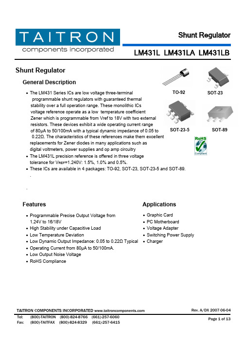
Shunt RegulatorShunt RegulatorGeneral Description• The LM431 Series ICs are low voltage three-terminalprogrammable shunt regulators with guaranteed thermal stability over a full operation range. These monolithic ICs voltage reference operate as a low temperature coefficientZener which is programmable from Vref to 18V with two external resistors. These devices exhibit a wide operating current rangeof 80µA to 50/100mA with a typical dynamic impedance of 0.05 to0.22Ω. The characteristics of these references make them excellent replacements for Zener diodes in many applications such asdigital voltmeters, power supplies and op amp circuitry• The LM431L precision reference is offered in three voltagetolerance for V REF =1.240V: 1.5%, 1.0% and 0.5%.• These ICs are available in 4 packages: TO-92, SOT-23, SOT-23-5 and SOT-89. . .Features Applications• Programmable Precise Output Voltage from 1.24V to 16/18V• High Stability under Capacitive Load• Low Temperature Deviation• Low Dynamic Output Impedance: 0.05 to 0.22Ω Typical • Operating Current from 80µA to 50/100mA. • Low Output Noise Voltage• RoHS ComplianceSOT-89SOT-23-5 SOT-23• Graphic Card• PC Motherboard • Voltage Adapter • Switching Power Supply • ChargerTO-92LM431L Ordering InformationPin ConfigurationOutline: ZTO-92Outline: NSOT-23Outline: N5SOT-23-5 Outline: KSOT-89LM431LBlock Diagram SymbolsAbsolute Maximum Ratings (Ta=25° C)(Full operating ambient temperature range applies unless otherwise noted.) SymbolDescription LM431L LM431LA LM431LBUnit V KA Cathode Voltage16 18 V I KA Cathode Current Range (Continuous) 50-100 ~ +100mAI REF Reference Input Current Range(Continuous)3 10 mAT J Operating Junction Temperature 150° C T OPR Operating Temperature Range -40 ~ 85-40 ~ 125 ° C T STGStorage Temperature Range-65 ~ 150° CZ:TO-92 700770 N:SOT-23 350 370N5:SOT-23-5550 370 P DPower DissipationK: SOT-89-770 mW Z:TO-92 180150 N:SOT-23 360 330N5:SOT-23-5230 250 Rth JAPackage Thermal ImpedanceK: SOT-89-50° C/WLM431L Electrical Characteristics(T A=25ºC, unless otherwise specified)LM431L LM431LALM431LBSymbol DescriptionMin.Typ. Max. Min.Typ.Max.Min.Typ.Max.UnitTestCircuitConditionsV REF Reference InputVoltage1.222 1.240 1.258 1.228 1.240 1.252 1.234 1.240 1.246 V Fig.1 V KA=V REF,I KA=10mA0-70° C - - - - 2 1- - 2 10-40-85° C- 7.0 20 - 3 10 - 3 10∆V REFReferenceInputVoltageDeviation -40-125° C- - - - 4 15 - 4 15mVFig.1(Note1)V KA=V REF,I KA=10mA ∆V REF/∆V KARatio of Change inReference InputVoltage to Change inCathode to AnodeVoltage- -0.6 -1.5 - -0.5 -1.5- -0.5 -1.5mV/V Fig.2IKA=10mA∆V KA=V KA(max)~V REFI REFReferenceInputCurrentTa=25°C- 0.15 0.3 - 0.150.4 - 0.150.4 µA Fig.2I KA=10mA, R1=10KΩ,R2=∞∆I REFReference InputCurrent DeviationOver TemperatureRange- 0.050.08 - 0.1 0.4 - 0.1 0.4 µA Fig.2I KA=10mA, R1=10KΩ,R2=∞I MIN Min. Cathode CurrentFor Regulation- 55 80 - 55 80 - 55 80 µA Fig.1 V KA=V REF- 2.6 1000 - 40 100- 40 100V KA= V KA(max),V REF=0VI OFF Off-State CathodeCurrent- - - - 10 50 - 10 50nA Fig.3V KA=6V, V REF=0V Z KA DynamicImpedance - 0.22 0.4 - 0.050.15- 0.050.15ΩFig.1(Note2)V KA=V REF,I KA=1.0mA~ I KA(max),f≤1.0KHz Fig.1- Test Circuit for V KA=V REF Fig.2- Test Circuit for V KA>V REFLM431LFig.3- Test Circuit for I OFFNote1: Note2:LM431LFig.4- V REF - T JJunction Temperature T J (° C)Fig.6- I K – V KA (1)Cathode Voltage V KA (V)Fig.5- I REF - T JJunction Temperature T J (° C)Typical Characteristics CurvesR e f e r e n c e I n p u t V o l t a g e V R E F (V )C a t h o d e C u r r e n t I K (m A )Fig.7- I K – V KA (2)Cathode Voltage V KA (V)R e f e r e n c e I n p u t C u r r e n t I R E F (n A )C a t h o d e C u r r e n t I K (µA )LM431LFig.8- G VO - fFrequency f (Hz)Fig.9- Pulse ResponseTime t (µs)V o l t a g e S w i n g (V )Fig.11- Z KA - fFrequency f (Hz)O p e n L o o p V o l t a g e G a i n G V O (d B )D y n a m i c I m p e d a n c e │Z K A │ (Ω)Fig.10- ∆V REF - T JJunction Temperature T J (° C)∆V R E F /∆V K A (m V /V )LM431L Typical ApplicationFig.12-Shunt RegulatorLM431L Typical Application (Continued)Fig.15- Precision 5V 1A RegulatorFig.16- PWM Converter with ReferenceLM431LDevice Marking CodeCircuit Tolerance SOT-23 (N) SOT-23-5 (N5)SOT-89 (K)Blank1.5%24A24A N/A A 1.0% EA7 E6A E41B LM431LB 0.5% EA6E5AE41ADimensions in inches (mm)TO-92LM431LSOT-23SOT-23-5LM431LSOT-89LM431L How to contact us:。
常用稳压芯片参数介绍

常用稳压芯片参数介绍线性稳压器件(输入输出电流相等,压降3V以上)型号稳压(V) 最大输出电流可替代型号79L05 -5V 100mA79L06 -6V 100mA79L08 -8V 100mALM7805 5V 1A L7805,LM340T5LM7806 6V 1A L7806LM7808 8V 1A L7808LM7809 9V 1A L7809LM7812 12V 1A L7812,LM340T12 LM7815 15V 1A L7815,LM340T15 LM7818 18V 1A L7815LM7824 24V 1A L7824LM7905 -5V 1A L7905LM7906 -6V 1A L7906,KA7906LM7908 -8V 1A L7908LM7909 -9V 1A L7909LM7912 -12V 1A L7912LM7915 -15V 1A L7915LM7918 -18V 1A L7918LM7924 -24V 1A L792478L05 5V 100mA78L06 6V 100mA78L08 8V 100ma78L09 9V 100ma78L12 12V 100ma78L15 15V 100ma78L18 18V 100ma78L24 24V 100ma开关稳压器件(电压转换效率高)型号说明最大输出电流LM1575T-3.3 3.3V简易开关电源稳压器 1A LM1575T-5.0 5V简易开关电源稳压器 1A LM1575T-12 12V简易开关电源稳压器 1A LM1575T-15 15V简易开关电源稳压器1A LM1575T-ADJ (可调1.23V~37V) 1ALM1575HVT-3.3 3.3V简易开关电源稳压器1A LM1575HVT-5.0 5V简易开关电源稳压器 1A LM1575HVT-12 12V简易开关电源稳压器 1A LM1575HVT-15 15V简易开关电源稳压器 1A LM1575HVT-ADJ (可调1.23V~37V) 1ALM2575T-3.3 3.3V简易开关电源稳压器1ALM2575T-5.0 5V简易开关电源稳压器 1ALM2575T-12 12V简易开关电源稳压器 1ALM2575T-15 15V简易开关电源稳压器1ALM2575T-ADJ (可调1.23V~ 37V) 1ALM2575HVT-3.3 3.3V简易开关电源稳压器1ALM2575HVT-5.0 5V简易开关电源稳压器1ALM2575HVT-12 12V简易开关电源稳压器1ALM2575HVT-15 15V简易开关电源稳压器1ALM2575HVT-ADJ 简易开关电源稳压器(可调1.23V~37V) 1A LM2576T-3.3 3.3V简易开关电源稳压器 3ALM2576T-5.0 5.0V简易开关电源稳压器 3ALM2576T-12 12V简易开关电源稳压器3ALM2576T-15 15V简易开关电源稳压器3ALM2576T-ADJ 简易开关电源稳压器(可调1.23V~37V) 3A LM2576HVT-3.3 3.3V简易开关电源稳压器3ALM2576HVT-5.0 5.0V简易开关电源稳压器3ALM2576HVT-12 12V简易开关电源稳压器3ALM2576HVT-15 15V简易开关电源稳压器3ALM2576HVT-ADJ 简易开关电源稳压器(可调1.23V~37V) 3A常用稳压IC大全7805 正5V稳压器(1A) 7805中文资料.pdf下载7806 正6V稳压器(1A)7808 正8V稳压器(1A)7809 正9V稳压议(1A)7809中文资料7812 正12V稳压器(1A) 7812中文资料7815 正15V稳压器(1A) 三端稳压器7815中文资料7818 正18V稳压器(1A)7824 正24V稳压器(1A)78L05 正5V稳压器(100ma)78L06 正6V稳压器(100ma)78L08 正8V稳压器(100ma)78L09 正9V稳压器(100ma)78L12 正12V稳压器(100ma)78L15 正15V稳压器(100ma)78L18 正18V稳压器(100ma)78L24 正24V稳压器(100ma)7905 负5V稳压器(1A)7906 负6V稳压器(1A)7908 负8V稳压器(1A)7909 负9V稳压器(1A)7912 负12V稳压器(1A)7915 负15V稳压器(1A)7918 负18V稳压器(1A)7924 负24V稳压器(1A)*************************************** 79L05 负5V稳压器(100ma)79L06 负6V稳压器(100ma)79L08 负8V稳压器(100ma)79L09 负9V稳压器(100ma)79L12 负12V稳压器(100ma)79L15 负15V稳压器(100ma)79L18 负18V稳压器(100ma)79L24 负24V稳压器(100ma)*************************************** LM1575T-3.3 3.3V简易开关电源稳压器(1A)LM1575T-5.0 5V简易开关电源稳压器(1A)LM1575T-12 12V简易开关电源稳压器(1A)LM1575T-15 15V简易开关电源稳压器(1A)LM1575T-ADJ 简易开关电源稳压器(1A可调1.23 to 37)LM1575HVT-3.3 3.3V简易开关电源稳压器(1A)LM1575HVT-5.0 5V简易开关电源稳压器(1A)LM1575HVT-12 12V简易开关电源稳压器(1A)LM1575HVT-15 15V简易开关电源稳压器(1A)LM1575HVT-ADJ 简易开关电源稳压器(1A可调1.23 to 37)**************************************LM2575T-3.3 3.3V简易开关电源稳压器(1A)LM2575T-5.0 5V简易开关电源稳压器(1A)LM2575T-12 12V简易开关电源稳压器(1A)LM2575T-15 15V简易开关电源稳压器(1A)LM2575T-ADJ 简易开关电源稳压器(1A可调1.23 to 37)LM257HVT-3.3 3.3V简易开关电源稳压器(1A)LM2575HVT-5.0 5V简易开关电源稳压器(1A)LM2575HVT-12 12V简易开关电源稳压器(1A)LM2575HVT-15 15V简易开关电源稳压器(1A)LM2575HVT-ADJ 简易开关电源稳压器(1A可调1.23 to 37)**************************************LM2576T-3.3 3.3V简易开关电源稳压器(3A)LM2576T-5.0 5.0V简易开关电源稳压器(3A)LM2576T-12 12V简易开关电源稳压器(3A)LM2576T-15 15V简易开关电源稳压器(3A)LM2576T-ADJ 简易开关电源稳压器(3A可调1.23V to 37V) LM2576HVT-3.3 3.3V简易开关电源稳压器(3A)LM2576HVT-5.0 5.0V简易开关电源稳压器(3A)LM2576HVT-12 12V简易开关电源稳压器(3A)LM2576HVT-15 15V简易开关电源稳压器(3A)LM2576HVT-ADJ 简易开关电源稳压器(3A可调1.23V to 37V) **************************************LM2930T-5.0 5.0V低压差稳压器LM2930T-8.0 8.0V低压差稳压器LM2931AZ-5.0 5.0V低压差稳压器(TO-92)LM2931T-5.0 5.0V低压差稳压器LM2931CT 3V to 29V低压差稳压器(TO-220,5PIN)LM2940CT-5.0 5.0V低压差稳压器LM2940CT-8.0 8.0V低压差稳压器LM2940CT-9.0 9.0V低压差稳压器LM2940CT-10 10V低压差稳压器LM2940CT-12 12V低压差稳压器LM2940CT-15 15V低压差稳压器**************************************LM123K 5V稳压器(3A)LM323K 5V稳压器(3A)LM117K 1.2V to 37V三端正可调稳压器(1.5A)LM317LZ 1.2V to 37V三端正可调稳压器(0.1A)LM317T 1.2V to 37V三端正可调稳压器(1.5A)LM317K 1.2V to 37V三端正可调稳压器(1.5A)LM133K 三端可调-1.2V to -37V稳压器(3.0A)LM333K 三端可调-1.2V to -37V稳压器(3.0A)LM337K 三端可调-1.2V to -37V稳压器(1.5A)LM337T 三端可调-1.2V to -37V稳压器(1.5A)LM337LZ 三端可调-1.2V to -37V稳压器(0.1A)LM150K 三端可调1.2V to 32V稳压器(3A)LM350K 三端可调1.2V to 32V稳压器(3A)LM350T 三端可调1.2V to 32V稳压器(3A)LM138K 三端正可调1.2V to 32V稳压器(5A)LM338T 三端正可调1.2V to 32V稳压器(5A)LM338K 三端正可调1.2V to 32V稳压器(5A)LM336-2.5 2.5V精密基准电压源LM336-5.0 5.0V精密基准电压源LM385-1.2 1.2V精密基准电压源LM385-2.5 2.5V精密基准电压源LM399H 6.9999V精密基准电压源LM431ACZ 精密可调2.5V to 36V基准稳压源LM723 高精度可调2V to 37V稳压器LM105 高精度可调4.5V to 40V稳压器LM305 高精度可调4.5V to40V稳压器MC1403 2.5V基准电压源MC34063 DC-DC直流变换器mc34063中文资料pdfSG3524 脉宽调制开关电源控制器sg3524中文资料TL431 精密可调2.5V to 36V基准稳压源tl431a pdf 中文资料TL494 脉宽调制开关电源控制器tl494中文资料pdf下载TL497 频率调制开关电源控制器tl497/tl497A pdf datasheetTL7705 电池供电/欠压控制器。
电源芯片 TL431.pdf
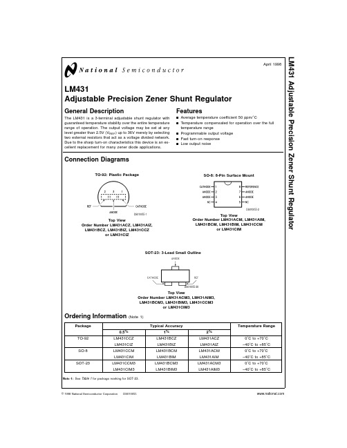
Minimum Cathode Current for Regulation Off-State Current Dynamic Output Impedance (Note 6)
(Figure 2 ) VZ from 10V to 36V
Note 3: TJ Max = 150˚C. Note 4: Ratings appy to ambient temperature at 25˚C. Above this temperature, derate the TO-92 at 6.2 mW/˚C, the SO-8 at 6.5 mW/˚C, and the SOT-23 at 2.2 mW/ ˚C.
(Soldering, 10 sec.)
265˚C
Internal Power Dissipation (Notes 3, 4) TO-92 Package SO-8 Package SOT-23 Package
0.78W 0.81W 0.28W
Cathode Voltage Continuous Cathode Current Reference Voltage Reference Input Current
or LM431CIM3
Ordering Information (Note 1)
Package TO-92 SO-8 SOT-23
0.5% LM431CCZ LM431CIZ LM431CCM LM431CIM LM431CCM3 LM431CIM3
Typical Accuracy 1%
LM431BCZ LM431BIZ LM431BCM LM431BIM LM431BCM3 LM431BIM3
用LM431做的延时开关
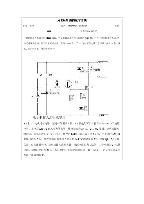
用LM431做的延时开关
作者:未知时间:2008-1-23 22:02:00更新:amks文章点击:127次
一般延时开关电路多用NE555来做,但是其最高工作电压只能达到18伏,有客户要求能工作在24伏的延时开关电路,用于汽车延时点火。我用LM431设计了一个延时开关电路,它可以工作在24伏,满足了客户的要求。电原理图如下:
R1和C1构成延时电路,延时时间要求1秒,C1要选用可以工作在-55~+125℃的钽电容。上电后LM431输入端为低电平,输出端约为23伏,Q1、Q2导通,点火线圈短时通电,通电电流约24安,通电一秒钟后LM431输入端升至2.5伏,由于这时LM431的输出约为2.伏,故在其输出端要串入稳压值为6.2V的稳压管Z2,这样Q1、Q2才能关断,点火线圈失电。点火线圈为感性负载,直流电阻约为1欧姆,工作电源为24伏蓄电池。实测电流约为25安。本电路的工作温度范围可达-40~+121℃,完全可以满足汽车电子电器的要求。
九、三端误差放大器TL431_按图索骥学修电动自行车_[共3页]
![九、三端误差放大器TL431_按图索骥学修电动自行车_[共3页]](https://img.taocdn.com/s3/m/07e36bfebd64783e08122b1d.png)
第5章 元器件的识读和检测技巧◆ 89 ◆ 表5-28 光电耦合器的开路检测步骤步骤① 如果怀疑光电耦合器漏电或性能不良时,需进行开路测量。
将光电耦合器从电路板上拆下,引脚朝下插在塑料泡沫板上步骤② 将数字万用表的挡位开关指向20M Ω挡,将红表笔搭在光电耦合器的2脚处,黑表笔搭在1脚处,观察万用表显示屏的数值应为“1.”,如若不是则说明该光电耦合器内的发光二极管不存在反向漏电现象步骤③ 将万用表的两表笔分别搭在光电耦合器的3脚和4脚处,观察万用表显示屏的数字应为“1”,如若不是则说明该光电耦合器内的光敏管存在漏电现象,交叉调换表笔重新测量光电耦合器内的光敏管也不应有漏电现象步骤④ 将万用表的红表笔搭在光电耦合器的1脚,黑表笔搭在光电耦合器的4脚,观察万用表显示屏的数值应为“1.”,表明光电耦合器内发光二极管和光敏管之间没有漏电现象;如果显示屏数值小于20M Ω,表明光电耦合器存在漏电现象若要检测光电耦合器的性能可参考光电耦合器的在路检测方法进行九、三端误差放大器TL4311.三端误差放大器TL431的结构和作用三端误差放大器TL431是可调分流器件,具有8脚扁平封装和3脚直插封装两种封装形式。
在充电器中常用的是3脚直插式,其外形如图5-14所示。
误差放大器TL431的3个引脚分别是阳极A 、阴极K 和控制极R 。
K 极接正电压、A 极接负电压时,R 极输入的取样电压高于2.5V 时,经内部反相放大器输出使K 极电压下降;当R 极输入的取样电压低于2.5V 时,K 极电压上升。
所以误差放大器TL431是将R 极输入取样信号与2.5V 基准电压比较后产生的误差信号反相放大来控制K 极的电位。
2.三端误差放大器TL431的识别由于三端误差放大器TL431外形和常用塑封3脚直插三极管1815较为相似,从外形上难以区分,但三端误差放大器的型号主要有TL431、LM431、KA431、K1A431、HA17431等几种,从型号可以看出均有431标识,这是区别其他三极管的重要标志,如图5-14所示。
- 1、下载文档前请自行甄别文档内容的完整性,平台不提供额外的编辑、内容补充、找答案等附加服务。
- 2、"仅部分预览"的文档,不可在线预览部分如存在完整性等问题,可反馈申请退款(可完整预览的文档不适用该条件!)。
- 3、如文档侵犯您的权益,请联系客服反馈,我们会尽快为您处理(人工客服工作时间:9:00-18:30)。
LM431Adjustable Precision Zener Shunt RegulatorGeneral DescriptionThe LM431is a 3-terminal adjustable shunt regulator with guaranteed temperature stability over the entire temperature range of operation.It is now available in a chip sized pack-age (4-Bump micro SMD)using National’s micro SMD pack-age technology.The output voltage may be set at any level greater than 2.5V (V REF )up to 36V merely by selecting two external resistors that act as a voltage divided network.Due to the sharp turn-on characteristics this device is an excel-lent replacement for many zener diode applications.Featuresn Average temperature coefficient 50ppm/˚Cn Temperature compensated for operation over the full temperature rangen Programmable output voltage n Fast turn-on response n Low output noisen LM431in micro SMD packagen See AN-1112for micro SMD considerationsConnection DiagramsNote:*NC =Not internally connected.Must be electrically isolated from therest of the circuit for the microSMD package.TO-92:Plastic PackageDS010055-1Top ViewSO-8:8-Pin Surface MountDS010055-2Top viewSOT-23:3-Lead Small OutlineDS010055-28Top View 4-Bump micro SMDDS010055-54Top View(bump side down)March 2002LM431Adjustable Precision Zener Shunt Regulator©2002National Semiconductor Corporation Ordering InformationPackage Typical Accuracy Order Number/Package MarkingTemperature Range Transport MediaNSC Drawing0.5%1%2%TO-92LM431CCZ/LM431CCZ LM431BCZ/LM431BCZ LM431ACZ/LM431ACZ 0˚C to +70˚CRailsZ03ALM431CIZ/LM431CIZLM431BIZ/LM431BIZ LM431AIZ/LM431AIZ −40˚C to +85˚C SO-8LM431CCM/431CCM LM431BCM/431BCM LM431ACM/LM431ACM 0˚C to +70˚CRails and Tape &ReelM08A LM431CIM/431CIMLM431BIM/431BIM LM431AIM/LM431AIM −40˚C to +85˚C SOT-23LM431CCM3/N1B LM431BCM3/N1D LM431ACM3/N1F 0˚C to +70˚CRails and Tape &ReelMF03A LM431CIM3N1ALM431BIM3N1CLM431AIM3N1E−40˚C to +85˚C micro SMD––LM431AIBPLM431AIBPX(Note 1)−40˚C to +85˚C250Units Tape and Reel3k Units Tape and ReelBPA04AFBNote 1:The micro SMD package marking is a 1digit manufacturing Date Code onlymicro SMD Top View Marking ExampleDS010055-56L M 431 2Symbol and Functional DiagramsDC Test CircuitsDS010055-99DS010055-55DS010055-4FIGURE 1.Test Circuit for V Z =V REFDS010055-5Note:V Z =V REF (1+R1/R2)+I REF •R1FIGURE 2.Test Circuit for V Z >V REFDS010055-6FIGURE 3.Test Circuit for Off-State CurrentLM4313Absolute Maximum Ratings (Note 2)If Military/Aerospace specified devices are required,please contact the National Semiconductor Sales Office/Distributors for availability and specifications.Storage Temperature Range −65˚C to +150˚C Operating Temperature Range Industrial (LM431xI)−40˚C to +85˚C Commercial (LM431xC)0˚C to +70˚C Soldering InformationInfrared or Convection (20sec.)235˚CWave Soldering (10sec.)260˚C (lead temp.)Cathode Voltage37VContinuous Cathode Current−10mA to +150mAReference Voltage−0.5V Reference Input Current10mA Internal Power Dissipation (Notes 3,4)TO-92Package SO-8Package SOT-23Package 0.78W 0.81W 0.28W micro SMD Package0.30WOperating ConditionsMin Max Cathode Voltage V REF 37V Cathode Current1.0mA100mALM431Electrical CharacteristicsT A =25˚C unless otherwise specified Symbol ParameterConditionsMin Typ Max Units V REFReference VoltageV Z =V REF ,I I =10mA 2.4402.4952.550VLM431A (Figure 1)V Z =V REF ,I I =10mA 2.4702.4952.520VLM431B (Figure 1)V Z =V REF ,I I =10mA 2.4852.5002.510VLM431C (Figure 1)V DEVDeviation of Reference Input Voltage Over V Z =V REF ,I I =10mA,8.017mVTemperature (Note 5)T A =Full Range (Figure 1)Ratio of the Change in Reference Voltage I Z =10mAV Z from V REF to 10V −1.4−2.7mV/Vto the Change in Cathode Voltage(Figure 2)V Z from 10V to 36V−1.0−2.0I REF Reference Input CurrentR 1=10k Ω,R 2=∞, 2.04.0µA I I =10mA (Figure 2)∝I REFDeviation of Reference Input Current over R 1=10k Ω,R 2=∞,TemperatureI I =10mA,0.4 1.2µA T A =Full Range (Figure 2)I Z(MIN)Minimum Cathode Current for Regulation V Z =V REF (Figure 1)0.4 1.0mA I Z(OFF)Off-State CurrentV Z =36V,V REF =0V (Figure 3)0.31.0µA r ZDynamic Output Impedance (Note 6)V Z =V REF ,LM431A,0.75ΩFrequency =0Hz (Figure 1)V Z =V REF ,LM431B,LM431C 0.50ΩFrequency =0Hz (Figure 1)Note 2:Absolute Maximum Ratings indicate limits beyond which damage to the device may occur.Electrical specifications do not apply when operating the device beyond its rated operating conditions.Note 3:T J Max =150˚C.Note 4:Ratings apply to ambient temperature at 25˚C.Above this temperature,derate the TO-92at 6.2mW/˚C,the SO-8at 6.5mW/˚C,the SOT-23at 2.2mW/˚C and the micro SMD at 3mW/˚C.Note 5:Deviation of reference input voltage,V DEV ,is defined as the maximum variation of the reference input voltage over the full temperature range.L M 431 4LM431Electrical Characteristics(Continued)Where:T 2−T 1=full temperature change (0-70˚C).∝V REF can be positive or negative depending on whether the slope is positive or negative.Example:V DEV =8.0mV,V REF =2495mV,T 2−T 1=70˚C,slope is positive.Note 6:The dynamic output impedance,r Z ,is defined as:When the device is programmed with two external resistors,R1and R2,(see Figure 2),the dynamic output impedance of the overall circuit,r Z ,is defined as:Equivalent CircuitDS010055-7The average temperature coefficient of the reference input voltage,∝V REF ,is defined as:DS010055-3LM4315Typical Performance CharacteristicsInput Current vs V ZDS010055-29Thermal InformationDS010055-30Input Current vs V ZDS010055-31Dynamic Impedance vs FrequencyDS010055-9DS010055-10Stability Boundary ConditionsDS010055-11Note:The areas under the curves represent conditions that may cause the device to oscillate.For curves B,C,and D,R2and V +were adjusted to establish the initial V Z and I Z conditions with C L =0.V +and C L were then adjusted to determine the ranges of stability.Test Circuit for Curve A Above DS010055-12Test Circuit for Curves B,C and D AboveDS010055-13L M 431 6Typical ApplicationsShunt RegulatorDS010055-14Single Supply Comparator withTemperature Compensated ThresholdDS010055-15Series RegulatorDS010055-16Output Control of a ThreeTerminal Fixed RegulatorDS010055-17Higher Current Shunt RegulatorDS010055-18Crow BarDS010055-19LM4317Typical Applications(Continued)Over Voltage/Under VoltageProtection CircuitDS010055-20Voltage MonitorDS010055-21L M 431 8Typical Applications(Continued)Application Info1.0MountingTo ensure that the geometry of the micro SMD packagemaintains good physical contact with the printed circuitboard,pin A1(NC)must be soldered to the pcb.Please seeAN-1112for more detailed information regarding boardmounting techniques for the micro SMD package.2.0LM431micro SMD Light SensitivityWhen the LM431micro SMD package is exposed to brightsunlight,normal office fluorescent light,and other LED’s andlasers,it operates within the guaranteed limits specified inthe electrical characteristics table.Delay TimerDS010055-22Current Limiter or Current SourceDS010055-23Constant Current SinkDS010055-24LM4319Physical Dimensionsinches (millimeters)unless otherwise notedNS Package Number M08ASOT-23Molded Small Outline Transistor Package (M3)NS Package Number MF03AL M 431 10LM431 Physical Dimensions inches(millimeters)unless otherwise noted(Continued)11Physical Dimensions inches(millimeters)unless otherwise noted(Continued)LIFE SUPPORT POLICYNATIONAL’S PRODUCTS ARE NOT AUTHORIZED FOR USE AS CRITICAL COMPONENTS IN LIFE SUPPORT DEVICES OR SYSTEMS WITHOUT THE EXPRESS WRITTEN APPROVAL OF THE PRESIDENT AND GENERAL COUNSEL OF NATIONAL SEMICONDUCTOR CORPORATION.As used herein:1.Life support devices or systems are devices orsystems which,(a)are intended for surgical implantinto the body,or(b)support or sustain life,andwhose failure to perform when properly used inaccordance with instructions for use provided in thelabeling,can be reasonably expected to result in asignificant injury to the user.2.A critical component is any component of a lifesupport device or system whose failure to performcan be reasonably expected to cause the failure ofthe life support device or system,or to affect itssafety or effectiveness.National SemiconductorCorporationAmericasEmail:support@National SemiconductorEuropeFax:+49(0)180-5308586Email:europe.support@Deutsch Tel:+49(0)6995086208English Tel:+44(0)8702402171Français Tel:+33(0)141918790National SemiconductorAsia Pacific CustomerResponse GroupTel:65-2544466Fax:65-2504466Email:ap.support@National SemiconductorJapan Ltd.Tel:81-3-5639-7560Fax:81-3-5639-7507 NOTES:UNLESS OTHERWISE SPECIFIED1.EPOXY COATING2.63Sn/37Pb EUTECTIC BUMP3.RECOMMEND NON-SOLDER MASK DEFINED LANDING PAD.4.PIN A1IS ESTABLISHED BY LOWER LEFT CORNER WITH RESPECT TO TEXT ORIENTATION.REMAINING PINS ARENUMBERED.5.XXX IN DRAWING NUMBER REPRESENTS PACKAGE SIZE VARIATION WHERE X1IS PACKAGE WIDTH,X2ISPACKAGE LENGTH AND X3IS PACKAGE HEIGHT.6.REFERENCE JEDEC REGISTRATION MO-211,VARIATION BA.4-Bump micro SMDX1=0.777X2=0.904X3=0.850NS Package Number BPA04AFBLM431AdjustablePrecisionZenerShuntRegulatorNational does not assume any responsibility for use of any circuitry described,no circuit patent licenses are implied and National reserves the right at any time without notice to change said circuitry and specifications.。
