AutomationDirect发布IronHorse GSD1系列直流驱动器
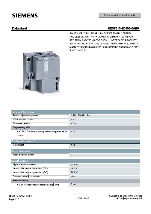
Siemens ET 200SP CPU 1510SP-1 PN 产品说明书
FB ● Number range ● Size, max.
FC ● Number range ● Size, max.
OB ● Size, max. ● Number of free cycle OBs ● Number of time alarm OBs
6ES7510-1DJ01-0AB0 Page 2/10
CPU processing times for bit operations, typ. for word operations, typ. for fixed point arithmetic, typ. for floating point arithmetic, typ.
CPU-blocks Number of elements (total) DB ● Number range
Data sheet
Show actual product details
6ES7510-1DJ01-0AB0
SIMATIC DP, CPU 1510SP-1 PN FOR ET 200SP, CENTRAL PROCESSING UNIT WITH WORKING MEMORY 100 KB FOR PROGRAM AND 750 KB FOR DATA, 1. INTERFACE: PROFINET IRT WITH 3 PORT SWITCH, 72 NS BIT-PERFORMANCE, SIMATIC MEMORY CARD NECESSARY, BUSADAPTER NECESSARY FOR PORT 1 AND 2
Counters, timers and their retentivity S7 counter ● Number Retentivity — adjustable IEC counter ● Number Retentivity — adjustable S7 times ● Number Retentivity — adjustable IEC timer ● Number Retentivity — adjustable
欧姆龙 3G3MV 系列通用变频器 说明书

限制运转方向 (n006)................................................................ 51 阶梯形改变速度........................................................................ 51 低速运行.................................................................................... 52 调整速度设定信号.................................................................... 53 限制速度.................................................................................... 54 使用 2 套加减速时间................................................................ 54 瞬时停电复电后的自动再起动 (n081).................................... 55 平滑运行 (n023)........................................................................ 56 力矩的检测................................................................................ 56 检测频率 (n095)........................................................................ 58 避免共振 (n083 ~ n086).......................................................... 59 故障时自动复位并继续运行 (n082)........................................ 59 自由滑行中的电机无抖动运转................................................ 60 加减速暂停................................................................................ 61 使用频率表,电流表 (n066).................................................... 62 校正频率表·电流表 (n067).................................................... 62 脉冲序列信号输出作为模拟量输出 (AM-AC) 使用.............. 63 降低杂波和漏电流 (n080)........................................................ 65 STOP 键的有效 / 无效的选择 (n007) ...................................... 67 ■ 选择停止方法............................................................................ 67 选择停止方法 (n005)................................................................ 67 进行直流制动............................................................................ 68 ■ 与外部接口回路组合................................................................ 69 使用输入信号............................................................................ 69 使用多功能模拟量输入功能 (n007,n078,n079)...................... 72 使用输出信号 (n057,n058,n059) .............................................. 74 ■ 以电流指令输入设定频率........................................................ 75 ■ 用脉冲序列输入设定频率指令................................................ 77 防止电机失速............................................................................ 78 运行中失速防止的功能 UP ..................................................... 79 ■ 减少电机的速度变动................................................................ 81 补偿电机的转差 (V/f 控制模式 n002=0 的场合 ) .................. 81
启英泰伦CI-D0XGS01J 模块数据手册说明书

Chipintelli Technology Co.,Ltd.CONFIDENTIAL ALL RIGHTS RESERVED.This document is not to be reproduced,modified,adapted,published,translated in any material form in whole or in part nor disclosed to any third party without the priorwritten permission of Chipintelli Technology Co.,Ltd.文档分类:硬件开发文档名称:CI-D0XGS01J 模块数据手册文档日期:2022/09/08请点击下载PDF文档CI-D0XGS01J模块数据手册模块介绍概述本模块是针对低成本离线语音应用方案开发的一款通用、便携、低功耗高性能的语音识别模块,型号为:CI-D0XGS01J,主芯片为CI1301、CI1302、CI1303,可以实现最大300条(型号不同支持的词条数不同)以下的离线命令词识别。
图1 模块框图该模块具有以下特点:模块体积小巧,长宽为30mm×40mm,工作电压为3.6V-5.5V,板载功放,带一路麦克风、一路喇叭和一路5V电源及UART的接口,模块插入麦克风和喇叭直接供电即可使用,也可以直接通过接插件将UART连接到产品主控板,由产品主控板的5V电源进行供电,UART通信或GPIO控制,无需焊接。
模块包含2个3.5mm螺丝孔,方便固定及安装。
模块主芯片支持离线神经网络计算,支持单麦克风降噪增强,360度全方位拾音,可抑制环境噪音,保证嘈杂环境中语音识别的准确性。
使用本模块进行离线语音识别不依赖网络,时延小,性能高,可实现97%以上的高识别率,10米超远距离识别,响应时间最快达到0.2S。
模块可以应用到有能耗等级要求的产品和电池类产品中。
卡洛加瓦齐有限公司RM1D系列直流开关固态继电器说明书
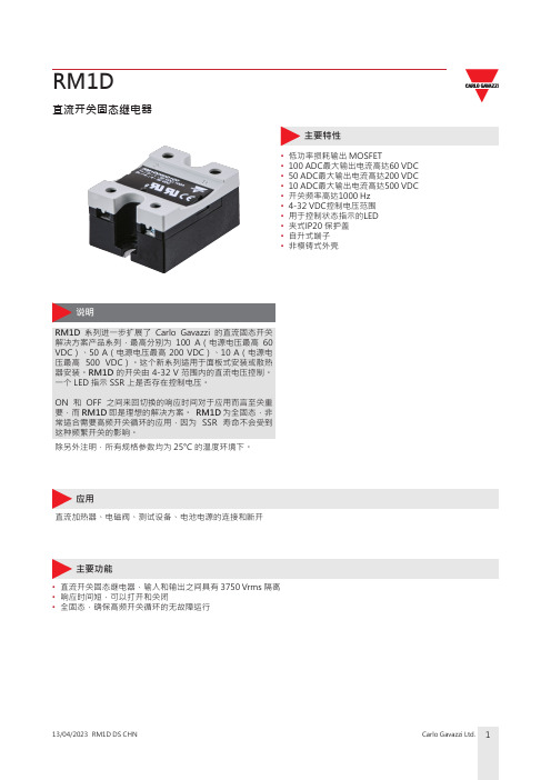
直流开关固态继电器主要特性• 低功率损耗输出 MOSFET• 100 ADC最大输出电流高达60 VDC • 50 ADC最大输出电流高达200 VDC • 10 ADC最大输出电流高达500 VDC • 开关频率高达1000 Hz • 4-32 VDC控制电压范围• 用于控制状态指示的LED • 夹式IP20 保护盖• 自升式端子•非模铸式外壳RM1D 系列进一步扩展了 Carlo Gavazzi 的直流固态开关解决方案产品系列,最高分别为 100 A(电源电压最高 60 VDC)、50 A(电源电压最高 200 VDC)、10 A(电源电压最高 500 VDC)。
这个新系列适用于面板式安装或散热器安装。
RM1D 的开关由 4-32 V 范围内的直流电压控制。
一个 LED 指示 SSR 上是否存在控制电压。
ON 和 OFF 之间来回切换的响应时间对于应用而言至关重要,而 RM1D 即是理想的解决方案。
RM1D 为全固态,非常适合需要高频开关循环的应用,因为 SSR 寿命不会受到这种频繁开关的影响。
除另外注明,所有规格参数均为 25°C 的温度环境下。
RM1D应用直流加热器、电磁阀、测试设备、电池电源的连接和断开主要功能• 直流开关固态继电器,输入和输出之间具有 3750 Vrms 隔离 • 响应时间短,可以打开和关闭• 全固态,确保高频开关循环的无故障运行订购代码输入代码,输入相应的选项而不是 . 有关有效的部件号,请参阅选择指南部分。
选型指南Carlo Gavazzi 兼容组件补充读物结构特性通用数据尺寸Fig. 1 RM1D尺寸除非另有说明,否则尺寸均为毫米性能输出控制打开tt onttt关掉t offFig. 2 响应时间特性Fig. 3输入电压与输入电流的关系曲线02468101214161848121620242832输入电流 (m A D C )输入电压 (VDC)1: 工作温度低于 -20°C 时,吸合电压升高至 5.5 VDC2: 在高开关频率下,输出电流会降低。
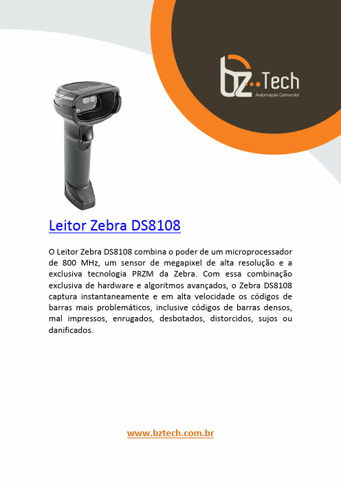
斑马技术公司DS8108数字扫描仪产品参考指南说明书
罗克韦尔自动化 FactoryTalk Alarms and Events 系统配置指南说明书

章节 4
在 Studio 5000 控制器中定 义基于设备的报警
控制器连接丢失时的报警缓冲 ............................................................... 27 在开始之前 ................................................................................................28 先决条件 ....................................................................................................28 遵照下列步骤............................................................................................ 28 定义基于 Logix 标签的报警................................................................. 28
警告:标识可能导致暴露于危险环境从而造成人员伤亡、财物损害或经济损失的做法或环境的相关信息。
注意:标识可能导致人员伤亡、财物损害或经济损失的做法或环境的相关信息。注意事项可帮助您识别危险,避开 危险,以及意识到后果。
重要 标识对成功应用和了解产品至关重要的信息。 还会在设备上或内部使用标签来提供具体预防措施。
典型的独立系统 ................................................................................. 24 安装 FactoryTalk 软件.................................................................... 25 安装 Microsoft SQL Server .............................................................. 26
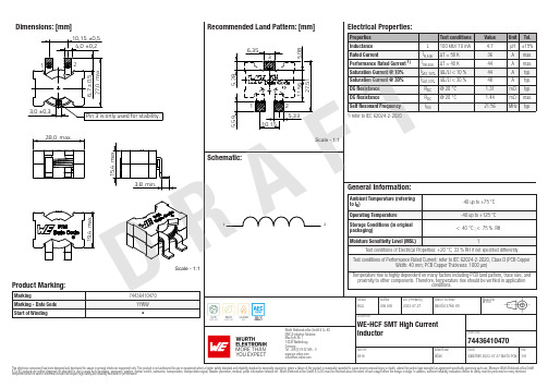
Siemens 电磁铁产品说明书.pdf_1718614415.77191
Dimensions: [mm]Scale - 1:17443641047074436410470744364104707443641047074436410470T e m p e r a t u r eT pT L74436410470Cautions and Warnings:The following conditions apply to all goods within the product series of WE-HCF of Würth Elektronik eiSos GmbH & Co. KG:General:•This electronic component was designed and manufactured for use in general electronic equipment.•Würth Elektronik must be asked for written approval (following the PPAP procedure) before incorporating the components into any equipment in fields such as military, aerospace, aviation, nuclear control, submarine, transportation (automotive control, train control, ship control), transportation signal, disaster prevention, medical, public information network, etc. where higher safety and reliability are especially required and/or if there is the possibility of direct damage or human injury.•Electronic components that will be used in safety-critical or high-reliability applications, should be pre-evaluated by the customer. •The component was designed and manufactured to be used within the datasheet specified values. If the usage and operation conditions specified in the datasheet are not met, the wire insulation may be damaged or dissolved.•Do not drop or impact the components, as the core may flake apart.•Würth Elektronik products are qualified according to international standards, which are listed in each product reliability report. Würth Elektronik does not guarantee any customer qualified product characteristics beyond Würth Elektroniks’ specifications, for its validity and sustainability over time.•The customer is responsible for the functionality of their own products. All technical specifications for standard products also apply to customer specific products.Product specific:Soldering:•The solder profile must comply with the Würth Elektronik technical soldering specification. All other profiles will void the warranty. •All other soldering methods are at the customers’ own risk.Cleaning and Washing:•Washing agents used during the production to clean the customer application may damage or change the characteristics of the wire insulation, marking or plating. Washing agents may have a negative effect on the long-term functionality of the product. Potting:•If the product is potted in the costumer application, the potting material may shrink or expand during and after hardening. Shrinking could lead to an incomplete seal, allowing contaminants into the core. Expansion could damage the core or wire contacts. Werecommend a manual inspection after potting to avoid these effects. Storage Conditions:• A storage of Würth Elektronik products for longer than 12 months is not recommended. Within other effects, the terminals may suffer degradation, resulting in bad solderability. Therefore, all products shall be used within the period of 12 months based on the day of shipment.•Do not expose the components to direct sunlight.•The storage conditions in the original packaging are defined according to DIN EN 61760-2.Packaging:•The packaging specifications apply only to purchase orders comprising whole packaging units. If the ordered quantity exceeds or is lower than the specified packaging unit, packaging in accordance with the packaging specifications cannot be ensured. Handling:•Violation of the technical product specifications such as exceeding the nominal rated current will void the warranty•Applying currents with audio-frequency signals may result in audible noise due to the magnetostrictive material properties. •Due to heavy weight of the components, strong forces and high accelerations may have the effect to damage the electrical connection or to harm the circuit board and will void the warranty.These cautions and warnings comply with the state of the scientific and technical knowledge and are believed to be accurate and reliable.However, no responsibility is assumed for inaccuracies or incompletenessWürth Elektronik eiSos GmbH & Co. KGEMC & Inductive SolutionsMax-Eyth-Str. 174638 WaldenburgGermanyCHECKED REVISION DATE (YYYY-MM-DD)GENERAL TOLERANCE PROJECTIONMETHODElGa005.0002023-07-27DIN ISO 2768-1mDESCRIPTIONWE-HCF SMT High CurrentInductor ORDER CODE74436410470SIZE/TYPE BUSINESS UNIT STATUS PAGE D RA FTImportant NotesThe following conditions apply to all goods within the product range of Würth Elektronik eiSos GmbH & Co. KG:1. General Customer ResponsibilitySome goods within the product range of Würth Elektronik eiSos GmbH & Co. KG contain statements regarding general suitability for certain application areas. These statements about suitability are based on our knowledge and experience of typical requirements concerning the areas, serve as general guidance and cannot be estimated as binding statements about the suitability for a customer application. The responsibility for the applicability and use in a particular customer design is always solely within the authority of the customer. Due to this fact it is up to the customer to evaluate, where appropriate to investigate and decide whether the device with the specific product characteristics described in the product specification is valid and suitable for the respective customer application or not.2. Customer Responsibility related to Specific, in particular Safety-Relevant ApplicationsIt has to be clearly pointed out that the possibility of a malfunction of electronic components or failure before the end of the usual lifetime cannot be completely eliminated in the current state of the art, even if the products are operated within the range of the specifications.In certain customer applications requiring a very high level of safety and especially in customer applications in which the malfunction or failure of an electronic component could endanger human life or health it must be ensured by most advanced technological aid of suitable design of the customer application that no injury or damage is caused to third parties in the event of malfunction or failure of an electronic component. Therefore, customer is cautioned to verify that data sheets are current before placing orders. The current data sheets can be downloaded at .3. Best Care and AttentionAny product-specific notes, cautions and warnings must be strictly observed. Any disregard will result in the loss of warranty.4. Customer Support for Product SpecificationsSome products within the product range may contain substances which are subject to restrictions in certain jurisdictions in order to serve specific technical requirements. Necessary information is available on request. In this case the field sales engineer or the internal sales person in charge should be contacted who will be happy to support in this matter.5. Product R&DDue to constant product improvement product specifications may change from time to time. As a standard reporting procedure of the Product Change Notification (PCN) according to the JEDEC-Standard inform about minor and major changes. In case of further queries regarding the PCN, the field sales engineer or the internal sales person in charge should be contacted. The basic responsibility of the customer as per Section 1 and 2 remains unaffected.6. Product Life CycleDue to technical progress and economical evaluation we also reserve the right to discontinue production and delivery of products. As a standard reporting procedure of the Product Termination Notification (PTN) according to the JEDEC-Standard we will inform at an early stage about inevitable product discontinuance. According to this we cannot guarantee that all products within our product range will always be available. Therefore it needs to be verified with the field sales engineer or the internal sales person in charge about the current product availability expectancy before or when the product for application design-in disposal is considered. The approach named above does not apply in the case of individual agreements deviating from the foregoing for customer-specific products.7. Property RightsAll the rights for contractual products produced by Würth Elektronik eiSos GmbH & Co. KG on the basis of ideas, development contracts as well as models or templates that are subject to copyright, patent or commercial protection supplied to the customer will remain with Würth Elektronik eiSos GmbH & Co. KG. Würth Elektronik eiSos GmbH & Co. KG does not warrant or represent that any license, either expressed or implied, is granted under any patent right, copyright, mask work right, or other intellectual property right relating to any combination, application, or process in which Würth Elektronik eiSos GmbH & Co. KG components or services are used.8. General Terms and ConditionsUnless otherwise agreed in individual contracts, all orders are subject to the current version of the “General Terms and Conditions of Würth Elektronik eiSos Group”, last version available at .Würth Elektronik eiSos GmbH & Co. KGEMC & Inductive SolutionsMax-Eyth-Str. 174638 WaldenburgGermanyCHECKED REVISION DATE (YYYY-MM-DD)GENERAL TOLERANCE PROJECTIONMETHODElGa005.0002023-07-27DIN ISO 2768-1mDESCRIPTIONWE-HCF SMT High CurrentInductor ORDER CODE74436410470SIZE/TYPE BUSINESS UNIT STATUS PAGE D RA FT。
MOXA MGate 5111系列产品说明书
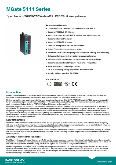
MGate5111Series1-port Modbus/PROFINET/EtherNet/IP to PROFIBUS slave gatewaysFeatures and Benefits•Converts Modbus,PROFINET,or EtherNet/IP to PROFIBUS•Supports PROFIBUS DP V0slave•Supports Modbus RTU/ASCII/TCP master/client and slave/server•Supports EtherNet/IP Adapter•Supports PROFINET IO device•Effortless configuration via web-based wizard•Built-in Ethernet cascading for easy wiring•Embedded traffic monitoring/diagnostic information for easy troubleshooting•Status monitoring and fault protection for easy maintenance•microSD card for configuration backup/duplication and event logs•Supports redundant dual DC power inputs and1relay output•Serial port with2kV isolation protection•-40to75°C wide operating temperature models available•Security features based on IEC62443CertificationsIntroductionMGate5111industrial Ethernet gateways convert data from Modbus RTU/ASCII/TCP,EtherNet/IP,or PROFINET to PROFIBUS protocols.All models are protected by a rugged metal housing,are DIN-rail mountable,and offer built-in serial isolation.Modbus is one of the most widely used industrial communication protocols,and EtherNet/IP,PROFINET,and PROFIBUS are commonly used in factory automation and process automation.The MGate5111supports both Modbus RTU/ASCII/TCP master and slave modes,so that you can easily connect your Modbus device to PROFIBUS PLCs or DCSs,such as Siemens PLCs.For system integration,the MGate5111can connect to EtherNet/IP PLC/SCADA systems,such as Rockwell Automation PLCs,to PROFIBUS PLC/ DCS systems,or between a new Siemens PLC system that supports PROFINET to an existing PROFIBUS system.The MGate5111gateways are designed for easy configuration and quick maintenance.A handy web console can be used to implement remote maintenance tasks,and the configuration wizard UI lets you quickly set up your gateway.A comprehensive collection of troubleshooting tools reduce configuration time and system downtime.The rugged design is suitable for industrial applications,such as factory automation,power,oil and gas,water and wastewater, and other process automation industries.Easy ConfigurationThe MGate5111Series has a user-friendly interface that lets you quickly set up protocol conversion routines for most applications,doing away with what were often time-consuming tasks in which users had to implement detailed parameter configurations one by one.With Quick Setup,you can easily access protocol conversion modes and finish the configuration in a few steps.The MGate5111supports a web console and Telnet console for remote maintenance.Encryption communication functions,including HTTPS and SSH,are supported to provide better network security.In addition,system monitoring functions are provided to record network connections and system log events.A Variety of Maintenance FunctionsThe MGate5111supports Protocol Diagnose and Traffic Monitor for easy troubleshooting,especially during the installation munication issues caused by incorrect software parameters,such as slave IDs and register addresses,or incorrect command configurations,can be fished out with Protocol Diagnose and Traffic Monitoring,which let you capture and check data to easily identify root causes.MGate5111gateways also support status monitoring and fault protection functions.The status monitoring function notifies a PLC/DCS/SCADA system when a Modbus device gets disconnected or does not respond,in which case the process PLC/DCS gets the status of each end device and then issues alarms to notify operators.When a PROFIBUS cable gets disconnected,the fault protection function executes actions on end devices identified by a predefined value set by the user.SpecificationsEthernet Interface10/100BaseT(X)Ports(RJ45connector)2Auto MDI/MDI-X connectionMagnetic Isolation Protection 1.5kV(built-in)Ethernet Software FeaturesIndustrial Protocols Modbus TCP Client(Master),Modbus TCP Server(Slave),PROFINET IO Device,EtherNet/IP AdapterConfiguration Options Web Console(HTTP/HTTPS),Device Search Utility(DSU),Telnet Console Management ARP,DHCP Client,DNS,HTTP,HTTPS,SMTP,SNMP Trap,SNMPv1/v2c/v3,TCP/IP,Telnet,SSH,UDP,NTP ClientMIB RFC1213,RFC1317Time Management NTP ClientSerial InterfaceConsole Port RS-232(TxD,RxD,GND),8-pin RJ45(115200,n,8,1)No.of Ports1Connector DB9maleSerial Standards RS-232/422/485Baudrate50bps to921.6kbpsData Bits7,8Parity None,Even,Odd,Space,MarkStop Bits1,2Flow Control RTS Toggle(RS-232only),RTS/CTSRS-485Data Direction Control ADDC®(automatic data direction control)Pull High/Low Resistor for RS-4851kilo-ohm,150kilo-ohmsTerminator for RS-485120ohmsIsolation2kV(built-in)Serial SignalsRS-232TxD,RxD,RTS,CTS,DTR,DSR,DCD,GNDRS-422Tx+,Tx-,Rx+,Rx-,GNDRS-485-2w Data+,Data-,GNDRS-485-4w Tx+,Tx-,Rx+,Rx-,GNDSerial Software FeaturesConfiguration Options Serial ConsoleIndustrial Protocols PROFIBUS DP-V0Slave,Modbus RTU/ASCII Master,Modbus RTU/ASCII SlaveModbus RTU/ASCIIMode Master,SlaveFunctions Supported1,2,3,4,5,6,15,16,23Max.No.of Commands128Input Data Size2048bytesOutput Data Size2048bytesModbus TCPMode Client(Master),Server(Slave)Functions Supported1,2,3,4,5,6,15,16,23Max.No.of Client Connections16Max.No.of Server Connections32Max.No.of Commands128Input Data Size2048bytesOutput Data Size2048bytesPROFIBUS InterfaceIndustrial Protocols PROFIBUS DPNo.of Ports1Connector DB9femaleBaudrate9600bps to12MbpsIsolation2kV(built-in)Signals PROFIBUS D+,PROFIBUS D-,RTS,Signal Common,5VPROFIBUSRotary Switch PROFIBUS addresses0-99(addresses100-125supported through softwareconfiguration)Mode DP-V0SlaveMax.No.of Master Connections1Max.No.of PROFIBUS I/O Modules24Input Data Size244bytesOutput Data Size244bytesPROFINETMode IO DeviceMax.No.of IO Controller Connections1(for read/write)Input Data Size512bytesOutput Data Size512bytesEtherNet/IPMode AdapterCIP Objects Supported Identity,Message Router,Assembly,Connection Manager,TCP/IP interface,Ethernetlink,PortMax.No.of Scanner Connections1(for read-only),1(for read/write)Input Data Size496bytesOutput Data Size496bytesMemorymicroSD Slot Up to32GB(SD2.0compatible)Power ParametersInput Voltage12to48VDCInput Current416mA@12VDCPower Connector Spring-type Euroblock terminalRelaysContact Current Rating Resistive load:2A@30VDCPhysical CharacteristicsHousing MetalIP Rating IP30Dimensions45.8x105x134mm(1.8x4.13x5.28in)Weight589g(1.30lb)Environmental LimitsOperating Temperature MGate5111:0to60°C(32to140°F)MGate5111-T:-40to75°C(-40to167°F)Storage Temperature(package included)-40to85°C(-40to185°F)Ambient Relative Humidity5to95%(non-condensing)Standards and CertificationsSafety EN60950-1,UL61010-2-201EMC EN61000-6-2/-6-4EMI CISPR32,FCC Part15B Class AEMS IEC61000-4-2ESD:Contact:8kV;Air:15kVIEC61000-4-3RS:80MHz to1GHz:10V/mIEC61000-4-4EFT:Power:4kV;Signal:4kVIEC61000-4-5Surge:Power:2kV;Signal:2kVIEC61000-4-6CS:150kHz to80MHz:10V/m;Signal:10V/mIEC61000-4-8PFMFHazardous Locations ATEX,Class I Division2,IECExFreefall IEC60068-2-32Shock IEC60068-2-27Vibration IEC60068-2-6,IEC60068-2-64MTBFTime718,131hrsStandards Telcordia SR332WarrantyWarranty Period5yearsDetails See /warrantyPackage ContentsDevice1x MGate5111Series gatewayInstallation Kit1x DIN-rail kitDocumentation1x quick installation guide1x warranty cardDimensionsOrdering InformationModel Name Operating Temp. MGate51110to60°C MGate5111-T-40to75°C Accessories(sold separately)CablesCBL-F9M9-150DB9female to DB9male serial cable,1.5mCBL-F9M9-20DB9female to DB9male serial cable,20cmCBL-RJ45F9-150RJ45to DB9female serial cable,1.5mCBL-RJ45SF9-150RJ45to DB9female serial shielded cable,1.5mConnectorsMini DB9F-to-TB DB9female to terminal block connectorWall-Mounting KitsWK-51-01Wall-mounting kit,2plates,6screws,51.6x67x2mmPower CordsCBL-PJTB-10Non-locking barrel plug to bare-wire cable©Moxa Inc.All rights reserved.Updated Nov07,2019.This document and any portion thereof may not be reproduced or used in any manner whatsoever without the express written permission of Moxa Inc.Product specifications subject to change without notice.Visit our website for the most up-to-date product information.。
RMDS 系列直流伺服电机驱动器用户手册说明书
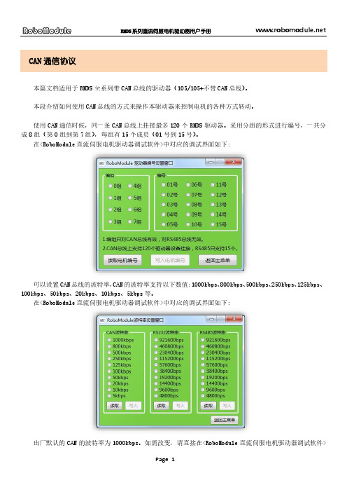
CAN通信协议本篇文档适用于RMDS全系列带CAN总线的驱动器(105/105+不带CAN总线)。
本段介绍如何使用CAN总线的方式来操作本驱动器来控制电机的各种方式转动。
使用CAN通信时候,同一条CAN总线上挂接最多120个RMDS驱动器。
采用分组的形式进行编号,一共分成8组(第0组到第7组),每组有15个成员(01号到15号)。
在<RoboModule直流伺服电机驱动器调试软件>中对应的调试界面如下:可以设置CAN总线的波特率,CAN的波特率支持以下数值:1000kbps、800kbps、500kbps、250kbps、125kbps、100kbps、50kbps、20kbps、10kbps、5kbps等。
在<RoboModule直流伺服电机驱动器调试软件>中对应的调试界面如下:出厂默认的CAN的波特率为1000kbps。
如需改变,请直接在<RoboModule直流伺服电机驱动器调试软件>上操作修改即可。
另外,RMDS系列驱动器的所有CAN消息都是数据帧、标准帧、帧长度为8,这些不可修改。
使用CAN总线来操作驱动器之前,必须先使用RS232串口线将驱动器连接至电脑,来进行参数调试,所涉及的调试内容有:1.调节电机和编码器的方向,确定电机转动的正方向,并使驱动器能够正常的进行调速或者位置控制。
2.调节驱动器三个环路的PID参数,使驱动器最大程度的匹配所连接的电机和编码器。
3.设置驱动器的编组和编号。
4.设置CAN的波特率。
(默认为1000kbps)在CAN通信协议下,主控器对驱动器的操作命令有如下12种:1.让驱动器复位。
2.让驱动器进入以下的8个运动模式的其中一个3.开环模式下,给驱动器发送数据指令4.电流模式下,给驱动器发送数据指令5.速度模式下,给驱动器发送数据指令6.位置模式下,给驱动器发送数据指令7.速度位置模式下,给驱动器发送数据指令8.电流速度模式下,给驱动器发送数据指令9.电流位置模式下,给驱动器发送数据指令10.电流速度位置模式下,给驱动器发送数据指令11.配置驱动器对外发送电流、速度、位置等数据的周期和对外发送CTL1、CTL2的电平状态的周期。
828D简明调试手册_2019 4.8 SP4
西门子 S7-1200 功能安全手册 - 设备手册说明书
SIMATICS7S7-1200 功能安全手册设备手册Siemens AGDigital IndustriesⓅ 10/2022 本公司保留更改的权利 Copyright © Siemens AG 2022. 保留所有权利法律资讯警告提示系统为了您的人身安全以及避免财产损失,必须注意本手册中的提示。
人身安全的提示用一个警告三角表示,仅与财产损失有关的提示不带警告三角。
警告提示根据危险等级由高到低如下表示。
危险表示如果不采取相应的小心措施,将会导致死亡或者严重的人身伤害。
警告表示如果不采取相应的小心措施,可能导致死亡或者严重的人身伤害。
小心表示如果不采取相应的小心措施,可能导致轻微的人身伤害。
注意表示如果不采取相应的小心措施,可能导致财产损失。
当出现多个危险等级的情况下,每次总是使用最高等级的警告提示。
如果在某个警告提示中带有警告可能导致人身伤害的警告三角,则可能在该警告提示中另外还附带有可能导致财产损失的警告。
合格的专业人员本文件所属的产品/系统只允许由符合各项工作要求的合格人员进行操作。
其操作必须遵照各自附带的文件说明,特别是其中的安全及警告提示。
由于具备相关培训及经验,合格人员可以察觉本产品/系统的风险,并避免可能的危险。
按规定使用 Siemens 产品请注意下列说明:警告Siemens 产品只允许用于目录和相关技术文件中规定的使用情况。
如果要使用其他公司的产品和组件,必须得到 Siemens 推荐和允许。
正确的运输、储存、组装、装配、安装、调试、操作和维护是产品安全、正常运行的前提。
必须保证允许的环境条件。
必须注意相关文件中的提示。
商标所有带有标记符号 ® 的都是 Siemens AG 的注册商标。
本印刷品中的其他符号可能是一些其他商标。
若第三方出于自身目的使用这些商标,将侵害其所有者的权利。
责任免除我们已对印刷品中所述内容与硬件和软件的一致性作过检查。
然而不排除存在偏差的可能性,因此我们不保证印刷品中所述内容与硬件和软件完全一致。
丹东华奥电子有限公司 LD33153 IGBT驱动器说明书
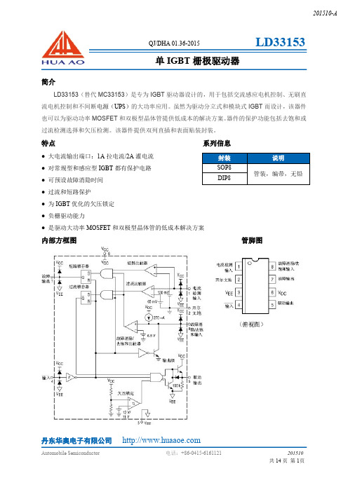
丹东华奥电子有限公司简介LD33153(替代MC33153)是专为IGBT 驱动器设计的,用于包括交流感应电机控制、无刷直流电机控制和不间断电源(UPS )的大功率应用。
虽然为驱动分立式和模块式IGBT 而设计,该器件也可以为驱动功率MOSFET 和双极型晶体管提供低成本的解决方案。
器件的保护功能包括去饱和或过流检测选择和欠压检测。
该器件提供双列直插和表面贴装封装。
特点系列信息●大电流输出端口:1A 拉电流/2A 灌电流●对常规型和感应型IGBT 都有保护电路●可预设故障消隐时间●过流和短路保护●为IGBT 优化的欠压锁定●负栅驱动能力●是驱动大功率MOSFET 和双极型晶体管的低成本解决方案内部方框图管脚图封装说明SOP8管装,编带,无铅DIP8单IGBT 栅极驱动器丹东华奥电子有限公司最大额定值电参数(V CC =15V ,V EE =0V ,开尔文地接至V EE ,T A =25℃,除非另外说明)参数缩写数值单位电源电压V CC 至V EE开尔文地至V EE V CC -V EE K GND -V EE2020V 逻辑输入V IN V EE -0.3至V CC V 电流检测输入V S -0.3至V CC V 消隐/去饱和输入V BD -0.3至V CCV 栅极驱动输入拉电流灌电流二极管箝位电流I O1.02.01.0A故障输出拉电流灌电流I FO 2510mA功耗和热特性SOP8封装最大功耗@Ta=50°C 热阻,结至环境DIP8封装最大功耗@Ta=50°C 热阻,结至环境PD R θJA PD R θJA 0.561801.0100W °C/W W °C/W 工作结温T J 150℃工作环境温度范围T A -40~+105℃储存温度范围T stg-65~+150℃参数缩写最小值典型值最大值单位逻辑输入输入门限电压高电平状态(逻辑1)低电平状态(逻辑0)V IH V IL 1.22.72.33.2V 输入电流高电平状态(V IH =3.0V )低电平状态(V IL =1.2V )I IH I IL13050500100µA驱动输出输出电压低电平状态(I Sink =1.0A )高电平状态(I Source =500mA )V OL V OH 12.02.013.9 2.5V 输出下拉电阻R PD100200k Ω电参数续(V CC=15V,V EE=0V,开尔文地接至V EE地,T A=25℃,除非另外说明)参数缩写最小值典型值最大值单位故障输出输出电压低电平状态(I Sink=5.0A)高电平状态(I Source=20mA)V FLV FH12.00.213.31.0V开关特性传输延迟(50%输入至50%输出,C L=1.0nF)逻辑输入至驱动输出上升逻辑输入至驱动输出下降T PLH(in/out)T PHL(in/out)80120300300ns驱动输出上升时间(10%至90%,C L=1.0nF)t r1755ns 驱动输出下降时间(90%至10%,C L=1.0nF)t f1755ns传输延迟电流检测输入至驱动输出故障消隐/去饱和输入至驱动输出t p(OC)t p(FLT)0.30.31.01.0µsUVLO起动电压V CC start11.31212.6V 禁用电压V CC dis10.41111.7V 比较器过流门限电压(V pin8>7.0V)V SOC506580mV 短路门限电压(V pin8>7.0V)V SSC100130160mV 故障销隐/去饱和门限(V pin1>100mV)V th(FLT) 6.0 6.57.0V 电流检测输入电流(V SI=0V)I SI-1.4-10µA 故障销隐/去饱和输入电流源(V pin8=0V,V pin4=0V)I chg-200-270-300µA 放电电流(V pin8=15V,V pin4=5.0V)I dschg 1.0 2.5mA 器件整体电源电流待机(V pin4=V CC,输出开路)工作(C L=1.0nF,f=20kHz)I CC7.27.91420mA丹东华奥电子有限公司图1.输入电流与输入电压关系曲线图2.输出电压与输入电压关系曲线图3.输入门限电压与温度关系曲线图4.输入门限电压与电源电压关系曲线图5.驱动输出低电平电压与温度关系曲线图6.驱动输出低电平电压与灌电流关系曲线丹东华奥电子有限公司图7.驱动输出高电平电压与温度关系曲线图8.驱动输出高电平电压与拉电流关系曲线图9.驱动输出电压与电流检测输入电压关系曲线图10.故障输出电压与电流检测输入电压关系曲线图11.过流保护门限电压与温度关系曲线图12.过流保护门限电压与电源电压关系曲线丹东华奥电子有限公司图13.短路比较器门限电压与温度关系曲线图14.短路比较器门限电压与电源电压关系曲线图15.电流检测输入电流与电压关系曲线图16.驱动输出电压与故障消隐/去饱和输入电压关系曲线图17.故障消隐/去饱和比较器门限电压与温度关系曲线图18.故障消隐/去饱和比较器门限电压与电源电压关系曲线丹东华奥电子有限公司图19.故障消隐/去饱和电流源与温度关系曲线图20.故障消隐/去饱和电流源与电源电压关系曲线图21.故障消隐/去饱和电流源与输入电压关系曲线图22.故障消隐/去饱和放电电流与输入电压关系曲线图23.故障输出低电平电压与灌电流关系曲线图24.故障输出高电平电压与拉电流关系曲线丹东华奥电子有限公司图25.驱动输出电压与电源电压关系曲线图26.UVLO与温度关系曲线图27.电源电流与电源电压关系曲线图28.电源电流与温度关系曲线图29.电源电流与输入频率关系曲线丹东华奥电子有限公司功能描述栅极驱动开关时间控制(管脚Pin5)栅极驱动的IGBT设计特点主要是优化开关功能特性。
HR9110 玩具单通道直流电机驱动器说明书

描述HR9110是应用于直流电机方案的单通道H桥驱动器芯片。
HR9110的H桥驱动部分采用低导通电阻的PMOS和NMOS功率管。
低导通电阻保证芯片低的功率损耗,使得芯片安全工作更长时间。
此外HR9110拥有低待机电流、低静态工作电流。
这些性能使能HR9110易用于玩具方案。
HR9110内部含有过温关断保护。
当负载电机是低阻抗的,或者输出端短路,这样使能HR9110的输出电流急剧上升,同时内部温度也急剧上升。
当芯片温度超过最大温度阈值(典型150℃),HR9110会关断所有的输出,防止潜在安全隐患。
只有当确认了芯片回归到安全的工作温度,内置温度迟滞电流才重新控制驱动电路。
应用锂电池直流电机驱动玩具机器人控制型号选择Part Number Package HR9110S SOP8 HR9110D DIP8特点●内置PMOS、NMOS的单通道H桥驱动器●四种驱动功能:正传、反转、停转和刹车功能●低RDS(ON)电阻(0.3Ω),连续输出电流1.2A●低待机电流(0.01uA)和低静态工作电流(0.2mA)●低工作电压●宽电压供电,1.8V-6.8V●内置过温关断保护电路●符合RoHS标准封装形式SOP8DIP8功能模块示意图电路工作极限at Ta=25°CParameter Symbol Conditions Ratings UnitLogic Supply Voltage VCC 5.5VLoad Supply Voltage VM 6.8VLogic Input voltage V IN VCC VOutput Current I OUT±1.2APeak Out Current Iop3A Operating Ambient Temperature T A Range S-20to85°C Maximum Junction T J(max)150°CStorage Temperature T stg-55to150°C推荐工作条件at Ta=25°CMin NOM Max Unit Logic Supply Voltage Range VCC 1.8-5VLoad Supply Voltage Range VM 1.8-6VLogic Input Voltage Range VIN0-VCC V Continuous RMS or DC output current per bridge IOUT-1200+1200mA电特性at Ta=25°C,VCC=3V,VM=3V,RL=15Ω,unless otherwise noted。
力士乐 IndraDrive 伺服控制器功率单元 HCS01 使用说明书
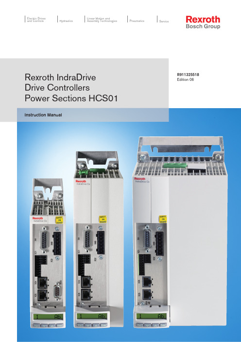
Instruction ManualElectric Drives and ControlsPneumatics ServiceLinear Motion andAssembly TechnologiesHydraulicsRexroth IndraDrive Drive ControllersPower Sections HCS01R911325518Edition 06Rexroth IndraDrive Drive Controllers Power Sections HCS01Instruction ManualDOK-INDRV*-HCS01*UL***-IB06-EN-PRS-49e64cb2ef966abc0a6846a001598e31-8-en-US-2EditionRelease Date Notes DOK-INDRV*-HCS01*UL***-IB01-EN-P 09/2009First edition DOK-INDRV*-HCS01*UL***-IB02-EN-P 07/2010Corrected edition DOK-INDRV*-HCS01*UL***-IB03-EN-P 05/2011Corrected edition DOK-INDRV*-HCS01*UL***-IB04-EN-P 01/2012Corrected edition DOK-INDRV*-HCS01*UL***-IB05-EN-P 05/2012Corrected edition DOK-INDRV*-HCS01*UL***-IB06-EN-P05/2014Corrected editionPurpose of DocumentationThis documentation provides information on the installation and operation of the described products, by persons trained and qualified to work with electri‐cal installations.Copyright© Bosch Rexroth AG 2014This document, as well as the data, specifications and other information set forth in it, are the exclusive property of Bosch Rexroth AG. It may not be re‐produced or given to third parties without its consent.LiabilityThe specified data is intended for product description purposes only and shall not be deemed to be a guaranteed characteristic unless expressly stipulated in the contract. All rights are reserved with respect to the content of this docu‐mentation and the availability of the product.Published byBosch Rexroth AGBgm.-Dr.-Nebel-Str. 2 ■ 97816 Lohr a. Main, Germany Phone +49 9352 18 0 ■ Fax +49 9352 18 8400/DC-IA/EDY4 (CR)TitleType of Documentation Document Typecode Internal File ReferenceRecord of RevisionBosch Rexroth AGDOK-INDRV*-HCS01*UL***-IB06-EN-PRexroth IndraDrive Drive Controllers Power Sections HCS01Table of ContentsPage1Important Notes (3)1.1 Safety Instructions.................................................................................................................................. 31.1.1 General Information............................................................................................................................. 31.1.2 Protection Against Contact with Electrical Parts and Housings........................................................... 41.1.3 Battery Safety...................................................................................................................................... 51.2Appropriate Use (6)2Ratings and Dimensions (7)2.1 Data........................................................................................................................................................ 72.2Dimensional Drawings (11)3Documentations (15)3.1Motors (15)4Instructions for Use (17)4.1 Overcurrent Protection.......................................................................................................................... 174.2 Connection............................................................................................................................................ 184.2.1 Connection Diagram.......................................................................................................................... 184.2.2Connection Points (19)5 Service and Support .................................................................................................... 21Index . (23)DOK-INDRV*-HCS01*UL***-IB06-EN-PRexroth IndraDrive Drive Controllers Power Sections HCS01Bosch Rexroth AG I/25Table of ContentsBosch Rexroth AG DOK-INDRV*-HCS01*UL***-IB06-EN-P II/25Rexroth IndraDrive Drive Controllers Power Sections HCS011Important Notes1.1Safety Instructions1.1.1General Information●Do not attempt to install and operate the components of the electric drive and control system without first reading all documentation provided with the product. Read and understand these safety instructions and all user documentation prior to working with these components. If you do not have the user documentation for the components, contact your re‐sponsible Rexroth sales partner. Ask for these documents to be sent im‐mediately to the person or persons responsible for the safe operation of the components.●If the supplied documents contain some information you do not under‐stand, it is absolutely necessary that you ask Rexroth for explanation before you start working at or with the components.●If the component is resold, rented and/or passed on to others in any oth‐er form, these safety instructions must be delivered with the component in the official language of the user's country.●Only qualified persons may work with components of the electric drive and control system or within its proximity.In terms of this Instruction Manual, qualified persons are those persons who are familiar with the installation, mounting, commissioning and op‐eration of the components of the electric drive and control system, as well as with the hazards this implies, and who possess the qualifications their work requires. To comply with these qualifications, it is necessary,among other things,–to be trained, instructed or authorized to switch electric circuits and components safely on and off, to ground them and to mark them,–to be trained or instructed to maintain and use adequate safety equipment,–to attend a course of instruction in first aid.●The technical data, connection and installation conditions of the compo‐nents are specified in the respective application documentations and must be followed at all times.●If the components take the form of hardware, then they must remain in their original state, in other words, no structural changes are permitted.It is not permitted to decompile software components or alter source co‐des.●Do not mount damaged or faulty components or use them in operation.●Only use accessories and spare parts approved by Rexroth.●Follow the safety regulations and requirements of the country in which the electric components of the electric drive and control system are op‐erated.●Proper and correct transport, storage, mounting and installation, as well as care in operation and maintenance, are prerequisites for optimal and safe operation of the component.Improper use of these components, failure to follow the safety instructions in this document or tampering with the product, including disabling of safety de‐vices, could result in property damage, injury, electric shock or even death.DOK-INDRV*-HCS01*UL***-IB06-EN-PRexroth IndraDrive Drive Controllers Power Sections HCS01Bosch Rexroth AG 3/25Important Notes1.1.2Protection Against Contact with Electrical Parts and HousingsThis section concerns components of the electric drive and con‐trol system with voltages of more than 50 volts .Contact with parts conducting voltages above 50 volts can cause personal danger and electric shock. When operating components of the electric drive and control system, it is unavoidable that some parts of these components conduct dangerous voltage.High electrical voltage! Danger to life, risk of injury by electric shock or seri‐ous injury!●Only qualified persons are allowed to operate, maintain and/or repair the components of the electric drive and control system.●Follow the general installation and safety regulations when working on power installations.●Before switching on, the equipment grounding conductor must have been permanently connected to all electric components in accordance with the connection diagram.●Even for brief measurements or tests, operation is only allowed if the equipment grounding conductor has been permanently connected to the points of the components provided for this purpose.●Before accessing electrical parts with voltage potentials higher than 50 V, you must disconnect electric components from the mains or from the power supply unit. Secure the electric component from reconnec‐tion.●With electric components, observe the following aspects:Always wait 30 minutes after switching off power to allow live capacitors to discharge before accessing an electric component. Measure the elec‐trical voltage of live parts before beginning to work to make sure that the equipment is safe to touch.●Install the covers and guards provided for this purpose before switching on.●Never touch electrical connection points of the components while power is turned on.●Do not remove or plug in connectors when the component has been powered.●Under specific conditions, electric drive systems can be operated at mains protected by residual-current-operated circuit-breakers sensitive to universal current (RCDs/RCMs).●Secure built-in devices from penetrating foreign objects and water, as well as from direct contact, by providing an external housing, for exam‐ple a control cabinet.High housing voltage and high leakage current! Danger to life, risk of injury by electric shock!●Before switching on and before commissioning, ground or connect the components of the electric drive and control system to the equipment grounding conductor at the grounding points.Bosch Rexroth AGDOK-INDRV*-HCS01*UL***-IB06-EN-PRexroth IndraDrive Drive Controllers Power Sections HCS014/25Important Notes●Connect the equipment grounding conductor of the components of the electric drive and control system permanently to the main power supply at all times. The leakage current is greater than 3.5 mA.●Establish an equipment grounding connection with a minimum cross section according to the table below. With an outer conductor cross sec‐tion smaller than 10 mm 2 (8 AWG), the alternative connection of two equipment grounding conductors is allowed, each having the same cross section as the outer conductors.Cross section outer con‐ductorMinimum cross section equipment grounding conductorLeakage current ≥ 3.5 mA1 equipment groundingconductor2 equipment groundingconductors 1.5 mm 2 (16 AWG)10 mm 2 (8 AWG)2 × 1.5 mm 2 (16 AWG)2.5 mm 2 (14 AWG) 2 × 2.5 mm 2 (14 AWG)4 mm 2 (12 AWG) 2 × 4 mm 2 (12 AWG)6 mm 2 (10 AWG) 2 × 6 mm 2 (10 AWG)10 mm 2 (8 AWG)-16 mm 2 (6 AWG)16 mm 2 (6 AWG)-25 mm 2 (4 AWG)-35 mm 2 (2 AWG)-50 mm 2 (1/0 AWG)25 mm 2 (4 AWG)-70 mm 2 (2/0 AWG)35 mm 2 (2 AWG)-.........Tab. 1-1:Minimum Cross Section of the Equipment Grounding Connection1.1.3 Battery SafetyBatteries consist of active chemicals in a solid housing. Therefore, improper handling can cause injury or property damage.Risk of injury by improper handling!●Do not attempt to reactivate low batteries by heating or other methods (risk of explosion and cauterization).●Do not attempt to recharge the batteries as this may cause leakage or explosion.●Do not throw batteries into open flames.●Do not dismantle batteries.●When replacing the battery/batteries, do not damage the electrical parts installed in the devices.●Only use the battery types specified for the product.DOK-INDRV*-HCS01*UL***-IB06-EN-PRexroth IndraDrive Drive Controllers Power Sections HCS01Bosch Rexroth AG 5/25Important NotesEnvironmental protection and disposal! The batteries contained inthe product are considered dangerous goods during land, air, andsea transport (risk of explosion) in the sense of the legal regula‐tions. Dispose of used batteries separately from other waste. Ob‐serve the national regulations of your country.1.2 Appropriate UseThis product may only be used for the mentioned applications under thespecified application, ambient and operating conditions.This product is exclusively intended for use in machines and systems in anindustrial environment. This is to be understood as applications according toIEC 60204-1 "Safety of machinery, Electric equipment of machines" andNFPA 79 "Electrical Standard for Industrial Machinery".Components of the Rexroth IndraDrive Cs system are products ofcategory C3(with limited availability) according to IEC 61800‑3.To ensure that this category (limit values) is maintained, suitableline filters must be used in the drive system.These components are not provided for use in a public low-volt‐age network supplying residential areas with power. If these com‐ponents are used in such a public network, high-frequency inter‐ference is to be expected. This can require additional measuresof radio interference suppression.Bosch Rexroth AG DOK-INDRV*-HCS01*UL***-IB06-EN-PRexroth IndraDrive Drive Controllers Power Sections HCS01 6/25Important Notes2Ratings and Dimensions2.1DataUL Ratings and DimensionsDescriptionSymbolUnitHCS01.1E -W0003-_-02HCS01.1E -W0006-_-02HCS01.1E -W0009-_-02HCS01.1E -W0013-_-02HCS01.1E -W0018-_-02Listing in accordance with UL standardUL 508C Listing in accordance with CSA standard C22.2 No. 14-10UL files E134201Pollution degree2Ambient temperature with nominal dataT amax °C 40Ambient temperature with reduced nominal data T amax_red°C 55Massm kg 0,721,70Device height 1)H mm 215268Device depth 2)T mm 196Device width 3)B mm 5070Minimum distance on the top of the device 4)d top mm 90Minimum distance on the bottom of the device 5)d bot mm 90Horizontal spacing on the device 6)d hor mm 10Rated control voltage input 7)U N3V 24 ± 20%Rated power consumption control voltage input at U N38)P N3W 272834Short circuit current rating SCCR A rms 42000Rated input voltage, power 9)U LN_nennV 1 or 3 x AC 110 (230)Tolerance U LN %± 10Mains frequencyf LNHz 50...60Tolerance input frequency Hz± 2Rated input currentI LNA1.8 or 0.62.8 or 1.2 5.0 or 2.38.3 or 4.512.8 or 9.6Branch circuit protection fuse 10)2.5 or 1.03.5 or 2.07.0 or 3.012.0 or 5.017.5 or15.0Last modification: 2013-12-12DOK-INDRV*-HCS01*UL***-IB06-EN-PRexroth IndraDrive Drive Controllers Power Sections HCS01Bosch Rexroth AG 7/25Ratings and DimensionsDescriptionSymbol UnitHCS01.1E -W0003-_-02HCS01.1E -W0006-_-02HCS01.1E -W0009-_-02HCS01.1E -W0013-_-02HCS01.1E -W0018-_-02Required wire size in accordancewith NFPA 79 and UL 508 A (in‐ternal wiring);11)A LN AWGAWG 14Field wiring material (material;conductor temperature; class)Cu; 60/75 °C; 1Output voltage U out V 3 x AC 0 (230)Output currentI out A 1,12,03,04,57,6Output frequency range 12)f out Hz 0...1600Power dissipation at continuous current and continuous DC bus power respectively 13)P Diss_contW8,0010,0012,0020,0070,00Last modification: 2013-12-121) 2) 3)Housing dimension; see also related dimensional drawing 4) 5) 6)See fig. "Air Intake and Air Outlet at Device"7)Observe supply voltage for motor holding brakes8)HMS, HMD, HCS: Plus motor holding brake and control sec‐tion; HCS01: Incl. control section, plus safety option; KCU:Max. power consumption from 24V supply; KSM: Incl. motor holding brake (if available), plus power consumption of exter‐nally connected inputs/outputs, plus safety option; KMS: Plus motor holding brake, plus power consumption of externally connected inputs/outputs, plus safety option9)Mains input L1, L2, L3 (for HMV and HCS only); For use on a solidly grounded wye source only.10)Use listed AC input line fuses (class J; 600 V AC). Suitable for use on a circuit capable of delivering not more than 42000 rms symmetrical amperes, 500 Volts maximum (HMV and HCS04.2480 Volts maximum). If using inverse-time circuit breakers or type E combination motor controllers instead of recommended fuses, see UL 508C section 45.8.2.11)Copper wire; PVC-insulation (conductor temperature 90 °C;T a ≤ 40 °C) in accordance with NFPA 79 chapter 12 and UL 508A chapter 2812)Depending on switching frequency which was set in parameter P‑0‑000113)Plus dissipation of braking resistor and control sectionTab. 2-1:HCS - UL Ratings and DimensionsUL Ratings and DimensionsDescriptionSymbolUnitHCS01.1E -W0005-_-03HCS01.1E -W0008-_-03HCS01.1E -W0018-_-03HCS01.1E -W0028-_-03HCS01.1E -W0054-_-03Listing in accordance with UL standardUL 508C Listing in accordance with CSA standardC22.2 No. 14-10Last modification: 2013-12-12Bosch Rexroth AGDOK-INDRV*-HCS01*UL***-IB06-EN-PRexroth IndraDrive Drive Controllers Power Sections HCS018/25Ratings and DimensionsDescription Symbol UnitHCS01.1E -W0005-_-03HCS01.1E -W0008-_-03HCS01.1E -W0018-_-03HCS01.1E -W0028-_-03HCS01.1E -W0054-_-03UL files E134201Pollution degree2Ambient temperature with nominaldataT amax °C 40Ambient temperature with reduced nominal data T amax_red°C 55Massm kg 0,721,704,22Device height 1)H mm 215268Device depth 2)T mm 196Device width 3)B mm 5070130Minimum distance on the top of the device 4)d top mm 90Minimum distance on the bottom of the device 5)d bot mm 90Horizontal spacing on the device 6)d hor mm 10Rated control voltage input 7)U N3V 24 ± 20%Rated power consumption control voltage input at U N38)P N3W 27283445Short circuit current rating SCCR A rms 42000Rated input voltage, power 9)U LN_nennV 3 x AC 200 (500)Tolerance U LN %± 10Mains frequencyf LNHz 50...60Tolerance input frequency Hz± 2Rated input currentI LNA1,52,55,010,028,0Branch circuit protection fuse 10)24101530Required wire size in accordance with NFPA 79 and UL 508 A (in‐ternal wiring);11)A LNAWGAWG 14AWG 10Field wiring material (material;conductor temperature; class)Cu; 60/75 °C; 1Output voltage U out V 3 x AC 0 (500)Output currentI out A 1,72,77,611,521,0Output frequency range 12)f out Hz 0...1600Power dissipation at continuous current and continuous DC bus power respectively 13)P Diss_contW37,0046,0080,00120,00400,00Last modification: 2013-12-121) 2) 3)Housing dimension; see also related dimensional drawingRexroth IndraDrive Drive Controllers Power Sections HCS01Ratings and Dimensions4) 5) 6)See fig. "Air Intake and Air Outlet at Device"7)Observe supply voltage for motor holding brakes8)HMS, HMD, HCS: Plus motor holding brake and control sec‐tion; HCS01: Incl. control section, plus safety option; KCU:Max. power consumption from 24V supply; KSM: Incl. motor holding brake (if available), plus power consumption of exter‐nally connected inputs/outputs, plus safety option; KMS: Plus motor holding brake, plus power consumption of externally connected inputs/outputs, plus safety option9)Mains input L1, L2, L3 (for HMV and HCS only); For use on a solidly grounded wye source only.10)Use listed AC input line fuses (class J; 600 V AC). Suitable for use on a circuit capable of delivering not more than 42000 rms symmetrical amperes, 500 Volts maximum (HMV and HCS04.2480 Volts maximum). If using inverse-time circuit breakers or type E combination motor controllers instead of recommended fuses, see UL 508C section 45.8.2.11)Copper wire; PVC-insulation (conductor temperature 90 °C;T a ≤ 40 °C) in accordance with NFPA 79 chapter 12 and UL 508A chapter 2812)Depending on switching frequency which was set in parameter P‑0‑000113)Plus dissipation of braking resistor and control sectionTab. 2-2:HCS - UL Ratings and DimensionsDistancesA Air intakeB Air outletC Mounting surface in control cabinet d top Distance top d bot Distance bottom d horDistance horizontalFig. 2-1:Air Intake and Air Outlet at DeviceRexroth IndraDrive Drive Controllers Power Sections HCS01Ratings and Dimensions2.2 Dimensional DrawingsHCS01.1E-W0003/5/6/8/9/13Standard mounting:A Minimum mounting clearanceB Boring dimensions CMounting surfaceFig. 2-2:Dimensional Drawing HCS01.1E-W0003/5/6/8/9/13 (Standard Mount‐ing)Left-hand or right-hand mounting:A Minimum mounting clearanceB Boring dimensions CMounting surfaceFig. 2-3:Dimensional Drawing HCS01.1E-W0003/5/6/8/9/13 (Left-Hand or Right-Hand Mounting)Rexroth IndraDrive Drive Controllers Power Sections HCS01Ratings and DimensionsHCS01.1E-W0018/28Standard mounting:A Minimum mounting clearanceB Boring dimensions CMounting surfaceFig. 2-4:Dimensional Drawing HCS01.1E-W0018/28 (Standard Mounting)Left-hand or right-hand mounting:A Minimum mounting clearanceB Boring dimensions CMounting surfaceFig. 2-5:Dimensional Drawing HCS01.1E-W0018/28 (Left-Hand or Right-Hand Mounting)Rexroth IndraDrive Drive Controllers Power Sections HCS01Ratings and DimensionsHCS01.1E-W0054Standard mounting:A Minimum mounting clearanceB Boring dimensions CMounting surfaceFig. 2-6:Dimensional Drawing HCS01.1E-W0054 (Standard Mounting)Left-hand or right-hand mounting:A Minimum mounting clearanceB Boring dimensions CMounting surfaceFig. 2-7:Dimensional Drawing HCS01.1E-W0054 (Left-Hand or Right-Hand Mounting)Rexroth IndraDrive Drive Controllers Power Sections HCS01Ratings and DimensionsRexroth IndraDrive Drive Controllers Power Sections HCS01Rexroth IndraDrive Drive Controllers Power Sections HCS01Documentations 3 Documentations3.1 Motors1)In the document typecodes, "xx" is a wild card for the currentedition of the documentation (example: PR01 is the first editionof a Project Planning Manual)Tab. 3-1:Documentations – MotorsRexroth IndraDrive Drive Controllers Power Sections HCS01Rexroth IndraDrive Drive Controllers Power Sections HCS01Instructions for Use 4 Instructions for Use4.1 Overcurrent ProtectionProtect the components against overcurrent:●Branch circuit protection has to be provided externally●Dimension the branch circuit protection according to the data "Branchcircuit protection fuse" (see Ratings and Dimensions)4.2Connection4.2.1Connection Diagram*Optional**ECONOMY = sercos III; BASIC = Multi-Ethernet; ADVANCED = sercos III cross communication (CCD)***Only available at HCS01.1E-W00**-A-0*-A-CC (ADVANCED)devicesX6.1, X6.2T1 and T2 are not available at MSM motors. For proper func‐tion of the motor thermal management connect the motor ther‐mal sensor as described in the wiring diagram. Otherwise mo‐tor overtemperature sensing is not provided by the drive. For Rexroth motors with data memory in the motor encoder, such as MSK, the motor overload protection level is set automatical‐ly while connecting the motor to the drive. There is no adjust‐ment necessary. Otherwise refer to the Rexroth firmware docu‐mentation.X31No standard assignment preset; make the assignment bymeans of firmware documentation (see Functional Description,index entry "Digital inputs/outputs")X47.1, X47.2For the "ready for operation" message of the device, the Bb re‐lay contact (X47.1, X47.2) must be wiredX47.3…6Module bus only available at HCS01.1E-W00xx-x-03 devices X77DC bus connection (L+, L-) only available atHCS01.1E‑W00xx‑x‑03 devicesFig. 4-1:Connection DiagramRexroth IndraDrive Drive Controllers Power Sections HCS01Instructions for Use4.2.2 Connection PointsSymbols used to describe the connection pointsScrew ter‐minal blockSpring ter‐minalD-SubRJ-45IndustrialMini I/OThread Max. con‐nectioncross sec‐tionStrippedlengthMax. tighten‐ing torqueTab. 4-1:SymbolsConnection point HCS01mm2 (AWG)mm NmA, B, C M5-5 X3 A 1)2,5 (14)80,6B 2)6,0 (10)100,8C 3)10,0 (8)141,7X4A, B, C---X5A2,5 (14)80,6B6,0 (10)100,8C10,0 (8)141,7 X6A, B, C1,5 (16)10-X8A, B, C---X9A, B, C- 5)---X13A, B, C2,5 (14)10-X22 P2, X23 P1A, B, C---X24 P2, X25 P1A, B, C---X26A, B, C---X30A, B, C---X31A, B, C1,5 (16)10-X32A, B, C1,5 (16)10-X37A, B, C1,5 (16)10-X38A, B, C1,5 (16)10-X41A, B, C1,5 (16)10-X42, X43A, B, C---X47A, B, C1,5 (16)10-X49A, B, C1,5 (16)8-DOK-INDRV*-HCS01*UL***-IB06-EN-PRexroth IndraDrive Drive Controllers Power Sections HCS01Bosch Rexroth AG19/25Instructions for UseConnection point HCS01mm2 (AWG)mm Nm X61A, B, C---X77 D 4) 6 (8)15-1)A: HCS01.1E-W0003…W0013-x-02, -W0005-x-03,‑W0008‑x‑032)B: HCS01.1E-W0018-x-02, -W0018-x-03, -W0028-x-033)C: HCS01.1E-W0054-x-034)D: HCS01.1E-W00xx-x-035)Connector available at braking resistorTab. 4-2:Connection PointsBosch Rexroth AG DOK-INDRV*-HCS01*UL***-IB06-EN-PRexroth IndraDrive Drive Controllers Power Sections HCS01 20/25Instructions for Use5 Service and SupportOur worldwide service network provides an optimized and efficient support.Our experts offer you advice and assistance should you have any queries.You can contact us 24/7.Service GermanyOur technology-oriented Competence Center in Lohr, Germany, is responsi‐ble for all your service-related queries for electric drive and controls.Contact the Service Helpdesk & Hotline under:Phone:+49 9352 40 5060Fax:+49 9352 18 4941E-mail:***************************Internet:Additional information on service, repair (e.g. delivery addresses) and training can be found on our internet sites.Service worldwide Outside Germany, please contact your local service office first. For hotline numbers, refer to the sales office addresses on the internet.Preparing informationTo be able to help you more quickly and efficiently, please have the following information ready:●Detailed description of malfunction and circumstances resulting in the malfunction●Type plate name of the affected products, in particular type codes and serial numbers●Your contact data (phone and fax number as well as your email ad‐dress)DOK-INDRV*-HCS01*UL***-IB06-EN-PRexroth IndraDrive Drive Controllers Power Sections HCS01Bosch Rexroth AG 21/25Service and SupportBosch Rexroth AG DOK-INDRV*-HCS01*UL***-IB06-EN-P 22/25Rexroth IndraDrive Drive Controllers Power Sections HCS01IndexAAdditional documentations (15)Ambient conditions (7)Appropriate use (6)C Connection (18)Connection diagram (18)Connection pointsHCS01 (19)DDataHCS01, dimensional drawings (11)HCS01, dimensions (11)Dimensional drawingHCS01.1E-W0003/5/6/8/9/13 (11)HCS01.1E-W0018/28 (12)HCS01.1E-W0054 (13)Dimensional drawingsHCS01 (11)Dimensions (7)HCS01.1E-W0003/5/6/8/9/13 (11)HCS01.1E-W0018/28 (12)HCS01.1E-W0054 (13)Distances (10)DocumentationAdditional documentations (15)Motors (15)Overview (15)Reference documentations (15)HHCS01Dimensional drawings (11)Dimensions (11)Technical data (7)IInstructions for use (17)MMotorDocumentation (15)OOperating conditions (7)Overcurrent protection (17)PPower consumption (7)R Ratings..................................................................7Reference documentations (15)SSafety instructions (3)SupportSee service hotline (21)TTechnical data (7)UUL ratings (7)UseAppropriate (6)Instructions (17)VVoltage load capacity (7)XX3 (19)X4 (19)X5 (19)X6 (19)X8 (19)X9 (19)X13 (19)X22, X23 (19)X24, X25 (19)X26 (19)X30 (19)X31 (19)X32 (19)X37 (19)X38 (19)X41 (19)X42, X43 (19)X47 (19)X49 (19)X61 (19)X77 (19)DOK-INDRV*-HCS01*UL***-IB06-EN-PRexroth IndraDrive Drive Controllers Power Sections HCS01Bosch Rexroth AG23/25Index。
Eaton DC1...E1变频驱动器操作永磁和无刷直流电机说明书
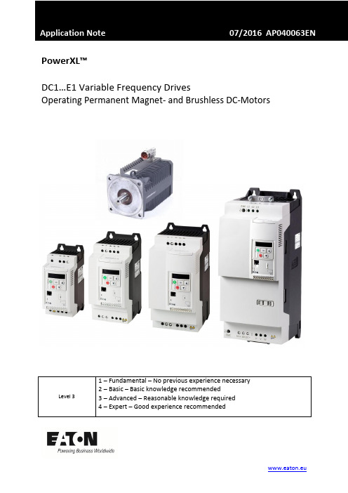
PowerXL™DC1…E1 Variable Frequency DrivesOperating Permanent Magnet- and Brushless DC-MotorsContents1 General (5)2 Selection of the Motor Control Mode (6)2.1 Motor Control Mode (P-60) (6)3 Setting Motor Data (7)3.1 Motor Nom Voltage (P-07) (7)3.2 Motor Nom Current (P-08) (7)3.3 I-CurrentLimit (P-63) (8)3.4 Motor Nom Frequency (P-09) (8)3.5 Motor Nom Speed (P-10) (8)3.6 Switching Frequency (P-17) (9)3.7 Motor Identification (P-61) (9)4 Optimization (11)4.1 Motor performance at low speed (11)4.2 Optimization of the speed controller (11)5 Faults and possible root causes (12)6 Example how to set motor parameters (13)Danger! - Dangerous electrical voltage!∙Disconnect the power supply of the device.∙Ensure that devices cannot be accidentally restarted.∙Verify isolation from the supply.∙Cover or enclose any adjacent live components.∙Follow the engineering instructions (AWA/IL) for the device concerned.∙Only suitably qualified personnel in accordance with EN 50110-1/-2 (VDE 0105 Part 100) may work on this device/system.∙Before installation and before touching the device ensure that you are free of electrostatic charge.∙The functional earth (FE, PES) must be connected to the protective earth (PE) or the potential equalization.The system installer is responsible for implementing this connection.∙Connecting cables and signal lines should be installed so that inductive or capacitive interference does not impair the automatic control functions.∙Suitable safety hardware and software measures should be implemented for the I/O interface so that an open circuit on the signal side does not result in undefined states.∙Deviations of the mains voltage from the rated value must not exceed the tolerance limits given in the specification, otherwise this may cause malfunction and/or dangerous operation.∙Emergency stop devices complying with IEC/EN 60204-1 must be effective in all operating modes. Unlatch-ing of the emergency-stop devices must not cause a restart.∙Devices that are designed for mounting in housings or control cabinets must only be operated and con-trolled after they have been properly installed and with the housing closed.∙Wherever faults may cause injury or material damage, external measures must be implemented to ensurea safe operating state in the event of a fault or malfunction (e.g. by means of separate limit switches, me-chanical interlocks etc.).∙Frequency inverters may have hot surfaces during and immediately after operation.∙Removal of the required covers, improper installation or incorrect operation of motor or frequency invert-er may destroy the device and may lead to serious injury or damage.∙The applicable national safety regulations and accident prevention recommendations must be applied to all work carried on live frequency inverters.∙The electrical installation must be carried out in accordance with the relevant electrical regulations (e. g.with regard to cable cross sections, fuses, PE).∙Transport, installation, commissioning and maintenance work must be carried out only by qualified per-sonnel (IEC 60364, HD 384 and national occupational safety regulations).∙Installations containing frequency inverters must be provided with additional monitoring and protective devices in accordance with the applicable safety regulations. Modifications to the frequency inverters us-ing the operating software are permitted.∙All covers and doors must be kept closed during operation.∙To reduce the hazards for people or equipment, the user must include in the machine design measures that restrict the consequences of a malfunction or failure of the frequency inverter (increased motor speed or sudden standstill of motor). These measures include: – Other independent devices for monitoring safety related variables (speed, travel, end positions etc.).•Electrical or non-electrical system-wide measures (electrical or mechanical interlocks).•Never touch live parts or cable connections of the frequency inverter after it has been discon-nected from the power supply. Due to the charge in the capacitors, these parts may still be aliveafter disconnection. Consider appropriate warning signs.DisclaimerThe information, recommendations, descriptions, and safety notations in this document are based on Eaton’s experience and judgment and may not cover all contingencies. If further information is required, an Eaton sales office should be consulted. Sale of the product shown in this literature is subject to the terms and conditions outlined in the applicable Terms and Conditions for Sale of Eaton or other contractual agreement between Eaton and the purchaser. THERE ARE NO UNDERSTAND-INGS, AGREEMENTS, WARRANTIES, EXPRESSED OR IMPLIED, INCLUDING WARRANTIES OF FITNESS FOR A PARTICULAR PURPOSE OR MERCHANTABILITY, OTHER THAN THOSE SPECIFICALLY SET OUT IN ANY EXISTING CONTRACT BETWEEN THE PARTIES. ANY SUCH CONTRACT STATES THE ENTIRE OBLI-GATION OF EATON. THE CONTENTS OF THIS DOCUMENT SHALL NOT BECOME PART OF OR MODIFY ANY CONTRACT BETWEEN THE PARTIES. As far as applicable mandatory law allows so, in no event will Eaton be responsible to the purchaser or user in contract, in tort (including negligence), strict liability, or otherwise for any special, indirect, incidental, or consequential damage or loss whatsoev-er, including but not limited to damage or loss of use of equipment, plant or power system, cost of capital, loss of power, additional expenses in the use of existing power facilities, or claims against the purchaser or user by its customers resulting from the use of the information, recommendations, and descriptions contained herein. The information contained in this manual is subject to change without notice.1GeneralDevices of the series PowerXL™ DC1…E1 are variable frequency drives for the supply of three phase motors. By default they are configured in a way, that induction motors of the respective power class can be supplied without changing the settings. The connection of permanent magnet motors (PM Motors) and Brushless DC Motors (BLDC Motors) is also possible, but requires the selection of the respective Motor Control Mode and an adaptation of some parameters.Devices of the series DC1…E1control PM motors and BLDC motors in …open loop“ without feedback by a speed sensor. Compared to induction motors they are mainly used because of the smaller frame size and an increased efficiency. The applications are similar to the ones with induction motors, but with increased dynamics. The series DC1…E1 is NOT intended to be used in servo applications with PM- and BLDC motors and therefore DC1…E1 doesn’t have functionalities like positioning …..In this Application Note the following aspects are covered:∙Selection of the motor control mode∙Adaptation to the connected motor∙Optimization of the application∙Trouble shooting∙Example: PM-Motor settingsSome required parameters are inside level 3. This level has to be activated by prompting the pass-word into P-14 (Password). The password is 201 by default.See also: AP040052EN “Access to Parameter Level 2 + 3 – Parameter lock –Load Default”.This Application Note presumes that the user is familiar with vector control of induction motors and the setting of the respective parameters, as well as with the optimization of speed control loops.2Selection of the Motor Control ModePM motors and BLDC motors require a different control algorithm compared to induction motors, for which the default settings are intended. A selection is done via parameter P-60.NOTE: The difference between PM motors and BLDC motors is mainly the wave form of the induced voltage (Back EMF). The control modes of DC1…E1 are optimized for that. On the market ther e is no clear differentiation between the two types of motors and sometimes one can find BLDC motors which are named as PM motors or PM motors with a similar induced voltage as a BLDC motor. In case of a bumpy run in the control mode for PM motors (P-60 = 2) sometimes an improvement can be achieved by selecting the control mode for BLDC motors (P-60 = 3).2.1Motor Control Mode (P-60)This parameter adapts the device to the type of the connected motor and determines the way of control. The information given in this Application Note are valid for PM motors and BLDC motors only and refer to the settings P-60 = 2 and 3.Information for the control of induction motors (P-60 = 0 and 1): see Application Note AP040049EN.3Setting Motor DataBefore switching on the motor, the motor data according the name plate or the data sheet have to be prompted and a motor identification run has to be performed.3.1Motor Nom Voltage (P-07)This parameter has to be set to the value of the induced voltage (back EMF) at rated speed. This volt-age is the voltage between two phases. In case the manufacturer states the value between phase and neutral, it has to be multiplied by √3.Inside the documentation of the motor manufacturers one can find the required information in dif-ferent formats.∙as a voltage value ( sometimes called “rated voltage”)∙as a voltage constant (induced voltage at a certain speed, mostly 1000 rpm). In this case the volt-age at the required speed has to be calculated.Example:∙voltage constant = 50 V / 1000 rpm∙required speed = 3000 rpmP-07=50 V1000 rpm∙ 3000 rpm= 150 VeNote: the voltage given by the motor manufacturers can have different meanings:∙The voltage induced at rated speed (Back-EMF). In this case this value has to be prompted.∙The voltage which is present at rated speed and rated torque. This value is higher than the in-duced voltage. It can possibly lead to a situation where the motor takes more current respec-tively runs bumpy. What are the possibilities to determine the right value?o Run motor at rated speed and switch off. Take an oscilloscope and measure the in-duced voltage directly after switch off.3.2Motor Nom Current (P-08)Rated current of the motor. By default, parameter P-08 …Motor Nom Current“ is set to the rated cu r-rent I e of the variable frequency drive. P-08 is also used to set the thermal protection for the motor. In case the rated current of the motor is different to the one of the variable frequency drive, P-08 has to be set accordingly to provide a thermal motor protection.e3.3I-CurrentLimit (P-63)The nominal current of the motor (P-08) can be exceeded for a certain time to provide additional torque during acceleration. In default it is 150 % of the rated current for 60 s within 10 minutes or the equivalent.The maximum value can be set with P-63. This setting has no influence on the motor protection and determines only the max. possible current.This function is of help in cases, where high inertias are accelerated. From experience this can some-times lead to trips because of overcurrent, in cases where the max. current and the hardware trip threshold of the device are too close.3.4Motor Nom Frequency (P-09)Frequency which is necessary for the required speed of the motor. Mostly it can be found as “rated frequency” on the motor name plate or in a data sheet. In case the frequency is not known, it can be calculated out of speed and number of poles p.P-09 [Hz]=n [rpm] ∙p2 ∙60 s/minNOTE: A change of P-09 affects the following parameter settings:3.5Motor Nom Speed (P-10)Motor rated speed in rpm. This is the speed at the frequency set with P-09.NOTE: A change of P-09 “Motor Nom Frequency” will set P-10 to 0!3.6 Switching Frequency (P-17)Switching frequency of the power section. With PM motors and BLDC motors a minimum switching frequency of 16 kHz is recommended. Setting the switching frequency is always a compromise be-tween a smooth run of the motor at higher values and resulting additional losses at the same time. At values above 16 kHz it has to be noted, that DC1…E1 possibly has to be derated and in some cases a device with the next higher rating has to be used.3.7 Motor Identification (P-61)A motor identification run MUST be performe d when using a device of the DC1…E1 series together with a PM motor or a BLDC motor (P-60 = 2 or 3). It sets the parameters automatically, which are necessaryfor an optimal performance. After the motor identification run the drive is ready to be used. Further optimization, see below.The motor identification run determines the values of the following parameters∙ Motor Stator Resistance (P-64)∙ Motor Stator Inductance d-axis (P-65) ∙ Motor Stator Inductance q-axis (P-66)The respective values can also be prompted manually, in case they are available from the motor manufacturer. It is recommended to rely on the motor identification run, because it gives very accu-rate values and ensures optimal performance.A motor identification run is performed during stand still. The internal motor model uses the results for an optimal control of the connected motor.Procedure:∙ Real Time Edit Mode of a DrivesConnect Software, which is possibly connected to the drive, hasto be deactivated. Better: Unplug the connection at the RJ45 jack when performing a motor iden-tification run.∙ DC1…E1 must not be enabled (no START signal) ∙ Select parameter P-62 ∙ Press OK∙ is displayed ∙ Change value to∙ Acknowledge with OK The identification starts automatically, display: resp. Auto-tuning (OLED-display)∙ After the identification the value will automatically be reset to zero. Display: ∙ The device has determined the required parameters.HINT: The motor identification run has ALWAYS to be performed at the device itself. It is NOT possi-ble to activate it through the parameter software DrivesConnect. The motor parameters P-07, P-08and P-09 have to be set before starting the motor identification.4 Optimization4.1 Motor performance at low speedNormally PM motors and BLDC motors can be used in a speed range of 20:1. The series DC1…E1 has a boost function, which increases the torque in the lower range resulting in an improved start behavior and true running in the lower speed range.In case …Motor Control Mode“ P -60 = 2 (PM motors) or P-60 = 3 (BLDC motors), a current, which is injected into the motor, can be set with P-11. The amount of current is calculated as follows:I Boost = 4 ∙ P-11 ∙ P -084.2 Optimization of the speed controllerThe control of PM motors and BLDC motors is based on vector algorithms and the speed loop can be optimized. The factory settings are intended for induction motors. PM motors and BLDC motors al-low higher gains and therefore shorter response times and improved behavior.Parameter P-62 …MSC Gain“ affects the proportional gainof the speed controller as well as the inte-gral one. Changes should be done step by step, while observing their impact to the system behavior. Increasing the value leads to a stronger reaction and consequently to a reduction of the response time. Too high values of P-62 can lead to an instability of the system.5Faults and possible root causesGeneral fault messages and their root causes are described in the user manual for the drives series DC1…E1. The faults listed below are especially related to the use of PM motors and BLDC motors.6Example how to set motor parametersExcerpt from a data sheet of a PM motor manufacturer:Settings of motor parameters:∙P-07 = KE ∙ n N = 64,2 V / 1000 rpm ∙ 3600 r/min = 231 V*∙P-08 = 7.5 A∙P-09 = 240 Hz∙P-10 = 3600 r/minFurther important settings∙Enable menu level 3 (Prompt value defined by P-37 + 100 into P-14. Default: 201)∙The switching frequency (P-17) has to be at least 16 kHz∙Select motor control mode with P-60 (in this example: 2 PM motor with speed regulation) ∙Perform motor identification run with P-61∙Optimize motor performance at start and low speeds (P-11).∙Optimize speed controller, if necessary。
TSDA-C21B直流伺服驱动器用户手册说明书
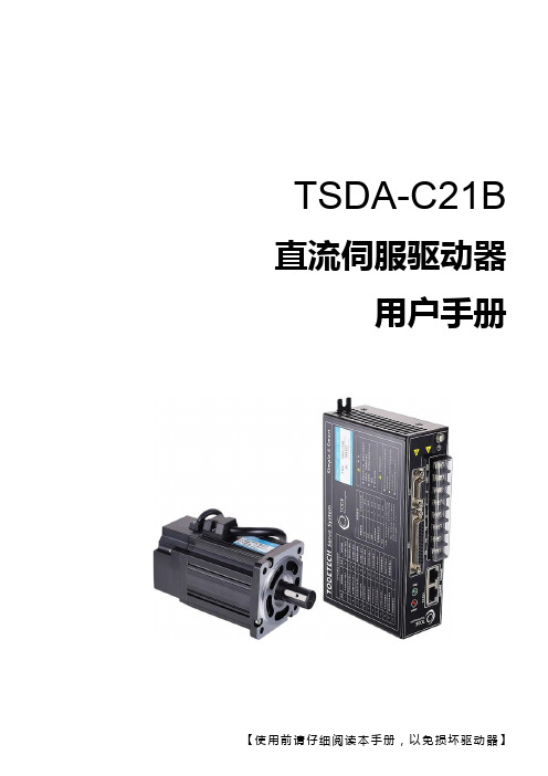
TSDA-C21B 直流伺服驱动器用户手册目录 (1)前言 (2)安全注意事项 (3)概述 (5)一. 基本特性 (5)二. 适用领域 (5)三. 技术指标 (5)四. 接口定义 (6)4.1 电源/电机接口 (6)4.2 编码器接口 (7)4.3 通讯接口 (7)4.4 报警信息查询 (8)4.5 控制接口 (8)五. 控制方式 (9)5.1基本控制 (9)5.2 RS232通讯控制 (10)5.3 CAN通讯控制 (14)5.4 CAN通讯控制应用说明 (21)5.5 CAN通讯控制应用实例 (22)5.6 RS485通讯控制 (25)5.7 RS485通讯控制实例 (28)5.8 IDS调试软件设置实例 (32)六.控制信号典型接线 (34)七.外形安装尺寸 (35)前言本手册阐述了TSDA-C21B低压直流伺服驱动器(5W~1500W范围)的安装、调试、维护、运行等方面。
使用前,请认真阅读本手册,熟知本产品的安全注意事项。
本手册,因产品改进、规格、版本变更等原因,将会适时改动,本公司将不另行通知。
在使用本公司产品时如有任何疑问,请查阅相关说明书或致电联系本公司技术服务部,我们会在最短的时间内满足您的要求。
符号与警示标志:危险:表示该操作错误可能危及人身安全!注意:表示该操作错误可能导致设备损坏!安全注意事项开箱检查缺少零部件和受损的控制器,切勿安装;伺服驱动器必须与之匹配的伺服电机配套使用。
安装安装在不易燃烧的金属架上,防止尘埃、腐蚀性气体、导电物体、液体及易燃物侵入,并保持良好的散热条件;安装时,一定拧紧驱动器的安装螺钉,伺服驱动器和伺服电机应避免震动,禁止承受冲击。
接线请由专业电气工程人员进行接线作业;接线前,请确认输入电源是在切断状态,接线和检查必须在电源切断且驱动器指示灯熄灭后进行,防止电击;对驱动器的接线端子进行插拔时,请确保在驱动器指示灯熄灭后再进行;接地端子PE须通过驱动器左边镙钉可靠接地;请在控制器外部设置急停电路;请勿将电源输入线接到输出U、V、W端子上;请用合适力矩紧固输出端子。
AutomationDirect公司增加同步驱动器组件
AutomationDirect公司增加同步驱动器组件
佚名
【期刊名称】《伺服控制》
【年(卷),期】2015(000)003
【摘要】目前,AutomationDirect公司增加SureMotion动力传动产品,包括
定时皮带轮(或链轮),衬套和同步皮带,允许用户改变速度和转矩,同时连接机械旋转部件。
SureMotionXL定时皮带轮,节距l/5英寸、宽1/4或3/8英寸,并且提供铝制或钢制、有毂或无毂、带光滑孔和固定螺钉。
SureMotionL定时皮
带轮,节距3/8英寸、宽度为l/2或l英寸。
提供铝制或钢制、有毂或无毂、带光滑孔和固定螺钉。
SureMotionL钢制皮带轮适用于锥形锁或QD风格的驱动器,也可以提供钢套管。
【总页数】1页(P5-5)
【正文语种】中文
【中图分类】TH13
【相关文献】
1.AutomationDirect发布IronHorse GSD1系列直流驱动器 [J], ;
2.AutomationDirect公司增加了SureGear伺服减速机 [J], ;
3.AutomationDirect公司推出IronHorse直流驱动器 [J],
4.AutomationDirect公司推出最新的DURApulse系列无传感器矢量交流驱动器[J],
5.公司业绩价值驱动器与关键业绩指数--基于经济增加值的员工激励机制探讨 [J], 张纯
因版权原因,仅展示原文概要,查看原文内容请购买。
Banner Engineering 自集成型,直流驱动的传感器快速启动指南说明书
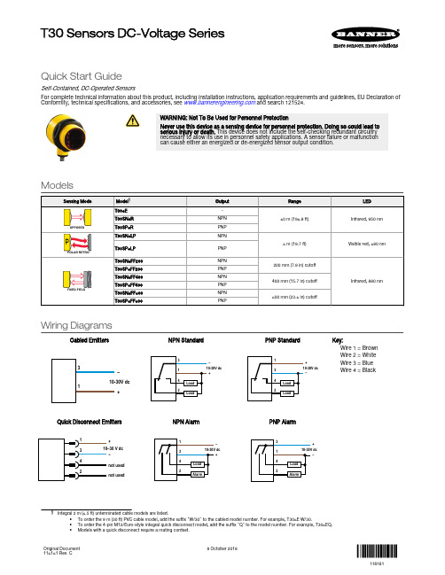
Quick Start GuideSelf-Contained, DC-Operated SensorsFor complete technical information about this product, including installation instructions, application requirements and guidelines, EU Declaration of Conformity, technical specifications, and accessories, see and search 121524.WARNING: Not To Be Used for Personnel ProtectionNever use this device as a sensing device for personnel protection. Doing so could lead toserious injury or death. This device does not include the self-checking redundant circuitrynecessary to allow its use in personnel safety applications. A sensor failure or malfunctioncan cause either an energized or de-energized sensor output condition.ModelsWiring DiagramsCabled Emitters–+NPN Standard–+PNP Standard–+Key:Wire 1 = BrownWire 2 = WhiteWire 3 = BlueWire 4 = BlackQuick Disconnect Emitters+−not usednot usedNPN Alarm–+PNP Alarm–+•To order the 9 m (30 ft) PVC cable model, add the suffix "W/30" to the cabled model number. For example, T306E W/30.•To order the 4-pin M12/Euro-style integral quick disconnect model, add the suffix "Q" to the model number. For example, T306EQ.•Models with a quick disconnect require a mating cordset.T30 Sensors DC-Voltage SeriesOriginal Document116161 Rev. C8 October 2018116161SpecificationsSupply Voltage and Current10 V dc to 30 V dc (10% maximum ripple)Supply current (exclusive of load current):Emitters, Non-Polarized, Retro: 25 mA Receivers: 20 mAPolarized Retroreflective: 30 mA Fixed-Field: 35 mAOutput ConfigurationSPDT solid-state dc switch; NPN or PNP outputs, depending on modelLight Operate: N.O. output conducts when sensor sees its own (or the emitter’s)modulated lightDark Operate: N.C. output conducts when the sensor sees dark; the N.C. output may be wired as a normally open marginal signal alarm output, depending on wiring to power supply Output Rating150 mA maximum eachWhen wired for alarm output, the total load may not exceed 150 mA OFF-state leakage current: < 1 µA at 30 V dcON-state saturation voltage: < 1 V at 10 mA dc; < 1.5 V at 150 mA dcRequired Overcurrent ProtectionWARNING: Electrical connections must be made by qualified personnel in accordance with local and national electrical codes and regulations.Overcurrent protection is required to be provided by end product application per the supplied table.Overcurrent protection may be provided with external fusing or via Current Limiting,Class 2 Power Supply.Supply wiring leads < 24 AWG shall not be spliced.For additional product support, go to .Supply Protection CircuitryProtected against reverse polarity and transient voltages Output Protection CircuitryProtected against output short-circuit, continuous overload, and false pulse on power-upOutput Response TimeOpposed mode: 3 ms ON, 1.5 ms OFFRetro, Fixed-Field and Diffuse:3 ms ON and OFFNote: 100 ms delay on power-up; outputs do not conduct during this timeRepeatabilityOpposed mode: 375 μsRetro, Fixed-Field and Diffuse: 750 μsRepeatability and response are independent of signal strength IndicatorsTwo LEDs (Green and Amber)Green ON steady: power to sensor is ON Green flashing: output is overloadedAmber ON steady: N.O. output is conductingAmber flashing: excess gain marginal (1 to 1.5 times) in light condition ConstructionHousing: PBT polyesterLens: Polycarbonate (opposed-mode) or acrylic Environmental RatingLeakproof design rated NEMA 6P, DIN IP69K Connections2 m (6.5 ft) or 9 m (30 ft) integral PVC cable or Integral 4-pin M12/Euro-style quick disconnectOperating ConditionsTemperature: –40 °C to +70 °C (–40 °F to +158 °F)Humidity: 90% at +50 °C maximum relative humidity (non-condensing)Vibration and Mechanical ShockAll models meet MIL-STD-202F, Method 201A (Vibration: 10 Hz to 60 Hz maximum,0.06 inch (1.52 mm) double amplitude, 10G acceleration) requirements. Method 213B conditions H&I. (Shock: 75G with unit operating; 100G for non-operation)CertificationsBanner Engineering Corp. Limited WarrantyBanner Engineering Corp. warrants its products to be free from defects in material and workmanship for one year following the date of shipment. Banner Engineering Corp. will repair or replace, free of charge,any product of its manufacture which, at the time it is returned to the factory, is found to have been defective during the warranty period. This warranty does not cover damage or liability for misuse, abuse, or the improper application or installation of the Banner product.THIS LIMITED WARRANTY IS EXCLUSIVE AND IN LIEU OF ALL OTHER WARRANTIES WHETHER EXPRESS OR IMPLIED (INCLUDING, WITHOUT LIMITATION, ANY WARRANTY OF MERCHANTABILITY OR FITNESS FOR A PARTICULAR PURPOSE), AND WHETHER ARISING UNDER COURSE OF PERFORMANCE, COURSE OF DEALING OR TRADE USAGE.This Warranty is exclusive and limited to repair or, at the discretion of Banner Engineering Corp., replacement. IN NO EVENT SHALL BANNER ENGINEERING CORP. BE LIABLE TO BUYER OR ANY OTHER PERSON OR ENTITY FOR ANY EXTRA COSTS, EXPENSES, LOSSES, LOSS OF PROFITS, OR ANY INCIDENTAL, CONSEQUENTIAL OR SPECIAL DAMAGES RESULTING FROM ANY PRODUCT DEFECT OR FROM THE USE OR INABILITY TO USE THE PRODUCT, WHETHER ARISING IN CONTRACT OR WARRANTY, STATUTE, TORT, STRICT LIABILITY, NEGLIGENCE, OR OTHERWISE.Banner Engineering Corp. reserves the right to change, modify or improve the design of the product without assuming any obligations or liabilities relating to any product previously manufactured by Banner Engineering Corp. Any misuse, abuse, or improper application or installation of this product or use of the product for personal protection applications when the product is identified as not intended for such purposes will void the product warranty. Any modifications to this product without prior express approval by Banner Engineering Corp will void the product warranties. All specifications published in this document are subject to change; Banner reserves the right to modify product specifications or update documentation at any time. Specifications and product information in English supersede that which is provided in any other language. For the most recent version of any documentation, refer to: .For patent information, see /patents .T30 Sensors DC-Voltage Series© Banner Engineering Corp. All rights reserved。
Eaton Type BR 结合式AFCI产品选择图表说明书

With the electrical contractor and homeowner in mind, Eaton has revolutionized the technology and design of the Type BR Combination AFCIs.Eaton’s next generation Type BR AFCI products feature superior protection and optional circuit diagnostics, along with exclusive features which reduce installation time and unwanted tripping.Features and Benefits:• A compact design allows forimproved wireway access• Enhanced electronics toreduce unwanted trippingfrom non-compliant devices• Standard LED indicates oneof six trip codes to simplifycircuit diagnostics• Trip codes are storedpermanently into the breaker’smemory, to help identify“trip” history• Optional 22kAIC breaker avail-able for applications requiringhigh interruption ratings• Meets areas requiring AFCI pro-tection under the 2015 CEC®• Branch overvoltage protectionfor sensitive electronics• 10 year warranty Type BR Arc Fault Circuit Breakers and LoadcentersNext Generation AFCI Circuit BreakersNext Generation Trip Codes• Thermal trip/manual discon-nect - The breaker has detect-ed an overload, short circuit orwas manually turned off• Series arc - A low current archas been detected within oneof the current pathways• Parallel arc - A high cur-rent arc has been detectedbetween two conductors• Short delay - An electronicbackup to the short-circuitmechanism• Overvoltage - Voltage of 160Vrms or greater• Self test failure - The breakercontinually tests the internalelectronics and software toensure that the arc faultdetection technology isworking properlyThe Canadian Electrical Code is a registeredtrademark of the Canadian Standards Association All other trademarks are property of their respective owners.Single Keyhole Mounting • One keyhole at the top and bottom provides easier mounting and levelingTop or Top side Feed Service Entrance• Straight-in wiring saves labor and material•Can be mounted vertically or horizontallyFactory Installed Neutral Bonding StrapDrywall Marking on Enclosure • Indicates proper mounting depth for flush applicationsSteel Backpan• Superior breaker mounting•One-piece design provides superior durabilityExtra 1.5-inch (38.1 mm) Knockout for Bundling • Enables quick and easy installationCommercial Grade Main Breaker• 25kAIC series rated mainbreaker for superior protectionNext Generation AFCI• Standard LED indicates one of six trip codes for circuit diagnostics•A compact design allows for improved wireway access and installation in any positionTwin Neutrals• For flexibility and loadbalancing, most models feature backed out neutrals saving timeType BR Loadcenter Features and BenefitsWarranty, Service and Ordering Information•10 year warranty on all Type BR loadcenters and circuit breakers (Including electronic breakers)• Expert technical support available 24 hours a day•Contact your local Eatonrepresentative today for moreinformation on Eaton’s Combination Arc Fault Circuit Interrupters, or visit us @ www.eatoncanada.caStandard Tin Plated Aluminum Bus• For excellent conductivity and corrosion resistanceEaton Corporation Electrical Sector 1111 Superior Ave.Cleveland, OH 44114United StatesEaton Corporation Electrical Sector 5050 MainwayBurlington, ON L7L 5Z1Canada1-800-268-3578www.eatoncanada.ca © 2015 Eaton Corporation All Rights Reserved Printed in CanadaPublication No. PA003008ENMarch 2015。
