RW1keyU6
KSZ8851-16MLL DEMO BOARD 48-PIN ETHERNET CONTROLLE

SD13
SD7 40
CPU_D14 3
6
SD14
SD8 39
CPU_D15 4
5
SD15
SD9 36
SD10 35
33
SD11 34
CPU_CMD
33
SD12 33
R10
SD13 32
CPU_CSN
33
SD14 31
R12
SD15 30
CPU_WRN
33
CMD
11
R14
CPU_RDN
33
CSN
12
R16
5 6 7 8
TANT
C27
R28 10uF
470pF 2.49K
Power 3.3V 0.1uF (red LED)
CSN CMD
4.7K R27 4.7K R29
GBLC03C_0 D3
GND 2 GND
VR 5 3.3VA
INTRN 4.7K R30
VOUT = 1.24 X [ 1 + ( 2.49k/ 1.5K ) ]
5
4
3
KSZ8851-16MLL (48-pin) Demo Board Black Diagram
D
Headers 20x2
RJ45
LAN1 T
KSZ8851-16MLL
Reset
Power
+1.8V
+2.5V
+3.3V
STATUS LEDs
OSC
EEPROM
C
MIC5209YM
25 MHz
AT93C46
x2
2
1
DATE:
重力传感器产品说明书
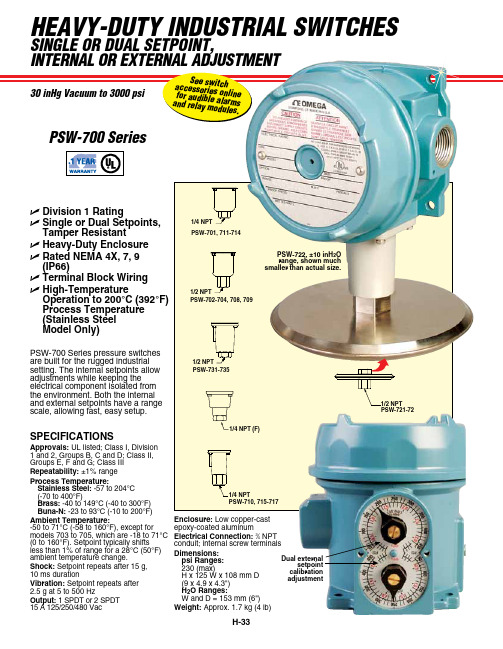
HEAVY-DUTY INDUSTRIAL SWITCHESSINgLE oR DUAL SETPoINT,PSW-700 SeriesDual external setpoint calibrationadjustment PSW-700 Series pressure switches are built for the rugged industrial setting. The internal setpoints allow adjustments while keeping the electrical component isolated from the environment. Both the internal and external setpoints have a range scale, allowing fast, easy setup.PSW-722, ±10 inH 2O range, shown much smaller than actual size.U Division 1 RatingU Single or Dual Setpoints, Tamper ResistantU Heavy-Duty Enclosure U Rated NEMA 4X, 7, 9 (IP66)U Terminal Block Wiring U High-TemperatureOperation to 200°C (392°F) Process Temperature (Stainless Steel Model Only)PSW-710, 715-7171/4 NPT1/4 NPT (F)PSW-731-7351/2 NPTPSW-702-704, 708, 709SPECIFICATIONSApprovals: UL listed; Class I, Division 1 and 2, Groups B, C and D; Class II, Groups E, F and G; Class III Repeatability: ±1% range Process Temperature:Stainless Steel: -57 to 204°C (-70 to 400°F)Brass: -40 to 149°C (-40 to 300°F) Buna-N: -23 to 93°C (-10 to 200°F)Ambient Temperature:-50 to 71°C (-58 to 160°F), except for models 703 to 705, which are -18 to 71°C (0 to 160°F). Setpoint typically shifts less than 1% of range for a 28°C (50°F) ambient temperature change.Shock: Setpoint repeats after 15 g, 10 ms durationVibration: Setpoint repeats after 2.5 g at 5 to 500 HzOutput: 1 SPDT or 2 SPDT 15 A 125/250/480 VacEnclosure: Low copper-cast epoxy-coated aluminumElectrical Connection: 3⁄4 NPT conduit; internal screw terminals Dimensions:psi Ranges:230 (max) H x 125 W x 108 mm D (9 x 4.9 x 4.3") H 2O Ranges:W and D = 153 mm (6") Weight: Approx. 1.7 kg (4 lb)PSW-721-72INDUSTRIAL SWITCHES PSW-707, 0 to 500 psirange, shown smallerthan actual size。
Leviton ATLAS-X1 Cat 6A Component-Rated UTP QUICKP

Page 1 of 2APPLICATIONThe ATLAS-X1 Cat 6A Component-Rated UTP QUICKPORT Jack supports 10GBASE-T networks. The jack is part of a complete ATLAS-X1 Cat 6A UTP system, ideal for the most demanding mission-critical network applications. The connector supports emerging technologies and will easily adapt to network trends.SPECIFICATIONThe jack shall meet or exceed the requirements for channel and component-level electrical transmission performance as described in ANSI/TIA-568.2-D (Cat 6A), ISO/IEC11801-1 (Class E A ), and EN 50173-1 (Class E A ). The jack shall be compliant with ANSI/TIA-1096-A, c(UL)us Listed, and be independently verified for electrical transmission performance and power delivery. The jack body shall be made of die-cast zinc and all plastic components shall be made of high-impact, fire-retardant plastic rated UL 94V-0. The jack shall support tool-free termination and re-termination and shall not require a specialized termination tool. The jack wiring shall be universal to accommodate T568A and T568B wiring schemes. The jack shall be available in 13 colors; more than established by the ANSI/TIA-606-C standard. The jack shall be offered in standard and shuttered styles and select jacks shall be supplied with interchangeable icons. The jack shall be compliant with IEEE 802.3 PoE Type 1, 2, 3, 4 (100 watts max).DESIGN CONSIDERATIONS• Use in any QUICKPORT™ housing to support Cat 6A UTP connectivity in surface-mount, flush-mount, or modular furniture outlets and field-configurable panels• Can be used in conjunction with other QUICKPORT snap-in modules for voice/data/video applications over UTP , coax, and fiber• To identify ports, use different colored modules andicons for each application (full selection of ANSI/TIA-606 compatible colors, 13 available)• Robust housing and shutter protects the jack in harsh environmentsATLAS-X1™ Cat 6A Component-Rated UTP QUICKPORT™ Jack6AUJK-xx6, ICONS-ICxFEATURES• Independently tested and guaranteed to exceed all component, permanent link, and channel margins• Patented Retention Force Technology™ (RFT) protects against tine damage and increases system longevity • For Power over Ethernet, RFT maintains contact force between plug and jack, preventing arcing from intermittent disconnects• Unique design supports tool-free termination andre-termination and requires no specialized termination tool • Short jack design supports a wider range of applications (e.g. shallow boxes, enclosures, bend radius, etc.)• Terminates from 26 to 22 AWG solid or stranded conductors for use on various cable types• Robust IDCs can withstand 20 re-termination cycles and jack contacts are tested for 750 plug-mating cycles to ensure system longevity• Available in 13 ANSI/TIA-606-C compatible colors • Tested and approved for use in air-handling spaces (plenum rating) in accordance with UL Standard 2043• Select jacks available with interchangeable icons (voice, data, A/V, blank) for easy ID• Jack with internal shutter protects against dust and debris • Solid metal body dissipates 53% more heat than plastic, minimizing damage from excess heat in PoE applications • Tine geometry prevents arcing damage where plug and jack make contactSTANDARDS & REGULATIONS• ANSI/TIA-568.2-D (Cat 6A)• ISO/IEC 11801-1 (Cat 6A)• EN 50173-1 (Cat 6A)• ANSI/TIA-1096-A (formerly FCC Part 68)• IEC 60603-7 (includes IEC 60512-5-2)• IEC 60512-99-002• IEEE 802.3 PoE Type 1, 2, 3, 4 (100 watts max)• Cisco UPOE, UPOE+ (90 watts max)• Power over HDBaseT™ PoH (95 watts max)• c(UL)us Listed (UL 1863)• UL 2043 Plenum Certified • RoHS 3• ETL verified to meet the IEC 60512-99-002 standard for support of IEEE 802.3 Type 4 PoE (100 watt) applicationsCOUNTRY OF ORIGINUSA and Mexico (Contact Customer Service for details)6AUJK-xx6, ICONS-ICxUSANetwork Solutions Headquarters +1 (800) 722 2082 *******************Leviton Berk-Tek Cable : +1 (800) 237 5835 ************************Asia Pacific+852 3620 2602********************Canada+1 (800) 461 2002**********************Europe+44 (0) 1592 772124 **********************Latin AmericaMX: +52 (55) 2128 6286 LATAM: +52 (55) 2333 5963 *********************Middle East & Africa +971 (4) 247 9800 *******************NETWORK SOLUTIONS PRODUCTS ARE AVAILABLE WORLDWIDE IN OVER 100 COUNTRIES. VISIT US ONLINE AT /NS TO LEARN MORE.Page 2 of 2For further support information, visit /ns/support6AUJK-xx6, ICONS-ICx6AUJK-xx6, ICONS-ICxMECHANICAL SPECIFICATIONSDimensions:See belowMaterials: Jack Body: Die-cast zincSpring-Wire Contacts: High quality, copper-based alloy, plated with 50 microinches of gold for lowest contact resistance andmaximum life Temp. (Storage):Temp. (Installation): Temp. (Operating):Humidity (Max.):WARRANTY INFORMATIONFor Leviton product warranties, go to /ns/warrantyPART NUMBERDescriptionStandard Jack Jack with Shutter GREENPACK™12-Pack Standard Jack ATLAS-X1™ Cat 6A Component-Rated UTP QUICKPORT™ Jack, white 6AUJK-RW66AUJK-SW66AUJK-CW6ATLAS-X1 Cat 6A Component-Rated UTP QUICKPORT Jack, light almond 6AUJK-RT66AUJK-ST6—ATLAS-X1 Cat 6A Component-Rated UTP QUICKPORT Jack, ivory 6AUJK-RI66AUJK-SI6—ATLAS-X1 Cat 6A Component-Rated UTP QUICKPORT Jack, yellow 6AUJK-RY66AUJK-SY6—ATLAS-X1 Cat 6A Component-Rated UTP QUICKPORT Jack, orange 6AUJK-RO66AUJK-SO6—ATLAS-X1 Cat 6A Component-Rated UTP QUICKPORT Jack, crimson 6AUJK-RC66AUJK-SC6—ATLAS-X1 Cat 6A Component-Rated UTP QUICKPORT Jack, dark red 6AUJK-RR66AUJK-SR6—ATLAS-X1 Cat 6A Component-Rated UTP QUICKPORT Jack, purple 6AUJK-RP66AUJK-SP6—ATLAS-X1 Cat 6A Component-Rated UTP QUICKPORT Jack, blue 6AUJK-RL66AUJK-SL66AUJK-CL6ATLAS-X1 Cat 6A Component-Rated UTP QUICKPORT Jack, green 6AUJK-RV66AUJK-SV6—ATLAS-X1 Cat 6A Component-Rated UTP QUICKPORT Jack, gray 6AUJK-RG66AUJK-SG6—ATLAS-X1 Cat 6A Component-Rated UTP QUICKPORT Jack, black6AUJK-RE66AUJK-SE66AUJK-CE6ATLAS-X1 Cat 6A Component-Rated UTP QUICKPORT Jack, brown6AUJK-RB66AUJK-SB6—Green (V)Blue (L)Purple (P)Crimson (C)Dark Red (R)Orange (O)Yellow (Y)Black (E)Gray (G)Ivory (I)Light Almond (T)Brown (B)Color-matched icons (ICONS-ICx) can be ordered separately in 72-quantity packs.x = icon color。
南京卫人科技有限公司 铱星终端 N5-I 技术说明书
编号密级版本铱星终端N5-I技术说明书编写校对审核会签批准南京卫人科技有限公司铱星终端N5-I技术说明书目次1概述 (1)2技术特征 (2)2.1产品功能 (2)2.2产品性能 (2)2.2.1GNSS单元指标 (2)2.2.2铱星单元指标 (3)2.2.3电源特性 (3)2.2.4环境适应性 (3)2.2.4其他 (4)3、组网拓扑 (4)4接口按键定义 (4)4.1对外接口 (4)4.2按键定义 (4)3.3指示灯定义 (5)4结构尺寸 (5)5终端连接 (6)6终端使用 (6)6.1使用步骤 (6)6.2注意事项 (7)7固件升级 (7)8标准配件 (7)9变更记录 (8)1概述铱星终端N5-I(以下简称终端)是我司推出的一款同时支持铱星SBD报文功能、全球定位功能、语音播报等功能以及蓝牙连接的终端产品。
终端与智能手机通过蓝牙连接,用户可以通过手机端专用app 实现位置服务、铱星短报文通信、GNSS定位、自动位置上报、SOS 报警等功能。
2技术特征2.1产品功能(1)铱星SBD短报文功能;(2)GNSS定位功能;(3)语音播报、提示功能;(4)支持终端状态查询功能;(5)支持蓝牙4.0连接;(6)支持一键开关机;(7)支持SOS按键报警功能;(8)支持落水自动报警功能;(9)内置锂电池供电;(10)支持磁吸充电;(11)支持设备内温湿度、气压参数检测功能。
2.2产品性能2.2.1GNSS单元指标●支持频点:BDS_B1/GPS_L1;●定位精度:≤10m;●冷启动时间:≤50s;●热启动时间:≤5s;●RNSS刷新率:1Hz(默认);2.2.2铱星单元指标●IRIDIUM频率:1616MHz to1626.5MHz●卫星覆盖范围:全球覆盖、卫星可视范围内无盲区;●卫星传输方式:全双向数据传输;●数据业务:铱星短数据SBD业务,●数据能力:单次发送最大340bytes,接收最大270bytes;●组网方式:终端-IP服务器-终端;●通信可靠性:高可靠性、没有数据丢失和误码;2.2.3电源特性●待机时间:模式待定;●报警工作时间:≥24小时(SOS模式);●电池充电:1.5A@5V(充电温度0℃-45℃)●电池放电:-20℃~+55℃●电池容量:2500mAh;2.2.4环境适应性●工作温度:-10℃~+60℃;●贮存温度:短期(1个月内):-20℃~+60℃中期(3个月内):-20℃~+45℃长期(1年):-5℃~+30℃●防护等级:IP67,抗1.2米落摔;2.2.4其他●重量:≤160±5g;●尺寸:98*59*23mm。
Motorola 3.5 kHz 产品说明书

RVN4126 3.59100-386-9100-386/T DEVICERVN41772-CD2-3.5MCS/MTSRVN41821-CD2-3.5XTS3000/SABER PORTABLE YES RKN4046KHVN9085 3.51-20 R NO HLN9359 PROG. STAND RVN4057 3.532 X 8 CODEPLUG NO3080385B23 & 5880385B30 MDVN4965 3.59100-WS/T CONFIG KITRVN4053 3.5ASTRO DIGITAL INTERFACE NO3080385B23RVN41842-CD RKN4046A (Portable) 2-3.5ASTRO PORTABLE /MOBILE YES3080369B73 or0180300B10 (Mobile) RVN41831-CD3080369B732-3.5ASTRO SPECTRA MOBILE YES(Low / Mid Power)0180300B10 (High Power) RVN4185CD ASTRO SPECTRA PLUS MOBILE NO MANY OPTIONS; SEESERVICE BRIEF#SB-MO-0101RVN4186CD ASTRO SPECTRA PLUS MANY OPTIONS;MOBILE/PORTABLE COMB SEE SERVICE BRIEF#SB-MO-0101RVN4154 3.5ASTROTAC 3000 COMPAR.3080385B23RVN5003 3.5ASTROTAC COMPARATORS NO3080399E31 Adpt.5880385B34RVN4083 3.5BSC II NO FKN5836ARVN4171 3.5C200RVN4029 3.5CENTRACOM SERIES II NO VARIOUS-SEE MANUAL6881121E49RVN4112 3.5COMMAND PLUS NORVN4149 3.5COMTEGRA YES3082056X02HVN6053CD CT250, 450, 450LS YES AAPMKN4004RVN4079 3.5DESKTRAC CONVENTIONAL YES3080070N01RVN4093 3.5DESKTRAC TRUNKED YES3080070N01RVN4091 3.5DGT 9000 DESKSET YES0180358A22RVN4114 3.5GLOBAL POSITIONING SYS.NO RKN4021AHVN8177 3.5GM/GR300/GR500/GR400M10/M120/130YES3080070N01RVN4159 3.5GP60 SERIES YES PMLN4074AHVN9128 3.5GP300 & GP350RVN4152 3.5GP350 AVSRVN4150 3.5GTX YES HKN9857 (Portable)3080070N01(Mobile) HVN9025CD HT CDM/MTX/EX SERIES YES AARKN4083/AARKN4081RiblessAARKN4075RIBLESS NON-USA RKN4074RVN4098H 3.5HT1000/JT1000-VISAR YES3080371E46(VISAR CONV)RVN4151 3.5HT1000 AVSRVN4098 3.5HT1000/ VISAR CONV’L.YES RKN4035B (HT1000) HVN9084 3.5i750YES HLN-9102ARVN4156 3.5LCS/LTS 2000YES HKN9857(Portable)3080070N01(Mobile) RVN4087 3.5LORAN C LOC. RECV’R.NO RKN4021ARVN4135 3.5M100/M200,M110,M400,R100 includesHVN9173,9177,9646,9774YES3080070N01RVN4023 3.5MARATRAC YES3080070N01RVN4019 3.5MAXTRAC CONVENTIONAL YES3080070N01RVN4139 3.5MAXTRAC LS YES3080070N01RVN4043 3.5MAXTRAC TRK DUPLEX YES3080070N01RVN4178CD MC SERIES, MC2000/2500DDN6124AW/DB25 CONNECTORDDN6367AW/DB9 CONNECTOR RVN41751-CD Rib to MIC connector 1-3.5MCS2000 RKN4062BRVN41131-3.5MCS2000RVN4011 3.5MCX1000YES3000056M01RVN4063 3.5MCX1000 MARINE YES3000056M01RVN4117 3.5MDC/RDLAP DEVICESRVN4105 3.5MOBILE PROG. TOOLRVN4119 3.5MOBITEX DEVICESRVN4128 3.5MPT1327-1200 SERIES YES SEE MANUALRVN4025 3.5MSF5000/PURC/ANALOG YES0180355A30RVN4077 3.5MSF5000/10000FLD YES0180355A30RVN4017K 3.5MT 1000YES RTK4205CRVN4148 3.5MTR 2000YES3082056X02RVN4140 3.5MTRI 2000NORVN41761-CD MTS2000, MT2000*, MTX8000, MTX90001-3.5*programmed by DOS which is included in the RVN4176RVN4131 3.5MTVA CODE PLUG FIXRVN4142 3.5MTVA DOCTOR YES3080070N01RVN4131 3.5MTVA3.EXERVN4013 3.5MTX800 & MTX800S YES RTK4205CRVN4097 1-CD MTX8000/MTX9000,MTS2000,MT2000*,* programmed by DOS which is included in the RVN4176HVN9067CD MTX850/MTX8250MTX950,MTX925RVN4138 3.5MTX-LS YES RKN4035DRVN4035 3.5MX 1000YES RTK4203CRVN4073 3.5MX 800YES RKN4006BHVN9395 P100, P200 LB, P50+, P210, P500, PR3000RVN4134 3.5P100 (HVN9175)P200 LB (HVN9794)P50+ (HVN9395)P210 (HVN9763)P500 (HVN9941)PR3000 (HVN9586)YES RTK4205HVN9852 3.5P110YES HKN9755A/REX1143 HVN9262 3.5P200 UHF/VHF YES RTK4205RVN4129 3.5PDT220YVN4051 3.5PORTABLE REPEATER Portable rptr.P1820/P1821AXRVN4061C 3.5PP 1000/500NO3080385B23 & 5880385B30 RVN5002 3.5QUANTAR/QUANTRO NO3O80369E31RVN4135 3.5R100 (HVN9177)M100/M200/M110/M400YES0180358A52RVN4146 3.5RPM500/660RVN4002 3.5SABER YES RTK4203CRVN4131 3.5SETTLET.EXEHVN9007 3.5SM50 & SM120YESRVN4039 3.5SMART STATUS YES FKN5825AHVN9054 3.5SOFTWARE R03.2 P1225YES3080070N01HVN9001 3.5SOFTWARE R05.00.00 1225LS YES HLN9359AHVN9012 3.5SP50RVN4001N 3.5SPECTRA YES3080369B73 (STANDARD)0180300B10 (HIGH POWER) RVN4099 3.5SPECTRA RAILROAD YES3080369B73RVN4110 3.5STATION ACCESS MODULE NO3080369E31RVN4089A 3.5STX TRANSIT YES0180357A54RVN4051 3.5SYSTEMS SABER YES RTK4203BRVN4075 3.5T5600/T5620 SERIES NO3080385B23HVN9060CD TC3000, TS3000, TR3000RVN4123 3.5VISAR PRIVACY PLUS YES3080371E46FVN4333 3.5VRM 100 TOOLBOX FKN4486A CABLE &ADAPTORRVN4133 3.5VRM 500/600/650/850NORVN4181CD XTS 2500/5000 PORTABLES RKN4105A/RKN4106A RVN41002- 3.5XTS3000 ASTRO PORTABLE/MOBILERVN4170 3.5XTS3500YES RKN4035DRIB SET UPRLN4008E RADIO INTERFACE BOX (RIB)0180357A57RIB AC POWER PACK 120V0180358A56RIB AC POWER PACK 220V3080369B71IBM TO RIB CABLE (25 PIN) (USE WITH XT & PS2)3080369B72IBM TO RIB CABLE (9 PIN)RLN443825 PIN (F) TO 9 PIN (M) ADAPTOR (USE W/3080369B72 FOR AT APPLICATION) 5880385B308 PIN MODULAR TO 25 PIN ”D” ADAPTOR (FOR T5600 ONLY)0180359A29DUPLEX ADAPTOR (MOSTAR/TRAXAR TRNK’D ONLY)Item Disk Radio RIB Cable Number Size Product Required Number Item Disk Radio RIB Cable Number Size Product Required NumberUtilizing your personal computer, Radio Service Software (RSS)/Customer Programming Software (CPS)/CustomerConfiguration Software (CCS) enables you to add or reprogram features/parameters as your requirements change. RSS/CPS/CCS is compatible with IBM XT, AT, PS/2 models 30, 50, 60 and 80.Requires 640K RAM. DOS 3.1 or later. Consult the RSS users guide for the computer configuration and DOS requirements. (ForHT1000, MT/MTS2000, MTX838/8000/9000, Visar and some newer products —IBM model 386, 4 MEG RAM and DOS 5.0 or higher are recommended.) A Radio Interface Box (RIB) may be required as well as the appropriate cables. The RIB and cables must be ordered separately.Licensing:A license is required before a software (RVN) order is placed. The software license is site specific (customer number and ultimate destination tag). All sites/locations must purchase their own software.Be sure to place subsequent orders using the original customer number and ship-to-tag or other licensed sites; ordering software without a licensed customer number and ultimate tag may result in unnecessary delays. To obtain a no charge license agreement kit, order RPX4719. To place an order in the U.S. call 1-800-422-4210. Outside the U.S., FAX 847-576-3023.Subscription Program:The purchase of Radio ServiceSoftware/Customer Programming/Customer ConfigurationSoftware (RVN & HVN kits) entitles the buyer/subscriber to three years of free upgrades. At the end of these three years, the sub-scriber must purchase the same Radio Service Software kit to receive an additional three years of free upgrades. If the sub-scriber does not elect to purchase the same Radio Service Software kit, no upgrades will be sent. Annually a subscription status report is mailed to inform subscribers of the RSS/CPS/CCS items on our database and their expiration dates.Notes:1)A subscription service is offered on “RVN”-Radio Service Software/Customer Programming/Customer Configuration Software kits only.2)“RVN” software must only be procured through Radio Products and Services Division (RPSD). Software not procured through the RPSD will not be recorded on the subscription database; upgrades will not be mailed.3)Upgrades are mailed to the original buyer (customer number & ultimate tag).4)SP software is available through the radio product groups.The Motorola General Radio Service Software Agreement is now available on Motorola Online. If you need assistance please feel free to submit a “Contact Us” or call 800-422-4210.SMART RIB SET UPRLN1015D SMART RIB0180302E27 AC POWER PACK 120V 2580373E86 AC POWER PACK 220V3080390B49SMARTRIB CABLE (9 PIN (F) TO 9 PIN (M) (USE WITH AT)3080390B48SMARTRIB CABLE (25 PIN (F) TO 9 PIN (M) (USE WITH XT)RLN4488ASMART RIB BATTERY PACKWIRELESS DATA GROUP PRODUTS SOFTWARERVN4126 3.59100-386/9100T DEVICES MDVN4965 3.59100-WS/T CONFIG’TN RVN41173.5MDC/RDLAP DEVICESPAGING PRODUCTS MANUALS6881011B54 3.5ADVISOR6881029B90 3.5ADVISOR ELITE 6881023B20 3.5ADVISOR GOLD 6881020B35 3.5ADVISOR PRO FLX 6881032B30 3.5BR8506881032B30 3.5LS3506881032B30 3.5LS5506881032B30 3.5LS7506881033B10 3.5LS9506881035B20 3.5MINITOR III8262947A15 3.5PAGEWRITER 20008262947A15 3.5PAGEWRITER 2000X 6881028B10 3.5TALKABOUT T3406881029B35 3.5TIMEPORT P7308262947A15 3.5TIMEPORT P930NLN3548BUNIVERSAL INTERFACE KITItem Disk Radio NumberSize Product。
TI产品中文版说明书
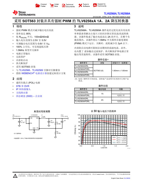
Load (A)E f f i c i e n c y (%)0.00.51.0 1.52.06065707580859095100D008V INV OUTL1TLV62569AProduct Folder Order Now Technical Documents Tools &SoftwareSupport &CommunityTLV62568A ,TLV62569AZHCSI23B –APRIL 2018–REVISED MARCH 2020采用SOT563封装并具有强制PWM 的TLV6256xA 1A 、2A 降压转换器1特性•强制PWM 模式可减少输出电压纹波•效率高达95%•低R DS(ON)开关:100m Ω/60m Ω•输入电压范围为2.5V 至5.5V •可调输出电压范围为0.6V 至V IN •100%占空比,可实现超低压降• 1.5MHz 典型开关频率•电源正常输出•过流保护•内部软启动•热关断保护•采用SOT563封装•与TLV62568、TLV62569引脚对引脚兼容•借助WEBENCH ®电源设计器创建定制设计方案2应用•通用负载点(POL)电源•STB 和DVR •IP 网络摄像头•无线路由器•固态硬盘(SSD)–企业级3说明TLV62568A 、TLV62569A 器件是经过优化而具有高效率和紧凑型解决方案尺寸的同步降压型直流/直流转换器。
该器件集成了输出电流高达2A 的开关。
在整个负载范围内,该器件将以1.5MHz 开关频率在脉宽调制(PWM)模式下运行。
关断时,流耗减少至2μA 以下。
内部软启动电路可限制启动期间的浪涌电流。
此外,还内置了诸如输出过流保护、热关断保护和电源正常输出等其他特性。
该器件采用SOT563封装。
器件信息(1)器件型号封装封装尺寸(标称值)TLV62568ADRL SOT563(6)1.60mm x 1.60mmTLV62568APDRL TLV62569ADRL TLV62569APDRL(1)如需了解所有可用封装,请参阅产品说明书末尾的可订购产品附录。
RCI NEXT DK 1 的用户手册说明书
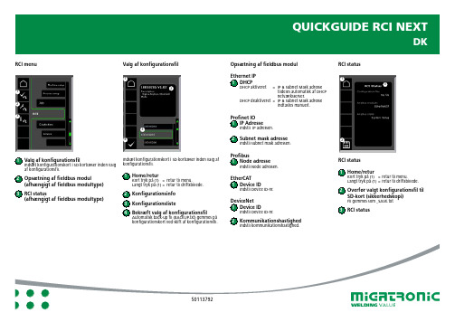
Opsætning af fieldbus modul
Ethernet IP 1 DHCP
DHCP aktiveret = IP & Subnet Mask adresse tildeles automatisk af DHCP netværksserver.
anzeige
2 Konfig. info 3 Konfig. Liste 4 Bestätigung der Konfigurationsdatei
Automatische Back-up-Datei (BACKUP.txt) auf der Konfigurationskarte beim Wechseln der Konfigurationsdatei speichern.
2 Setup des Fieldbus-Moduls (je nach Typ des Fieldbus-Modch Typ des Fieldbus-Moduls)
QUICKGUIDE RCI NEXT
DE
Wahl der Konfigurationsdatei
QUICKGUIDE RCI NEXT
DK
RCI menu
1 2 3
Valg af konfigurationsfil
1 2
3 4
1 Valg af konfigurationsfil
Indsæt konfigurationskort i SD kortlæser inden valg af konfigurationsfil.
笔记本维修常用芯片引脚说明
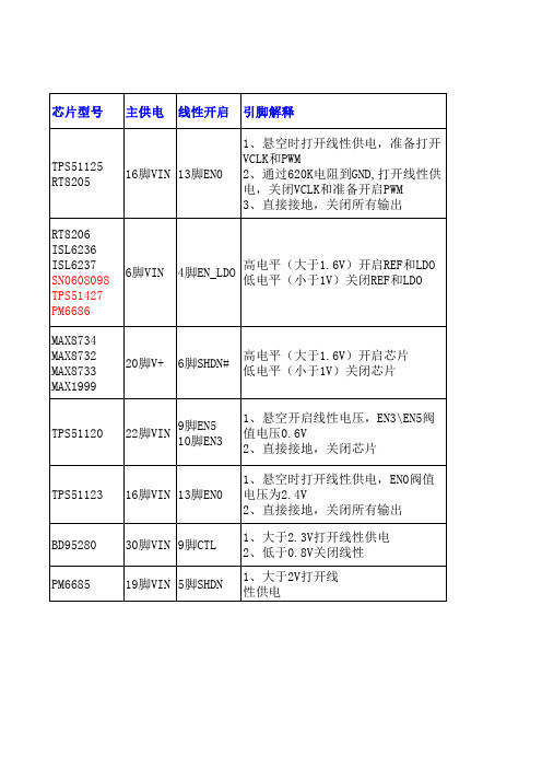
先有LDO5,给VCC供电(根据典型应用图判断) VCC有电后,再产生REF(根据内部框图判断) REF稳定后,再产生LDO3(根据引脚定义判断)
先有VREG5,再给V5FILT供电(根据典型应用图 判断) V5FILT正常后,再产生VREF2(根据内部框图判 断)
1、大于2V打开线 性供电
常用待机
常用待机芯片
PWM开启 引脚解释
1脚 ENTRIP1 2脚 ENTRIP2
通道1和通道2的开启和过流设定脚 1、直接接地,关闭PWM 2、通过电阻到地,作为电流极限设定
高电平开启(大于2.5V),低电平关闭 14脚EN1 (小于0.8V),当EN1连接REF时,PWM1会 27脚EN2 在PWM2稳定后延时开启,当EN2连接到REF
6脚VIN
4脚EN_LDO
高电平(大于1.6V)开启REF和LDO 低电平(小于1V)关闭REF和LDO
MAX8734 MAX8732 MAX8733 MAX1999
20脚V+
6脚SHDN#
高电平(大于1.6V)开启芯片 低电平(小于1V)关闭芯片
TPS51120
22脚VIN
9脚EN5 10脚EN3
时,PWM2会在PWM1稳定后延时开启
3脚ON3 4脚ON5
高电平开启(大于2.4V),低电平关闭 (低于0.8V),把ON3接REF,3.3V的PWM 会在5V的PWM稳定后延时启动
12脚EN2 29脚EN1
高电平(大于2.7V)直接开启 大于0.9V时会延时开启 低电平(小于0.5V)关闭
18脚ENC
marvell w 无线wifi智能模块

BL-R8801MS1Product SpecificationIEEE 802.11b/g/n WLAN SDIO ModuleVersion: 0.1CustomerDateModel Name BL-R8801MS1Part NO.Blink Approve FieldENGINEER QC SALESCustomer Approve FieldENGINEER QC MANUFACTORY PURCHASINGContentContent (1)0.Revision History (2)1. General Description (2)2.The range of applying (2)3. Product Specification (2)3.1 Function Block diagram (2)3.2 Electrical and Performance Specification (3)3.5 Product Photo (4)3.6 Mechanical Specification (5)3.7 Product Pin Definition (5)4. Supported platform (6)5. Peripheral Schematic Reference Design (6)5.1 WiFi RF Circuit reference pictures (6)6. Typical Solder Reflow Profile (7)0.Revision HistoryDate Documentrevision Productrevision Change Description2014/11/11 0.1 V0.1 Draft initial release1. General DescriptionBL-R8801MS1product is designed base on MARVELL 88W8801 chipset .It is a highly integrated single-band (2.4GHz) IEEE 802.11n 1X1 System-on-Chip (SoC), specifically designed to support High Throughput data rates for next generation WLAN products. It supports IEEE802.11i safety protocol, along with IEEE 802.11e standard service quality. It supports the new data encryption on 64/128 bit WEP and safety mechanism on WPA-PSK/WPA2-PSK, WPA/WPA2. It can implement the wireless network function on the laptop/desktop/MID and other wireless devices easily .2.The range of applyingMID, networking camera, STB GPS, E-book, Hard disk player, Network Radios, PSP and other device which need be supported by wireless networking.3. Product Specification3.1 Function Block diagram3.2 Electrical and Performance SpecificationItemDescription Product Name BL-R8801MS1Major Chipset MARVELL 88W8801Host Interface SDIOStandard IEEE 802.11b, IEEE 802.11g,IEEE 802.11n, Frequency Range 2.4GHz~2.4835GHzModulation Type 802.11b: CCK, DQPSK, DBPSK802.11g: 64-QAM,16-QAM, QPSK, BPSK 802.11n: 64-QAM,16-QAM, QPSK, BPSK Working ModeInfrastructure, Ad-HocData Transfer Rate 1,2,5.5,6,11,12,18,22,24,30,36,48,54,and maximum of 72.2Mbps Spread SpectrumIEEE 802.11b: DSSS (Direct Sequence Spread Spectrum) IEEE 802.11g/n:OFDM (Orthogonal Frequency DivisionMultiplexing)Sensitivity @PER1M: -92dBm@8%PER 6M: -88dBm@10%PER 11M:-86dBm@8%PER 54M:-72dBm@10%PER 72.2M:- 68dBm@10%PERRF Power17dBm@11b,14dBm@11g ,13dBm@11nAntenna typeConnect to the external antenna through the half holeThe transmit distance Indoor 100M, Outdoor 300M, according the local environment Dimension(L*W*H) 13 x 13.5 x 1.46mm (LxWxH) ;Tolerance: +-0.15mm Power supply3.3V +/-0.2VPower Consumption standby mode 80mA@3.3V , TX mode 250mA@3.3V Clock source38.4MHz Working Temperature -40°C to +85°CStorage temperature-55°C ~ +125°C3.3 Product PhotoTOP Bottom3.4 Mechanical SpecificationModule dimension: Typical (W x L x H): 13mmx13.5mmx1.46mm Tolerance : +/-0.15mm3.5 Product Pin Definition4. Supported platformSupport Linux platform.5. Peripheral Schematic Reference Design 5.1 WiFi RF Circuit reference picturesPls reserve a “pi” circuit for antenna matching. The “pi” circuit’s value depends on the matching result.6. Typical Solder Reflow Profile。
雷客惊艳产品操作手册(2011最终版)
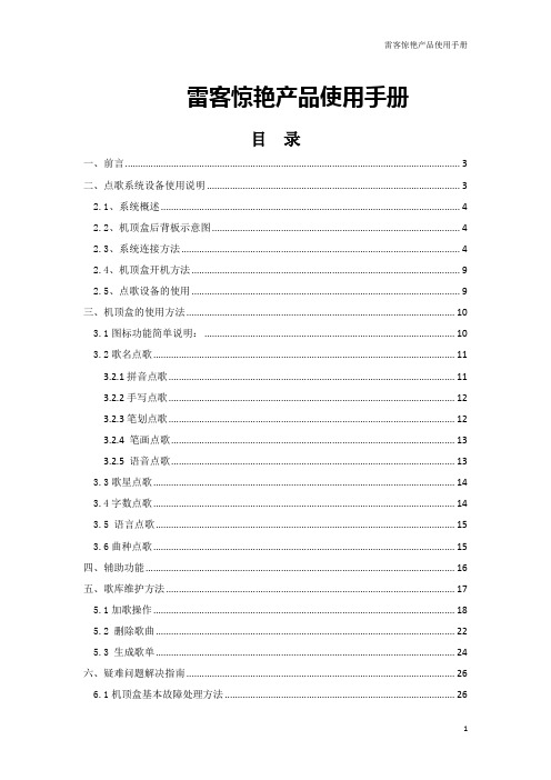
雷客惊艳产品使用手册目录一、前言 (3)二、点歌系统设备使用说明 (3)2.1、系统概述 (4)2.2、机顶盒后背板示意图 (4)2.3、系统连接方法 (4)2.4、机顶盒开机方法 (9)2.5、点歌设备的使用 (9)三、机顶盒的使用方法 (10)3.1图标功能简单说明: (10)3.2歌名点歌 (11)3.2.1拼音点歌 (11)3.2.2手写点歌 (12)3.2.3笔划点歌 (12)3.2.4 笔画点歌 (13)3.2.5 语音点歌 (13)3.3歌星点歌 (14)3.4字数点歌 (14)3.5 语言点歌 (15)3.6曲种点歌 (15)四、辅助功能 (16)五、歌库维护方法 (17)5.1加歌操作 (18)5.2删除歌曲 (22)5.3生成歌单 (24)六、疑难问题解决指南 (26)6.1机顶盒基本故障处理方法 (26)6.2触摸屏基本故障处理方法 (26)一、前言尊敬的朋友:您好!感谢您使用雷客“惊艳”系列点歌系统。
通过这本安装手册,我们将雷客“惊艳”系列点歌系统(单机版)的使用方法较详细地介绍给您。
感谢您花费宝贵时间对雷客“惊艳”系列点歌系统的关注,我们还将继续努力,与您一起来打造您所需要的点歌系统!一起享受音乐带来的乐趣!谢谢!重要提示:雷客公司网址:技术支持电话:010-********;010-********技术在线支持QQ群:102764665(请注明:雷客支持)二、点歌系统设备使用说明“惊艳”系列机顶盒2.1、系统概述“惊艳”机顶盒采用硬盘的海量存储。
单机运行,无须网络;即装即用,简单易学,只要与功放和电视机相连,开机即可使用。
2.2、机顶盒后背板示意图背板接口说明:(按照从左至右,从上至下的顺序,分别为:)1、USB端口2、VGA显示器接口3、语音点歌麦克接口4、外置遥控器接口5、录音(左声道)6、录音(右声道)7、音频(左声道)8、音频(右声道)9、视频110、视频211、鼠标接口12、键盘接口13、串口114、串口215、HDMI接口16、网络接口2.3、系统连接方法系统的连接方法如图所示。
SCI Dual NPN Bias Resistor Transistors 数据手册说明书

MUN5211DW1,NSBC114EDXV6,NSBC114EDP6Dual NPN Bias Resistor TransistorsR1 = 10 k W, R2 = 10 k WNPN Transistors with Monolithic Bias Resistor NetworkThis series of digital transistors is designed to replace a single device and its external resistor bias network. The Bias Resistor Transistor (BRT) contains a single transistor with a monolithic bias network consisting of two resistors; a series base resistor and a base-emitter resistor. The BRT eliminates these individual components by integrating them into a single device. The use of a BRT can reduce both system cost and board space.Features•Simplifies Circuit Design•Reduces Board Space•Reduces Component Count•S and NSV Prefix for Automotive and Other Applications Requiring Unique Site and Control Change Requirements;AEC-Q101 Qualified and PPAP Capable*•These Devices are Pb-Free, Halogen Free/BFR Free and are RoHS CompliantMAXIMUM RATINGS(T A = 25°C, common for Q1 and Q2, unless otherwise noted)Rating Symbol Max Unit Collector-Base Voltage V CBO50Vdc Collector-Emitter Voltage V CEO50Vdc Collector Current − Continuous I C100mAdc Input Forward Voltage V IN(fwd)40Vdc Input Reverse Voltage V IN(rev)10Vdc Stresses exceeding those listed in the Maximum Ratings table may damage the device. If any of these limits are exceeded, device functionality should not be assumed, damage may occur and reliability may be affected. ORDERING INFORMATIONDevice Package Shipping†MUN5211DW1T1G,SMUN5211DW1T1G*SOT−3633,000 / Tape & Reel NSVMUN5211DW1T2G*SOT−3633,000 / Tape & Reel NSVMUN5211DW1T3G*SOT−36310,000 / Tape & Reel NSBC114EDXV6T1G,NSVBC114EDXV6T1G*SOT−5634,000 / Tape & Reel NSBC114EDXV6T5G SOT−5638,000 / Tape & ReelNSBC114EDP6T5G SOT−9638,000 / Tape & Reel†For information on tape and reel specifications, including part orientation and tape sizes, please refer to our Tape and Reel Packaging SpecificationsMARKING DIAGRAMSPIN CONNECTIONS7A M GG17A/A=Specific Device CodeM=Date Code*G=Pb-Free Package (Note: Microdot may be in either location) *Date Code orientation may vary depending up-on manufacturing location.SOT−363CASE 419BSOT−563CASE 463A(1)(2)(3)(6)(5)(4)SOT−963CASE 527ADM1A7A M GG16THERMAL CHARACTERISTICSCharacteristic Symbol Max Unit MUN5211DW1 (SOT−363) ONE JUNCTION HEATEDTotal Device DissipationT A = 25°C(Note1)(Note2)Derate above 25°C(Note1)(Note2)P D1872561.52.0mWmW/°CThermal Resistance,(Note1) Junction to Ambient(Note2)R q JA670490°C/WMUN5211DW1 (SOT−363) BOTH JUNCTION HEATED (Note3)Total Device DissipationT A = 25°C(Note1)(Note2)Derate above 25°C(Note1)(Note2)P D2503852.03.0mWmW/°CThermal Resistance,Junction to Ambient(Note1)(Note2)R q JA493325°C/WThermal Resistance, Junction to Lead(Note1)(Note2)R q JL188208°C/WJunction and Storage Temperature Range T J, T stg−55 to +150°C NSBC114EDXV6 (SOT−563) ONE JUNCTION HEATEDTotal Device DissipationT A = 25°C(Note1)Derate above 25°C(Note1)P D3572.9mWmW/°CThermal Resistance,Junction to Ambient(Note1)R q JA350°C/WNSBC114EDXV6 (SOT−563) BOTH JUNCTION HEATED (Note3)Total Device DissipationT A = 25°C(Note1)Derate above 25°C(Note1)P D5004.0mWmW/°CThermal Resistance,Junction to Ambient(Note1)R q JA250°C/WJunction and Storage Temperature Range T J, T stg−55 to +150°C NSBC114EDP6 (SOT−963) ONE JUNCTION HEATEDTotal Device DissipationT A = 25°C(Note4)(Note5)Derate above 25°C(Note4)(Note5)P D2312691.92.2MWmW/°CThermal Resistance,Junction to Ambient(Note4)(Note5)R q JA540464°C/WNSBC114EDP6 (SOT−963) BOTH JUNCTION HEATED (Note3)Total Device DissipationT A = 25°C(Note4)(Note5)Derate above 25°C(Note4)(Note5)P D3394082.73.3MWmW/°CThermal Resistance,Junction to Ambient(Note4)(Note5)R q JA369306°C/WJunction and Storage Temperature Range T J, T stg−55 to +150°C 1.FR−4 @ Minimum Pad.2.FR−4 @ 1.0×1.0 Inch Pad.3.Both junction heated values assume total power is sum of two equally powered channels.4.FR−4 @ 100mm2, 1 oz. copper traces, still air.5.FR−4 @ 500mm2, 1 oz. copper traces, still air.ELECTRICAL CHARACTERISTICS (T A=25°C, common for Q1 and Q2, unless otherwise noted)Characteristic Symbol Min Typ Max Unit OFF CHARACTERISTICSCollector-Base Cutoff Current (V CB=50V, I E=0)I CBO−−100nAdcCollector-Emitter Cutoff Current (V CE=50V, I B=0)I CEO−−500nAdcEmitter-Base Cutoff Current (V EB=6.0V, I C=0)I EBO−−0.5mAdcCollector-Base Breakdown Voltage (I C=10m A, I E=0)V(BR)CBO50−−VdcCollector-Emitter Breakdown Voltage (Note6) (I C=2.0mA, I B=0)V(BR)CEO50−−VdcON CHARACTERISTICSDC Current Gain (Note6) (I C=5.0mA, V CE=10V)h FE3560−Collector-Emitter Saturation Voltage (Note6) (I C=10mA, I B=0.3mA)V CE(sat)−−0.25VInput Voltage (Off)(V CE=5.0V, I C=100m A)V i(off)− 1.2−VdcInput Voltage (On)(V CE=0.2V, I C=10mA)V i(on)−2.0−VdcOutput Voltage (On)(V CC=5.0V, V B=2.5V, R L=1.0k W)V OL−−0.2VdcOutput Voltage (Off)(V CC=5.0V, V B=0.5V, R L=1.0k W)V OH4.9−−Vdc Input Resistor R17.01013k W Resistor Ratio R1/R20.8 1.0 1.2Product parametric performance is indicated in the Electrical Characteristics for the listed test conditions, unless otherwise noted. Product performance may not be indicated by the Electrical Characteristics if operated under different conditions.6.Pulsed Condition: Pulse Width=300ms, Duty Cycle ≤2%.Figure 1. Derating CurveAMBIENT TEMPERATURE (°C)PD,POWERDISSIPATION(mW)(1) SOT−363; 1.0×1.0 Inch Pad(2) SOT−563; Minimum Pad(3) SOT−963; 100mm2, 1 oz. Copper TraceTYPICAL CHARACTERISTICS MUN5211DW1, NSBC114EDXV6Figure 2. V CE(sat) vs. I CI C , COLLECTOR CURRENT (mA)1010.1Figure 3. DC Current GainFigure 4. Output Capacitance 0.10.010.001I C , COLLECTOR CURRENT (mA)100010010I C , COLLECTOR CURRENT (mA)Figure 5. Output Current vs. Input Voltage1010.1V in , INPUT VOLTAGE (V)Figure 6. Input Voltage vs. Output Current3.62.80.41.20V R , REVERSE VOLTAGE (V)V C E (s a t ), C O L L E C T O R −E M I T T E R V O L T A G E (V )h F E , D C C U R R E N T G A I N0.81.62.02.43.2C o b , O U T P U T C A P A C I T A N C E (p F )I C , C O L L E C T O R C U R R E N T (m A )V i n , I N P U T V O L T A G E (V )TYPICAL CHARACTERISTICSNSBC114EDP6Figure 7. V CE(sat) vs. I CFigure 8. DC Current GainI C , COLLECTOR CURRENT (mA)I C , COLLECTOR CURRENT (mA)0.010.11Figure 9. Output CapacitanceFigure 10. Output Current vs. Input VoltageV R , REVERSE VOLTAGE (V)V in , INPUT VOLTAGE (V)Figure 11. Input Voltage vs. Output CurrentI C , COLLECTOR CURRENT (mA)V C E (s a t ), C O L L E C T O R −E M I T T E R V O L T A G E (V )h F E , D C C U R R E N T G A I NC o b , O U T P U T C A P A C I T A N C E (p F )I C , C O L L E C T O R C U R R E N T (m A )V i n , I N P U T V O L T A G E (V )SC −88/SC70−6/SOT −363CASE 419B −02ISSUE YDATE 11 DEC 2012SCALE 2:1NOTES:1.DIMENSIONING AND TOLERANCING PER ASME Y14.5M, 1994.2.CONTROLLING DIMENSION: MILLIMETERS.3.DIMENSIONS D AND E1 DO NOT INCLUDE MOLD FLASH,PROTRUSIONS, OR GATE BURRS. MOLD FLASH, PROTRU-SIONS, OR GATE BURRS SHALL NOT EXCEED 0.20 PER END.4.DIMENSIONS D AND E1 AT THE OUTERMOST EXTREMES OF THE PLASTIC BODY AND DATUM H.5.DATUMS A AND B ARE DETERMINED AT DATUM H.6.DIMENSIONS b AND c APPLY TO THE FLAT SECTION OF THE LEAD BETWEEN 0.08 AND 0.15 FROM THE TIP .7.DIMENSION b DOES NOT INCLUDE DAMBAR PROTRUSION.ALLOWABLE DAMBAR PROTRUSION SHALL BE 0.08 TOTAL IN EXCESS OF DIMENSION b AT MAXIMUM MATERIAL CONDI-TION. THE DAMBAR CANNOT BE LOCATED ON THE LOWER RADIUS OF THE FOOT.XXXM G G XXX = Specific Device Code M = Date Code*G = Pb −Free Package GENERICMARKING DIAGRAM*16STYLES ON PAGE 2DIM MIN NOM MAX MILLIMETERS A −−−−−− 1.10A10.00−−−0.10dddb 0.150.200.25C 0.080.150.22D 1.80 2.00 2.20−−−−−−0.0430.000−−−0.0040.0060.0080.0100.0030.0060.0090.0700.0780.086MIN NOM MAX INCHES0.100.004E1 1.15 1.25 1.35e 0.65 BSC L 0.260.360.462.00 2.10 2.200.0450.0490.0530.026 BSC0.0100.0140.0180.0780.0820.086(Note: Microdot may be in either location)*Date Code orientation and/or position may vary depending upon manufacturing location.*For additional information on our Pb −Free strategy and soldering details, please download the ON Semiconductor Soldering and Mounting Techniques Reference Manual, SOLDERRM/D.SOLDERING FOOTPRINT*DIMENSIONS: MILLIMETERS0.306XRECOMMENDEDSIDE VIEWEND VIEWPLANEDETAIL AE A20.700.90 1.000.0270.0350.039L20.15 BSC 0.006 BSC aaa 0.150.006bbb 0.300.012ccc 0.100.0046X*This information is generic. Please refer to device data sheet for actual part marking.Pb −Free indicator, “G” or microdot “G ”, may or may not be present. Some products may not follow the Generic Marking.MECHANICAL CASE OUTLINEPACKAGE DIMENSIONSSTYLE 1:PIN 1.EMITTER 22.BASE 23.COLLECTOR 14.EMITTER 15.BASE 16.COLLECTOR 2STYLE 3:CANCELLEDSTYLE 2:CANCELLEDSTYLE 4:PIN 1.CATHODE2.CATHODE3.COLLECTOR4.EMITTER5.BASE6.ANODESTYLE 5:PIN 1.ANODE2.ANODE3.COLLECTOR4.EMITTER5.BASE6.CATHODESTYLE 6:PIN 1.ANODE 22.N/C3.CATHODE 14.ANODE 15.N/C6.CATHODE 2STYLE 7:PIN 1.SOURCE 22.DRAIN 23.GATE 14.SOURCE 15.DRAIN 16.GATE 2STYLE 8:CANCELLEDSTYLE 11:PIN 1.CATHODE 22.CATHODE 23.ANODE 14.CATHODE 15.CATHODE 16.ANODE 2STYLE 9:PIN 1.EMITTER 22.EMITTER 13.COLLECTOR 14.BASE 15.BASE 26.COLLECTOR 2STYLE 10:PIN 1.SOURCE 22.SOURCE 13.GATE 14.DRAIN 15.DRAIN 26.GATE 2STYLE 12:PIN 1.ANODE 22.ANODE 23.CATHODE 14.ANODE 15.ANODE 16.CATHODE 2STYLE 13:PIN 1.ANODE2.N/C3.COLLECTOR4.EMITTER5.BASE6.CATHODE STYLE 14:PIN 1.VREF2.GND3.GND4.IOUT5.VEN6.VCCSTYLE 15:PIN 1.ANODE 12.ANODE 23.ANODE 34.CATHODE 35.CATHODE 26.CATHODE 1STYLE 17:PIN 1.BASE 12.EMITTER 13.COLLECTOR 24.BASE 25.EMITTER 26.COLLECTOR 1STYLE 16:PIN 1.BASE 12.EMITTER 23.COLLECTOR 24.BASE 25.EMITTER 16.COLLECTOR 1STYLE 18:PIN 1.VIN12.VCC3.VOUT24.VIN25.GND6.VOUT1STYLE 19: PIN 1.I OUT2.GND3.GND4.V CC5.V EN6.V REF STYLE 20:PIN 1.COLLECTOR2.COLLECTOR3.BASE4.EMITTER5.COLLECTOR6.COLLECTORSTYLE 22:PIN 1.D1 (i)2.GND3.D2 (i)4.D2 (c)5.VBUS6.D1 (c)STYLE 21:PIN 1.ANODE 12.N/C3.ANODE 24.CATHODE 25.N/C6.CATHODE 1STYLE 23:PIN 1. Vn2.CH13.Vp4.N/C5.CH26.N/CSTYLE 24:PIN 1.CATHODE2.ANODE3.CATHODE4.CATHODE5.CATHODE6.CATHODESTYLE 25:PIN 1.BASE 12.CATHODE3.COLLECTOR 24.BASE 25.EMITTER6.COLLECTOR 1STYLE 26:PIN 1.SOURCE 12.GATE 13.DRAIN 24.SOURCE 25.GATE 26.DRAIN 1STYLE 27:PIN 1.BASE 22.BASE 13.COLLECTOR 14.EMITTER 15.EMITTER 26.COLLECTOR 2STYLE 28:PIN 1.DRAIN2.DRAIN3.GATE4.SOURCE5.DRAIN6.DRAINSTYLE 29:PIN 1.ANODE2.ANODE3.COLLECTOR4.EMITTER5.BASE/ANODE6.CATHODESC−88/SC70−6/SOT−363CASE 419B−02ISSUE YDATE 11 DEC 2012STYLE 30:PIN 1.SOURCE 12.DRAIN 23.DRAIN 24.SOURCE 25.GATE 16.DRAIN 1Note: Please refer to datasheet forstyle callout. If style type is not calledout in the datasheet refer to the devicedatasheet pinout or pin assignment.SOT −563, 6 LEADCASE 463A ISSUE HDATE 26 JAN 2021SCALE 4:16MECHANICAL CASE OUTLINEPACKAGE DIMENSIONSSOT −563, 6 LEADCASE 463A ISSUE HDATE 26 JAN 2021XX = Specific Device Code M = Month Code G = Pb −Free PackageXX MG GENERICMARKING DIAGRAM*1*This information is generic. Please refer todevice data sheet for actual part marking.Pb −Free indicator, “G” or microdot “G ”, may or may not be present. Some products maynot follow the Generic Marking.SOT −963CASE 527AD −01ISSUE EDATE 09 FEB 2010SCALE 4:1GENERICMARKING DIAGRAM*X = Specific Device Code M = Month Code*This information is generic. Please refer to device data sheet for actual part marking.Pb −Free indicator, “G” or microdot “ G ”,may or may not be present.DIM MIN NOM MAX MILLIMETERS A 0.340.370.40b 0.100.150.20C 0.070.120.17D 0.95 1.001.05E 0.750.800.85e 0.35 BSC 0.95 1.00 1.05HE ANOTES:1.DIMENSIONING AND TOLERANCING PER ASME Y14.5M, 1994.2.CONTROLLING DIMENSION: MILLIMETERS3.MAXIMUM LEAD THICKNESS INCLUDES LEAD FINISH THICKNESS. MINIMUM LEADTHICKNESS IS THE MINIMUM THICKNESS OF BASE MATERIAL.4.DIMENSIONS D AND E DO NOT INCLUDE MOLD FLASH, PROTRUSIONS, OR GATE BURRS.XM 1STYLE 1:PIN 1.EMITTER 12.BASE 13.COLLECTOR 24.EMITTER 25.BASE 26.COLLECTOR 1STYLE 2:PIN 1.EMITTER 12.EMITTER23.BASE 24.COLLECTOR 25.BASE 16.COLLECTOR 1STYLE 3:PIN 1.CATHODE 12.CATHODE 13.ANODE/ANODE 24.CATHODE 25.CATHODE 26.ANODE/ANODE 1STYLE 4:PIN 1.COLLECTOR2.COLLECTOR3.BASE4.EMITTER5.COLLECTOR6.COLLECTOR STYLE 6:PIN 1.CATHODE2.ANODE3.CATHODE4.CATHODE5.CATHODE6.CATHODE STYLE 5:PIN 1.CATHODE2.CATHODE3.ANODE4.ANODE5.CATHODE6.CATHODE STYLE 7:PIN 1.CATHODE2.ANODE3.CATHODE4.CATHODE5.ANODE6.CATHODE STYLE 8:PIN 1.DRAIN2.DRAIN3.GATE4.SOURCE5.DRAIN6.DRAINSTYLE 9:PIN 1.SOURCE 12.GATE 13.DRAIN 24.SOURCE 25.GATE 26.DRAIN 1STYLE 10:PIN 1.CATHODE 12.N/C3.CATHODE 24.ANODE 25.N/C6.ANODE 1TOP VIEW SIDE VIEWDIMENSIONS: MILLIMETERSRECOMMENDED MOUNTING FOOTPRINTL 0.19 REF L20.050.100.156X MECHANICAL CASE OUTLINEPACKAGE DIMENSIONSPUBLICATION ORDERING INFORMATIONTECHNICAL SUPPORT North American Technical Support:Voice Mail: 1 800−282−9855 Toll Free USA/Canada Phone: 011 421 33 790 2910LITERATURE FULFILLMENT :Email Requests to:*******************onsemi Website: Europe, Middle East and Africa Technical Support:Phone: 00421 33 790 2910For additional information, please contact your local Sales Representative ◊。
Elkay单孔单控aucet 产品说明书

PRODUCT SPECIFICATIONSElkay® Single Hole with Single Control Faucet with 10" Arc Tube Spout 6" Wristblade Handle Chrome. Faucet has a flow rate of 1.5 GPM, and is made of Chrome-plated Brass material, with a Quarter Turn Ceramic Disc - Cold valve. Faucet requires 1 faucet holes.Mounting Type:Deck Mount Special Features:Low FlowSolid Brass Construction Spout Swing Restriction PinFinish: Chrome (CR) Handle Type: 6" Wristblade Handle Deck Clearance: 6-1/2" Spout Reach: 10" Spout Height: 9-1/8" Hole Drillings: 1 Material: Chrome-plated Brass Valve Type: Quarter Turn Ceramic Disc - Cold Valve Connection: 1/2"-14 NPSM Flow Rate: 1.5 GPM Faucet Hole Size (min): 1-3/8" Spout Type: Arc TubeSpecial Note: 1.5 GPM VR aerator installed with 2.2 and .5 GPM inserts includedA Century of Tradition and Quality.For more than 100 years, Elkay has been making innovativeproducts and providing exceptional customer care. We take pride in offering plumbing products that make life easier, inspire change and leave the world a better place.Product Compliance:ADA & ICC A117.1ASME A112.18.1/CSA B125.1 CECNSF 372 (lead free) NSF 61 (Q≤1)Complies with ADA & ICC A117.1 accessibility requirements when installed according to the requirements outlined in these standards.Clean and Care Manual (PDF)Installation Instructions (PDF) - A55483 Warranty (PDF)PART:________________________________QTY: _____________ PROJECT:______________________________________________ CONTACT:______________________________________________ DATE:__________________________________________________ NOTES:_________________________________________________APPROVAL:_____________________________________________。
DrayTek Vigor1000B Multi-WAN Security Router Quick

Vigor1000BMulti-WAN Security Router Quick Start GuideVersion:1.1Firmware Version: V4.3.1.1(For future update, please visit DrayTek web site)Date: August 10, 2022Intellectual Property Rights (IPR) InformationCopyrights © All rights reserved. This publication contains information that is protected by copyright. No part may be reproduced, transmitted, transcribed, stored ina retrieval system, or translated into any language without written permissionfrom the copyright holders.Trademarks The following trademarks are used in this document:●Microsoft is a registered trademark of Microsoft Corp.●Windows 8, 10 and Explorer are trademarks of Microsoft Corp.●Apple and Mac OS are registered trademarks of Apple Inc.●Other products may be trademarks or registered trademarks of theirrespective manufacturers.Safety Instructions and ApprovalSafety Instructions ●Read the installation guide thoroughly before you set up the router.●The router is a complicated electronic unit that may be repaired only beauthorized and qualified personnel. Do not try to open or repair therouter yourself.●Do not place the router in a damp or humid place, e.g. a bathroom.●Do not stack the routers.●The router should be used in a sheltered area, within a temperaturerange of +5 to +40 Celsius.●Do not expose the router to direct sunlight or other heat sources. Thehousing and electronic components may be damaged by direct sunlight or heat sources.●Do not deploy the cable for LAN connection outdoor to prevent electronicshock hazards.●Keep the package out of reach of children.●When you want to dispose of the router, please follow local regulations onconservation of the environment.Warranty We warrant to the original end user (purchaser) that the router will be free from any defects in workmanship or materials for a period of two (2) yearsfrom the date of purchase from the dealer. Please keep your purchase receiptin a safe place as it serves as proof of date of purchase. During the warrantyperiod, and upon proof of purchase, should the product have indications offailure due to faulty workmanship and/or materials, we will, at our discretion,repair or replace the defective products or components, without charge foreither parts or labor, to whatever extent we deem necessary tore-store theproduct to proper operating condition. Any replacement will consist of a newor re-manufactured functionally equivalent product of equal value, and willbe offered solely at our discretion. This warranty will not apply if the productis modified, misused, tampered with, damaged by an act of God, or subjectedto abnormal working conditions. The warranty does not cover the bundled orlicensed software of other vendors. Defects which do not significantly affectthe usability of the product will not be covered by the warranty. We reservethe right to revise the manual and online documentation and to make changesfrom time to time in the contents hereof without obligation to notify anyperson of such revision or changes.EU Declaration of ConformityWe DrayT ek Corp. , office at No.26, Fushing Rd., Hukou, Hsinchu Industrial Park, Hsinchu 303, T aiwan, declare under our sole responsibility that the product●Product name: Multi-WAN Security Appliance●Model number: Vigor1000B●Manufacturer: DrayTek Corp.Rd., Hukou, Hsinchu Industrial Park,Fushing●Address:No.26,Hsinchu 303, Taiwanis in conformity with the relevant Union harmonisation legislation:EMC Directive 2014/30/EU, Low Voltage Directive 2014/35/EU and RoHS 2011/65/EU with reference to the following standardsStandard Version / Issue dateEN 550322015+AC:2016 class AEN 61000-3-22014 Class AEN 61000-3-32013EN 550242010+A1:2015EN 62368-12014/AC:2015EN IEC 63000:2018 2018Hsinchu22nd February, 2021Calvin Ma / President (place) (date) (Legal Signature)T a b l e o f C o n t e n t s1. Package Content (1)2. Panel Explanation (2)2.1 LED (2)2.2 Connectors (3)3. Hardware Installation (4)3.1 Connecting Device (4)3.2 Rack-Mounted Installation (5)4. Software Configuration (6)4.1 Quick Start Wizard for Network Connection (6)5. Customer Service (13)1. P a c k a g e C o n t e n tTake a look at the package content. If there is anything missed or damaged, please contact DrayTek or dealer immediately.Vigor routerQuick Start GuideRJ-45 Cable (Ethernet)Rack mount kit (brackets)Console ConnectorConsole Flat CableThe type of the power cord depends on the country that the router will be installed.USA/Taiwan-type Power CordEU-type Power Cord2. P a n e l E x p l a n a t i o n2.1 L E DLED Status ExplanationOn The router is powered on. PWR OffThe router is powered off. Blinking The system is active. ACT Off The system is hanged.On The USB device is installed and ready. USBOff No USB device is installed.On The fiber connection is established. Blinking The data is transmitting.SFP+Off No fiber connection is established or the system is hanged.OnThe Ethernet link is established on corresponding port.OffNo Ethernet link is established. LeftBlinking The data is transmitting.OnThe Ethernet link is established oncorresponding port with 1G Mbps or above. P3 ~P10RightOffThe Ethernet link is established oncorresponding port with less than 1G Mbps.2.2 C o n n e c t o r sInterface DescriptionUSB1 / USB2 Connecter for the USB device. Console Provided for technician use.SFP+ (P1~P2) Connecter for SFP module with the rate of 10G/1G bps. P3~P6 Connectors for remote network devices or local network devices (WAN/LAN) with the rate of 1G/100M/10M bps.P7~P10Connecter for local network devices (LAN) with the rate of 1G/100M/10M bps.The Factory Reset button is used to restore the default settings. Turn on the router (ACT LED is blinking). Press the hole and keep for more than 5 seconds. When you see the ACT LED begins to blink rapidly than usual, release the button. Then the router will restart with the factory default configuration.Connecter for a power cord. ON/OFF - Power switch.The ports “P3 to P6” are switchable. It can be used for LAN connection or WAN connection according to the settings configured in WUI.3.H a r d w a r e I n s t a l l a t i o nThis section will guide you to install the router through hardware connection and configure the router’s settings through web browser.3.1C o n n e c t i n g D e v i c eBefore starting to configure the router, you have to connect your devicescorrectly.1.Connect a modem to any WAN port of Vigor1000B with Ethernet cable(RJ-45) to access Internet.2.Connect the other end of the cable (RJ-45) to the Ethernet port on yourcomputer (that device also can connect to other computers to form a smallarea network). The LAN LED for that port on the front panel will light up.3.Connect a server/router (depends on your requirement) to any WAN portofVigor1000B with Ethernet cable (RJ-45). The WAN LED will light up.4.Connect the power cord toVigor1000B’s power port on the rear panel, andthe other side into a wall outlet.5.Power on the device by pressing down the power switch on the rear panel.The PWR LED should be ON.6.The system starts to initiate. After completing the system test, the ACT LEDwill light up and start blinking.Below shows an outline of the hardware installation for your reference.3.2R a c k-M o u n t e d I n s t a l l a t i o nThe Vigor1000B can be mounted on the shelf by using standard brackets shown below.1.Fasten the rack mount kit on both sides of the Vigor router using specificscrews.2.Then, install the Vigor router (with rack mount kit) on the 19-inch chassis byusing other four screws.4. S o f t w a r e C o n f i g u r a t i o nTo access Internet, please finish basic configuration after completing the hardware installation.4.1 Q u i c k S t a r t W i z a r d f o r N e t w o r k C o n n e c t i o nMake sure your PC connects to the router correctly.NoteYou may either simply set up your computer to get IP dynamically from the router or set up the IP address of the computer to be the same subnet as the default IP address of Vigor router192.168.1.1. For the detailed information, please refer to - Trouble Shooting of the user’s guide.Open a web browser on your PC and type http://192.168.1.1. A pop-up window will open to ask for username and password. Please type “admin/admin” as the Username/Password and click Login.NoteIf you fail to access to the web configuration, please go to “Trouble Shooting” on User’s Guide for detecting and solving your problem.Now, the Main Screen will pop up. Click Wizards>>Quick Start Wizard.If your router can be under an environment with high speed NAT, the configuration provide here can help you to deploy and use the router quickly. The first screen of Quick Start Wizard is entering login password. After typing the password, please click Next.On the next page as shown below, please select the WAN interface that you use. Then click Next for next step.You have to select the appropriate Internet access type (PPPoE, Static IP or DHCP) according to the information from your ISP.Here we take PPPoE and DHCP modes for WAN connection as examples.F o r P P P o E C o n n e c t i o n1.Choose WAN3 as WAN Interface and click the Next button; you will get thefollowing page.2.Select PPPoE and click Next to get the following page.3.Enter the Username/Password provided by your ISP. Then click Next forviewing the summary of such connection.4.Click Finish. A page of Quick Start Wizard Setup OK will appear.Then,the system status of this protocol will be shown.5.Now, you can enjoy surfing on the Internet.F o r D H C P C o n n e c t i o n1.Choose WAN3 as WAN Interface and click the Next button; you will get thefollowing page.2.Select DHCP and click Next to get the following page.3.Enter the hostname and / or MAC address provided by your ISP. Then clickNext for viewing summary of such connection.4.Click Finish. A page of Quick Start Wizard Setup OK will appear.Then,the system status of this protocol will be shown.5.Now, you can enjoy surfing on the Internet.5.C u s t o m e r S e r v i c eIf the router cannot work correctly after trying many efforts, please contact your dealer for further help right away. For any questions, please feel free to send ***************************.Be a Registered OwnerWeb registration is preferred. You can register your Vigor router viahttps://.Firmware & Tools UpdatesDue to the continuous evolution of DrayTek technology, all routers will beregularly upgraded. Please consult the DrayTek web site for more information on newest firmware, tools and documents.https://GPL Notice This DrayTek product uses software partially or completely licensedunder the terms of the GNU GENERAL PUBLIC LICENSE. The author ofthe software does not provide any warranty. A Limited Warranty isoffered on DrayTek products. This Limited Warranty does not coverany software applications or programs.To download source codes please visit:GNU GENERAL PUBLIC LICENSE:https:///licenses/gpl-2.0Version 2, June 1991For any question, please feel free to contact DrayTek technical*************************************************.。
凯泉第六代KQLKQW单级泵电机样本
凯泉第六代KQLKQW单级泵电机样本
简介:
凯泉的第六代KQLKQW单级泵电机是一种高效、可靠的泵电机,采用先进的技术和制造工艺,具有卓越的性能和可靠的运行。
它适用于各类工业和民用领域中的水泵系统,如供水系统、冷却系统、循环系统等。
特点:
1.高效能:该泵电机采用高性能、低噪音的电动机,能够提供稳定的动力输出,有效地降低能耗。
其优异的能效使得系统更加节能环保。
2.可靠性强:该泵电机采用高品质的材料和严格的制造工艺,确保其稳定可靠的性能。
其结构紧凑,使用寿命长,能够适应各种恶劣环境和工作条件。
3.操作简单:该泵电机设计合理,安装和使用方便。
具有简洁的控制面板和人性化的操作界面,可实现一键启停和运行状态监测,减少了操作的难度和疲劳。
4.多重保护:该泵电机具有多种保护功能,如过流保护、过载保护、过温保护等,能够在异常情况下及时停机,保护设备和人员的安全。
5.自动控制:该泵电机可与各种智能控制系统配合使用,实现远程控制和自动化运行。
可以根据实际需求进行调整和优化,提高系统的效率和可靠性。
6.适应性强:该泵电机具有良好的适应性,可以适用于不同类型和规格的水泵,满足不同需求的水流量和扬程。
应用领域:
该泵电机广泛应用于各类工业和民用领域中的水泵系统,包括供水系统、冷却系统、循环系统等。
它可用于工厂、商业建筑、住宅小区、农田灌溉等场所,满足其对水泵的供水需求。
结论:。
CZ-RWSK1U 远程控制器设置指南说明书
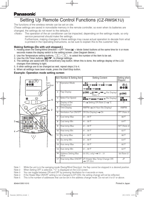
Setting Up Remote Control Functions (CZ-RWSK1U)The functions of the wireless remote can be set on site.(These settings are saved in nonvolatile memory in the remote controller, so even when its batteries are changed, the settings do not revert to the defaults.)<Note> The operation of the air conditioner can be impacted, depending on the settings made, so onlyservice personnel should make the settings.Furthermore, making changes to these settings may cause actual operation to deviate from whatis printed in the Operating Instructions, so be sure to explain this to the customer fully.Making Settings (Do with unit stopped.)1.2./, to select the number of the item to be set.3. 4. The settings are saved with the Once/Every Day button. When this is done, the settings display of the LCD changes from blinking to light.5. If other settings are to be changed as well, repeat steps 2 to 4.6. When all settings have been made, press the Start/Stop button.Example: Operation mode setting screenNote 1 While the unit is in the swinging mode (Swing/Wind Direction), the fl ap cannot be stopped in a desired position.Note 2 When Setting OFF is selected, “°C” is displayed on the LCD screen.Note 3 You can toggle between ON and OFF by pressing Ventilation for 4 seconds or more.Note 4 If the Heater Max ON/OFF setting is not changed to EP (ON), the setting change will not be refl ected.Note 5This is the number of addresses that can be set in the address change mode. Do not set it to 07 or above.14326Item Number85464159511010Printed in Japan。
爱莫特HLK6产品说明书

Eaton HLK6Eaton molded case circuit breaker accessory handle mechanism, Padlockable handle lock hasp, Frame J-K, RD-Frame breakersd, Series GGeneral specificationsEaton molded case circuit breaker accessory handle mechanismHLK67866795568876.6 in 2 in4.6 in 0.65 lb Eaton Selling Policy 25-000, one (1) year from the date of installation of the Product or eighteen (18) months from the date of shipment of the Product, whichever occurs first.Contact Manufacturer Product NameCatalog Number UPCProduct Length/Depth Product Height Product Width Product Weight WarrantyCompliancesFrame J-KUsed with RD-frame breakersd Series GPadlockable handle lock hasp RD-Frame breakers Application of Tap Rules to Molded Case Breaker Terminals Application of Multi-Wire Terminals for Molded Case Circuit BreakersCircuit breaker motor operators product aidPlug-in adapters for molded case circuit breakers product aidPower metering and monitoring with Modbus RTU product aidMotor protection circuit breakers product aidMolded case circuit breakers providing higher levels of selective coordination product aidMulti-wire lugs product aidComprehensive circuit protection for control panel applicationsCurrent limiting molded case circuit breaker module product aidHigh performance operating handles for Series G circuit breakers product aidCurrent limiting molded case circuit breaker module for series G, JG and CLSeries G MCCB quick selectorStrandAble terminals product aidBreaker service centersEaton's Volume 4—Circuit ProtectionMolded case circuit breakers catalogHandle Hasplock (Padlockable) for Series C R-Frame - ILFlex shaft handle installation tutorialEaton Specification Sheet - HLK6NG and ND-Frame molded case circuit breakersMOEM MCCB product selection guideFrame size Special features SeriesTypeUsed with Application notesBrochuresCatalogsInstallation instructions MultimediaSpecifications and datasheetsEaton Corporation plc Eaton House30 Pembroke Road Dublin 4, Ireland © 2023 Eaton. All Rights Reserved. Eaton is a registered trademark.All other trademarks areproperty of their respectiveowners./socialmedia。
罗克雷斯(RokRez)全面一站式套装说明书

Complete All-IN-One Kit IncludesRokRez Activator (x2) RokRez Base (x2) Decorative Chip (x2) Slip Resistant Additive (x2) Concentrated Cleaner (x2) Application Instructions Paddle Mixer 9” Roller Cover BrushDARK GRAYGRAYTAN432483/19QUESTIONS?866.515.8775Quick-Start GuideIMPORTANTREAD COMPLET E IN-DEPT H INST ALLAT ION GUIDE BEFORE OPENING OR USING PRODUCT.PLEASE FOLLOW THE INSTRUCTIONS CAREFULLY TO ENSURE PROPER APPLICATION FOR LONG-LASTING RESULTS.QUESTIONS?866.515.87751. Prep.2. Mix Kit.3. Apply kit.BrushPourRollMix CONCENTRATED CLEANER with 2 gal of water.Scrub floor with stiff broom and rinse thoroughly.*Allow to dry for 24 hours.Mix BASE , ACTIVATOR , AND OP T IONAL SLIP RESIST ANT ADDIT IVE inclean kit bucket, using the included Paddle Mixer— for 3 minutes .*Mix only 1-Base & 1-Activator at a time.12Broadcast43Trim/Edge Work—Use supplied brush to apply the mixed RokRez Solid epoxy.Paint around the edge of the entire surface, about 3” from walls.Using the Roller Cover (supplied) and a 9” Roller Frame, roll the poured ribbon of RokRez Solid epoxy evenly to distribute the coating over your first 4’ x 4’ section .*Roll in N-Shaped pattern *Back roll until evenPour mixed RokRez Solid epoxy from kit bucket in a thin 2” S-Shaped ribbon, covering your first 4’ x 4’ section .*Work in 4’ x 4’ sectionsBroadcast included Decorative Chip by tossing the chip into the air onto the wet coated 4’ x 4’ section.*Next to the uncoated concrete leave a 6”–12” area of wet RokRez Solid epoxy without Decorative chip added.his area will be rolled into when coating the next 4’ x 4’ section.Drying Time.*Cooler temperatures can slow down drying time.HEAVY ITEMS/DRIVE TIMEFOOT TRAFFIC18-24FULL CURE7。
伊顿 NRX 系列 Kirk Key 联锁装置操作说明书

NRX 系列Kirk Key 联锁装置的操作说明NRX 系列NF 类型壳架ANSI, UL1066, UL489 / IEC, IZMX16, IZM91NRX 系列RF 类型壳架IEC, IZMX40本手册适用于:警告(1) 只有具备电气资格的人员才能操作此设备。
(2) 如断路器不能被搬移至安全的工作地点,则务必始终断开一次和二次回路电源。
(3) 抽出式断路器需摇至断开位置。
(4) 所有断路器均需处于分闸状态,机械弹簧需释能。
若违反此说明手册中的这些程序,会导致人员伤亡或财产损失。
ƽ 警告应遵守本操作说明书及产品标签上规定的操作说明。
请注意以下五点安全规则:– 断电;– 确保装置不能意外重启;– 确保与电源隔离;– 接地及短路;和– 遮盖或为临近带电部件提供屏障断开设备电源。
在设备维修期间,仅可使用正规渠道获得的备件。
在维修和更换时,必须严格遵守规定的维修间隔及说明,以避免人身伤害及开关板损坏。
20211220116操作说明书2021年12月版NRX 系列Kirk Key 联锁装置的操作说明2伊顿公司 /electrical第1部分:基本信息钥匙联锁装置可将断路器固定在“OFF ”位置。
该装置安装在断路器的上部,并可通过前盖看到,钥匙锁由客户提供。
该装置具有以下安全功能:1. 没有钥匙时,断路器处于“断开”状态,不可合闸。
2. 钥匙在“ON ”位置(钥匙在锁芯内)且转动时,断路器可提供全部功能。
3. 断路器在“ON ”(闭合)状态时,钥匙不可拔出。
注:如要取下钥匙,首先按下断路器“OFF ”按钮,然后将钥匙逆时针旋转90度。
装置部件标识请参阅图1来直观识别下列部件:(A) 外保护环 (自粘式) (1个)(B) Kirk Keylock #KC40.10 (不提供Kirk Keylock) (C) 支撑垫圈 (1)个)(D) 金属安装支架 (1个) (E) 纤维保护垫圈 (2个)(F) M3 x 5mm 安装螺丝 (2个)(G) 大锁紧螺母 (1个) (不是装置的一部分,随钥匙锁提供)注:Kirk Keys 可能会一个Kirk Key 配两个大锁紧螺母。
- 1、下载文档前请自行甄别文档内容的完整性,平台不提供额外的编辑、内容补充、找答案等附加服务。
- 2、"仅部分预览"的文档,不可在线预览部分如存在完整性等问题,可反馈申请退款(可完整预览的文档不适用该条件!)。
- 3、如文档侵犯您的权益,请联系客服反馈,我们会尽快为您处理(人工客服工作时间:9:00-18:30)。
Unit106AFill in the blanks with the words given below. Change the form where necessary.register continuous retreat graduate boastemployment theory tremble dump outdoorspeculiar route harm contrary1. He should be polite enough not to ____ about what he has achieved.boast2. I pressed my parents until they finally gave in and ____ me for skating classes.registered3. They stressed the need for more ____ opportunities and better health care.employment4. Some questions seem obvious but others seem ____ and hard to answer.peculiar5. ____ exposure to sunlight is harmful to the skin.Continuous6. The university I ____ from with honors in 1998 is one of the best in China.graduated7. People who want to get rid of old cars sometimes ____ them in the woods.dump8. He doesn't ____ into self-pity because of his job as a trashman; instead, he feels proud of it as he thinks it is an essential task.retreat9. Michael won the competition, ____ to everyone's expectations.contrary10. When the boss told her she was fired, she was pale and ____ with shock.trembled11. It is therefore important that you take a ____ that is likely to succeed.route12. This ____ helps to explain how animals communicate with each other.theory13. I'm only trying to earn a bit of money. Where's the ____ in that?harm14. He wants to find a job which would not let him work ____.outdoorsFill in each of the blanks with a suitable preposition or adverb.1. Look me straight ____ the eye and say that you are not in any trouble.in2. You shouldn't worry about failing the exam—it's nothing to be ashamed ____.of3. She knows it will be hard to leave her boyfriend ____ because she has been with him many years.behind4. It's no use raging ____ the unpleasant situation you are in. Perhaps trying to do something tochange it may do you less harm.about5. ____ the sound of the car, the boy rushed out of the house to meet his father, who had promised to buy him a bike as a birthday gift.At6. It's disgusting to hear him boasting ____ his new car.about/of7. I love that pale blue wallpaper, but I don't think it would go ____ the carpet.with8. The Saturday afternoon flew ____, and before we knew it, it was over.by9. Don't look down ____ them just because they haven't passed the final exam.on10. The woman continued to yell ____ him though he had apologized.at11. As the author's ideas have been wrongly interpreted, the paper calls ____ a thorough revision.for12. He came back in as I was heading up ____ the shower. "Surprise, surprise," he said.to13. The guard had orders to stay ____ his post whatever happened.atFill in the blanks in the following passage by selecting suitable words from the Word Bank. You may not use any of the words more than once.I shouldn't have been surprised how tired I was after working a whole day in the factory. Each day I worked continuously assembling radios. It wasn't heavy work, but the repetition and standing for an entire day was difficult. At the end of the day, my legs __1__ from having stood in one place so long. We were supposed to get a rest outdoors every four hours, but __2__ we hardly ever were given the opportunity. The heat inside the factory was __3__ and many people often became ill. Although I did not become ill, my muscles often hurt wickedly near day's end. Besides, a sore body was nothing new to me. But, finding __4__ was not easy, so I stayed on. I tried to __5__ as little as possible. After many years, I was __6__ a job managing a small group of workers. I knew the job would be more stressful, but I agreed to try it anyway. During the __7__, I assisted another manager. After a few days, I started __8__ my group on how to do their work. They all had been my __9__ when I was an ordinary worker, so some of them refused to listen to me. I often had to __10__ at them so they would understand I was serious. The hardest day I ever had was when I had to fire one of them.1. trembled2. unfortunately3. intense4. employment5. complain6. offered7. trial8. coaching9. peers10. yellRead the following passage carefully and choose the best word or phrase to fill in each blank.Let's face it; young people entering the workforce today are lazy. I have heard just about (1) ____ complaint about today's workplace as I can take. (2) ____ to the view young people seem to have that things were better for (3) ____ generations, the fact is that there have never been so many great jobs for people wanting to enter the workforce. There are educational opportunities that have never existed before, and the standard of living is getting better all the time. Frankly, people who (4) ____ courage and commitment shouldn't blame (5) ____ but themselves for not taking the opportunities that are there for them.My first job was working as a trashman. I hauled trash for six years before I got (6) ____ to the position of manager. I wasn't (7) ____ of hard work. (8) ____ the day was finished, my shoulder would hurt, but I never (9) ____. I even assisted others and worked extra hours when I was needed. (10) ____, young people today seem to be lacking the same desire I had to work hard.I can boast that I never (11) ____ a job without being offered a better one. We can't all (12) ____ at the top. Most of us need to pay our dues and work from the (13) ____. After managing the small company for which I hauled garbage, I found a job with the city public works office (14) ____ a small department. Now, after 25 years of working in the garbage business, I manage all of the city's trash removal. Along the way I learned that a job well done is never (15) ____, and the person who does it will always (16) ____.Where is the "can do" (17) ____ that makes our country great? It doesn't (18) ____ what you do, as long as you work hard and do your best. Young people need to (19) ____ with finding a line of employment that needs them, and quit looking for perfection in their (20) ____ position. If work were supposed to be enjoyable, it wouldn't be called "work".1. as much2. Contrary3. prior4. lack5. anyone6. promoted7. scared8. By the time9. complained10. Unfortunately11. quit12. start out13. bottom up14. managing15. looked down on16. triumph17. attitude18. matter19. commence20. initialTranslate the following sentences into English.1. 爆炸后五分钟警察就到了车站,记者也到了。
