BST6800 西森隔爆型压力变送器
压力变送器说明书

防爆标志:隔爆型Exd IICT6,本安型Exia IICT6
防护等级:IP66
迁移特性:
正负迁移后,其量程上、下限不得超过量程的极限。
在最小量程时,最大正迁移为0.975URL;最大负迁移为-URL。
89MPa以下的变送器可承受压力范围:
14MPa(绝对压力)
MPa以下的变送器可承受压力范围:
30MPa(绝对压力)
两侧法兰可承受压力:60MPa
容积变化量:小于0.16cm³
阻 尼:0.1~32.0s(可调)
结构指标
隔离膜片:
316不锈钢、哈氏合金C、蒙乃尔合金、钽、镀金
排气/排液阀:316不锈钢、哈氏合金C、蒙乃尔合金
O型圈(与测量介质接触):氟橡胶、丁腈橡胶、乙烯-丙烯、聚四氟乙烯灌 充 液:硅油、惰性液
法兰和接头:316不锈钢、哈氏合金C、蒙乃尔合金
螺 栓:碳钢镀锌、不锈钢
电气壳体:低铜铝合金/316不锈钢
涂 层:内层导电氧化,外层聚酯环氧树脂
引压过程连接:法兰、接头1/2-1/4NPT(锥管螺纹)
电气连接:1/2-1/4NPT带螺纹端导线密封接头
重 量:3. 5kg(不包括选件)。
pmd70_pmd75_fmd76_fmd77_fmd78中文样本

技术资料 TI 382P/00/en
Deltabar S PMD 70/75, Deltabar S FMD 76/77/78 差压变送器
陶瓷和硅传感器的Deltabar S ,具有抗过载及监控功能,HART 、PROFIBUS PA 或 Foundation Fieldbus 通信协议
用途 Deltabar S 差压变送器用于下列测量任务:• 与一次元件结合,测量气体、蒸汽及液体的体积或质量流量
• 液体物位、体积或质量测量
• 差压监控,例如过滤器和水泵
优点
• 长期稳定性高
• 测量准确度高:最高可达 ±
0.075%,白金型:± 0.05% • 量程比 100:1,根据需要还可以更高 • 符合压力容器管理规程的要求 • 带HistoROM ® /M-DAT 储存模块 • 具备从测量传感器到电子组件的监控功能
• 差压、压力变送器的通用模块(从Deltabar S 到 Cerabar S ),例如: − 可互换的显示器
− 压力、差压变送器通用的电子组件• 快速设定菜单帮助实现快速投产 • 方便安全地通过 4...20 mA HART 、PROFIBUS PA 或 Foundation Fieldbus 总线,在菜单引导下进行现场操作 • 扩展的诊断功能
金属测量膜片和膜金属测量膜片和。
★MDM300.I.S★

英国密析尔MICHELL 仪表制造商露点变送器,dewpointmeters ,冷/冷镜湿度计,相对湿度传感器,过程水分测定仪,碳氢露点分析仪,液体分析仪中的水分和氧气分析仪,是一家国际领先的高精度传感与结束在该领域有30多年的经验。
我们的产品范围的高精度电容湿度传感器,帮助客户测量微量水分,在其过程中的应用,而我们的相对湿度变送器,相对湿度和温度传感器被广泛应用于HV AC 应用,药品储存等生产流程控制的环境条件是至关重要的。
,再加上我们的参考露点湿度计,湿度校准系统使客户能够进行校准便携式湿度计和相对湿度的仪器内部的,节省费用和停机时间。
我们提供高速测量中的应用范围,包括发电站,燃烧优化控制CO 2的水平啤酒厂,清洁气体的过程,如硅片生产和纯气体生成氧气。
天然气行业和发电厂的客户节省数百万美元的维修和停机时间,通过使用我们的康达迈科Condumax II 烃露点分析仪,以确保传输的天然气质量在贸易交接,防止燃气燃烧器故障,延长寿命过程的设备。
我们在烃类液体中的水分分析仪适用于防爆,本质安全和实验室版本,并允许范围广泛的烃类液体,包括变压器油,液压油,石油馏分和纯烃中的水分含量的连续测量。
一个高速的便携式露点仪,提供快速的现场检查在许多应用中,包括压缩空气,天然气和高电压开关淬气露点或水分含量测量。
这款轻巧,ATEX ,IECEx 认证,FM ,CSA ,GOST 认证产品比其他任何同类产品让更多的测量每工作小时。
硬质耐磨,但符合人体工程学的情况下和一个易于使用的接口,可以在恶劣的工业环境中的舒适和实际操作。
产品特点∙ 在低压下从T95至-60℃,小于15分钟时间反复快速的测量∙ 更高的压力测量成为可能 - 高达350巴 ∙ 电池寿命长:长达48小时的典型使用费用之间∙ 直观的应用套件,允许快速和简单的连接到您的采样点∙ 耐用,易于处理和操作:专为在工业环境中使用∙ 4-20 mA 外部设备输入变送器校准和验证∙ 轻量级:小于1.5公斤 ∙13点可溯源校准证书MDM300的MDM300采样选项MDM300 MDM300要获得最佳性能,它是为您的测量点有适当的样品调节至关重要。
贝思力 2020系列变压器温控器 说明书

安全指导在安装、操作和运行此温控器前,请仔细阅读本说明书,并妥善保管。
警告注意此温控器有危险电压,并监控危险的电力变压器。
如果不按本手册的规定操作可能会导致财产损失或人员严重受伤甚至死亡。
只有合格的技术人员才允许操作此温控器,在进行操作前,要熟悉使用手册中所有安全说明、安装、操作和维护规程。
本温控器的正常运行取决于正确的运输、安装、操作和维护。
1.此温控器的工作电源为: 220VAC ~240VAC ,50Hz/60Hz ; 2.请确保所有电气连接正确、牢固;3.此温控器接通电源后,请不要接触外露的带电部件; 4.端子L 、N 、1、2、3、4、5、6、7带有危险电压; 5.风机输出端子1、2、3、4、5、6与7间请勿短路;6.对变压器进行高压测试时,请先将温控器与传感器分离,以免损坏温控器!1.使用前请仔细阅读说明书;2.此温控器只能按本公司规定的说明使用,未经授权的修改和使用非本公司所出 售或推荐的零配件都可能导致本系统出故障,甚至失效;3.避免在含有二氧化硫(SO 2)、硫化氢(H 2S )或其他腐蚀性气体的大气中使用 本温控器,否则会使继电器触点失效;4.整机安装好后,连接好有关引线,在确定无误的情况下方可送电运行;5.传感器探头请勿用打火机烧烤(火焰温度在800℃左右); 6.不要在继电器输出触点上施加比最大额定值大的电压、电流;7. 当实际产品为特殊/定做产品时,若说明书内容与“9 特殊机型附页”内容相冲突时,以“9 特殊机型附页”内容为准。
8.请将使用说明书放在容易拿到的地方,并送给所有使用者。
目录1.产品概述 (1)2.产品型号 (1)3.技术参数 (1)4.产品功能介绍 (2)5.产品操作说明 (3)6.产品电气接线(以BWDK-3208BE为例) (6)7.通讯规约 (7)8.产品安装 (9)9.常见问题 (10)10.特殊机型附页 (10)1.产品概述此温控器是为风冷干式变压器设计的新一代温度控制器,它采用先进的计算机控制技术和数据存贮技术设计而成,且在设计中采用了硬件和软件相结合的抗干扰措施,使产品具有了极强的抗干扰能力。
深川变频S280系列防爆变频器机芯说明书

S280系列防爆变频器机芯使用说明书资料版本 V1.1归档日期 2022-08-30企业标准: Q/913703SSC002-2019山东深川变频科技股份有限公司为客户提供全方位的技术支持,用户可与就近的山东深川变频科技股份有限公司办事处或客户服中心联系,也可直接与制造商联系。
版权所有,保留一切权利。
内容如有改动,恕不另行通知。
总部:山东深川变频科技股份有限公司客户热线:400-812-8821技术支持:400-812-6621质量反馈:400-812-0778投 诉:400-812-6125网 址:目录S280系列防爆变频器机芯说明书目 录第1章 安全及注意事项 (1)1.1 安全事项 (1)1.2 注意事项 (1)第2章 技术指标及选型 (2)2.1 命名规则 (2)2.2 铭牌 (2)2.3 型号与技术参数 (2)2.4 技术规范 (3)2.5 S280‐FB系列厂用防爆变频器通用机芯产品外形图、安装孔位尺寸 (4)2.6 S280‐RG系列中压防爆变频器热管机芯产品外形图、安装孔位尺寸 (11)2.7 键盘的外形尺寸 (12)2.8 制动组件选型推荐 (13)第3章 电气安装 (14)3.1 外围电气元件选型指导 (14)3.2 主回路端子及接线 (15)第4章 键盘操作与显示 (18)第5章 功能参数简表 (20)第6章 重点功能参数详解 (40)第7章 通讯协议 (48)第8章 故障检查与排除 (51)8.1 故障信息与排除方法 (51)8.2 常见故障及其处理方法 (53)S280系列防爆变频器机芯说明书第1章安全及注意事项第1章 安全及注意事项1.1 安全事项1、应由电气专业技术人员安装、调试变频器,否则有触电危险!2、接线前请确认电源处于关断状态,否则有触电危险!3、接地端子必须可靠接地,接地电阻应小于0.1Ω!4、不能将输入电源连到输出端U、V、W,否则引起变频器损坏!5、确保配线导线线径符合技术标准,否则可能发生事故!6、变频器无须进行耐压测试,出厂时产品此项已做过测试,否则可能引起事故!7、上电后不要触摸变频器端子(含控制端子),否则有触电危险!8、若要进行参数自学习,请注意电机旋转中伤人的危险,否则可能引起事故!9、不要采用接触器通断的方式来控制变频器的启停,否则引起设备损坏!10、断开电源后因滤波电容上仍然有高压,所以不能马上对变频器进行维修或保养,必须等待5分钟以上后用万用表测母线电压((+)和(-)之间的电压)不超过36V才可进行。
SP-801-2型通用压力变送器说明书
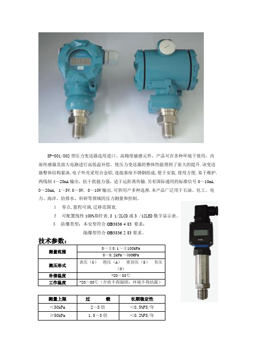
SP-801/802型压力变送器选用进口、高精度敏感元件,产品可在多种环境下使用,内部传感器及放大电路进行高低温补偿,使压力变送器的整体性能得到了很大的提升.该变送器整体结构紧凑,电子外壳采用合金铝,连接基座不锈钢组成,便于安装,使用方便,易于维护.两线制4~20mA输出,抗干扰能力强,适于远距离传输.另有国际通用的标准信号0~10mA, 0~20mA, 1~5V,0~5V, 0~10V输出,可供用户多种选择.本产品广泛用于石油、化工、电力、海洋、给排水、科研等领域的压力测量和控制。
1零点,量程可调,迁移范围宽.2可配置线性100%指针表,3 1/2LCD或3 /12LED数字显示表。
3防爆类型:本安型符合GB3836·4-83 要求;隔爆型符合GB3836·2-83要求。
注:具体参数可根据客户要求定制或见本产品出厂说明书.SP-801选型表注:型号,量程范围,测压形式,输出信号,接口尺寸,引线方式,供电电源为必选区。
现场显示,防爆类型为任选区。
负载:与供电电源有关,负载阻抗R与电源电压V的关系式为R≤50(V—12)Ω。
(工厂一般用24VDC供电,负载250Ω)注:带数显表头时,负载能力有所降低SP-802选型表注:型号,量程范围,测压形式,输出信号,接口尺寸,引线方式,供电电源为必选区。
现场显示,防爆类型为任选区。
负载:与供电电源有关,负载阻抗R与电源电压V的关系式为R≤50(V—12)Ω。
(工厂一般用24VDC供电,负载250Ω)注:带数显表头时,负载能力有所降低接线方式电路IC24VZS SP-801结构尺寸:·电子外壳:合金铝 ·主体结构:不锈钢 ·重 量:约1.0kg ·涂 层:塑料喷涂现场连线:Z---调零电位器 S---调量程电位器SP-802简易型结构尺寸主体结构:不锈钢重 量:约1.0kg电气连接注意:如无计量设备,请勿调节量程(S)电位器。
STA800中文产品说明书(VER.3)

手持组态工具 SmartLine变送器在操作员和பைடு நூலகம்送器之间采用双向的通
讯和组态功能。这是通过霍尼韦尔的适用于各种现场需求的 多协议通讯器(MCT202)实现的。MCT202能够现场组态DE 和HART变送器,它还可以在本质安全的环境下使用。所有 霍尼韦尔变送器经设计和测试符合所提供的通信协议,并且 可与任何经过验证的手持组态设备配合使用。
同类最佳的特性: ● 校验量程的精度高达0.055% ● 每年的稳定性高达0.015%/满量程 ● 自动静压和温度补偿 ● 高达100:1的量程比 ● 响应时间快达80ms ● 多种本地显示功能 ● 外部零位、量程和组态功能 ● 电源极性任意连接 ● 完善的自诊断功能 ● 基于ANSI/NFPA 70-202和ANSI/ISA 12.27.0集成双重密
模块化特性 ● 膜盒替换 ● 替换电子/通讯模块* ● 添加或卸除显示表头* ● 添加或卸除防雷端子模块* * 除了隔爆场合,现场更换可以在任何电气环境下进行(包括 本安场合),而不违反认证机构的规定。
霍尼韦尔独特的模块化特性可降低存库需求和整体工作 成本,而不会对性能产生影响。
STA800智能绝压变送器
运输和存放 ℃
-55 至 120
-55 至 120 -505至至110205
4
STA800智能绝压变送器
测量压力 (mmHgA)
25mmHgA (3.3KPaA)
额定工作区
硅油 DC200
回路 电阻 (ohm)
高温硅油 DC704
图例:
额定工作区 请联系霍尼韦尔 以获取特殊报价
注: 在高度真空下短时间 (70摄氏度时/1528小华时氏)暴度露时不2小会时) 导暴致露受不损会导致受损
负压隔离实验室装修改造用户需求URS说明书
负压隔离实验室装修改造用户需求(URS)说明书1. 项目简介本文件是描述罗欣药业(上海)有限公司(以下简称罗欣)负压隔离实验室装修改造的用户需求说明,供应商应根据本文件需求逐条做出响应,提供的技术要求应满足本文件需求的标准,如有偏差和不符合项应列出,并详细说明或提供解决方案。
2. 目的该文件是罗欣对项目范围的提出的期望功能和使用需求的说明,是图纸设计和设备选型的基本依据,是保证施工商提供的设计符合用户要求的标准,也是最终验收的依据。
经批准的用户需求标准将作为商务合同的附件,与合同具有同等的法律效力。
3. 范围该文件适用于罗欣公司负压隔离实验室装修改造的用户需求说明。
4.项目概述罗欣(上海)实验室,位于罗欣药业(上海)有限公司张江法拉第路85号,本次改造的区域为1号楼1212、1213、1216、1217房间,建筑地上六层(底层为G层),混凝土框架结构,火灾危险性为丙类,耐火等级二级,建筑面积105㎡,南北向7.7 米,东西方向13.7 米,层高3.9米,建筑总层高26.6米,功能设置为制剂小试研发,预计放置称量隔离器、设备隔离器、混合机、流化床、包衣机、压片机、胶囊充填机等,包衣和流化床放置区同时也是吸入制剂设备预留区;最大允许容纳实验人员4-6人,人流、物流、废物流分开,有合理的人流进出设计和物料进出设施;功能间有换鞋、更衣、缓冲间、物料准备间、洗衣间、清洗间等,设计应有合理的空调通风、装修材料和密闭负压设计,能够达到OEB4类高活性药品实验防护等级的要求;环境为一般区,温度:18~26℃;相对湿度:30% ~70%。
5.工程范围(1)、图纸优化设计:要求施工单位对本次发包平面图中相关部分进行优化设计,要求节能、合法合规,满足行业规范要求;(2)、工程施工范围:本次施工内容包含但不限于结构承重加固、装饰装修、暖通、电气、空调自控,所有安装为交钥匙工程,包工包料,甲方提供车间主要生产和实验设备,附设备清单及公用需求列表见附件;其他设备、材料由施工方提供。
FST600-205隔爆型温度变送器产品说明书
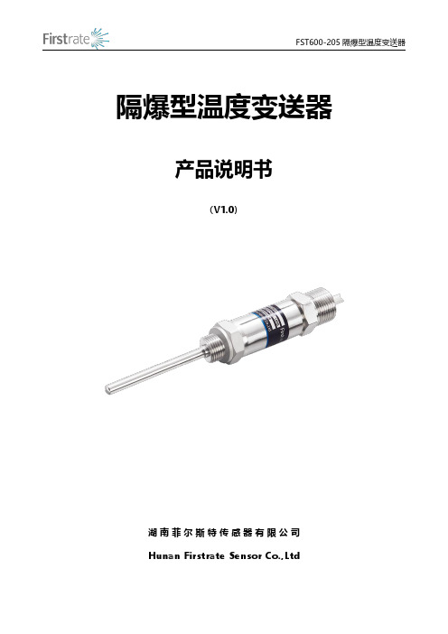
隔爆型温度变送器产品说明书(V1.0)湖南菲尔斯特传感器有限公司Hunan Firstrate Sensor Co.,Ltd●重要声明非常感谢您购买菲尔斯特传感器(变送器),我们为您真诚服务到永远。
菲尔斯特追求卓越不凡的品质,更注重良好的售后服务,如有问题,请拔打:400-607-8500(7×24h)。
操作错误会缩短产品的寿命,降低其性能,严重时可能引起意外事故。
请您在使用前务必仔细熟读本说明书。
将本说明书交到最终用户手中。
请妥善保管好说明书,以备需要时查阅。
说明书供参考所用,具体设计外形以实物为准。
●产品概述FST600-205防爆型工业通用温度变送器是由热电阻(偶)与温度变送器电路组成,采用二、三线制信号输出方式,带有非线性校正电路,可直接测量工业过程中的液体、气体介质和各种特质的温度将温度信号转换成与温度信号成性关系的电流4~20mA/电压0~5VDC、1~5VDC等信号输出,送显示仪表、调节记录仪表或计算机进行集散控制。
本产品广泛应用于石油、化工、冶金、电力、轻工、纺织、食品等行业,可与本公司生产的CH系列仪表及计算机等配套使用,组成各种温度测量控制系统。
FST600-205系列防爆型压力变送器的防爆性能符合《GB3836.1-2010爆炸性气体环境用电气设备第一部分:通用要求》及《GB3836.2-2010爆炸性气体环境用电气设备第二部分:防爆型“d”》的规定。
防爆型防爆标志为ExdIICT6Gb,适用与工厂内具有IIA、IIB、IIC级,T1-T6组成的可燃性气体或蒸汽以及空气形成的爆炸性混合物的环境中。
●原理概述FST600系列防爆型温度变送器是一种将温度变量转换成可传送的标准化输出的仪表,主要用于工业过程温度参数的测量和控制。
FST600系列防爆型温度变送器由两部分组成:传感器和信号转换器。
传感器主要由热点偶或热电阻;信号转换器主要由测量单元、信号处理和转换单元组成。
罗斯蒙特3051压力变送器产品说明书

产品说明书00813-0106-4001, Rev WE2023 年 4 月Rosemount™ 3051 压力变送器通过 Rosemount 3051 压力变送器,您将更有效地控制工厂,能够在众多压力、液位和流量应用中借助我们的产品,减少产品变化和复杂性,降低总拥有成本。
您将可以访问各种信息,方便您进行诊断、校正甚至防止出现问题。
以我们无与伦比的可靠性和丰富的经验打造的 Rosemount 3051 符合行业标准,可帮助您以更高的效率和安全性标准进行工作,从而保持全球竞争力。
Rosemount 30512023 年 4 月内容建立压力测量标准 (2)Rosemount 3051C 共平面压力变送器订购信息 (6)Rosemount 3051T 直连式变送器订购信息 (18)Rosemount 3051CF 流量计选择指南 (28)Rosemount 3051L 液位变送器订购信息 (62)技术规格 (74)Rosemount 3051 产品认证 (91)尺寸图 (92)选项外, (106)建立压力测量标准经实践检验的一流性能、可靠性和安全性■超千万装机量■参考精度为量程的 0.04%■安装总性能为量程的 0.14%■稳定性可保持在 URL 的 0.1% 长达 12 年■SIL 2/3 认证(IEC 61508)Coplanar ™平台增强安装和应用灵活性■通过集成的差压流量计、差压液位解决方案和一体化阀组提高可靠性和性能。
■安装方便,所有方案都全面组合,并经过渗漏测试和标定。
■丰富的产品满足您的应用需求。
高级功能Bluetooth ® 技术■提高生产力、可靠性和人员安全性。
无需高温作业许可。
无需攀爬储罐或建筑脚手架。
■快速组态、检修和排除故障,所有设备对技术人员触手可及,速度比传统 HART ® 连接快十倍。
诊断■回路完整性诊断将连续地监测电路,检测影响通讯信号的问题,并提供腐蚀、外罩进水或电源不稳定等警报。
西门子PASCAL CV 3110型压力变送器产品说明书
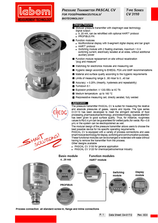
P RESSURE T RANSMITTER PASCAL CV T YPE S ERIES FOR FOOD /PHARMACEUTICALS /CV 3110BIOTECHNOLOGYSignal output::● 4..20 mA, can be retrofitted with optional HART ®protocol ●PROFIBUS PA ■Function modules●Multifunctional display with 5-segment digital display and bar graph●HART ®protocol●Switching module with 2 floating channels, maximum 1.5 Aswitching current, electrically isolated at all sides, without additional auxiliary power ■Function module replacement on site without recalibration "plug and measure"■Watchdog for electronics modules and measuring cell■Hygienic design according to EHEDG, FDA und GMP recommendations ■Material and surface quality according to the hygienic requirements ■Limits of measuring range 0...80 mbar to 0...40 bar ■Accuracy: < 0.25% (linearity, hysteresis and repeatability)■Turndown 5:1■Explosion protection: II 1/2G EEx ia IIC T6■Medium temperature up to 160 °C■Piezoresistive measuring cell, directly aerated, fully weldedThe pressure transmitter PASCAL CV is suited for measuring the relative and absolute pressures of gases, vapors and liquids. The type series CV3110 has been developed to meet the stringent demands of food processing, pharmaceutical technology, and biotechnology. Special attention has been given to good surface quality. Thus, for instance, roughness values to Ra 0.4 µm can be guaranteed for wetted parts (for welds: Ra < 0.8µm) or the system can be electropolished as well.The modular design of the pressure transmitter allows users to choose the best possible device for his specific operating requirements.PASCAL CV is equipped with a variety of process connections and uses smart module technology for display, switching and communication purposes.These functional modules can be exchanged or extended with ease without having to remove the transmitter from the process.Other designs available●PASCAL CV 3100 for general application●PASCAL CV 3120 for chemical/petrochemical industryProcess connection: all standard screw-in, flange and inline connectionsBasic modulePROFIBUSFunction modulesDisplay moduleHART ®-moduleSwitchingmodule4...20 mAData Sheet: D4-017/2P. 1Rev. 0D3Housing hygienic housing design with screw cap and windowMaterialhousing:stainless steel mat.no. 1.4301window:Macrolon gasket:NBR O-ringConstructiontwo-chamber system, minimum housing volume, excellent moisture and condensate protection Pressure compensation PTFE filter system Degree of protection EN 60529, IP 66Climatic category DIN EN 60721 3-4, 4K4HElectrical connection· screwed terminals 1 mm², cable entry fitting through screwing· circular plug connector M 12Weightstandard device without diaphragm seal and function modules approx. 0.65 kgHousing designConstruction welded designDiaphragm modifications see page 5 or order code Materialstainless steel mat.-no. 1.4404 or 1.4435see order codeSensor piezoresistive measuring element System fillfoodstuff oil FD1 (USDA-H1)according to FDAAmbient temperature -20 to 85°C Process temperature depending on design Allowed storage temperature -40...85 °CNote safety values as per examination certificate!Standard design 12....40 VDC Ex-proof design12....30 VDCInterference emission EN 50081 section 1Noise immunityEN 50082 section 2EU examination certificateII 1/2G EEx ia IIC T6Data Sheet: D4-017/2Housing design Measuring system Signal4...20 mA, two-wire,optional with HART protocol (not yet available)Current range 3.8 - 20.8 mA Current limitation approx. 22 mA Alarm state < 3.6 mA, optional > 21 mA Delay time approx. 160 ms measuring cycle 6 measurements / second Measuring range setting turndown 5:1Damping t 0.0 - 120.0 secondsLoadR <(Ohm)Limit point setting DIN 16086Reference conditions DIN EN 60770-1Calibration position vertical mounting position Linearity errors< 0.15% of span TD 5:1 no changeHysteresis < 0.05% of nominal range Repeatability < 0.05% of nominal range Influence of mounting position < 3.5 mbar Long-term drift < 0.1%/year of nominal range DIN EN 60770-1Temperature effecta)Lower range value / upper range value in range 0...60°C ± 0.15%/10 K of nominal range in range < 0°C, > 60°C ± 0.2%/10 K of nominal range b) process connection (diaphragm seal) depending on design flat diaphragm zero point error DN 25/1"4,8 mbar/10 K DN 32/1 1/2"2,3 mbar/10 K DN 401,6 mbar/10 K DN 50/2"0,6 mbar/10 K inline diaphragm zero point error DN 25/1"9,5 mbar/10 K DN 32/1 1/2"4,1 mbar/10 K DN 403,9 mbar/10 K DN 50/2"3,9 mbar/10 KThe specified zero error for the process connection is a guide value for a standard design. We can provide a detailed system calculation upon request. Systems with reduced diaphragm seal errors are also available.Temperature ranges OutputAccuracyApproval/testsP 0 t 2xt 3xt 4xt 5xte.g. damping t = 10 s = 50 s ~100 %windowsO-ring-seal electronicsfully encapsulated replaceablegasketsensor chamber fully encapsulated (reduced volume)plug connection cable entry fitting U - 12 V 22.5 mA^Process connection separate terminal compartment (reduced volume)terminalspressure sensor with direct connection to atmosphericpressure compensationatmospheric pressurecompensationP. 2100 %63 %Supply limits of measuring range meas. span nominal range: e.g. 1 barData Sheet: D4-017/2Display module (multifunctional display) optional·Module housing made of ABS, encapsulated electronics unit·Many operating mode menus ·5-segment pressure read-out with unit ·Read-out display-pressure (standard)-percent -current-sensor temperature·Bar graph 36 segments = 0...100%·Measuring circuit test (current sensing function)3.55...22.0 mA·Alarm indicator on display·Switching function indicator (with switching module)Switching module, optional·No additional auxiliary power required ·Module housing made of ABS, encapsulated electronics unit · 2 limit values, voltage free, short-circuit-proof ·Switching capacity 50 V DC / 500 mA (Ri < 1.5 Ω)or 30 V DC / 1.5 A (Ri < 0.3 Ω)·Overload indicator: LED red, overload or short-circuit ·Fusible cut-out at overload /short-circuit with automatic reset ·Switch points: 0.0 - 100.0% adjustable Standard: 50.0%·Switching function: maker or breaker, adjustable Standard: breaker ·Device off circuit: contact open ·Hysteresis: 0.0% to 100.0%, adjustable standard: 0.1%falling or rising, adjustable,standard: falling ·Switching rate: 6 Hz·Electrically isolated to all sidesInsulation voltage: 500 V, 2.5 kV/2 sec.·Electrical connection: terminal blocks 1 mm²pluggable with automatic module detection - plug and measure -P. 3Profibus module description and HART ® connection upon request ^pluggable with automatic module detection - plug and measure -Basic module: 4...20 mAData Sheet: D4-017/2Switching modulex = configurable w = factory settingP. 4Data Sheet: D4-017/2Mounting positionHousingProcess connectionsP. 5(short term up to 140°C, 1h)Modifications reservedData Sheet: D4-017/2P. 6- please give additional specifications for models not listed -LABOM Mess- und Regeltechnik GmbH Postfach 12 62 D-27795 Hude Tel. (04408)804-0 Fax: (00408)804-404。
细述电容式压力变送器与扩散硅压力变送器区别

电容式压力变送器与扩散硅压力变送器区别压力变送器可分为:电容式压力变送器与扩散硅压力变送器。
电容式压力变送器:电容式压力变送器自20世纪80年代诞生至今己有20多年历史,由于它精度高,耐腐蚀,耐污染,稳定性好,是冈内外公认的检渊低真空压力的理想仪表。
美国的M.K.S公司是全球生产电容式压力变送器的主要生产厂家,涉及民用工业的各个领域,并在航天工业、核工业等军事工业中发挥着独特的作用。
这种压力变送器是利用弹性薄膜在压差作用下产生压变引起电容变换的原理制成的,它由检测部分和转换电路组成,.检测部分有真空腔和检测腔两个腔体。
真空腔为全密封结构,经质谱检漏仪检漏合格后,通过长时间排气,最后将排气管密封而形成,井备有消气剂以消除残余气体,长期保持高真空.固定极板位于真空腔中,由极板引出线引至腔外.检测膜片置于高真空的真空腔及连接低真空待测系统的检测腔之间,检测膜片为可动极板,其与固定极板形成一个平板电容器,有一定的电容(J.。
被测的低真空压力通过检测孔进人检测腔,检测膜片产生挠曲,改变了其与固定极板的距离,电容值也随之改变。
不同的低真空压力值决定不同的电容值。
最后电容信号被输送到电路转换部分,电路转换部分将电容信号通过变换、整理、放大等环节,输出一个标准电压或电流信号,它与真空压力成正比。
该类型压力变送器为高灵敏度差压测量,零点稳定。
动态响应特性好,适应性强,一般适用于静压力的测最.扩散硅压力变送器:20世纪90年代中期,美国Icscnsor,公司,Nova公司应用硅品石和硅品片益合两项尖端科技生产了新型扩散硅压力传感器并开发出具有精度高、重复性小、抗腐蚀的扩散硅压力变送器过程压力通过隔离膜片、密封硅油传输到扩散硅膜片上,同时参考端的压力(大气压)作用于膜片的另一端。
这样膜片两边的压差产生一个压力场,使膜片的一部分压缩。
另一部分拉伸,在压缩区和拉伸区分别有两个应变电阻片,以感受压力引起的阻值的变化,从而将压力信号转换为电信号.扩散硅在低温零度以下、高温85℃以上难以正常使用,也不适用于20MPa 以上的高压。
中控CJT型变送器说明书
CJT 型电容式智能压力变送器适用于石油、电力、化工、冶金、制药、轻工等行业中的压力、流量和液位测量等众多 场合。
特点
支持 HART 协议 模块化设计 带非易失性 EEPROM 外壳防护等级达到 IP65
无机械传动部件,坚固耐振
抗单向过载能力强
精确度等级 0.1 级,量程比 40:1 通过就地按键即可调整量程和零点 具有自诊断和远程诊断功能 结构小巧、重量轻、体积小、方便安装 可使用于各种腐蚀介质场合 安全防爆
2.电子线路部分
微处理器: 微处理器控制变送器的运行,对压力敏感元件通过振荡电路和温度传感器对其工作压力和工作介质温度进行检测。微
处理器利用传感器特征化 EEPROM 中的数据进行线性化处理和补偿运算,计算出工作介质的压力值,并送往数/模转换器 和 HART 通信部分。 数/模转换器:
数/模转换器将微处理器修正后的压力数字信号转换为(4~20)mA 模拟信号送往输出回路。 HART 通信:
量程、测量范围和过压极限
量程代码
3 4 5 6 7 8 9 0
量程(kPa)
最小
最大
0.75
7.5
0.935
37.4
4.67
186.8
17.24
690
51.7
2068
172.25 6890
517
20680
1034.2 41370
测量范围(kPa)
下限
上限
-7.5
7.5
-37.4
37.4
-100
186.8
代码
22 23 2A
结构材料 法兰接头 排气排液阀 隔离膜片 316 不锈钢 316 不锈钢 316L 不锈钢 316 不锈钢 316 不锈钢 哈氏合金 C 316 不锈钢 316 不锈钢 316L 不锈钢
安德森仪器公司RSP卫生电子压力变送器说明书
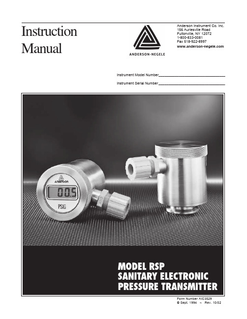
Anderson Instrument Co. Inc. 156 Auriesville Road Fultonville, NY 120721-800-833-0081Fax 518-922-8997www.and erson-negele .comInstructionManual © Sept. 1994 ~ Rev. 10/02Instrument Model Number_________________________________Instrument Serial Number _________________________________MODEL RSPP AGE2SECTION 1 - INTRODUCTION31.1 SPECIFICATIONS3SECTION 2 - THEORY OF OPERATION5SECTION 3 - INSTALLATION5SECTION 4 - SENSOR WIRING6SECTION 5 - INSTRUMENT WIRING75.1 LOOP POWER7SECTION 6 - LIQUID CRYSTAL DISPLAY86.1 LCD INSTALLATION8SECTION 7 - MAINTENANCE8SECTION 8 - CALIBRATION98.1 CALIBRATION OF TRANSMITTER98.2 CALIBRATION OF LCD DISPLAY9SECTION 9 - TROUBLESHOOTING129.1 VOLTAGE CHECK129.2 CURRENT CHECK129.3 MISCELLANEOUS TROUBLESHOOTING12SECTION 10 - WARRANTY AND RETURN STATEMENT13FIGURES1Dimensional View32Wiring Terminal Connections63Loop Power Guidelines74Loop Diagram75LCD Display Calibration Adjustments10P AGE3 Section 1 - IntroductionThis manual has been designed to assist the end-user with the installation of the Andersonmodel RSP Sanitary Electronic Pressure Transmitter. When followed properly, your sensorwill provide optimum performance with minimum maintenance.FIGURE 1 - Dimensional View1.1 SPECIFICATIONSExcitation:9-32 VDC (Absolute), 24 VDC Nominal, regulated orunregulated14-37 VDC (Absolute) with displayOutput:4-20 mA DCLoop Resistance:0-750 ohms at 24 VDC0-1050 ohms at 30 VDCIndication:Optional, 3 1/2 digit, .5" high LCD, cap mountedAccuracy:±.5% of span, full scale, for standard ranges, rangesbelow 0-50 psig±1% full scale; all compound and psia ranges,±1.5% full scaleOver-Range Rating: 2 times base rangeStability:±0.3% of calibrated range/6 monthsStorage Temperate:-40 to 150°F (-40 to 65°C)Zero and Span Adjustment:±10% of rangeRepeatability:±.3%P AGE 4Hysteresis:± .2%Process Temp. Range:20° to 225°F (up to 300°F if horizontal mount)Process Temp. Effect:Less than 0,2% of full scale output/10°F change Ambient Temp. Operating Range:0° to 120°F (-17.8° to 48.9°C)Storage Temperature:-40° to 149°C (-40° to 65°C)Mounting:Direct connection Housing Material:304 Stainless Steel Wetted Parts:316L Stainless Steel standard; Hasteloy "C" diaphragm optionalSurface Finish (wetted parts):R a = 25 microinches (.6 microns) for standard finish;R a max = 8 microinches (.2 microns) for electropolished fittings (specify when ordering)Recommended Cable:18-24 AWG, foil shielded, and PVC coated.(3/16" - 1/4" O.D. insulation)Wiring Connection:Screw Terminal; Accessible via removable screw capconduit housingP AGE5 Section 2 - Theory of OperationThe Anderson RSP Pressure Transmitter can be utilized for applications in which a processvariable of pressure must be converted to an electronic signal. This unit utilizes an internalpressure transducer to convert the process measurement into a corresponding mV signal.The mV signal then passes through custom linearization and conditioning circuitry. Theresulting signal is an industry standard 4-20 mA. This mA signal is factory set over thespecified range of the unit. From here the signal may be sent to an Anderson Digital Display,Microprocessor based controller, chart recorder, or customer supplied instrumentation. Inaddition, the RSP may be supplied with an integral LCD display for readout directly at theprocess.Section 3 - InstallationThe physical installation is the most important concern with regards to promoting sensorreliability. Sensors must be installed in such a way that the housing and cable are not subjectto physical abuse. In addition, moisture or moist air must not be allowed to enter the sensorhousing or cable.NOTE: The installer assumes responsibility for preventing water or water-vapor from enteringthe sensor housing.Your new RSP transmitter is supplied with a conduit housing. If mounted horizontally, theconduit connection should point downward. Also, to prevent entry of excessive moisture, it ishighly recommended that flexible conduits not be connected directly to the sensor. If conduitis to be run to the sensor, it is preferable that the watertight connector provided with eachsensor not be removed from the sensor. Instead, run the flexible conduit as near to thesensor as possible and utilize a seal-tight connector at the end of the conduit. Allow a shortamount of cable to run between the sensor and the flexible conduit. This isolates the sensorhousing from the conduit system and any moisture it may contain. If the conduit is connecteddirectly to the sensor, the chances are high that the sensor will eventually fail due to exces-sive water or water vapor entry into the housing.NOTE: It is recommended that a sensor "ZERO" be performed at time of installation. Refer tosection 8.1, page 9 for information on this procedure.P AGE6Section 4 - Sensor WiringAnderson recommends a cable of 24 gauge, 4 conductor, shielded (Belden #9534) orequivalent. Four conductor cable is utilized because of its roundness, which provides asuitable seal when used with seal-tight connectors, strain reliefs and rubber grommets.Irregular shaped cable does not allow for a watertight seal.If utilizing customer supplied cable, select a round cable with 22-24 AWG wire and a shield.In order for the Anderson provided seal-tight connector to seal on the cable, the O.D. of thecable must be between 3/16" and 1/4". If smaller cable is utilized, a different neoprenebushing must be used (must be customer supplied).If an alternate seal-tight type connector is going to be used, be absolutely certain that therubber bushing will adequately seal on the cable. Do not use a connector intended for powercable (large inside diameter) if the sensor cable is only 1/4". Be sure to use Teflon threadtape when attaching the new seal-tight connector.Wiring to the conduit housing sensors is accomplished as follows:1. Remove the housing cap to expose the wiring terminal block.2. Insert the cable through the seal-tight connector, stripping back approximately 2 inches ofsheathing to expose the wires.3. Two wires will be utilized for connections at the transmitter end of the loop. Normal colorcodes being RED (Loop +) and BLACK (Loop -). Trim off all unused wires, including thebare shield ground wire. To prevent a GROUND LOOP condition, be sure the shieldmaterial and the shield ground wire do not touch the sensor housing. Use an insulatorsuch as electrical tap or heat shrink tubing if necessary.4. Strip the tips of the remaining wires back approximately 3/8 of an inch and twist strands(tinning is highly recommended).5. Using Figure 2, make the proper connections to the wiring terminal strip (located inside theconduit housing)Figure 2 - Wiring Terminal ConnectionsP AGE7 Section 5 - Instrument WiringWith the proper wiring connections made at the senor end of the loop, it is now time to makefinal connections at the instrument end of the loop. The RSP may feed instruments such asAnderson digital display, microprocessor based controllers, chart recorders, or customersupplied instrumentation.5.1 LOOP POWERThe Anderson RSP requires loop power for operation. Ratings are as follows:Standard RSP Transmitter:9-32 VDC (Absolute), 24 VDC Nominal, regulated orunregulatedRSP Transmitter with LCD Display:14-37 VDC (Absolute), 24 VDC Nominal, regulated orunregulatedAs inherent resistance associated with cable length and signal receiver input may affectoperation of the transmitter, Figure 3 shows some guidelines for loop power required.FIGURE 3 - Loop Power GuidelinesPlease consult the Installation/Service Manual that was provided with your receiver forspecific wiring instruction. Most Anderson receiver (displays, chart recorders, etc.) arecapable of supplying loop power. Typical wiring would be as follows:Figure 4 - Loop DiagramP AGE8Section 6 - Liquid Crystal DisplayThe RSP transmitter is available from the factory, or field upgradeable, with an integral LCDprocess display. The display is supplied from the factory pre-calibrated to the specifiedparameters.NOTE: Although re-calibration may be performed, no alteration to the decimal point locationmay be made - this is a factory set function.6.1 LCD INSTALLATIONInstallation of an LCD Process Display into an already existing RSP transmitter is as follows:1. To prevent possible damage to the transmitter or receiver, it is recommended that allpower be disconnected before proceeding.2. Remove the conduit cap from the sensor. If upgrading a RSP in the field, you will besupplied with a new conduit cap (hole in center).3. To the left of the wiring terminal block will be a small YELLOW wire loop. It has an arrowpointing to it stating "WITH DISPLAY CUT". Cut this loop, making sure the two ends don'tcome in contact with each other or anything else.4. Insert the LCD RED wire into the (DISP +) terminal and tighten.5. Insert the LCD BLACK wire into the (DISP -) terminal and tighten.6. Slide the LCD display into the end of the conduit housing, orienting for proper position.7. Secure the new cap provided.8. Apply power to the system.,9. At this point, check to be sure you are getting a proper reading If the display is not active,immediately power down the loop and check you connections. If you feel the display is notreading properly, it may be necessary to perform calibration to the transmitter. Refer toSection 8 - Calibration.Section 7 - MaintenanceAnderson electronic sensors require very little maintenance, if any. We suggest that thesensor be inspected at 6 month intervals to ensure that they are not being physically abuse,moisture is not entering the housing, and that the wiring is sound.P AGE9 Section 8 - CalibrationIf you feel that the output of the RSP transmitter is not correct, calibration of the unit may berequired. Section 8.1 illustrates the pro procedures for calibration of the transmitter, withsection 8.2 covering calibration of the LCD display.Equipment required:Pressure sourceAccurate reference gaugeDC Milliamp Meter (accurate to .01 mA)Small straight blade screwdriverCalculatormA Signal generator (helpful for LCD calibration)8.1 CALIBRATION - TRANSMITTERAdjustments to the transmitter are made via the "ZERO" and "SPAN" potentiometers. Thesetwo adjustments are non-interactive, meaning changing the zero will not change the span. Asgeneral maintenance to the unit, a zero check is recommended at approximately 6 monthintervals. If your unit is calibrated at a compound range, you will not see 4.00 mA at atmo-spheric zero. As reference, you may use the following chart to determine if your unit mayrequire calibration (most common ranges are shown).The output of a properly calibrated transmitter may be calculated by using the followingformula:NOTE: The transmitter should be wired in a complete loop at this point, or on a test benchand configured per the diagram shown in Figure 4, page 7. Although no interaction betweenzero and span occurs, when making adjustments you should be as close to the top andbottom transmitter range as possible. This will ensure the best possible linearity in the finalsignal output.1. Expose the transmitter to a known zero reference point. If transmitter range starts atatmospheric zero, zero adjust at atmospheric zero. If transmitter is a compound range,you should be as close to sensor zero as possible . You must calculate the expected mAsignal (use formula proved at start of this section).2. Remove cap from transmitter.3. With your meter set to DC mA, connect the RED (Meter +) lead to the (DISP +) terminal.Connect the BLACK (Meter - ) lead to the (DISP -) terminal.4. DO NOT USE THE LCD TO MAKE INITIAL SENSOR ADJUSTMENTS. If the LCD is notin calibration, an error will result in the calibration of the transmitter. The LCD should becalibrated separately. See Section 8.2, page 10 for proper procedures.5. Adjust the transmitter ZERO potentiometer as shown in Figure 2, page 6, until you eitherP AGE10see 4.00 mA if you are at atmospheric zero, or your expected mA signal for a compoundrange.6. Expose the transmitter to a know process variable near the top end of the range.7. Again, using the formula provided, calculate the mA reading expected.8. Adjust the transmitter SPAN potentiometer, as shown in Figure 2, page 6, until you seeyour expected mA output.NOTE: For pressure transmitters with compound ranges, the ranges must first be convertedto all one type unit of measure. For example, a 30" Hg - 0-30 psig unit may be considered tohave a range of -14.7 psig - 0-30 psig and a span of 44.7 psig (2.036" Hg = 1 psi). Be carefulnot to lose the (-) sign while performing the calculation of the proper reading.8.2 CALIBRATION OF LCD DISPLAYNOTE: Be sure the transmitter is in calibration before attempting to adjust the LCD display.The LCD reading is based on mA output from the transmitter. Therefore, if the transmitter isout of calibration, this error will be reflected in the LCD reading.To perform calibration of the LCD display, you must first determine the Zero and Span. Thisinformation is on a sticker located on the back of the display. Adjustments are made via Zeroand Span potentiometers, see Figure 5 for location. You may use either the RSP transmitteritself to perform calibration of the display, or a 4-20 mA signal simulator.Figure 5 - LCD Display Calibration AdjustmentsCALIBRATION OF LCD USING 4-20 mA Simulator1. Disconnect he LCD display from the transmitter by removing the RED and BLACK wiresfrom their respective terminals.2. Attach the POSITIVE lead of the simulator to the RED lead of the LCD display, and theNEGATIVE lead of the simulator to the BLACK lead of the LCD display.3. The simulator should be set to POWERED output mode so that loop power is supplied. Ifyour simulator is not capable of this function, wire to 9 VDC batteries in series with the4-20 mA simulator and the LCD display.4. Apply 4.00 mA to the LCD display.5. Adjust the ZERO potentiometer until he LCD matches the range indicated on the sticker inthe spot labeled ZERO CALIBRATION.P AGE116. Apply 20.00 mA to the LCD display.7. Adjust the SPAN potentiometer until the he LCD matches the range indicated on thesticker in the spot labeled SPAN CALIBRATION.8. The LCD display is now properly calibrated. Re-wire the transmitter at this time.CALIBRATION OF LCD USING TRANSMITTER/PROCESS1. To complete this calibration, you must have a pressure source and a known accuratereference. At this point you MUST be certain that the transmitter is in proper calibration.If necessary, start with section 8.1 - Transmitter Calibration, page 9.2. Expose the transmitter to a know pressure near the LOW end of the calibrated range.3. Adjust the potentiometer on the back of the LCD display labeled ZERO until the displaymatches your know reference4. Expose the transmitter to a known pressure near the HIGH end of the calibrated range.5. Adjust the potentiometer on the back of the LCD display labeled SPAN until the displaymatches your know reference6. The LCD display is now properly calibrated.P AGE12Section 9 - Troubleshooting9.1 VOLTAGE CHECKUsing a digital multimeter on the DC volts scale and with the sensor connected to thereceiver, confirm that the sensor is being provided the correct loop power. Place the RED(Meter +) lead on the (Loop +) terminal, and the BLACK (Meter -) lead on the (Loop -)terminal. You should see between 9-32 VDC for a standard transmitter, and between 14-37VDC if you have an optional LCD display installed.9.2 CURRENT CHECKTo check the mA loop, be sure the sensor is connected to the receiver. Open the cap on thetransmitter to expose the wiring terminals. Using a digital multimeter on the mADC scale,connect the RED (Meter +) lead to the (DISP +) terminal and the BLACK (Meter -) lead to the(DISP -) terminal. You will be reading the mA current loop. A high current flow, approaching30 mA, indicates a problem with the transmitter (internal source). If no current flow isobserved this indicates either an open loop or a problem with the transmitter. To check atransmitter at a know pressure, refer to the Calibration section for information on how toproperly calculate the mA output at the known value.9.3 MISCELLANEOUS TROUBLESHOOTINGSymptom ActionNo display on receiver• Check loop for broken wire• Check receiver for power out (loop power)Display on receiver reading improperly• Perform calibration check on RSP• Perform calibration check on signal receiver Transmitter not operating after LCD• Place a wire jumper from (DISP +) terminal toremoved (DISP -) terminalWhen testing Loop, NO current flow• Check for broken connectionsdetected• Check loop wiring (incorrect polarity affectsloop)Feel free to contact Anderson Technical Services Department at 1-800-833-0081 for furtherassistance with troubleshooting.P AGE13 Section 10 - Warranty and Return StatementThese products are sold by The Anderson Instrument Company (Anderson) under thewarranties set forth in the following paragraphs. Such warranties are extended only withrespect to a purchase of these products, as new merchandise, directly from Anderson or froman Anderson distributor, representative or reseller, and are extended only to the first buyerthereof who purchases them other than for the purpose of resale.WarrantyThese products are warranted to be free from functional defects in materials and workman-ship at the time the products leave the Anderson factory and to conform at that time to thespecifications set forth in the relevant Anderson instruction manual or manuals, sheet orsheets, for such products for a period of one year.THERE ARE NO EXPRESSED OR IMPLIED WARRANTIES WHICH EXTEND BEYONDTHE WARRANTIES HEREIN AND ABOVE SET FORTH. ANDERSON MAKES NOWARRANTY OF MERCHANTABILITY OR FITNESS FOR A PARTICULAR PURPOSEWITH RESPECT TO THE PRODUCTS.LimitationsAnderson shall not be liable for any incidental damages, consequential damages, specialdamages, or any other damages, costs or expenses excepting only the cost or expense ofrepair or replacement as described above.Products must be installed and maintained in accordance with Anderson instructions. Usersare responsible for the suitability of the products to their application. There is no warrantyagainst damage resulting from corrosion, misapplication, improper specifications or otheroperating condition beyond our control. Claims against carriers for damage in transit must befiled by the buyer.This warranty is void if the purchaser uses non-factory approved replacement parts andsupplies or if the purchaser attempts to repair the product themselves or through a third partywithout Anderson authorization.ReturnsAnderson’s sole and exclusive obligation and buyer’s sole and exclusive remedy under theabove warranty is limited to repairing or replacing (at Anderson’s option), free of charge, theproducts which are reported in writing to Anderson at its main office indicated below.Anderson is to be advised of return requests during normal business hours and such returnsare to include a statement of the observed deficiency. The buyer shall prepay shippingcharges for products returned and Anderson or its representative shall pay for the return ofthe products to the buyer.Approved returns should be sent to:ANDERSON INSTRUMENT COMPANY INC.156 AURIESVILLE ROADFULTONVILLE, NY 12072 USAATT: REPAIR DEPARTMENTANDERSON INSTRUMENT CO., INC • 156 AURIESVILLE RD. • FULTONVILLE, NY 12072 • USA • 800-833-0081 • FAX 518-922-8997 ANDERSON INSTRUMENT CO. LP • 400 BRITANNIA RD. EAST, UNIT 1 • MISSISSAUGA, ONTARIO L4Z 1X9 • CANADA • 905-568-1440 • FAX 905-568-1652 NEGELE MESSTECHNIK GmbH (A Division of Anderson) • RAIFFEISENWEG 7 • D-87743 EGG A. D. GÜNZ • GERMANY • +49 (0) 8333/9204-0 • FAX +49 (0) 8333/9204-49。
西森法兰式压力变送器参数

输出信号 2 线制,4~20mADC HART 输出,数字通讯,HART 协议加 载在 4~20mADC 信号上。 输出信号极限:Imin=3.9mA,Imax=20.5mA
1
报警电流(模式可设置) 低报模式(最小):3.6 mA 高报模式(最大):21 mA 不报模式(保持):保持故障前的有效电流值 报警电流标准设置:高报模式
5、响应时间
放大器部件阻尼常数为 0.1s;传感器和液位法兰 时间常数为 0.2~2s,取决于量程及量程比。附加 的可调时间常数为:0.1~60s。
6、一般条件
6.1 安装条件 通过液位法兰变送器可直接固定于任何位置。最佳 状态是使过程法兰轴处于垂直状态,位置偏差将产 生可校正的零位偏移。电子表壳最大可旋转 360°,定位螺钉可将其固定于任何位置。 6.2 环境条件 环境温度 最 低:取决于填充液 最 高:85℃ 带液晶显示、氟橡胶密封圈时 -20~65℃ 储存温度/运输温度 最 低:取决于填充液 最 高:85℃ 相对湿度:0~100% 抗冲击 加速度:50g 持续时间:11ms 抗震动:2g 至 500Hz 电磁兼容性(EMC) 见下页表 3《电磁兼容性附表》 6.3 过程介质极限 介质温度极限:-30~180℃ 变送器本体压力极限 从 3.5kPa 绝对压力至额定压力,保护压力可大于
不锈钢表壳可选
外壳密封圈:丁腈橡胶(NBR)
铭
牌:不锈钢 304
电气连接
M20X1.5 电缆密封扣,接线端子适用于 0.5~2.5mm2 的导
线。
2
·过程连接 变送器低压侧有 UNF 7/16``内螺纹。变送器高压 侧的液位法兰符合 ANSI 标准或 DIN 标准。可直接安装,参考尺寸图。 外壳防护等级:IP67
SIEMENS SITRANS P压力测量仪表 说明书

! 200412压力测量仪表产品一览应用说明目录页参数化软件用于压力和绝压测量的二线制变送器SITRANS P ,Z 系列 微型单量程变送器模拟电子部件,可以库存交货3–用于压力测量的二线制变送器SITRANS P ,MPS 系列(潜水式传感器)用来测量井、储油罐、隧道、堤坝等的液位6– 用于压力测量的二线制变送器SITRANS P ,MK II 系列 量程比:4.5:18–用于压力测量的二线制变送器SITRANS P ,MS 系列 量程比:30:1使用2个按键通过HART 协议进行参数化12SIMATIC PDM二线制变送器,用来测量: • 压力 • 绝压• 差压和流量 • 液位SITRANS P ,DS III 系列 SITRANS P ,DS III PA 系列 量程比:100:1 参数化:• 对 DS III 系列,使用3个按键通过HART 协议进行参数化• 对DS III PA 系列,使用3个按键和PROFIBUS-P A 进行参数化 可以库存交货17 36SIMATIC PDM SIMATIC PDM二线制变送器用于4线制连接时的适配辅助电子部件输出:0 或 4 至 20 mA 电源:AC/DC 24 V ,AC 230 V57–用于粘性、腐蚀或纤维介质(以及极端温度介质)压力测量的远传密封组件对夹式和法兰设计的远传密封组件 用于食品工业的快装式远传密封组件 可提供宽量程膜片材料和填充液64–用于食品、医药和生物技术的压力和绝压变送器SITRANS P 紧凑型变送器 双线或三线系统的单量程变送器符合EHEDG ,FDA 和 GMP 规则,基于卫生学设计的各种无菌连接件83–断开介质和差压管路 在阀组或断流配件上安装的变送器提供钢、黄铜或不锈钢制的各种接头和阀组 提供用于SITRANS P 变送器的各种过程连接的阀组91–3压力测量仪表SITRANS P 压力和绝压变送器Z 系列图1 7MF1562和 7MF1563 压力变送器变送器7MF1562 用来测量气体、液体和蒸汽的相对压力;变送器 7MF1563 用来测量液体和气体的绝压和相对压力。
天康集团(压力变送器)选型样本

存贮器中。变送器掉电后,数据仍保存,故而上电后变送 器能立即工作。
数/模转换与信号传送 过程变量以数字式数据存贮,可以进行精确地修正和 工程单位的转换。信号经修正后的数据转换为模拟输出信 号。HART手操器可以直接以数据信号方式存取传感器读 数,不经过数/模转换以得到更高精度。
三、产品说明
传感膜头 3051C型采用先进技术及生产线制造的高品质传感 器。传感器与过程介质和外部环境保持机械、电气及热隔 离。传感器远离过程法兰,移至电子外壳的颈部,可实现 机械隔离和热隔离。该设计使传感器不与过程热源直接接 触,并释放了传感器杯体上的机械应力,可提高静压性 能。 玻璃密封的压力输送管与传感器杯体绝缘安装,保证 了电气绝缘,可提高电子线路的灵活性、性能与耐瞬变电 压保护的能力。 3051C型传感膜头还进行温度测量,用于补偿温度影 响。 在工厂的特性化过程中,所有传感器都经受了整个工 作范围内的压力与温度循环测试。根据由此得来的数据产 生修正系数,然后将系数贮存于传感膜头的内存中,从而 可保证变送器运行过程中能精确地进行信号修正。 该种传感膜头的内存也可帮助加快维修过程。因为所 有膜头的特性值都贮存在膜头中,所以可直接更换线路板 而无需重新校验或拆下独立的贮存。使用HART手操器可 以方便地对3051型进行组态。组态由两部分组成。首先, 设定变送器的工作参数,包括:存修正系数的PROM。 传感膜头内还有线路板,它将输入的电容与温度信号 直接转换成可供电子板模块进一步处理的数字化信号。
1
ANHUI TIANKANG(GROUP)SHARES CO.,LTD.
3051L型液位变送器 液位测量精度达0.1% 校验量程从0.4kPa至2.1MPa 平膜片式,2-,4-,与6英寸伸出式膜片 多种灌充液可选,可满足不同应用场合要求 小巧而质轻,易于安装与维护 接液件材料:不锈钢,哈氏合金和钽
深圳市贝斯特燃气设备 BESTEx 系列贝斯特防爆气化器 安装及说明书

BESTEx系列贝斯特防爆气化器安装及使用说明书深圳市贝斯特燃气设备有限公司 地址:深圳市宝安区龙华镇布龙公路301栋 电话:0755-********目 录一、概述 (1)二、型号和主要技术参数 (1)三、结构说明 (2)四、各系列气化器结构部分 (3)五、安装及使用 (15)六、操作说明 (16)七、维修和保养 (18)八、安全注意事项 (19)九、贮存 (19)十、随机文件 (19)十一、故障检查及处理 (20)一、概述BESTEx系列贝斯特防爆气化器(又名化气炉)是根据GB3836.1-2000《爆炸性气体环境用电气设备 第1部分:通用要求》、GB3836.2-2000《 爆炸性气体环境用电设备 第2部分:隔爆型“d” 》的规定制成隔爆型结构,其防爆标志Exd ⅡBT4,适用于工厂存在或可能存在ⅡA、ⅡB类,T1~T3组可燃性气体、蒸气与空气混合形成的爆炸危险1区或2区场所化气之用。
该产品经国家防爆电气产品质量监督检验中心检验合格并取得防爆合证,编号为CNEx02.602X气化器在下列环境条件下能可靠地工作:a 周围环境温度为-20℃-+40℃;b 海拔不超过1000m;c 周围空气相对温度不大于90%(环境温度为25℃时);d 没有明显的冲击、振动;e 气化器加热管部分通风良好的地方;f 将气化器放置于通风良好的地方;贝斯特防爆气化器主要适用于工业厂矿、住宅小区管道供气,饮食业和大型温室采暖行业燃气(气化的液化石油气)供应系统。
二、型号和主要技术参数1. 气化器型号及防爆标志含义:BESTEx100/150含义:BEST——贝斯特自编号Ex——防爆型标志100/150-气化量:100kg/h或150kg/hExdⅡBT4Ex——防爆型标志隔爆型ⅡB——工厂有Ⅱ类B级温度组别:<135℃- 1 -2.贝斯特系列气化器主要技术参数型 号 电 源 功率 气化量 工作压力工作温度 电源用线标准BESTEx-30kg 220V/单相 3.0KW30kg/h 1.76Mpa≤60℃ 2×2.52+1×2.52 BESTEx-50kg 380V/三相四线 7.5KW50kg/h 1.76Mpa≤60℃ 3×42+1×2.52 BESTEx-100kg 380V/三相四线 15KW 100kg/h 1.76Mpa≤60℃ 3×62+1×2.52 BESTEx-150kg 380V/三相四线 21KW 150kg/h 1.76Mpa≤60℃ 3×10²+1×42 BESTEx-200kg 380V/三相四线 30KW 200kg/h 1.76Mpa≤60℃ 3×10²+1×42 BESTEx-300kg 380V/三相四线 45KW 300kg/h 1.76Mpa≤60℃ 3×162+1×42 BESTEx-400kg 380V/三相四线 54KW 400kg/h 1.76Mpa≤60℃ 3×162+1×423.贝斯特系列气化器主要技术特性管程 壳程 设计压力 1.77Mpa 常压设计温度 ≤90℃ ≤90℃ 最高工作压力 1.76Mpa 常压 使用介质 液化石油气 水工作温度 50℃-65℃ 50-65℃主要材质 2#、16MnR Q235-A腐蚀裕度 1 1焊缝系数 0.85类别 Ⅱ三、结构说明1.气化器防爆箱的外壳采用Q235A钢板焊接制成。
盐水冷冻
3、熟练运用AutoCAD等绘图工具制图;
4、培养学生的团队协作精神、创新意识、严肃认真的治学态度和严谨务实的工作作风。
三、设计任务及要求
1、熟悉工艺流程;根据工艺要求,确定自控方案;用AutoCAD绘制工艺管道及控制流程图;
图3-4水管道调节阀选型
具体型号介绍可参见第四章器件选型与说明。
第4章 器件选型及说明
4.1.1调节阀
在本设计中一共有三处用到调节阀:LV101、LV102、LV103。LV101和LV102这两个调节阀所要传输的介质是液氨,因此要注重腐蚀的问题,具体计算与选型过程在第二章已经详细介绍,本节对此将不予介绍,本节主要介绍一下所选的CV3000单座(HTS,HLS)调节阀的特性与主要技术特性,这也正是我选它们的缘由。
图2-3冷凝器回路控制方案图
第
调节阀接受控制器来的信号,通过改变阀的开度来达到控制的目的。因为它处于最终执行控制任务的地位,所以又称“末级控制元件”。
调节阀直接与介质接触,当使用在高压、高温、深冷、强腐蚀、高粘度、易结晶、闪蒸、气蚀等各种恶劣条件下工作时,调解阀选择的重要性就显得更为突出。不论是简单控制系统,还是复杂控制系统,调节阀都是系统中不可缺少的组成部分。经验表明,控制系统中,每个环节的好坏,都对系统质量有直接影响,但使控制系统不能正常运行的原因,多数发生在控制阀上。所以对控制阀这个环节必须高度重视。在设计时,必须根据应用场合的实际情况,选择好阀的类型-包括执行机构和阀体结构类型。
(2) LV103这个调节阀的介质是水,由于它不涉及到防腐等方面所以较易选择,我选择了HLS型小口径单座调节阀。
- 1、下载文档前请自行甄别文档内容的完整性,平台不提供额外的编辑、内容补充、找答案等附加服务。
- 2、"仅部分预览"的文档,不可在线预览部分如存在完整性等问题,可反馈申请退款(可完整预览的文档不适用该条件!)。
- 3、如文档侵犯您的权益,请联系客服反馈,我们会尽快为您处理(人工客服工作时间:9:00-18:30)。
BST6800西森隔爆型压力变送器
简介BST6800系列的防爆型压力变送器分为:本安型压力变送器(防爆标志ExiaⅡCT6)、隔爆型压力变送器(防爆标志ExdⅡCT6)。
本安型压力变送器必须与安全栅一起使用;隔
爆型压力变送器的接线端子必须具备隔爆的电气接头盒坚固的外壳。
西森
制造的BST6800系列隔爆型压力变送器无论从设计到安装,从维护到操作
都能实现最优化的测量概念,常用于工业过程化工,石化,燃气,等易燃
易爆危险场所。
隔爆型压力变送器特点:
全焊接金属传感器双腔系统使用先进的复合微硅固态传感器
工厂管控一体化铝制外壳陶瓷密封环封装绝缘性能好
316L及双向不锈钢防爆接头经过国家防爆测试NEPSI隔爆系统认证
CF-8铸造不锈钢夹板,压力等级到60MPA环保聚氨酯涂层及可选的CF-8外壳
技术参数
测量介质液体、气体或汽体
测量范围量程代码量程范围(KPa)测量范围(KPa)
30.8~7.5KPa-7.5~7.5KPa
4 1.0~37.4KPa-37.4~37.4KPa
5 4.7~186.8KPa-186.8~186.8KPa
617.3~690KPa-690~690KPa 751.7~2068KPa-2068~2068KPa 8172.3~6890KPa-100~6890KPa 9689~20680KPa-100~20680KPa 0413.7~41370KPa-100~41370KPa
输出信号二线制,4~20mADC输出
电源24VDC(正常工作电压范围12~36VDC)防爆标志隔爆型:ExdⅡCT6
防护等级IP66
量程比100:1
精度等级0.075级、0.1级
稳定性0.075级:36个月误差为最大量程的±0.2% 0.1级:36个月误差为最大量程的±0.25%。