A novel nanofiltration membrane
各类膜组件的分类及应用
各类膜组件的分类及应用膜组件是一种基于薄膜技术的分离装置,其主要作用是将物质根据大小、形状、电荷等特性进行分离和浓缩。
膜组件广泛应用于水处理、食品加工、制药、化工、石油等领域,其应用涵盖了过滤、分离、浓缩、纯化等方面。
膜组件可以根据不同的分离机制进行分类,常见的分类包括微滤膜、超滤膜、纳滤膜和反渗透膜。
下面将分别介绍这四类膜组件的应用。
微滤膜(Microfiltration Membrane)是一种通过孔径大小来分离物质的膜组件,其孔径通常在0.1-10微米之间。
微滤膜广泛应用于悬浮物固液分离、细菌除尘等领域。
在食品加工中,微滤膜可用于酒类的澄清和过滤、果汁的澄清和浓缩等。
在制药领域,微滤膜可用于细胞培养液的澄清、疫苗的纯化等。
超滤膜(Ultrafiltration Membrane)是一种通过分子大小和形状来分离物质的膜组件,其分离精度通常在0.001-0.1微米之间。
超滤膜广泛应用于水处理、生物制药、食品加工等领域。
在水处理中,超滤膜可以用于去除水中的胶体、藻类、细菌等微粒,得到清澈的水源。
在生物制药领域,超滤膜可用于生物反应器中的细胞分离和浓缩。
在食品加工中,超滤膜可用于乳制品的浓缩、蛋清的分离等。
纳滤膜(Nanofiltration Membrane)是一种介于超滤膜和反渗透膜之间的膜组件,其分离精度通常在0.001-0.01微米之间。
纳滤膜广泛应用于水处理、饮料制造、废水处理等领域。
在水处理中,纳滤膜可以除去水中的重金属离子、有机物质、胶体等,提高水的清洁度。
在饮料制造中,纳滤膜可以去除水中的微生物、重金属等,提高饮料的安全性和口感。
在废水处理中,纳滤膜可以实现有机物质的回收和水的再利用。
反渗透膜(Reverse Osmosis Membrane)是一种通过渗透压差来实现物质分离的膜组件,其分离精度通常在0.001微米以下。
反渗透膜广泛应用于海水淡化、饮用水净化、废水处理等领域。
在海水淡化中,反渗透膜可以去除海水中的盐分和微生物,得到可用于灌溉、工业用水的淡水。
《膜科学与技术》再次入编2021-2022年度中国科学引文数据库来源期刊(CSCD)
[12' Chen L, Gu Y, Cao C, et#l'Performance of a sub-
[14' FanXF,LiuY M,QuanX,et#l Highlypermeable thin-film composite forward osmosis membrane based oncarbonnanotubeholowfiberscafold withelectricaly enhanced fouling resistance [J ' Environ Sci Technol,2018,52:1444—1452
10596—10605 [23'赵凤.导电膜加电场减缓膜污染及电催化作用研究
[D'.大连:大连理工大学,2013. [24' Wu M B, Lyu Y, Yang H C,et#l Thinfilmcomposite
membranescombining carbon nanotubeintermediate layerandmicrofiltrationsupportforhighnanofiltration performances[J' JMembrSci,2016,515:238—244 [25' Yuan B, Wang X H,Tang C Y, et al. In situ observationofthegrowthofbiofoulinglayerinosmoticmembranebioreactorsbymultiplefluorescencelabelingand confocallaserscanning microscopy &J' Water Res, 2015,75:188—200 [26'周宗尧,胡云霞,李金强,等.碳纳米管中间层高性能 正渗透复合膜的制备与研究['.膜科学与技术, 2018,38(3):34—40 27' ZhouZ Y,Hu Y X,BooC,et#l High-performance thin-filmcompositemembranewithanultrathinspraycoatedcarbon nanotubeInterlayer &J ' Environ Sci TechnolLet,2018,5(5):243—248
界面聚合法制备海藻酸钠_聚砜复合纳滤膜_高学理
摘 要:以聚 砜 (PS)超 滤 膜 为 基 膜,海 藻 酸 钠 (Sodium Alginate,NaAlg)和 均 苯 三 甲 酰 氯 (TMC)分别为水相和油相反应单 体,经 界 面 聚 合 反 应 制 备 一 种 新 型 复 合 纳 滤 膜.研 究 了 制 备 影响因素对复合膜分离性能的影响,并利用扫描电镜(SEM)对复合膜的表面形态和断面 结 构 进行了表征.结果表明,当海藻酸钠的质量分数为2.0%,TMC 的质量分数为0.25%,TMC 反 应时间为30s,热处理温度为50 ℃,热处理时间为 10 min时 所 制 备 的 膜 性 能 最 好.所 制 备 的 复合纳滤膜在操作压力1.0 MPa下,对1 000mg/L 的 Na2SO4溶 液 的 脱 盐 率 为 84.9%,通 量 为 12.2L/(m2 ·h). 关 键 词 :界 面 聚 合 ;海 藻 酸 钠 ;复 合 纳 滤 膜 ;制 备 中 图 分 类 号 :TQ028.8 文 献 标 识 码 :A 文 章 编 号 :1007-8924(2011)04-0027-04
海 藻 酸 钠 (Sodium Alginate, NaAlg,简 称 AGS)又名 褐 藻 酸 纳,是 从 褐 藻 类 的 海 带 或 马 尾 藻 中 提 取 的 一 种 多 糖 碳 水 化 合 物 ,因 在 藻 体 中 含 量 高 , 且用途广泛,故目前 其 工 业 产 量 在 海 洋 化 工 类 产 品
图3 反应时间对复合膜截盐率和通量的影响 Fig.3 Effect of reaction time on NF performance
2.1.4 热 处 理 温 度 对 复 合 膜 分 离 性 能 的 影 响 图4示出热处理温度对复合膜截盐率和通量的
影响.随着 热 处 理 温 度 的 升 高,截 盐 率 先 升 高 后 下 降.这是由于温度升 高 有 利 于 海 藻 酸 钠 高 分 子 的 运 动,黏度降低,使扩 散 进 入 反 应 区 的 酰 氯 量 增 加,反 应容易发生,因此使膜变 得 致 密[11],截 盐 率 升 高.但 是 随 着 温 度 的 进 一 步 上 升 ,截 盐 率 反 而 下 降 ,这 是 因 为 生 成 酯 化 的 反 应 为 可 逆 ,随 着 温 度 的 升 高 ,使 逆 反 应加强,即 生 成 的 酯 容 易 水 解,不 利 于 复 合 膜 的 形 成.因此,本实验中选用热处理温度为50 ℃.
211171499_镁锂分离复合纳滤膜研究进展
化工进展Chemical Industry and Engineering Progress2023 年第 42 卷第 4 期镁锂分离复合纳滤膜研究进展叶海星1,陈宇昊1,陈仪2,孙海翔1,牛青山2(1 中国石油大学(华东)材料科学与工程学院,山东 青岛266580;2 深圳大学高等研究院,广东 深圳 518061)摘要:随着新能源等行业的快速发展,锂的需求量急剧增加。
纳滤膜分离作为一种具有能耗低、成本低、绿色环保等优点的盐湖提锂方法,受到越来越广泛的关注。
该方法能够减小卤水中的镁锂比,降低后续提锂难度,在盐湖提锂行业拥有巨大的潜力。
但由于发展较晚,理论体系尚不完善,推动工业应用的进程缓慢。
本文从分离机理入手,分析了近年来用于提升镁锂分离纳滤膜性能的改性方法,包括表面接枝改性、两相溶液添加剂、新单体设计、基膜改性和界面聚合(IP )工艺优化五种方法。
同时,阐述了各种改性方法对纳滤膜结构和性质的影响。
分析表明:表面改性的方法可以改变膜表面电荷但无法精确调控膜的孔径;添加剂可以减小水传输阻力但膜的耐受性有待考察;单体设计和基膜改性能够有效地提升选择性和渗透性;工艺优化较为复杂,进行工业放大有一定难度。
总的来说,纳滤膜在盐湖提锂行业的发展十分具有前景,配合其他提锂工艺,以期实现绿色提锂、高效提锂。
关键词:镁锂分离;纳滤膜;改性方法;选择性;渗透性中图分类号:TQ028.8 文献标志码:A 文章编号:1000-6613(2023)04-1934-10Research progress of composite nanofiltration membrane for magnesiumand lithium separationYE Haixing 1,CHEN Yuhao 1,CHEN Yi 2,SUN Haixiang 1,NIU Qingshan 2(1 School of Materials Science and Engineering, China University of Petroleum (East China), Qingdao 266580, Shandong,China; 2 Institute for Advanced Study, Shenzhen University, Shenzhen 518061, Guangdong, China)Abstract: With the rapid development of new energy and other industries, the demand for lithium has increased dramatically. Nanofiltration membranes are receiving more and more attention as a method of lithium extraction from salt lakes with the advantages of low energy consumption, low cost and green environment protection. This method can reduce the magnesium-lithium ratio in the brine and reduce the difficulty of subsequent lithium extraction, which has great potential in the salt lake lithium extraction industry. However, due to the late development, the theoretical system was not yet perfect and the process of promoting industrial applications was slow. This paper analyzed the modification methods used to enhance the performance of nanofiltration membranes for magnesium-lithium separation in recent years by starting from the separation mechanism, including five methods of surface grafting modification, two-phase solution additives, new monomer design, base membrane modification and optimization of interfacial polymerization (IP) process. The effects of the various modification methods on the structure综述与专论DOI :10.16085/j.issn.1000-6613.2022-1111收稿日期:2022-06-14;修改稿日期:2022-07-22。
纳滤膜的生产方法全解析

纳滤膜的生产方法全解析纳滤膜(Nanofiltration Membrane)是一种常用于分离和过滤微小分子的高效过滤膜。
纳滤膜的生产方法主要包括物理法、化学法和生物法。
1.物理法生产纳滤膜:物理法生产纳滤膜通常包括两个步骤:膜材料的选择和膜的制备过程。
(1)膜材料的选择:根据纳滤的要求,选择合适的材料作为膜基材料,通常是聚合物材料,如聚酰胺、聚酯、聚丙烯等。
其中,聚酰胺材料常用于生产纳滤膜,因其具有良好的分离性能和化学稳定性。
(2)膜的制备过程:物理法的膜制备过程通常包括溶液浇筑、干燥和交联等步骤。
首先,将膜材料溶解于溶剂中得到膜溶液,然后将膜溶液浇筑到基板上,通过控制干燥速度来形成膜层。
最后,进行交联处理,提高膜的力学强度和稳定性。
2.化学法生产纳滤膜:化学法主要包括熔融铸膜、溶液扩散和界面聚合等方法。
(1)熔融铸膜:将高分子材料熔化后,通过铸膜方式制备纳滤膜。
该方法具有简单、快速的特点,但膜的稳定性和分离性能较差。
(2)溶液扩散:将高分子溶解于溶剂中,通过扩散将溶液中的高分子物质沉积在基板上形成膜层。
该方法可以制备具有良好分离性能的纳滤膜,但制备过程较为复杂。
(3)界面聚合:通过交联反应将两种或多种物质聚合在一起制备纳滤膜。
该方法能够制备具有较高分离性能和稳定性的纳滤膜,但需要控制反应条件,制备过程较为繁琐。
3.生物法生产纳滤膜:生物法主要是通过利用微生物、细胞等生物体自身的特性来制备纳滤膜。
例如,利用细胞外表皮和细胞内的酶多肽分子在一个固定的物理骨架上形成聚酰胺纳滤膜。
该方法具有制备简单、膜层较薄等特点,但在应用前需要彻底去除生物体,以避免对产品质量的影响。
总结:纳滤膜的生产方法主要包括物理法、化学法和生物法。
选择适当的膜材料、控制膜的制备过程以及合理的交联或聚合方法,都对膜的性能和稳定性有着重要影响。
同时,纳滤膜的生产方法还需要考虑成本、可扩展性和环境友好性等方面的因素。
纳滤膜

中文名称:纳滤膜 英文名称:nanofiltration membrane 定义:对二价离子具有较高的脱除率而对一价离子脱除率较低的表面孔径为纳米级的分离膜。 所属学科:海洋科技(一级学科);海洋技术(二级学科);海水资源开发技术(三级学科) 本内容由全国科学技术名词审定委员会审定公布
【机构】 国家海洋局杭州水处理技术研究开发中心; 国家海洋局杭州水处理技术研究开发中心 杭州310012; 杭州310012;
【摘要】 随着膜技术的发展,20世纪80年代出现的纳滤膜弥补了反渗透与超滤之间的空白。纳滤膜(nanofiltra tionmembrane,NF)又称"疏松型"反渗透膜。通常情况下,膜的截留相对分子质量界限为200~1000,与截留相对分子质量相对应的膜孔径为1~3nm,故将这类膜称为纳滤膜。纳滤膜可以截留糖类等低相对分子质量有机物和高价无机盐(如MgSO4等),但对单价无机盐的截留率低(仅为10%~80%),具有相当大的透过能力。由于单价盐可以自由透过纳滤膜,使得膜两侧因离子浓度不同而造成的渗透压差远远低于反渗透膜。在相同通量条件下,纳滤膜所要求的驱动压力比反渗透膜要低得多。一般纳滤的操作压力为0.5~1.5MPa。由于纳滤膜的这种独特分离性能,确定了它在水软化和低相对分子质量有机物纯化浓缩的地位。此外,纳滤膜能有效去除许多中等相对分子质量溶质,如消毒副产物的前驱物、残留农药和某些色素等,因而在水净化处理和脱色中得到广泛的应用。 更多还原
目录
应用领域
纳滤膜介绍
纳滤膜家用饮水机的主要应用范围
使用纳滤膜注意事项
编辑本段应用领域
纳滤膜的应用范围很广泛,主要包括以下一些方面: 1、地下水除硬度 2、地表水除有机物、色度 3、油水分离 4、乙二醇回收 5、硫酸铜回收 6、有机、无机液体分离、浓缩 7、染料是纯、浓缩、脱盐 8、天然药物分离、浓缩 9、发酵液浓缩
纳豆芽孢杆菌生产维生素K2的连续发酵工艺优化
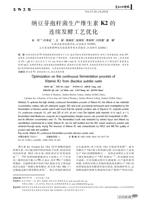
157纳豆芽孢杆菌生产维生素K2的连续发酵工艺优化牟杰1,2,印泽远1,+,王丽1,周凌芸1,张绮悦1,李妙然1,闫冬雷1,姜珊1(1.徐州医学院药学院,江苏徐州221004;2.江苏省新药研究与临床药学重点实验室,江苏徐州221004)收稿日期:2016-04-05+为并列第一作者作者简介:牟杰(1974-),女,博士,副教授,研究方向:药物合成,E-mail :mou.jie@ 。
印泽远(1998-),男,本科生,研究方向:抗肿瘤药物研发,E-mail :2504464354@ 。
基金项目:国家级大学生创新创业训练计划项目(201510313028);江苏省大学生实践创新训练计划重点项目(201510313028Z );江苏省新药研究与临床药学重点实验室主任基金(ZR-XY201403);徐州医学院“振兴计划”。
摘要:为优化维生素K2的高密度连续发酵生产工艺,通过对纳豆芽孢杆菌发酵培养,研究了培养基组成、转速、pH 、溶氧量、后处理技术等因素对维生素K2产量的影响。
实验结果表明以香菇菌渣复配蛋白胨为氮源(5%),甘油为碳源(5%),pH 为7,通气比大于1.5vvm ,转速为600r /min 时,采用高密度连续发酵技术,5L 罐发酵产量最高达35.58mg /L 。
发酵液萃取后,废液再通过纳滤膜截流,提高维生素K2回收率,并制成富含维生素K2的菌菇粉。
维生素K2的结构经高效液相及质谱确证。
大鼠急性毒性实验证明该菌菇粉产品安全无毒。
关键词:维生素K2,连续发酵工艺,纳豆芽孢杆菌Optimization on the continuous fermentation process ofVitamin K 2from Bacillus subtilis nattoMOU Jie 1,2,YIN Ze -yuan 1,+,WANG Li 1,ZHOU Ling -yun 1,ZHANG Qi -yue 1,LI Miao -ran 1,YAN Dong -lei 1,JIANG Shan 1(1.School of Pharmacy ,Xuzhou Medical College ,Xuzhou 221004,China ;2.Jiangsu Key Laboratory of New drug and Clinical Pharmacy ,Xuzhou Medical College ,Xuzhou 221004,China )Abstract :To optimize the high density continuous fermentation process of Vitamin K 2,the effects of raw materials concentration ,rotation rate ,pH ,dissolved oxygen (DO )and post -processing techniques were investigated by the fermentation of Bacillus subtilis natto .It was found that the optimal condition was of Glycerol 5%,soybean protein 2%,mushroom compost 3%,pH 7and DO of 20%at 600r /min .The highest yield reached 35.58mg /L in 5L fermentation tank .Mushroom compost ,as a supplementary nitrogen source ,can promote the biosynthesis of VK 2,and its effective concentration was 3%.The fermentation broth was extracted by extract liquor and filtered by nanofiltration membrane .As a result ,Vitamin K 2can be well isolated and the VK 2mixed mushroom powder was obtained through spray drying .The structure of Vitamin K 2was characterized by HPLC and MS .The quality of product was safe and qualified .Key words :Vitamin K 2;continuous fermentation process ;Bacillus subtilis natto 中图分类号:TS201.3文献标识码:A文章编号:1002-0306(2016)19-0157-05doi :10.13386/j.issn1002-0306.2016.19.022维生素K2(Vitamin K2,VK2)是甲萘醌类脂溶性维生素,可以通过调节体内钙离子沉积,促进骨组织内骨钙素(BGP )的合成,预防和治疗骨质疏松症[1-3]。
纳滤膜的制备方法

纳滤膜的制备方法纳滤膜(Nanofiltration membrane)是一种特殊的滤膜,它具有低压渗透、高选择性、高迁移率、可重复使用等优点,常用于对有机物、离子、小分子等的分离精度更高的过滤,在食品、药物、水处理等领域有广泛的应用。
下面将详细介绍纳滤膜的制备方法。
1、物理法制备纳滤膜:物理法是制备纳滤膜的最常用方法,主要包括液体滤液法、滤凝胶/胶凝/热凝法和蒸发法等。
(1)液体滤液法:液体滤液法是目前使用最广泛的纳滤膜制备方法,主要实现通过滤液系统将溶液中的高分子材料分散形成膜层,然后再经过固化后得到纳滤膜。
在分散出膜层的过程中,可以通过改变溶液的温度、pH值、滤液浓度等条件产生膜层的结构和性能不同。
(2)滤凝胶/胶凝/热凝法:由于液体滤液法所需的条件复杂,而滤凝胶/胶凝/热凝法可以大大简化制备步骤,因此也被广泛应用。
该方法基本原理是在溶液中加入热凝剂,当溶液升温到一定温度时,热凝剂会凝结成膜,之后再经过固化步骤,即可得到纳滤膜。
(3)蒸发法:蒸发法是将溶液浓缩,并将其通过模具的表面进行蒸发形成膜层,然后再经过固化步骤,最后得到纳滤膜。
蒸发法制备纳滤膜的优点是所得膜厚度可控,但缺点是易受外界条件影响,如温湿度等。
2、化学法制备纳滤膜:化学法是制备纳滤膜的常用方法,主要包括聚合物膜法、涂层法、催化聚合物膜法、溶剂热聚合物膜法等,其中溶剂热聚合物膜法是现在应用最广泛的一种方法。
(1)聚合物膜法:聚合物膜法是将原料溶液的聚合物与固定的模具表面进行结合,从而形成膜层,然后再经过固化步骤,最后得到纳滤膜。
(2)涂层法:涂层法是将固定的模具表面涂上膜层,然后再经过固化步骤,最后得到纳滤膜。
(3)催化聚合物膜法:催化聚合物膜法是通过催化剂引发聚合反应,从而形成膜层,然后再经过固化步骤,最后得到纳滤膜。
(4)溶剂热聚合物膜法:溶剂热聚合物膜法是将聚合物溶液加入模具中,然后加热至一定温度,使聚合物发生聚合反应,形成膜层,然后再经过固化步骤,最后得到纳滤膜。
Nanofiltration Membranes
ቤተ መጻሕፍቲ ባይዱ
The water and wastewater treatment segment 分离
Membranes for water and wastewater treatment
membrane-based separation technology
membrane-based separation technology
Membrane Technology for Liquid and Gas Separations
membrane manufacturers and their share of the U.S. market
The combined U.S. market for membranes used in gas and liquid separating applications
waste water treatment, ultrapure drinking water products, water softening and food processing.
ultra filtration超过滤法
Major technologies are ultra filtration (UF), micro filtration (MF),Nano-filtration (NF) and membrane bio-reactors (MBR).
Biological wastewater treatment
Crossflow MBR横流式的MBR
Desalination Pretreatment
Desalination Pretreatment海水淡化预处理
膜法分离一

化工进展Chemical Industry and Engineering Progress2024 年第 43 卷第 3 期膜法分离一/二价阳离子的研究进展赵国珂,张杨,刘轶群(中石化(北京)化工研究院有限公司,北京 100013)摘要:各类工业过程如水质软化、食用盐纯化、盐湖卤水提锂、酸和重金属资源回收等对一/二价阳离子高效分离的需求日益增长,近年来,针对上述分离体系的膜材料的研究取得了诸多进展。
本文详细总结了针对一/二价阳离子分离的选择性阳离子交换膜、纳滤膜、支撑液膜和离子印迹膜的研究进展,重点梳理了相关膜材料的离子选择性优化思路和机理,对比分析了上述膜过程的特点和适用场景。
基于此,作者认为,离子筛分精细化是膜分离技术的重要发展方向。
在分子尺度明晰分离层的形成和演化机理,对于提高界面聚合反应可控度,实现在亚纳米尺度膜结构的精细调控至关重要。
通过在膜基体内可控构建目标离子的特异性识别位点和传质通道,有望实现高选择性离子筛分。
此外,具有本征规则孔道结构的新型分离膜材料,如MOFs 、COFs 、二维层状结构膜等,在精细筛分方面具有良好的发展潜力。
关键词:阳离子交换膜;纳滤膜;液膜;离子印迹膜;一/二价阳离子分离中图分类号:TQ31 文献标志码:A 文章编号:1000-6613(2024)03-1363-11Membrane technologies for monovalent/divalent cation separationZHAO Guoke ,ZHANG Yang ,LIU Yiqun(SINOPEC (Beijing) Research Institute of Chemical Industry Co., Ltd., Beijing 100013, China)Abstract: Efficient separation of monovalent/divalent cations is highly demanded in various industrial processes such as water softening, lithium extraction from salt-lake brine, the production of edible salt and the comprehensive treatment of acidic wastewater. Research on the above membrane materials used in these separation systems has advanced significantly in recent years. This paper presented a comprehensive review of the membrane-based technologies for monovalent/divalent cation separation, including selective cation exchange membranes, nanofiltration membranes, supported liquid membranes and ion imprinting membranes. The optimization strategies and underlying mechanisms for the membrane selectivity were highlighted. The characteristics and applicable scenarios of the above membrane processes were compared. Considering this, it was proposed that the selective ion separation was one of the key areas for membrane separation technology. Clarifying the formation and evolution mechanism of the separation layer at the molecular scale was crucial for improving the controllability of interfacial polymerization reactions. Highly selective ion screening can be realized by controllably constructing recognition sites and mass transfer channels for target ions inside the membrane matrix. Novel membrane materials contained intrinsic and regular pore architectures, such MOFs, COFs, two-dimensional layered membranes, etc ., had good development potential for fine ion selection.DOI :10.16085/j.issn.1000-6613.2023-0463收稿日期:2023-03-24;修改稿日期:2023-04-27。
纳滤膜的发展历程

纳滤膜的发展历程纳滤膜(Nanofiltration membrane)是一种过滤膜技术,其孔径在纳米级别,介于超滤膜和反渗透膜之间。
纳滤膜的发展历程可以追溯到20世纪60年代末。
下面将对纳滤膜的发展历程进行简要介绍。
1967年,美国化学家雷恩金(Reynolds)在一项研究中首次提出了纳滤的概念。
他提出了一种新型膜材料,能够通过纳滤作用实现高通量的离子分离,这为纳滤膜的研究奠定了基础。
1970年代,纳滤膜的研究进展比较缓慢。
科研人员主要关注传统的膜材料如聚醚砜(PES)和聚酯(PET)的纳滤性能改善和优化。
然而,由于限制性较强的孔隙结构和表面电荷效应,纳滤膜的选择性和通量仍然有限。
1980年代至1990年代初,纳滤膜的发展进入了一个新的阶段。
科研人员开始研究和开发新型纳滤膜材料,如聚酰亚胺(PI),聚胺酯(PU)和聚酰胺(PA)。
这些材料具有更高的渗透性和选择性,可以更有效地分离溶质和溶剂。
2000年以后,随着纳米技术的发展,纳滤膜研究进入了一个全新的时代。
科研人员开始探索纳米级孔隙结构和介孔材料在纳滤膜中的应用。
利用纳米材料的特殊性质,如高比表面积和调控孔径大小,纳滤膜的分离性能得到极大的提升。
目前,纳滤膜已经广泛应用于多个领域。
例如,纳滤膜可以用于废水处理,去除溶解性有机物、重金属和离子等;在饮用水处理中,纳滤膜可以去除微生物、有机物和颗粒物。
同时,纳滤膜还可用于食品加工、药物分离纯化、微胶囊制备等。
总之,纳滤膜的发展经历了几十年的探索和进步。
随着材料科学和纳米技术的不断发展,纳滤膜的性能不断改善,应用领域也得到不断拓展。
未来,随着科学技术的不断进步,纳滤膜有望在更多领域发挥作用。
迈博瑞微孔滤膜
About Membrane--What’s Membrane
• Membrane is a selective barrier between two phases, the term "selective" being inherent to a membrane or a membrane process. It should be noted this is a macroscopic definition while separation should be considered at the microscopic level. Membranes can simply be classified by nature into two categories: biological and synthetic membranes. A membrane filter is a thin, polymeric film or filament made up of millions of microscopic pores. Membranes have many different properties that affect the performance of the filter in applications. membrane filters are classified according to their structures into several categories in terms of "pore size" (listed from smallest to the largest); namely, gas separation, nanofiltration, reverse osmosis, ultrafiltration, and microporous membranes
NOVEL INORGANIC NANOFILTRATION MEMBRANES
专利名称:NOVEL INORGANIC NANOFILTRATION MEMBRANES发明人:GRANGEON, ANDRE申请号:EP02783208.8申请日:20020925公开号:EP1436072A1公开日:20040714专利内容由知识产权出版社提供摘要:An inorganic nanofiltration membrane comprises a macroporous titanium oxide support, one or more intermediate separating layers and a top separating layer for nanofiltration in metal oxide Preferred Features: The cut threshold is 100-2000 daltons, preferably 800-2000 daltons. The membrane is tubular or planar. The nanofiltration layer has a specific mass of 2-4 g/m<2>, preferably 3 g/m<2> and is made of titanium oxide. The intermediate separating layer is made of a metal oxide, preferably titanium oxide. The intermediate separating layer contains an ultrafiltration layer in metal oxide (preferably titanium oxide or zirconium oxide) deposited on a microfiltration layer in metal oxide (preferably titanium oxide), deposited on the support. The nanofiltration layer is obtained by forming a base by polycondensation of a corresponding metal alcoxide in alcohol in the presence of a gelling agent; deposit of this base on the support or the intermediate separating layer; drying the base to form a gel and fritting the gel thus obtained. Alternatively, the nanofiltration layer is obtained by forming a base by hydrolysis of a corresponding metal alcoxide followed by peptization; deposit of this base on the support or the intermediate separating layer; drying the base to form a gel and fritting the gel thus obtained.申请人:TECHNOLOGIES AVANCEES & MEMBRANES INDUSTRIELLES,GRANGEON, ANDRE地址:Z.A. Les Laurons 26110 Nyons FR,14, avenue Anatole France 84600 Valreas FR 国籍:FR,FR代理机构:Sarlin, Laure V.更多信息请下载全文后查看。
纳米过滤网过滤和污水的作文四百字
纳米过滤网过滤和污水的作文四百字英文回答:Filtering wastewater using nanofiltration membranes is an effective and efficient method for water treatment. Nanofiltration membranes are designed with tiny pores that can selectively remove contaminants from the water, such as bacteria, viruses, and organic compounds. The filtration process involves the use of pressure to force the wastewater through the membrane, allowing only clean water to pass through while retaining the pollutants.One of the advantages of using nanofiltration membranes for wastewater treatment is their high removal efficiency. These membranes can effectively remove a wide range of pollutants, including heavy metals, pesticides, and pharmaceuticals. This ensures that the treated water meets the required quality standards for reuse or discharge into the environment.Another benefit of nanofiltration membranes is their ability to operate at low pressure. Compared to other filtration methods, such as reverse osmosis, nanofiltration requires less energy to push the water through the membrane. This not only reduces operational costs but also makes the process more sustainable.Furthermore, nanofiltration membranes are highlydurable and resistant to fouling. Fouling refers to the accumulation of particles and organic matter on the surface of the membrane, which can decrease its efficiency over time. However, nanofiltration membranes are designed to resist fouling, resulting in longer membrane lifespan and less frequent maintenance.In addition to these advantages, nanofiltration membranes offer a compact and modular design, making them suitable for both large-scale and small-scale applications. They can be easily integrated into existing water treatment systems or used as standalone units for decentralized wastewater treatment.Overall, nanofiltration membranes provide an efficient and reliable solution for filtering wastewater. Their high removal efficiency, low operating pressure, durability, and versatility make them an ideal choice for various water treatment applications.中文回答:使用纳米过滤网过滤污水是一种有效和高效的水处理方法。
纳滤膜的工作原理及特点
纳滤膜的工作原理及特点纳滤膜(Nanofiltration membrane)是一种新型的分离膜,具有较高的分离性能和选择性,广泛应用于水处理、食品加工、制药、化工等领域。
本文将详细介绍纳滤膜的工作原理及其特点。
一、工作原理纳滤膜的工作原理基于纳米级孔隙的存在。
纳滤膜由多层薄膜组成,包括支撑层和活性层。
支撑层通常由聚酰胺、聚酯等材料制成,具有较高的机械强度和疏水性,可提供支撑和稳定性。
而活性层则是关键部分,通过控制孔隙大小和形状,实现对溶质的选择性分离。
当溶液通过纳滤膜时,溶质分子会受到膜表面的孔隙和电荷的影响。
较小的溶质分子可以通过纳滤膜的孔隙,而较大的溶质分子则被滞留在膜表面,从而实现了分离。
此外,纳滤膜还具有一定的电荷选择性,可以通过电荷交互作用进一步筛选溶质。
二、特点1. 分离性能优异:纳滤膜的孔隙尺寸通常在纳米级别,能够有效分离溶液中的微小颗粒、胶体、有机物等。
相较于超滤膜,纳滤膜的分离效果更加显著。
2. 选择性较高:纳滤膜能够根据溶质的分子大小和电荷选择性地分离,对不同溶质具有较好的筛选效果。
这使得纳滤膜在水处理、废水回收和浓缩等领域有着广泛的应用。
3. 通量较大:纳滤膜的通量通常比反渗透膜高,能够在较短的时间内处理大量溶液。
这对于大规模工业生产具有重要意义。
4. 操作条件较温和:相较于反渗透膜,纳滤膜的操作条件较为温和,能够更好地保护溶质的活性物质。
这对于食品加工和制药行业来说尤为重要。
5. 能耗较低:纳滤膜相对于其他膜分离技术来说,能耗较低。
这不仅可以降低生产成本,还有利于环境保护。
6. 易于清洗和维护:纳滤膜的结构相对简单,容易清洗和维护。
这可以延长膜的使用寿命,减少更换成本。
7. 应用广泛:纳滤膜在水处理、食品加工、制药、化工等领域有着广泛的应用。
例如,可以用于海水淡化、废水处理、果汁浓缩等。
总结:纳滤膜是一种具有优异分离性能和选择性的膜分离技术。
其工作原理基于纳米级孔隙的存在,通过控制孔隙大小和形状,实现对溶质的选择性分离。
耐碱纳滤膜设备工艺原理

耐碱纳滤膜设备工艺原理引言耐碱纳滤膜设备是当今水处理领域应用最广泛的膜技术之一。
它是利用超薄环境逆渗透膜和分离膜的物理作用对水进行处理,以获得高质量的水。
本文将介绍耐碱纳滤膜设备的工艺原理。
膜技术概述纳滤膜(Nanofiltration Membrane,NF)是介于超滤膜和反渗透膜之间的一种新型压力驱动分离膜,其截留分子量范围为200~1000道尔顿,可以有效地去除有机物、无机盐和某些重金属离子等物质。
NF 技术被广泛应用于饮用水工业、生活污水处理、给水处理、化工及制药等领域。
耐碱纳滤膜设备原理耐碱纳滤膜设备采用过滤和截留的原理,将水中的有害物质分离出来,得到纯净水。
主要原理包括:碱度调节膜的性能和使用寿命与水的碱度密切相关。
如果水中碱度过高,则会损害膜的结构和性能。
而碱度过低则会导致水质受到污染。
因此,在膜处理过程中需要进行碱度调节,以确保膜的正常运行。
预处理膜前预处理是保证纳滤膜正常运行、延长使用寿命的关键。
它可以有效地去除水中的悬浮物、泥沙、藻类、残留氯等物质,减少膜的污染,增加水的通透性。
膜分离耐碱纳滤膜设备采用纳滤膜进行过滤和截留,将水中的有害物质隔离出来,保留对人体有益的矿物质和微量元素。
膜的数量和规格取决于所需水质的纯净程度和流量大小。
冲洗冲洗是防止膜的堵塞和保证膜的通透性的重要环节。
冲洗之前需要保证通入的清洗液的温度和性质与处理水的相同,然后用高压清洗机进行清洗。
循环系统循环系统是纳滤膜设备中的重要部分,它包括控制器、泵、管道、压力表等。
通过循环系统可以掌控整个膜分离过程,保证各环节按照设计要求顺利进行。
结论通过本文的阐述,我们可以看出,耐碱纳滤膜设备是一种高效、环保、经济的水处理技术。
在实际应用中,需要进行碱度调节、预处理、膜分离、冲洗以及循环系统的控制和管理等一系列环节,以确保纳滤膜设备正常运转,并得到高质量的水资源。
相信,随着人们对水资源的重视和对环保科技的不断研究,耐碱纳滤膜设备的应用前景也将越来越广阔。
正电荷纳滤膜
正电荷纳滤膜
正电荷纳滤膜(Positive charged nanofiltration membrane)是一
种具有正电荷表面的纳滤膜。
纳滤膜是一种具有较小孔隙大小的膜,可以用来分离溶液中的溶质和溶剂。
正电荷纳滤膜通常由聚合物材料制成,并在其表面引入正电荷官能团。
正电荷纳滤膜的正电荷表面可以吸附带有负电荷的溶质,如阴离子、有机酸、重金属离子等,和中性或正电荷的溶质相比更容易通过膜孔。
这样,正电荷纳滤膜可以实现对带负电荷的溶质的选择性分离和去除。
例如,在水处理领域,正电荷纳滤膜可以用来去除水中的重金属离子和高分子有机物,以提高水质。
正电荷纳滤膜还具有良好的抗污染性能,可以减少膜的污染和阻塞。
这是因为正电荷表面可以吸引和排斥不同类型的溶质,防止它们在膜表面沉积和堆积。
总的来说,正电荷纳滤膜在分离和过滤应用中具有广泛的应用潜力,可以用于水处理、生物医药、食品和饮料等领域。
纳米过滤网作文700字
纳米过滤网作文700字英文回答:Nanofiltration membranes are a type of filtration technology that utilizes nanoscale pores to separate particles and molecules based on their size and charge. These membranes are commonly used in various industries, including water treatment, food and beverage, pharmaceuticals, and chemical processing. They are highly efficient in removing contaminants, such as bacteria, viruses, heavy metals, and organic compounds, from liquids.One of the advantages of nanofiltration membranes is their ability to selectively remove specific ions while allowing others to pass through. This is due to the sizeand charge characteristics of the ions. For example, in water treatment applications, nanofiltration membranes can effectively remove divalent ions like calcium and magnesium, which are responsible for water hardness, while allowing monovalent ions like sodium and chloride to pass through.This selective removal helps improve the taste and qualityof the treated water.Another advantage of nanofiltration membranes is their high permeate flux. Permeate flux refers to the rate at which the liquid passes through the membrane.Nanofiltration membranes have a relatively high permeateflux compared to other types of membranes, such as reverse osmosis membranes. This means that they can process alarger volume of liquid in a shorter amount of time, making them more efficient and cost-effective.Furthermore, nanofiltration membranes are capable of operating at lower pressures compared to reverse osmosis membranes. This reduces the energy consumption andoperating costs associated with the filtration process. Lower operating pressures also result in less fouling and scaling on the membrane surface, prolonging its lifespanand reducing the need for frequent cleaning and maintenance.In addition to their advantages, nanofiltration membranes also have some limitations. One limitation istheir susceptibility to fouling. Fouling occurs when particles or substances in the feed solution accumulate on the membrane surface, reducing its performance and efficiency. However, this can be mitigated through regular cleaning and maintenance procedures.Another limitation is the relatively high cost of nanofiltration membranes compared to other filtration technologies. The production and fabrication of nanofiltration membranes involve advanced materials and manufacturing processes, which contribute to their higher cost. However, the benefits and advantages they offer often outweigh the initial investment, especially in applications where high-quality filtration is required.中文回答:纳米过滤网是一种利用纳米级孔隙根据颗粒和分子的大小和电荷进行分离的过滤技术。
- 1、下载文档前请自行甄别文档内容的完整性,平台不提供额外的编辑、内容补充、找答案等附加服务。
- 2、"仅部分预览"的文档,不可在线预览部分如存在完整性等问题,可反馈申请退款(可完整预览的文档不适用该条件!)。
- 3、如文档侵犯您的权益,请联系客服反馈,我们会尽快为您处理(人工客服工作时间:9:00-18:30)。
Journal of Membrane Science269(2006)84–93A novel nanofiltration membrane prepared with PAMAMand TMC by in situ interfacial polymerization onPEK-C ultrafiltration membraneLi Lianchao a,∗,Wang Baoguo a,Tan Huimin b,Chen Tianlu c,Xu Jiping da Department of Chemical Engineering,Tsinghua University,Beijing100084,Chinab School of Chemical Engineering and Material,Beijing Institute of Technology,Beijing100081,Chinac Institute of Applied Chemistry,Chinese Academy of Sciences,Changchun133022,Chinad School of Chemistry and Chemical Technology,Shanghai Jiaotong University,Shanghai200030,ChinaReceived9October2004;received in revised form31May2005;accepted9June2005Available online19July2005AbstractA novel nanofiltration membrane(PEK-C NF membrane)prepared with poly(amidoamine)(PAMAM)dendrimer and trimesoyl chloride (TMC)by in situ interfacial polymerization on phenolphthalein poly(ether ether ketone)(PEK-C)ultrafiltration membrane was investigated. FTIR–ATR,XPS,SEM and contact angle of the water were employed to characterize the chemical and physical changes of resulting membranes.Theflux and rejection of resulting membranes increased with increasing concentrations of PAMAM and/or generation numbers of PAMAM for NaCl concentration.Both rejection andflux decrease with an increase of MgSO4concentration.The salts rejections order of resulting membrane is MgCl2>MgSO4>NaCl>Na2SO4,which shows that resulting membranes were all positively charged NF membrane. Influences of operating temperature onflux and rejection of different solutes show that resulting membrane is thermostable at higher temperature (e.g.80◦C).The PEK-C NF membrane is especially suitable for separating cationic solutes from others by increasing operating temperature. The pH in the feed increase from2to9resulted in over two-fold increase in theflux for NaCl solution.Therefore the PEK-C NF membrane is also particularly suitable for treating acidic feed.The studied membrane possesses maximum operating pressure lower than2.0MPa and excellent stability during1080h(1.5months)of continuousfiltration at30◦C.©2005Elsevier B.V.All rights reserved.Keywords:PAMAM;PEK-C;Nanofiltration membrane;Interfacial polymerization1.IntroductionNanofiltration(NF)is increasingly gaining attention in many separation and treatment processes such as water softening,color removal,chemical oxygen demand(COD) reduction and separation of medicines[1–3].NF membranes are often negatively charged,displaying separation charac-teristics in the intermediate range between reverse osmosis (RO)and ultrafiltration(UF).NF membranes generally have a thin skin layer enabling higherfluxes and lower operating pressures than RO membranes and are able to ∗Corresponding author.Tel.:+861062795275.E-mail address:lc-li@(L.Lianchao).reject small organic molecules having molecular weights as low as200–500Da such as many medicines(streptomycin, penicillin etc.).Moreover,NF membranes are also able to reject ions,especially bivalent ions,due to the Donnan effect [4]stemming from the membrane charge[5,6].There are many methods for the preparation of com-posite membranes for NF including vapor deposition[7], plasma-initiated polymerization[8–11],photo-initiated polymerization[12],the radiation polymerization[13], the dip coating process[14],interfacial polymerization [15,16],electron beam irradiation[17],atom transfer radical polymerization[18],resin-filled chelating[19],and in situ amines cross-linking[20].Interfacial polymerization, however,is still a key method to produce commercial NF0376-7388/$–see front matter©2005Elsevier B.V.All rights reserved. doi:10.1016/j.memsci.2005.06.021L.Lianchao et al./Journal of Membrane Science269(2006)84–9385Fig.1.Structure of PAMAM G1.0dendrimer. membranes such as the NF series(Filmtec Corporation),the NTR series(Nitto Denko Company),the UTC series(Toray Industries)and so forth.Although they have been used in manyfields successfully,it should be an important promising work for membrane manufacturing to develop a novel NF membrane with special properties using high performance materials.Dendrimers developed as novel high performance materi-als over the past decade have received a great deal of atten-tion because they have numerous terminal functional groups and a highly branched structure.The most-studied den-drimer is probably the so-called polyamidoamine(PAMAM) dendrimer,which has a global shape containing much higher amino group densities on the surface than conven-tional macromolecules,as is schematically shown in Fig.1. These dendrimers are typically synthesized by the repeti-tive Micheal addition and aminolysis[21].The high density of their terminal groups provides a large number of reac-tive sites[22]for potential application as nanoscale cata-lysts,micelle mimics,drug delivery agents,chemical sensors,high-performance polymers,and adhesives[23,24].In recent years,some studies have appeared in the literature describ-ing the applications of PAMAM in the membrane separation field,including PAMAM supported UF to improve separation performance of UF[25],PAMAM dendrimer-induced cross-linking modification of polyimide membranes to enhance CO2permeability[26],using PAMAM as liquid membrane to improve separation performance of CO2from gas mix-tures[27–29],and grafting PAMAM and poly(acrylic acid) onto Au-coated Si wafer to prepare pH-switchable modified-electrode for probing both cationic and anionic redox-active molecules[30].Up to now,few researchers prepared NF membranes with dendrimers,Willem and co-workers pre-sented their primary study on NF membrane formation with poly(propyl imine)(PPI)dendrimers polymerized with TMC [31].However,Preparation of PPI dendrimer suffered from the shortcoming of material cost,higher pressure operation and low yield.On the contrast,PAMAM can be synthesized under normal pressure at room temperature,and possesses the similarity to PPI in its chemical structure and physical ing PAMAM to develop a novel NF membrane with special properties is expected to be a promising method in the future(Fig.2).Poly(ether ether ketone)containing the cardo group of phenolphthalein(PEK-C)developed by ours,has super ther-mal stability(T g up to228◦C),chemical resistance(only resolved in DMF or DMAC or DMSO)and excellent mem-brane formation property,the PEK-C membrane has showed good selectivity and permeationflux for both gases and liq-uids[32–35].PEK-C was expected to play important parts in the development of NF membrane.The objective of this study focuses on developing novel NF membrane from PAMAM and TMC by in situ interfacial polymerization process,using PEK-C as substrate membrane,and investigating its desali-nation properties.Several surface analytical techniques were used to characterize the chemical and physical changesin Fig.2.Scheme of PEK-C synthesis.86L.Lianchao et al./Journal of Membrane Science269(2006)84–93 the resulting membranes.Additionally,resulting PEK-C NFmembranes performance were characterized by measuringsome soluteflux and/or rejection.Influences of operatingpressure and temperature and pH on soluteflux and/or rejec-tion were also investigated.2.Experimental2.1.Synthesis of PAMAM and PEK-C materials2.1.1.Synthesis of PAMAMPoly(amidoamine)dendrimers were synthesized bymeans of the procedure described by Tomalia et al.[22]whereethylenediamine was used as a nitrogen core,and a repeatedstepwise reaction was conducted including Michael additionand aminolysis.Repetition of these sequences was used tomake successively higher generations.The structure of thePAMAM G1.0dendrimer is shown in Fig.1.The reactionprocess was as follows:NH2CH2CH2NH2+4CH2CHCOOCH3Micheal addition−→Step1Aminolysis−→Step2PAMAM G0Step1−→Step2PAMAM G1Step1−→Step2PAMAM G2where all reagent was purchased from Beijing Fine Chemi-cal Industry Co.and purified before use,PAMAM was further purified before use according to the method described else-where[38].2.1.2.Synthesis of PEK-C materialsPhenolphthalein poly(ether ether ketone)(PEK-C)with high molecular weight were synthesized via solution nucle-ophilic polycondensation reaction of phenolphthalein and 4,4 -difluorobenzophenone in the presence of potassium car-bonate.The process of synthesis was shown in Fig.2.In a 500mL three-necked round bottomflask,10.61g(50mmol) of4,4-difluorobenzophenone,15.91g(50mmol)of phe-nolphthalein and7.59g of potassium carbonate were dis-solved in a mixture of100mL dimethyl sulfoxide(DMSO) and50mL toluene.The mixture was refluxed for5h under a constant stream of nitrogen.After the water was essentially removed from the reaction mixture by azeotropic distillation, the temperature was raised to175◦C to distill out the toluene. The solution was kept at this temperature for6h,and then the reaction mixture was poured into a great deal of ethanol to precipitate the polymer.White Solid PEK-C was obtained, Mn=12,653,yield91%.DMSO,phenolphthalein and potassium carbonate pur-chased from Beijing Chemical Reagent Company were purified or dried before use;4,4 -difluorobenzophenone was purchased from Aldrich and other reagents and solvents were obtained commercially and used without further purification.2.2.Preparation of microporous PEK-C UF support membranePEK-C casting solution was prepared by dissolving 15wt.%PEK-C in N,N-dimethylformamide(DMF)at 50–70◦C with continuous stirring.The resultant polymer solution was cast on a glass plate and gelled in a water bath consisting of2%ethanol.After10min of gelation,the resulting PEK-C membrane was removed from the gela-tion bath and washed thoroughly with deionized water to remove all DMF.The membrane was then subsequently employed as a support medium for the NF membrane.Molec-ular weight cut-off of the resulting UF membrane is50,000. The entire casting operation process was kept at a tempera-ture of25–30◦C with a relative humidity of30–35%.The PEK-C/PEG/DMF solution consisted of15wt.%PEK-C, 15wt.%PEG(M W=300)as pore-former and70wt.%DMF. In all experiments,deionized water(produced by RO)was used.N,N-dimethylformamide(DMF)(A.R.grade),PEG (M W=300)and ethanol were obtained commercially and used without further purification.2.3.Fabrication of the PEK-C NF membranesThe PEK-C NF membrane was fabricated to form an active skin layer containing PAMAM units over the microporous PEK-C UF membrane by adopting the in situ interfacial polymerization technique.A typical PEK-C NF membrane was prepared by allowing the plate sheet PEK-C UF substrate membranes to be submerged in a 11.2×10⁻⁵mol/L aqueous solution of PAMAM G0,to which0.01wt.%of sodium dodecylsulfate(SDS)had been added as a surfactant.The excess solution was allowed to drip off the substrate membranes.They were then immersed for60s at room temperature in a10.5×10−5mol/L solution of TMC in hexane.This resulted in the formation of a thin polyamidefilm on the microporous surface of the PEK-C UF membrane.The composite membranes obtained then underwent heat treatment in an oven for10min at80◦C to attain the desired stability of the formed structure.PAMAM were synthesized by ourselves,and was purified by the other nanofiltration membrane before use[36];TMC was purchased from Aldrich and other reagents and solvents were obtained commercially and used without further purifi-cation.2.4.Membrane performance evaluationThe PEK-C NF membranes were evaluated for permeate flux and rejection on a cross-flow NF test cell with an active membrane area of24cm2.Testing was done with NaCl salts solution of1000mg L−1at a pressure of0.6MPa.Circular membrane samples were placed in the test cell with the active skin layer facing the incoming feed.The membrane sample was supported on a porous stainless steel sintered disc with a rubber O-ring around it.The membrane feed solution sideL.Lianchao et al./Journal of Membrane Science 269(2006)84–9387was stirred.Before testing F and R ,deionized water from a reservoir was pressurized through the membranes for at least 20min at 0.8MPa in order to stabilize membranes.Then the flux was repeatedly measured by collection of the filtrate for given periods until a stable value of the permeation flux was observed.Values of three membranes were averaged.The filtration characteristics including permeation flux (F )and rejection (R )were determined under a pressure difference of 0.6MPa at ambient temperature.The permeation flux was calculated as Eq.(1):F =V At(1)where V is the total volume of the solution permeated dur-ing the experiment,A the effective membrane area,and t the operation time.The rejection,R ,was calculated using Eq.(2):R =1−C p C f(2)where C p and C f are the concentration of the permeate and the feed,respectively.Salt concentrations in the feed and permeate were determined by Electrical Conductiv-ity DDS-11A (Shanghai Leichi Instrument,China).Sac-charose (M W =342)and safranine T (M W =351)concen-trations in the feed and permeate were measured using a UV Spectrophotometer-751(Shanghai Angles Instrument,China).Sodium chloride,sodium sulfate,magnesium chloride,magnesium sulfate,safranine T and saccharose were obtained commercially as reagent grade chemicals and used as received.2.5.Analytical technique for characterization of active layerFTIR-ATR spectroscopy (FTIR-ATR)spectra were recorded using a Nicolet IR 560spectrometer with a hor-izontal ATR accessory equipped with a ZnSe crystal.For evaluation,32scans were taken at a resolution of 4cm −1.X-ray photoelectron spectroscopy (XPS)analysis was performed using a Perkin-Elmer Phi-5300X-ray photoelec-tron spectrometer with a monochromatized Al K ␣(15kV ,250mA)X-ray source.Vacuum during analyses was con-ducted at 10.10–10.9Pa.The take off angle between the analyzer and the sample surface was 45.For calibration the carbon C 1s peak was used (285eV).A JEOL JSM 6301F scanning electron microscope (SEM)operated at 20kV was used to analyze the porous membrane for the PEK-C NF membrane.Contact angles of membranes were determined on a level surface with water for 1min in air at 25◦C using a JY-82Contact Angle Analyzer (Chengde Experimental Equipment,China).Fig.3.FTIR-ATR of PEK-C NF membrane (a)and PEK-C UF membrane (b).3.Results and discussion 3.1.FITR-ATR studyIn order to obtain information about the structural changes of PEK-C NF membrane resulting from in situ interfacial polymerization of PAMAM and TMC,FTIR spectra of the surface region of PEK-C UF and PEK-C NF membranes were recorded using the ATR technique,as shown in pared with the PEK-C UF membrane,the IR spectra of the NF membranes exhibited evident absorbance signals at 2846,2920(C H)and around 3292cm −1(νN H).The similar spectra for the PEK-C UF membrane were not observed.Though the PEK-C UF membrane had a signal at 1648cm −1assigned to aryl carbonyl in PEK-C,the PEK-C NF membrane had a stronger signal at 1648cm −1assigned to carbonyl in the amido bond.This suggested that the active skin layer of the PEK-C NF membrane was polyamide containing amido bonds and amino and alkyl groups after in situ interfacial polymerization of PAMAM and TMC.3.2.XPS analysisThe chemical changes that occurred in the PEK-C NF membranes as a result of in situ interfacial polymerization of PAMAM with TMC were further ascertained by XPS anal-ysis.The XPS survey scans for the investigated samples are shown in pared with virgin PEK-C UF membrane,a nitrogen-containing functionality peak was observed,and the oxygen-containing functional peak was also higher than the PEK-C UF membrane.That can be attributed to active skin layer of the PEK-C NF membrane containing amino groups and amide bonds after interfacial polymerization of PAMAM with TMC.88L.Lianchao et al./Journal of Membrane Science269(2006)84–93Fig.4.XPS survey scans of PEK-C UF membrane(a)and PEK-C NF mem-branes(b).3.3.SEM imageThe active skin layer and cross-section morphology of the PEK-C NF membrane are shown in SEM patterns (Fig.5).In Fig.5,photo(a)was cross-section in NF PEK-C membrane,photo(b)was the active skin layer of the NF PEK-C membrane which located to the bottom in photo (a).And photo(b)was enlarged region which located to active skin layer in photo(a),photo(c)was also enlarged region which located to the top in photo(a),photo(d)was enlarged region which located to top in photo(c).The active skin layer in NF PEK-C membrane(Fig.5a and b)was an uniform,smooth and dense layer,no pore structure could be found on the active layer,so there was no porefilling found in the UF membranes.In fact,the pore sizes on the active skin layer of the NF membranes were usually in the magnitude of nanometers.It is often difficult to observe the pore structure of NF membrane surfaces using SEM.On the other hand, the cross-section photos(Fig.5a,c and d)showed that the PEK-C UF membrane was a good microporous membrane because it had regularfinger-like pores and sponge-like pores in the walls of pores(Fig.5c and d)enabling goodflux.3.4.Effects of concentrations of PAMAM and TMC on F and R of the PEK-C NF membranePerformance of the PEK-C NF membranes prepared under various concentrations and generation numbers of PAMAM are shown in Table1.Flux and rejection of the PEK-C NF membrane increased with increasing concentrations of PAMAM or generation numbers of PAMAM,except the R of NF1.This was ascribed to the fact that amino groups in the active skin layer increased with increasing concentrations of PAMAM and/or generation numbers of PAMAM;further-more these amino groups could improve thehydrophilicity Fig.5.SEM of PEK-C NF membrane(a)survey(b)active layer(c)microporous substrate(d)microporous wall in substrate.L.Lianchao et al./Journal of Membrane Science269(2006)84–9389 Table1Effects of concentration of PAMAM and TMC on F and R of the PEK-C NF membraneMembrane Generation numbers of PAMAM Concentration of reagents NF membrane propertiesPAMAM(×10−5mol/L)TMC(×10−5mol/L)F(L m−2h−1)R(%)NF1G0(4)a 4.7(18.8)b10.5(31.5)c39.243.7NF2G0(4)11.2(44.8)10.5(31.5)37.536.2NF3G0(4)16.8(67.2)10.5(31.5)51.257.8NF4G0(4)31.7(126.8)10.5(31.5)49.758.2NF5G1(8) 6.6(52.8)10.5(31.5)45.648.1NF6G1(8)10.9(87.2)10.5(31.5)51.852.4NF7G1(8)15.2(121.6)10.5(31.5)61.269.5NF8G1(8)32.1(256.8)10.5(31.5)59.568.8NF9G2(16)15.9(254.4)10.5(31.5)68.272.5 Operating pressure:0.6MPa;NaCl concentration:1000mg L−1.a Denotes number of amino group per molecule.b Denotes total number of amino group.c Denotes total number of acryl chloride group.of the PEK-C NF membrane so as to attain a higherflux. On the other hand,these amino groups and/or tertiary amino groups in water were able to be changed into RH3N+and R3HN+because of the combination of the lone electron pair on N and water[37].As the concentration of amino groups on membrane surface increase,RH3N+and R3HN+on the membrane surface increase,the repulsion between mem-brane with ions in feed is intensified,result in rejection of salts for this membrane increase.However,as concentration of PAMAM is more than three-fold of TMC concentration, effect of PAMAM concentration onflux and rejection is not obvious.Flux and rejection of NF3are similar to NF4,or NF7to NF8,as shown in Table1.Table1shows that the R of NF1was higher than NF2.This was mainly because TMC act as cross-linking point during interfacial polymerization,and the more cross-linking points, the more dense the cross-linked structure of the active layer. Therefore,the R of NF membrane decreased with decreasing PAMAM concentration.Different separation performances of the NF membranes could be obtained by changing the concentrations and generation numbers of PAMAM and/or TMC.3.5.Effects of different membranes on contact angle of waterThe contact angles of the PEK-C UF membranes and the PEK-C NF membranes using interfacial polymerization of PAMAM and TMC are listed in Table2.The contact angles of the NF membranes were lower than those of the PEK-C Table2The contact angles of NF membrane and UF membrane for water Membrane Contact angleθ(◦)UF membrane51NF142NF337NF633NF930UF membrane.This indicates an increase in membrane sur-face hydrophilicity due to the introduction of NH2groups to the membrane active layer,and hydrophilicity increased with increasing PAMAM concentration and/or the number of PAMAM generations.3.6.Rejection of different salts for PEK-C NF membranesThe rejection for different salts and their solutionflux was compared for NF2and NF5and NF9as shown in Table3.The salts rejections order of these three mem-branes is MgCl2>MgSO4>NaCl>Na2SO4.which is simi-lar to the sequence developed by Runhong Du[38],whereas this order is opposite to the one developed by Yu[39,40], i.e.Na2SO4>NaCl>MgSO4>MgCl2,where the negatively charged NF membranes was used.This sequence shows that PEK-C NF membranes used were all positively charged nanofiltration membrane.This order can be explained by Donnan exclusion[41,42].A positively charged nanofil-tration membranes have higher rejections for high-valence cations and low-valence anions than low-valence cations and high-valence anions.These results demonstrate that the rejec-tion to salts for a NF membrane is not only related with the pore size of the membrane,but also largely depends on the electrostatic action between the membrane and ions in solu-tion.Therefore,the separation property to salts of positively charged NF membranes will be very different from negatively charged NF membranes.The rejection of NaCl for NF9is Table3Performances of NF PEK-C membranes for different salts solutionSalts NF2(G0),R(%)NF5(G1),R(%)NF9(G2),R(%) MgCl277.284.295.7MgSO467.672.385.1NaCl36.248.172.5Na2SO438.247.658.2Driven pressure:0.6MPa;concentration of Na2SO4,MgSO4and NaCl and MgCl2:1000mg L−1,respectively.90L.Lianchao et al./Journal of Membrane Science269(2006)84–93Fig.6.The effect of MgSO4concentration on rejection andflux. 72.5%and the rejection of MgSO4is85.1%,showing that the NF9membrane is an excellent NF membrane.3.7.Effect of MgSO4concentration on R and F for NF7 membraneThe effect of MgSO4concentration on rejection and solu-tionflux for NF7under operating pressure of0.6MPa is shown in Fig.6.MgSO4concentration effects greatly on its rejection andflux.Both rejection andflux decrease with an increase of MgSO4concentration.The sequence can be explained by Donnan exclusion[41].As the ionic concen-tration increases,the electrostatic repulsion effect of the electrolytic membrane on the ions decreases,resulting in a decrease in rejection.Otherwise,the osmotic pressure increases with increasing the ionic concentration,the actual driving force of the system( P− π)is also reduced,result-ing in a decrease in waterflux.3.8.Effect of operation pressure on R and F of NF6 membraneEffect of operating pressure on the permeateflux and rejection of MgSO4(1000mg L−1)was investigated using NF6membrane.As can be seen in Fig.7,the permeateflux increases linearly with the operation pressure,and the change ratio is77.3L m−2h−1MPa−1.The permeateflux is in direct proportion to the operation transmembrane pressure which is the difference of operating pressure and osmoticpressure.Fig.7.Effect of operating pressure on R and F. Compared with the operating pressure,the osmotic pressure is so low that it can be neglected for the low concentration of salts.Therefore,the operating pressure is approximate to the transmembrane pressure.Other explanations based on equa-tion was appeared in previous literatures[42,43].Fig.7also shows that with operating pressure increasing in a certain range,the salt rejection of NF membrane is improved.This sequence is explained by Eq.(3):F=B C S(3)where B is the salt permeation coefficient, C S is salt the concentration difference on the two sides of the membrane, respectively.As P increases,waterflux increases, C S increase too,these effects combine to result in a gradual increase in salt rejection.These influencing trends are similar to sequences in previous reports[44,45].3.9.Effect of operating temperature on R and F of different solute using NF7membraneThe influence of operating temperature on rejections and solutionfluxes of MgSO4,sucrose and safranine T was determined using NF7membrane.Table4shows a trends of rejection for MgSO4decreased from82.4to72.6%, but the solutionfluxes increased two-fold with increase of the operation temperature.NF7membrane maintained 95.8–92.9%rejection of safranine T even though the solution flux increased nearly2.5-fold.In addition,molecular weight of safranine T is similar to sucrose,but the rejections ofTable4Effect of operating temperature on R and F of different solutes for NF7Temperature(◦C)MgSO4(M W=120)Sucrose(M W=342)Safranine T(M W=351)F(L m−2h−1)R(%)F(L m−2h−1)R(%)F(L m−2h−1)R(%) 2557.482.433.890.127.895.8 5078.678.558.684.546.594.1 80118.572.673.577.969.392.9Driven pressure:0.6MPa,Na2SO4concentration:1000mg L−1and safranine T and sucrose concentration:1000mg L−1,respectively.L.Lianchao et al./Journal of Membrane Science269(2006)84–9391Fig.8.Effect of pH in feed on F and R for NF3. safranine T dye were distinctly higher than sucrose.This ascribes to that electrostatic repulsion between the positively charged NF7membrane and cationic safranine T.When the temperature was returned back to25◦C,results similar to the original values were obtained.When the tem-perature was increased again,similar values were obtained again.This shows that the PEK-C NF membrane is ther-mostable at or below80◦C and gives reproducibleflux and rejection characteristics when changed temperatures repeat-edly.Table4shows that NF7membrane is especially suitable for separating cationic solutes from others by increasing oper-ating temperature.3.10.Effect of pH in feed on the PEK-C NF membraneflux of NaCl solutionFig.8shows the effect of pH in the feed on solutionflux for the NF3membrane(pH in the solution was adjusted from 2to9using sodium hydroxide and hydrochloric acid.The pressure applied wasfixed at0.6MPa.The feed solution is 1000mg L−1NaCl solution).Interestingly,it was found that the PEK-C NF membranes,when the pH is lowered(pH2,3 and5),exhibit higherfluxes,compared with theflux at pH7 or9using the same membranes,especially,theflux(at pH2) is higher than two-fold of theflux(at pH7).This implies that amino groups(NH2)groups and/or tertiary amino groups on the membrane surface interact with ions in the feed.As the pH in feed is decreased,amino groups on membrane surface changed into RH3N+,R3HN+[37].The electrostatic repul-sion between charged membrane and H+in the feed decreased due to more NH2groups on the surface of the membrane transferring to NH3+,resulting in enlarged pore surface. In contrast,increasing the pH in the feed,NH2groups on the surface of the membrane were not able to transfer into NH3+,and the electrostatic repulsion between membrane and ions increases,resulting in the shrinkage of pores on the membrane surface.This results are similar to NF mem-brane made from PPI dendrimer and TMC[31].Therefore the PEK-C NF membrane prepared with PAMAM and TMCby Fig.9.Effect of operating pressure onflux of NF1membrane at30◦C,when a solution containing1000mg L−1NaCl.interfacial polymerization is particularly suitable for treating acidic feeds.3.11.Stability-pressure of the PEK-C NF membrane forflux and rejection of NaCl solutionPrior tofiltration,deionized water from a reservoir was pressurized through the membranes for30min at1.2MPa in order to stabilize membranes.Thenfluxes were mea-sured separately at0.3,0.6,0.9,1.2,1.5,1.8and2.0MPa with1000mg L−1NaCl solution,as showed in Fig.9.Flux increases almost linearly with operating pressures from0.3to 1.5MPa.Flux decrease markedly when operating pressure up to1.8MPa.A significant increase in theflux of the resulting NF membrane at2.0MPafiltration indicated deterioration of the selective surface layer.That showed that maximum operating pressure for the studied membrane lower than 2.0MPa.The long-term test was carried out at operating pressure of0.6MPa with1000mg L−1NaCl solution after deionized water from a reservoir was pressurized through the mem-branes for30min at0.8MPa in order to stabilize membranes. Between periodical feed and permeate collection,additional flux and rejection measurements were carried out to check membrane performance.Thefluxes and rejections of the studied NF1membrane during the1080h(1.5months)of filtration were shown in Fig.10.The measuredfluxes of the studied NF membranes was33.6–39.4L m−2h−1at0.6MPa. The studied membranes showed slight difference influx dur-ing1080h(1.5months)of operation.And there is no big change in NaCl retention for the studied NF membranes dur-ing1080hfiltration period at0.6MPa,the overall retention of the SEPK-C NF1membrane reaching43.5–46.5%.This shows that the studied membrane maintained permeability and their selectivity after over1.5months of operation at 30◦C,which showed excellent stability during1080h(1.5 months)of operation.。
